

Page 1
TANDBERG'
TD
20
A-SE
Circuit Diagrams
and
Alignment Instructions
Page 2
Electrical
Make
adjustments TD
the adjustments in
are listed here. Many
previous
that
adjustments have already been
correctly made.
of
20A-SE
order
the
adjustments
the
in which they
require
Bias Adjustment
Before
ment
adjustment, make
potentiometers
mid-position.
(front
panel)
on the front
sure that the Bias Adjust-
panel
are
in
the
A\
Clean
and degauss
adjustments. lt is
already been
Service
Maxell
for
recording.
Necessary
- d.c.
voltmeter.
- 2 high
correctly
Manual
UD
for
XL
or equivalent
equipment
impedance voltmeters
universal meters).
Frequency
-
- Audio
Distortion
-
Wow
-
-
Test
No.
counter.
generator.
meter.
meter
(required
tapes:
2 -
Azimuth adjustment
15,000
No. 3 No.
Playback
-
Playback
4
7% ips.
No.
-
11
Speed check,
the
tape
assumed
that
adjusted
the TD
for
Hz,7/z
cule,
level
1000
path
before and after
the
tape
as
described in the
part
20A,
tapes
wow
No. 714127.
should be
(do
NOT use
test only).
playback
ips.
DIN
19H,7%ips.
adjustment,
Hz,
7%ips.
path
head,
4OO
has
used
Hz,
Checking the
Connect a
frequency
oscillator
frequency
counter directly
head.
Adjust
recording with
check
are within
C303, DUMMY
Then
frequency
the
mono,
in
!.2
kHz. lf
check the
to 123.5
C313 on
left
and
outside the tolerance, adjust
LOAD ADJ.
frequency
and right.
Checking
Connect
recording
the
Bias Adjustment
an audio-generator
at7%ips
speed of a22kHz
below normal recording
Monitor
level
OUT
when
switch to
measured with
within
are
turning
Adjustment
To
voltmeter
performed
be
on
Tape.
a.c.
approximately
the Bias
EOT/BOT
of
Adjustment
without tape. Measure
pin
3, contact
board.
Adjust
R422
(on
the
logic
on the voltmeter.
record
kHz in
to the
stereo
the logic board. Then
right,
in
the frequency
that
on the audio
board.
stereo and mono
(front
panel)
to LINE 1. Start stereo
30 dB
(0
level
Check
that
voltmeters
+
signal
dB). Set
the
on
the
3 dB to
the
output
LINE
-
5
potentiometers.
sensor
with a d.c.
412 on
the logic
board) to 1.2 V reading
left
,^
dB
Test
Adjustment
No.
or check
Azimuth,
1.1
playback
1.2 Playback
curye
DIN 19H
1.3 Playback
tNet
1.4
Speed 11
No.
Test tape
'
tape
Test
Set the
No. deck
Playback.
2
c^,,-r:-^.:^-.
head
'l
1
is supplied on a small reel.
LquoI4oLrvrr.
Normal.
Playback.
3
Equal
Nomal.
Playback.
4
Equalization:
Normal
Somial
Playback. Frequency
Measuring
to
tnstrument Measure at
voltmeters
a.c.
ization:
voltmeters
a.c.
voltmeters
or
counter
This
Correcl
Adjust
LINE OUT Azimuth
LINE OUT
LINE OUT
LINE OUT
test tape should be spliced into a tape on a larger reel
screw,
playback
head
Playback
E.Q.
R501
Playback
level
R
I 69/R269
readino
Maximum
output, see
comments
+2dB
at 18 kHz
adj.
/R601
0.9 volt 7'h
!
995-1005
in 7% ios.
o.5'/.
Hz
Speed
Comments
7% ios Maximum output
7% ips. Playback
ips.
curue, DIN
following
the
kHz,
18
15 kHz, 10 kHz, 4 kHz,
'1000
(ref.).
Hz
18 kHz.
at
taoe No.
Test
Hz
in 7% ips.
1000
frequencies: 1000
1 1 * is recorded at
or best compromtse.
'19H,
The tape
R501/R601
Ad.iust
contains
(reference)
Hz
Hz, 40 Hz
125
to + 2
4
dB
^al
Page 3
Tes
Adiustmenl
No.
or check
2.1
Bias
pre-adjustmen
11
Azimuth,
rsord head
2.5
Record/
playback
curues
Record/
playback
curyes
Record/
playback
curyes
Record/
2.6
playback
curues
Source,/
Tape
Program
2.6
meter
adjustment
DYNEO@
2.9
level
adjustment
2.1C Distortion
Wow
2.11
flutter
and
Measuring
instrument
voltmeters
a.c.
voltmeters
voltmeters
voltmetem
voltmeters
a,c.
voltmete6
a.c.
voltmeters
voltmeters
Program
meters
voltmeter/
distortion
merer
Wow
and
flutter
meter
Measure at
LINE
LINE
LINE
LINE
LINE OUT Becord.
LINE OUT Record.
LINE OUT
LINE OUT Speed: 7%
LINE OUT
LINE OUT Record.
LINE OUT
Set the
deck to
OUT Record.
Speed: 7%
Equalization:
Normal.
OUT Record.
OUT Record.
OUT B ecord.
77:
Speed:
Equalization:
Normal.
Speed: 7% ips
Equalization:
Normal.
Speed: 15 ips.
Equalization:
Normal,
Speed: 15
Equalization:
Special.
Speed: 7%
Equal ization:
Speria l.
Record.
Speed: 7% ips
Equalization:
Normal.
Equalization:
Normal.
7%
Speed:
Equal ization:
Normal.
7% ips
Speed;
Equalization:
Normal
Record. Tape Connet
Monitor
switch io
Tape
ipl
Tape
ip:
Tape
Tape
fape
ips.
Tape Use
ips
Source/
Tape
ips
Source
ips
Source Connect an audio
Tape
Procedure
Connet
normal
Then
turn R151 and
Connst
10O0
Hz
reference
head
to maximum
Connst
signal
30 dB below normal recording
(0
level
from
the reference
0 dB.
Check that the
20 Hz
Use the
Check
Adjust if necessary
R251. lf
Equalization:
Adiust if necessary with R139/R239.
Use
the same
reference level. Turn
Chek
the same
level. Check that the output level do not deviat€ more than i 2 dB
Hz
20
Connect an audio-generator 1000
to 0.6 V on the
Monitor
higher on the
Connect
Adiust with the
meters to 0 dB with
input levels
the
set
of the
Connmt
Record to
Distortion
lowest
Wow and
Weishted
Peak
value DIN 45500
an
audio-generator
r*ordjng
an audio-genemtor
signal
30
level.
Then
an audio-generator
Then
dB).
to 25,000 Hz.
recording level
same
that
output
the
re-adjustment is
Normal do not dwiate more than r 2 dB from
recording level
that
the outDut
rffording level
Hz.
to 25.000
voltmeters
to Tape. Then
switch
voltmeters.
an audio-generator
Input Levels to 1.5 V reading on the
to - 3
program
meters to + 2 dB with
chassis).
an audio-generator at 1000
V reading on the voltmeters and
0.9
maximum 0.5%.
the wow and
speed:
ilutter
maximum:
RMS
to
LINE
(0
level
dB). Adjust RlSl
R251 counter
LINE t.
to
dB below
normal recording
rmord
a 25,000 Hz
reading or best
turn the
level. Turn
output level do not
level do not
with
the
level
R158 and R258
generator
dB on the
flutter meter to
P.4.
compromise on
to LINE 1. Start
generator
generator
the
as in test
PLAYBACK
deviate
done, check once again that
test
as in
generator
to
not
do
dwiate
in
as
test 2-3.
Hz
on the LINE OUT.
adjust
1000 Hz to LINE 1. Set
LINE 1. Set the
to
program
3%
OJO%
O.14y' 0.08%
1.
Set the
clockwise to
Start rcording
signal and
(0
level
to 12.5
deviate more
Use
2.3.
more
E.O. ADJ.
Use the voltmeters readings as
2.3.
kHz and adjust R135/8235 to 0 dB.
30
more
Use the voltmeters readings as
to LINE 1.
R142
(Output
meters.
oYNEQ
the
Hz
the distortion meter
or
LINE 1.
ips. 7%ips.
generator
and R251
level
rmording
dB). Use
kHz and
to
the
Set
and
Left and
Then
0.05%
to 1Z.b
maximum
to
from
2 dB
-
the
kHz
25
voltmeters
than
B5O1/8601
than
Adjust in
the
F.242
generator
SENSITIVITY
read the distortion on the
Read
maximum readino.
at 7%
ips. of a
(O
dB). Use the
the
turn
azimuth
voltmeters.
1000 Hz
of a
the voltmeters
R151
adiust
and adjust
J
than
2
readings as reference level.
1
from
3 dB
and,/or
the output
20
i
2
from 20 Hz to 30.000
dB
Source with
deck to stereo
that
the
so
the Monitor switch to Source.
voltmeters. Then
Right
on maximum).
kHz. Adjust with
to 1
generator
set the
LINE OUT in
on the
15 ips.
0.m%
0.06%
kHz
30 dB below
outour level.
voltmeter
readings
screw on the record
readings
and B25l
R139
from
dB
20
lwel in 7% ips,
Hz
to 25,000
from
level reading is 1 dB
ADJ.
generator
as
to 0.5 dB
R23g
and
Hz
to 30.000 Hz.
BIAS
ADi.
Hz.
refereance
the Input Levels
recording 3nd set the
adjust the
to 1 8 kHz
(on
leit side
to LINE
LINE
highest and
reference
to
R151/
Hz.
program
the
and
1.
OUT
as
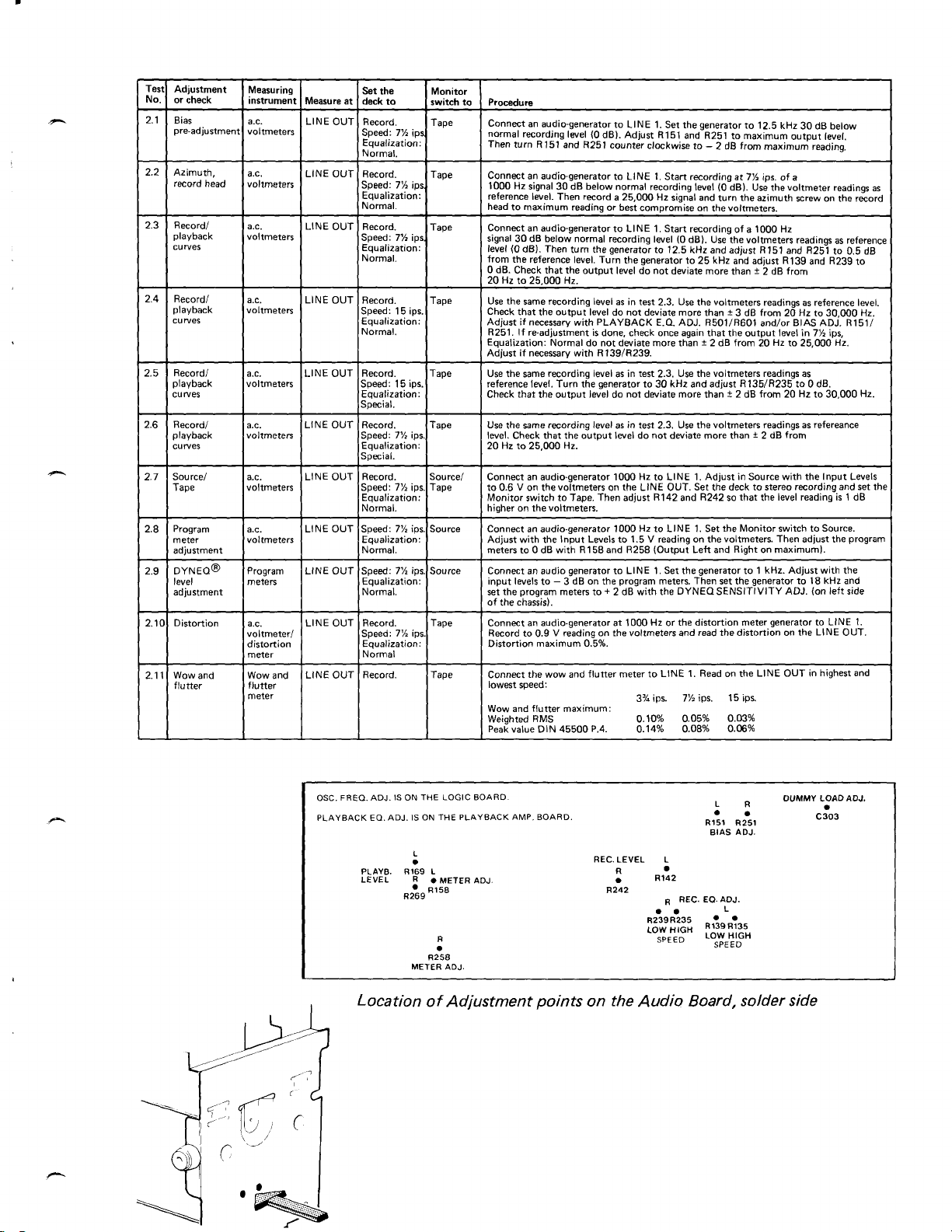
FREO. ADJ.
OSC.
PLAYBACK EO.
PLAYB. R169 L
LEVEL
Location
IS
THE LOGIC 8OARO.
ON
ADJ. IS ON
THE PLAYBACK
;
B
.METERADJ
I
qrqn
--
R269
R
a
R258
METER AOJ,
of Adjustment
AMP.
BOARD.
points
REC. LEVEL L
Ra
a
R242
the
on
Audio
Rt42
REC. EQ. ADJ.
R
aaL
i|ffl?:i
--"oi.^
LR
aa
R15r
BIAS
n,?sn?rs
Low HtGH
Board,
OUMMY
R25t
ADJ,
solder side
LOAD
a
c303
ADJ,
Page 4
*@-
6;;l
LJ
-'
mr*rff r-imir-tEffiE
I
|
FE
LJ
p;l
L.J
L-J
ti*
l*
u
t--------ri"
-fi*
F-.E F"i
u
-
L"l
-)
F
l"'
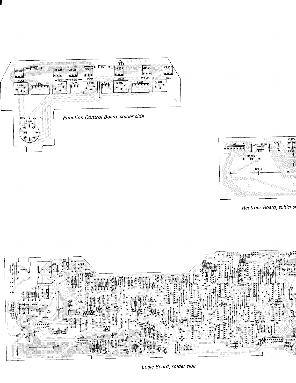
Function
Control
Board,
solder
side
A-+199--+ tr,2sf
':'"
f
l-*ry-i
1
cR 904
e-{.-.
Rectifier
sLPw
?
Board,
9S"
C
cqn rll-,
+ dF,
'
'T,
solder
fi
+
si
!r7
!
l.llL--.J
"Jl
4.1 I.
,l.ll
.l.l..",-
]I
I
R:f
-?
.I
TT
.#
"-l
Itf
Jy't
-f
1T
ta
l"
I
,:1.''.
ol
AAII
AI
ql$l
.
$1
,
'
l
I
('!L
'1.
r*?r *.,+-
ffi +*+
rr-l
,L:j,
q
.l
lr
.r
t
.l
flq
lll
ffi*fi,,,tllea,,
,-1"
li1
r.li
..
lr.rrriel
I]"t--l
ilc45G
.T
lj'tl 1,$*s'\
,H
I-
+
FFf]
#*g*j&Fl*+
,H
++rg+
ffi
q
t+
+q+1
st#f,g
F,'{lffi6,ff1
$*Pwqfl
Logic
Board,
solder
side
Page 5

I
I
I
Board,
solder
side
I
tr.+l l|'..._t
baaalaal #
H<FT
cR
.125A
a
904
7,
J 109
Rectifier
*F1-
c 903
510/v
t
I
Board,
c
ce06
.Jl-.
t
;1h'*;t,<*
solder
905 cR sol
|--.++.*.
l.l-
A
-T
ll
tt
Y
c 90r c902
+
r*1-
**t
t
-Ld-
side
-r
Logic
Board,
solder
side
l'l
iJ
t
t*
ll$l
'l
o'l:
@+ *r
...tP
,"rgurT
S't.
ttt
BBqJ
i l-L
o
,l{;l
-l:l
@l+
':
}cs
Page 6

l5
t"
t
I
l''
;
to
I
!_
I
!_
I
*[/
'_1
(ll€
:l
J
t:
lr
"
lrY
T.M l
SENSOR
iis4
r!'; |
'i
,l i
PoWER
I
-
olo
mAT 2lCVr
va rs-
al
i6rc'!!
o t-t
-Fi
I
t
REEL 5 ZE
:;i;-i
Page 7

;l
EI
2t
E8l
j,.
=r
sb=l
E2l
f?l
:::l' ?ff::lF@cwPs*
,
rL
r--{l-
.{r
I
,m.0
rm,o
I
I
TTL
!r 5N?4rr8
2 sN 74
u
U3
u{Bs -{-\
sN
u5 6
5N
ul0 sNlrL5 la
u12 5N?r C6
ta
!
'{:qN-
-0
rs0
*[';u il
u,0
e[u,0
,-0
+q n*l;rl
uri
CIRCUIIS
LS D€ I
TBP28L22N
i{
32
Ls
r
1r
L5 C8
97415279
in
","
USED:
Ta.3-L"EPFORirEratoSF
8 tNF
rO-8
L
?5613 als PRaM
-L
,r/-
{--\
r,)-
J_\
-,/
l-\
-1,
-_-/
-J>"-
L/
-Jil"--
l,/
oulmupre
l]-,
NE
s F
JEamER
Eor sEs
---lJn
.bo,g,
,!,,11"'
.,.
*.iJo;."
\-1i
I!
1
rarcr
,.II,,
rwP
. n..'
-ou
-
,,d
ti.ta
2!
i
LOGIC BOARD
r-
I
TO EOIT/CUE
:2av
r-cx
R
SW
rN
FNt
stop.
oFl
]MUrrN0
CH J R€c AMP
'rro"
OMP i
171/1-Jtl9s\15-111 05
R a38 r20R
R a(3 120R
R415
t20 Rr20 R
U3
s?2{n
VIOLEI
TCH
w ND
PrAY MoDE
N
I
.0.,1.o,
58R
l20R
ORANGE VIOLEI
L
.
-;
1,r-r116
,,
.,.
15
68R 68
220R + r20 R
220R + r2oR
ORANGE
,
"
.s
R
I
I
I
I
I
I
*."
rcroR
|
I
J
Logic Diagram
Page 8

_l
F;i
-?
I
I
o?
I'l
,,,
I
e3""se;"g
3i=:!31-o
DYNEO@
$iet
lttiliil${fft
rl G51
_l
FFj$qiiHF.aql$l
'
ffif,j$$$'#;iiii ruf$j
'eT*$HF{fiifuff
uH+bH
i'feqeH"Hl#k$
Dt NEo
to"o
I
"t
'o
I lr
r | ! llJS(
tlillt
Ilrt.
lllol'
,
tf , 1.
ril
l l: I
lt.t
,ll:1
llt'l
I ' t-,1]
.
I
t
ITN
tr.fl
|il
(J
Ls5r
BIAS
I
-J
.l
r8o5
lc95
I
I
r
f
f=\
:l
l:=t
c6r
,l
l.
,l
h
.L-1.
T
Jlr
ca62r
t
Ill
il lili
,]J
tl
I
i I
I
4,*l#l
rc-
t€
O9t3
Lo
'
Diagram
Page 9

o5&5 0605
.G@
coor&
a
I: HH.
I
#i' ll
osor
? t
IS-er r r T ,
I
rH@
lJ
'J
rl
e
lL-tN
.,,f
!
:ffHl{r
l+.'*1
*
,l
!lo^
T
oso?
"3t
I
qat
Jtat
llllp*o,.g r+lFct@
t
rrr'
,l,;lf ]'
+;il#{f
+ffiry4*
cH: 351- 39q
L
85t/95r
c35t955
c36t962
c86l/s6l
035V951
NI TAALT
561
1#'
$$e+
EO,AOARO
lt2
r5l 15
|
Tdi.',f*'
Playback
++
F
F
fi$++F
+''''T
Amplifier
T-LT
a-B_g,f
f-l
.l
l.
rl"'
ltr
l"l
t-____J
s€1.
oru
syrs.
Switch
Board, solder
+
' r "u
Board, solder
'?.
+il'
Lerr
f'---- J
l.
ltr t I
tl
".-*
["1
niGrH
t_______j
FLAYB, IiIOSS
side
$F+J+++'+l
$#
side
.l
tl
ttt.'S l.t
*rh*I
:l
lol
r$
El
IY
tl
???fl.fiAll-
I
rI
ElrFi
JI
ct6t
l
o.g
)
*u+lT,rzrll,
g
t
T
I
T
I
1""
T
I
1t
a,A$ffiffil,+
IfIEEI
TT
]l
OD
,trH.-
tt
4
I
FI
Ftl
$*-
1l
lFr
I
-T-
I
i
Fi,c
I
l++a#stitS
d
E,ldq+J
;+#ftfr*
l+ilitTt
dr*luiiAJ i*
'
'
&$i:
"rFrygTiT'
fHT;
- @
I J._l.i
T
'.fr'E
**f'
T
*
*, Tt,
u
lc
ll.
Fl, lT',
T
ffi
lil
Audio
I
tll t 1
1H'BHH
ril,
I
ob8 od "i'
Q<+
=*l i!,
t-
6
rEl
lTcruOr
l. ? It
I
F13A
$:&TF
oJ*';
pY
='
$J lI
Yr
'
TT ]BFI
r'il
'rln
Z1}
\L/
Board. solder
E 3t7
f-t
IIH
s'
I
I
tA I
I
tt ?
FII3I H
YYY
AE
H+t
(.1
C
side
Page 10

CtOl
FrcM
REC.
IO6IC XL PLAY/FASI
L L ALL OIHER
AMP
W
TO
I l*l;
I
T:"
I'
0lC6
swlTCH
''i":
I I
I
PROGR.
PART
oF LoGtc
l23kHz
ni-
6
oT-
a
METER
D
BoARD
BIAS/ERASE
I or2 |
AMP
NoEOat-
OSC.
R'$
-
lo'.'"o'o
LCA
tr-
ll.13
ln.
F}
-.1
::;.;
it-A'
-
I
I
1.t12
REC
)iili-z
It---
9E!EC
.\€2tr
-E_:
d-
{a\
l:
;"
15
t,
e
Na
I
a-
,.F
i:
--1
l!l
,:-_/::
|
t";
I
ll
L
.
-t-.-l
L"
'
Audio
Diagram
Page 11

FrcI
LOGIC HL PLAY/FASI
REC. AMP
L L ALL O'HEF XOOES
WINO/FREE
EOUAL.PLAYB. AMP
PART
OF BOARD NO.63607
BOOSTER,
FILTER
L.P
D
BoARD
NO.63685
,/ERASEi5C--_loo
;;-----l
'"o,o
)LtL z
i
L5'J.--JL____J5
-tii.:rTI'i
1
|
I
DUMMY
LOAD
li
TrJ'
"T
4
D
-l_
t;
@
@
A
z.
o
(D
I
(J
=
-
a
t:
I
3f,
I
J
t-'
c?35
!r3ol-r?
R?70
R2?l
L.CH
T
t00i
fiABG;
33oR
32R
32k
2tz
NICI
NTCI
roii
2t5
l2
0r
56k
2 ?OR
2-M
rk5
220R
a2t
rwg
-__-,
: :!.'
L\
'
tt
_)_
PARI OF BOARD NO.
FRoM Lo6rc:
i106
:
LrrtPr^\soF
rN
H L
alr
orqtR
MoDEs.
FROMLOGIC
AL PLAY/fW /FREf
53607
Page 12

Tandberg
The
European
Tandberg
Fetveien
N-2007
1, P.O.
Kjeller, Norway
Alternative
A/S
Box 53
a-E
^O-
o
c
o
-
E
o
o
-o
o
E
z
;
o
c
'I
@
r
s
r
z
o
r
r
A
 Loading...