

Page 1

User Manual
Software version F5
D13358.07
June 2006
This document is not to be reproduced in whole or in part without permission in writing from:
Page 2
TANDBERG Maestro MXP
Trademarks and Copyright
All rights reserved. This document contains information that is proprietary to TANDBERG. No part
of this publication may be reproduced, stored in a retrieval system, or transmitted, in any form, or
by any means, electronically, mechanically, by photocopying, or otherwise, without the prior
written permission of TANDBERG. Nationally and internationally recognized trademarks and
trade names are the property of their respective holders and are hereby acknowledged.
Third Party Software
Amended / Expanded Copyright notices for third-party software on the TANDBERG MXP systems
are listed below:
Full copies of the licenses and warranty statements are located on the product CD in the license
files directory.
The non-commercial third party code is distributed in binary form under the terms of non-copyleft
style open source licenses such as BSD, Artistic or MIT/X Consortium.
The product also has some binary code distributed under the terms of the GNU public license
with an exemption which allows static links to non-copyleft commercial code.
In accordance with section (3) of the GNU General Public License, copies of such code will be
provided upon request by contacting TANDBERG. Please contact us by using the Online Support
section at
www.tandberg.net or the “contact us” section of this manual. Please provide USD
10.00 for media and shipping.
Agfa
Contains iType™ from Monotype Imaging Corporation.
CMU-SNMP
Copyright 1988, 1989, 1991, 1992 by Carnegie Mellon University All Rights Reserved
CMU-SNMP is distributed under the terms of the CMU SNMP license, which is an open source license similar to a BSD or
X Consortium License.
Dropbear - an SSH2 server
Copyright (c) 2002,2003 Matt Johnston All rights reserved.
The Dropbear SSH2 server is distributed under the terms of the Dropbear License, which is a MIT/X Consortium style
open source license.
ii
Page 3

User Manual
eCos
eCos, the Embedded Configurable Operating System.
Copyright (C) 1998, 1999, 2000, 2001, 2002, 2003 Red Hat, Inc.
Copyright (C) 2002, 2003 John Dallaway
Copyright (C) 2002, 2003 Nick Garnett
Copyright (C) 2002, 2003 Jonathan Larmour Copyright (C) 2002, 2003 Andrew Lunn Copyright (C) 2002, 2003 Gary
Thomas Copyright (C) 2002, 2003 Bart Veer
Copyright (c) 1982, 1986, 1991, 1993 The Regents of the University of California. All rights reserved.
(c) UNIX System Laboratories, Inc.
All or some portions of this file are derived from material licensed to the University of California by American Telephone
and Telegraph Co. or Unix System Laboratories, Inc. and are reproduced herein with the permission of UNIX System
Laboratories, Inc.
Copyright (C) 1995, 1996, 1997, and 1998 WIDE Project. * All rights reserved.
Copyright (c) 2000 Brian Somers <brian@Awfulhak.org>
Copyright (c) 1998 The NetBSD Foundation, Inc. * All rights reserved.
Copyright (c) 1997 Niklas Hallqvist. All rights reserved.
Copyright (c) 1988 Stephen Deering.
Copyright (c) 1992, 1993 The Regents of the University of California. All rights reserved.
This code is derived from software contributed to Berkeley by Stephen Deering of Stanford University.
Portions of eCos code are distributed under several BSD style licenses. Other portions of eCos code are distributed under
the terms of the GNU General Public License with a non-copyleft exception which allows static links to non-copyleft
programs.
ExPat XML Parser:
Copyright (c) 1998, 1999, 2000 Thai Open Source Software Center Ltd and Clark Cooper
Copyright (c) 2001, 2002, 2003, 2004, 2005, 2006 Expat maintainers.
The ExPat XML parser is distributed under the terms of the ExPat License which is a MIT/X Consortium style open
source license
ICU
ICU License - ICU 1.8.1 Copyright (c) 1995-2003 International Business Machines Corporation and others All rights
reserved.
ICU is distributed under the terms of the ICU license, which is a MIT/X Consortium style license.
OpenSSL
Copyright (c) 1998-2004 The OpenSSL Project. All rights reserved.
This product includes software developed by the OpenSSL Project for use in the OpenSSL Toolkit
(http://www.openssl.org/)"
Copyright (C) 1995-1998 Eric Young (eay@cryptsoft.com) * All rights reserved.
OpenSSL is distributed under the terms of the OpenSSL and SSLeay licenses, which are both BSD style open source
licenses.
iii
Page 4

TANDBERG Maestro MXP
snprintf
Copyright 1999, Mark Martinec. mark.martinec@ijs.si All rights reserved
Snprintf is distributed under the terms of the snprintf license, which is a Frontier Artistic style open source license.
A standard copy of snprintf can be located at the author’s web site: http://www.ijs.si/software/snprintf/
xSupplicant (wpa_supplicant) 802.1x
Copyright (c) 2002-2005, Jouni Malinen jkmaline@cc.hut.fi
xSupplicant is distributed under the terms of the xSupplicant license, which is a BSD style open source license.
Disclaimer
The information in this document is furnished for informational purposes only, is subject to
change without prior notice, and should not be construed as a commitment by TANDBERG. The
information in this document is believed to be accurate and reliable; however TANDBERG
assumes no responsibility or liability for any errors or inaccuracies that may appear in this
document, nor for any infringements of patents or other rights of third parties resulting from its
use. No license is granted under any patents or patent rights of TANDBERG.
This document was written by the Research and Development Department of TANDBERG,
Norway. We are committed to maintain a high level of quality in all our documentation. Towards
this effort, we welcome you to
Contact us with comments and suggestions regarding the content
and structure of this document.
Patent information
TANDBERG technology described in this manual is protected by one or more of the following
U.S. Patent No. 5,584,077 - 5,838,664 - 5,600,646 - 7,010,119 - 7,034,860 and other patents are
pending in the United States and/or other countries.
COPYRIGHT © 2005–2006, TANDBERG
iv
Page 5
Environmental Issues
User Manual
Thank you for buying a product which contributes to a reduction in pollution, and thereby helps
save the environment. Our products reduce the need for travel and transport and thereby reduce
pollution. Our products have either none or few consumable parts (chemicals, toner, gas, paper).
Our products are low energy consuming products.
TANDBERG’s Environmental Policy
Environmental stewardship is important to TANDBERG’s culture. As a global company with
strong corporate values, TANDBERG is committed to being an environmental leader and
embracing technologies that help companies, individuals and communities creatively address
environmental challenges.
TANDBERG’s environmental objectives are to:
Develop products that reduce energy consumption, CO
Provide products and services that improve quality of life for our customers
Produce products that can be recycled or disposed of safely at the end of product life
Comply with all relevant environmental legislation.
European Environmental Directives
As a manufacturer of electrical and electronic equipment TANDBERG is responsible for
compliance with the requirements in the European Directives 2002/96/EC (WEEE) and
2002/95/EC (RoHS).
The primary aim of the WEEE Directive and RoHS Directive is to reduce the impact of disposal of
electrical and electronic equipment at end-of-life. The WEEE Directive aims to reduce the amount
of WEEE sent for disposal to landfill or incineration by requiring producers to arrange for
collection and recycling. The RoHS Directive bans the use of certain heavy metals and
brominates flame retardants to reduce the environmental impact of WEEE which is land filled or
incinerated.
TANDBERG has implemented necessary process changes to comply with the European RoHS
Directive (2002/95/EC) and the European WEEE Directive (2002/96/EC).
Waste Handling
In order to avoid the dissemination of hazardous substances in our
environment and to diminish the pressure on natural resources, we
encourage you to use the appropriate take-back systems in your area.
Those systems will reuse or recycle most of the materials of your end
of life equipment in a sound way.
TANDBERG products put on the market after August 2005 are
marked with a crossed-out wheelie bin symbol that invites you to use
those take-back systems.
Please contact your local supplier, the regional waste administration or
http://www.tandberg.net/recycling if you need more information on the collection and recycling
system in your area.
emissions, and traffic congestion
2
v
Page 6

TANDBERG Maestro MXP
Information for Recyclers
As part of compliance with the European WEEE Directive, TANDBERG provides recycling
information on request for all types of new equipment put on the market in Europe after August
13th 2005.
Please contact TANDBERG at
recycling@tandberg.net and provide the following details for the
product for which you would like to receive recycling information:
Model number of TANDBERG product
Your company’s name
Contact name
Address
Telephone number
E-mail address
Digital User Guides
TANDBERG is pleased to announce that we have replaced the printed versio ns of our User
Guides with a digital CD version. Instead of a range of different user manuals, there is now one
CD – which can be used with all TANDBERG products – in a variety of languages. The
environmental benefits of this are significant. The CDs are recyclable and the savings on paper
are huge. A simple web-based search feature helps you directly access the information you need.
In addition, the TANDBERG video systems now have an intuitive on-screen help function, which
provides a range of useful features and tips. The contents of the CD can still be printed locally,
whenever needed.
vi
Page 7

Operator Safety Summary
User Manual
Operator Safety Summary
For your protection please read these safety instructions completely before you connect the
equipment to the power source. Carefully observe all warnings, precautions and instructions both
on the apparatus and in these operating instructions.
Keep this manual for future reference.
Water and Moisture
Do not operate the apparatus under or near water - for example near a bathtub, kitchen
sink, or laundry tub, in a wet basement, near a swimming pool or in other areas with high
humidity.
Never install jacks for communication cables in wet locations unless the jack is
specifically designed for wet locations.
Do not touch the product with wet hands.
Cleaning
Unplug the apparatus from communication lines, mains power-outlet or any power source
before cleaning or polishing. Do not use liquid cleaners or aerosol cleaners. Use a lintfree cloth lightly moistened with water for cleaning the exterior of the apparatus.
Unplug the apparatus from communication lines before cleaning or polishing. Do not use
liquid cleaners or aerosol cleaners. Use a lint-free cloth lightly moistened with water for
cleaning the exterior of the apparatus.
Ventilation
Do not block any of the ventilation openings of the apparatus. Never cover the slots and
openings with a cloth or other material. Never install the apparatus near heat sou r ces
such as radiators, heat registers, stoves, or other apparatus (including amplifiers) that
produce heat.
Do not place the product in direct sunlight or close to a surface directly heated by the
sun.
Lightning
Never use this apparatus, or connect/disconnect communication cables or po wer cables
during lightning storms.
Dust
Do not operate the apparatus in areas with high concentration of dust
Vibration
Do not operate the apparatus in areas with vibration or place it on an unstable surface.
Power connection and Hazardous voltage
The product may have hazardous voltage inside. Never attempt to open this product, or
any peripherals connected to the product, where this action requires a tool.
This product should always be powered from an earthed power outlet.
Never connect attached power supply cord to other products.
vii
Page 8

TANDBERG Maestro MXP
In case any parts of the product has visual damage never attempt to connect mains
power, or any other power source, before consulting service personnel
The plug connecting the power cord to the product/power supply se rves as the main
disconnect device for this equipment. The power cord must always be easily accessible.
Route the power cord so as to avoid it being walked on or pinched by items placed upon
or against it. Pay particular attention to the plugs, receptacles and the point where the
cord exits from the apparatus.
Do not tug the power cord
If the provided plug does not fit into your outlet, consult an electrician.
Never install cables, or any peripherals, without first unplugging the device from it's power
source.
*Always use the power supply (AC-DC adapter) provided with this product.
*Replace only with power supply (AC-DC adapter) specified by TANDBERG.
*Never connect attached power supply (AC-DC adapter) to other products.
Servicing
Do not attempt to service the apparatus yourself as opening or removing covers may
expose you to dangerous voltages or other hazards, and will void the warranty. Refer all
servicing to qualified service personnel.
Unplug the apparatus from it's power source and refer servicing to qualified personnel
under the following conditions:
- If the power cord or plug is damaged or frayed.
- If liquid has been spilled into the apparatus.
- If objects have fallen into the apparatus.
- If the apparatus has been exposed to rain or moisture
- If the apparatus has been subjected to excessive shock by being dropped.
- If the cabinet has been damaged.
- If the apparatus seems to be overheated.
- If the apparatus emits smoke or abnormal odor.
- If the apparatus fails to operate in accordance with the operating instructions
Accessories
Use only accessories specified by the manufacturer, or sold with the apparatus.
Communication lines
Never touch uninstalled communication wires or terminals unle ss the telephone line has
been disconnected at the network interface.
Do not use communication equipment to report a gas leak in the vicinity of the leak.
To reduce the risk of fire, use only No. 26 AWG or larger telecommunication line cord
(ISDN cables).
* Applies to the following products: T150 MXP, T550 MXP, T770 MXP, T880 MXP, T990 MXP, T1500 MXP, T1000 MXP,
T2000 MXP, T3000 MXP Profile, Tandberg Codec 3000 MXP, Tandberg Tactical MXP, Edge 75/85/95 MXP.
viii
Page 9

Contact us
User Manual
If you have any questions, comments or suggestions, please see the
www.tandberg.net.
It is also possible to send a fax or mail to the attention of:
Product and Sales Support
TANDBERG
P.O. Box 92
1325 Lysaker
Norway
Tel: +47 67 125 125
Fax: +47 67 125 234
Online Support section at
ix
Page 10

TANDBERG Maestro MXP
Table of Contents
1 Introduction............................................................................................................................. 14
1.1 At a Glance .......................................................................................................................... 18
1.2 Menu Structure .................................................................................................................... 22
2 Installation .............................................................................................................................. 24
2.1 Unpacking and Mounting.....................................................................................................25
2.2 Connecting Cables............................................................................................................... 27
2.3 Monitor Configuration........................................................................................................... 29
2.4 System Configuration........................................................................................................... 30
3 General Use ........................................................................................................................... 33
3.1 The Welcome Screen .......................................................................................................... 34
3.2 Using the Remote Control.................................................................................................... 35
3.2.1 Navigation................................................................................................................ 39
3.2.2 Selfview.................................................................................................................... 40
3.2.3 Picture Layout.......................................................................................................... 42
3.2.4 Mic Off...................................................................................................................... 43
3.2.5 Volume + and -......................................................................................................... 44
3.2.6 Number and Letter keys........................................................................................... 45
3.2.7 Touch Tones............................................................................................................ 46
3.2.8 Presets and Extension Numbers............................................................................. 47
3.3 On-screen Indicators............................................................................................................ 48
3.4 Using the Menu.................................................................................................................... 50
3.5 Make a Call.......................................................................................................................... 52
3.5.1 Place a Call.............................................................................................................. 53
3.5.2 Add Call ................................................................................................................... 55
3.5.3 Call Settings............................................................................................................. 56
3.5.4 SIP Services ............................................................................................................ 57
3.5.5 Streaming................................................................................................................. 58
3.5.6 Dialing In From Outside the Enterprise.................................................................... 60
3.6 Answer an incoming call...................................................................................................... 61
3.7 End Call................................................................................................................................ 62
3.8 Standby................................................................................................................................ 63
3.8.1 Delay Standby for 1 hour......................................................................................... 64
3.8.2 Delay Standby for 3 hours....................................................................................... 65
3.8.3 Do Not Disturb ......................................................................................................... 66
3.9 Phone Book ......................................................................................................................... 67
3.9.1 Call Log.................................................................................................................... 69
3.9.2 My Contacts............................................................................................................. 70
3.9.3 Global Contacts ....................................................................................................... 77
3.10 Camera Control.................................................................................................................. 81
3.10.1 Move Camera .......................................................................................................... 82
3.10.2 Far End Control........................................................................................................ 83
3.10.3 Camera Presets....................................................................................................... 84
3.10.4 TANDBERG Tracker................................................................................................ 85
3.10.5 Picture Control......................................................................................................... 86
3.10.6 Camera Tracking ..................................................................................................... 88
3.11 Presentation....................................................................................................................... 89
3.11.1 Presentation Key...................................................................................................... 90
3.11.2 Presentation Menu................................................................................................... 91
3.11.3 PC Presenter (DVI/VGA Input)................................................................................ 92
3.11.4 PC Soft Presenter and VNC.................................................................................... 93
x
Page 11

User Manual
3.11.5 Dual Stream (DuoVideoTF/H.239)............................................................................ 94
3.11.6 Take New Snapshot................................................................................................. 95
3.11.7 Display Snapshot..................................................................................................... 96
3.12 Services ............................................................................................................................. 97
3.12.1 Request Floor and Release Floor.......................................................................... 100
3.12.2 Conference Layout................................................................................................. 101
3.12.3 Terminal Names..................................................................................................... 102
3.12.4 Chair Control.......................................................................................................... 103
3.12.5 Assign Floor and Release Floor from Participant.................................................. 104
3.12.6 View Site and End View......................................................................................... 105
3.12.7 Disconnect Participant........................................................................................... 106
3.12.8 Terminate Meeting................................................................................................. 107
3.12.9 More about MultiSite (embedded MCU)................................................................ 108
3.12.10 Text Chat........................................................................................................... 110
4 Control Panel........................................................................................................................ 111
4.1 User Guide......................................................................................................................... 112
4.2 Diagnostics ........................................................................................................................ 113
4.2.1 System Information................................................................................................ 114
4.2.2 Channel Status ...................................................................................................... 115
4.2.3 Call Status.............................................................................................................. 117
4.2.4 System Selftest...................................................................................................... 118
4.2.5 View Settings......................................................................................................... 119
4.2.6 IP Address Conflict Check..................................................................................... 124
4.2.7 Warnings................................................................................................................ 125
4.3 Audio Demo ....................................................................................................................... 127
4.4 Restart................................................................................................................................ 128
5 System Settings ................................................................................................................... 129
5.1 General Settings................................................................................................................ 130
5.1.1 Language............................................................................................................... 131
5.1.2 System Name ........................................................................................................ 132
5.1.3 International Name................................................................................................. 133
5.1.4 Auto Answer........................................................................................................... 134
5.1.5 Phone Book Settings ............................................................................................. 135
5.1.6 External Services Settings..................................................................................... 136
5.1.7 Permissions ........................................................................................................... 137
5.1.8 Screen Settings...................................................................................................... 139
5.1.9 Software Options ................................................................................................... 145
5.1.10 Date and Time Settings ......................................................................................... 146
5.2 Menu Settings.................................................................................................................... 147
5.2.1 Input Editor Language............................................................................................ 148
5.2.2 Menu Timeout in Call............................................................................................. 149
5.2.3 Menu on TV ........................................................................................................... 150
5.2.4 Menu on PC........................................................................................................... 151
5.2.5 Balloon Help........................................................................................................... 152
5.2.6 Number Key Mode................................................................................................. 153
5.2.7 Administrator Password......................................................................................... 156
5.2.8 Kiosk Mode Settings.............................................................................................. 157
5.2.9 Startup ................................................................................................................... 160
5.2.10 Icons....................................................................................................................... 162
5.3 Presentation Settings......................................................................................................... 163
5.3.1 Presentation Start.................................................................................................. 164
5.3.2 H.239 ..................................................................................................................... 165
5.3.3 Startup Video Source............................................................................................. 166
5.3.4 Presentation Source .............................................................................................. 167
5.3.5 Snapshot Source ................................................................................................... 168
5.3.6 Auto-Display Snapshot.......................................................................................... 169
xi
Page 12

TANDBERG Maestro MXP
5.3.7 PIP Placing ............................................................................................................ 170
5.3.8 Presentation Rate.................................................................................................. 171
5.3.9 VNC Settings ......................................................................................................... 172
5.4 Call Quality......................................................................................................................... 173
5.4.1 Video Algorithm...................................................................................................... 174
5.4.2 Audio Algorithm...................................................................................................... 175
5.4.3 AAC-LD 128kbps (stereo audio)............................................................................ 176
5.4.4 Natural Video......................................................................................................... 177
5.4.5 Max Upstream Rate (kbps).................................................................................... 178
5.4.6 Video Quality.......................................................................................................... 179
5.4.7 Call Settings........................................................................................................... 182
5.5 Audio.................................................................................................................................. 185
5.5.1 Inputs ..................................................................................................................... 186
5.5.2 Outputs .................................................................................................................. 190
5.5.3 Echo Control.......................................................................................................... 192
5.5.4 Stereo Settings ...................................................................................................... 193
5.5.5 Audio Leveling (AGC)............................................................................................ 195
5.5.6 Alert Tones and Volume ........................................................................................ 196
5.5.7 Graphical View....................................................................................................... 197
5.6 Video.................................................................................................................................. 198
5.6.1 Camera Tracking Mode ......................................................................................... 199
5.6.2 MCU Status Line.................................................................................................... 200
5.6.3 Floor to Full Screen................................................................................................ 201
5.6.4 Web Snapshots...................................................................................................... 202
5.6.5 MultiSite Picture Mode........................................................................................... 203
5.6.6 Video Name........................................................................................................... 205
5.7 Security.............................................................................................................................. 206
5.7.1 Encryption.............................................................................................................. 207
5.7.2 Encryption Mode.................................................................................................... 208
5.7.3 Passwords ............................................................................................................. 209
5.7.4 Camera Standby Mode.......................................................................................... 210
5.8 Network.............................................................................................................................. 211
5.8.1 ISDN/External/Leased E1/T1................................................................................. 212
5.8.2 LAN Settings.......................................................................................................... 222
5.8.3 Network Profiles..................................................................................................... 239
5.8.4 Data Port................................................................................................................ 240
5.8.5 Restore Default Settings........................................................................................ 241
6 Peripheral Equipment........................................................................................................... 242
6.1 Interfaces ........................................................................................................................... 243
6.1.1 Video...................................................................................................................... 243
6.1.2 Audio...................................................................................................................... 248
6.1.3 Network.................................................................................................................. 250
6.1.4 Data port................................................................................................................ 255
6.2 Document Camera............................................................................................................. 256
6.3 DVD / VCR......................................................................................................................... 257
6.4 Additional Cameras............................................................................................................ 258
6.5 Additional Microphones...................................................................................................... 259
6.6 The TANDBERG DNAM and Speakers............................................................................. 261
6.7 Stereo Speaker Kit............................................................................................................. 265
6.8 Telephone Add-On............................................................................................................. 267
6.9 Dual Monitor....................................................................................................................... 268
6.10 XGA Monitors and Projectors .......................................................................................... 269
6.11 VESA Display Power Management................................................................................. 270
6.12 Digital Monitor Power Management................................................................................. 271
6.13 Extended Display Identification Data (EDID)................................................................... 272
7 Appendices........................................................................................................................... 274
xii
Page 13

User Manual
Appendix 1: Technical Specifications ...................................................................................... 275
Appendix 2: Bandwidth Information for TANDBERG Endpoints.............................................. 278
Appendix 3: Environmental Considerations............................................................................. 280
Appendix 4: Guidelines for Settings up Rooms for Video Meetings........................................ 281
Appendix 5: Security................................................................................................................ 282
Appendix 6: Using the File System.......................................................................................... 285
Appendix 7: Web Interface....................................................................................................... 286
Appendix 8: Connecting the System to PRI/T1 ....................................................................... 287
Appendix 9: Connecting the System to Switched 56 Network................................................. 288
Appendix 10: Connecting the System to ISDN using NT1 Network Adapters......................... 289
Appendix 11: TANDBERG Cameras....................................................................................... 291
Appendix 12: Remote Control (TRC3 / TRC4) ........................................................................ 298
Appendix 13: Cisco Call Manager Registration....................................................................... 301
Appendix 14: Diagnostic Tools for IP....................................................................................... 302
Appendix 15: System Upgrade................................................................................................ 304
Appendix 16: Declaration of Conformity.................................................................................. 309
Appendix 17: Dimensions........................................................................................................ 310
Appendix 18: Protocols Supported.......................................................................................... 313
Appendix 19: Cable Specifications.......................................................................................... 315
8 Glossary ............................................................................................................................... 323
9 Index..................................................................................................................................... 332
xiii
Page 14

1 Introduction
The TANDBERG Maestro MXP provides high-end performance features, high resolution quality
video and precision audio. This creates a collaborative meeting environment for medium to largesized meeting rooms.
TANDBERG Precision HD Camera
To provide customers with optimal video processing and picture perfect quality, TANDBERG has
created the TANDBERG Precision HD Camera custom-designed for videoconferencing. Whether
using high definition for detail or a 3G device for mobility, the optimal definition ensures the
highest picture quality possible, letting video users enjoy the best resolution at the bandwidth
available and for their situation.
NEW Precision High Definition Camera for selected TANDBERG MXP systems
TANDBERG Precision HD Camera:
• High Resolution, 1280x720p@30fps
• High quality colors and dynamic range
• Low noise in low light conditions
• 70° wide angle lens with 7x zoom
• High quality image sharpness
• Fully Automatic
Users can dial in from a video system outside the enterprise without being registered to a
gatekeeper
The feature enhancement enables dialing through a TANDBERG Gatekeeper without being
registered to it. This makes it easy to call in from a video system outside the enterprise.
To be able to make such a call, this feature must be enabled in your gatekeeper or border
controller, and the called endpoint must be registered with the enterprise gatekeeper or border
controller.
NEW Users can dial in from a video system outside the enterprise without being
registered to a gatekeeper, i.e. dialing from/using a global IP address.
SIP Services
SIP Services enables the user to use the features Add Call and Transfer. To get the SIP Services
available you select SIP as your Net when you make a call. You must have a SIP registrar/VoIP
solution that supports this.
NEW Enhanced SIP services to enable rich services like call transfer and suspend.
Enables integration into Video and Voice over IP (V
Microsoft, Nortel and Avaya.
2
oIP) solutions from
Page 15

Installation
Controllable Bandwidth
When setting up a call with H.323 the bandwidth can be controlled by the user by setting the
Presentation Rate.
The Presentation Rate is expressed in percent of the Call Rate and shall reflect the H.323
Presentation Rate settings of the sender.
Graphical View of the Audio Streams
The graphical view gives a visual presentation of the active audio streams for the input sources
and the output sources.
In addition the user can play a Test Tone for each audio input and output source.
Presets and Extension Numbers
While in a call, the user presses a number key on remote control to:
• add another call
• dial extension numbers
• use camera presets
The system can be configured to act automatic or to give the user a choice of what to do every
time the user presses a number key on the remote control, when in a call.
Audio Quality
High-performance audio provides a richer, more complete visual communication experience. The
MPEG4 AAC-LD standard is used to provide true standards-based CD-quality, stereo audio.
TM
The Digital Natural Audio Module
(DNAM), specifically designed for video meetings, provides
higher fidelity sound for more natural sounding spoken-word. The DNAM features 250W of
power.
Users can record and send stereo audio from stereo presentation and playback sources using
PCs, DVDs and VCRs using the proper cables.
Disturbance from GSM mobile phones and Blackberry devices is eliminated by a noise filter.
Video Quality
Features which ensure high quality video include:
Precision HD Camera, 1280x720 progressive scan @ 30fps
Support for H.264 in MultiSite, Dual Video and encryption.
SXGA input and 2 x XGA, up to WXGA or 720p output through DVI-I (analog or digital).
H.264 video compression up to 2Mbps.
Support for native 16:9 and Wide XGA monitors (1280x768)
NEW High Definition (HD) Support on TANDBERG MXP systems with a DVI input and
output
Network
The system supports video meetings via both IP and ISDN networks. The bandwidth capabilities
are:
up to 4Mbps* on IP
15
Page 16

TANDBERG Maestro MXP
up to 2Mbps* on ISDN
up to 6Mbps* IP in MultiSite.
H320, H323 and SIP support, for both point-to-point and MultiSite*.
TF
If channels are dropped during a video meeting session, downspeeding
automatically maintains
connections without interruption.
Security
TF
Secure Conference
provides embedded encryption for both Point-to-Point and MultiSite call and
ensures both privacy and security.
The system is delivered with integrated Expressway™ firewall traversal technology. When used
together with a TANDBERG Border Controller it enables:
Secure and seamless traversal of ANY firewall.
No missing features when traversing the firewall – works with H.264, MPEG4 audio,
encryption.
H.460.18 and H.460.19 ITU Standardized firewall traversal, support.
Outside systems, such as home office s, to be part of the enterprise dial plan.
Dialing to systems by numbers or URI, e.g.
user@company.com.
NEW Highest level of embedded encryption as well as IEEE 802.1x and H.235
authentication for security
MultiSite*
The optional embedded MultiSite
TF
functionality can connect up to 6 video sites and 5 audio sites.
Embedded MultiSite supports screen layouts such as VoiceSwitched, AutoSplit, 4 Split and 5+1
Split. The optional embedded MultiSite functionality supports any combination of ISDN and IP
participants in a conference (up to the total).
Superior quality and reliability in MultiSite calls is ensured by the systems support for:
DuoVideo/H.239 to provide for presenting full PC resolution information
H235, 802.1x and AES and DES encryption to provide security
H.264 video algorithm to provide the best video at all bandwidths
TF
Rate matching
Transcoding
to support different call rates for all sites in a MultiSite
TF
to support different protocols for all sites in a MultiSite.
The TANDBERG video communication system can also be used as an audio telephone bridge
(assuming ISDN connection(s)).
Presentations
The Natural Presenter Package* (NPP) makes it possible to include PC presentations in
videoconferences and comprises:
TF
Digital Clarity
Duo Video
which transmits exceptionally high-quality, native resolution video.
TF
/H.239 which allows participants at the far end to simultaneously watch a
presenter on one screen and a live PC presentation in native resolution on a second
monitor (up to SXGA on compatible monitors).
TF
PC Presenter
which allows a PC connection via standard DVI/VGA cable supporting up
to SXGA resolution.
TF
PC SoftPresenter
which shows PC images via a LAN connection supporting XGA
resolution.
Auto Layout to automatically choose the best layout for the call.
16
Page 17

Installation
PC Zoom which allows the native resolution PC image to be zoomed in/out with the
remote control to get SXGA resolution.
Users can display video and presentations in the best layout based on the situation. Supported
screen layouts are:
Picture in Picture (PiP)
Picture outside Picture (PoP)
Side by Side
User interfaces
A web-interface to the codec provides:
System management, diagnostics and software uploads.
Text chat/closed captioning.
Unicast Streaming – which allows broadcasting of audio/video via an IP network to a
single compatible client (RealMedia™ or Apple Quicktime™) or streaming server.
The On-Screen Menu:
Provides an easy interface for first-time users with symbols and descriptions.
Builds upon the familiar current interface.
Enhanced language support with Asian and non-Latin character text input in the menu for
local language system names
Simplified on-screen menu, Kiosk Mode, for special purposes
The remote control has a simplified look and feel, an auto system wake-up when picked up, and
large, easy-to-read keys.
Interoperability
The TANDBERG Maestro MXP is worldwide compatible with other ITU standards-based video
communication systems from many other vendors worldwide.
* - optional feature. To check which options are installed, select Control Panel - Diagnostics - System Information in the
menu.
TF
- TANDBERG First
17
Page 18
TANDBERG Maestro MXP
1.1 At a Glance
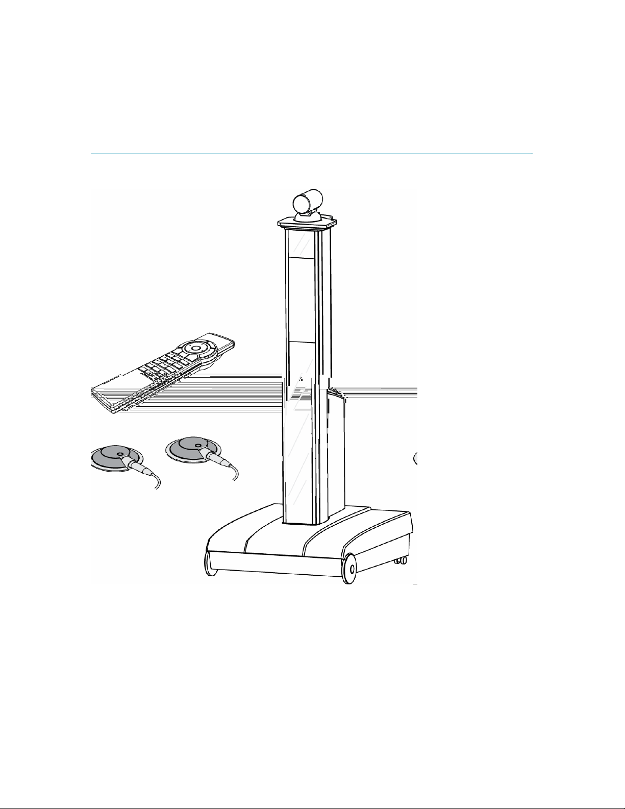
TANDBERG Maestro MXP
TANDBERG Cameras
TANDBERG Maestro MXP is delivered with TANDBERG Precision HD Camera and TANDBERG
MXP Codec, which give a high definition video quality and are optimized for video meetings.
TANDBERG Maestro MXP is also designed to work with the WAVE II (Wide Angle View)
Camera. The WAVE II Camera delivers the widest angle of view in the industry.
TANDBERG Precision HD Camera
The Precision HD Camera is mounted on top of the product. The camera is a high resolution
quality color camera with a fast pan/tilt/zoom/focus action. It is controlled by the system’s remote
18
Page 19

Installation
control which operates pan, tilt, focus, zoom and backlight compensation. Up to fifteen camera
positions can be pre-stored using Camera Presets.
TANDBERG WAVE II Camera
The TANDBERG Wave II Camera includes a high quality color camera with a fast
pan/tilt/zoom/focus action. The main camera is controlled by the system’s infrared remote control
and operates pan/tilt, focus and zoom. Up to fifteen camera positions can be pre-stored using
Camera Presets.
A locking mechanism fixates the camera on top of the product. To release the locking mechanism
and remove the camera push the grey button on the rear end of the camera stand
Internal LCD Display
The system has a built-in 5inch LCD designed to optimize system configuration and give the user
access to menus and test video signals without attaching or powering an external display device.
The LCD gives full control of all system settings and status. Below the LCD there are three
system indicators, one red light indicating that the system is powered, one yellow light indicate
that a call is active, and one green light indicate that the table microphones are muted.
External display
The TANDBERG Maestro is designed to give unlimited flexibility on the choice of display
technologies and solutions to display video, and is an ideal solution for large meeting rooms
which already are equipped with e.g. front projector and screen. For transferring video signal to
one or more external display devices the Codec has the following video outputs:
- DVI-I analog or digital interface
- XGA
- MiniDin, S-video
19
Page 20

TANDBERG Maestro MXP
- RCA / Phono, Composite video
It is recommended to use a DVI-I or XGA connection between the TANDBERG Maestro and the
external display device to obtain best quality of video and PC presentation. Read user manual on
the display device for configuration of settings at external display to meet setting at the Codec.
Codec
The codec is the heart of the system. Its main task is the compression of outgoing video, audio
and data, the transmission of this information to the far end and the decompression of the
incoming information - the name codec comes from a combination of the two wo rds compression
and decompression.
The system is easily movable with four wheels and one handle. The codec is located inside the
pedestal and behind the codec cover, which is easy removable. The pedestal stands on a solid
base with an access hatch on the rear. On the inside of the hatch there are pockets for storing
remote control and microphones. Pull the hatch to open. Inside the base there is room for
additional equipment, e.g. a VCR/DVD, and for storage of cables. The Digital Natural Audio
Module is built into the pedestal.
Remote Control
The remote control is used to control all functions of the system. If the screen saver is activated
(black monitor), touching the remote control will automatically wake up the system. The remote
control uses 4 AAA batteries. . Please follow the guidelines on the packing material for handling
and disposal instructions for the batteries.
The reach of the remote control signal is 20 meters (65 ft). The remote control IR receiver is
located on the camera. For users working in an open environment with multiple systems
deployed, this can cause other systems to respond to your remote control. Use the little, white
switch placed under the batteries to change the reach of the signal from 20 meters (65 ft) to 2
meters (6.5 ft). This will prevent you from unintentionally controlling another video system, when
you control your own system.
If the screen saver is activated (black or blank monitor), pick up the remote control and touch the
sides. This will automatically wake up the system.
Microphone
The high quality table microphone is designed to be placed on a table during a videoconference.
Up to three microphones can be connected. The ideal location for the microphone is on a flat
surface at least 2m (6.5 ft) from the front of the system. The microphone cable should always
point towards the system. The system will automatically equalize sound levels. Loud and soft
voices are picked up and transmitted to the far end at approximately the same level.
20
Page 21

Installation
Digital Natural Audio Module
The Digital Natural Audio Module (DNAM) is designed to enhance the audio quality during a
videoconference. The DNAM provides natural sounding audio, as if the person or another sound
source in the conference is present in the same room as you.
The DNAM is a frequency-compensated sound system optimized for voice and other sounds that
appears in modern video systems. It is designed and dedicated specifically for video meeting
requirements. The use of the highest quality speaker elements as well as proper amplifier- and
software techniques minimizes signal distortion.
The system will automatically detect the DNAM and optimize the audio output. Once detected the
audio output will be in digital format (S/PDIF). The DNAM supports both analog and digital input.
The DNAM amplifier and speaker cabinet are integrated directly into the Maestro pedestal.
TANDBERG Tracker
The tracker is a small infrared remote control device made
to steer the camera to any desired location within the
room. Typically, several trackers would be used with each
system.
Each tracker has two buttons:
One Single person button to point the camera at a
specific person/location.
One Group button to point the camera at all
participants.
Beneath the battery in the tracker, there is a switch, which
can be set to 16 different positions between 0 and F. For
camera preset 10 to 15, the numbers A to F should be
selected.
For more information, contact your local TANDBERG
representative.
21
Page 22
TANDBERG Maestro MXP
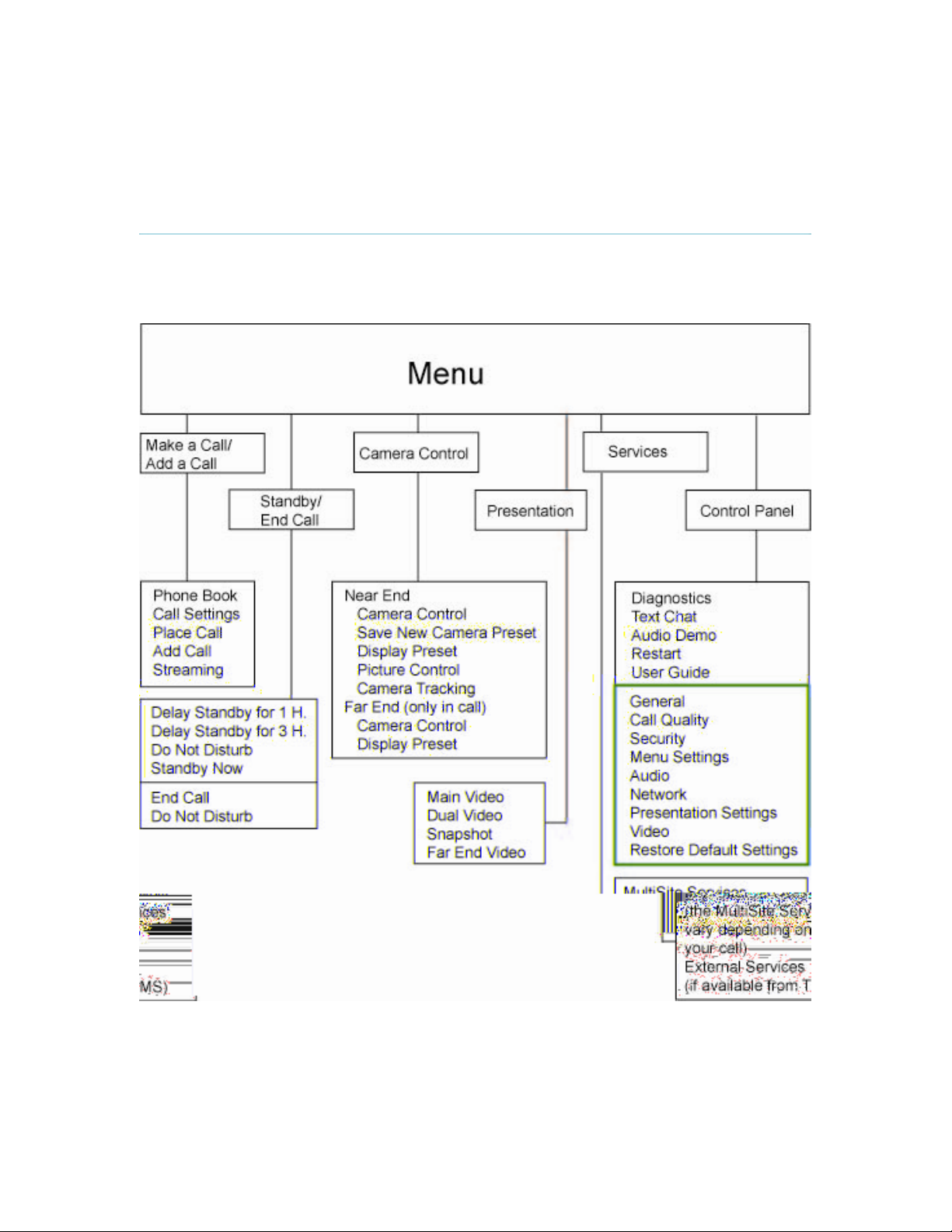
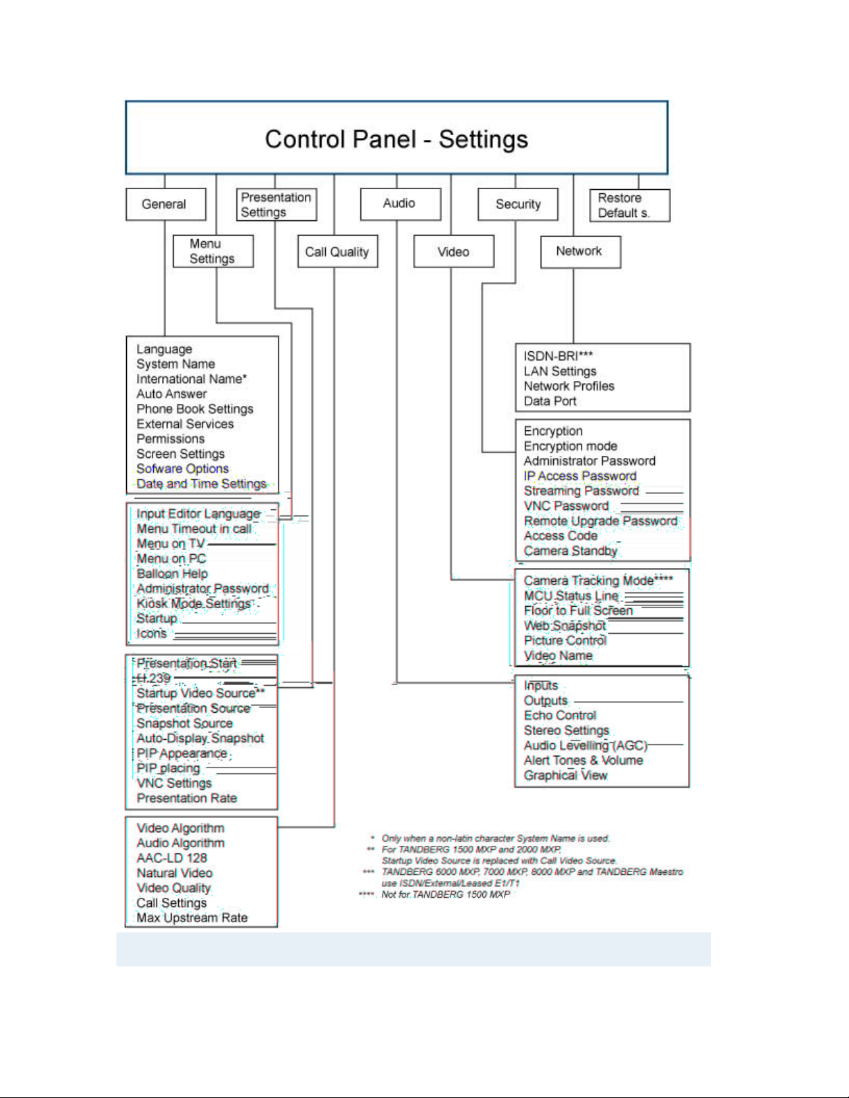
1.2 Menu Structure
The Menu is available for all users and contains all the functionality of the system. The Control
Panel contains all the settings of the system. Making changes to the settings will change the
behavior of the system. The menu structure is shown below.
22
Page 23
Installation
Note that the system features and menu settings may vary depending on network selection
and software package.
23
Page 24

TANDBERG Maestro MXP
2 Installation
Precautions:
Never install communication wiring during a lightning storm.
Never install jacks for communication cables in wet locations unless the jack is
specifically designed for wet locations.
Never touch uninstalled communication wires or terminals unle ss the telephone line has
been disconnected at the network interface.
Use caution when installing or modifying communication lines.
Avoid using communication equipment (other than a cordless type) during an electrical
storm. There may be a remote risk of electrical shock from lightning.
Do not use the communication equipment to report a gas leak in the vicinity of the leak.
Always connect the product to an earthed socket outlet.
The socket outlet shall be installed near to the equipment and shall be easily accessible.
Never install cables without first switching the power OFF.
1TR6 network type is not approved for connection directly to the telecommunications
network. This network type is only to be used behind a PABX.
X.21 network type is not approved for connection directly to the telecommunications
network. This network type is only to be used together with already approved equipment,
and is not meant for direct connections to the telecommunication networks.
V.35/RS-449/RS-366 network type is not approved for connection directly to the
telecommunications network. This network type is only to be used together with already
approved equipment, and is not intended for direct connection to the telecommunication
networks.
This product complies with directives: LVD 73/23/EC, EMC 89/366/EEC, R&TTE 99/5/EEC
24
Page 25
2.1 Unpacking and Mounting
Installation
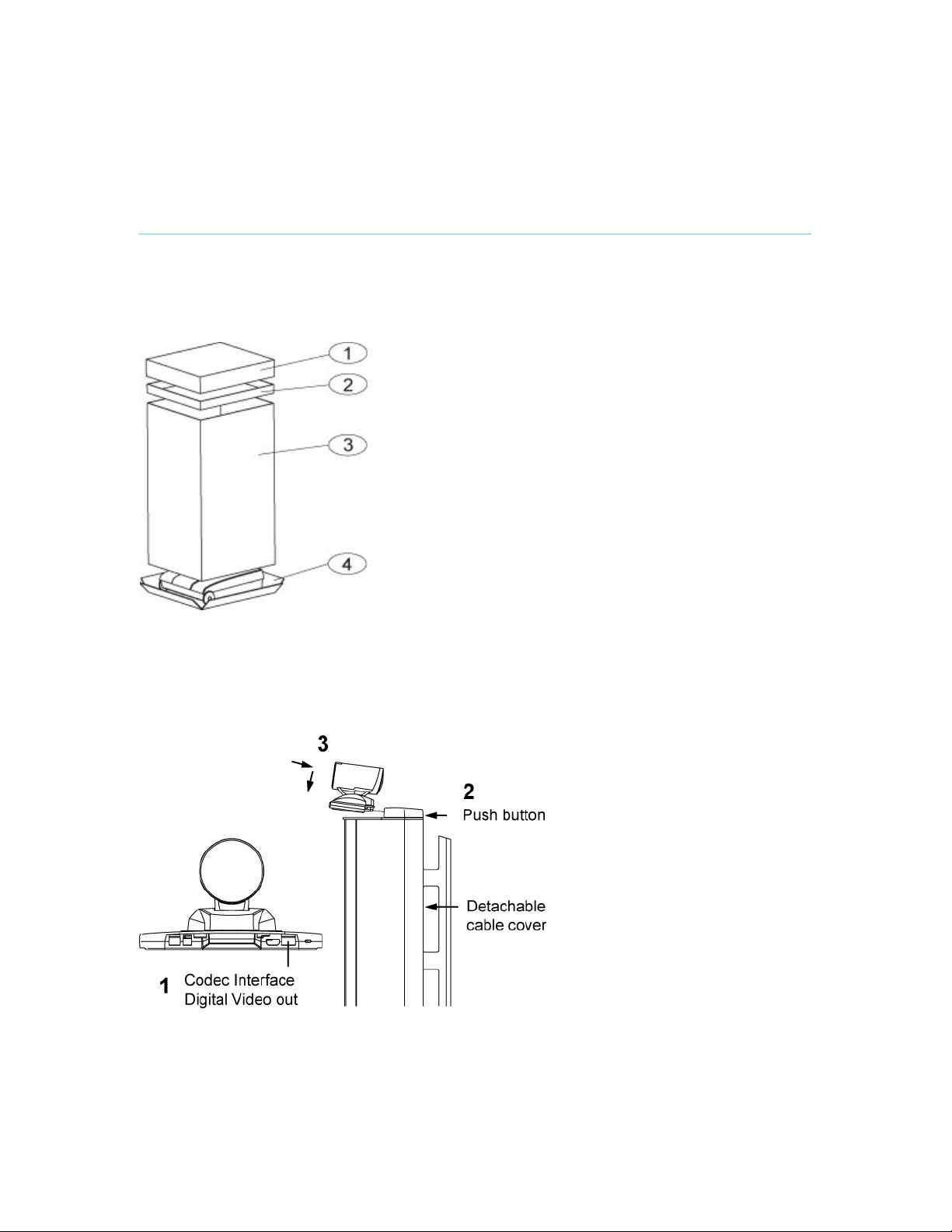
1 Unpacking
The TANDBERG Maestro is delivered in one transport case with all components inside. Remo ve
the case in the order shown on Figure 1.
The accessories box contains:
TANDBERG Precision HD Camera
2x Table Microphones
Remote Control and Tracker with batteries
Documentation
Cables for external displays
Figure 1
2 Mounting of the camera
Mount the camera as shown in figure 2.
Figure 2
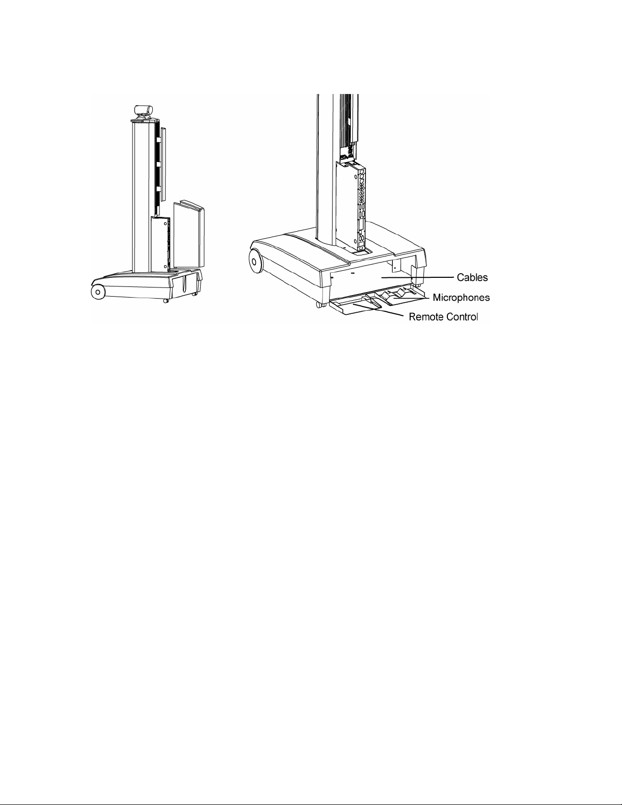
3 Open the back of the system
For access to the cables, microphones and remote control, remove the back cover as shown in
Figure 3. The codec cover and the back cover are both held in place by magnets.
25
Page 26
TANDBERG Maestro MXP
Figure 3
26
Page 27
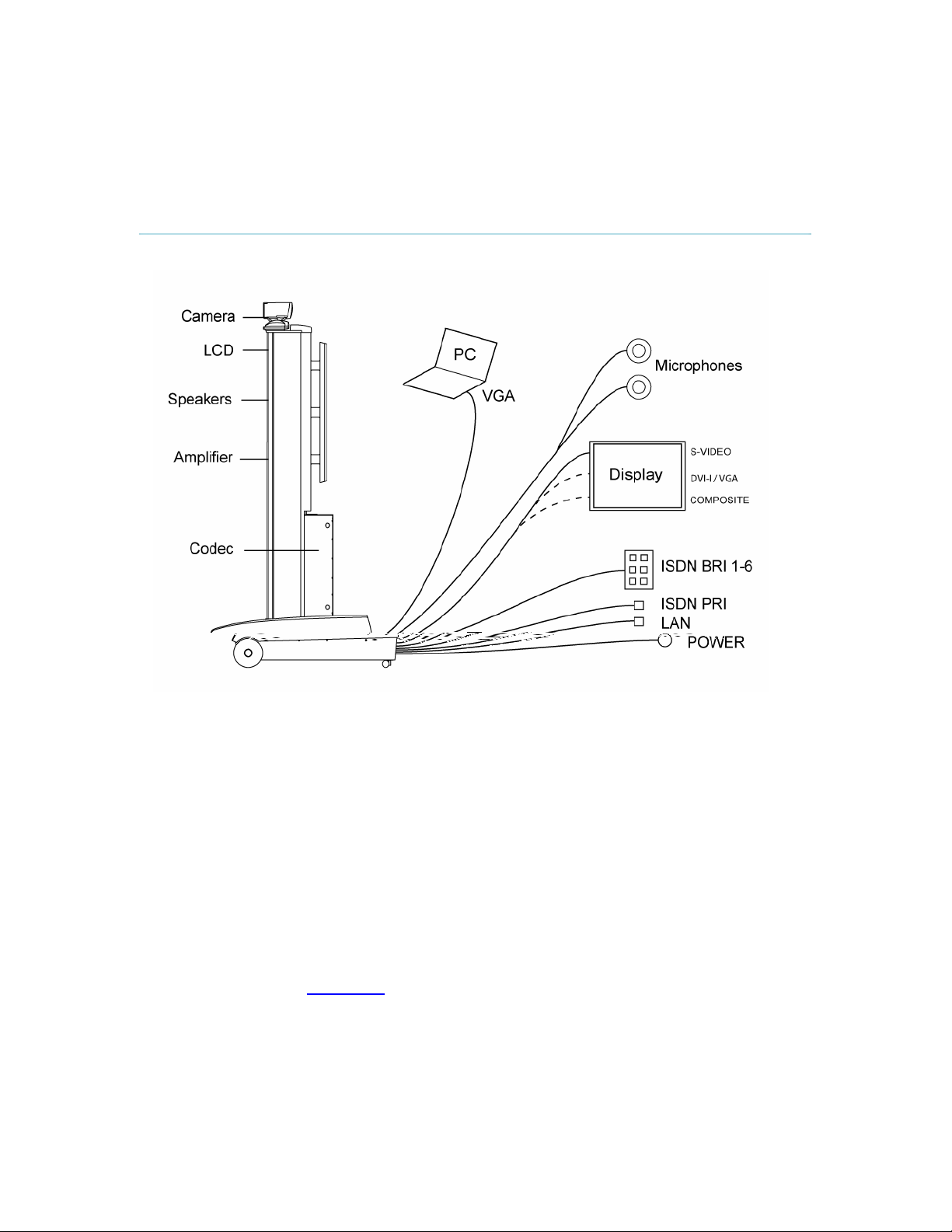
2.2 Connecting Cables
Installation
1. Power cable
Find the right power cable that works for your country in the accessories box, and connect to
power cable from base, and to an electrical distribution socket.
2. Microphone cable
Connect the microphone cable to the microphone.
3. a) ISDN BRI
Connect the ISDN cables to the ISDN sockets (S/T interface) provided by the network provider.
The main ISDN number will be that number associated with the socket to which ISDN cable
number 1 has been connected.
3. b) ISDN PRI
If using the PRI interface, the E1/T1 cable should be connected to a CSU (Channel Service
Unit). It is recommended that a CSU is used between the system and the PRI line from the
network provider, see Appendix 8
4. LAN cable
To connect the system to a Local Area Network (LAN), connect the cable labeled "LAN
Ethernet" to a suitable Ethernet port on the LAN.
5. External Display device
.
27
Page 28

TANDBERG Maestro MXP
a. S-video – connect cable from Codec Video Out 1 to External display
b. DVI-I / VGA – find cable in accessories box and connect cable from DVI-I out single
on the Codec to external display
c. Composite – find cable in accessories box and connect cable from Video out 4 on the
Codec to external display
6. PC
Connect cable from DVI-I in PC from the Codec to PC.
28
Page 29

2.3 Monitor Configuration
Installation
Configuration of external display (projector)
Select 16:9 or 4:3 format on the projector.
Make sure that the main projector is connected to the DVI-I Single output on the codec.
Please refer to the projector user manual for further information.
29
Page 30

TANDBERG Maestro MXP
2.4 System Configuration
The system must be configured for each installation. Configuration settings can be made via the
system menu. If an external IMUX or non-standard network is being used it may be necessary to
configure any associated external equipment.
Navigate through the menu system using the arrow keys and OK. Remember to press the Save
button on the bottom of each menu to save the changes. Press Cancel (x) to return to the
previous Menu. See General Use
remote control.
General configuration:
1. Open the General Settings menu
Press OK/Menu to open the Menu, if not already displayed. Select Control Panel General to open the General Settings menu.
for more information about how to use the menus and the
30
2. Language
Press OK in the Language field and select the desired language from the list.
3. System Name / International Name*
Enter a name in the System Name field using the number keys on the remote control,
in the same way as with a mobile or cellular phone. Hold down the # key for one
second to switch back and forth from numbers to alpha characters.
4. Auto Answer, Phone Book Settings, External Services Settings and
Permissions
These settings may be left unchanged if no special needs are required. See chapter
General Settings
for more information.
Page 31

5. Screen Settings
When using wide screen (16:9) monitors, set TV Monitor Format to Wide (16:9).
TANDBERG also recommends setting Picture Layout to Picture outside Picture when
using 16:9 monitors. Picture outside Picture provides a display layout optimized for
wide screen monitors. The display layout may be changed at any time using the
Layout button on the remote control.
6. Software Options
To activate options for the system, a new option key must be entered in the Software
Options menu (see paperwork accompanying the system). The Presenter option key
should be entered under “New Option Key”. Any bandwidth option key should be
entered under “New Bandwidth Key”. For more information on these options, please
contact your TANDBERG representative.
7. Date and Time Settings
Select your preferred Date and Time Settings.
8. Save changes
Remember to save any changes made in a menu by selecting the Save button on the
menu line and pressing OK.
Network configuration:
1. Open the Network menu
Press OK/Menu to open the Menu, if not already displayed. Select Control Panel Network to open the Network menu.
Installation
2. ISDN configuration
Set the Network type to the desired network. Specify the settings for the selected
network in the relevant menu. Enabled but unused ISDN lines (i.e. lines not active)
should be disabled. For details, follow the instructions in ISDN /External/Leased
E1/T1. See also the examples in Appendix 9: Connecting the system to the Switched
56 network and in Appendix 10: Connecting the system to ISDN using NT1 network
adapters.
3. LAN configuration
Select LAN Settings in the Network menu and specify the necessary LAN settings
according to the instructions from your LAN administrator. For details, follow the
instructions in LAN Settings
refer to H.323 Settings
. If there is an H.323 Gatekeeper present on your LAN,
as well.
31
Page 32

TANDBERG Maestro MXP
4. Network Profiles
Please refer to Network Profiles
for details
5. Data Port
Please refer to Data Port
for details
6. Save changes
Remember to save any changes made in the menu by selecting the Save button on
the Menu line and pressing OK.
* The International Name field is only visible if the system name contains Asian and non-Latin
character text input.
32
Page 33

3 General Use
Wake up the system
When the system is not in use, it is in standby mode and the screens are black. Wake up the
system by picking up the remote control. An incoming call or pressing any key on the remote
control will also wake up the system.
If the system does not respond:
Make sure that the system is switched on. The red light indicator below the internal LCD
should be turned on to indicate power on the system. If the system is not switched on,
you need to remove the codec cover on the rear of the pedestal in order to access the
power switch. Pull and lift the cover. The power switch is at the bottom of the Codec.
If the picture does not appear on your external display, but on the 5’’ internal LCD:
Check that the external display is turned on.
Check that video cable from Maestro is connected to external display
Make sure that the video settings on the external display are correct, read the user
manual for the external display.
Page 34

TANDBERG Maestro MXP
3.1 The Welcome Screen
When the system is switched on, the welcome screen will be displayed. The welcome screen
presents the menu and displays your main camera image in the background (display main
camera is the default setting). The ISDN/IP numbers and the system name are displayed in the
upper right corner. The ISDN Number and IP Number are the dial-in numbers of the system.
The welcome screen provides you with the most important system information:
System Name
Your ISDN Number
Your IP Address or IP Number
Indications of Missed Calls
It is possible to customize the text on the welcome screen. See Menu Settings
welcome text.
or Warnings if any
for how to edit the
34
Page 35

Administrator Settings
3.2 Using the Remote Control
The system is controlled with a remote control. Think of the remote control as a mobile phone
with number keys and call keys. Use the arrow keys and press OK to navigate through the
menus. The system’s most commonly used functions are also accessible directly from the remote
control. The Infra Red (IR) sensor for the remote control is located in front of the Camera. There
is also a second IR-sensor located in the front of the Codec itself, which will be automatically
enabled if the Camera is not connected.
The remote control (TRC 3)
1. Mic Off turns your microphone on and
off, see Mic off
2. Arrow keys are used for navigation in
the menu and for moving the camera*
when the menu is hidden, see
Navigation
3. Volume + and – adjusts the Codec
volume only and not the monitor's
volume, see Volume + and -
4. The Layout key toggles between full
screen and different display layouts, see
.
Layout
5. Cancel takes you back one step in the
menu system. Use Cancel to delete
characters in an input field, see
Navigation
key for 1 second to close the menu.
6. Press the Call key to place a call, see
Make a Call
7. Camera presets define specific camera
positions. Move the camera to the
desired position and press and hold a
number key for 1 second to save the
current camera position to that number
key. To activate a preset whilst in a call,
simply press and release that number
key, see Camera Presets
8. Snapshot takes a snapshot of your video
only while you are in a call, see Take
New Snapshot.
9. The Presentation key switches to a
predefined presentation source. If the
Presentation key is held down for 1
second then the Presentation video
sources menu will appear, see
Presentation Key
10. Press OK/Menu to show the menu and
to select menu items, see Navigation
.
.
.
. Press and hold the Cancel
.
.
.
.
35
Page 36

TANDBERG Maestro MXP
11. Use Zoom + and – to zoom the camera
12. Selfview displays your outgoing video.
13. Use the Phone Book to store and recall
14. Use the red End Call key to end the
15. Number/Letter keys function in the same
16. Press Touch tones when you are in a
*This does not apply to all systems with small integrated cameras.
in and out.*
Press Selfview again to turn selfview off,
see Selfview
.
video contacts for easy placement of
calls, see Phone Book
.
current call. Pressing this key when not
in a call will place the system in Standby
mode, see End Call
and Standby.
manner as with a mobile or cellular
phone, see Number and Letter keys
.
call and need to dial extension numbers
etc. (instead of presets). Press the
OK/Menu button to exit Touch Tones,
see Touch tones
.
36
Page 37

The remote control (TRC 4)**:
Administrator Settings
1. Change video source. If
possible, you will start open a
Dual Stream. Press the video
source button again to stop
the dual stream.
2. Mic Off turns your microphone
on and off, see Mic off
.
3. Arrow keys are used for
navigation in the menu and for
moving the camera* when the
menu is hidden, see
Navigation
.
4. Volume + and – adjusts the
Codec volume only and not
the monitor's volume, see
Volume + and -
.
5. The Layout key toggles
between full screen and
different display layouts, see
Layout
.
6. Cancel takes you back one
step in the menu system. Use
Cancel to delete characters in
an input field, see Navigation
.
Press and hold the Cancel
key for 1 second to close the
menu.
7. Press the Call key to place a
call, see Make a Call
.
8. Number/Letter keys function
in the same manner as with a
mobile or cellular phone, see
Number and Letter keys
.
Camera presets define
specific camera positions.
Move the camera to the
desired position and press
and hold a number key for 1
second to save the current
camera position to that
number key. To activate a
preset whilst in a call, simply
press and release that
number key, see Camera
Presets.
9. Press Preset + a number to
activate a preset.
10. Press the Services button to
open the Services menu.
11. The Presentation key
switches to a predefined
37
Page 38

TANDBERG Maestro MXP
*This does not apply to all systems with small integrated cameras.
** Ordered separately
presentation source. If the
Presentation key is held down
for 1 second then the
Presentation video sources
menu will appear, see
Presentation Key
.
12. Press OK/Menu to show the
menu and to select menu
items, see Navigation
.
13. Use Zoom + and – to zoom
the camera in and out.*
14. Selfview displays your
outgoing video. Press
Selfview again to turn selfview
off, see Selfview
.
15. Use the Phone Book to store
and recall video contacts for
easy placement of calls, see
Phone Book
.
16. Use the red End Call key to
end the current call. Pressing
this key when not in a call will
place the system in Standby
mode, see End Call
Standby
.
and
17. Snapshot takes a snapshot of
your video only while you are
in a call, see Take New
Snapshot.
18. Press Touch tones when you
are in a call and need to dial
extension numbers etc.
(instead of presets). Press the
OK/Menu button to exit Touch
Tones, see Touch tones
.
19. Pressing Far End turns Far
End control on and off.
20. Press the Help button to open
the User Guide menu.
38
Page 39

3.2.1 Navigation
Administrator Settings
Arrow keys and OK
Navigate in the menu with the arrow keys on the remote control. The
orange selector on screen shows the selected item. Press OK to select.
Cancel key
In the Menu, pressing Cancel (X) will hide the menu. If the menu is hidden,
bring it back with OK. In other menus, pressing Cancel (X) takes you one
step back. In an input field, pressing Cancel (X) will delete
characters/numbers to the left.
Back/Cancel button
The X button in the menu corresponds with the X key on the remote.
39
Page 40

TANDBERG Maestro MXP
3.2.2 Selfview
The term “Selfview” means the outgoing image. In a normal call using the main camera, this is
the image of yourself. The Selfview button toggles the images between Far End, Selfview and
Dual Video (if any).
How to use Selfview:
1. Outside a call, pressing the Selfview button will switch between the near end video and a
black screen/logo on the main monitor.
2. In a point to point call, press the Selfview button once to switch from far end video to near
end video to see a full screen picture of the outgoing video. Press Selfview again to go
back to normal.
3. In a point to point call with a dual video stream, the dual stream is displayed in the big
picture. Press the Selfview button to toggle to the Near End picture, then the Far End
picture, and finally back to the dual stream.
The above behavior is similar for both single monitor systems and dual monitor systems. Selfview
applies to the main monitor.
3.2.2.1 Local PC Display
When using the screen as your PC screen, it is recommended to set Local PC Display to On, see
Screen Settings
and you can keep on working without having the Far End participant viewing your PC screen.
Note that this applies to single monitor systems only.
It is also recommended to keep the Auto Layout setting On (default) to get a suitable layout when
toggling from Local PC Display mode to standard conference mode.
Use the Selfview button to toggle between Local PC Display mode and standard videoconference
mode. An indicator tells you that your PC image is displayed locally.
. That implies that you can display your PC locally while having a video meeting
40
Page 41

Administrator Settings
Example:
You are using the system as a PC and get an incoming call.
When the setting “Use Screen as Local PC monitor” is On, you will keep your PC image
displayed locally and the incoming call pops up in a PIP or as smaller images in a 1+3
layout, depending on your system. You will see Local PC displayed in the big picture
and Far End and/or Near End (your self) displayed in smaller pictures.
Press the Selfview button to switch to standard conference mode. The Local PC image
is no longer displayed and Far End is displayed in the big picture or full screen. Press
Selfview again to see Near End. Pressing Selfview a third time will bring back the Local
PC display mode.
41
Page 42

TANDBERG Maestro MXP
3.2.3 Picture Layout
The layout of the screen can either be shown as Picture in Picture (PIP) or Picture outside Picture
(POP) when displaying more than one video image. The behavior of the Layout button is
dependent on the Picture Layout setting in Screen Settings
.
3.2.3.1 Picture in Picture
When Picture Layout is set to PIP, the Layout button makes it possible to see a second image in
a smaller view in one of the corners of the screen. The second image will be placed on top of the
main image. The user can decide in which corner the second image is to be displayed.
3.2.3.2 Picture outside Picture
When Picture Layout is set to POP, the Layout button makes it possible to see up to three images
in a composition optimized for wide screens. The second image can be displayed either as a
side-by-side the main image (1+1) or smaller images next to the main image (1+2 and 1+3).
Press the Layout button once to get side-by-side view (1+1). Press again to get the layouts 1+2
and 1+3, and finally go back to full screen view. You can also go back to full screen directly by
pressing and holding Layout for 1 second. It is recommended to use Picture outside Picture for
wide screen monitor systems.
3.2.3.3 Auto Layout
The system will automatically choose the best layout for your call. The layouts vary depending on
how many participants there are and if you use a dual video source or not. You can however
always change layout manually with the Layout button. Auto Layout applies when you open or
close a dual stream, or add or disconnect participants.
Auto Layout also includes the former automatic PIP. That implies that PIP will automatically be
shown when suitable, e.g. to display selfview when you move your near end camera. The
automatic PIP times out after a couple of seconds.
If Auto Layout is Off you will get no automatic layout changes during a call and the user must
manually control the images with the Layout button. Auto Layout is default On. To turn Auto
Layout Off, go to Screen Settings
.
42
Page 43

3.2.4 Mic Off
Administrator Settings
To mute the microphone during a call, press the Mic off button. An on-screen indicator appears in
the upper right corner when the microphone is off. In a call, if audio is detected, the on-screen
symbol will start to flash. Pressing the Mic off button one more time will activate the microphone
again.
A green LED below the internal LCD at the system will be turned on when the microphone is off.
Note that Mic off will mute all microphone inputs and audio 4 input.
When an incoming call is answered, the microphone may be in the off state because the Auto
Answer setting is On+Mic off, see Auto Answer. The icon will start to flash when you start
speaking. Remember to turn the microphone on before a meeting.
43
Page 44

TANDBERG Maestro MXP
3.2.5 Volume + and -
Press the Volume key to adjust the volume level. An on-screen indicator will show the current
level.
44
Page 45

3.2.6 Number and Letter keys
Administrator Settings
Pressing a number key when outside a call will bring up the call menu. When in a call, the
number keys are used for Camera Presets. Press a number and go to the corresponding Camera
Preset (see Camera Presets
required, the system automatically goes to number mode and numbers can be dialed with the
number keys as usual.
When accessing an input field where letters are required, the system automatically goes to letter
mode. Writing letters works like on a mobile phone. Press the key that corresponds to your
desired letter. Press the key as many times as needed to get the right letter. Change to lower or
back to upper case letters with the a/A key, and space with the 0 _ key.
To write numbers in a text input field, press the button through all the letters. Press once more
and the number will appear.
Example: How to write "System 123" in the System Name input field:
Press the 7-key four times to get an "S".
Press the #-key once to switch between upper case and lower case letters.
Press the 9-key three times to get a "y".
Press the 7-key four times to get an "s".
Press the 8-key once to get a "t".
Press the 3-key twice to get an "e".
Press the 6-key once to get an "m".
Press the 0-key once to get space.
Press the 1-key three times to get a "1".
Press the 2-key four times to get a "2".
Press the 3-key four times to get a "3".
). However, when accessing an input field where numbers are
45
Page 46

TANDBERG Maestro MXP
3.2.7 Touch Tones
To activate dialing touch tones during a call, press the Touch tones button. Otherwise the number
keys will work as configured in the Number Key Mode, see Control Panel – Menu Settings –
Number Key Mode. An indicator will let you know that Touch tones are enabled. Finish with OK to
exit Touch tone mode.
46
Page 47

Administrator Settings
3.2.8 Presets and Extension Numbers
When pressing a number key on the remote control, while in a call, the user can decide what
shall happen. The system can be configured to act automatic or manual.
While in a call, the user presses a number key to:
• add another call
• dial extension numbers
• use camera presets
Setting Number Key to Automatic:
Some users want the camera presets as the default action when pressing a number key, when in
a call. The number keys can be configured to always act like this; or to act in accordance to any
of the other available choices.
Setting Number Key to Manual:
Sometimes, when you are in a call, you need to switch between adding another call, dial
extension numbers or use camera presets. Then you would want the system to give you a choice
of what to do. If you configure the Number Key Mode to Manual you can select the preferred
action when pressing a number key.
For more information about Number Key Mode, please see Control Panel - Menu Settings –
Number Key Mode.
47
Page 48

TANDBERG Maestro MXP
3.3 On-screen Indicators
The system has a number of icons signaling different settings:
Microphone Off
This indicator is shown when the microphone is turned off. Press the Mic off
button again to turn the microphone back on, see Mic Off
Volume Off
This indicator is shown when the volume is turned off. Press Volume + to turn the
volume back on, see Volume + and -
Secure Conference, AES
This double padlock indicator is shown when AES encryption (Secure
Conference) is active, see Security
Secure Conference, DES
This padlock indicator is shown when DES encryption (Secure Conference) is
active, see Security
Not Secure Conference
This open padlock indicator is shown during the initialization phase for AES or
DES encryption. During this period the call is not secure, see Security
Warning
This indicates that the system has detected a warning. Select the icon and press
OK to see details on the warning. Please see Warnings
warnings.
Bad Network
This indicator appears if the system detects network anomalies like packet loss
(5%), jitter (200ms) etc., during a call. Open the menu by pressing the OK/Menu
button and select the warnings icon too see details.
Floor
This indicator is shown when you are displayed in full screen in a multipoint
conference, see Request Floor and Release Floor
for details.
for details.
for details.
for details.
for details.
for details.
for a list of possible
48
Page 49

Administrator Settings
Telephone
This indicates that there is a telephone participant in the conference. The
displayed number indicates how many telephone participants there are in the
conference.
Duo Video / H.239
This indicates that there is a Dual Video Stream sent from you (near end). The
feature Duo Video / H239 allows participants at the far end to simultaneously
watch a presenter on one screen and a live presentation on the adjoining screen.
49
Page 50

TANDBERG Maestro MXP
3.4 Using the Menu
Menu outside a call
Menu when in a call.
Press the Menu button on the remote control to display the menu. The menu contains all
functions needed in order to control the system.
50
Page 51

Administrator Settings
The menu contains the following items:
Make a Call
Standby
Camera Control
Presentation
Conference Services
Control Panel
/Add Another Call
/End Call
Close
See Menu Structure
for a full overview of the menu.
The functions of the menu are displayed as icons. The currently selected icon is marked by an
orange square, and the name of the corresponding function is displayed on the line above, see
the figure above.
Press the OK button to activate the currently selected function.
The menu automatically times out after 15 seconds if not used, see Menu timeout
. Press the
Menu button to bring it back. It is also possible to hide the menu manually by pressing the Cancel
button on the remote control or select the Close icon in the menu.
* Systems with no Camera Control icon available may have a Far End Control icon present when in a call and Far End
Control is possible.
51
Page 52

TANDBERG Maestro MXP
3.5 Make a Call
It is easy to make a call:
1. Press the green Call button on remote control and Dial number
2. Press the green Call button again to initiate the call
Display the call menu by either:
1. Select Make a Call from the menu, or
2. Press the green Call button on the remote control
The TANDBERG system can make both Video calls
Call Settings
current call if required. The Default Call Settings are defined in Control Panel - Call Quality -
Default Call Settings
It is possible to start Streaming
specifies the quality of the call. It is possible to alter the default call settings for the
.
from this menu.
and Telephone calls.
For setting up a MultiSite conference, see Add Call for more details.
• If the system has an embedded MCU (Multipoint Control Unit) you can set up a Multisite
conference.
The Phonebook and Call Type Selector icons are placed to the right of the Dial Number entry
field.
52
Page 53

3.5.1 Place a Call
Administrator Settings
The TANDBERG system can make both Video calls
button is placed to the right of the number entry field. The button shows if it is a video call
(default) or a telephone call. Press the button to show a drop down list to select the type of call.
Display the Call menu by either:
1. Select Make a Call from the menu, or
2. Press the green Call button on the remote control
In the Call menu, enter the Dial Number either:
1. Manually, or
2. Select the book symbol in order to display the Phone Book
participant.
Select type of Call – Telephone Call or Video Call
1. If you are dialing manually you might need to change the type of call. A button to the right
of the entry field shows if you have a telephone call or a video call. This button is called
the Call Type Selector.
2. Click on the Call Type Selector to the left of the entry field and press OK to see the
options. Select the type of call, Video Call or Telephone Call and press OK.
and Telephone calls. A Call Type selector
and select a conference
When dialing manually, toggle between ABC/abc by pressing the # button on the remote control
and between abc/123 by holding the # button for one second. For IP addresses, use a star as
separator in the IP addresses.
If you are making a video call and the system is registered on a gatekeeper or border controller
with DNS support, there are several ways to call into the system:
<IP address>
<E.164>
<H.323 ID>
<H.323 ID>@<domain>
<E.164>@<domain>
<H.323 ID>@<IP address>
<E.164>@<IP address>
See H.323 Settings
for details.
53
Page 54

TANDBERG Maestro MXP
Place the call by either:
1. Use the arrow button on the remote control to select the Place Call icon and press OK, or
2. Press the green call button on the remote control.
TIP: When dialing a telephone number and pressing the green Call button on the remote control,
the system will in most cases automatically interpret the number as a video number and not a
telephone number. The interpretation can sometimes take a little while and it is faster to use the
Call Type Selector button in the menu.
54
Page 55

3.5.2 Add Call
Administrator Settings
(Optional feature)
Conference systems with built-in MultiSite can handle up to 6 video calls and 5 telephone calls
simultaneously.
It is possible to both set up a conference with many participants and also add part i cipants during
a conference.
Set up a conference with two or more participants
Display the Call menu by either:
1. Select Make a Call from the menu, or
2. Press the green Call button on the remote control
Add participant(s) to the conference:
1. Select the Add Call icon and press OK.
2. Dial Number manually, or
3. Select the book symbol in order to display the Phone Book and select a conference
participant, see Phone Book
entry, see New MultiSite Contact
TIP: Set up a list of all the wanted conference participants by selecting the Add Call the desired
number of times, and enter their numbers afterwards.
Select the Call Type – Telephone Call or Video Call
1. If you are dialing manually you might need to change the type of call. A button to the right
of the entry field shows if you have a telephone call or a video call. This button is called
the Call Type Selector.
2. Click on the Call Type Selector and press OK to see the options. Select the type of call,
Video Call or Telephone Call and press OK.
Start Multisite conference:
1. When all participants have been added to the list, press OK button on remote control or
select the Place Call icon on the menu to start the Multisite conference.
Add participant(s) during a conference:
1. Display the Call menu during a call and select Add Another Call from the menu, or the
green Call button on the remote control.
2. Enter new participants in the same way as described above.
for details. It is also possible to select a predefined MultiSite
. Press OK on the remote control.
55
Page 56

TANDBERG Maestro MXP
3.5.3 Call Settings
The Call Settings specifies the quality of the call. Each call will be set up with the Default Call
Settings if the settings are not altered. Usually it is not necessary for the user to alter the settings.
The Call Settings are defined in Control Panel - Call Quality - Default Call Settings.
When setting up a call in the Make a Call menu:
1. Select the Call Settings
control.
2. Make desired changes to Network, Bandwidth and Restrict (56k). If this is to be the new
default call settings, select Set as Default in the menu.
3. Select the OK icon and press the OK button on the remote control.
field for the participant and press the OK button on the remote
It is possible to make the changes made to the Call Settings
and OK. These settings will now be the default settings for all future manually dialed calls.
These settings are also available in the menu Control Panel - Call Quality - Default Call Settings.
56
default by selecting Set as Default
Page 57

Administrator Settings
3.5.4 SIP Services
SIP enables you to use the features Add Call and Transfer even if your system doesn’t have
multipoint capabilities. To get the SIP Services available, you have to make a call using SIP as
your Net. (See Call Settings)
3.5.4.1 Add Call
You can add another call to your existing SIP call.
How to Add another Call:
1) Open the menu by pressing OK (if it is not already open).
2) Press Add another Call or press the green button on the remote to open the Call menu.
3) Dial number of your next call. Press Place Call or press the green key on the remote
control to connect the call.
4) The second call connects. The menu displays an icon below the menu line to indicate
that you have a call waiting.
3.5.4.2 Transfer
It is possible to transfer your call to another number.
How to Transfer a point to point call:
1) Open the menu by pressing OK (if it is not already open).
2) Press Add another Call or press the green button on the remote control to open the Call
menu.
3) Dial the number of the person you would like to transfer your call to.
4) Choose the Transfer Call button and press OK. Your call is transferred.
57
Page 58

TANDBERG Maestro MXP
3.5.5 Streaming
Streaming lets you broadcast your meeting to participants on the web. The web participants can
listen to the meeting, see snapshots, but not participate themselves. Snapshots of current stream
(if MultiSite), selfview, far end and DuoVideo streams are accessible via http. See Appendix 6
descriptions of the possible snapshot files.
How to use Streaming:
1. Choose Streaming from the Call Menu to open the Streaming menu.
2. Press Start Streaming from the menu line. An indicator will appear on the screen when
streaming is activated.
3. Press Stop Streaming to end streaming. Streaming will also end when you disconnect the
call.
4. Press Streaming Settings if you want to change streaming settings (see Streaming
Settings below)
How to view streaming from a PC:
1. After streaming is started, an easy way to view the streamed audio/video is to start your
Web browser and enter the IP-address of the streaming system.
2. After the Web page of the system is shown, click on Streaming. Alternatively, enter
http://<codec/ip-address>/showstream.ssi
Streaming Settings
Address
Address Port
TTL/Router
Hops
Streaming
Address is defined as the IP-address of a streaming client, streaming
server or a multicast address. Giving an address in the range 224.0.0.1-
239.255.255.255 will broadcast the stream to any host that has joined
the specified multicast group. Specifying normal broadcast address
255.255.255.255 will broadcast to any members on the LAN.
If several codec’s are streaming to the same IP-address, different ports
have to be used in order for the client to know which stream to receive.
If the first codec streams on port 2240 and the second codec on port
2250, the client has to specify which port to listen to. Video is
transmitted on the specified port; audio is transmitted on the port
number 4 greater than the specified video port, in this case 2244 and
2254.
This is used for streaming data to limit how many routers the data
should pass before it is rejected. If TTL is set to 2, data will not traverse
more than 2 router hops.
Auto: Enables streaming of both local and far end video.
for
58
Page 59

Administrator Settings
Source*
Selection of which site to be streamed is done using voice
switching (the site that speaks is streamed).
Local: Only the local video will be streamed.
Remote: Only the far end video will be streamed.
Local and far end audio is always streamed.
Allow Remote
Start
On: Streaming can be started from external user interfaces like
the Web-browser or Telnet session.
Off: Streaming can only be started from the Video System User
Interface using the remote control, or by using the Data port.
This will prevent activation of streaming using Web browser or
Telnet sessions. See also Password section below
Announcements
On: The codec will send announcement packets to the network
that it is streaming. This enables a streaming client (e.g. a PC)
to connect to the codec’s streaming session. Used by Cisco
IP/TV.
Off: No announcement packets will be transmitted.
Video Rate
Defines the Video streaming rate from the system. Range is 16 kbps 320 kbps. In addition, audio (G.711) streaming rate is 64 kbps, providing
a maximum streaming rate of 384 kbps.
Streaming
Password
Set password so that only participants entering correct password will be
able to view the streaming session. Entering a password will prevent
unauthorized people from accessing the streaming session.
*The streaming source setting is not available when streaming only is supported outside a call.
59
Page 60

TANDBERG Maestro MXP
3.5.6 Dialing In From Outside the Enterprise
Dialing in Without Being Registered to a TANDBERG Gatekeeper
The feature enhancement enables dialing through a TANDBERG Gatekeeper without being
registered to it. This makes it easy to call in from a video system outside the enterprise.
It's done by dialing: EndPointAlias@GatekeeperAddress[:Port] where:
EndPointAlias: is the alias of the endpoint you want to call, the endpoint you call must be
registered with this alias on the gatekeeper
GatekeeperAddress: is either the IP-address of the gatekeeper in the form a.b.c.d (or
IPv6 a:b:c:d:a:b:c:d) or the DNS name (A/AAAA or SRV record) of the gatekeeper.
Port: is optional and gives the Q.931 port to initiate the call. The port default is 1720 and
can in most cases be left out.
Currently the SRV records _h323cs._tcp. and _h323ts._tcp. are supported.
If using an IP-address, or if not specifying the port, the default is using the normal Q.931 with port
1720.
NOTE! To be able to make such a call, this feature must be enabled in your gatekeeper or border
controller, and the called endpoint must be registered with the enterprise gatekeeper or border
controller.
60
Page 61

3.6 Answer an incoming call
Administrator Settings
How to answer an incoming call:
To accept an incoming call, press the OK button or the green Call button on the remote
control.
How to reject an incoming call:
To reject an incoming call, select the Reject icon and press the OK button, or press the
End Call button on the remote control.
Incoming calls will connect automatically if Auto Answer is set to On, see Auto Answer
When idle, the system will accept all incoming calls as long as Incoming MCU Calls and Incoming
Telephone Calls are set to On, see Permissions
activated, see Do Not Disturb
for more details.
for details. Also, Do Not Disturb must not be
for details.
61
Page 62

TANDBERG Maestro MXP
3.7 End Call
How to end a call:
Press the red End Call button on the remote control, or
Press the Menu button on the remote control to display the menu and select End Call.
When the End Call dialog box is displayed either:
Press the red End Call button on the remote control again, or
Press the OK button to confirm that the call is to be ended.
How to end a MultiSite call:
In the list of participants:
Note that switching off the monitor(s), using the power button on the monitor, will not end a
call. Some systems come with monitors that are not possible to switch off.
62
Page 63

3.8 Standby
Administrator Settings
The system will automatically go to Standby mode when it is not in use. In standby mode, the
screen(s) are black. It is however still possible to receive incoming calls.
How to enter standby mode manually:
Select Standby from the menu and select Standby Now, or
Press the End Call button on the remote control twice.
How to exit standby mode:
When the system is in standby, pick up the remote control, or press any of its keys to
activate the system again.
The standby mode of the system should be enabled if the system is to be left idle.
Note! Standby is not activated by switching off the power to the monitor(s) (some systems
come with monitors that are not possible to switch off.). External displays like projectors
should be turned off when not in use.
When Camera Standby Mode is On
When Camera Standby mode is On, the camera turns away when standby is activated. When the
system is activated the camera turns back to normal position.
If the system is set for Use screen as Local PC monitor, see Screen Settings
mode will be disabled when the codec detects a video signal from the PC. If the PC video
signal is not detected, the standby mode will be re-enabled.
It is possible to postpone the system from entering standby mode for 1 hour or 3 hours, see Delay
Standby for 1 hour and Delay Standby for 3 hours.
, the Standby
63
Page 64

TANDBERG Maestro MXP
3.8.1 Delay Standby for 1 hour
Delay Standby for 1 hour postpones the system from entering standby mode for 1 hour.
This function is useful when using the monitors for a local presentation to prevent the system
from automatically blanking the monitors.
It is also possible to postpone the system from entering standby mode for 3 hours, see Delay
Standby for 3 hours.
64
Page 65

3.8.2 Delay Standby for 3 hours
Administrator Settings
Delay Standby for 3 hours postpones the automatic standby mode for 3 hours.
This function is useful when using the monitors for a local presentation to prevent the system
from automatically blanking the monitors.
It is also possible to postpone the system from entering standby mode for 1 hour, see Delay
Standby for 1 hour.
65
Page 66

TANDBERG Maestro MXP
3.8.3 Do Not Disturb
To prevent the system from accepting any incoming calls, activete the Do Not Disturb function.
The caller will hear a busy tone when calling the system. The monitor will be black when Do Not
Disturb is active, see figure below. This is useful when using the display for a presentation as
a local PC monitor and you do not wish any incoming calls during the presentation.
End Do Not Disturb by pressing any key on the remote control.
66
Page 67

3.9 Phone Book
Administrator Settings
The Phone Book is available via the Phone Book button on the remote control or from the Make a
Call menu.
Using the Phone Book is time saving and prevents the user from inadvertently calling the wrong
number. The contacts are sorted alphabetically. The contact names are displayed in the list and
the telephone or video numbers, bandwidth and net profiles of the selected contact are displ ayed
at the bottom line.
Navigate up and down in the Phone Book with the arrow keys on the remote control. Use the
letter keys to search through the contacts beginning with the typed letter.
Find names starting with a “C”:
• Press the 2-key three times to get a "C".
Find the name Charlie:
• Press the 2-key three times to get a "C".
• Press the 4-key two times to continue with a "h".
Remove letters by pressing the Cancel button on the remote control.
The Up One Level button brings you to the top of list and clears all letters typed.
The functions in the Phone Book are available when pressing the left arrow key on the remote
control, and then the up and down arrow keys. Note that the last selected contact will be marked.
When selecting Phone Book the phone book opens showing the folders Placed Calls, Missed
Calls, Received Calls and My Contacts. Global Contacts are listed below these folders.
67
Page 68

TANDBERG Maestro MXP
The following information is available from the Phone Book:
Placed Calls
Missed Calls
Received Calls
My Contacts
Global Contacts
68
Page 69

3.9.1 Call Log
Administrator Settings
The Call Log lists Placed Calls, Missed Calls and Received Calls. That allows the user to see
which calls that are made in the past. The lists contain a maximum of 30 numbers and the
numbers are stored in these lists until the system is restarted. If the contacts listed are available
in the phone book, the names will be displayed instead of the numbers.
Placed Calls lists all outgoing calls, Missed Calls lists the calls that are not accepted and
Received Calls lists all incoming calls. The calls in the lists are marked with these icons:
outgoing calls
incoming calls
missed calls
The following buttons are available from these folders :
Call Now
Copy to My Contacts
Delete
Delete All
Cancel
How to make a call using the call lists:
1. Select a number from the list.
2. Press the green Call button on the remote control, or press the left arrow key to select the
Call Now icon, followed by OK. The call will be set up as a video call or a telephone call
depending on the selected contact. Alternatively, press the OK button when the contact is
selected. The Make a Call menu will then be displayed with the name of the contact in
the Dial Number field, and the Call Settings field will reflect the call settings for this
contact. It is possible to alter the call settings before placing the call. The call will be set
up as a video call or a telephone call as described in Make a Call.
3. Wait for the call to connect.
How to delete numbers in the call lists do one of the following:
Choose the Delete button to delete a selected contact from the call list.
Choose the Delete All button to delete all contacts listed in the call list.
Note that you will not delete contacts from the Phone Book if you delete them from the call lists.
69
Page 70

TANDBERG Maestro MXP
3.9.2 My Contacts
My Contacts are the locally stored contacts on the system. This means that it is possible to add
new contacts and edit or delete existing contacts. My Contacts can store up to 200 contacts.
How to make a call using My Contacts:
1. Find the desired contact using the arrow keys or searching on the first letter with the letter
keys.
2. Press the green Call button on the remote control, or press the left arrow key to select the
Call Now icon, followed by OK. The call will be set up as a video call or a telephone call
depending on the settings made when storing the contact. Alternatively, press the OK
button when the contact is selected. The Make a Call menu will then be displayed with
the name of the contact in the Dial Number field, and the Call Settings field will reflect the
call settings for this contact. It is possible to alter the call settings before placing the call.
The call will be set up as a video call or a telephone call as described in Make a Call
3. Wait for the call to connect.
.
Note that the telephone or video number and profile of the selected contact are displayed on
the bottom line.
70
Page 71

The following functions are available from My Contacts:
Call Now
New Contact
New MultiSite Contact
Edit Contact
Delete Contact
Close
Administrator Settings
71
Page 72

TANDBERG Maestro MXP
3.9.2.1 Add New Contact
The New Contact function is available from My Contacts
Add a new contact to My Contacts by:
1. Select the New Contacts button to open the New Contacts dialog box.
2. Enter Name by using the letter keys on the remote control. Input will automatically be
interpreted as letters. Toggle between capital letters and small letters by pressing the #
button on the remote control. The maximum name length is 30 characters. For numbers,
press the # button for one second.
3. Enter Number by using the number keys on the remote control. Input will automatically be
interpreted as numbers. The maximum number length is 60 numbers. Use a star as
separator in IP addresses. For letters, press the # button for one second.
4. Alter the default setting of Call Type if necessary.
5. Alter the default setting of Network if necessary.
6. Alter the default setting of Bandwidth if necessary. For bandwidth 2x64 kbps or 2x56
kbps, two numbers are required, see Default Call Settings for more details.
7. Alter the default setting of Restrict (56k) if necessary.
8. Press OK to save.
.
72
Page 73

3.9.2.2 New MultiSite Contact
Administrator Settings
(Optional feature*)
The New MultiSite Contact function is available from My Contacts
It is possible to pre-define the participants of a conference meeting as a MultiSite Contact. All
participants in the MultiSite Contact will then be connected automatically instead of having to call
the participants one by one.
My Contacts can hold up to 50 MultiSite Contacts. The MultiSite Contacts consist of participants
that are already stored in My Contacts.
It is possible to have up to a total of 6 video participants and 5 telephone participants in a
meeting.
How to define a New MultiSite Contact:
1. Open the Phone Book via the Phone Book button on the remote control or in the Make a
Call menu.
2. Select the New MultiSite Contact icon. The New MultiSite Contact dialogue box is
displayed.
3. Enter a name of the MultiSite Contact, and press OK on the remote control.
4. Select Add Participant. The content of the Local Phone Book is displayed. Find the
desired contact and press the OK button on the remote control. Repeat until all the
desired participants are selected.
5. Press OK to save the MultiSite Contact.
.
73
Page 74

TANDBERG Maestro MXP
Bandwidth for a MultiSite Contact call
When calling a MultiSite Contact, the system will try to call the participants with their specified
bandwidths. If the total bandwidth exceeds the system's maximum bandwidth the system will
downspeed and distribute the available bandwidth equally among all the participants.
Example: In a MultiSite Contact there is one participant with bandwidth 256kbps and one
participant with bandwidth 384kbps. 512kbps is the maximum bandwidth of the system.
The two participants' bandwidth exceeds the maximum bandwidth. The system wills then
downspeed so that each participant connects with equal bandwidth, i.e. 512kbps/2 = 256kbps.
* The MultiSite option is not available on the TANDBERG 550 MXP, TANDBERG 770 MXP and TANDBERG 1000 MXP
74
Page 75

3.9.2.3 Edit Contact
Administrator Settings
The Edit Contact function is available from My Contacts
How to edit a contact in the Local Phone Book:
1. Select the contact that is to be edited.
2. Press the left arrow on the remote control, followed by the down arrow until the Edit
Contact icon is selected.
3. The current settings for this contact are displayed in a dialogue box. Alter the wanted
settings.
4. Press OK to save.
If the altered contact is part of a MultiSite Contact*, the contact will be updated in the MultiSite
Contact automatically.
.
* The MultiSite option is not available on all systems.
75
Page 76

TANDBERG Maestro MXP
3.9.2.4 Delete Contact
The Delete Contact function is available from My Contacts
How to delete a contact:
1. Select the contact that is to be deleted.
2. Press the left arrow on the remote control, followed by the down arrow until the Delete
Contact icon is selected. The Delete Contact dialogue box is displayed.
3. Confirm by pressing the OK button again.
.
76
Page 77

3.9.3 Global Contacts
Administrator Settings
When selecting Phone Book the phone book opens showing the Global Contacts* or the
Corporate Directory** below the folders: Placed Calls, Missed Calls, Received Calls and My
Contacts.
These contacts cannot be changed locally by the system, only from the management system. If
there is a need to modify the number or any settings of a contact before making a call, select the
contact and press OK on the remote control. The Make a Call menu is displayed and the settings
can be altered before placing the call. The changes are not saved.
How to make a call using Global Contacts:
1. Find the desired contact using the arrow keys or searching on the first letter with the letter
keys or use the search function described in Search
.
2. Press the green Call button on the remote control, or press the left arrow key to select the
Call Now icon, followed by OK. The call will be set up as a video call or a telephone call
depending on the settings made when storing the contact. Alternatively, press the OK
button when the contact is selected. The Make a Call menu will then be displayed with
the name of the contact in the Dial Number field, and the Call Settings field will reflect the
call settings for this contact. It is possible to alter the call settings before placing the call.
The call will be set up as a video call or a telephone call as described in Make a Call.
3. Wait for the call to connect.
From Global Contacts the following functions are available:
Call Now
Up one Level
Search
Copy to My Contacts
Close
* The Global Contacts are stored locally on the ftp-server of the system. This will include the first 400 entries of the
Corporate Directory, and will not contain any folders. This directory is hidden from the user as long as the system is able
to fetch the Corporate Directory, otherwise the Global Contacts will be displayed.
** The Corporate Directory is available if the system is connected to an external management system like the TANDBERG
Management Suite (TMS) and if it is enabled in Phone Book Settings.
77
Page 78

TANDBERG Maestro MXP
3.9.3.1 Up one Level
Global Contacts can be arranged in a tree structure with several sub folders. Use the Up one
Level button to navigate up in the tree structure.
When a search in the Global Phone Book is made by using the Search function, only contacts
matching the search text are displayed. Select the Up one Level button to return back to the
alphabetical list.
78
Page 79

3.9.3.2 Search
Administrator Settings
The phone book can contain an unlimited amount of global contacts. Using se arch makes it
easier to find the wanted contact.
How to search in the Global Phone Book:
1. Select the Search icon.
2. Enter search text in the dialogue box that appears and press the OK button on the
remote control. The system will list all entries that contain the entered letter combination.
3. It is also possible to search on first letter in the Phone Book with the letter keys on the
remote control.
79
Page 80

TANDBERG Maestro MXP
3.9.3.3 Copy Contact to My Contacts
The Copy Contact to My Contacts function is available from the Placed Calls, Missed Calls,
Received Calls and Global Contacts folders, see Phone Book
It may be wise to copy contacts that are often used to My Contacts. Note that the local copy will
not be updated if the Global Contacts are updated from the management system.
How to copy a contact from the Global Phone Book to the Local Phone Book:
1. Select the contact to be copied to My Contacts.
2. Press the left arrow on the remote control, followed by the down arrow until the Copy
Contact to My Contacts icon is selected.
A message box telling that the operation was successful will be displayed.
for details.
80
Page 81

3.10 Camera Control
Administrator Settings
There are several ways to control the camera:
Control the camera directly with the arrow keys when the menu is closed or use the Move
Camera function in the menu to control both the near end and far end camera, see Move
Camera and Far End Control for details.
Use the zoom button on the remote control will zoom the picture in (+) and out (-).
Use Camera Presets, see Camera Presets
Adjust focus, brightness and white balance, see Picture Control
Use Automatic Camera Tracking, se e Camera Tracking
Use the TANDBERG Tracker, see separate instructions included with the TANDBERG
Tracker.
for details.
for details.
for details.
81
Page 82

TANDBERG Maestro MXP
3.10.1 Move Camera
It is possible to move the camera with the remote control or via the menu.
Moving the camera directly with the remote control
When the menu is hidden, the arrow keys will work on the camera. If the menu is displayed, press
the Cancel button on the remote control to hide it. Use the left and right arrow keys to pan the
camera, and the up and down arrow keys to tilt the camera. Use zoom + and – to zoom in and
out.
Moving the Camera via the menu:
1. Select the Camera Control icon from the menu.
2. Select the Move Camera button in the Camera Control menu.
3. Use the arrow keys on the remote control to pan and tilt the camera.
4. Press OK when done.
82
Page 83

3.10.2 Far End Control
Administrator Settings
Far End Control allows you to control your conference partner’s camera. An example of when this
feature could be especially helpful is if it is not possible to see what a participant at the far end is
writing on their white board. Use Far End Control to move the far end camera and zoom closer on
the white board. Far End Camera Control is useful if e.g. it is not possible to see what a
participant at the far end is writing on their white board. Use Far End Control to move the far end
camera and zoom closer on the white board. Use the left and right arrow keys to pan the camera,
and the up and down arrow keys to tilt the camera. Use zoom + and – to zoom in and out.
You can also control your conference partner’s video sources and presets and e ven request a
snapshot from the far end side. Enabling Far End Control will put the system in Far End mode
and camera control, camera preset, presentation, and snapshot will work on the far end camera.
Far End Control only works when you are in a call and if the far end side supports H.281 (Far End
Camera Control). You can prevent others from controlling your system by setting Allow Far End
Camera Control to Off in Control Panel - General - Permissions, see Permissions
How to use Far End control:
1. Select the Camera Control icon in the menu.
2. Select the Far End Control icon. When far end camera control is selected an indicator will
appear and it is possible to control the far end camera, camera preset, presentation and
snapshot for the far end.
3. Deselect the Far End Control button to deactivate far end control mode. This may also be
done by pressing the Cancel or the OK button.
Far End Camera Presets
Far End Camera Presets work just like your own camera presets. When Far End is on, use the
number keys to activate far end camera presets. You are however not allowed to save far end
camera presets.
Far End Presentation
Pressing the Presentation key or choosing a presentation from the presentation menu while Far
End is on, will result in opening a far end presentation. Be aware of that the far end video sources
may not correspond with the buttons in the presentation menu. If you press Document Camera,
the far end side might have configured another video source on this input.
Request snapshot from the Far End
You can request a snapshot from the far end side. Put the system in Far End mode and pre s s
Snapshot on the remote control to take a snapshot of the current far end video (current is default
snapshot source).
for details.
83
Page 84

TANDBERG Maestro MXP
3.10.3 Camera Presets
Use camera presets to easily vary between predefined near end camera angles. This is useful
when pictures from many different camera angles have to be sent to the far end. E.g. in a
meeting there is a white board, a PC and a small meeting table. Use camera presets to move
between these camera perspectives in order to present the correct information to the participants
at the far end without having to move the camera manually every time. A preset is deactivated
when the camera is moved manually with the arrow keys.
Presets are available from the menu. When you are in a call you can also activate presets directly
from the remote control. You can save up to 15 presets. Each camera preset is able to store
camera angle, video source and audio source selection.
How to use preset directly from the remote control:
When you are in a call you can activate presets with just one press on the number keys on
remote control. The number keys will however not work as presets when you are in an input field,
in order to write numbers or letters.
1. Press a number on the remote control. The camera will move to the corresponding angle,
or video source, stored on that number.
How to use presets via the menu:
1. Select Camera Control - Display Presets in the menu.
How to save a new preset directly from the remote control:
1. Move the camera to the desired position or select the desired video source that you
would like to store as a preset.
2. Press a number on the remote control for 1 second to save the preset. It is possible to
store one camera preset on each of the number keys, 0-9, when storing camera presets
from the remote control. (Camera preset 10 is stored on the 0-key).
3. The new camera preset will overwrite any existing camera preset on that number.
How to save a new Preset via the menu:
2. Select the wanted preset with the arrow keys on the remote control and
press OK.
1. Move the camera to the desired position or select the desired video
source that you would like to store as a preset.
2. Select Camera Control - Save New Camera Preset in the menu.
3. Enter a number between 0 and 14 and press OK.
4. Type a name for the preset to make it easier to separate the different
presets.
5. Press Save. The new Camera Preset will overwrite any existing camera
preset on that number.
84
Page 85

Administrator Settings
3.10.4 TANDBERG Tracker
How to save presets for the TANDBERG Tracker:
1. Select which camera preset is to be used on the TANDBERG Tracker.
2. Move the camera to the desired position to store on the tracker.
3. Select Move Camera - Save New Preset in the menu.
4. All camera presets are accessible from the TANDBERG Tracker.
For more information, see separate instructions included with the TANDBERG Tracker.
85
Page 86

TANDBERG Maestro MXP
3.10.5 Picture Control
Focus, Brightness and White balance are set for auto focus, auto brightness and auto white
balance by default. If you need to set focus, brightness and white balance manually, go to Picture
Control in the Camera Control menu.
Focus
Auto
Manual at
Precision
HD Camera
Manual at
WAVE II
Camera
Camera Brightness
Auto
Manual
White Balance
Auto
Manual
Backlight Compensation*
On
Auto focus continuously updates the focus throughout the call. When moving
the camera, the system will use auto focus for 5 seconds to set the right focus
of the new camera position. After 5 seconds auto focus is turned off to prevent
continuous focus adjustments of the camera.
When Manual is selected the + and - buttons are enabled. Select the + or button and press OK button to adjust the focus. The manual focus has 10
steps. If focus is set manually, the system will stay in manual focus and not
change to auto focus automatically even if you zoom or move the camera.
When the user zoom or move the camera and manual focus is on, the
indicator line should say “Manual Focus”.
When Manual is selected, the slide bar is enabled. Use the arrow keys to
adjust the focus. The temporary focus will last until you move the camera again
and auto focus will take effect.
Auto brightness continuously updates the brightness of the camera picture.
When Manual is selected, the slide bar is enabled. Use the arrow keys to manually
adjust the camera brightness. If brightness is set manually, the system will keep
this brightness level also when the camera is moved. When the user zoom or
move the camera and manual brightness is on, the indicator line should say
“Manual Brightness”.
Auto white balance continuously updates the white balance.
When Manual is selected, the slide bar is enabled. Use the arrow keys to
manually adjust the white balance. The manual white balance has 10 steps. If
white balance is set manually, the system will keep this white balance also when
the camera is moved. When the user zoom or move the camera and manual
white balance is on, the indicator line should say “Manual White Balance”.
The Backlight Compensation can be set to On.
86
Page 87

Backlight is used to compensate for lights shining directly at the camera (usually
the sun entering the window) to avoid a too dark image from the room.
Off
The Backlight Compensation can be set to Off (default).
* The Backlight setting is only valid for Precision HD Cameras
Administrator Settings
87
Page 88

TANDBERG Maestro MXP
3.10.6 Camera Tracking
Through Camera Tracking and the use of two or three microphones, the camera can
automatically position itself on the current speaker. Before using camera tracking, the camera
positions used must be stored at Preset 7 (Mic1), Preset 8 (Mic2) and/or Preset 9 (Mic3).
How to use Camera Tracking:
1. Select the Camera Control icon in the Menu.
2. Enable Camera Tracking by choosing Camera Tracking. An indicator will appear on the
screen.
3. End Camera Tracking by deselecting the Camera Tracking button. Camera Tracking will
also end if you activate a camera preset or move the camera manually with the arrow
keys.
Example: You have placed Microphone 1 on the table. Where should you position the camera
for Preset 7?
The camera position stored at Preset 7 must be related to Microphone 1. Therefore all
participants who are located closest to Mic1 should be included in the Preset 7 camera
position etc. When camera tracking is activated and a person close to Mic1 speaks, Preset 7
will be automatically selected.
When activating another video source (for instance document camera), camera tracking will be
temporarily disabled until you re-select Main Camera or a Main Camera preset.
The camera tracking speeds may be altered in the Video Settings menu in Control Panel, see
Camera Tracking Mode
A Voice Detector makes the system more tolerant of noise and ensures the camera not to move
by noise such as paper shuffling, etc.
Note that pressing Mic Off will temporarily disable camera tracking until you turn on the
microphone again.
Please also note that the camera tracking will not work properly if using an Audio Science
Microphone.
for further details.
88
Page 89

3.11 Presentation
Administrator Settings
The Presentation Functionality in the system enables you to show other available video sources
in addition to your Main Camera. This is perfect for meetings where you would like to show a
PowerPoint presentation, for example. You can even use arrow keys up and down on the remote
control to activate Page Up/Down on the PC (this only applies when using VNC).
Use Presentation outside a call to make a local presentation for the people in your own meeting
room. Use Presentation when you are in a call to make a presentation for the far end as well.
The quickest way to show a presentation is to use the Presentation Key
The presentation key shows a predefined video source, PC is the default. It is possible to change
the presentation source in the Presentation menu. Choose Presentation from the Menu if you
want to select a video source manually. The Presentation Menu
sources supported by your system.
offers you all the available video
on the remote control.
89
Page 90

TANDBERG Maestro MXP
3.11.1 Presentation Key
The quickest way to show a presentation is to use the presentation key on the remote control.
The presentation key is used to start and stop a presentation. The presentation key will display
PC (default*).
When holding the presentation key for 1 second, the presentation menu will be displayed. This
menu allows you to choose other video sources.
You can also find the Presentation button in the Menu on screen. Select Presentation button and
press OK on remote control.
The default presentation source can be permanently changed in Presentation Settings
When using the presentation key, your presentation will be displayed as a Dual Stream
possible. If the call does not support a dual video stream, the presentation will display as main
video stream.
How to start and end a Presentation using the Presentation key:
1. Press the Presentation key. The video source that is set as presentation source is
displayed in full screen (PC is default). Remember to connect your PC
advance.
2. Press the Presentation key again to end the presentation and go back to main camera.
* If available on your system.
to the codec in
.
, if
90
Page 91

3.11.2 Presentation Menu
Administrator Settings
The Presentation menu offers you all available video sources; Main Camera, PC, Document
Camera, VCR, AUX and VNC. All these sources can be used as Main Video Stream or Dual
Video Stream (Duo Video / H.239). Not all systems has all video sources available, see Interfaces
for details.
Outside a call the presentation menu only contains Main Video Sources. In a call, the headers
Dual Video and Snapshot display in addition to Main Video (if the call supports Duo Video
/H.239). Use the up/down keys to change between video sources and headers. Start a Dual
Stream by selecting a Dual Video source. Close the Dual Stream by deselecting the video source
button.
Note that Dual Video Stream may not be available if the option is not installed, not supported
on your system or if already activated. Use the up/down keys to change between video source
and header.
For Snapshots, see Take New Snapshot
How to change your main video source:
1. Choose the Main Video header from the Presentation menu.
2. Choose your desired video source and press OK.
and Display Snapshot.
How to show a presentation in addition to your main video (Dual Video Stream):
1. Select the Duo Video header.
2. Choose a dual video source and press OK.
3. Deselect the active video source button to end the presentation.
91
Page 92

TANDBERG Maestro MXP
3.11.3 PC Presenter (DVI/VGA Input)
(Optional feature - not available on all systems)
Users often have their presentations on a laptop that is brought into the meeting room.
Remember to connect your PC to the codec before you press the Presentation button. Note that
the image will appear smoother on the system if your presentation is already displaying in full
screen on your PC prior to connecting your PC to the video system.
Plugging a PC into the system is made extremely simple through the PC Presenter, avoiding the
need for any additional hardware such as a projector, PC/Video converter or extra cables.
How to connect a PC to the codec with the DVI/VGA cable:
1. Connect the VGA-DVI cable to the PC Presenter (PC DVI-I in) connector on the codec.
2. Connect the VGA-DVI cable to your PC (VGA Output).
3. If you would like to use audio as part of the presentation, connect the headset jack on
your PC to the audio input on the PC presenter VGA cable.
4. When the PC is connected to the codec, hit the Presentation key to display the PC image
on the system.
If no PC image is displayed on your monitor, make sure that your PC is set to activate your VGA
output. On most laptop PCs you must press a special key combination to switch the PC image
from the PC screen to the video screen.
Note that the DVI/VGA input is compliant with VESA Extended Display Identification Data (EDID
and will be able to reconfigure the PC’s screen settings if it is currently configured to a VGA
format that the system doesn’t support.
Also note that you can use the DVI input to transmit high resolution images from document
cameras or other sources supporting the HD format 720p.
For details on formats supported on 'DVI-I in', please refer to Interfaces
.
)
92
Page 93

3.11.4 PC Soft Presenter and VNC
Administrator Settings
(Optional feature)
PC SoftPresenter is used to display PC images on your system without using a VGA cable (PC
Presenter). The system and your PC must be connected to the same LAN. In addition, VNC
(Virtual Network Computing) server software must be installed on the PC. Free software can be
downloaded from http://www.realvnc.com
How to configure the VNC Server software:
1. Select the following to setup VNC; Windows-Start\All Programs\Highlight
RealVNC\Hightlight VNC Server\Show User Properties
2. Select Accept Socket Connections.
3. Select Auto for Display Number. Display Number in the system must then have the value
0.
4. Enter a password in the Password-field. This must correspond with the VNC Settings on
your system.
How to show PC using the PC Soft Presenter and VNC:
1. Start the VNC software on your PC.
2. To use VNC, you must configure VNC Settings
Settings menu in Control Panel.
3. Fill in the IP address of your PC, Display Number and Password.
4. Press Save.
5. When you now choose VNC as video source in the Presentation menu, you will see your
PC using VNC. If a PowerPoint presentation is being displayed then you can scroll
through the presentation by pressing the up and down arrows on the remote control. VNC
settings will go back to default when the system goes to standby.
. Install the software by running the downloaded file.
. Open VNC Settings in the Presentation
93
Page 94

TANDBERG Maestro MXP
3.11.5 Dual Stream (DuoVideoTF/H.239)
(Optional feature - not available on all systems)
With Dual Stream you have the opportunity to show two different live video streams
simultaneously, main video and one additional source. This is handy when showing a
presentation. You see the live presentation and the live video of the presenter simultaneously.
When you start a presentation, Dual Stream starts automatically if both local and remote system
supports Dual Stream. If one of the systems does not support Dual Stream, no second video
stream will be established and your presentation will be shown as your main video.
Dual Stream is available on all systems with Natural Presenter Package installed. H.239 is the
new ITU standard defining how to send two video sources simultaneously.
Example:
Start a meeting with main camera as video source. Press the presentation key on the remote
control to start a PC presentation.
PC will appear as a Dual Video Stream in addition to main camera. End the Dual Stream
presentation by pressing presentation key again.
In Presentation Settings
will not start automatically.
Example:
Start a meeting with main camera as video source. Press the presentation key on the remote
control to start a PC presentation.
A dialog box appears where you can choose to show PC as Dual Video Stream or not. This is
handy if you not always want to use Dual Stream.
Dual Stream and Bandwidth
Using Dual Stream, the quality automatically downspeeds to the optimal bandwidth. This means
that you need higher quality to allocate enough bandwidth for the two video streams. Dual Stream
borrows bandwidth from main video stream. When Dual Stream is closed, the bandwidth is
returned to the main video.
Note that when selecting the Document Camera or PC, the system will automatically request floor
when connected to a MCU conference as MultiSite host* or connected to an external MCU.
* Not available on all systems.
, you can set Presentation Start to Manual. That means that Dual Stream
94
Page 95

3.11.6 Take New Snapshot
Administrator Settings
The system can take a snapshot of your live video. Snapshot is handy when you are in a call with
a system that does not support Dual Stream. Use Snapshot to show a snapshot of your
presentation and continue the meeting with main camera.
How to use snapshot:
You find Take New Snapshot in the Presentation menu.
1. Select the Snapshot header.
2. Select Take New Snapshot and press OK to take a snapshot.
Snapshot is found on the Star key on the remote control.
1. Press Star and you take a snapshot of the current video source (current video is default
snapshot source). You can change the snapshot source in Control Panel - Presentation
Settings. Note that snapshot does not work when you are in an input field in the menu
(the star key is then used to write the star sign).
Note that Take New Snapshot is not possible when Dual Video Stream is activated and that
it is only available when you are in a call.
Note that the Snapshot feature uses H.261 Annex D and hence will not work when using
H.264 video compression
95
Page 96

TANDBERG Maestro MXP
3.11.7 Display Snapshot
The system stores the last sent or received Snapshot. The snapshot is deleted automatically a fter
the call.
How to display snapshots:
1. To view a stored snapshot, first choose the Snapshot header.
2. Select Display Snapshot in the Presentation menu.
3. Press the Hide Snapshot button to deselect it.
4. When disconnecting the call, the stored snapshot will be erased.
Receiving snapshots:
1. When receiving a snapshot, the snapshot is displayed in full screen.
2. Press OK to exit from the snapshot. The last sent or received snapshot will be stored in
the graphics memory and erased once the call is disconnected.
Note that Display Snapshot is only available when you have a stored snapshot.
96
Page 97

3.12 Services
Administrator Settings
A Multipoint Control Unit (MCU) enables several sites to participate in the same conference.
During an MCU conference, the status line will provide information about the conference.
Services contain the following features:
• Request Floor and Release Floor
• Conference Layout
• Terminal Names
• Chair Control
• Assign Floor and Release Floor from Participant
• View Site and End View
• Disconnect Participant
• Terminate Meeting
• More about Multisite (embedded MCU)
• Text Chat
You can make a multipoint conference in different ways. The Conference Services vary
depending on how you make the call, see Add call
for details.
Example of MultiSite for high end systems. Note that the illustrations may differ from the actual product.
97
Page 98

TANDBERG Maestro MXP
Example of MultiSite for mid- to low end systems. Note that the illustrations may differ from the actual product.
TF *
Using the system’s internal MCU, MultiSite
Most TANDBERG MXP systems have an optional built-in MCU, which is called MultiSite*. It
supports up to 6 video calls and 5 telephone calls including yourself for high-end systems, and 4
video calls and 3 telephone calls including yourself for the mid- and lower end systems. The
MultiSite supports both Split Screen and Voice Switched mode. With MultiSite, you have the
following services:
Request/Release Floor
Assign Floor To Participant/Release Floor From Participant
Terminal Names
Layout (Auto/4 Split/5+1 Split/Voice Switched)
Using an external MCU that supports Chair Control (H.243)
With an external MCU that supports H.243, you have the following services:
Request/Release Floor
View Participant/End View
Chair Control
If you take Chair control, you get the following services:
Release Chair
Assign Floor To Participant/Release Floor From Participant
Disconnect Participant
Terminate Meeting
98
Page 99

Administrator Settings
Using an external MCU with limited Chair Control Support you may have the following
services
With an external MCU that does not support H.243, you have the following services:
Request/Release Floor
Terminal Names
* The MultiSite option is not available on the TANDBERG 550 MXP, TANDBERG 770 MXP and TANDBERG 1000 MXP
99
Page 100

TANDBERG Maestro MXP
3.12.1 Request Floor and Release Floor
When requesting floor, your video will be broadcasted in full screen to all other participants in the
conference. Request Floor is useful when you want to speak or display something in front of all
participants.
Release Floor when you are done and make the floor available for other participants in the
conference. An indicator appears when you have floor and disappears when you release floor,
see floor indicator in On-screen Indicators
How to use Request and Release Floor:
1. Open the Menu by pressing OK.
2. Choose Conference Services and press OK.
3. Choose Request Floor and press OK. A Floor indicator will appear when you have floor.
4. When done, press the same button again, which now means Release Floor. The Floor
indicator disappears.
.
100
 Loading...