

Page 1

2U Autoloader 6.4® LTO3
User Reference Manual
Document No: DOCSP 301283
Date: Aug., 2005
AUTOLOADER LTO3 – User Reference Manual Rev. 1.01 TANDBERG DATA
Page 1 of 79
Page 2

Product Overview
product name P/N description
LTO3 AUTOLOADER 6.4 8330 7071 00 1 drive & 8 slots, 2U,
Accessories
product name description
SCSI cable
Terminator
Power cord (1x EU version, 1x US version)
Manual CD & Quick Reference Guide
BCR (customer installable) LTO 3 only
BCR Installation Guide LTO 3 only
Options
product name P/N description
Remote Management Card 433023 Web Administration Tool
RackMount Kit 433026
Warnings
Precautions
AUTOLOADER LTO3 – User Reference Manual Rev. 1.01 TANDBERG DATA
Page 2 of 79
Page 3

SERVICE & SUPPORT INFORMATION:
Europe TANDBERG Data GmbH
Feldstr. 81
D-44141 Dortmund
Germany
Phone: 0049 – (0)231 – 5436 142
Fax: 0049 – (0)231 – 5436 143
USA INOSTOR Inc. (A TANDBERG DATA COMPANY )
13000 Gregg Street
Poway
CA 92064
USA
Phone: 001 – (0)858 – 726 0277
Fax: 001 – (0)858 – 726 0278
ASIA TANDBERG Data Pte. Ltd. (main office for ASIA)
20 Bendemeer Road
#04-05 Cyberhub
Singapore 339914
Phone: 0065 – (0)6396 – 0786
Fax: 0065 – (0)6396 – 0787
Japan TANDBERG Data Inc.
Shinkawa –nittei Annex Bldg. , 7th floor
22-4, Shinkawa 1-chome
Chuo-ku
Tokyo 104
Japan
Phone: 0081 – (0)3 5566 – 2871
Fax: 0081 – (0)3 5566 – 2875
Warnings
Precautions
AUTOLOADER LTO3 – User Reference Manual Rev. 1.01 TANDBERG DATA
Page 3 of 79
Page 4

Warnings
Precautions
1 Warnings
IMPORTANT
!
!
DANGER
n Heed warnings – All warnings on the product and in the operating instructions should be adhered
to.
n Follow instructions – All operating and use instructions should be followed.
n Ventilation – The product should be situated so that its location or position does not interfere with
proper ventilation.
n Heat – The product should be situated away from heat sources such as radiators, heat registers,
furnaces, or other heat producing appliances.
n Power sources – The product should be connected to a power source only of the type directed in
the operating instructions or as marked on the product.
n Power cord protection – The AC line cord should be routed so that it is not likely to be walked on
or pinched by items placed upon or against it, paying particular attention to the cord at the wall
receptacle, and the point where the cord exits from the product.
n To complete the disconnection of the electricity, please remove the power (electric) cable and the
SCSI cable from their connections in the back of the autoloader. The plugs should be placed near
the autoloader for easy access.
n Object and liquid entry – Care should be taken to insure that objects do not fall and liquids are not
spilled into the product's enclosure through openings.
n Servicing – The user should not attempt to service the product beyond that described in the
operating instructions. All other servicing should be referred to qualified service personnel.
All safety and operating instructions should be read before this product is
operated, and should be retained for future reference. This unit has been
engineered and manufactured to assure your personal safety. Improper use can
result in potential electrical shock or fire hazards. In order not to defeat the
safeguards, observe the following basic rules for its installation, use and
servicing.
High voltage!
Risk of electric shock.
Do not remove cover (or back). No user-serviceable parts inside. Refer
servicing to qualified service personnel.
AUTOLOADER LTO3 – User Reference Manual Rev. 1.01 TANDBERG DATA
Page 4 of 79
Page 5

Warnings
Precautions
1.1 Precautions
n Do not use oil, solvents, gasoline, paint thinners or insecticides on the unit.
n Do not expose the unit to moisture, to temperatures higher than 60 °C (140 °F) or to extreme low
temperatures.
n Keep the unit away from direct sunlight, strong magnetic fields, excessive dust, humidity and
electronic/electrical equipment, which generate electrical noise.
n Hold the AC power plug by the head when removing it from the AC source outlet; pulling the cord
can damage the internal wires.
n Use the unit on a firm level surface free from vibration, and do not place anything on top of the
unit.
1.2 Product Warranty Caution
The 1x8 autoloader by Tandberg is warranted to be free from defects in materials, parts, and
workmanship and will conform to the current product specification upon delivery. For the specific
details of your warranty, see your sales contract or contact the company from which the autoloader
was purchased.
The warranty for the autoloader shall not apply to failures of any unit when:
n The autoloader is repaired or modified by anyone other than the manufacturer's personnel or
approved agent.
n The autoloader is physically abused or used in a manner that is inconsistent with the operating
instructions or product specification defined by the manufacturer.
n The autoloader fails because of accident, misuse, abuse, neglect, mishandling, misapplication,
alteration, faulty installation, modification, or service by anyone other than the factory service
center or its approved agent.
n The autoloader is repaired by anyone, including an approved agent, in a manner that is contrary to
the maintenance or installation instructions supplied by the manufacturer.
n The manufacturer's serial number tag is removed.
n The autoloader is damaged because of improper packaging on return.
CAUTION
CAUTION
Rough Handling at Shipping!
Damaging of the autoloader and loosing warranty.
If you are returning the autoloader for repair, package it in its original
packaging (or in replacement packaging obtained from your vendor).
Untrained or unauthorized personnel!
Damaging of the autoloader and loosing warranty.
If problems with the autoloader occur, contact your maintenance
organization.
AUTOLOADER LTO3 – User Reference Manual Rev. 1.01 TANDBERG DATA
Page 5 of 79
Page 6

Warnings
User Guide
1.3 User Guide
This specification describes the functional, performance, and environmental specifications of the
autoloader.
Contents of this User Reference Manual
n Quick Start Guide
n Features and Physical Description
n Installation and Setup
n Operation and Maintenance
n Troubleshooting and Diagnostics
n Analysis Procedures
n SCSI Interface Specification
n Product Specifications
To configure and operate the ThinStor®Plus LTO3 Autoloader via the OCP and the RMU see
ThinStor®Plus LTO3 Autoloader – Operator's Manual.
Conventions used in this specification
This specification uses the following conventions:
NOTE: Notes provide additional information or suggestions about the topic or procedure being
!
!
In this document you may find the following 3 steps of warnings:
discussed.
IMPORTANT
DANGER
WARNING
CAUTION
Information next to the word Important helps you complete a procedure or avoid
additional steps.
Usage:
Imminently hazardous situation.
Will result in death or serious injury if not avoided.
Usage:
Potentially hazardous situation.
Could result in death or serious injury if not avoided.
Usage:
Potentially hazardous situation.
May result in minor or moderate injury or property-damage-only accidents
if not avoided. Example: losing data, or damaging the autoloader or the
tape drive
AUTOLOADER LTO3 – User Reference Manual Rev. 1.01 TANDBERG DATA
Page 6 of 79
Page 7

Contents
2 Contents
1 Warnings ............................................................................................................................4
1.1 Precautions................................................................ ................................................ 5
1.2 Product Warranty Caution...........................................................................................5
1.3 User Guide.................................................................................................................6
2 Contents................................................................................................ ............................. 7
3 Tables............................................................................................................................... 10
4 Figures ................................................................ ............................................................. 11
5 Quick Start Guide ................................................................................................ ............. 12
6 Features and Physical Description................................ ................................................... 14
6.1 Equipment Description .............................................................................................. 14
6.2 Features ................................................................................................ .................. 15
6.3 Component Descriptions................................................................ ........................... 16
7 Installation and Setup ................................ ...................................................................... 20
7.1 Installing the Optional Remote Management Unit (RMU) ............................................. 20
7.1.1 Contents of the Kit: .......................................................................................... 20
7.1.2 Required Tools:............................................................................................... 20
7.1.3 Mounting Instructions:................................................................ ...................... 20
7.2 Installing the Optional Bar Code Reader (BCR).......................................................... 21
7.2.1 Contents of the Kit: .......................................................................................... 21
7.2.2 Required Tools:............................................................................................... 21
7.2.3 Mounting Instructions:................................................................ ...................... 22
7.2.4 Configuration of the Barcode Reader ................................ ................................ 23
7.2.5 Barcode Labels............................................................................................... 23
7.2.6 Removing the Barcode Reader......................................................................... 23
7.3 Installing the Autoloader as a Desktop Unit................................................................. 24
7.3.1 Checks Before Installation:............................................................................... 24
7.3.2 Connecting Power................................................................ ........................... 24
7.4 Installing the Autoloader in a Rack................................................................ ............. 25
7.4.1 Prepare the Autoloader for Installation.............................................................. 25
7.4.2 Install the Support Rails in the Rack.................................................................. 25
7.4.3 Install the Rack Front Mount Brackets on the Autoloader.................................... 27
7.4.4 Secure the Autoloader to the Rack ................................................................ ... 27
7.4.5 Connecting Power................................................................ ........................... 28
7.5 Running Library Verify Test ....................................................................................... 28
7.6 Connecting the Autoloader to the Server .................................................................... 29
7.6.1 Connecting to RMU ......................................................................................... 29
7.6.2 Connecting to SCSI bus................................ ................................................... 29
8 Operation and Maintenance ................................ ............................................................. 30
8.1 General Guidelines ................................................................................................ ... 30
8.2 Powering on the System ................................................................ ........................... 30
8.3 Using the Operator Panel and Menu Options.............................................................. 32
8.4 Operational Modes................................................................................................ ... 33
8.4.1 Automatic Mode .............................................................................................. 33
8.4.2 Random Mode................................................................................................. 33
8.4.3 Sequential Mode................................ ............................................................. 34
8.4.4 Loop Mode................................ ...................................................................... 34
8.4.5 Autoload Mode................................................................ ................................ 34
8.4.6 Menu Structure and Options OCP User Interaction Mode ................................... 35
AUTOLOADER LTO3 – User Reference Manual Rev. 1.01 TANDBERG DATA
Page 7 of 79
Page 8

Contents
8.5 Configuration............................................................................................................ 36
8.6 Operation ................................................................................................................. 36
8.6.1 Monitoring Autoloader Operation and Status..................................................... 36
8.7 Performing Autoloader and Tape Drive....................................................................... 36
8.7.1 Importing and Exporting Cartridges................................................................... 36
8.7.2 Bulk Exchange ................................................................ ................................ 37
8.7.3 Load and unload a Cartridge ............................................................................ 37
8.7.4 Write Protected Media..................................................................................... 37
8.7.5 Cleaning the Tape Drive .................................................................................. 37
8.8 Shipping................................................................ ................................................... 39
9 Troubleshooting and Diagnostics.................................................................................... 40
9.1 General Guidelines ................................................................................................ ... 40
9.2 Reacting on Lightening Error LED/Error Code............................................................. 40
9.2.1 Viewing Drive Error Codes via the OCP ............................................................ 41
9.2.2 Viewing Drive Error Codes via Serial Communication................................ ........ 41
9.2.3 Viewing Drive Error Codes vi a the RMU............................................................ 41
9.3 Determining a Problem.............................................................................................. 41
9.4 Error Messages and Error Codes ............................................................................... 43
9.4.1 Error Code Description.................................................................................... 43
9.4.2 Example for an Error/Event Log:....................................................................... 43
9.4.3 Not Ready Errors 01h – 0Fh................................................................ ............. 44
9.4.4 Unit Attention 10h – 1Fh ................................................................ .................. 44
9.4.5 Recovered Errors 20h – 2Fh ............................................................................ 45
9.4.6 Hardware Errors 30h – 4Fh................................ .............................................. 45
9.4.7 Illegal Request Errors 50h – 6Fh ...................................................................... 46
9.4.8 Aborted Command Errors 70h – 73h ................................................................. 47
9.4.9 Additional Errors 7ah – 7Fh................................ .............................................. 47
9.4.10Robotic Control Errors 81h – 8Fh ..................................................................... 48
9.4.11Function Errors 90h – 9Fh................................................................................ 49
9.4.12Low Level Axis Errors A0h – AFh ..................................................................... 50
9.4.13Electronic Hardware Errors B0h – B9h.............................................................. 51
9.4.14Drive Errors BAh – BFh .................................................................................... 51
9.4.15Barcode Errors C0h – CFh............................................................................... 52
9.4.16Network Errors D0h – D5h ............................................................................... 52
9.4.17Subcode Descriptions................................................................ ...................... 52
9.4.18Drive Error Code Descriptions ................................ .......................................... 55
9.5 Access Protocol................................................................................................ ........ 56
10 Analysis Procedures................................................................................................ ........ 57
10.1 Power/External Fan Analysis..................................................................................... 57
10.2 RMU Analysis................................ ........................................................................... 57
10.3 BCR Analysis................................ ........................................................................... 58
10.4 Media-Related Problems................................................................ ........................... 58
11 SCSI Interface Specification................................ ............................................................. 59
11.1 Cable and Terminator Requirements................................ .......................................... 59
11.1.1SCSI Cable Requirements............................................................................... 59
11.1.2SCSI Terminator Requirements................................................................ ........ 60
11.2 SCSI Communications.............................................................................................. 60
11.2.1SCSI Messages.............................................................................................. 61
11.2.2SCSI Commands................................ ............................................................. 62
11.3 Elements and Element Addresses ................................................................ ............. 65
11.3.1Elements................................................................................................ ........ 65
11.3.2Element Addresses......................................................................................... 65
12 Product Specifications................................................................ ..................................... 67
12.1 Size and Weight ....................................................................................................... 67
12.2 Performance Specifications....................................................................................... 67
12.3 Power Specifications................................................................................................. 69
AUTOLOADER LTO3 – User Reference Manual Rev. 1.01 TANDBERG DATA
Page 8 of 79
Page 9

Contents
12.4 Environmental Specifications..................................................................................... 70
12.4.1Shock and Vibration......................................................................................... 71
12.5 Shipping Specifications................................ ............................................................. 72
12.6 Safety and Regulatory Agency Compliance................................ ................................ 73
13 Index................................................................................................ ................................ 77
AUTOLOADER LTO3 – User Reference Manual Rev. 1.01 TANDBERG DATA
Page 9 of 79
Page 10

Tables
3 Tables
Table 1 Autoloader features................................................................................................ ... 15
Table 2 SCSI interface................................................................ .......................................... 15
Table 3 Data cartridge capaci ties in gigabytes (GB) ................................................................ 19
Table 4 Ultrium Gen3 support ................................................................ ................................ 19
Table 5 Inventory Status characters.......................................................................................31
Table 6 SCSI messages supported by the autoloader .............................................................62
Table 7 SCSI commands supported by the autoloader............................................................63
Table 8 Status byte descriptions............................................................................................64
Table 9 Supported sense keys...............................................................................................64
Table 10 Element addresses ................................................................................................ ... 66
Table 11 Dimensions and weight ................................ ............................................................. 67
Table 12 Autoloader storage capacity................................................................ ...................... 67
Table 13 AC power specifications ............................................................................................69
Table 14 Environmental specifications .....................................................................................70
Table 15 Acoustic noise limits................................ ..................................................................70
Table 16 Shock limits................................................................ .............................................. 71
Table 17 Vibration specifications..............................................................................................72
Table 18 Shipping weight and dimensions ................................................................................ 72
AUTOLOADER LTO3 – User Reference Manual Rev. 1.01 TANDBERG DATA
Page 10 of 79
Page 11

Figures
4 Figures
Figure 1 AC line cord, SCSI terminator....................................................................................12
Figure 2 Power switch ............................................................................................................12
Figure 3 Operator panel.........................................................................................................13
F igure 4 Autoloader...............................................................................................................14
Figure 5 Front panel components............................................................................................16
Figure 6 Back panel components............................................................................................17
Figure 7 Internal components.................................................................................................17
Figure 8 Location of the protective covering for the RMU rail.....................................................21
Figure 9 Positioning of the LAN card.......................................................................................21
Figure 10 Location of the cover plate for the BCR rail.................................................................22
Figure 11 Connecting of the BCR..............................................................................................22
Figure 12 EIA identification.......................................................................................................25
Figure 13 Attaching cage cilp nuts to a rack with square holes....................................................26
Figure 14 Attaching expanding rails to the rack................................ .......................................... 26
Figure 15 Mounting position of rack mount bracket, left side.......................................................27
Figure 16 Installing the Autoloader in a rack .............................................................................. 27
Figure 17 SCSI receptacles ................................ ...................................................................... 29
Figure 18 LEDs.......................................................................................................................31
Figure 19 Operator panel.........................................................................................................32
Figure 20 Interaction Mode, overview ................................ ........................................................ 35
Figure 21 Default element addresses (identical to the element indexes.......................................66
AUTOLOADER LTO3 – User Reference Manual Rev. 1.01 TANDBERG DATA
Page 11 of 79
Page 12
5 Quick Start Guide
Defaults
NOTE: The following defaults have been set at the factory.
LDR SCSI ID 0
DRV SCSI ID 5
Operating Mode Sequential
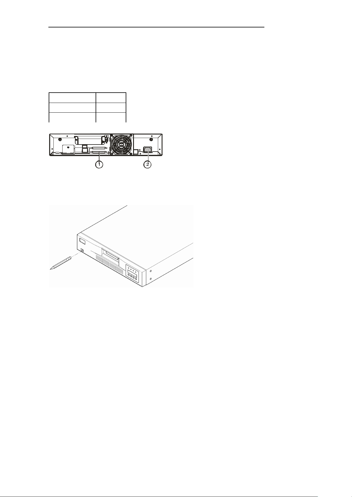
Figure 1 AC line cord, SCSI terminator
1. Install AC line cord, first to autoloader (receptacle 2), then to AC outlet.
2. Install SCSI terminator on autoloader (receptacle 1).
Quick Start Guide
Figure 2 Power switch
3. Use the eraser end of a pencil or something similar to press the left side of the power switch. The
autoloader powers up.
Install data cartridges in slots 1-8:
4. Place cartridge in the cartridge access port.
AUTOLOADER LTO3 – User Reference Manual Rev. 1.01 TANDBERG DATA
Page 12 of 79
Page 13

Figure 3 Operator panel
5. Press any button on the operator panel to change to interaction mode.
6. Choose the "Go Offline" menu and press <Enter>.
7. Choose the "Commands" menu and press <Enter>.
8. Choose "Import", press <Enter>
9. Enter the number of the cartridge slot and press <Enter>.
The cartridge is placed in the chosen slot.
10. Repeat step 4 to 7, until all cartridges are imported.
Drive empty
12345678 SEQ
11. Power up your host computer.
12. Verify your backup software.
Quick Start Guide
AUTOLOADER LTO3 – User Reference Manual Rev. 1.01 TANDBERG DATA
Page 13 of 79
Page 14

Features and Physical Description
Equipment Description
6 Features and Physical Description
6.1 Equipment Description
The autoloader provides automated data storage, archival, backup, and retrieval for a range of
systems, from desktop workstations to small office local area networks.
This chapter describes the autoloader. It includes the following topics:
n Autoloader features
n Component descriptions
n Autoloader accessories
n Related products
Figure 4 Autoloader
AUTOLOADER LTO3 – User Reference Manual Rev. 1.01 TANDBERG DATA
Page 14 of 79
Page 15

Features and Physical Description
Features
6.2 Features
The autoloader includes the following features:
n A carousel encircles the tape drive and positions the specified cartridge slot in front of the tape
drive. A robotic cartridge loader moves the cartridges between the cartridge slots and the tape
drive.
n Storage for up to 8 data cartridges. Cartridges are stored in cartridge slots mounted on the
carousel. One of these cartridge slots can contain a cleaning cartridge.
n A cartridge access port for importing or exporting a single cartridge f rom the autoloader.
n An LCD allows you to monitor autoloader operations, select configuration options, and control the
cartridge loader and carousel from the front panel.
n The autoloader and the tape drive each include independent Small Computer System Interface
(SCSI) controllers. Each supports independent sets of SCSI messages and commands. The
autoloader and the enclosed tape drive use a wide, low -voltage differential (LVD) SCSI interface.
NOTE: Also the LVD SCSI interface is compatible with single-ended (SE) SCSI.
The autoloader is designed as a standalone unit, but can be mounted in a standard 19-inch rack if
desired. Rack mount kits are available from the manufacturer.
Physical characteristics and features
Drive technology IBM LTO Ultrium 3
Total drives 1
Total storage elements 8
Cartridge access port 1
LCD display size and type Two-line x 32 character, ASCII
LCD user interface Four-button keypad
Maximum capacity 3.2 TB native/6.4 TB compressed
Maximum sustained data transfer rate 80 MB/s native/280 MB/s compressed
Table 1 Autoloader features
Parallel SCSI communication interface
Low-voltage differential (LVD) + SE yes
Maximum SCSI bus connections 1
Table 2 SCSI interface
AUTOLOADER LTO3 – User Reference Manual Rev. 1.01 TANDBERG DATA
Page 15 of 79
Page 16
Features and Physical Description
Component Descriptions
6.3 Component Descriptions
The following sections describe the major components of the autoloader.
Front Panel Components
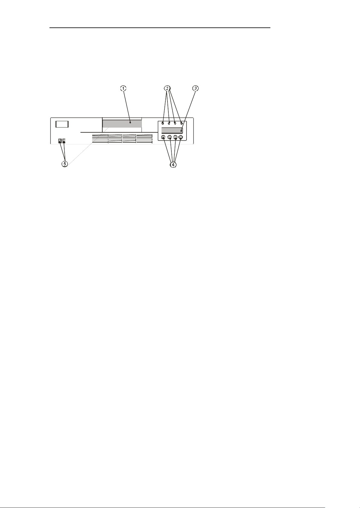
Figure 5 Front panel components
( 1 ) Cartridge access port
The cartridge access port allows you to insert or remove cartridges from the autoloader.
Operator Panel
( 2 ) 4 Status LEDs
( 3 ) Liquid crystal display, 16 characters per line, two lines
( 4 ) Four button keypad
For more information about the operator panel and menu operations, see page 32.
( 5 ) Power switch
The power switch allows you to turn power on and off for the autoloader and the enclosed tape
drive. The switch is recessed into the front panel to prevent the autoloader from being accidently
turned off during operation.
AUTOLOADER LTO3 – User Reference Manual Rev. 1.01 TANDBERG DATA
Page 16 of 79
Page 17
Features and Physical Description
Component Descriptions
Back Panel Components
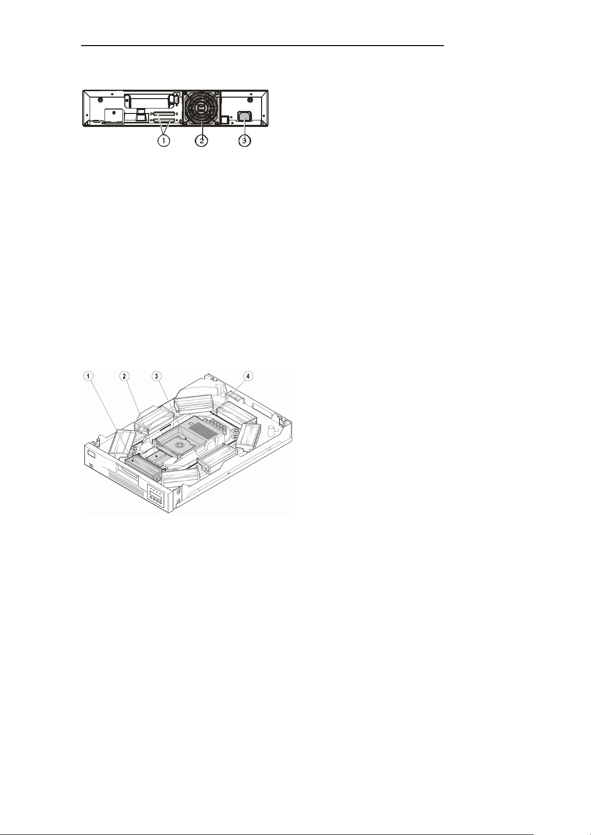
Figure 6 Back panel components
( 1 ) SCSI Connectors
The autoloader has two wide SCSI connectors for connecting the autoloader and tape drive to a
single SCSI bus. The connectors can accommodate either of the following:
– A shielded male, high-density wide (68-pin) SCSI cable
– A wide external terminator
The wide SCSI configuration allows up to 16 devices (including one or more initiators) to be
attached to a single SCSI bus. See SCSI Interface Specification on page 59 for more information
about the SCSI interface.
( 2 ) Fan
The system fan provides cooling for the autoloader and the tape drive.
( 3 ) Power cord connection
The power cord connection provides AC power and chassis grounding to the autoloader and the
tape drive.
Internal Components
Figure 7 Internal components
( 1 ) Cartridge slot
( 2 ) Cartridge loader
( 3 ) Tape drive
( 4 ) Carousel
AUTOLOADER LTO3 – User Reference Manual Rev. 1.01 TANDBERG DATA
Page 17 of 79
Page 18

Features and Physical Description
Component Descriptions
Tape Drive
The autoloader contains one tape drive. The tape drive can sustain a maximum data transfer rate of
280 MB per second (compressed) and can store up to 800 GB of compressed information on a single
data cartridge (assuming an average compression ratio of 2:1).
Cartridge Slots and Carousel
The carousel stores up to eight data cartridges. The carousel consists of a drive chain, guides, and
gears that move the cartridges into position in front of the tape drive. Each cartridge is installed in a
cartridge slot that ensures that the cartridge is properly aligned to be inserted into the tape drive.
If desired, you can use one cartridge slot to hold a cleaning cartridge.
Cartridge Loader
The cartridge loader moves cartridges between the cartridge slots and the tape drive. When a
cartridge slot is positioned in front of the tape drive, the loader grips the sides of the cartridge and
slides it forward or backward between the slot and tape drive. The loader then releases the cartridge
and pushes it firmly into the drive or slot.
Enclosure
The autoloader is housed in a 2 rack-units (ru) high desktop enclosure with a black, textured finish. A
paint kit is available from your vendor for touching up nicks and scratches on the finish.
Autoloader Accessories and Related Pro ducts
The following accessories and products, – available from the manufacturer, are intended for use with
the autoloader:
n 230 V AC power cord
n One Wide SCSI-3 cable
n One LVD Wide SCSI terminator
n Autoloader CD (includes all of the produc t documentation)
n LTO tape data cartridges
n LTO tape Packs
n LTO tape cleaning cartridges
n Rack mount kit
AUTOLOADER LTO3 – User Reference Manual Rev. 1.01 TANDBERG DATA
Page 18 of 79
Page 19

Features and Physical Description
Component Descriptions
Data Cartridges
The tape drive reads and writes to LTO tape data cartridges. The capacity and transfer rates are listed
in 0.
CAUTION
LTO tape
Cartridge type
Ultrium 1 100GB 200GB 580
Ultrium 2 200GB 400GB 580
Ultrium 3 400GB 800GB 680
Table 3 Data cartridge capacities in gigabytes (GB)
1) Assuming a 2:1 compression ratio. Actual compressed capacity varies depending on the type of data being
recorded.
Wrong tapes!
Damages of the tape drive.
Use only LTO tape data cartridges.
Capacity (native) Capacity
(compressed)1)
Tape length (meters)
Gen 3
Native
Capacity
400 GB
(680m)
200 GB
(580 m)
100 GB
(580 m)
50 GB
(290 m)
Table 4 Ultrium Gen3 support
Format Write Read Write Read Write Read
Ultrium 3 yes yes no no no no
Ultrium 2 yes yes yes yes no no
Ultrium 1 yes yes yes yes yes yes
Ultrium 1 yes yes yes yes yes yes
drive
Gen 2
drive
Gen 1
drive
Cleaning Cartridges
Following a regular cleaning schedule for your tape drive will maximize the reliability of your drive and
the life of your LTO tape data cartridges. To clean your tape drive, use only LTO tape Cleaning
Cartridges, available from the manufacturer.
Rack Mount Kit
If you want to mount the autoloader in a rack, you can purchase a rack mount kit from the
manufacturer. The kit includes instructions and all the hardware you need to mount the autoloader in a
standard 19-inch EIA rack. The autoloader occupies 2 rack units.
AUTOLOADER LTO3 – User Reference Manual Rev. 1.01 TANDBERG DATA
Page 19 of 79
Page 20

Installation and Setup
Installing the Optional Remote Management Unit (RMU)
7 Installation and Setup
This chapter describes:
n Installing the Optional Remote Management Unit (RMU)
n Installing the Optional Bar Code Reader (BCR)
n Installing the Autoloader as a Desktop Unit
n Installing the Autoloader in a Rack
n Running Library Verify Test
n Connecting the Autoloader to the Server
7.1 Installing the Optional Remote Management Unit
(RMU)
7.1.1 Contents of the Kit:
n LAN Card.
Formatiert: Nummerierung und
Aufzählungszeichen
7.1.2 Required Tools:
n T10 Torx wrench or small flat-blade screwdriver.
7.1.3 Mounting Instructions:
CAUTION
The LAN card is to be mounted on the rear of the device.
1. Power off the autoloader.
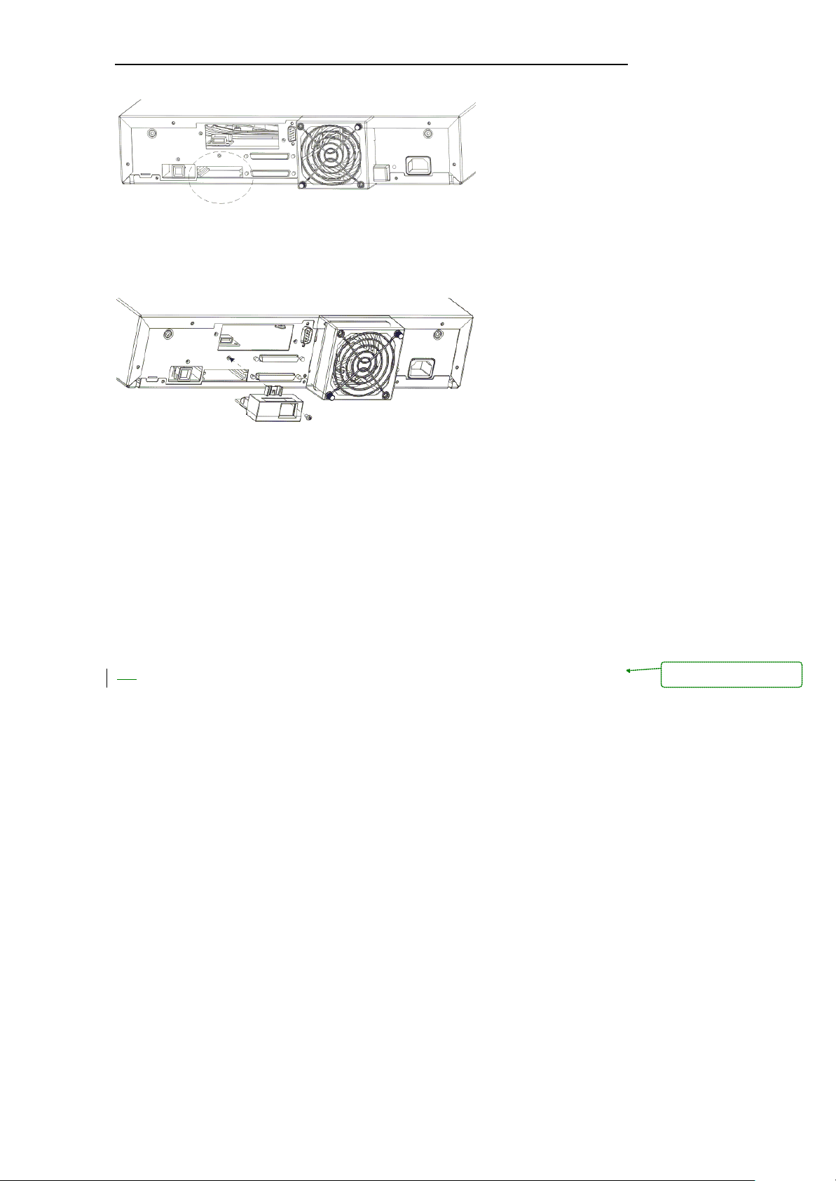
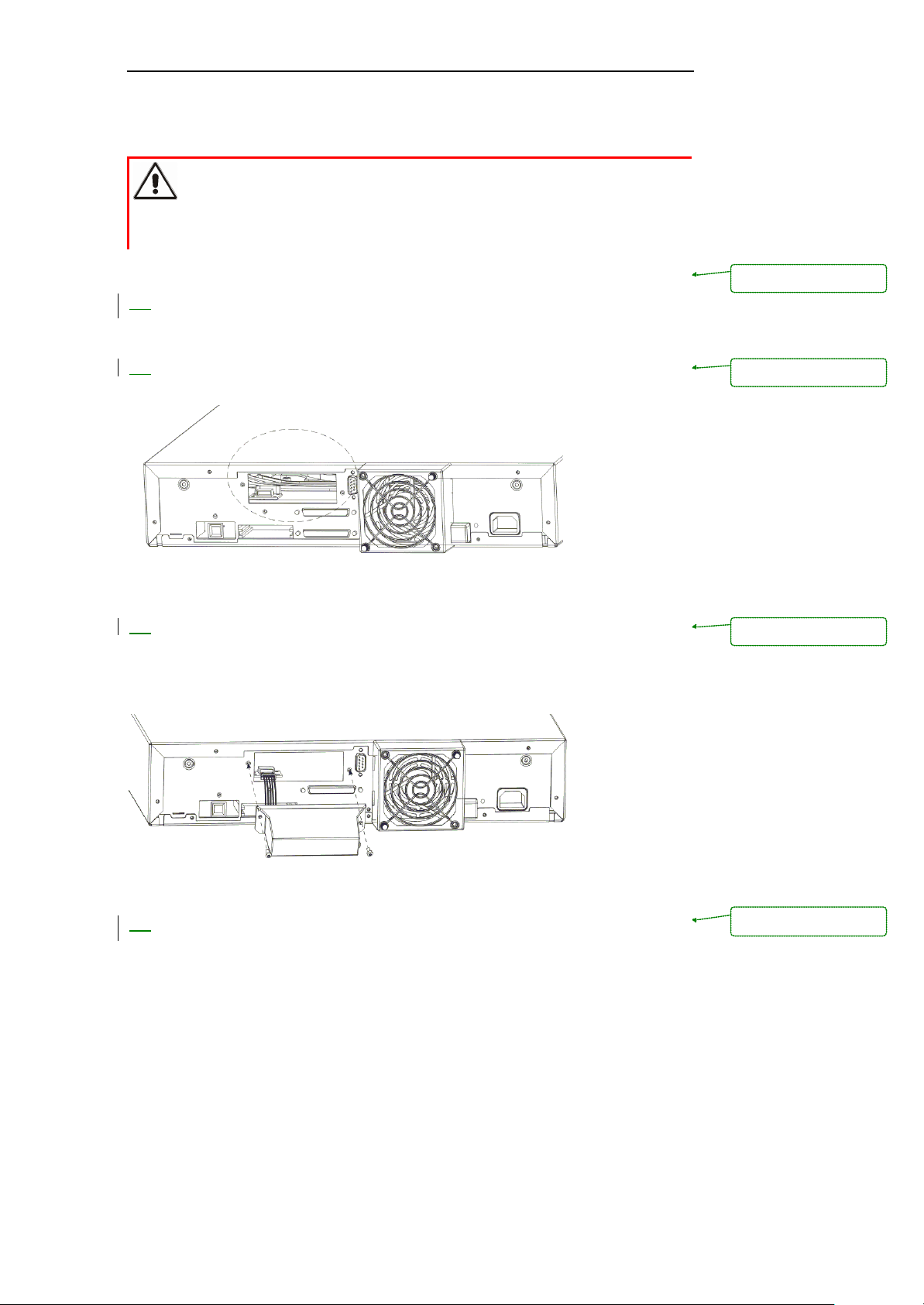
2. Remove the protective covering (located on the autoloader’s rear panel) (see Figure 8 ). Save the
screw.
Electro static discharge!
Destruction of the ESD sensitive components.
Please touch unit cover or rear panel before installing the RMU.
AUTOLOADER LTO3 – User Reference Manual Rev. 1.01 TANDBERG DATA
Page 20 of 79
Page 21
Installing the Optional Bar Code Reader (BCR)
Figure 8 Location of the protective coveri ng for the RMU rail
3. Align the LAN card in the rails and insert into the unit.
4. Fix the unit with the supplied screw (see Figure 9 ).
Figure 9 Positioning of the LAN card
Installation and Setup
5. Attach the Ethernet cable to the RMU and HOST system.
6. Power ON the autoloader and wait for initialization to complete.
7. Configure the RMU via OCP, see ThinStor®Plus LTO3 Autoloader – Operator's Manual.
7.2 Installing the Optional Bar Code Reader (BCR)
7.2.1 Contents of the Kit:
n Barcode reader.
7.2.2 Required Tools:
n Flat-blade screwdriver; small.
Formatiert: Nummerierung und
Aufzählungszeichen
AUTOLOADER LTO3 – User Reference Manual Rev. 1.01 TANDBERG DATA
Page 21 of 79
Page 22
Installation and Setup
Installing the Optional Bar Code Reader (BCR)
7.2.3 Mounting Instructions:
CAUTION
The barcode reader is to be mounted on the rear side of the autoloader.
1. Power down the autoloader.
2. Disconnect the power cord from the outlet. Remove the SCSI cable(s) and power cord from the
rear panel of the autoloader.
3. Remove the cover plate from the rear panel (see Figure 10). Save the screws! Save and store the
cover plate; you may use this plate later after removing the barcode reader.
Electro static discharge!
Destruction of the ESD sensitive components.
Please touch unit cover or rear panel before installing the RMU.
Formatiert: Nummerierung und
Aufzählungszeichen
Formatiert: Nummerierung und
Aufzählungszeichen
Figure 10 Location of the cover plate for the BCR rail
4. Orient the barcode reader before the slot. There is only one correct orientation. Check whether the
holes align.
5. Connect the cable to the barcode controller outlet.
6. Attach the barcode reader with the screws (see Figure 11).
Figure 11 Connecting of the BCR
7. Reconnect the SCSI cables and power cord to the autoloader.
8. Power on the autoloader.
AUTOLOADER LTO3 – User Reference Manual Rev. 1.01 TANDBERG DATA
Page 22 of 79
Formatiert: Nummerierung und
Aufzählungszeichen
Formatiert: Nummerierung und
Aufzählungszeichen
Page 23

Installation and Setup
Installing the Optional Bar Code Reader (BCR)
7.2.4 Configuration of the Barcode Reader
1. Enable Barcode Reader through the Operator Panel. Select menu item
CONFIGURATION/BARCODE READER and set BCR CHANGE TO „ON”.
2. The barcode reader is controlled through the host software.
3. The autoloader and host system will sense the presence of the barcode reader.
7.2.5 Barcode Labels
The barcode reader can only operate, if barcode labels are present on the tape cartridges. Please
make sure that only barcode labels according to the appropriate barcode label specification are used!
7.2.6 Removing the Barcode Reader
1. Disable Barcode Reader through the Operator Panel. Select menu item
CONFIGURATION/BARCODE READER and set BCR CHANGE TO "OFF"
2. Power down the autoloader.
3. Disconnect the power cable from the outlet. Remove the SCSI cable(s) and power cable from the
rear panel.
4. Unscrew the screws that fix the barcode reader to the rear panel.
5. Unplug the barcode reader connector from the controller outlet.
6. Replace the cover panel on the rear panel.
Formatiert: Nummerierung und
Aufzählungszeichen
AUTOLOADER LTO3 – User Reference Manual Rev. 1.01 TANDBERG DATA
Page 23 of 79
Page 24

Installation and Setup
Installing the Autoloader as a Desktop Unit
7.3 Installing the Autoloader as a Desktop Unit
WARNING
7.3.1 Checks Before Installation:
If you install the autoloader as a desktop unit, position the autoloader in a location that is away from
dust, dirt, and debris, and is convenient to the server (host) to which it will be attached. The only
restrictions are the length of the power cord and the length of the SCSI cable.
For a desktop installation, position the autoloader in the following recommended locations:
n Away from high-traffic areas, especially if the floor is carpeted.
n Out of copy rooms to avoid toner and paper dust. Do not store paper supplies near any unit.
n Away from moving air, such as doorways, open windows, fans, and air conditioners.
n Off the floor.
n In a horizontal position on a flat surface.
n Where a tape cartridge can be easily inserted into the I/O Door.
Weights on the autoloader!
Destruction of the autoloader's chassis.
The autoloader should not be stacked. Do not place anything on top of
the autoloader.
7.3.2 Connecting Power
1. Plug the power cord into the receptacle at the rear of the autoloader
2. Plug the other end of the power cord into a grounded electrical outlet.
3. Power on the autoloader.
The autoloader will verify the drive configuration and status, build a valid cartridge inventory log , and
calibrate the robotic cartridge loader.
The OCP’s green READY/ACTIVITY LED (light -emitting diode) will blink during this initialization
process.
When the autoloader completes the Power-On Self Test (POST) for the drive and the library, the
green READY/ACTIVITY LED will stop blinking.
The autoloader will be in automatic mode (the default mode) and SEQ will appear in the lower right
corner of the OCP display.
For information about the autoloader’s modes of operation, see ThinStor®Plus LTO3 Autoloader –
Operator's Manual. If a failure occurred, the red ERROR LED will light up and an error message will
be displayed on the OCP. See Troubleshooting and Diagnostics on page 40.
4. If the power on is successful, run the Library Verify test (see Running Library Verify Test on
page 28).
AUTOLOADER LTO3 – User Reference Manual Rev. 1.01 TANDBERG DATA
Page 24 of 79
Page 25

Installation and Setup
4.45cm
(1.75in.)
(1.75in.)
Installing the Autoloader in a Rack
7.4 Installing the Autoloader in a Rack
You have to install the autoloader into a standard 19-inch rack.
Required Tools:
n Phillips screwdriver, size 2
n Torx wrench, T10 (part of kit)
7.4.1 Prepare the Autoloader for Installation
CAUTION
If the Autoloader is already in operation as a standalone unit, prepare it for Installation in the rack as
follows:
1. Power off the Autoloader using the POWER button on the front panel.
2. Remove the power cord and any cables or terminator attached to the Autoloader. Note the
configuration of the cables and terminator for reconnecting them after installing the Autoloader in
the rack.
Disrupting communication between the server (host) and other
devices on the SCSI bus!
Incomplete data storage.
Make sure there is no SCSI activity on the bus before you power of the
autoloader.
7.4.2 Install the Support Rails in the Rack
1. Remove the two support rails from the kit and note how they will be positioned in the rack. When
the rails are properly installed, the shelf flanges will face inward to support the autoloader.
NOTE: The autoloader requires 2 EIAs of rack space for installation.
2. Identify the 2 EIAs required by the autoloader for rail placement.
4.45cm
Figure 12 EIA identification
AUTOLOADER LTO3 – User Reference Manual Rev. 1.01 TANDBERG DATA
Page 25 of 79
Page 26

Installation and Setup
Installing the Autoloader in a Rack
3. Install the cage clip-nuts (for racks with square mounting holes) from the back side of each rail.
Figure 13 Attaching cage cilp nuts to a rack with square holes
NOTE: To ensure proper installation of the Autoloader in your rack, it is very important to install the
clip-nuts in the correct positions on each rail.
4. Count the holes on the other three rack rails, up or down, to determine the position of the top or
bottom clip-nut.
5. From the front of the rack, position one of the rails on the appropriate side.
6. Position the front flange so that it is on the outside of the strip of mounting holes in the rack (see
Figure 14).
Figure 14 Attaching expanding rails to the rack
7. Using a #2 Phillips screwdriver, attach the rail to the rack with screws and washers from the kit.
8. Slide the rail pieces apart to match the depth of your rack.
9. Using a #2 Phillips screwdriver, attach the rail to the outside of the rack with screws and washers
supplied with the rack mount kit.
10. Repeat steps 5 through 9 to install the second rail.
AUTOLOADER LTO3 – User Reference Manual Rev. 1.01 TANDBERG DATA
Page 26 of 79
Page 27

Installation and Setup
Installing the Autoloader in a Rack
7.4.3 Install the Rack Front Mount Brackets on the Autoloader
1. Determine on which side of the autoloader the rack mount brackets will be attached (see
Figure 15). The oval hole for attaching the bracket to the rack will be on the bottom of the arm of
the bracket.
Figure 15 Mounting position of rack mount bracket, left side
2. Using the Torx wrench, Remove the two screws on each side of the autoloader cover.
3. Position the correct bracket, as determined in Step 1, on each side of the autoloader and secure
by reusing the original screws (see Figure 15).
7.4.4 Secure the Autoloader to the Rack
1. From the front of the rack, position the autoloader on the shelf flanges between the support rails.
Slide it toward the rear of the rack un til the brackets contact the rack’s mounting holes.
NOTE: Make sure that the tabs on the back of each shelf flange are fully engaged in the slots at the
Figure 16 Installing the Autoloader in a rack
2. Place one screw and washer from the rack mount kit into the hole in the front of each bracket.
rear of the autoloader.
Take care that the screws line up with the holes containing the remaining installed clip-nuts. Use a
#2 Phillips screwdriver to tighten the screws.
AUTOLOADER LTO3 – User Reference Manual Rev. 1.01 TANDBERG DATA
Page 27 of 79
Page 28

Installation and Setup
Running Library Verify Test
7.4.5 Connecting Power
1. Connect the PCC cable (included with your rack mount kit) to the rear of the autoloader.
2. Connect the other end of the PCC cable to your rack’s power strip.
3. Power on the power strip.
4. Power on the autoloader.
The autoloader will verify the drive configuration and status, build a valid cartridge inventory log, and
calibrate the robotic cartridge loader.
The OCP’s green READY/ACTIVITY LED (light -emitting diode) will blink during this initialization
process.
When the autoloader completes the Power-On Self Test (POST) for the drive and the library, the
green READY/ACTIVITY LED will stop blinking.
The autoloader will be in automatic mode (the default mode) and SEQ will appear in the lower right
corner of the OCP display.
For information about the autoloader’s modes of operation, see ThinStor®Plus LTO3 Autoloader –
Operator's Manual. If a failure occurred, the red ERROR LED will light up and an error message will
be displayed on the OCP. See Troubleshooting and Diagnostics on page 40.
5. If the power on is successful, run the Library Verify test (see Running Library Verify Test on
page 28).
7.5 Running Library Verify Test
1. Press Enter on the OCP at the ONLINE screen.
2. Press Next four times to navigate to the Diagnostic Menu.
3. Press Enter to navigate to the LOADER DIAG menu item.
4. Press Enter to access LIBRARY VERIFY.
5. Press Enter to begin the verification.
6. On the OCP display, you will be asked to insert a cartridge.
7. When the I/O Door opens, insert a blank cartridge or a scratch cartridge.
The I/O Door will close automatically.
While the test is running, the OCP will display library status.
8. If the test PASSED, proceed to the next step.
9. If the test FAILED, see Determining a Problem on page 41.
10. Press Enter.
11. When prompted by the OCP display, remove the cartridge.
12. Press Enter to end the test.
13. Power off the autoloader.
AUTOLOADER LTO3 – User Reference Manual Rev. 1.01 TANDBERG DATA
Page 28 of 79
Page 29

Installation and Setup
Connecting the Autoloader to the Server
7.6 Connecting the Autoloader to the Server
The autoloader has to be attached to a SCSI/LVD system.
Cabling is required for the tape drive interface and the RMU, if installed, in order for your server (host)
to communicate with the autoloader. The following sections include information on options cabling and
drive interface connections.
7.6.1 Connecting to RMU
NOTE: If you are plugging the RMU directly into a PC, use a special crossover Ethernet cable (not
1. Plug an Ethernet cable into the RMU mounted on the rear of the autoloader.
2. Plug the other end of the Ethernet cable into your network switch or hub.
7.6.2 Connecting to SCSI bus
A SCSI cable is required for each server connection to a SCSI bus. An LVD SCSI terminator may be
included in your ship group.
!
!
Connecting to a SCSI-LVD System
1. Plug the SCSI cable into the top SCSI receptacle (1) on the rear panel of your autoloader.
Figure 17 SCSI receptacles
supplied).
IMPORTANT
Be sure to install the appropriate SCSI host bus adapter and software on your
server (host). For more information, see your server (host) documentation and
application software.
2. Plug the LVD SCSI terminator (or another SCSI cable connecting to another SCSI device) into the
bottom SCSI receptacle (2) on the rear panel of your autoloader.
3. Connect the SCSI cable to your server (host).
AUTOLOADER LTO3 – User Reference Manual Rev. 1.01 TANDBERG DATA
Page 29 of 79
Page 30

Operation and Maintenance
General Guidelines
8 Operation and Maintenance
This chapter describes the requirements for using the autoloader, including information about:
n General Guidelines
n Powering on the System
n Powering on the System
n Using the Operator Panel and Menu Options
n Operational Modes
n Configuration
n Operation
n Performing Autoloader and Tape Drive
n Shipping
8.1 General Guidelines
Do not open the front door of the autoloader unless you must perform interaction mode commands, or
change media.
Use only the recommended types of media cartridges.
Clean the drive whenever necessary.
CAUTION
Disrupting data storage!
Incomplete data storage.
Never insert or remove cartridges from the cartridge slot unless
READY/ACTIVITY is lit.
8.2 Powering on the System
Switch on power at the POWER button located on the front panel, after the power cord and the SCSI
cabel are connected. The autoloader will power up.
If an RMU is installed, look on the rear panel of the autoloader and verify that the RMU’s green LED is
on. If the green LED is not on, check the connection to the RMU, see Installing the Optional Remote
Management Unit (RMU) on page 20. Otherwise call the Technical Support.
When the autoloader powers up, or resets, it goes through several internally controlled processes that
allows it to get initialized and running. While those processes are happening, the operator panel shall
have appropriate information displayed to keep the user informed. When the autoloader finishes
coming alive, it will display the Current Drive mount status in the ‘Home Screen’. It also indicates that
sequential mode is ON by posting the SEQ string.
If the drive is empty, the following status will be displayed:
Drive empty
12345-78 SEQ
AUTOLOADER LTO3 – User Reference Manual Rev. 1.01 TANDBERG DATA
Page 30 of 79
Page 31

Operation and Maintenance
Powering on the System
If the autoloader detects that a cartridge is loaded when it first comes alive, the following status will be
displayed on the operator panel:
Drive loaded
12345-78 SEQ
In this example, there is no cartridge in slot 6. Inventory status will be displayed as an 8-character
string, with 4 blank spaces on each side.
Inventory status characters
Current Drive Status/Activity Drive loaded
Inventory Status
The inventory status characters will be represented as follows:
Character Meaning
1 … 8 Slot Full – uses the slot numbers 1 to 8
– Slot Empty – a dash is displayed as place holder
1/(0xff) A cartridge that is being loaded, unloaded, imported, exported, or is loaded
in the drive, will be represented by the slot number alternating with the block
(0xff) character. The alternating rate should be approximately 1-second per
cycle, 50% duty cycle.
12!45-78 SEQ
! A cartridge that has been identified as faulty (and Media Attention LED is on)
Table 5 Inventory Status characters
will be repre sented by an exclamation point. An invalid cartridge will be
identified the same way.
LEDs
Figure 18 LEDs
AUTOLOADER LTO3 – User Reference Manual Rev. 1.01 TANDBERG DATA
Page 31 of 79
Page 32

Operation and Maintenance
Using the Operator Panel and Menu Options
The 4 LEDs (1 -4) are updated during power up and reset sequences. Upon power up or software
reset, the autoloader will illuminate all LEDs as soon as power on self-test (POST) allows. This will
help the user to verify if all LEDs are functional.
When mechanical initialization starts, all LEDs will be extinguished and the READY/ACTIVITY LED (1)
will flash at a reasonable rate of approximately 1-second per cycle, 50% duty cycle.
When the mechanical initialization is complete, the READY/ACTIVITY LED (1) will stop flashing and
be constantly illuminated.
If an autoloader failure occurs, the READY/ACTIVITY LED (1) will be turned off and the error LED (4)
will be illuminated. The operation panel will also display an appropriate error code to help identify the
failure.
8.3 Using the Operator Panel and Menu Options
Figure 19 Operator panel
( 1 ) READY/ACTIVITY, Green LED
It is lit any time the unit is powered on and able to function. It should blink whenever there is
autoloader or drive activity.
( 2 ) CLEAN DRIVE, Amber LED
It will be lit when the drive is to be cleaned. The LED will be turned off after the drive is cleaned
successfully.
( 3 ) MEDIA ATTENTION, Amber LED
It will be lit when there has been a failure that indicates that there is a piece of media that is bad,
marginal or invalid. It will be cleared when all invalid cartridges have been exported from the
autoloader.
( 4 ) ERROR, Red LED
It should be lit when there is an unrecoverable autoloader or drive failure. A message is
displayed at the same time on the screen. It will be cleared when the error state is resolved.
( 5 ) CD display, consisting of two lines with 16 characters per line
The screen displays actions and status information, menu items or error messages equivalent to
the operation mode.
AUTOLOADER LTO3 – User Reference Manual Rev. 1.01 TANDBERG DATA
Page 32 of 79
Page 33

Operation and Maintenance
Operational Modes
( 6 ) ENTER, button [↵]
It is used in interaction mode. Push the enter button to go to a sub menu or to force a robotic
action.
( 7 ) NEXT, button [+]
It is used in interaction mode to navigate through menu items.
( 8 ) PREVIOUS, button [–]
It is used in interaction mode to navigate through menu items.
( 9 ) CANCEL, button [X]
It is used in interaction mode. Push the CANCEL button to cancel a user action and return to the
last menu item.
8.4 Operational Modes
The operational modes affect how the autoloader loads cartridges into the drive. The different modes
can be selected at the configuration menu in the OCP. They are stored persistent in the NVRAM and
are valid also after Power ON.
There are 2 basic modes that the OCP operates in. First is the User Interaction mode. This mode is
employed when a user is pushing buttons on the OCP (Operator Control Panel). The second mode is
the System Driven mode. This is the normal mode of operation. In this mode, the OCP displays status
associated with the actions that were caused from commands issued via the Drive’s serial interface.
Actions like loading, rewinding or moving tape will be displayed. When an OCP button is pressed and
released, the OCP automatically transitions to User Interaction mode. User Interaction mode will
continue until 3 minutes after a user stops pushing buttons, or the requested robotic action stops;
whichever is longer. At this time the OCP will return to System Driven mode.
If necessary, the OCP will automatically transition to the System Driven mode. When this occurs, the
LTO3 Autoloader must remember what the User was doing before the display mode changed.
Therefore the next button pressed will only transition the OCP to the User Interaction mode from the
System Driven mode.
In case of activated User security feature the User Interaction Mode is restricted to the Information and
Login menu item, until a login with correct PIN is done.
For User Interaction mode display information and rules see ThinStor®Plus LTO3 Autoloader –
Operator's Manual.
8.4.1 Automatic Mode
Automatic Mode is the default setting and allows the autoloader to switch between Random and
Sequential Mode depending on the SCSI command received. In this mode Sequential Mode is
activated after Power On.
Every MOVE MEDIUM, READ ELEMENT STATUS or INITIALIZE ELEMENT STATUS command
disables Sequential Mode and activates Random Mode. The unit will switch back to Sequential Mode
with every OCP initiated Load Command.
8.4.2 Random Mode
In Random Mode the Media Exchanger SCSI target is visible on the SCSI bus, i.e. the autoloader
allows the host application software to select any cartridge in any order. Cartridges can be moved by
MOVE MEDIUM commands in random order. Unload commands to the drive should not be executed.
AUTOLOADER LTO3 – User Reference Manual Rev. 1.01 TANDBERG DATA
Page 33 of 79
Page 34

Operation and Maintenance
Operational Modes
8.4.3 Sequential Mode
In Sequential Mode the Media Exchanger is no longer visible on t he SCSI bus. Cartridge
replacements are initiated by an ‘Unload’ command sent to the drive.
Sequential Mode presumes that the first cartridge was previously loaded to the drive, i.e. the operator
determines the first cartridge to load by loading the desired cartridge into the drive using the ‘Load
Cartridge’ menu item on the OCP. When the first tape is unloaded with a drive ‘Unload’ command, the
autoloader removes the cartridge from the drive and puts it in its original slot. After that, the next
cartridge in order will be moved into the drive. This queue stops if the last cartridge has been ejected
und unloaded to the slot.
NOTE: If Sequential Mode is activated (menu item CONFIGURATION/CHANGE LDR
MODE/TO:SEQUENTIAL), the media exchanger is not logically connected the SCSI bus
and does not respond to SCSI commands. Every SCSI command (except INQUIRY and
REQUEST SENSE) sent to the media exchanger is rejected with a Check Condition (sense
key 02/04/8E). For further details please see the Media Exchanger SCSI Command
Specification.
In Sequential Mode the display shows the following screen where the string ‘SEQ’ indicates that
Sequential Mode is activated:
Drive empty
12345-78 SEQ
To further determine how you want cartridges loaded into the drive while in Sequential Mode, you can
set Loop Mode and Autoload Mode from the OCP.
8.4.4 Loop Mode
Loop Mode is a special type of Sequential Mode. The cartridges exchange queue will not terminate
with the last cartridge but restart with the first cartridge. This mode allows endless backup operation
without user interaction.
8.4.5 Autoload Mode
This is also an option of Sequential Mode and could be combined with Loop Mode. The first cartridge
will be loaded automatically if the unit powers up with an empty drive. In this case user interaction via
OCP is not required.
AUTOLOADER LTO3 – User Reference Manual Rev. 1.01 TANDBERG DATA
Page 34 of 79
Page 35

Operation and Maintenance
Operational Modes
8.4.6 Menu Structure and Options OCP User Interaction Mode
ANY
KEY
INFORMATION
(INV. STATUS)
CANCEL
ENTER
LOADER INFO.
(INV. STATUS)
DRIVE INFO.
(INV. STATUS)
(-)
(+)
(-)
(-)
(-)
(+)
CANCEL
IMPORT
(INV. STATUS)
EXPORT
(INV. STATUS)
LOAD
CARTRIDGE
(INV. STATUS)
UNLOAD
CARTRIDGE
(INV. STATUS)
CLEAN DRIVE
(INV. STATUS)
RE-INVENTORY
(INV. STATUS)
COMMANDS
(INV. STATUS)
ENTER
BULK EXCHANGE
(INV. STATUS)
(+)
NOTES:
1. CANCEL, from any LCD display in
row, will return to Curent Status, Home
Screen.
2. CANCEL, from all lower LCD displays,will
return to the Respective LCD display, detailed
in the top ROW.
3. ENTER, from all lower LCD displays
will invoke operation depicted on LCD.
Figure 20 Interaction Mode, overview
(+)
(-)
CONFIGURATION
(INV. STATUS)
CANCEL
ENTER
(-)
RESET
(INV. STATUS)
(-)
(+)
CHANGE SCSI ID
(Inv. Status)
(-)
(+)
HI SPEED SCSI
MAX SPEED
(-)
(+)
DRIVE FW
UPGRADE
FROM FMR TAPE
(-)
(+)
CHANGE LDR
MODE
AUTOMATIC
(-)
(+)
LOOP MODE
OFF
(-)
(+)
AUTOLOAD MODE
OFF
NET PARAMETER
(INV. STATUS)
BARCODE
READER
OFF
PROTECTION
MODE
OFF
SERIAL NUMBER
0123456789
(+)
(+)
(+)
(+)
(-)
(+)
(+)
(-)
(-)
(+)
(+)
(+)
(+)
(+)
(-)
(-)
(-)
(-)
(+)
(-)
(-)
(-)
(-)
DIAGNOSTIC
(INV. STATUS)
CANCEL
ENTER
LOADER DIAG.
(INV. STATUS)
DRIVE DIAG.
(INV. STATUS)
(+)
(-)
(INV. STATUS)
GO ONLINE
ARE YOU SURE ?
(-)
(+)
GO ONLINE
CANCEL
ENTER
ENTER
Drive Empty
(INV. STATUS)
See Note 2 & 3
AUTOLOADER LTO3 – User Reference Manual Rev. 1.01 TANDBERG DATA
Page 35 of 79
Page 36

Operation and Maintenance
Configuration
8.5 Configuration
For most installations, the default configuration of the autoloader does not need to be changed. For
further information see ThinStor®Plus LTO3 Autoloader – Operator's Manual. However, if necessary,
you can use the operator panel to make the following changes to the autoloader configuration:
You can change the SCSI IDs for the autoloader and the tape drive using the 'Configuration'.
IMPORTANT
!
!
The autoloader and the tape drive must each have unique SCSI IDs. It is your
responsibility to make sure you do not assign duplicate IDs within a bus.
8.6 Operation
After you install and configure the autoloader and install your application software on the host
computer, the autoloader performs most operations automatically. Operator intervention includes the
following activities:
n Monitoring autoloader operation and status
n Performing autoloader and tape drive operations
8.6.1 Monitoring Autoloader Operation and Status
During normal operation, the 'Status screen' is displayed on the LCD. You can use this screen to
monitor autoloader activities. By default, the 'Status screen displays the current operating status of the
autoloader and tape drive.'
To set the operator panel to user interaction mode, press a key. This mode allows you to use the
[Enter] or [Cancel] and [+] or [–] buttons to display options for issuing commands to the autoloader,
viewing information screens, and configuring the autoloader.
8.7 Performing Autoloader and Tape Drive
The 'Commands' screen provides options for importing and exporting cartridges, loading and
unloading a cartridge from the tape drive, cleaning the tape drive, and updating the cartridge
inventory.
8.7.1 Importing and Exporting Cartridges
The Import command under the Library Commands menu allows you to place a cartridge into a
specific cartridge slot through the cartridge access port.
When you issue an Import command, the cartridge carousel moves the specified cartridge slot into
position in front of the cartridge access port and slides the door open. You can then push the cartridge
into the slot through the door. The cartridge loader then grasps the cartridge, pulls it into the
autoloader, and closes the door.
The 'Export' command allows you to remove a cartridge from a specific cartridge slot through the
cartridge access port. When you issue an 'Export' command, the cartridge carousel moves the
specified cartridge slot into position in front of the cartridge access port and slides the door open. The
cartridge loader then pushes the cartridge far enough out through the door to allow you to remove it.
AUTOLOADER LTO3 – User Reference Manual Rev. 1.01 TANDBERG DATA
Page 36 of 79
Page 37

Operation and Maintenance
Performing Autoloader and Tape Drive
8.7.2 Bulk Exchange
The menu item Bulk Exchange was designed to make the autoloader more user friendly. This item
enables a user to import or export a specific amount of cartridges e.g. this item makes sense if a user
wants to exchange a complete set of cartridges. Bulk Exchange operation starts with slot #1. If a
cartridge is available this cartridge will be exported. It’s up to the user to import a new cartridge or to
move to the next slot #2. The same procedure then takes place for slot #2 to slot #8.
8.7.3 Load and unload a Cartridge
The load cartridge command under the 'Commands' menu allows you to load the cartridge in the
specified slot into the tape drive. When you issue a 'Load cartridge' command, the cartridge carousel
moves the specified cartridge slot into position in front of the tape drive. The cartridge loader then
extracts the cartridge from the cartridge slot and inserts it into the tape drive.
The 'Unload cartridge' command causes the tape drive to unload the tape from the tape path and eject
the cartridge. After the cartridge is ejected, the cartridge carousel moves the slot from which the
cartridge originated into position in front of the tape drive. The cartridge loader then extracts the
cartridge from the tape drive and returns it to the cartridge slot.
8.7.4 Write Protected Media
If the drive detects a write protected media, an internal bit is set and the autoloader posts the “WP”
string on the display indicating a write protected media is loaded in the drive.
The display shows the following status:
Drive loaded
12345-78 WP
As soon as the write protected media is ejected, the drive resets the internal bit and the “WP” string on
the display is cancelled.
8.7.5 Cleaning the Tape Drive
The tape drive contains an automatic cleaning mechanism that allows it to clean itself as necessary. In
addition, the tape drive requires regular cleaning with a LTO tape cleaning cartridge to maintain
optimal performance.
To clean the tape drive, use LTO tape cleaning cartridges only.
CAUTION
AUTOLOADER LTO3 – User Reference Manual Rev. 1.01 TANDBERG DATA
Page 37 of 79
Wrong cleaning cartridge!
Damages of the tape drive and loosing warranty.
Use only LTO tape cleaning cartridges. Using other types of cleaning
cartridges will void your warranty.
Carefully follow all instructions and recommendations provided with the
cleaning cartridge.
Page 38

Operation and Maintenance
Performing Autoloader and Tape Drive
NOTE: The tape drive can also report its cleaning requirements to the application software. Your
application may notify you when the tape drive needs cleaning. See your application
documentation for more information.
To clean the tape drive, select the 'Clean drive' option from 'Commands' menu on the operator panel.
When you use this option, the autoloader imports a cleaning cartridge through the cartridge access
port and inserts it into the tape drive.
When the cleaning is complete, the tape drive ejects the cleaning cartridge and the autoloader returns
it to the cartridge a ccess port for removal.
Alternatively, you can store a cleaning cartridge in one of the cartridge slots. You use the 'Load' option
from the 'Commands' menu to move the slot containing the cleaning cartridge into position and load
the cartridge into the tape drive. When the cleaning is complete, the tape drive ejects the cleaning
cartridge and the autoloader returns it to the slot from which it originated. Although this alternative
allows you to always have the cleaning cartridge in the autoloader, it has following disadvantages:
n You have to remember which slot your cleaning cartridge is in.
n The autoloader's data-storage capacity is reduced by one cartridge.
n Some software applications may not support reserving a slot for a cleaning cartridge.
Your backup software might offer additional possibilities for cleaning the tape drive. For details please
see the relevant section of the corresponding documentation.
Updating the Cartridge Inventory
After you import or export a data cartridge, you can update the cartridge inventory using the 'Re inventory' option under the 'Commands' menu. The autoloader checks for the presence of a cartridge
in each cartridge slot.
Resetting the Autoloader
A reset causes the autoloader to perform its power-on self-test (POST) and check for the presence of
the data cartridges. The autoloader can be reset in any of the following ways:
n Power-on reset. Powering the autoloader off (or unplugging it), then back on again resets the
autoloader and the tape drive.
n Bus device reset message. Issuing a bus device reset message from the SCSI application
program can reset either the autoloader or the tape drive.
n SCSI bus reset. A RST (reset) pulse occurring on the SCSI bus for a minimum of 25 µs causes
the autoloader and tape drive to be reset. A SCSI bus reset immediately clears all devices on the
bus, resets their associated equipment, and terminates all pending I/O processes.
Resetting the tape drive does not cause a cartridge loaded in the drive to be ejected. If a cartridge is in
the tape drive during a reset, make sure that it is safe to overwrite the loaded cartridge before
performing a backup. If you perform a backup without checking the loaded cartridge, you may lose
important data from a previous backup.
AUTOLOADER LTO3 – User Reference Manual Rev. 1.01 TANDBERG DATA
Page 38 of 79
Page 39

Operation and Maintenance
Shipping
Performing Routine Maintenance and Service
The autoloader requires no routine maintenance. If necessary, you can use touch-up paint on the
housing. Touch-up paint is available for covering nicks and scratches on the f inish. Contact your
vendor to order touch-up paint. All other parts can be serviced only by the manufacturer, an approved
maintenance organization, or by self-maintenance contract customers.
CAUTION
IMPORTANT
!
!
Cleaning solvents or lubricants!
Malfunction of mechanical assemblies.
Do not clean or lubricate any of the autoloaders mechanical assemblies.
All parts have to be serviced only by the manufacturer, an approved
maintenance organization, or by self-maintenance contract customers.
The autoloaders warranty does not apply to failures of the autoloader when it is
repaired by untrained or unauthorized service personnel.
8.8 Shipping
If you need to ship the autoloader, use the original shipping carton and packing materials (or
replacement packaging obtained from the vendor) to prevent damage. The shipping carton and
packing materials are not intended to be used for shipping items other than or in addition to the
autoloader.
AUTOLOADER LTO3 – User Reference Manual Rev. 1.01 TANDBERG DATA
Page 39 of 79
Page 40

Troubleshooting and Diagnostics
General Guidelines
9 Troubleshooting and Diagnostics
9.1 General Guidelines
The autoloader includes features to support troubleshooting and diagnostic operations.
If an autoloader error occurs, the red error LED is on, an error message and error code are displayed
on the Status Screen.
Additionally, the autoloaders internal 'TapeAlert' firmware constantly monitors the autoloaders
operation for problems. 'TapeAlert' is an industry-standardized method for reporting errors and
potential difficulties to the software application.
To check if the autoloader is operational the system offers a system test. It is accessible via the item
“Diagnostic” in the system menu. See ThinStor®Plus LTO3 Autoloader – Operator's Manual.
Preconditions:
n tape drive empty
n at least one slot contains a cartridge
n no drive may contain a cleaning cartridge
Mode of operation:
Depending on the firmware revision either you are asked to select the number of cycles or only an
endless test is offered. During the test in an arbitrary sequence cartridges are moved, mounted and
dismounted. Thus most of the autoloader’s functions are tested. The test can be stopped anytime by
pressing the “Cancel” button.
9.2 Reacting on Lightening Error LED/Error Code
1. If the red error LED is on and an error message and error code are displayed on the Status
Screen note the code or information.
2. Press Enter to attempt recover and initialization. Cycling power may also be necessary.
3. If possible, running the Library Verify test in the Diagnostic Menu (see ThinStor®Plus LTO3
Autoloader – Operator's Manual).
NOTE: If the Media Attention LED turns on red, this is an indication that a drive error occurred
AUTOLOADER LTO3 – User Reference Manual Rev. 1.01 TANDBERG DATA
Page 40 of 79
pointing to the me dia as the possible problem. For instance, if during the Library Verify
diagnostic, the drive read/write test fails with a media error, the Media Attention LED
becomes active thus ending the test. To determine the drive error code after the cartridge is
unloaded and returned to the I/O Door for removal, perform one of the following procedures
to determine the latest drive error code.
Page 41

Troubleshooting and Diagnostics
Determining a Problem
9.2.1 Viewing Drive Error Codes via the OCP
1. From the OCP, press Enter to access the Information Menu.
2. Press Next to access DRIVE INFO.
3. Press Next or Previous until ERROR LOG appears.
4. Press Enter to display the most recent error code.
5. Line one will indicate ERROR CODE 0; line two will show a single hex digit drive error code (see
Drive Error Code Descriptions on page 55).
6. Press Previous to view previous error codes (up to ten error codes are stored).
9.2.2 Viewing Drive Error Codes via Serial Communication
1. From the TSMON> prompt, login (lgi) as ?admin? (Administrator needs appropriate password).
2. From the TSMON> prompt, type drv1 (display drive error log).
The entire drive error log table will display (up to ten errors if ten are available).
The first byte in the string of five bytes will contain the drive error code. The drive error code is
displayed in ASCII. For example, if the single hex drive error code is a ?7? (media error), the
representation displayed in the drive error log table will show a ?37?. the remaining four bytes on each
line are development information and can be ignored. The most recent drive error code is on line one.
9.2.3 Viewing Drive Error Codes via the RMU
1. Login as Administrator.
2. Click on Logs and then Drive.
The drive error log table described for serial communication is displayed.
9.3 Determining a Problem
1. Check if the autoloader powers on?
YES:
n Proceed with step 2.
NO:
n Check if power cord is plugged in at autoloader and at the electrical outlet.
n Try another electrical outlet or plug another device into outlet to test.
n Try another power cord.
n Replace the autoloader
AUTOLOADER LTO3 – User Reference Manual Rev. 1.01 TANDBERG DATA
Page 41 of 79
Page 42

Troubleshooting and Diagnostics
2. Check if air flows from the rear fan?
YES:
n Proceed with step 3.
NO:
n From serial port HyperTerminal session, select fct command.
n If fan remains off, replace rear fan.
3. Check if the Error LED lights red.
NO:
n Proceed with step 4.
YES:
n Note and record error code on OCP. Look up error code.
n Follow Actions listed for that error code.
n If autoloader or drive problem cannot be resolved, replace autoloader.
4. Check if there is a problem with the BCR.
NO:
n Proceed with step 5.
YES:
n Perform the BCR Analysis Procedure (see BCR Analysis on page 58.
n If BCR is not functioning properly, replace the BCR.
Determining a Problem
5. Check if there is a problem with the RMU.
NO:
n Proceed with step 6.
YES:
n Perform the RMU Analysis Procedure (see RMU Analysis on page 57).
n If RMU is not functioning properly, replace the RMU.
6. Check if there is an obvious problem.
NO:
n Proceed with step 7.
YES:
n If Cartridge will not unload from drive (see Media-Related Problems on page 58).
n If there is a broken autoloader part, replace the autoloader.
7. Check if the host has reported an autoloader or drive problem
NO:
n Contact your Service Representative.
YES:
See Error Messages and Error Codes on page 43 for error report examples.
AUTOLOADER LTO3 – User Reference Manual Rev. 1.01 TANDBERG DATA
Page 42 of 79
Page 43

Troubleshooting and Diagnostics
Error Messages and Error Codes
9.4 Error Messages and Error Codes
This chapter describes error codes and associated sub codes of the autoloader. The codes should be
used for analyzing failure situations and to analyze the error log stored in the autoloader.
Different sub code classes are joined to the main errors. In the following tables, the specific sub code
class is defined in the error description. To get the correct sub code, look in the associated sub code
class table.
The error codes are divided in two parts:
n Errors which will be visible on SCSI interface (see Viewing Drive Error Codes via Serial
Communication on page 41)
n Errors which will be visible on user interfaces like OCP, serial monitor and RMU (see Viewing
Drive Error Codes via the OCP on page 41 and Viewing Drive Error Codes via the RMU on
page 41).
Depending on the error type the errors are only reported on the specific interface, but always stored in
the error log.
The tables with error codes visible on user interfaces (OCP, serial monitor and RMU) contain a
column with recommended actions for the user.
The last section describes all drive error codes. The entries in the drive error log are similar to the
error message code on the drive LCD
9.4.1 Error Code Description
Autoloader error entries have 4 information values which describe the error in detail.
AA BB CC DD
Indicator for hard
error or recovered
error
80 – hard error
40 – recovered error
The <AA> indicator for the type of error code is only available in the error log. Recovered errors will
not be displayed on the OCP.
The <DD> su bcode specific information is not described in this document, since it is used only for
detailed failure analysis in service and repair.
Main error code Error subcode Subcode specific
information
9.4.2 Example for an Error/Event Log:
EVENT - 6
80 93 0b 20
Sequence number -6 indicates the position in the sequence list, 0 being the most recent. In this
example, the log shows a load error:
n Type 80 = Unrecovered error
n Code 93 = Load error
n Internal error 0B = Door Stop
n Cmd 20 = Load
After pressing Enter, the associated time stamp will be displayed in the following format:
AUTOLOADER LTO3 – User Reference Manual Rev. 1.01 TANDBERG DATA
Page 43 of 79
Page 44

Troubleshooting and Diagnostics
Error Messages and Error Codes
ddd:hh:mm:ss:HH
ddd: days
hh: hours
mm: minutes
ss: seconds
HH: 1/100 second
The time stamp is set at zero at system start up. The complete Error Log can be printed out also
through the Serial Monitor or the optional RMU.
9.4.3 Not Read y Errors 01h – 0Fh
Error Code Description
01h Unit becoming ready by scanning magazines etc
02h Manual intervention required
03h Cause not reportable
04h Firmware upgrade in process
05h Front door is open
06h Working on other SCSI cmd
07h Cleaning cartridge installed
08h Loader is in sequential mode
09h Loader is offline
0A -0Fh Reserved
9.4.4 Unit Attention 10h – 1Fh
Error Code Description
10h Power-on or reset occcurred
11h Media may have changed
12h Media removal prevented
13h Invalid cartridge
14h Not ready to ready transition
15h Mode parameters changed
16h Microcode has changed
17h Door was open and was closed again
18h SCSI Bus type changed to SE
AUTOLOADER LTO3 – User Reference Manual Rev. 1.01 TANDBERG DATA
Page 44 of 79
Page 45

19h SCSI Bus type changed to LVD
1Ah Invalid cleaning cartridge
1Bh Invalid upgrade tape
1Ch Cleaning requested
1Dh-1Fh Reserved
9.4.5 Recovered Errors 20h – 2Fh
Error Code Description
20h Error log overflow
21h SCSI parity error
22h-2Fh Reserved
9.4.6 Hardware Errors 30h – 4Fh
Error Code Description
30h Media not present
31h POST soft failure
Troubleshooting and Diagnostics
Error Messages and Error Codes
32h Loader communications timeout
33h Loader communications UART error or buffer overflow
34h Bad status returned from loader
35h Unexpected status from test
36h Cartridge has no home
37h Tape drive handle problem
38h No cartridge in drive during unload
39h Loader mechanism problem after retries
3Ah Timeout moving cartridge
3Bh Reserved
3Ch Couldn't unlock door after retries
3Dh Error during scanning
3Eh Couldn't lock door after retries
3Fh Unexpected door open
40h Didn't find all expected slots during elevator movement
41h Cartridge already in drive during cartridge loading
AUTOLOADER LTO3 – User Reference Manual Rev. 1.01 TANDBERG DATA
Page 45 of 79
Page 46

42h Slot empty during cartridge loading
43h Cleaning tape expired
44h Cleaning failed
45h-4Fh Reserved
9.4.7 Illegal Request Errors 50h – 6Fh
Error Code Description
50h No slot free for transfer
51h All slots empty
52h Parameter length error
53h SCSI invalid opcode
54h Invalid element address
55h Invalid field in CDB
56h Invalid mode on write buffer
57h Invalid drive specified
Troubleshooting and Diagnostics
Error Messages and Error Codes
58h Invalid test number at diagnostic
59h Invalid offset on write buffer
5Ah Invalid size on write buffer
5Bh Bad controller image checksum
5Ch Invalid LUN
5Dh Parameter list error: invalid field
5Eh Parameter list error: parameter not supported
5Fh Parameter value invalid
60h Saving parameters not supported
61h Cleaning slot empty
62h Cleaning slot doesn't have a cleaning tape
63h SCSI invalid ID message
64h Media Load/Eject failure
65h Destination element full
66h Source slot or drive empty
67h Unrecognized loader command
68h Wrong header length
AUTOLOADER LTO3 – User Reference Manual Rev. 1.01 TANDBERG DATA
Page 46 of 79
Page 47

Troubleshooting and Diagnostics
Error Messages and Error Codes
69h Bad sequence number
6Ah Wrong checksum
6Bh Command unspecified
6Ch Configuration problem: no bar code reader installed
6Dh Flash image does not fit boot code
6Eh Medium removal prevented by drive
6Fh Firmware image contains wrong personality
9.4.8 Aborted Command Errors 70h – 73h
Error Code Description
70h SCSI message error
71h SCSI parity error
72h SCSI invalid message
73h SCSI overlapped command attempt
74h-79h Reserved
9.4.9 Additional Errors 7ah – 7Fh
Error Code Description
7Ah-7Dh Reserved
7Eh Reservation conflict status
7Fh Reserved
AUTOLOADER LTO3 – User Reference Manual Rev. 1.01 TANDBERG DATA
Page 47 of 79
Page 48

Troubleshooting and Diagnostics
Error Messages and Error Codes
9.4.10 Robotic Control Errors 81h – 8Fh
Error Code Description Recommended Action
81h Invalid internal command error.
This error indicates that the robotic
received an undefined internal command
or an invalid parameter to a command.
82h Device status not suitable to execute this
command.
If the robotic is busy, some commands
can’t be executed at the same time. This
error will indicate a probable conflict. This
is not an error condition, but does result in
reporting busy condition to the host for the
requested SCSI command.
83h Inventory not valid.
The cartridge inventory is not valid,
because of manual changes or previous
fatal errors.
84h Source element not ready.
Transport source element has not the
expected state.
85h Destination element not ready.
Transport destination element has not the
expected state.
86h Assigned to a rejected user attempt to
access door while media removal is
prevented.
87h Is used for several robotic command
timeout conditions.
Retry operation, after several
occurrence contact Technical
Support
Retry operation, after several
occurrence contact Technical
Support
Perform an inventory rescan
(menu item COMMANDS/REINVENTORY)
Perform an inventory rescan
(menu item COMMANDS/REINVENTORY)
Perform an inventory rescan
(menu item COMMANDS/REINVENTORY)
Finish IMPORT/EXPORT,
afterwards retry operation
Reset the unit (menu item
CONFIGURATION/RESET)
89h Timeout detected by loader on system
testing
8Fh No error after loader recovery. Only informational message, no
AUTOLOADER LTO3 – User Reference Manual Rev. 1.01 TANDBERG DATA
Page 48 of 79
Reset the unit (menu item
CONFIGURATION/RESET),
restart System Test
action required
Page 49

Troubleshooting and Diagnostics
Error Messages and Error Codes
9.4.11 Function Errors 90h – 9Fh
Error Code Description Recommended Action
90h Mechanical initialization failure.
The robotic wasn’t able to get into its safe
mechanical init position. Manual
intervention will be necessary.
91h Scan failure.
Fatal error during cartridge scan, building
up inventory.
92h Preposition failed.
Belt positioning error.
93h Cartridge mount error.
Movement of cartridge into drive failed.
94h Cartridge dismount error.
Failure during cartridge removal and
transport back to the slot.
95h Import error.
Device wasn’t able to finish import of new
cartridge without error.
96h Export error.
Fatal error during cartridge export.
97h-9Fh Reserved
Reset the unit (menu item
CONFIGURATION/RESET), after
further occurrence contact
Technical support
Perform an inventory rescan
(menu item COMMANDS/REINVENTORY)
Run Library Verify Test (menu item
DIAGNOSTICS/LOADER
DIAG./LIBRARY VERIFY), after
further occurrence contact
Technical support
Run Library Verify Test (menu item
DIAGNOSTICS/LOADER
DIAG./LIBRARY VERIFY), after
further occurrence contact
Technical support
Run Library Verify Test (menu item
DIAGNOSTICS/LOADER
DIAG./LIBRARY VERIFY), after
further occurrence contact
Technical support
Run Library Veri fy Test (menu item
DIAGNOSTICS/LOADER
DIAG./LIBRARY VERIFY), after
further occurrence contact
Technical support
Run Library Verify Test (menu item
DIAGNOSTICS/LOADER
DIAG./LIBRARY VERIFY), after
further occurrence contact
Technical support
AUTOLOADER LTO3 – User Reference Manual Rev. 1.01 TANDBERG DATA
Page 49 of 79
Page 50

Trou bleshooting and Diagnostics
Error Messages and Error Codes
9.4.12 Low Level Axis Errors A0h – AFh
Error Code Description Recommended Action
A0h Belt axis error.
Error during cartridge carrier movement
(position not found).
A1h Slider axis error.
Transport slider unable to reach estimated
position.
A2h Gripper position error.
Gripper unable to reach position.
A3h Cartridge pick error.
Missing cartridge during pick operation of
gripper.
A4h Door function error.
Slider door in front bezel not in requested
position during device operation.
A5h Fan error.
Loader has detected a Fan error.
Subcode :
n F1 -> Fan at rear connector plate was the
originator
n F2 -> Fan at drive was the originator
n F3 -> Both fan are defect
A6h-AFh Reserved
Run Library Verify Test (menu
item DIAGNOSTICS/LOADER
DIAG./LIBRARY VERIFY), after
further occurrence contact
Technical support
Run Library Verify Test (menu
item DIAGNOSTICS/LOADER
DIAG./LIBRARY VERIFY), after
further occurrence contact
Technical support
Run Library Verify Test (menu
item DIAGNOSTICS/LOADER
DIAG./LIBRARY VERIFY), after
further occurrence contact
Technical support
Run Library Verify Test (menu
item DIAGNOSTICS/LOADER
DIAG./LIBRARY VERIFY), after
further occurrence contact
Technical support
Reset the unit (menu item
CONFIGURATION/RESET), after
further occurrence contact
Technical Support
Subcode F1: replace fan at rear
connector plate
Subcode F2: contact Technical
Support
Subcode F3: contact Technical
Support
AUTOLOADER LTO3 – User Reference Manual Rev. 1.01 TANDBERG DATA
Page 50 of 79
Page 51

Troubleshooting and Diagnostics
Error Messages and Error Codes
9.4.13 Electronic Hardware Errors B0h – B9h
Error Code Description Recommended Action
B0h ROM error.
A defective ROM was detected.
B1h RAM error.
A defective RAM was detected.
B2h NVRAM error.
A defective NVRAM was detected.
B5h Display error.
A defective display was detected.
B6h Memory error.
A defective memory was detected.
B7h Fatal system error. Contact Technical Support
B8h Barcode error Perform an inventory rescan
B9h Database error Contact Technical Support
Retry operation, after several
occurrence contact Technical
Support
Contact Technical Support
Retry operation, after several
occurrence contact Technical
Support
Contact Technical Support
Contact Technical Support
(menu item COMMANDS/REINVENTORY), after several
occurrence replace Barcode
Reader
9.4.14 Drive Errors BAh – BFh
Error Code Description Recommended Action
BAh Tape load timeout. Retry operation, if not successful
BBh Tape unload timeout. Power-cycle unit, retry operation, if
BCh Overtemperature problem.
Subcode : The original drive error code is
reported
BDh No connection to drive. Contact Technical Support
BFh Drive broken, needs repair. Contact Technical Support
AUTOLOADER LTO3 – User Reference Manual Rev. 1.01 TANDBERG DATA
Page 51 of 79
contact Technical Support
not successful contact Technical
Support
Check ambient temperature
(should not exceed 35 °C), after
further occurrence contact
Technical Support
Page 52

Troubleshooting and Diagnostics
Error Messages and Error Codes
9.4.15 Barcode Errors C0h – CFh
Error Code Description Recommended Action
C0h Library verify test. Autoloader has
detected different reading results
according one barcode label.
C1h-CFh Reserved
Check barcode labels, perform a
rescan inventory
9.4.16 Network Errors D0h – D5h
Error Code Description Recommended Action
D0h Error at network initialization Check cable connection, check
D1h Telnet server error Check cable connection, power-
D2h Web server error Check cable connection, power-
D3h RMU EEPROM Access Error Check RMU connectivity, power-
D4h No RMU found Check RMU connectivity, power-
D5h Error in write data to RMU EEPROM Check RMU connectivity, power-
Network configuration, retry
operation, if not successful contact
Technical Support
cycle unit, after several occurrence
contact Technical Support
cycle unit, after several occurrence
contact Technical Support
cycle unit, after several occurrence
contact Technical Support
cycle unit, after several occurrence
contact Technical Support
cycle unit, after several occurrence
contact Technical Support
9.4.17 Subcode Descriptions
Error Subcode Description
00h No error
01h Communication timeout
02h Length expired before expected character got
03h Any other kind of driver error
10h Start pattern missing
11h Sequence enumeration error
12h Packet length error
13h Checksum mismatch
AUTOLOADER LTO3 – User Reference Manual Rev. 1.01 TANDBERG DATA
Page 52 of 79
Page 53

Troubleshooting and Diagnostics
Error Messages and Error Codes
14h End pattern missing
15h Drive busy – command rejected
16h General drive error
17h Byte stuffing error
18h Command negative acknowledged
21h Carrier state error
22h Repetitions error. Number of repetitions reached.
23h Move to slot position repetitions error. Number of repetitions at move to slot
reached.
24h Move to eject position repetitions error. Number of repetitions at move to
25h Belt start error. Start of belt motor unsuccessful
26h Belt backward start error. Start of belt motor unsuccessful
27h Belt home error. Home carrier at move to home position not found.
28h Unexpected belt home error. Unexpected home carrier detected at belt
29h Belt door stop error. Belt stopped by door opening.
2Ah Belt position error at move to carrier 1 (home slot )
2Bh Belt position error at move to carrier 2
2Ch Belt position error at move to carrier 3
2Dh Belt position error at move to carrier 4
2Eh Belt position error at move to carrier 5
2Fh Belt position error at move to carrier 6
30h Belt position error at move to carrier 7
31h Belt position error at move to carrier 8
32h Belt position error at move to carrier 9 (optional)
33h Belt position error at move to carrier 10 (optional)
35h Gripper start error. Start of gripper motor unsuccessful
36h Gripper open error. Gripper open position not reached.
eject position reached.
movement.
37h Gripper close error. Gripper close position not reached.
38h Gripper hold error. Gripper hold/closed position not reached.
39h Gripper unexpected closed error. Gripper closed although a cartridge should
40h Slider start error. Start of slider motor unsuccessful
AUTOLOADER LTO3 – User Reference Manual Rev. 1.01 TANDBERG DATA
Page 53 of 79
be there.
Page 54

Troubles hooting and Diagnostics
Error Messages and Error Codes
41h Slider home error. Slider home position not reached.
42h Slider forward positioning error. Slider position in forward direction not
43h Slider complex forward positioning error. Slider position in a complex
44h Slider backward positioning error. Slider position in backward direction not
45h Slider complex backward positioning error. Slider position in a complex
46h Slider lost steps at forward movement.
47h Slider lost steps at complex forward movement.
48h Slider lost steps at backward movement.
49h Slider lost steps at complex backward movement.
4Ah Wrong slider start position at forward movement.
4Bh Wrong slider start position at complex forward movement.
4Ch Wrong slider start position at backward movement.
4Dh Wrong slider start position at complex backward movement.
4Eh Error in slider adaption.
50h Door open error. Door open position not reached.
51h Door close error. Door close position not reached.
52h Door repetitions error. Door close repetitions reached.
reached.
forward movement not reached.
reached.
backward movement not reached.
60h Axis initialization error. Initialization of all axis not successful.
61h Carrier position error.
70h Unknown cartridge error.
71h Door close error at import/export.
72h Wrong source carrier state.
73h Wrong destination carrier state.
74h Multiple carrier state.
75h Expected cartridge in transit not found.
76h Unexpected cartridge in transit found.
79h Door Error (door not closed) after import, cartridge already imported
81h Drive wakeup failed
88h Error accessing the slot status in System Database
90h The Robotic load operation could not reach the cartridge present position
AUTOLOADER LTO3 – User Reference Manual Rev. 1.01 TANDBERG DATA
Page 54 of 79
Page 55

Troubleshooting and Diagnostics
Error Messages and Error Codes
91h No drive activity after the load operation
92h Timeout while loading cartridge
93h No drive activity after the unload operation
94h Timeout while unloading cartridge
95h Drive unload operation terminated unsuccessful
96h Robotic could not detect an ejected cartridge at unload operation
97h No slot was free at Robotic unload operation
9.4.18 Drive Error Code Descriptions
Error Code Description Display Conditions
0 No error Unused
1 Cooling problem Drive detected an over-temperature condition.
Error condition clears when drive is powered off.
2 Power problem Drive detected that the externally supplied power
3 Microcode problem Drive determined that a microcode error has
4 Microcode or drive problem Drive determined that a drive hardware or
5 Drive error Drive determined that a drive hardware failure
6 Drive or media error Drive determined that an error occurred, but
7 Media error Drive determined that an error occurred because
8 SCSI bus interface error Drive determined that a drive hardware failure
9 Drive or LDI error Drive determined that a drive hardware or LDI
is outside of specified voltage limits. Error
condition clears when drive i s powered off.
occurred. Drive dump is required prior to drive
being powered off.
microcode failure has occurred. Drive dump is
required prior to drive being powered off.
has occurred. Drive replacement is required.
cannot isolate it to faulty hardware or media.
Error condition clears when cartridge is
unloaded.
of faulty media. Drive dump is required prior to
unloading tape in the drive.
has occurred. The error condition clears after 10
seconds if the error condition does not reoccur.
failure has occurred. The error condition clears
after 10 seconds if the error condition does not
reoccur.
A Drive error Drive determined that a drive hardware failure
AUTOLOADER LTO3 – User Reference Manual Rev. 1.01 TANDBERG DATA
Page 55 of 79
has occurred. Error condition clears when drive
is powered off. Drive is not disabled.
Page 56

Troubleshooting and Diagnostics
Access Protocol
C Drive needs to be cleaned Drive determines that it needs to be cleaned.
This condition clears when drive has been
cleaned.
H Reserved for future use
J Reserved for future use
h Reserved for future use
n Reserved for future use
u Reserved for future use
9.5 Access Protocol
All three autoloader communication methods (OCP, RMU, and serial) can simultaneously be active on
the lowest level (Information only).
n RMU: Standard user
n OCP: Online
n Serial: lgo (logout)
However, only one of the three methods can be active at any one time on the Administrator or Service
levels (RMU and serial) or at the Offline level (OCP). The other two can remain active on the lowest
level. If an attempt to login is made on either of the other two while the third has the highest level
access, an ?Already Reserved? message (except the RMU) is displayed. The RMU will only allow
access by a Standard user at the login panel.
For best results:
n If communicating via the OCP, return to the Home Screen before attempting to communicate via
the RMU or serial port.
n If communicating via the RMU, log out before attempting to communicate via the OCP or serial
port.
n If communicating via the serial port, log out before attempting to communicate via the OCP or
RMU.
AUTOLOADER LTO3 – User Reference Manual Rev. 1.01 TANDBERG DATA
Page 56 of 79
Page 57

Analysis Procedures
Power/External Fan Analysis
10 Analysis Procedures
10.1 Power/External Fan Analysis
If the autoloader does not power on:
1. Ensure power cord is plugged in at the autoloader and at the electrical outlet.
2. Try another electrical outlet or plug another device into outlet to test.
3. Try another power cord.
4. If none of the above are successful in restoring power to the unit, replace the autoloader.
If air does not flow from the external fan on the rear panel of the autoloader:
1. Ensure power is switched off and the power cord removed.
2. Ensure the external fan is making a firm connection by removing and replacing the fan.
3. Plug the power cord into the autoloader and switch on the POWER button.
4. If the fan remains off, replace the rear fan.
10.2 RMU Analysis
NOTE: Both the OCP and the serial port must be offline (logged out) before the RMU can complete
If the RMU is not functioning at all or if it is intermittently functioning, review the following steps to
ensure that it is properly configured, or, to help determine which part needs to be replaced. The
complete RMU electronics resides both on the main board in the base unit and on the RMU
attachment plugged into the rear of the base unit.
1. Check that the RMU attachment is securely plugged and fastened to the RMU connector in the
2. Check that the correct IP, Gateway, and Netmask addresses are keyed into the network
3. Check that the correct IP address is being used on the web browser.
4. If the ethernet connection is a direct connection between the PC and the autoloader, check that a
5. Check the ethernet cable carefully (or try another cable) and, if the RMU is connected to a network
6. If the RMU is still malfunctioning, replace at first the RMU and at last the autoloader.
its Administrator or Service login.
rear of the autoloader.
parameters and that the NETWORK is in the ON state. From the OCP, navigate to NET
PARAMETER in the Configuration Menu.
special ?crossover? ethernet cable is being used. Otherwise, if the autoloader connection is made
to a network hub or switch, ensure that a normal ?straight-through? ethernet cable is being used.
hub or switch, try a different port.
AUTOLOADER LTO3 – User Reference Manual Rev. 1.01 TANDBERG DATA
Page 57 of 79
Page 58

Analysis Procedures
BCR Analysis
10.3 BCR Analysis
If the server (host) has reported inventory problems relating to inability to read bar code labels, or, if
some or all of the cartridge labels are not being displayed on the RMU (Status ? Media), use the
following procedure to determine if the BCR needs to be replaced.
1. Check that a supported bar code label (or labels) are being used. Also, check for damaged labels.
2. Check that the bar code function configuration has been enabled properly:
n From the OCP, navigate to BARCODE READER in the Configuration Menu.
n BCR must be configured to ON. If it is OFF, change to ON.
3. Power off the autoloader and remove the BCR.
4. Clean the lens with a lint-free cloth.
5. Check pins and connector for damage.
6. Reinstall the BCR.
7. Power on the autoloader.
8. Perform a re -inventory via the OCP or view the inventory via the RMU to determine if the labels
are now being read.
9. If the BCR is still not functioning properly, replace the BCR.
10.4 Media-Related Problems
If a cartridge will not respond to the UNLOAD command in the Commands Menu, this means that a
cartridge will not unload from the autoloader’s drive.
1. Navigate to UNLOAD in the Commands Menu and press Enter on the OCP.
2. If the cartridge will not eject from the drive, navigate to BULK EXCHANGE in the Commands
Menu and remove all other cartridges from the autoloader.
3. Replace the autoloader.
AUTOLOADER LTO3 – User Reference Manual Rev. 1.01 TANDBERG DATA
Page 58 of 79
Page 59

SCSI Interface Specification
Cable and Terminator Requirements
11 SCSI Interface Specification
The autoloader has a standard SCSI interface. This chapter provides requirements and specifications
for the SCSI interface, including information about the following:
n Cable requirements
n SCSI terminator requirements
n SCSI communications
n Elements and element addresses
NOTE: The autoloader and the enclosed tape drive are independent SCSI devices. This chapter
The autoloader conforms to the Ultra2 SCSI specification and is provided with additional comments to
possible changes in SCSI 3.
provides information about how the autoloader (which includes the cartridge loader,
carousel, and cartridge slots) supports SCSI communications.
11.1 Cable and Terminator Requirements
One SCSI cable and one terminator are included with the autoloader. Additional cables and
terminators can be ordered from the manufacturer.
NOTE: The LVD SCSI interface is compatible with single-ended SCSI bus.
11.1.1 SCSI Cable Requirements
The manufacturer recommends using 68-pin SCSI cables that conform to SCSI-3 specifications.
CAUTION
IMPORTANT
!
!
All wide SCSI configurations (single-ended, LVD, and HVD) use the same
68-pin connector. Attaching the LVD autoloader directly to an HVD SCSI
bus may cause the SCSI bus to hang.
To comply with the safety and regulatory agency standards listed in Chapter 4,
all SCSI cables you use with the autoloader must be properly shielded.
AUTOLOADER LTO3 – User Reference Manual Rev. 1.01 TANDBERG DATA
Page 59 of 79
Page 60

SCSI Interface Specification
SCSI Communications
SCSI Cable Length
The maximum allowable cable length for a low -voltage differential SCSI bus, including all internal and
external cables, is specified as follows:
If you have more than two devices on the LVD bus, the maximum allowable length is 12 meters
(39 feet).
If you are making a point-to-point connection (target and initiator only), the maximum length is 25
meters (82 feet).
IMPORTANT
!
!
To determine the cable length of the bus, measure the lengths of all external SCSI cables. Add those
lengths together. To that sum, add 68 centimeters (26.8 inches) for the internal SCSI cable length.
11.1.2 SCSI Terminator Requirements
If the autoloader or the tape drive is the last device on the SCSI bus, you must install an external, wide
LVD terminator on the unused SCSI connector. Do not use internal terminators to terminate the
autoloader or the tape drive. The manufacturer recommends using a Fast 160 SE/LVD multi -mode
terminator.
IMPORTANT
!
!
The autoloader and the tape drive are independent SCSI devices on the same
SCSI bus. As a result, when they are connected to the initiator, there are a
minimum of three devices attached to the SCSI bus. Therefore, the maximum
allowable cable length is 12 meters (39 feet).
The manufacturer recommends using active termination. The manufacturers
testing has shown that older passive termination does not provide rising edge
transitions that are fast or clean enough at fast SCSI speeds.
11.2 SCSI Communications
This section provides information about how the autoloader operates as a SCSI device. An application
program uses the SCSI command protocol to control the autoloader and perform the following
operations:
n Move cartridges between the storage locations and the tape drive
n Update and access information stored in the cartridge inventory
n Reserve autoloader elements
n Set various operating parameters
n Inquire about the status of a specific operation
n Prevent cartridges from being imported or exported
n Inquire about the autoloader serial number
n Perform the autoloader self-test
n Upload log parameter data
n Upgrade the autoloader firmware
AUTOLOADER LTO3 – User Reference Manual Rev. 1.01 TANDBERG DATA
Page 60 of 79
Page 61

SCSI Interface Specification
SCSI Communications
11.2.1 SCSI Messages
The initiator and the target use the SCSI message system to manage the physical path. The following
table lists the messages supported by the autoloa der. One or more messages can be sent during a
single message phase.
Message Hex
Command
Complete
Save data
pointers
Restore
Pointers
Disconnect 04h The autoloader informs the initiator that it plans
Initiator
detected
error
Value
00h The autoloader informs the initiator that the
02h The autoloader sends a Save Data Pointers
03h The autoloader informs the initiator that it did
05h The initiator informs the autoloader that an
Description In1) Out2)
command was executed and that it sent a valid
status byte to the initiator.
Synchronous data transfer request (01h)
The initiator starts negotiations for synchronous
data transfer. The autoloader negotiates down
to asynchronous data transfer.
Wide Data Transfer Request (03h)
The initiator starts negotiations for wide data
transfer. The autoloader negotiates down to
narrow data transfer.
message to the initiator before processing a
disconnect message following a Data In or
Data Out phase.
not properly receive a block of data or the
command descriptor block (CDB) and that the
data needs to be transferred again.
to disconnect from the SCSI bus and that a
reconnect will be required later.
error occurred. The autoloader can retry the
operation.
x
x x Extended3) 01h
x x
x
x
x
x
Abort 06h The initiator is clearing the present and any
Message
reject
No
operation
Message
parity error
AUTOLOADER LTO3 – User Reference Manual Rev. 1.01 TANDBERG DATA
Page 61 of 79
07h Either the initiator or the autoloader is
08h The initiator informs the autoloader that it does
09h The initiator informs the autoloader that one or
pending operations for that initiator. When the
autoloader accepts this message, it releases
the bus into the bus free phase.
indicating that the last message received was
inappropriate or not implemented.
not have a valid message to send in response
to the autoloader's request for a message.
more bytes in the last message it received had
a parity error.
x
x x
x
x
Page 62

SCSI Interface Specification
SCSI Communications
Bus device
reset
Identify 80h or
Table 6 SCSI messages supported by the autoloader
1) autoloader to initiator
2) (initiator to autoloader)
3) The autoloader negotiates down to narrow and asynchronous data transfer. The autoloader never initiates
negotiations for either
0Ch The initiator instructs the autoloader to reset all
C0h
of its current I/O operations for all initiators. The
autoloader releases the SCSI bus into the bus
free phase, with no operations pending for any
initiator, and performs a soft reset.
This message establishes a physical path
connection between the initiator and the
autoloader. It also indicates whether disconnect
is supported and the LUN for which the
command is intended. The autoloader supports
a LUN of 0.
x
x x
11.2.2 SCSI Commands
The initiator sends commands to the autoloader to request an operation. The following table lists and
briefly describes the SCSI co mmands supported by the autoloader.
NOTE: For information about tape drive commands, see the tape drive documentation.
When you issue this
command ...
INITIALIZE ELEMENT STATUS
(6 bytes)
OP
Code
07h Checks all element addresses for cartridges.
The autoloader does this ...
INITIALIZE ELEMENT STATUS
WITH RANGE (10 bytes)
INQUIRY (6 bytes) 12h Sends information about its parameters,
LOG SELECT (10 bytes) 4Ch Manages statistical information maintained by the
LOG SENSE (6 bytes) 4Dh Returns statistical and condition information to
MODE SELECT (6 bytes) 15h Accepts changes to element address
MODE SENSE (6 bytes) 1Ah Reports its operating mode parameters to the
MODE SELECT (10 bytes) 55h Accepts changes to element address
AUTOLOADER LTO3 – User Reference Manual Rev. 1.01 TANDBERG DATA
Page 62 of 79
E7h Checks all element addresses for cartridge. This
command is implemented for emulation
compatibility only. The autoloader treats this
command exactly as if it were an INITIALIZE
ELEMENT STATUS command.
including the autoloader product identification
and serial number, to the initiator.
autoloader.
the initiator.
assignments and operating parameters from the
initiator.
initiator.
assignments and operating parameters from the
initiator.
Page 63

SCSI Interface Specification
SCSI Communications
MODE SENSE (10 bytes) 5Ah Reports its operating mode parameters to the
MOVE MEDIUM (12 bytes) A5h Moves a cartridge from one location to another.
POSITION TO ELEMENT
(10 bytes)
PREVENT/ALLOW MEDIUM
REMOVAL (6 bytes)
READ BUFFER (10 bytes) 3Ch Transfers data from the autoloader's data buffer
READ ELEMENT STATUS
(12 bytes)
RELEASE (6 bytes) 17h Releases elements (or the entire unit) from
REQUEST SENSE (6 bytes) 03h Returns sense data to the initiator.
RESERVE (6 bytes) 16h Reserves specific elements within the autoloader
REZERO UNIT (6 bytes) 01h Returns Good status. Provided for software
SEND DIAGNOSTIC (6 bytes) 1Dh Requests that the autoloader perform its power-
2Bh Positions a specific storage element address in
1Eh Prevents or allows the user from using the LCD
B8h Reports the status of its medium transport,
initiator.
front of the tape drive.
Import and Export or SCSI commands to add or
remove cartridges from the autoloader.
to the initiator across the SCSI bus. Used in
conjunction with the WRITE BUFFER command
to verify SCSI bus operation.
storage, and data transfer elements to the
initiator.
reservations previously set by the initiator using
the RESERVE command.
or the entire unit for the initiator's use.
compatibility.
on self-test.
TEST UNIT READY (6 bytes) 00h Informs the initiator whether it is ready to accept
WRITE BUFFER (10 bytes) 3Bh Writes data received from the initiator into the
Table 7 SCSI commands supported by the autoloader
AUTOLOADER LTO3 – User Reference Manual Rev. 1.01 TANDBERG DATA
Page 63 of 79
all other commands.
autoloader data buffer or updates the firmware
stored in its flash EEPROM. Used in conjunction
with the READ BUFFER command to verify SCSI
bus operation.
Page 64

SCSI Interface Specification
SCSI Communications
Status Bytes
After the autoloader executes a command, it issues a status byte to the initiator to indicate whether the
command completed successfully. The following table describes the four status bytes supported by
the autoloader.
Status Byte Hex
Good 00h Indicates that the autoloader successfully completed the operation.
Check
Condition
Busy 08h Indicates that the autoloader is unable to accept a command from
Reservation
conflict
Table 8 Status byte descriptions
Value
02h Indicates that an error, exception, or abnormal condition has caused
18h Indicates that the elements identified in the command are reserved
Description
sense information to be set. The initiator can issue a REQUEST
SENSE command to access this information.
the initiator.
by another initiator.
Sense Keys
When the autoloader returns Check Condition status to the initiator, the initiator can issue a
REQUEST SENSE (03h) command to receive information about the error, exception, or abnormal
condition. This information includes a sense key, which describes the general error or change of state.
The following table describes the sense keys supported by the autoloader.
Sense key Hex
Value
No Sense 0h Indicates that there is no specific sense key information to be
Recovered error 1h Indicates that the last command completed successfully but
Not ready 2h Indicates that the autoloader cannot accept any motion
Hardware error 4h Indicates that the autoloader detected a hardware failure.
Description
reported.
required the autoloader to perform some recovery action.
commands.
Illegal request 5h Indicates that there was an illegal parameter in the command
Unit attention 6h Indicates that the state of the autoloader may have changed.
Aborted command Bh Indicates that the autoloader aborted the last command.
Table 9 Supported sense keys
AUTOLOADER LTO3 – User Reference Manual Rev. 1.01 TANDBERG DATA
Page 64 of 79
descriptor block (CDB) or in the additional parameters supplied
as data for some command.
Page 65

SCSI Interface Specification
Elements and Element Addresses
11.3 Elements and Element Addresses
11.3.1 Elements
Elements are the locations in the autoloader that can accept a cartridge. The autoloader includes
three types of elements:
n Medium transport element. The cartridge loader and carousel make up the medium transport
element. The carousel positions the specified cartridge in front of the tape drive and the cartridge
loader moves the cartridge between the tape drive and the storage slot.
n Storage elements. The eight cartridge slots in the autoloader are storage elements.
n Data transfer element. The tape drive is a data transfer element that reads and writes data as
requested by the host.
The autoloader maintains current information about each element in its cartridge inventory, which is
stored in memory.
11.3.2 Element Addresses
Each of the elements in the autoloader requires an address so it can be identified by SCSI commands.
The figure beneath shows the default address assigned to each element in the autoloader.
In addition to element addresses, each of the cartridge slots is assigned an element index. The
element indexes are identical to the default element addresses. Unlike the element addresses, the
element indexes are permanently coded in the autoloader's firmware and cannot be changed.
The operator panel LCD displays the element indexes, not the element addresses for the cartridge
slots. The slot numbers are displayed in hexadecimal format (1h through Ah).
You can use the MODE SELECT command to change the address of each element in the autoloader.
AUTOLOADER LTO3 – User Reference Manual Rev. 1.01 TANDBERG DATA
Page 65 of 79
Page 66

SCSI Interface Specification
Elements and Element Addresses
Figure 21 Default element addresses (identical to the element indexes
Number Element
Description
1 Cartridge Slot 1 1h 1
2 Cartridge Slot 2 2h 2
3 Cartridge Slot 3 3h 3
4 Cartridge Slot 4 4h 4
5 Cartridge Slot 5 5h 5
6 Cartridge Slot 7 7h 7
7 Cartridge Slot 6 6h 6
8 Cartridge Slot 8 8h 8
9 Cartridge Loader/
Carousel
10 Tape Drive 52h –
Table 10 Element addresses
AUTOLOADER LTO3 – User Reference Manual Rev. 1.01 TANDBERG DATA
Page 66 of 79
Element Address Element Index
56h –
Page 67

12 Product Specifications
This chapter provides the following information:
n Size and Weight
n Performance Specifications
n Power Specifications
n Environmental Specifications
n Shipping Specifications
n Safety and Regulatory Agency Compliance
12.1 Size and Weight
Length incl. options 659 mm
Width min. 420 mm max. 421 mm
Depth incl. feet min. 85 mm max. 86.55 mm
Weight excl. options approx. 12 kg
Product Specifications
Table 11 Dimensions and weight
12.2 Performance Specifications
Capacity
The autoloader can accommodate up to eight LTO tape cartridges. The storage capacity of the
autoloader depends on the type of tape drive and the type of data being stored. The following table
summarizes the storage capacity of the autoloader with eight data cartridges i nstalled.
LTO tape cartridge type Capacity (native) Capacity
Ultrium 1 (max. length) 800 GB 1.6 TB
Ultrium 2 1.6 TB 3.2 TB
Ultrium 3 3.2 TB 6.4 TB
Table 12 Autoloader storage capacity
1) Assuming a 2:1 compression ratio. Actual compressed capacity varies depending on the type of data being
recorded.
Tape Drive Performance
When installed in the autoloader, the tape drive performs within its specifications. For more
information about tape drive performance specifications, see the documentation for the tape drive.
(compressed)1)
AUTOLOADER LTO3 – User Reference Manual Rev. 1.01 TANDBERG DATA
Page 67 of 79
Page 68

Product Specifications
Autoloader Self-Test Times
Each time the autoloader is powered on, it performs a power-on self-test (POST). POST includes a
self-test of the control electronics, initialization of the mechanical components, and a cartridge
inventory. The POST time is measured from the time the autoloader is powered on until the autoloader
indicates Ready status. The maximum time required for POST is about 150 seconds.
The autoloader also performs a self-test when you select Library Test from the operator panel or in
response to a SEND DIAGNOSTICS SCSI command. The maximum time required for this self-test is
9 seconds.
If the cartridges are properly installed, the autoloader is ready for operation after performing either
POST or its self-test. If the autoloader encounters a problem during POST or the self-test, it reports an
error on the LCD.
Initial Element Status Time
When an initiator sends an INITIALIZE ELEMENT STATUS (IES) command, the autoloader checks
each cartridge slot for the presence of cartridge. The autoloader requires 21 seconds to perform an
IES command.
Move Complete Time
Move complete time is measured from the time the autoloader receives a move command to the time
it returns status to the initiator indicating that the move is complete. The average time required for the
autoloader to move the cartridge slot into position in front of the tape drive and either insert or remove
the cartridge from the tape drive typically is less than 45 seconds.
Reliability
The mean cycles between failures (MCBF) for the autoloader.s robot is 250,000 cycles. This value
does not include failures attributable to the tape drive or cartridges.
During one full cycle, the cartridge loader completes the following actions:
1. Picks the cartridge from a cartridge slot.
2. Places the cartridge in the tape drive.
3. Removes the cartridge from the tape drive.
4. Replaces the cartridge in the cartridge slot.
AUTOLOADER LTO3 – User Reference Manual Rev. 1.01 TANDBERG DATA
Page 68 of 79
Page 69

Product Specifications
12.3 Power Specifications
AC Power
The autoloader has automatic AC input voltage selection and accepts the input voltages shown in the
following table. It is capable of continuous operation when the AC power experiences intermittent
operation, voltage surges, and voltage spikes.
Input voltage 100 to 240 V AC ±10%, 50 to 60 Hz
Power consumption
Average while idle
Average while operating
Maximum while operating
Average heat output while
20 watts
35 watts
48 watts
TBD
operating1)
Table 13 AC power specifications
1) Based on the AC true power consumption.
AC Power Cord
The autoloader is shipped with a 7-foot (2.1-meter), three-conductor, 18 AWG power cord for 120 volt
use in the United States and Canada. The power cord has a molded NEMA 5 -15P male connector on
one end and a molded IEC 320/EN 60320 female connector on the other end. The power cord is UL
Listed and CSA Certified.
If you plan to use other input voltages or use the autoloader outside of the United States or Canada,
you must supply a power cord that meets the following specifications.
United States and Canada 220 V AC power cord
n The power cord must have a molded NEMA 6-15P attachment plug on one end.
n The power cord must have a molded EC 320/EN 60320 female connector on the other end.
n The cordage must be an SJT or SVT type, 3-conductor, 18 AWG minimum.
n The power cord must comply with local electrical code.
International 230 V AC power cord
n The power cord must have a grounded attachment plug of the proper type, rating, and safety
approval for the intended country.
n The power cord must have an IEC 320/EN60320 female connector on one end.
n The cordage must be harmonized to CENELEC publication HD-21. The electrical characteristics
and rating must be minimum H05VVF3G0.75 (6 A).
AUTOLOADER LTO3 – User Reference Manual Rev. 1.01 TANDBERG DATA
Page 69 of 79
Page 70

12.4 Environmental Specifications
Product Specifications
Specification Operating1) Storage2) or non -
Ambient
temperature
range
Temperature
variation5)
(thermal
gradient)
Relative humidity
(humidity
gradient)
Wet bulb 26 °C (79 °F) max 29 °C (84 °F) max 29 °C (84 °F) max
Altitude 0 m to 3,048 m
Table 14 Environmental specifications
1) All operating specifications include a data cartridge. These measurements assume that the autoloader is
installed in accordance with the instructions in the autoloader Installation and Operation manual.
2) The autoloader is in its original packaging. No data or cleaning cartridges are allowed to be in the in the box.
3) The autoloader has been unpacked but is still in its protective antistatic bag. The packaging is designed to
protect the autoloader from the condensation caused by extreme temperature variations (15° C or more).
When the autoloader is moved from a cold storage environment to a warm operating environment, it must
acclimate in its packaging for at least 12 hours before opening to prevent serious condensation damage from
occurring.
4) The autoloader has not been unpacked. The transportation period does not exceed 72 hours.
No data or cleaning cartridges are allowed to be in the box.
5) The data cartridges. temperature and humidity must be allowed to stabilize in the specified ambient
environment for 24 hours.
+10 °C to +35 °C
(+50 °F to +95 °F)
max 10 °C per hour
(max 18 °F per hour)
20% to 80%; Noncondensing
(10% per hour)
(0 ft to 10,000 ft)
operating3)
–40 °C to +60 °C
(–40 °F to +140 °F)
max 20 °C per hour
(max 36 °F per hour)
10% to 80%; Noncondensing
(10% per hour)
0 m to 12,192 m
(0 ft to 40,000 ft)
Transportation4)
–20 °C to +60 °C
(–4 °F to +140 °F)
max 20 °C per hour
(max 36 °F per hour)
10% to 80%; Noncondensing
(10% per hour)
0 m to 12,192 m
(0 ft to 40,000 ft)
Acoustics Noise Limits
The overall, averaged A-weighted sound pressure level (in decibels) for the autoloader does not
exceed the upper limits specified in the following table.
Operating mode LpA1)
The autoloader is powered on and idle. 5.0 Bel
The autoloader is operational (the carousel or cartridge loader is moving);
the tape drive is in streaming mode.
Table 15 Acoustic noise limits
1) LpA is the average A -weighted sound pressure level over the following frequency range: 5 Hz to 12.5 KHz.
2) Represents a maximum sustained operational level.
AUTOLOADER LTO3 – User Reference Manual Rev. 1.01 TANDBERG DATA
Page 70 of 79
5.8 Bel2)
Page 71

Product Specifications
12.4.1 Shock and Vibration
The autoloader meets the shock and vibration criteria described in the following sections.
Shock Specifications
The autoloader will operate normally after experiencing shock loads as specified in the table beneath.
The operating shock levels indicate how much shock the autoloader can withstand while the enclosed
tape drive is reading and writing data. The non-operating and storage shock levels indicate how much
shock the autoloader can withstand when it is not operating. After experiencing this amount of shock,
the autoloader will operate normally.
Operating1) Storage2) or non -operating3) Transportation2)
4 g for 11 msec4) 91; 68 g5) BDT WN-72022
Table 16 Shock limits
1) The autoloader is unpacked and is picking and placing cartridges from the cartridge slots and tape drive.
2) The autoloader has not been unpacked.
3) The autoloader has been unpacked, but no power has been applied.
4) A minimum of 250 shock pulses were applied to the bottom/left side/front. The shock pulses were half-sine
waves and were applied at a rate not exceeding one shock per second.
5) One 91 g shock pulse is applied to the bottom. 68 g for less than 3 ms were applied to the remaining sides of
the autoloader.
Vibration Specifications
The table below lists the vibration specifications for the autoloader during operation, non-operation,
storage, and transportation. The operating specifications indicate the amount of vibration the
autoloader can withstand while the enclosed tape drive is reading and writing data.
Random vibration1) applied during operation
1 Hz PSD = 0.0000040 g2/Hz
5 Hz PSD = 0.0000270 g2/Hz
10-150 Hz PSD = 0.0004048 g2/Hz
200-400 Hz PSD = 0.0001790 g2/Hz
Random vibration2) applied during storage3)
1 Hz PSD = 0.0001 g2/Hz
4 Hz PSD = 0.01 g2/Hz
100 Hz PSD = 0.01 g2/Hz
200 Hz PSD = 0.000003 g2/Hz
Random vibration4) applied during non operating5)
3-100 Hz PSD = 0.015 g2/Hz
137-350 Hz PSD = 0.008 g2/Hz
500 Hz PSD = 0.0039 g2/Hz
AUTOLOADER LTO3 – User Reference Manual Rev. 1.01 TANDBERG DATA
Page 71 of 79
Page 72

Product Specifications
Transportation3)
According BDT WN-72077
Swept sine applied during non -operation6)
5 to 500 to 5 Hz
Table 17 Vibration specifications
1) A 0.3 G
2) A 1.146 Grms random vibration spectrum is applied to each of 3 orthogonal axes for a minimum of 10 minutes
per axis.
3) The autoloader is packaged in its original shipping container. 10 drops: Flat drops on all 6 faces, 1 drop on
most critical product orientation and on all 3 edges from the radiating corner.
4) A 2.1 G
5) The autoloader has been unpacked, but is not operating.
6) 5 sweeps at 1 octave per minute are applied to each axis at 0.5 g (0 . peak) input.
random vibration spectrum is applied to the bottom/top axis for a minimum of 10 minutes per axis.
rms
random vibration spectrum is applied to all axis. The unit orientation is bottom side down.
rms
12.5 Shipping Specifications
The autoloader's carton and internal packing pieces are designed so that the enclosed autoloader
does not receive a shock greater than 45 g when the cart on is dropped on the bottom or sides from a
height of 32 inches (81.3 cm). The autoloader.s shipping carton passes the tests described in the
International Safe Transit Association (ISTA) Procedure 2A.
The following table lists the weight and dimensions of the autoloader when it is packed in the shipping
carton. The shipping weight includes the weight of an accessory kit.
Shipping weight Dimensions (length x width x depth)
26.2 lbs. (11.9 kg) 31 x 23.4 x 9.5 inches
(78.7 x 59.4 x 24.1 cm)
Table 18 Shipping weigh t and dimensions
Packing instructions are included in the autoloader Installation and Operation manual. To avoid
damaging the autoloader, use the original shipping carton and packing materials (or replacement
packaging obtained from your vendor) when repacking and shipping the autoloader. The shipping
carton and packing materials are not intended to be used for shipping items other than an autoloader.
AUTOLOADER LTO3 – User Reference Manual Rev. 1.01 TANDBERG DATA
Page 72 of 79
Page 73

Product Specifications
12.6 Safety and Regulatory Agency Compliance
This section describes the autoloader's compliance with safety and regulatory agency standards:
IMPORTANT
!
!
n Safety Agency Standards
n Radiated and Conducted Radio Frequency Emissions (EMI)
n Electrostatic Discharge (ESD) Immunity
n Radiated Radio Frequency Field Immunity
n Electrical Fast Transient (EFT)/Burst Immunity
n Surge Immunity
n Conducted Radio Frequency Field Immunity
n Power Frequency Magnetic Field Immunity
n Voltage Dips, Interruptions and Variations Immunity
n Harmonic Current Emissions
n Voltage Fluctuations and Flicker
n FCC Notice
n CE Notice
To comply with the following regulations and standards, the autoloader must be
properly installed in an office or industrial environment with shielded cables and
adequate grounding of the SCSI bus and the input power.
Safety Agency Standards
The autoloader complies with and is certified to the applicable requirements of the following domestic
and international product safety standards:
n UL standard 1950, 3rd edition, safety of information technology equipment
n CSA standard CAN/CSA-C22.2 No. 950-95, 3rd edition, safety of information technology
equipment
n EN 60950:2000, safety of information technology equipment including electrical business
equipment
n IEC 60950:1991, 2nd edition, safety of information technology equipment including electrical
business equipment, including A1:1992, A2:1993, A3:1995, A4:1997
Device Standards
n ANSI Small Computer System Interface -2 (SCSI -2), X3.131 - 1994
n ANSI SCSI-3 Primary Commands, X3.301 - 1997
n ANSI Information and Technology.SCSI-3 Medium Changer Commands (SMC), NCITS.314:1998
n ANSI SCSI Parallel Interface-2 (SPI-2), X3.302:1998
n Standard ECMA -319 12,7 mm 384-Track Magnetic Tape Cartridge for Information Interchange,
Helical Scan Recording, Ultrium-1 Format , June 2001
n TapeAlert Specification, Version 2.0, November, 1997
n IEC 60297 Rack Standards
AUTOLOADER LTO3 – User Reference Manual Rev. 1.01 TANDBERG DATA
Page 73 of 79
Page 74

Product Specifications
Radiated and Conducted Radio Frequency Emissions (EMI)
The autoloader meets the require ments for radiated and conducted emissions as defined by the
following standards:
n FCC rules and regulations, part 15, class A: radio frequency devices, subpart B: unintentional
radiators
IMPORTANT
!
!
n Industry Canada notice, ICES-003, class A, digital apparatus
n CISPR publication 22, 1987 (EN 55022), class A
Electrostatic Discharge (ESD) Immunity
The autoloader complies with EN 61000-4 -2:1995, electromagnetic compatibility (EMC), Part 4: testing
and measurement techniques, part 2: electrostatic discharge (ESD) immunity.
The manufacturer has extended testing as follows:
n Up to 8,000 volts (V) air discharge applied to all non-metallic surfaces
n Up to 4,000 V direct discharge applied to all metallic/conductive surfaces
In each case, there is no degradation or non-recoverable loss of function due to damage of equipment
or firmware.
According to FCC regulations, changes or modifications to the autoloader that
are not expressly approved by the manufacturer may void the user's authority to
operate the autoloader.
Radiated Radio Frequency Field Immunity
The autoloader complies with EN 61000-4 -3:1996 and ENV 50204:1996, electromagnetic compatibility
(EMC), Part 4: testing and measurement techniques, part 3: radiated radio-frequency immunity.
The autoloader will continue to operate without error while being exposed to an electromagnetic field
of 3V/m. The field is 80% amplitude modulated (AM) with a 1 kHz sine wave. For ENV 50204:1996,
the spot frequency is 900 mHz keyed at 200Hz, 50% duty cycle.
Electrical Fast Transient (EFT)/Burst Immunity
The autoloader complies with EN 61000-4 -4:1995, electromagnetic compatibility (EMC), Part 4: testing
and measurement techniques, section 4: electrical fast transient/burst immunity.
The autoloader will continue to operate without error when exposed to EFT of ±1,000 V on the AC
power ports and ±500 V on the I/O ports.
Surge Immunity
The autoloader complies with EN 61000-4 -5:1995, electromagnetic compatibility, part 4: testing and
measurement techniques, section 5: surge immunity.
The autoloader will continue to operate without error after being subjected to surges up to ±2,000 V.
Conducted Radio Frequency Field Immunity
The autoloader complies with EN 61000-4 -6:1996, electromagnetic compatibility (EMC), part 4: testing
and measurement techniques, section 6: conducted radio frequency immunity.
The autoloader will continue to operate without error while being exposed to a field of 3 V(rms). The
field is 80% amplitude modulated (AM) with a 1 kHz sine wave.
AUTOLOADER LTO3 – User Reference Manual Rev. 1.01 TANDBERG DATA
Page 74 of 79
Page 75

Product Specifications
Power Frequency Magnetic Field Immunity
The autoloader complies with EN 61000-4 -8:1995, electromagnetic compatibility (EMC), part 4: testing
and measurement techniques, section 8: power frequency magnetic field immunity.
The autoloader will continue to operate without error while being exposed to a field of 3 amps per
meter.
Voltage Dips, Interruptions and Variations Immunity
The autoloader complies with EN 61000-4 -11:1994, electromagnetic compatibility (EMC), part 11:
voltage dips, short interruptions, and voltage variations immunity.
The autoloader will continue to operate without error after being exposed to a 30% voltage dip for 500
ms. The autoloader will be self-recoverable or can be restored by the operator after being exposed to
a 95% voltage dip for 10 ms and after an interruption of 5 seconds.
Harmonic Current Emissions
This product meets the requirements for harmonic current emissions as defined by EN 61000-3 -2:
1995, electromagnetic compatibility (EMC) part 3: limits, section 2: limits for harmonic current
emissions for equipment with an input current = 16 per phase.
Voltage Fluctuations and Flicker
This product meets the requirements for voltage fluctuations as defined by EN 61000-3-3: 1995,
electromagnetic compatibility (EMC) part 3: limits, section 3: limits of voltage fluctuations and flicker in
low-voltage supply systems for equipment with rated current = 16 A.
FCC Notice
This equipment has been tested and found to comply with the limits for a Class A digital device,
pursuant to part 15 of the FCC Rules. These limits are designed to provide reasonable protection
against harmful interference when the equipment is operated in a residential, commercial, or light industrial environment. This equipment generates, uses, and can radiate radio frequency energy and,
if not installed and used in accordance with this instruction manual, may cause harmful interference to
radio communications.
Shielded cables are required for this device to comply with FCC Rules. Use shielded cables when
connecting this device to others.
According to FCC regulations, changes or modifications to this equipment that are not expressly
approved could void the user's authority to operate the equipment.
AUTOLOADER LTO3 – User Reference Manual Rev. 1.01 TANDBERG DATA
Page 75 of 79
Page 76

Product Specifications
CE Notice
Marking by the symbol CE indicates compliance of this tape library to the EMC (Electromagnetic
Compatibility) directive of the European Community. Such marking is indicative that this tape library
meets or exceeds the following technical standards:
EN 55022 "Limits and Methods of Measurement of Radio Interference Characteristics of
EN 61000-3 -2 "Harmonic current emissions test." – Device Class A.
EN 61000-3 -3 "Voltage fluctuations and flicker in low-voltage supply systems test."
EN 61000-4 -2 "Electrostatic discharge immunity test." – Severity level 2.
EN 61000-4 -3 "Radiated, radio-frequency, electromagnetic field immunity test." – Severity level 2.
EN 61000-4 -4 "Electrical fast transient/burst immunity test." – Severity level 2.
EN 61000-4 -5 "Surge immunity test." – Severity level 2.
EN 61000-4 -6 "Immunity to conducted disturbances, induced by radio-frequency fields."
EN 61000-4 -8 "Power frequency magnetic field immunity test." – Severity level 2.
EN 61000-4 -11 "Voltage dips, short interruptions and voltage variations immunity test."
A "Declaration of Conformity" in accordance with the preceding standards has been made and is on
file at BDT
Information Technology Equipment." This system is an EN 55022 Class A device.
– Severity level 2.
– Performance criteria B and C.
AUTOLOADER LTO3 – User Reference Manual Rev. 1.01 TANDBERG DATA
Page 76 of 79
Page 77

13 Index
A
AC power
Cord specifications...................................68
Specifications...........................................68
Acces protocol............................................55
Accessories................................................17
Active termination.......................................59
Address ..................................................... 2
Analysis
BCR ........................................................57
Power/External fan ...................................56
RMU........................................................56
Autoload mode...........................................33
Autoloader
Features ..................................................14
Functionality................................ .............14
Performing...............................................35
Resetting .................................................37
Automatic cleaning mechanism ...................36
Automatic mode..........................................32
B
Barcode labels............................................22
BCR
Analysis...................................................57
Configuration............................................22
Installation...............................................20
Removing................................................22
Bulk exchange............................................36
Bus device reset message...........................37
C
Cable, SCSI
Requirements...........................................58
CANCEL button, location.............................32
Capacity.....................................................66
Cartridge
Access port ..............................................15
Im- and exporting .....................................35
Loader.....................................................16
Loading/unloading................................ ....36
Slot..........................................................16
Update inventory......................................37
Cartridge, cleaning......................................18
Cartridges ..................................................18
CE Notice...................................................75
Check condition status................................63
Class A digital device ..................................74
Cleaning
Tape drive................................................36
Index
Cleaning cartridge...................................... 18
Use......................................................... 36
Commands
SCSI ....................................................... 61
Component description............................... 15
Components
Back panel.............................................. 16
Front panel.............................................. 15
Internal.................................................... 16
Operator panel ................................ ........ 15
Configuration ............................................. 35
BCR........................................................ 22
Connecting
To RMU................................ .................. 28
To SCSI bus............................................ 28
To server................................................. 28
Contact .......................................................2
Conventions ................................................ 5
Copyright.....................................................2
Cord specification ...................................... 68
Current emissions...................................... 74
D
Data cartridges .......................................... 18
Data transfer element................................. 64
Data transfer rate....................................... 17
Default element adresses ........................... 64
Default settings .......................................... 11
Desktop unit.............................................. 23
Device standards....................................... 72
Devices, SCSI bus..................................... 59
Diagnostics guidelines................................ 39
Dimensions ............................................... 66
Disclaimer ...................................................2
Drive status............................................... 29
E
EFT................................ ........................... 73
Electrostatic discharge ............................... 73
Element addresses.................................... 64
Element index............................................ 64
Elements................................................... 64
Emissions................................ .................. 73
Enclosure ................................ .................. 17
ENTER button, location .............................. 32
ENV .......................................................... 73
Environmental specifications....................... 69
Equipment description................................ 13
AUTOLOADER LTO3 – User Reference Manual Rev. 1.01 TANDBERG DATA
Page 77 of 79
Page 78

Index
Error
Code description ......................................42
Log example............................................42
Media related ...........................................57
Messages and codes................................42
Exporting cartridge......................................35
External fan
Analysis...................................................56
F
FCC Notice................................................74
Features....................................................14
Field immunity
Magnetic................................ ..................74
Radio frequency.......................................73
Front mount brackets..................................26
Front panel.................................................15
G
Guidelines for operation ..............................29
H
Help...........................................................39
HVD SCSI bus............................................58
I
Immunities................................ ..................73
Importing cartridge......................................35
Initial element status time ............................67
Installation
Autoloader as desktop unit........................23
Autoloader in a rack..................................24
BCR ........................................................20
RMU........................................................19
Interface specification.................................58
Internal terminator.......................................59
L
LED
Error ........................................................39
LED description ..........................................31
LEDs .........................................................30
Library test .................................................27
Load a cartridge..........................................36
Loop mode.................................................33
M
Magnetic field immunity...............................74
Media
Errors ......................................................57
Medium transport element...........................64
Menu options..............................................31
Menu structure ........................................... 34
Messages
SCSI ....................................................... 60
Mode
Autoload ................................................. 33
Automatic................................................ 32
Loop ....................................................... 33
Operational, overview.............................. 32
Sequential............................................... 33
Structure ................................................. 34
Monitoring
Operation ................................................ 35
Status..................................................... 35
Move complete time................................ ... 67
N
NEXT button, location................................ 32
Noise limits................................................ 69
O
OCP
Error viewing ........................................... 40
Operation................................ .................. 35
Operational modes ..................................... 32
Operator panel........................................... 15
LCD ........................................................ 64
Using................................ ...................... 31
P
Packing material ................................ ........ 38
Passive termination.................................... 59
Performance specifications......................... 66
Performing
Autoloader .............................................. 35
Tape drive............................................... 35
Personal safety............................................3
Phyisical description ................................ ... 13
Power
Analysis................................ .................. 56
Power connecting ...................................... 23
Power cord, connection .............................. 16
Power switch................................ ............. 15
Power, connecting ..................................... 27
Powering on .............................................. 29
Power-on
Reset ................................ ...................... 37
Self-test ................................ .................. 37
Precautions.................................................4
PREVIOUS button, location........................ 32
Problem
Determining................................ ............. 40
Product warranty................................ .......... 4
Protected media, write................................ 36
Protocol, access ................................ ........ 55
AUTOLOADER LTO3 – User Reference Manual Rev. 1.01 TANDBERG DATA
Page 78 of 79
Page 79

Index
Q
Quick start................................ ..................11
R
Rack installation................................ .........24
Rack mount kit......................................14, 18
Regulations................................................72
Reliability ...................................................67
Removing the BCR .....................................22
Repair, returning for................................ ..... 4
Resetting the autoloader.............................37
Revision history........................................... 2
RMU
Analysis...................................................56
Connecting...............................................28
Error viewing............................................40
Installation...............................................19
Routine maintenance performing.................38
RST (reset) pulse .......................................37
S
Safety agency standards .............................72
Safety regulations.......................................72
SCSI
Cable requirements..................................58
Commands ..............................................61
Controller.................................................14
Interface ................................ ..................14
Interface specification ...............................58
Messages................................................60
Terminator requirements...........................59
Unused connector................................ ....59
SCSI bus
Connecting...............................................28
SCSI bus reset...........................................37
SCSI communications...........................58, 59
SCSI connectors................................ .........16
SCSI IDs....................................................35
Self-test times............................................67
Sense keys ................................................63
Sequential mode................................ .........33
Serial communication
Error viewing, via......................................40
Server
Connecting...............................................28
Service, performing.....................................38
Shipping.....................................................38
Shipping specifications................................71
Shock specifications................................ ... 70
Specifications............................................ 66
Standards................................ .................. 72
Status bytes............................................... 63
Status screen display ................................. 35
Status time................................................ 67
Storage elements....................................... 64
Subcodes................................ .................. 51
Support rails.............................................. 24
Surge immunity.......................................... 73
Symbols......................................................5
T
Tape alert................................ .................. 39
Tape drive................................................. 16
Cleaning ................................................. 36
Performing .............................................. 35
Tape drive performance ............................. 66
Technical data........................................... 66
Termination
Active................................ ...................... 59
Passive................................................... 59
Terminator, SCSI
Requirements.......................................... 59
Test
Library.................................................... 27
Touch-up paint........................................... 38
Troubleshooting
Guidelines............................................... 39
Types of cartridges..................................... 18
Types of elements...................................... 64
U
Unload a cartridge...................................... 36
Updating, cartridge inventory...................... 37
User guide...................................................5
User interaction mode ................................ 35
V
Vibration specifications............................... 70
Voltage fluctuations.................................... 74
W
Warnings .....................................................3
Weight ................................ ...................... 66
Write protected media ................................ 36
AUTOLOADER LTO3 – User Reference Manual Rev. 1.01 TANDBERG DATA
Page 79 of 79
 Loading...