

Page 1

TANDBERG
3G Gateway
User Manual
Software version R2
This document is not to be reproduced in whole or in part without permission in writing from:
D1384102
Page 2

TANDBERG 3G Gateway User Manual
Trademarks and copyright
All rights reserved. This document contains information that is proprietary to TANDBERG. No
part of this publication may be reproduced, stored in a retrieval system, or transmitted, in any
form, or by any means, electronically, mechanically, by photocopying, or otherwise, without
the prior written permission of TANDBERG. Nationally and internationally recognize d
trademarks and trade names are the property of their respective holders and are hereby
acknowledged.
Copyright (c) 1992, 1993, The Regents of the University of California. All rights reserved.
This code is derived from software contributed to Berkeley by Christos Zoulas of Cornell
University. Redistribution and use in source and binary forms, with or without modification, are
permitted provided that the following conditions are met:
Redistributions of source code must retain the above copyright notice, this list of
conditions and the following disclaimer.
Redistributions in binary form must reproduce the above copyright notice, this list of
conditions and the following disclaimer in the documentation and/or other materials
provided with the distribution.
All advertising materials mentioning features or use of this software must display the
following acknowledgement:
o This product includes software developed by the University of California,
Berkeley and its contributors.
Neither the name of the University nor the names of its contributors may be used to
endorse or promote products derived from this software without specific prior written
permission.
This software is provided by the Regents and contributors ‘as is’ and any express or implied
warranties, including, but not limited to, the implied warranties of merchantability and fitness
for a particular purpose are disclaimed. In no event shall the Regents or contributors be liable
for any direct, indirect, incidental, special, exemplary, or consequential damages (inclu ding,
but not limited to, procurement of substitute goods or services; loss of use, data or profits; or
business interruption) however caused and on any theory of liability, whether in contract, strict
liability, or tort (including negligence or otherwise) arising in any way out of the use of this
software, even if advised of the possibility of such damage.
Disclaimer
The information in this document is furnished for informational purposes only, it is subject to
change without prior notice, and should not be construed as a commitment by TANDBERG.
The information in this document is believed to be accurate and reliable, however
TANDBERG assumes no responsibility or liability for any errors or inaccuracies that may
appear in this document, nor for any infringements of patents or other rights of third parties
resulting from its use. No license is granted under any patents or patent rights of
TANDBERG.
ii
Page 3

TANDBERG 3G Gateway User Manual
This document was written by the Research and Development Department of TANDBERG,
Norway. We are committed to maintain a high level of quality in all our documentation.
Towards this effort, we welcome you to
Contact us with comments and suggestions regarding
the content and structure of this document.
COPYRIGHT © 2006, TANDBERG
iii
Page 4

TANDBERG 3G Gateway User Manual
Environmental Issues
Thank you for buying a product which contributes to a reduction in pollution, and thereby
helps save the environment. Our products reduce the need for travel and transport and
thereby reduce pollution. Our products have either none or few consumable parts (chemicals,
toner, gas, paper). Our products are low energy consuming products.
TANDBERG’s Environmental Policy
TANDBERG’s Research and Development is continuously improving TANDBERG’s
products towards less use of environmentally hazardous components and substances
as well as to make the products easier to recycle.
TANDBERG's products are Communication Solutions. The idea of these sol utions is
to reduce the need for expensive, time demanding and polluting transport of people.
Through people’s use of TANDBERG’s products, the environment will benefit from
less use of polluting transport.
TANDBERG’s wide use of the concepts of outsourcing make s the company itself a
company with a low rate of emissions and effects on the environment.
TANDBERG’s policy is to make sure our partners produce our products with minimal
influence on the environment and to demand and audit their compatibility according to
applicable agreements and laws (national and international).
Environmental Considerations
Like other electronic equipment, the TANDBERG 3G Gateway contains components that may
have a detrimental effect on the environment. TANDBERG works continuously towards
eliminating these substances in our products.
Printed-wiring boards made of plastic, with flame-retardants like Chloride or Bromide.
Component soldering that contains lead.
Smaller components containing substances with possible negative environmental
effect.
After the product’s end of life cycle, it should be returned to authorize waste handling and
should be treated according to National and International Regulations for wa ste of electronic
equipment.
iv
Page 5

TANDBERG 3G Gateway User Manual
Operator Safety Summary
For your protection, please read these safety instructions completely before operating the
equipment and keep this manual for future reference. The information in this summary is
intended for operators. Carefully observe all warnings, precautions and instructions both on
the apparatus and in the operating instructions.
Warnings
Caution risk of explosion if battery is replaced by an incorrect type. Dispose of used
batteries according to the instructions.
Water and moisture - Do not operate the equipment under or near water - for
example near a bathtub, kitchen sink, or laundry tub, in a wet basement, or near a
swimming pool or in areas with high humidity.
Cleaning - Unplug the apparatus from the wall outlet before cleaning or poli shin g. Do
not use liquid cleaners or aerosol cleaners. Use a lint-free cloth lightly moistened with
water for cleaning the exterior of the apparatus.
Ventilation - Do not block any of the ventilation openings of the apparatus. Install in
accordance with the installation instructions. Never cover the slots and openings with
a cloth or other material. Never install the apparatus near heat sources such as
radiators, heat registers, stoves, or other apparatus (including amplifiers) that
produce heat.
Grounding or Polarization - Do not defeat the safety purpose of the polarized or
grounding-type plug. A polarized plug has two blades with one wider than the other. A
grounding type plug has two blades and a third grounding prong. The wide blade or
third prong is provided for your safety. If the provided plug does not fit into your outlet,
consult an electrician.
Power-Cord Protection - Route the power cord so as to avoid it being walked on or
pinched by items placed upon or against it, paying particular attention to the plugs,
receptacles, and the point where the cord exits from the apparatus.
Attachments - Only use attachments as recommended by the manufacturer.
Accessories - Use only with a cart, stand, tripod, bracket, or table specified by the
manufacturer, or sold with the apparatus. When a cart is used, use caution when
moving the cart/apparatus combination to avoid injury from tip-over.
Lightning - Unplug this apparatus during lightning storms or when unused for long
periods of time.
Servicing - Do not attempt to service the apparatus yourself as opening or removing
covers may expose you to dangerous voltages or other hazards, and will void the
warranty. Refer all servicing to qualified service personnel.
Damaged Equipment - Unplug the apparatus from the outlet and refer servicing to
qualified personnel under the following conditions:
When the power cord or plug is damaged or frayed
If liquid has been spilled or objects have fallen into the apparatus
If the apparatus has been exposed to rain or moisture
If the apparatus has been subjected to excessive shock by being dropped, or
the cabinet has been damaged
If the apparatus fails to operate in accordance with the operating instructions
v
Page 6

TANDBERG 3G Gateway User Manual
Contact us
If you have any questions, comments or suggestions, please see the
www.tandberg.net.
at
It is also possible to send a fax or mail to the attention of:
Product and Sales Support
TANDBERG
P.O. Box 92
1325 Lysaker
Norway
Tel: +47 67 125 125
Fax: +47 67 125 234
Online Support service
vi
Page 7

TANDBERG 3G Gateway User Manual
Table of Contents
1 Introduction................................................................................................................................8
1.1 The TANDBERG 3G Gateway............................................................................................. 10
1.1.1 3G GATEWAY Capacity – typical scenarios........................................................... 11
2 Installation .............................................................................................................................. 12
2.1 Unpacking............................................................................................................................ 13
2.2 Connecting cables ............................................................................................................... 14
2.3 3G Gateway Configuration................................................................................................... 15
3 Using the 3G Gateway........................................................................................................... 18
3.1 Call Overview....................................................................................................................... 18
3.2 Dial from UMTS.................................................................................................................... 20
3.3 Dial from IP .......................................................................................................................... 22
4 View System Status................................................................................................................ 24
4.1.1 ISDN PRI/BRI Status............................................................................................... 24
4.1.2 H.323 Status............................................................................................................ 27
4.1.3 System Information.................................................................................................. 27
4.1.4 Available Resources................................................................................................ 28
5 Configure the 3G Gateway..................................................................................................... 29
5.1 ISDN PRI/BRI Configuration................................................................................................ 29
5.1.1 PRI Configuration..................................................................................................... 29
5.1.2 BRI configuration ..................................................................................................... 30
5.2 SS7 Configuration................................................................................................................ 32
5.3 IP Configuration................................................................................................................... 37
5.4 H.323 Configuration............................................................................................................. 39
5.5 SIP Configuration................................................................................................................. 41
5.6 Video Portal Configuration................................................................................................... 42
5.7 SNMP Configuration............................................................................................................ 43
5.8 Miscellaneous Configuration................................................................................................ 45
5.9 Software Upgrade................................................................................................................ 47
5.10 Services Configuration....................................................................................................... 50
5.10.1 IVR........................................................................................................................... 51
5.10.2 Examples................................................................................................................. 52
6 Appendices............................................................................................................................. 54
6.1 Appendix 1: Declaration of Conformity................................................................................ 55
6.2 Appendix 3: using the front panel LCD keys........................................................................ 56
Technical Specifications ............................................................................................................ 58
MeanTime Between Failures:........................................................................................................ 58
NSA1046: 37404 hr (flash base)................................................................................................... 58
vii
Page 8

TANDBERG 3G Gateway User Manual
1 Introduction
The TANDBERG 3G Gateways enable sites on IP and UMTS Handsets to participate in meetings
with each other with the quality and reliability found in all TANDBERG equipment. A 3G Gateway
can operate either standalone or in tandem operation with a TANDBERG Video Portal. In the
latter case the 3G Gateway needs to register itself with the respective Video Portal, which opens
up a wide range of interactive video and call routing services.
IP Services and Procedures
Service Prefix.
Load balance
UMTS Services
The TANDBERG 3G Gateway offers a variety of UMTS dial-in services:
Direct Inward Dialing (DID) - The destination endpoint is determined from the dialed
number
Interactive Voice Response (IVR) - The destination endpoint can be selected via touch
tones
Security
Secure Access - support XML/SOAP over HTTPS, Web (HTTP) encrypted password and
the services that can be disabled
Video Quality
H.263 video compression
Audio Quality
AMR, G.711 audio compression
Support AMR bit rate 4.75 Kbit – 12.2 Kbit
Interoperability
Worldwide compatibility with standards-based videoconferencing systems.
Compatible with all available WCDMA H324M video telephony capable handsets who
support DTMF tones.
Management Interfaces
SOAP Simple Object Access Protocol is a lightweight protocol for exchange of information in a
decentralized, distributed environment
XML Extensible Markup Language is a flexible way to create common information formats and
share both the format and the data on the World Wide Web, intranets, and elsewhere.
This functionality can be used by management systems like the TANDBERG
Management Suite to control the 3G Gateway.
HTTP Web-interface for system management, call management such as call transfer,
diagnostics and software uploads.
HTTPS Hypertext Transfer Protocol over Secure Socket Layer is a Web protocol that encrypts
and decrypts user page requests as well as the pages that are returned by the Web
server. It uses Secure Socket Layer (SSL) as a sublayer under its regular HTTP
application layering. HTTPS uses port 443 instead of HTTP port 80 in its interactions with
8
Page 9

TANDBERG 3G Gateway User Manual
the lower layer, TCP/IP. SSL uses a 40-bit key size for the RC4 stream encryption
algorithm, which is considered an adequate degree of encryption for com m ercial
exchange.
Network and Features
Up to 120 video sites can be connected at the same time.
Call rate of 64 Kbit on ISDN side and 109kbps on IP side for each call is supported through
the 3G Gateway.
Video IVR
Selecting IP endpoint from address book.
9
Page 10
TANDBERG 3G Gateway User Manual
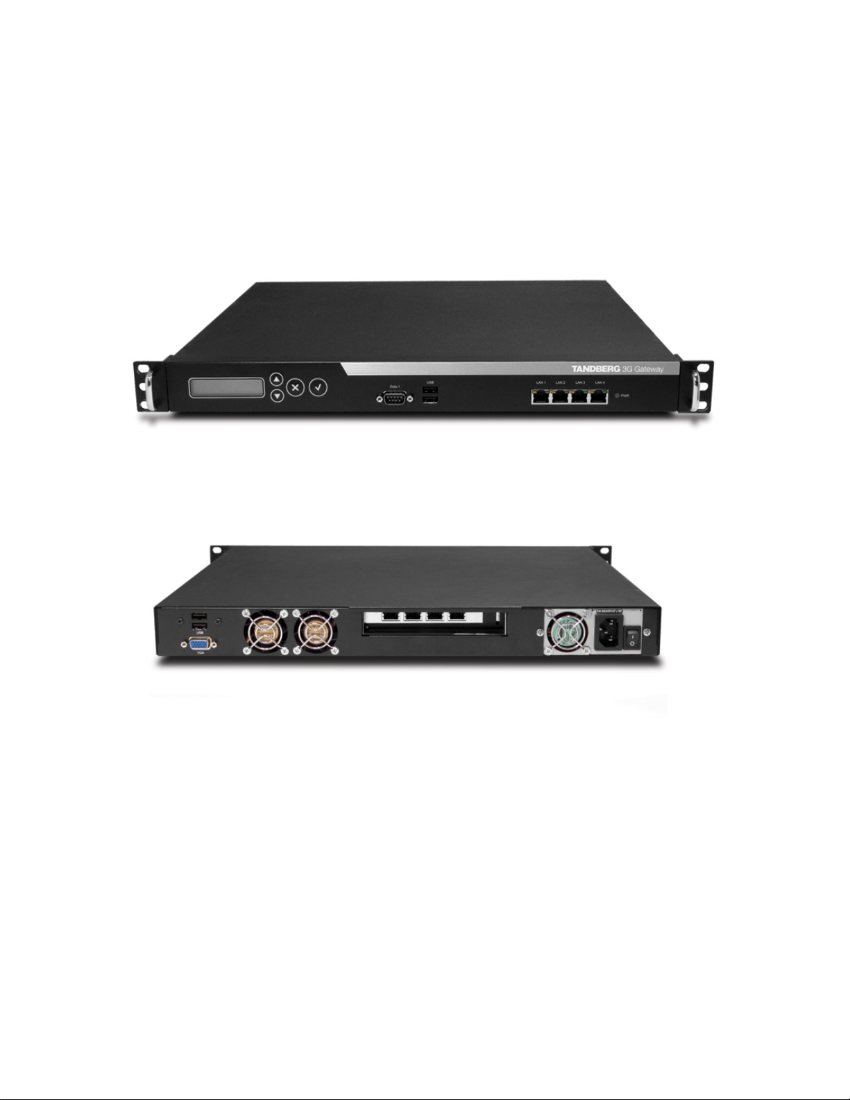
1.1 The TANDBERG 3G Gateway
Front view
The front panel provides 4 LAN interfaces, an LCD display, and an RS232 interface and control
buttons.
Rear view
The back panel provides four PRI interfaces, which can be activated individually by software
option keys, or 4 BRI interfaces depending on the configuration, one power switch/connector and
a VGA connector. Next to the PRI RJ-45 4 LED’s are mounted. In normal working condition the
green LED will be lit. Functions of the LED’s are:
Green: Normal operation
Red Alarm or Loss of signal (LOS) indicates that there is no signal and thus no framing info
received. A defect or unplugging the PRI cable will result in the same effect.
Yellow Alarm or Remote Alarm Indicator (RAI) means that the 3G Gateway is receiving framing
info, but in this framing info the other side tells the 3G Gateway that it is not reading the
gateway’s transmitted framing info. Typically, this may be a broken connector in the transmit (TX)
part of the PRI cable. This could also indicate weak or noisy signal in the transmit (TX) part of the
PRI cable.
10
Page 11

TANDBERG 3G Gateway User Manual
Blue Alarm indicates that the received frames are not synchronized properly.
No LED’s light up, indicates that layer one framing is working (right protocol like for example
EURO ISDN selected), however there is a problem at layer 2 caused by for example a CRC4
configuration mismatch.
1.1.1 3G GATEWAY Capacity – typical scenarios
Due to the fixed bandwidth of UMTS video telephony every call will be limited to 64 Kbit. This
offers a capacity of 30 simultaneous calls through a single PRI 3G Gateway or 8 calls through a 4
x BRI 3G Gateway. Due to audio transcoding (AMR to G.711) the bandwidth at IP side is 109
Kbit/s per session, 64 Kbit G.711 audio and 45 Kbit H.263 video. Depending on the option
package and version of the 3G Gateway (PRI or BRI) the amount of simultaneous 3G calls can
be less then 30 or 23 for T1.
11
Page 12

TANDBERG 3G Gateway User Manual
2 Installation
Precautions:
Never install telephone wiring during a lightning storm.
Never install telephone jacks in wet locations unless the jack is specifically designed for
wet locations.
Never touch uninstalled telephone wires or terminals unless the telephone line has been
disconnected at the network interface.
Use caution when installing or modifying telephone lines.
Avoid using a telephone (other than a cordless type) during an electrical storm. T here
may be a remote risk of electrical shock from lightning.
Do not use the telephone to report a gas leak in the vicinity of the leak.
The socket outlet shall be installed near to the equipment and shall be easily accessible.
Never install cables without first switching the power OFF.
This product complies with directives: LVD 73/23/EC, EMC 89/366/EEC, R&TTE
99/5/EEC.
This product complies with the standards GR-63-CORE and GR-1089-CORE and is
NEBS approved by UL .For NEBS compliance, the product should be installed in the
following manner:
There should be a clearance of 9.1cm between the product and any other product
mounted in the rack.
12
Page 13

TANDBERG 3G Gateway User Manual
2.1 Unpacking
To avoid damage to the unit during transportation, the 3G Gateway is delivered in a special
shipping box, which should contain the following components:
User Manual and other documentation on CD.
Rack-ears, screws and screwdriver.
Cables:
o Power cable
o One to four ISDN PRI cables, depending on the number PRI Option keys, or 4
ISDN BRI cables depending on the version.
o Ethernet cable
o RS232 cable
TANDBERG 3G Gateway
Installation site preparations
Make sure that the 3G Gateway is accessible and that all cables can be easily
connected.
For ventilation: Leave a space of at least 10cm (4 inches) behind the 3G Gateway’s rear
panel and 10cm (4 inches) in front of the front panel.
The room in which you install the 3G Gateway should have an ambient temperature
between 0
relative humidity.
Do not place heavy objects directly on top of the 3G Gateway.
Do not place hot objects directly on top, or directly beneath the 3G Gateway.
Use a grounded AC power outlet for the 3G Gateway.
You will need a CSU (Channel Service Unit) between your system and the PRI line from
your network provider.
Make sure that it is possible to receive and to make Mobile(h324M) video calls from
behind this line. Check this with your network operator!
If you are behind a PABX make sure that the PBABX is capable of routing Mobile
(H324M) video calls.
º
C and 35ºC (32ºF and 95ºF) and between 10% and 90% non-condensing
13
Page 14

TANDBERG 3G Gateway User Manual
2.2 Connecting cables
Power cable
Connect the system power cable to an electrical distribution socket.
ISDN PRI or BRI cables
The E1/T1 cable should be connected to a CSU (Channel Service Unit). You will need a CS U
between your 3G Gateway and the PRI line from your network provider.
LAN cable
To use the 3G Gateway on IP, connect a LAN cable from the ‘LAN 1’ connector on the 3G
Gateway to your network. The LAN 2, 3 and 4’ connector is not used and should be left open.
RS 232 cable
To control the 3G Gateway using the data port, connect an RS 232 cable between the 3G
Gateway’s RS 232 connector and the COM-port on a PC. For further information, please refer to
the paragraph ‘
2.3’ and the Data Port Command Interface User Guide.
14
Page 15
TANDBERG 3G Gateway User Manual
2.3 3G Gateway Configuration
The 3G Gateway requires some basic configurations before it can be used. It will be necessary to
find the IP-address and to create the dial-in and dial-out services program the ISDN-PRI Line
numbers.
It is possible to use the front panel LCD display or the serial RS232 cable. Using the RS232 cable
follow the instructions below:
1. Connect the RS232 cable between the 3G Gateway and a PC and then switch on the
3G Gateway.
2. Start a terminal program on the PC and configure it to: 115200, 8, 1, None.
3. a. To assign a static IP-address, type ‘Xconf ip Assigment: “Static” ’ and ‘Xconf Ip
address <IPAddr>’.
b. To assign an IP Subnetmask, type ‘Xconf ip address subnetmask <subnetmask>’.
c. To assign an IP Gateway address, type ‘Xconf ip address gateway <gateway IP-
address>’.
4. Restart the 3G Gateway.
5. Start a WEB browser and enter the IP-address of the 3G Gateway. Default password:
‘TANDBERG’.
6. To configure the 3G Gateway for UMTS dial in, enter PRI or BRI numbers and dial in
number(s). For details, see the ‘PRI Configuration’ and the ‘
section.
7. To configure the gateway for IP dial in, register the gateway to a gatekeeper and
enter H.323 services. For details, see chapter
The LCD panel makes it possible to configure and the Check the IP settings and to reboot the system. The
front panel LCD menu items are displayed below. Due to the limited amount of buttons the function will differ
on every menu level also depending on the function of the menu (reading or editing). Appendix 6.2 contains
a detailed description of every level and functions of every button. The usage of the buttons is designed in
an intuitive way and should not result in any problems.
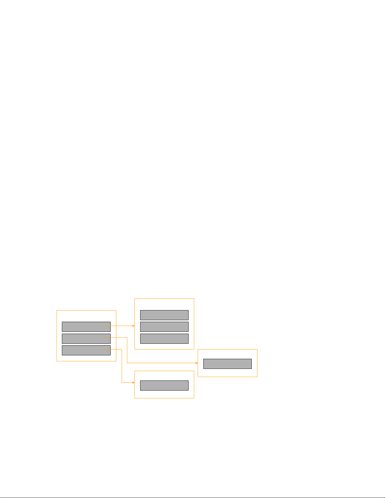
IP Settings
5.10, Services Configuration..
Services Configuration’
MainMenu
IP settings
IP Infor mati on
Commands
IP Address
IP Netmask
IP Default GW
IP Infor m a t i on
IP Address
Commands
Reboot
To configure the IP number, follow the instructions below:
1. Press any key to get the main menu.
2. IP settings should be displayed.
3. Press [ENTER] to access the IP settings menu.
4. Us the [UP/DOWN] key to select IP Address.
5. Press [ENTER] to access the IP address editing menu.
15
Page 16
TANDBERG 3G Gateway User Manual
6. Press [ENTER] again to get a cursor.
7. Use up down keys to navigate between the different digits.
8. After selecting a digit use the [ENTER] key in combination with the [UP/DOWN] key to change the
digit value.
9. When finished editing use [ESC] key to go to the confirm change menu.
10. Use the [UP/DOWN] key to select yes or no and [ENTER] to confirm.
11. Use [ESC] key to navigate back to the main menu.
Note that DHCP assigned IP-addresses are supported by the TANDBERG 3G Gateway (factory default),
3G Gateway start-up
To start the 3G Gateway, please make sure that the power cable is connected, and press the
power switch button at the back side to ‘1’.
On the front panel of the system the power indicator LED, marked ‘Pwr’, will turn GREEN.
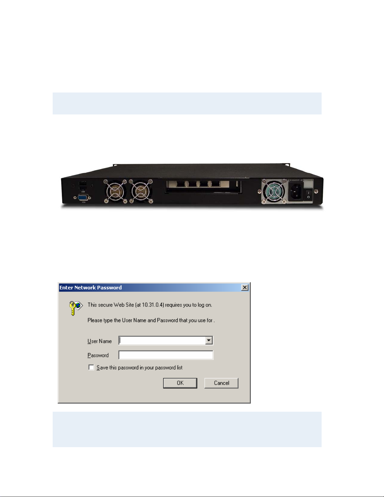
Accessing the 3G Gateway
You may access the 3G Gateway by entering the IP-address of the 3G Gateway in a standard
WEB-browser. You will then be asked to enter a password. It is not necessary to enter ‘User
Name’. The default password for the 3G Gateway is ‘TANDBERG’. Remember that the password
is case sensitive. Note that it also possible to use SSH and Telnet to configure the 3G Gateway.
Note that the password can be changed in System Configuration’, Misc’. See also the section ‘5.8
Miscellaneous Configuration’.
Forgot the password? Use the following procedure to set a new password:
16
Page 17

TANDBERG 3G Gateway User Manual
• Reboot the 3G Gateway.
• Connect to the 3G Gateway via the serial interface once it has restarted.
• Login with User Name pwrec. No password is required.
• One will be prompted for a new password.
The pwrec account is only active for one minute following a restart. Beyond that time the system will
have to be restarted again to change the password.
17
Page 18
TANDBERG 3G Gateway User Manual
3 Using the 3G Gateway
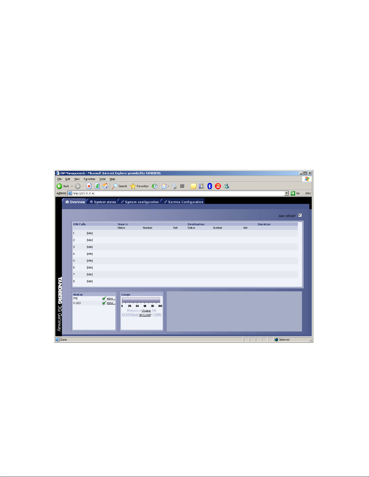
3.1 Call Overview
The System Status windows of the Gateway can be accessed via the default URL:
http://3G_Gateway_IP_Address/.
The ‘Overview’ window presents information about all calls routed through the 3G Gateway, i.e.
inbound and outbound numbers, duration of the call and call status, like ringing (alerting),
connecting and connected.
GW Calls
Shows all active calls through the 3G Gateway.
[Idle] No call is active.
Active Call A call is active.
Source / Destination
18
Page 19

TANDBERG 3G Gateway User Manual
Source shows the Status of the incoming call to the 3G Gateway, the number and which network
the incoming call is using.
Destination shows the Status of the outgoing call from the 3G Gateway, the number and which
network the outgoing call is using.
Idle No active call, call has been disconnected.
Alerting Call is being connected, i.e. ringing state.
Connected Call is connected.
Number ISDN or IP number.
IP/H.323 Call connected is using the H.323 protocol over IP.
Duration
Shows the length of the current call.
Status
Shows current status of the PRI and IP status.
PRI:
PRI line is synced and active. Click on More... to see status in detail.
PRI line is not active. Click on More... to see status in detail.
IP/H.323:
The gateway is registered with a Gatekeeper. Click on More... to see status in
detail.
The gateway is not registered with a Gatekeeper. Click on More... to see status in
detail.
Usage
The usage bar shows the current status of all the available resources (CPU, ISDN channels and
number of calls)
When the Resource Usage reaches the “Busy on Load”-limit, the gatekeeper will try to route
outgoing IP calls to other gateways. This is done to maintain availability for incoming UMTS calls
when using multiple gateways.
Resource Usage 90%. Click on the Usage link to see resource usage
in detail.
H.323 Busy on Load> 70%. Click on the Load link to adjust the value.
19
Page 20

TANDBERG 3G Gateway User Manual
3.2 Dial from UMTS
The 3G Gateway supports three different UMTS Dial In services:
- “DiD” Æ Direct Inward dialing from a 3G handset.
- “IVR” Æ Dialing terminals from a 3G handset via a selection menu.
- “Phonebook” Æ Selecting an entry from a gateway phone book.
Any of these services can be enabled or disabled, but at least one must be enabled for incoming
call routing to take place.
In order to enable parallel incoming calls, a PRI number range must be defined.
For more details on UMTS Dial-In services, please see the section ‘5.10 Services’.
DID
Direct Inward Dialing (DID) will provide you with direct ISDN numbers for your IP endpoints i.e. it
will do a direct mapping between your ISDN number and an H.323/SIP Alias or vice versa. In
order to use DID you will need to have assigned multiple ISDN numbers to your ISDN PRI or BRI
line, as each ISDN number will map to a single IP endpoint.
Example:
Your ISDN number range is from 67124000 to 67124050 and DID is enabled.
You want your IP endpoints to have the numbers (H.323 Alias) in the range 94000 -
94050.
In the services Configuration, set (remove) Prefix/Nr to 67124, set Service Type to
DiD and (add) Prefix/Nr to 9.
To call an IP endpoint with H.323 Alias 94020 from ISDN, dial the ISDN number
67124020.
The gateway starts to call the IP endpoint and the “connecting” picture and sound are
activated.
When the call is connected audio and video are transmitted through the gateway.
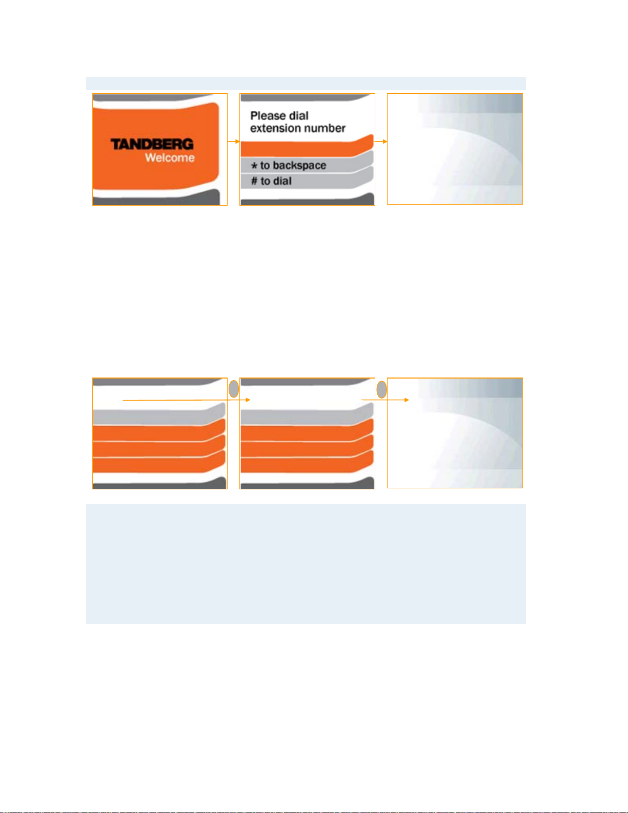
IVR
Interactive Video Response (IVR), also called extension dial-in, is an automated answering
system that directs the call to the IP endpoint indicated by the caller. The caller uses telephone
tones (DTMF) to enter the H.323/SIP Alias or extension.
IVR is useful if you have limited numbers on your ISDN PRI or BRI line.
Example:
A videoconferencing system calls into the Extension Dial In number with IVR active.
The gateway activates the ‘Welcome’ picture and sound.
The videoconferencing system enters the extension (H.323 Alias) followed by the #
(pound-sign) to indicate end of number.
The gateway starts to call the IP endpoint and the “Connecting” picture and sound are
activated.
When the call is connected audio and video are transmitted through the gateway.
20
Page 21
TANDBERG 3G Gateway User Manual
connecting
IVR Phonebook IVR Phonebook allows an UMTS phone to dial an IP endpoint directly, without
knowing or having to (manually) enter the extension number via DTMF. IVR Phonebook is a dialin method, which combines a directory listing from TMS with IVR. In this mode the user can
search in the global address book provided via TMS using the alphanumeric part of the keypad.
The 3G Gateway supports T9 phonebook and starts displaying the 5 entries which match with the
submitted characters as displayed below. Pressing 2 and 3 will result in a list with names
containing the combinations ‘ad’, ‘be’, ‘ce’, etc. For example trying to reach Allan.Bjornstad is
possible pressing the 2 and the 5 on the keyboard. This will result in a listing of names which
contain ‘al’. A valid list will contain both alisdair.munro and anne.aalbuk. The top name in the list
is highlighted and via the pound key (#) this person will be dialed. In case the name is not listed
pursue in completing the name using the T9 concept known from SMS. The star (*) key on the
keyboard is used as backspace.
l
al
Alfredo.Truji
Alisandair.munro
Allan.bjornstad
Ball.klorin
* Backspace # dial
Example:
An UMTS phone calls into the Extension Dial In number with IVR phonebook active.
The gateway shows a menu which makes it possible to submit the name (both
Christian and first name) via the alphanumeric DTMF keys . For example finding
Michel is possible via pressing 6 (m,n,o),4 ,2. The top entry in the phonebook will be
highlighted and pressing ‘#’ will starts to call the IP endpoint, the “Connecting” picture
and sound are activated.
When the call is connected audio and video are transmitted through the gateway.
Sequence of Services
To ensure best service to the incoming UMTS call, the gateway will first try to match the DID
number, and then the IVR Phonebook number.
all
Allan.bjornstad
Ball.klorin
Ben.hockley
Demowall-nor
* Backspace # dial
#
connecting
21
Page 22

TANDBERG 3G Gateway User Manual
3.3 Dial from IP
IP endpoints and MCUs can call out through the gateway by using one of the services defined on
the gateway. The gateway supports three different dial out services:
- “DiD” Æ Direct Inward Dialing to a 3G handset.
- “IVR” Æ Dialing 3G terminals via a selection menu.
- “Phonebook” Æ Selecting an entry from a gateway phonebook.
Services
Service prefixes are used for IP endpoints to access UMTS Handsets. Up to twenty
services/prefixes can be defined, but we recommend using one single prefix for simplicity.
Example:
An H.323 Service prefix for outgoing video calls is defined as “0”.
The IP endpoint dials 067121212 to dial the UMTS number 67121212.
The gateway starts to call the UMTS handset and the “Connecting” picture and sound
are activated.
Audio and video are transported through the gateway when the call is connected.
For more details on H.323 Services, please see ‘5.10 Services’.
22
Page 23

TANDBERG 3G Gateway User Manual
Note that the bandwidth used for the call will be 109Kbit independent of the bandwidth
selected on the IP endpoint, except for selecting 64 Kbit. However this will result in an audio
only call.
23
Page 24

TANDBERG 3G Gateway User Manual
4 View System Status
To view current gateway status, open ‘System Status’ as shown in the figure below.
4.1.1 ISDN PRI/BRI Status
PRI Status
The colored part of the system status indicates the condition of the ISDN PRI line. There are
three possible conditions:
• Sync 30 of 30. ISDN layer 1 and 2 are up and in sync.
• Sync 0 of 0, ISDN layer 1 and 2 are in sync but not up.
• Red Alarm, 0 of 0, ISDN layer 1 and 2 are down, mostly indicating a disconnected ISDN
line.
Besides the indications on the webpage the ISDN interface also contains 4 LEDs, located at the
back-side of the 3G Gateway.
24
Page 25

TANDBERG 3G Gateway User Manual
These LEDs indicate the following PRI status:
Green: Normal operation
Red Alarm or Loss of signal (LOS) indicates that there is no signal and thus no framing
info received. The same effect will be obtained by pulling out the PRI cable. This may
also be caused by a broken connector in the receiver (RX) part of the cable.
Yellow Alarm or Remote Alarm Indicator (RAI) means that the gateway is receiving
framing info, but in this framing info the other side tells the gateway that it is not reading
the gateway’s transmitted framing info. Typically, this may be cause by a broken
connector in the transmitter (TX) part of the PRI cable. This could also indicate weak or
noisy signal in the transmitter (TX) part of the PRI cable.
Blue Alarm indicates that the received frames are not synchronized properly.
No LEDs light-up indicates that layer one framing is working (right protocol like for
example EURO ISDN selected). However there is a problem at layer 2 caused by for
example a CRC4 configuration mismatch.
BRI Status
The picture below shows the status page of a BRI version of the gateway.
25
Page 26

TANDBERG 3G Gateway User Manual
The BRI status displays the conditions of ISDN layer 1 and 2 separately. Green indicates up and
in sync. Red indicates not in sync and indicate probably a disconnected ISDN line.
Besides the indications on the webpage each ISDN BRI interface located at the back-side of the
3G Gateway has a green and orange LED. The meanings of these LEDs are:
Green: Layer 1 of the ISDN signaling is up.
Green and Orange indicates that both layers 1 and 2 are up. Insome countries the
orange LED can blinks on a regular interval, or is turned on when there is an active call.
No LEDs light-up indicates that there is no connection or a wrong wired connection.
Note that in some countries layer 2 can be down when there is no activity (ongoing
connections). However, layer 2 should become active when a call is made or re ceived.
Note that in case the BRI 3G Gateway is connected with less then 4 BR lines, the BRI
interfaces with the highest number(s) should be left open. For example when only 2 ISDN
lines are used they should be connected with interface 1 and 2.
26
Page 27

TANDBERG 3G Gateway User Manual
4.1.2 H.323 Status
To view H.323 gatekeeper status, open ‘H.323 Status’ as shown in the figure below.
Note that, since this target system is not an endpoint it is not possible to use this IP address to
place calls to or through the 3G Gateway.
IP Address Shows the IP address of the 3G Gateway.
H.323 Gatekeeper Status Shows status and IP address of the Gatekeeper, the 3G
Gateway is registered to. ‘Inactive’ means the 3G Gateway is
not registered to a Gatekeeper. ‘Registering’ means the 3G
Gateway has problems registering with the selected Gatekeeper.
4.1.3 System Information
To view 3G Gateway information, open ‘System Information of the System status tab, as shown
in the figure below. This page provides an overview of installed software and hardware.
27
Page 28

TANDBERG 3G Gateway User Manual
4.1.4 Available Resources
To view available resources of the 3G Gateway, open ‘Available Resources’ of the System status
tab, as shown in the figure below.
This tab shows the actual System Load, the amount of video calls and the amount of available
ISDN channels. These figures depend on the system’s resource use. Note that available System
Load 100% indicates no load on the 3G Gateway.
28
Page 29

TANDBERG 3G Gateway User Manual
5 Configure the 3G Gateway
To configure the 3G Gateway, open ‘System Configuration’ tab, as shown in the figure below. In
the system configuration window 9 tabs can be distinguished, i.e. PRI, SS7, IP, H.323, SIP, Video
Portal, SNMP, Misc and Upgrade. The underlying settings of the aforementioned links will be
discussed in paragraphs
5.1 - 5.9, respectively.
5.1 ISDN PRI/BRI Configuration
The first link of system configuration tab is either PRI or BRI, depending on the ISDN hardware
configuration of the 3G Gateway. Paragraphs
settings, respectively.
5.1.1 PRI Configuration
5.1.1 and 5.1.2 will elaborate on the PRI and BRI
To configure the PRI, select ‘System Configure - PRI’ as shown in the figure below.
PRI Protocol
Select between the following PRI protocols:
ETSI (Euro ISDN)
National ISDN
AT&T Custom
Japan/Taiwan ISDN
SS7 (Only available when enabled with option key)
Save
When all settings are entered, please press the ‘Save’ - button to store the new settings.
Note changing from E1 to T1 configuration requires a restart of the unit.
29
Page 30
TANDBERG 3G Gateway User Manual
Interface Configuration
This section configures the PRI or ISDN interface.
PRI CRC-4
Used for most E1-PRI configurations. If your network equipment does not support this feature,
switch off PRI CRC-4.
Bearer capabilities
Within ISDN different bearer capabilities are used to signal the type of data (Voice, Data, H320,
H324M), which is used by switches and other equipment to determine what to do with the data or
the call (compressing voice data neglect etc).
• Incoming: sets the ISDN bearer capability of the incoming 3G calls.
o UDI: In some situations the non correct UDI (Unrestricted Digital Information)
bearer is used in stead of the right H324M capability. This setting makes it
possible to accept incoming 3G calls with UDI bearer signaling.
o ALL: Means that calls independent of their bearer capabilities are accepted. This
makes it even possible to accept audio calls.
• Outgoing: sets the ISDN bearer capability for the outgoing 3G calls.
o H324M: This ITU standardized capability is selected for outgoing calls by default.
o UDI: In some situations the switch does not accept calls which use the correct
H324M capability. This setting makes it possible to use the gateway in these
situations via selecting UDI.
Low Channel
Indicates the lowest numbered E1/T1 B-channel the system is allowed to use for each PRI-line
when selecting channels for outgoing calls. Presently, this setting has no effect.
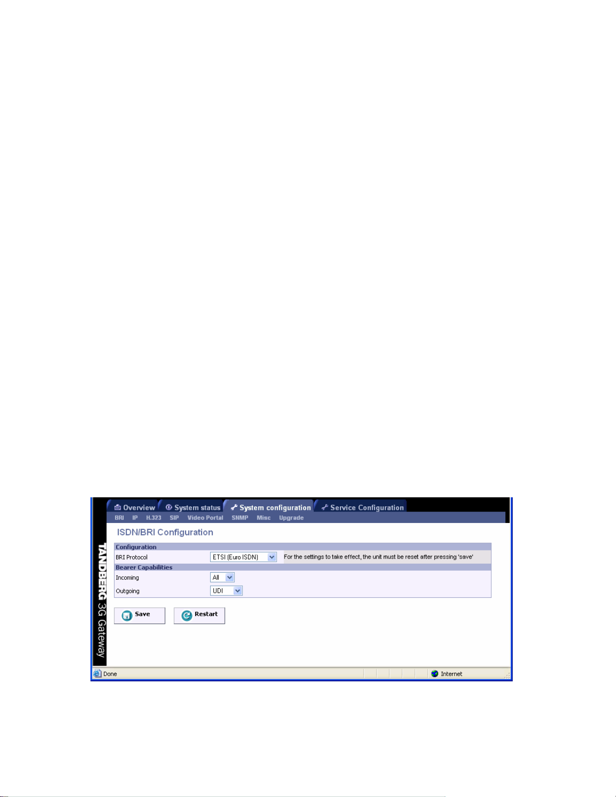
5.1.2 BRI configuration
To configure the 4 BRI ports, select ‘System Configure - BRI’ as shown in the figure below.
BRI Protocol
Select between the following BRI protocols:
30
Page 31

TANDBERG 3G Gateway User Manual
ETSI (Euro ISDN)
National ISDN
AT&T Custom
Japan/Taiwan ISDN
Bearer capabilities
Within ISDN different bearer capabilities are used to signal the type of data (Voice, Data, H320,
H324M), which is used by switches and other equipment to determine what to do with the data or
the call (compressing voice data neglect etc).
• Incoming: sets the ISDN bearer capability of the incoming 3G calls.
o UDI: In some situations the non correct UDI (Unrestricted Digital Information)
bearer is used in stead of the right H324M capability. This setting makes it
possible to accept incoming 3G calls with UDI bearer signaling.
o ALL: Means that calls independent of their bearer capabilities are accepted. This
makes it even possible to accept audio calls.
• Outgoing: sets the ISDN bearer capability for the outgoing 3G calls.
o H324M: This ITU standardized capability is selected for outgoing calls by default.
o UDI: In some situations the switch does not accept calls which use the correct
H324M capability. This setting makes it possible to use the gateway in these
situations via selecting UDI.
Note that it is not possible to configure ISDN BRI lines for special functions like dial out only.
The gateway will automatically select a free BRI line for H323 to 3G calls and possibly block a
DiD or an IVR menu when the BRI lines have different numbers. It is therefore strongly
recommended that all ISDN BRI lines have the same number range. Contact your ISDN or
telecom supplier about numbering plans of ISDN lines.
31
Page 32

TANDBERG 3G Gateway User Manual
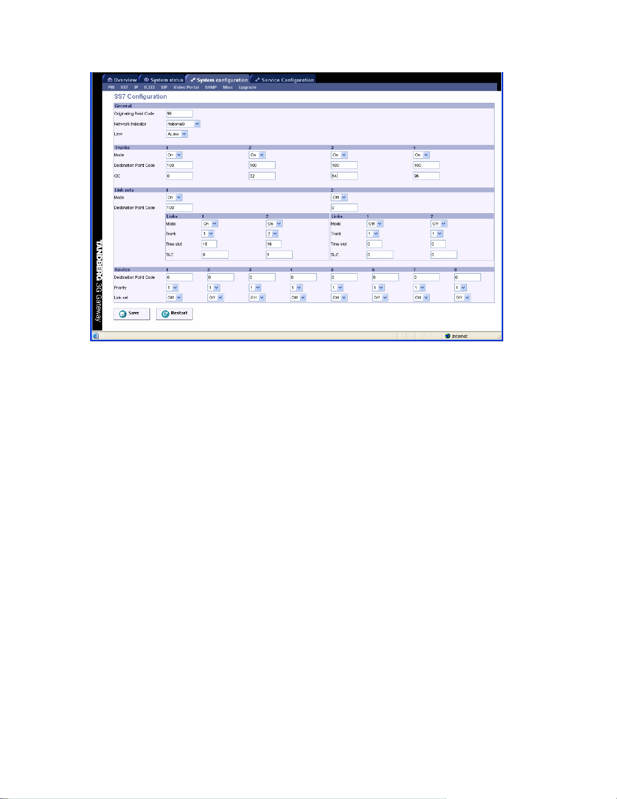
5.2 SS7 Configuration
To configure the Signaling System 7 (SS7 signaling) of the ISDN SS7 trunks click the ‘SS7’ link of
the ‘System configuration’ tab, as depicted in the figure below.
General
• Originating Point Code (OPC). A number between 0-2
signaling point, in this case the 3G Gateway, within a telephone network. This number
consists of three parts, i.e. a network, cluster and member number, and will be provided
by the network operator.
• Network indicator. A two bit data field within the Service Information Octet of the
Message Signal Unit that permits discrimination between national and international
messages.
• Law. Either ALAW or ULAW. An a-law algorithm is a standard companding, i.e.
compressing and expanding, algorithm, used in European digital communication systems
to optimize, i.e. modify, the dynamic range of an analog signal for digitizing. The µ-law
algorithm is similar to a-law and used in North American and Japanese systems.
Trunks
A maximum of four PRI’s or SS7 trunks, i.e. cables carrying E1/T1, can be enabled in the 3G
Gateway.
• Mode. Enable or disable a trunk.
• Destination Point Code (DPC). Uniquely identifies the destination signaling point of the
trunk. It will be provided by the network operator.
• CIC. The Circuit Identification Code is a unique identifier for a data time slot in a cable
(trunk). In this case the CIC acts as base address and can be defined for each SS7 trunk
and sets the first time-slot number of the respective SS7 trunk.
Link sets
A link is a time slot within a trunk used for signaling. Link sets are typically used for signaling failover purposes to one switch.
• Enabled. Checking this box enables at least one signaling link in a link set.
• Destination Point Code. Uniquely identifies the destination signaling point of the link.
This can differ from the DPC of the trunk, e.g. the DPC of a Signaling Transfer Point
(STP), see example 2 below.
o Enabled. Link1 is checked by default. Whereas, a second link box can be
checked to define an extra signaling link for fail-over purposes.
o Trunk. Number of the trunk (1 - 4) in which a time slot is reserved for signaling.
o Time slot. Number of the time slot, within aforementioned trunk, reserved for
signaling.
o SLC. A Signaling Link Code is a unique link number provided by the network
operator to identify a link.
Routes
Routes are typically used for signaling fail-over purposes via multiple switches.
• Destination Point Code. Unique identifier indicating the destination signaling point of a
trunk.
• Priority. Priority level of the route to the destination signaling point. Fail-over signaling
paths will be followed according to this priority.
• Link set. Indicates the link to the destination signaling point according to the above
mentioned priority setting. When set to off the respective route is disabled.
14
, which uniquely identifies a
32
Page 33

TANDBERG 3G Gateway User Manual
Save
When ready to store the new settings, press ‘Save’. These settings will take effect when the
system has been restarted.
Restart
This button will restart the 3G Gateway. Any changes made in the SS7 Configuration of the 3G
Gateway will take effect after the system has been restarted.
The following two examples will explain the above mentioned SS7 settings.
Example1
Suppose all 4 SS7 trunks of one 3G Gateway are connected to one switch, as indicated in the
connection schematic below. In this example the Originating point code (OPC) of the 3G
Gateway, equals 99 and the Destination Point Codes (DPCs) for all trunks equal 100. Both OPC
and DPC are provided by the telephone network operator. These settings can be seen in the
schematic and in the screen shot of the SS7 window below. All trunks can carry a maximum of 30
calls, i.e. 30 data time slots. Each data time slot is identified uniquely by its OPC, DPC and Circuit
Identification Code (CIC). The “absolute” CIC consist of a CIC “base address”, which has to be
defined for each trunk in the SS7 window, i.e. in this case 0, 32, 64 and 96, and a relative
address. The latter is a number between 0 and 31 and depends on the choi ce of the framing time
slot and signaling time-slot numbers. Since one time slot is reserved for framing, in this case set
to time slot 0 by default, and one time slot has to be defined for signaling (16 in this example), 30
time slots are left to transport call related data, i.e. time slots with relative addresses 1-15 and 1731, see the table in the schematic below.
In the 3G gateway for signaling fail-over purposes a maximum of 2 SS7 trunks, also called links,
can be defined to take care of the SS7 signaling of all 4 trunks. In this case trunks 1 and 2 are
used for SS7 signaling. Since, there exists a direct connection between the 3G Gateway and the
switch, both links are defined in the same link set with the DPC of the switch, i.e. 100. Since, failover has been arranged within one link set, no routes can be defined.
33
Page 34
TANDBERG 3G Gateway User Manual
Example2
Suppose 2 out of 4 trunks are connected to one switch and the other 2 to another switch. Now
SS7 signaling fail-over is arranged via two switches and two Signaling Transfer Points (STPs)
over 2 link sets, as can be seen from the schematic and the SS7 window below. Since the trunks
are terminated by the switches, the DPCs of trunk 1 and 2 are 100 and 101, respectively.
However, both links are terminated by the STPs. Link set 1 contains SS7 trunk 1 and is
terminated by an STP with DCP 200. Link set 2 contains SS7 trunk 3 and is terminated by an
STP with DCP 201. For each link 2 routes are available to 2 switches, one directly and one via an
STP. Priority 1 is assigned to all direct links, whereas all links via STPs have the lower priority 2.
34
Page 35

TANDBERG 3G Gateway User Manual
35
Page 36

TANDBERG 3G Gateway User Manual
36
Page 37

TANDBERG 3G Gateway User Manual
5.3 IP Configuration
To configure the IP settings on the 3G Gateway, open ‘IP’ as shown in the figure below.
IP Configuration Interface1
IP Address Assignment
DHCP: Dynamic Host Configuration Protocol can be selected when a DHCP server is
present. Static IP Address, Static IP Subnet Mask and Static IP Gateway are
ignored because these parameters are assigned by the DHCP server.
Static: If Static assignment is used, the 3G Gateway’s IP address and IP subnet mask
and the Gateway’s IP address must be specified in the respective IP address
fields.
Address
The Static IP Address defines the network address of the 3G gateway. This address is only used
in static mode. Your LAN administrator will provide you with the correct address for this field.
Subnet Mask
The Static IP Subnet Mask defines the type of network. Your LAN administrator will provide the
correct value for this field.
Gateway
The Static Gateway IP address is set to 127.0.0.1 by default. In case of a router enter its address
here. Your LAN administrator will provide the correct value for this field.
37
Page 38

TANDBERG 3G Gateway User Manual
Ethernet Speed
• Auto The gateway will automatically detect the speed/duplex on the LAN.
• 10Half The gateway will connect to the LAN using 10 Mbps/Half Duplex.
• 10Full The gateway will connect to the LAN using 10 Mbps/Full Duplex.
• 100Half The gateway will connect to the LAN using 100 Mbps/Half Duplex.
• 100Full The gateway will connect to the LAN using 100 Mbps/Full Duplex.
DNS Interface1
Up to five Domain Name Server IP addresses can be specified here. Your LAN administrator will
provide the correct values for these fields. By default these fields are set to 127.0.0.1
Date and Time Settings
An NTP server address can be specified here to provide the 3G gateway with uptodate time and
date information.
Save
When ready to store the new settings, press ‘Save’. These settings will take effect when the
system has been restarted.
Restart
This button will restart the 3G Gateway. Any changes made in the IP Configuration of the 3G
Gateway will take effect after the system has been restarted.
38
Page 39

TANDBERG 3G Gateway User Manual
5.4 H.323 Configuration
To dial out from IP to ISDN, through the 3G Gateway, requires the use of H.323 numbers (E.164
aliases). This means that the 3G Gateway must be registered to a Gatekeeper.
H.323 Gatekeeper Status shows the current status of the Gatekee per registration.
Note that if the Gatekeeper is configured with an alternative Gatekeeper, the Status area
might report a registration to the IP address of the alternative Gatekeeper.
Gatekeeper Settings
Gatekeeper Mode Enables the 3G Gateway to register to a Gatekeeper or without (direct
mode). Selecting direct will gray out the gatekeeper IP address settings.
When registered with a gatekeeper, the H.323 Gatekeeper Status shows
Registered, Gatekeeper’s IP address and what port used.
Selecting direct mode will result in no Gatekeeper registration; hence it is not
possible to dial through the 3G Gateway via alias names. The H.323 Gatekeeper
Status area will be empty.
Problems with registration will be shown in the Status area and as a Red alarm
on the ‘Overview’ page.
Gatekeeper IP Address
Enter the Gatekeeper IP Address that the 3G Gateway should register to. Leaving empty will
result in direct dialing without the use of aliases.
39
Page 40

TANDBERG 3G Gateway User Manual
Authentication Mode
Off Register to the Gatekeeper without authentication.
Auto Register to the Gatekeeper with H.235 authentication using ID/Password given below.
Authentication ID, Password
Enter the ID and password required to perform H.235 authentication at the Gatekeeper.
To register to a Gatekeeper that requires authentication, an NTP server has to be configured.
Note in case password is empty the 3G Gateway will still use the Authentication ID to register
with the gatekeeper. However, when the Authentication ID is left empty, the System Name
field (see paragraph 5.8) will be used to register the 3G Gateway with the gatekeeper in stead.
In case both the Authentication ID field and the System Name field are empty the 3G Gateway
can not be registered with the gatekeeper.
40
Page 41

TANDBERG 3G Gateway User Manual
5.5 SIP Configuration
SIP settings
Mode When set to “On” the 3G Gateway is registered to the SIP proxy.
Proxy
SIP proxy address Enter the IP Address of the proxy server the 3G Gateway should register
to.
SIP proxy port Enter the port number belonging to the above mentioned proxy IP
address.
Note that setting the Mode “Off” won’t hide the SIP proxy address and port settings
Save
When ready to store the new settings, press ‘Save’. These settings will take effect when the
system has been restarted.
Restart
This button will restart the Video Portal. Any changes made with respect to the SIP settings of the
3G Gateway will take effect after the system has been restarted.
41
Page 42
TANDBERG 3G Gateway User Manual
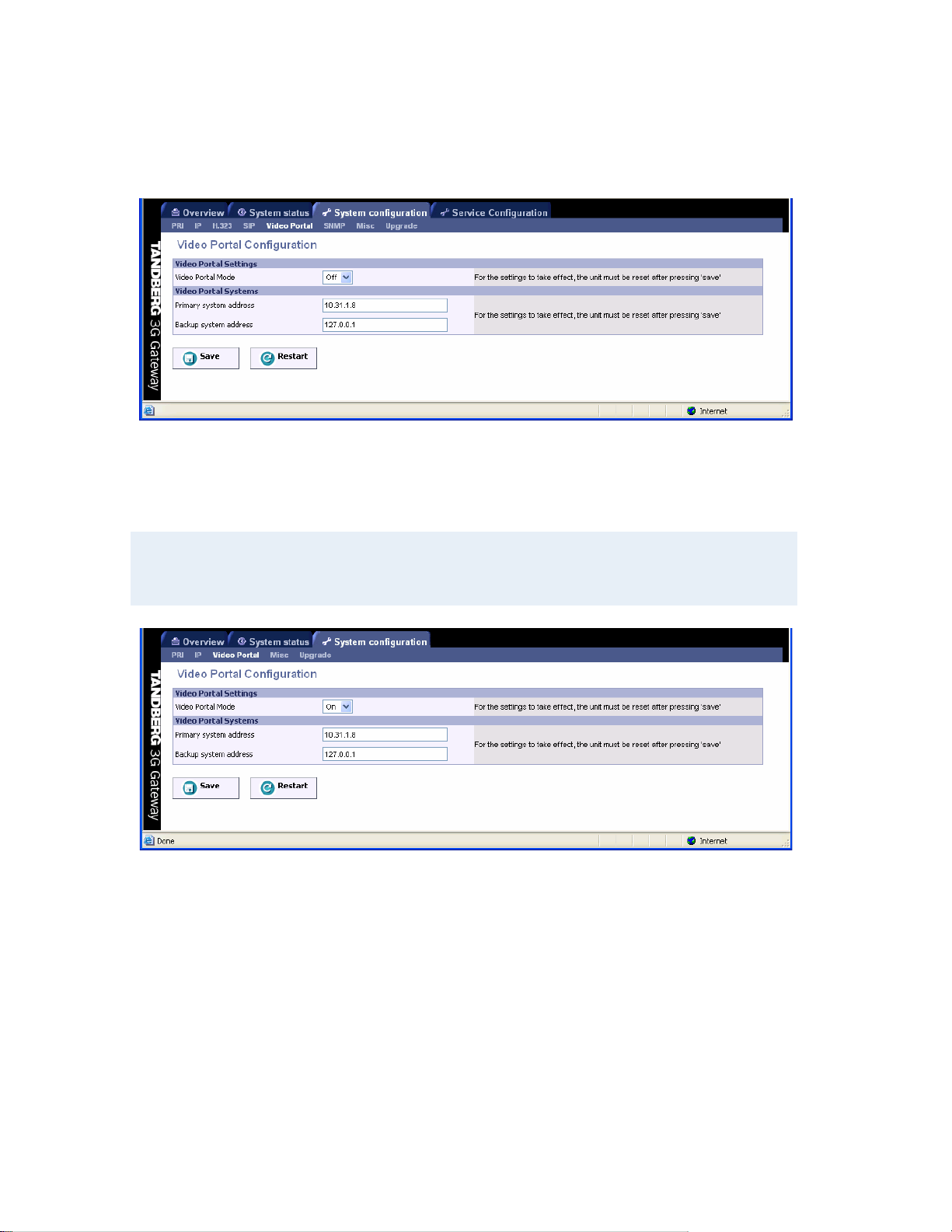
5.6 Video Portal Configuration
Video Portal Settings
Video Portal Mode When set to “Off” the 3G gateway will operate standalone.
However, if it needs to be configured in tandem operation with a
Video Portal the mode has to be set to “On”.
Note that setting the Video Portal Mode “On” all H323, SIP related tabs as well as the Service
Configuration tab will disappear from the window (See figure below).
Video Portal Systems
Primary system address Enter the IP Address of the Video Portal the 3G Gateway should
register to.
Backup system address Enter the IP Address of the backup Video Portal the 3G Gateway
should register to.
Save
When ready to store the new settings, press ‘Save’. These settings will take effect when the
system has been restarted.
Restart
This button will restart the 3G Gateway. Any changes made with respect to the Video Portal
settings of the 3G Gateway will take effect after the system has been restarted.
42
Page 43

TANDBERG 3G Gateway User Manual
5.7 SNMP Configuration
SNMP (Simple Network Management Protocol) is used for monitoring and configuring different
units in a network. The 3G Gateway’s SNMP Agent responds to requests f rom SNMP Managers
(a PC program etc.). SNMP traps are generated by the agent to inform the manager about
important events.
Configuration
SNMP Mode
The SNMP operation modus can be set to:
• On, turn SNMP on;
• Off, turn SNMP off;
• ReadOnly, Do not send SNMP information to the host;
• TrapsOnly, Only send SNMP information identified as TRAPS to the host.
SNMP Community name
SNMP Community names are used to authenticate SNMP requests. SNMP requests must have
this ‘password’ in order to receive a response from the SNMP agent in the 3G Gateway.
Note that the SNMP Community name is case sensitive.
System contact
Used to identify the system contact via SNMP tools such as HPOpenView or TANDBERG
Management Suite.
43
Page 44

TANDBERG 3G Gateway User Manual
System location
Used to identify system location via SNMP tools such as HPOpenView or TANDBERG
Management Suite.
SNMP Trap Host (1, 2 and 3)
Identifies the IP-address of the SNMP manager. Up to three different SNMP Trap Hosts can be
defined. Your LAN administrator should provide the correct values for these fields.
Save
Press ‘Save’ to activate the new settings.
44
Page 45
TANDBERG 3G Gateway User Manual
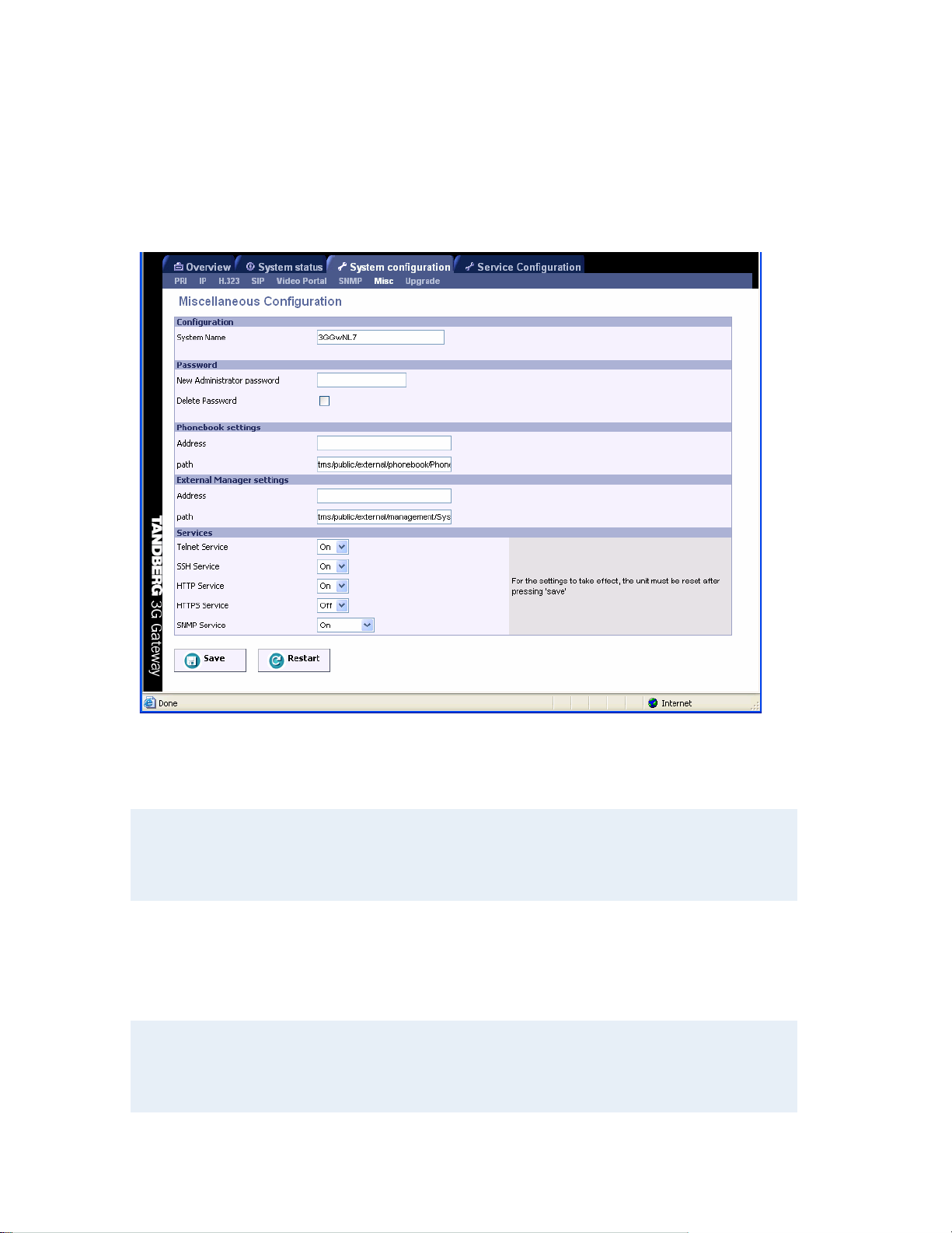
5.8 Miscellaneous Configuration
To configure the miscellaneous settings on the 3G Gateway, open ‘Misc’ as shown in the figure
below.
Configuration
To change the system name of the 3G Gateway, enter the new system name in the ‘System
Name’ field.
Note that when the Authentication ID in the H.323 link (see paragraph 5.4) is left empty, the
System Name field will be used to register the 3G Gateway with the gatekeeper in stead. In
case both the Authentication ID field and the System Name field are left empty the 3G
Gateway can not be registered with the gatekeeper.
Password
To change the system password of the 3G Gateway, enter the new password in the ‘New
Administrator Password’. To delete the existing password, select ‘Delete Password’.
Note:
Forgot the password? Use the following procedure to set a new password:
• Reboot the 3G Gateway.
• Connect to the 3G Gateway via the serial interface once it has restarted.
45
Page 46

TANDBERG 3G Gateway User Manual
• Login with User Name pwrec. No password is required.
• One will be prompted for a new password.
The pwrec account is only active for one minute following a restart. Beyond that time the system will
have to be restarted again to change the password.
Phonebook settings
To enable a phonebook in the 3G Gateway it is required to configure a TMS server. Enter both
the IP address and the phonebook path.
External Manager settings
To enable cooperation between the 3G Gateway and an external TANDBERG Management
System (TMS) enter both its IP address and its path.
Services
The different IP services on the 3G Gateway - Telnet, Telnet Challenge, HTTP, HTTPS and
SNMP can be disabled independently to prevent access to the system.
In addition, the SNMP Service Read Only/Traps Only will make it possible to read SNMP
messages in addition to enable/disable SNMP.
Save
Press ‘Save’ and thereafter the ‘Restart’ to activate the new settings.
46
Page 47
TANDBERG 3G Gateway User Manual
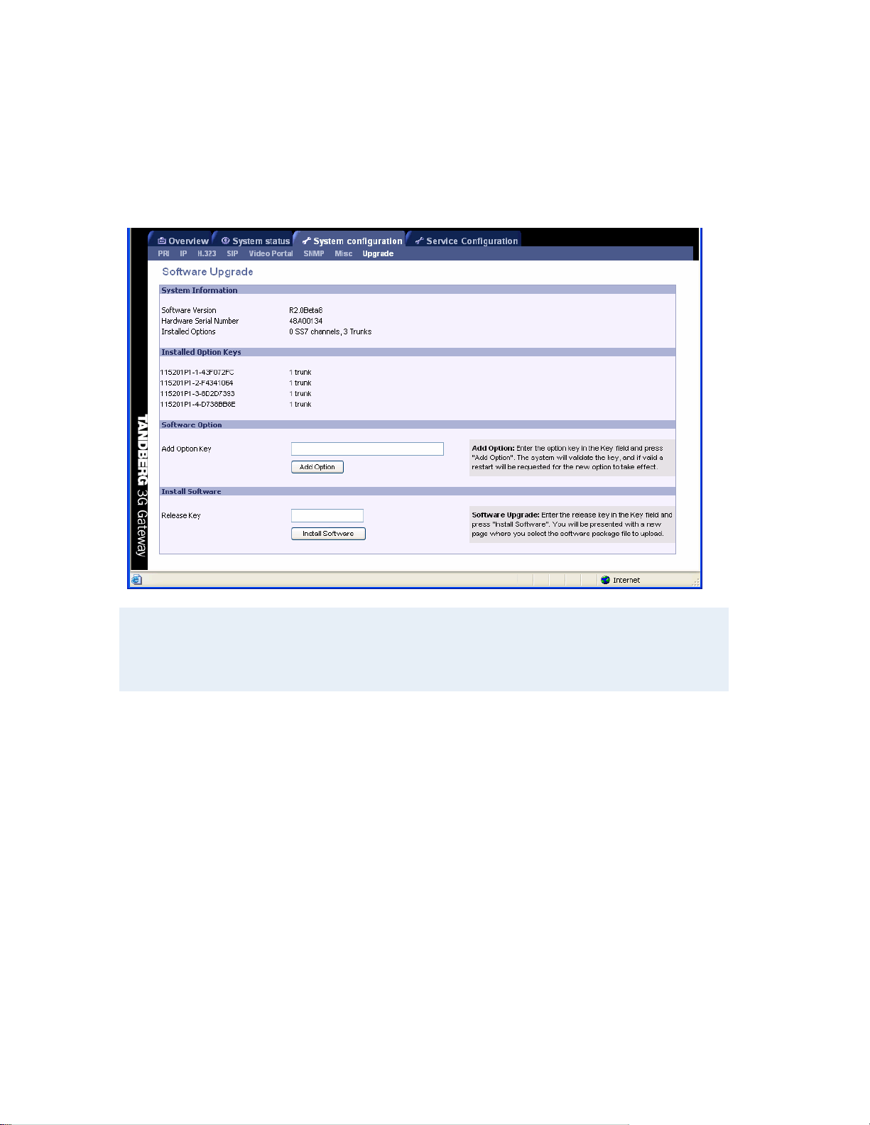
5.9 Software Upgrade
Software upgrade is where new software to the gateway can be installed from. It also shows
current software version and the gateway’s hardware serial number.
Note that to upgrade the 3G Gateway, a valid Release key and Software file is required. To
expand software options additional Option keys are required. Contact your TANDBERG
representative for more details.
System Information
Software Version Shows the currently installed Software version.
Hardware Serial Number This unique i dentifier number for the Video Portal must
be provided when ordering Software Upgrade.
Installed Options Shows the currently installed Options.
Installed Option Keys Shows the installed options per option key.
Software Option Enter the supplied option keys and press ‘Add Option’.
Note that the new options take effect after the next
reboot.
Install Software
Release Key Enter the release key in the Key field and press ‘Install Software’. A new window
will be presented, which enables the entry of the software package, i.e. a .pkg, file to be uploaded
(See figure below).
47
Page 48

TANDBERG 3G Gateway User Manual
After the .pkg file has been selected, this will be uploaded into the flash memory of the 3G
Gateway, showing the screen below.
In case of an incorrect Release Key, the original software will not be replaced; an error message
is generated as presented in the figure below.
48
Page 49

TANDBERG 3G Gateway User Manual
49
Page 50

TANDBERG 3G Gateway User Manual
5.10 Services Configuration
Dialing rules for both UMTS handsets, H.323 and SIP endpoints are configured via the services
menu. In the services menu the following services types are distinguished:
• “DiD” ÆDirect inward dialing H.323/SIP endpoint or 3G terminal.
• “IVR” ÆDialing H.323/SIP endpoint/3G terminal via a selection menu.
• “Phonebook” ÆDialing H.323/SIP endpoint/3G terminal from the 3G Gateway phone
book.
Description
This is a friendly name for the service configured like for example 3G to H.323/SIP.
Service type
Defines the type of service for a specific dial-in number (both H.323, SIP and 3G). Possible
services are:
• “DiD”
• “IVR”
• “Phonebook”
Net type (from)
The net type indicates the dial in for this particular service configuration. Possible choices are:
• H323
• 3G / H324m
• SIP
The configuration should be read from left to right as subsequent actions are taken in this order:
50
Page 51

TANDBERG 3G Gateway User Manual
In Prefix/nr (remove)Æ in Postfix(remove)Æ Service typeÆ out Prefix/Nr (add)Æ out Postfix
(add). The in Prefix/Nr & Postfix set will be used for matching the incoming called
number/address. The out Prefix/Nr & Postfix set will be used to construct the number/address
that will be called (if applicable).
Prefix/nr (from)
In case a number matches this prefix it will be removed. Like for example:
Prefix/Nr: 6789
Dialed number: 67890000
Number used in rest of matching process is 0000
Postfix (from)
In case a number matches this postfix it will be removed. Like for example:
Postfix: 00
Dialed number: 67890000
Number used in rest of matching process is 678900
Net type (to)
The following settings are available:
• H323
• 3G / H324m
• SIP
Prefix/Nr (to)
This number will be put in front of a number dialed. Like for example:
Prefix/Nr: 1234
Dialed number: 4567
Number used in rest of matching process is 12344567
Postfix (to)
This number will be added after a number dialed. Like for example:
Postfix: 1234
Dialed number: 4567
Number used in rest of matching process is 45671234
Note that it is not possible to configure ISDN BRI lines for special functions like dial out only.
The 3G Gateway will automatically select a free BRI line for H.323 to 3G calls and possibly
block a DiD or an IVR menu when the BRI lines have different numbers. Therefore, it is
strongly recommended that all ISDN BRI lines have the same number range.
5.10.1 IVR
The 3G Gateway contains a so called interactive video and voice response system, which
enables the selection of destinations from a phonebook. It is also possible to submit a number of
an IP endpoint when the extension is known. The figure below shows an example of the input
screen.
51
Page 52

TANDBERG 3G Gateway User Manual
The numbers typed will appear after ca. 0.5 seconds on the screen. Pressing the # key after
submitting the number triggers the 3G Gateway to make a connection with the respective
endpoint.
A separate phone number can be matched with an IVR phone book service. The figure below
depicts an example of some phonebook entries.
all
Allan.bjornstad
Ball.klorin
Ben.hockley
Demowall-nor
* Backspace # dial
The phone book is an interactive listing of the TMS global address book.
Make sure you do not add more then one phone book to the 3G Gateway via TMS. Although it
is possible to add several phone books to the 3G Gateway via TMS, the 3G Gateway can only
operate with one phone book at a time.
5.10.2 Examples
Two example service configurations will be discussed.
Example 1: Number-plan mapping
Service type DiD
Net type (from): H324m/3G
From Prefix/Nr: 6789
From Postfix:
Net type (to): H323
To Prefix/Nr: 5
To Postfix:
52
Page 53

TANDBERG 3G Gateway User Manual
When dialing the number 67890000 there will be a match with “0000” as the significant number.
The H.323 number to call is: 50000 (construction: prefix + significant numbers + postfix). When
dialing number 67894321 this will match with “4321” as the significant number. The H.323
number to call is: 54321 (construction: prefix + significant numbers + postfix)
Example 2: Hotline
Service type DiD
Net type (from): H324m/3G
From Prefix/Nr: 67890000
From Postfix:
Net type (to): H323
To Prefix/Nr: 51234
To Postfix:
When dialing number 67890000 this will match with no significant number. The H.323 number to
call is: 51234 (construction: prefix + significant numbers + postfix). Whe n dialing number
67894321 this will not match.
Example3: SIP to H323
Service type DiD
Net type (from): SIP
From Prefix/Nr: 12345
From Postfix:
Net type (to): H323
To Prefix/Nr: 987654321
To Postfix:
When dialing number 12345@<3G-Gateway-IP-Address> on a SIP endpoint, one is conne cted to
an H323 endpoint with number 987654321.
Example4: H323 to SIP
Service type DiD
Net type (from): H323
From Prefix/Nr: 12346
From Postfix:
Net type (to): SIP
To Prefix/Nr: 1234567
To Postfix: @<SIP-Proxy-Address>
When dialing number 12346 on an H323 endpoint, one is connected to 12345 67@<SIP-ProxyAddress>
53
Page 54

TANDBERG 3G Gateway User Manual
6 Appendices
Appendix 1: Declaration of Conformity
Appendix 2: Using the front panel LCD keys
54
Page 55

TANDBERG 3G Gateway User Manual
6.1 Appendix 1: Declaration of Conformity
55
Page 56

TANDBERG 3G Gateway User Manual
6.2 Appendix 3: using the front panel LCD keys
Every button on the front panel has multiple functions due to the
limited amount of keys. In this appendix it is explained what the
different functions are at different levels.
State 0: Display Status info
Any Key: State 1
State 1: menu navigation, Display current menu item
• Up/Down: navigate between different sub-menu’s
• ESC Up in the menu structure, State 1; from lowest level to State
0
• ENTER for menu items: deeper into the menu structure, State 1
• ENTER for data items: State 2
• ENTER for selectable data items: State 7
• ENTER for command items (reboot..): State 6
State 2: Show Data Element (1e line Data Element description, 2e line
Data Element value)
• Up/Down: Scrolling in the content if wider then 1 display width,
State 2
• ESC: State 1
• ENTER for textual data items: State 3
• ENTER for selectable data items: State 7
State 3: Navigate within textual data element
• Up/Down: Cursor (non blinking) place on correct location in the
data element, if necessary scroll. Positions with an alphabet of
only 1 character (e.g. the full stop "." in an IP address) is
skipped), State 3
• Enter: State 4
• ESC: With changes in the data: State 5 Confirm
• ESC: Without changes in the data: State 2
State 4: Edit textual data element, Cursor blinking on the character
position to be changed
• Up/Down: Change character cyclic within the alphabet for that
position, State 4
• ENTER: Next position (as State 3 [UP]), State 4
• ESC: State 3
State 5: "Confirm" Menu with 2 Items that can be scrolled using UP/DOWN
(like State 1), "Yes"/"No", "No" is de default.
• Up/Down: browse Yes/No
56
Page 57

TANDBERG 3G Gateway User Manual
• ENTER: in No state: State 3
• ENTER: in Yes state, store, State 2
• ESC: Cancel the edit, State 2
State 6: "Confirm" Menu Items like State 1 with Yes/No, No is the
default
• Up/Down: Scroll through Yes/No
• ENTER: Confirm choice, State 1
• ESC: State 1
State 7: Choose Configuration option.
• Up/Down previous/next, State 1
• ESC Cancel Edit, to State 2
• ENTER Confirm Edit, to State 2
57
Page 58

TANDBERG 3G Gateway User Manual
Technical Specifications
MeanTime Between Failures:
NSA1046: 37404 hr (flash base)
.
58
Page 59

TANDBERG 3G Gateway User Manual
Index
A
Accessing the gateway 16
Actions 19
Add new entry 29
Authentication 7, 43
Available Resources 34
B
Bandwidth Option Key 49
Battery handling 3
Baudrate 45
BONDING 36
Border Controller 7, 28, 43
C
Cables 14
Call Overview 17
Call Transfer 19
Capacity 61
Channel Hunting 39
Configuration 15
Configure the Gateway 35
Connecting cables 14
Copyright 3
CRC-4 38
Current Option Key 49
Custom Video Formats 57
D
Databits 45
Dataport Configuration 45
Declaration of Conformity 60
DHCP 40
Dial from IP 24
Dial from ISDN 21
Dial In Max. Bandwidth 52
Dial In Number 52
Diffserv 43
Direct Inward Dialing (DID) 22
Direct Inwards Dialing 53
Directory 50
Disconnect Gateway Call 19
Downspeeding In Progress Picture 50
Duo Stream (Duo Video / P+C) 57
Duration 18
E
Edit Entry 30
Enable H.264 58
Encryption 58
Encryption (Secure conference) 18
Environmental Issues 3
ETSI (Euro ISDN) 36, 51
Example of ISDN Cause Codes 32
Example of Location Codes 32
Expressway 7, 27
Extension Dial In 51
F
File Management 50
File system 59
Firewall Traversal 7, 27
Front view of gateway 10
G
Gatekeeper 42
Gatekeeper IP Address 43
Gateway Call Proceeding Picture 50
Gateway Call Proceeding Sound 50
59
Page 60

TANDBERG 3G Gateway User Manual
GATEWAY Capacity 11
Gateway capacity 61
Gateway capacity - calculation 61
Gateway Configuration 15
Gateway Extension Enquire Screen Picture
50
Gateway Extension Enquire Sound 50
Gateway Features 57
Gateway start-up 16
H
H.264 58
H.323 Configuration 42
H.323 E.164 Alias 52
H.323 Numbers 20
H.323 Services 24, 54
H.323 Status 33
Hardware Serial Number 49
High Channel 39
Hotline 23, 52
I
Install Software 49
Installation 12
Installation site preparations 13
Installed Options 49, 52
Interface Configuration 38
Introduction 7
IP Address Assignment 40
IP Configuration 40
IP Ethernet Speed 40
IP Gateway 41
IP Precedence 43
IP Subnet Mask 41
IP/H.323 Status 19
ISDN Dial In Configuration 51
ISDN Numbers 20
ISDN Prefix 55
ISDN PRI cables 14
IVR 21
IVR + TCS-4 22
L
LAN cable 14
LED 10
Location 46, 58
Low Channel 39
M
Manage the Phone Book 29
Max Channels 39
TANDBERG Gateway
63
Index
Max. Rate 55
Miscellaneous Configuration 47
N
National ISDN 51
Natural Video 40, 57
No. Significant Digits 53
NSF - Non Standard Facility 36
NSF Example 37
Number Range Start 38
Number Range Stop 38
P
Parallel Dial 36
Parity 45
Password 16, 47
Power cable 14
Power on 16
60
Page 61

TANDBERG 3G Gateway User Manual
Precautions 12
Prefix (E.164) 53
PRI Alarms 32
PRI Configuration 35
PRI CRC-4 38
PRI Protocol 36
PRI Status 19, 31
PRI Trunk Grouping 36
Production of products 3
Q
QoS Mode 43
QoS Mode Configuration 44
Quality of Service 43
R
Rack Mounting (optional) 13
Rear view of gateway 11
Red Alarm 32
Release Key 49
Resource Reservation Protocol (RSVP) 43
Restart 48
Restrict 55
RS 232 45
RS 232 cable 14
S
Secure conference 18
Send Own Number 36
Sending Complete 36
Sequence of Services 23
Services 47
Signal Busy on Load 56
Site preparations 13
SNMP 46
SNMP Agent 46
SNMP Community 46, 55, 57
SNMP Community Name 46
SNMP Community name 46, 54, 57
SNMP Configuration 46
SNMP Manager 46
SNMP Security alert 48
SNMP Trap Host 46, 54, 57
SNMP traps 46
Software Option 49
Software Upgrade 49
Software Version 49
Sound 50
Source 18
Start-up 16
Static 40
Static IP Address 41
Static IP Gateway 41
Static IP Subnet Mask 41
Stopbits 45
System Configuration 35
System Contact 46, 55, 57
System Information 33, 49
System Name 47
System Parameters 50
T
T1 38
T1 Cable Length 38
The TANDBERG Gateway 10
Trademarks 3
Type of Service (TOS) 44
U
Unpacking 12
Usage 20
Using the file system 59
61
Page 62

TANDBERG 3G Gateway User Manual
Using the Gateway 17
V
View System Status 31
W
Waste handling 3
Y
Yellow Alarm 32
62
 Loading...