

Page 1

Codian HD MCU
MCU 4500 Series
Getting started
Page 2

Codian MCU
MCU 4500 Series
Getting started
Page 3

Copyright © Codian 2008. All rights reserved. This Getting Started Guide may not
be copied, photocopied, translated, reproduced, or converted into any electronic or
machine-readable form in whole or in part without prior written approval of Codian
Limited.
Codian Limited reserves the right to revise this documentation and to make changes
in content from time to time without obligation on the part of Codian Limited to
provide notification of such revision or change.
Codian Limited provides this documentation without warranty, term, or condition
of any kind, either implied or expressed, including, but not limited to, the implied
warranties, terms or conditions of merchantability, satisfactory quality, and fitness
for a particular purpose. Codian Limited may make improvements or changes to the
product(s) and/or the program(s) described in this documentation at any time.
All other product and company names herein may be trademarks of their respective
owners.
61-0011-05 rev 01
TANDBERG
Philip Pedersens vei 20
1366 Lysaker
Norway
Telephone: +47 67 125 125
Telefax: +47 67 125 234
Video: +47 67 117 777
E-mail: tandberg@tandberg.com
www.tandberg.com
Page 4

Table of contents
General information ................................................................................................................ 1
About the Multipoint Control Unit (MCU) ......................................................... 1
Package contents ........................................................................................................ 1
Port and LED location ................................................................................................ 1
LED behavior ..............................................................................................................................2
Connecting the MCU ............................................................................................................... 4
Before you start ........................................................................................................... 4
Step one: Connect power ........................................................................................ 4
Step two: Connect to Ethernet Port A ................................................................. 4
Initial configuration ................................................................................................................. 5
Step one: Connect to the console port ............................................................... 5
Step two: Configure Ethernet Port A settings .................................................. 5
Step three: Assign an IP address to the MCU (optional) ............................... 6
Step four: Discover the IP address of the MCU ................................................. 6
Configuring the MCU .............................................................................................................. 7
Step one: Log in to the MCU ................................................................................... 7
Step two: Using an H.323 gatekeeper or SIP registrar (optional) ..............7
Step three: Add endpoints (optional) .................................................................. 8
Using the MCU ...........................................................................................................................9
Creating conferences ................................................................................................ 9
Calling participants in to a conference .............................................................10
Calling in to a conference ......................................................................................10
Streaming conferences ...........................................................................................11
Instructing conference participants ................................................................................12
Checking for updates ............................................................................................................12
Troubleshooting and technical support information ...............................................13
Using the event log to help solve a problem ..................................................13
Getting more help ....................................................................................................13
Technical specifications .......................................................................................................14
Anti-static precautions .........................................................................................................14
Page 5
General information
General information
About the Multipoint Control Unit (MCU)
The MCU 4500 Series is a range of technologically advanced and powerful
Multipoint Control Units. They are designed to combine continuous presence at high
definition and the highest possible voice quality.
Package contents
The following items are included with the MCU. Verify that you have these items
before installing the device:
Codian MCU device
Console cable (blue)
Power cable
Rack mounting kit
Port and LED location
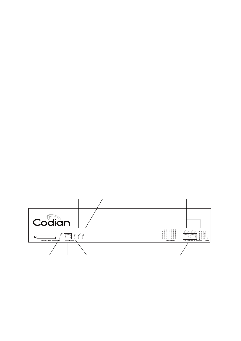
Figure 1 shows the position of ports and LEDs on the MCU.
Figure 1: MCU front panel
Compact Flash
Activity LED
Status LED
Console Port
Alarm LED
Console
Link LED
System Load LEDs
Ethernet Ports
Ethernet Port
Status LEDs
MCU 4510
High Definition
Power LED
1
Page 6

LED behavior
Table 1 describes the behavior of the LEDs.
Table 1: MCU LED behavior
LED Color Indicates
Compact Flash Activity Flashing
green
One of:
the MCU is booting
a configuration change has been made
the configuration is being transferred
by FTP
Console Link Green A PC is connected to the console port
Status Green The MCU is operating normally
Alarm Red The MCU is booting or has developed a
fault, for example:
temperature is outside normal limits
fan failure
battery failure of the internal clock
Refer to the web interface for more
information about the problem (go to
Status > Health)
System Load Green The MCU is processing conference data.
The LEDs represent the media processing
load of the MCU. The column numbered
1 represents audio load. The other
columns represent video DSP load. Media
processing load is also displayed in the web
interface: go to
Status > General
2
Page 7

Table 1: MCU LED behavior (continued)
LED Color Indicates
Ethernet Port Status, for each
Ethernet port :
FDX Green The link has been negotiated as a full-
duplex link
Act Green Packets are being transmitted on this port
Link Green The speed of the link from this port,
which is either 10, 100, or 1000 Mbps
Power Blue The MCU is receiving power
LED behavior
3
Page 8

Connecting the MCU
Before you start
IMPORTANT: Before installing the MCU, you must read the safety
information at http://www.codian.com/safety.htm
Step one: Connect power
Connect the power connector on the rear of the unit to the power supply using the
supplied power cable. (There is no On/Off switch.)
Step two: Connect to Ethernet Port A
Connect an Ethernet cable from Ethernet Port A to an Ethernet switch (rather than a
hub, to minimize interference from other devices on the network). The Ethernet
port is a 10/100/1000 Mbps auto-sensing connection
Only connect to Ethernet Port B if you need to connect the MCU to a
i
second subnet.
Do not connect Ethernet Port A and Ethernet Port B to the same subnet.
!
4
Page 9

Initial configuration
Initial configuration
Step one: Connect to the console port
1 Ensure power is connected to the MCU and the Status LED is green. 2 Connect the console port of the MCU to the serial port of your PC using the
blue RJ45 to DB9 cable supplied.
3 Use a serial terminal program, such as Secure CRT or HyperTerminal, to
connect to the MCU. Set your terminal software to the following settings:
Baud rate: 38400
Data bits: 8
Parity: none
Stop bits: 1
Flow control: none
4 Press Enter and the following command prompt appears on the terminal:
MCU:>
Step two: Configure Ethernet Port A settings
The default setting for the MCU Ethernet ports is auto-sensing mode. If the switch
ports to which you connect the MCU are not also set to auto-sensing mode, then you
need to configure the MCU Ethernet ports to use the same speed and duplex mode.
Only connect to Ethernet Port B if you need to connect the MCU to a
i
second subnet.
Both ends of the Ethernet connection must be configured in the same
i
way. For example, either configure both ends of the link to be autosensing or configure both ends to operate at the same speed and duplex.
To establish a 1000Mbps connection, both ends of the link must be
i
configured as auto-sensing.
5
Page 10

To configure Ethernet Port A, enter the following for auto-sensing mode:
ethertype auto
or to configure a speed and duplex, use the following command:
ethertype <10|100> <half|full>
To display the current configuration and status of the Ethernet ports, enter:
status
For example, to configure a full-duplex 100Mbps link, enter:
ethertype 100 full
To establish a 1000Mbps connection, both ends of the link must be
i
configured as auto-sensing.
Step three: Assign an IP address to the MCU (optional)
The default setting for the MCU is to use DHCP to obtain an IP address. You can
assign a static IP address if you prefer or if a DHCP server is not available.
If you want the IP address of the MCU to be assigned by your DHCP server, omit this
step.
To assign a static IP address, use the following command:
static <IP address> <netmask> <default gateway address>
<DNS server address>
If you do not have a DNS server, use 0.0.0.0 as the DNS server IP
i
address.
For example, to assign an address of 192.168.1.2 where the default gateway is at
192.168.1.1, enter:
static 192.168.1.2 255.255.255.0 192.168.1.1 0.0.0.0
To return to using DHCP after setting a static address, use the following
command:
dhcp
Step four: Discover the IP address of the MCU
1 To display the current status of the IP address, enter: status
If you have DHCP enabled on your network and you are allowing the MCU to
acquire its address using DHCP, the IP address that has been acquired by
Ethernet Port A will be shown; if you have assigned a static IP address, that is the
address that will be shown.
2 Make a note of the IP address. You will use this to access the web interface of the
unit.
6
Page 11

Configuring the MCU
Configuring the MCU
Step one: Log in to the MCU
All administration of the MCU is performed via the web interface.
To log in to the web interface of the MCU:
1 Use your browser to navigate to the IP address of the MCU (to discover the IP
address, refer to the previous section).
2Click the
and enter the user name
i
Step two: Using an H.323 gatekeeper or SIP registrar (optional)
If you have H.323 endpoints, using an H.323 gatekeeper can make it easier for
participants to call in to a conference. You can configure the MCU to use an external
gatekeeper or its own built-in gatekeeper. For information about using the built-in
gatekeeper, refer to the online help.
Log in link on the top right of the screen, then click Change log in
admin with no password.
Codian recommends that you change the admin account to use a
password as soon as possible. To do that, go to
Users, click the admin
link, and provide the required user information.
If you have SIP endpoints, using a SIP registrar can make it easier for participants to
call in to a conference.
To configure the MCU to use an H.323 gatekeeper:
1 In the web interface of the MCU, go to
2Enable
H.323 gatekeeper usage and configure the settings you require, using
Settings > Gatekeeper.
the online help for further assistance.
3Click
Apply changes.
To configure the MCU to use a SIP registrar:
1 In the web interface, go to
Settings > SIP.
2 Configure the settings you require, using the online help for further assistance. 3Click
Apply changes.
Before you configure the MCU to use, and register conferences to, a SIP
i
registrar, you must set up the MCU and its conferences on that SIP
registrar.
7
Page 12

Step three: Add endpoints (optional)
One way to add participants to a conference that you create is to have the MCU
automatically call them when the conference starts. To do this, you configure their
endpoints on the MCU. When you set up a conference, you can choose the
endpoints from the
each endpoint’s details every time. Participants that are pre-configured for a
conference will automatically be called by the MCU to join that conference.
To define pre-configured endpoints:
1 In the web interface of the MCU, go to
To add a H.323 endpoint, click Add H.323
To add a SIP endpoint, click Add SIP
To add a VNC screen, click Add VNC
2 Configure the endpoint settings you require, using the online help for further
assistance.
3Click
Add endpoint.
Pre-configured participants list. This is easier than entering
Endpoints:
8
Page 13

Using the MCU
Using the MCU
Creating conferences
To create a conference:
1 In the web interface of the MCU, go to
conference
2Type a
.
Name for the conference, for example SalesMeeting.
3 Type an optional numeric identifier, for example
telephone number that participants can use to join the conference when calling
in to the MCU via a gatekeeper or SIP registrar.
There are two types of conference participant: chairperson and guest.
i
IDs and PINs allow participants to connect to conferences as the correct
participant type. Chairperson participants use the Numeric ID and
optionally, the PIN; guest participants use the Guest numeric ID and
optionally, the Guest PIN. For more information, refer to the online help.
Conferences and click Add new
123. This will be the
4 If you are using a gatekeeper, check
registrar, check
5 Ensure the
SIP registrar.
Maximum duration of the conference is sufficient (the default is one
H.323 gatekeeper; if you are using a SIP
hour).
6 All other values can be left at their default settings. Refer to the online help for
further information about the available settings.
Note that if you do not configure the conference to start immediately, it
i
will become a scheduled conference and will be inactive until its start
time.
7 Scroll down and click
Add conference.
The conference you have created is now active (if you used the default immediate
start time) and participants can join in one of two ways: either the MCU can call out
to specified endpoints or endpoints can dial in. Any endpoints that have been added
to a conference, as pre-configured participants, will be called in to the conference by
the MCU.
9
Page 14

Calling participants in to a conference
To call participants in to a conference:
1 In the web interface of the MCU, go to
Conferences and click on the name of an
active conference.
2On the
Participants tab, click Add participant to call out to an H.323 or SIP
endpoint.
3In the
Address field:
where there is no H.323 gatekeeper or SIP registrar, type the IP address,
host name, or SIP URI of an accessible endpoint on your network
if you are using an H.323 gatekeeper, enter the number registered with the
gatekeeper for the required endpoint
if you are using a SIP registrar, enter the number registered with the SIP
registrar for the required endpoint
4 Leave the other fields as their default values and click
Call endpoint. The MCU
automatically connects to the endpoint.
5 If the endpoint is not configured to automatically answer calls, accept the call on
the endpoint.
Calling in to a conference
Participants can call in to conferences in either one of two ways:
if you have given the conference a numeric identifier and you are using an H.323
gatekeeper or SIP registrar, tell participants to dial the numeric identifier from
their endpoint to join that conference
participants can dial the IP address of the MCU to access the auto attendant of
the MCU. Participants will see a menu of available conferences on their video
screen and will hear instructions
10
Page 15

Using the MCU
Streaming conferences
Streaming is a way of viewing a conference in a standard web browser. The MCU
allows streaming of video and, if enabled for a conference, the streaming of data. You
can also conduct a text ‘chat’ and add notes and drawings to the data stream.
Note that to use the ‘chat’ facility when streaming a conference, your
i
MCU needs the web conferencing feature key. For more information,
refer to your reseller.
You can configure two streaming options on the MCU that will be available for users
to choose between when streaming conferences. For each streaming option, you
must choose a media player (QuickTime, RealPlayer, or Windows Media Player) and
a bit rate.
To configure streaming options:
1 In the web interface of the MCU, go to
Settings > Streaming.
2 Configure the streaming options you require, referring to the online help for
more details about options.
3Click
Apply changes.
Streaming users will need to have installed one of the media players that you have
chosen for the two streaming options. Streaming users might also need to install Java
(from www.java.com).
To stream a conference:
1 In a web browser, go to the IP address of the MCU (or if you are already logged
in, go to
2Type in a
and the
3Click
Home and click Streaming-only interface).
Sign-in name (the name by which you will be identified if you ‘chat’)
Conference ID (the numeric identifier of the conference).
Stream this conference and streaming will start.
11
Page 16

Instructing conference participants
You need to tell conference participants how to join conferences. You can also tell
them how to use the Far-End Camera Controls (FECC) to navigate menus in the auto
attendant and choose conference layouts. There is a document: Getting Started:
Accessing Conferences available in the documentation area of the web site, which you
can print out and give to conference participants.
Checking for updates
It is a good idea to regularly check for updates to the main MCU software image.
This section describes how to upgrade the MCU using the web. Note that you can
also upgrade the MCU using FTP; this can be more reliable if you are upgrading the
device remotely. Upgrading your device via FTP is described in the release notes that
are available alongside the software images in the support section of the web site.
To check for, and download, updates:
1 Log in to the MCU web interface and go to
2 Make a note of the software version that is currently installed.
3 Go to the support section of the web site and check if a more recent release is
available for the MCU.
4 If a more recent release is available, download it and save it locally.
To upgrade the MCU:
Status > General.
1 Unzip the software release file that you downloaded. 2 In the MCU web interface, go to 3In the 4Click
Main software image section, click Browse and locate the unzipped file.
Upload software image. The browser begins uploading the file to the
Settings > Upgrade.
MCU, and a new browser window opens to indicate the progress of the upload.
When finished, the browser window refreshes and indicates that the software
upgrade is complete.
5Go to
Settings > Shutdown to shut down and restart the MCU.
Note that shutting down the MCU will disconnect all participants.
i
12
Page 17

Troubleshooting and technical support information
Troubleshooting and technical support information
Using the event log to help solve a problem
Unless you are experiencing a problem, all event logging sources should be set to the
default, which is
configuring the event log, refer to the online help accessible from the web interface.
You can use the event log to produce debugging information to assist technical
support in solving your problem. However, we recommend that you only alter the
setting of the event log under the guidance of technical support. In particular, you
should not turn on event logging sources without good cause or advice from
technical support.
Getting more help
If the documentation does not answer your question or you have a problem with one
of our products:
1 Refer to the Technical FAQ section of the web site. We keep the Technical FAQ
section up to date with the latest information from our technical support team
regarding the resolution of customer issues.
2 Contact your reseller. Our resellers have a wealth of experience with our
products and this is often a quick way of solving a problem.
3 If your query remains unsolved, there is a web form in the support area of the
web site that you can complete. Ensure that you provide all the details requested
by the form to assist the technical support team in resolving your problem:
the serial number and product model number (for example: MCU4510) of
the unit
the software build number (to find this, in the web interface, go to Status >
General
where you purchased the unit
your contact email address or telephone number
Errors, warnings and information. For more information about
)
13
Page 18

Technical specifications
Power requirements
Table 2: MCU ratings
Rating Value
Nominal voltage 115V to 230V 50/60 Hz
Current rating 6A Maximum
Supply voltage range 100 to 240V 50/60 Hz
Over-current protection
Ensure the supply to this unit is protected by a branch circuit protector rated by a
maximum of 20A.
Caution — over-current devices must meet applicable national and local
!
electrical safety codes and be approved for the intended application.
Operating environment
The MCU must only be used within the following environmental conditions:
Table 3: Operating environment
Environment Temperature Humidity
Operating environment 0°C to 35°C 10% to 95%
(non-condensing)
Non-operating environment -10°C to 60°C 10% to 95%
(non-condensing)
Optimum operating environment 21°C to 23°C 45% to 50%
(non condensing)
Anti-static precautions
When servicing or removing components or connections, first attach an anti-static
wrist strap to an appropriate earth point.
14
Page 19

61-0011-05
 Loading...