

Page 1
January 1967
TANDBERG
Models 64x
The models 64x
the earlier models
tion is
64:-62.
electrical adjustments necessary for
62x.
The models
facilities
an appendix to
lt
as 64-62. A new,
and
64-62
covers the special
64x and
are improved versions
62x
and this
the
62x
service
have the
alignment instruc-
manual
head alignments
and
separate
TAPE.RECORDER
Alignment
heads
and
Preface
for
model
model
same operation
64x
bias head
instruction
for
electronics
of has been introduced
and torized. Certain minor
and
and 62x
to improve the frequency
the
is
operated
ratio.
fully transis-
and
introduced
further introduced
is
1.7/e i.
in
bias
automatically
sponse and the signal
The
oscillator has
in the equalization circuits, mainly changes
ponent
in
tape speed. This switch
the
bias
the
speed
values. A
circuit
selector
to noise
been redesigned
changes have been
microswitch
to
reduce
mechanism. See fig. 3.
re-
of com-
p.s.
by
TANDBERGS
Ti.^d.{*..q
r=r=rErlEr/
RADIOFABRIKK
A/S
OSLO
NORWAY
Page 2
1.0 Alignment
It
is important that
the
heads
this
recorder
tape
sponse and
1.0.1 Demagnetizing
Demagnetize
aligning
on
contact the
5-10 times at normal speed
polished
the signal
the heads.
the
the tape
tape should be run through the
before measuring
the heads and adjacent
contact
recorder is
to noise
between
good.
the
ratio.
the
tape and
To
obtain
to have the
frequency
parts
before
tape
re-
tape speed.
corresponding
the height of the
is
botained on a
Azimuth alignment:
3.1.3
Play back the test tape No.
pre-recorded
speed.
head until maximum reading
output
meters.
The record level of the
to track 3 is
playback
V.T.V.M. from
tape with 10.000
Adjust the
azimuth
head
position
area
exact
reduced
track
2. This is a full track
cls al 71lz i.p.s. tape
is obtained on both
30 dB.
minimum output
until
(ch.
3
of
2).
the
Adjust
playback
1.0.2. The mounling
The
height of the mounting
is
aligned by the adjustment screw
playback
normal forward
the
the
guide
1.0.3
Set the
tape
the
equidistant
guide.
2.O Adjustment of
circuits.
2.0.1 Insert
bias head half to
across each
2.O.2
tion while R607 and R610 are
o'clock. Rel. fig.
2.0.3 Set
the
2.0.4 Use a
meter or
adjust the oscillator
=
2.0.5 Set the
and
2.0.6
F/osc.
2.0.7
2.0.8 Readjust L
osc.
CH 1, CH 2 and stereo
The deviation should be indicated
meter, long wave
2.0.9
V.T.V.M.
3.0
Test Tapes,
3.1.
3.1.1 Connect
FOLLOWER
3.1.2 Height
Play back
pre-recorded
head. Move
height of
runs
tape
(79,2).
The adjustable tape
operating lever in
inserted
adjustable tape
from the
Repeat
one
resistor.
R 609 and R 612 is turned up
the
speed selector
calibrated
frequency
kc/s.
85.5
the
speed selector to 7tlz
Adjust
will
then
the
Set
frequency
Adjust
Head
C 602
(between
alignment
Model
playback
The
output.
alignment:
the test tape
plate
lor the heads
plate
for the
the operating lever
with
drive
mounting
the
equidistant
and depress the
guide
1.0.2.
10 ohm resistor
ground
3.
recorder
tape
to
tape recorder
the oscillator
be
85.5 kc/s.
recorder for mono recording CH 2.
tape
to
601
deviation between mono recording
receiver or
and
100 mV and 400 mV).
64x
head
one
tape with
tight
a
from the
guide
flanges
the
7tlu i.p.s.
long wave
counter for the indication
frequency
compromise
should
604
and track
V.T.V.M.
1000
tape
plate
for the heads
flanges of the tape
normal forward
push-button
(79.3)
until
of
the adjustable tape
oscillator and bias head
in series with each
and
connect
set
to stereo recording and
receiver, frequency
by
for mono recording
i.p,s.
frequency with
be less
frequency
to max. reading on the
control
to each
No. 1.
This is
c/s recorded
(15.4)
heads
rear
at the
inserted.
the
a V.T.V.M.
1 o'clock
to
to approx. 11
C 610 until f/osc.
if necessary. The
than 2 kc/s.
with
counter.
with
a full track
atTt/zi.p.s.
the
of
slowly
Align
until
with
drive
lll. Align
runs
tape
posi-
and
CH
L601
frequency
Tandberg
CATHODE
Lateral
3.1.4.
Check
pulling
head when
to
output level
Adjust the
necessary,
adjust the
The
3.2
Adjust
3.2.1
the
until
fig. 1.
Adjust
3.2.2
runs freely
Height
3.2.3
record
The
approx.
upper track is visible
the record
powder
on the
pattern
head is
Azimuth
3.2.4
Connect
CH1 and
FOLLOWER
1
Make a
15.000 c/s
head to
put
level
playback
gain
controls until this is obtained and
azimuth
Lateral
3.2.5
Check the
pulling
head during the recording.
not
decrease
position
the head mounting
azimuth
3.2.4.
The
3.3
Heighl
3.3.1
Connect
heads.
i.p.s.
71 lz
down
alignment:
the
lateral
pressure pad
the
the test
should not decrease more
lateral
by turning the head mounting
azimuth
record
head is in
0.1 mm
method
tape
on the tape will
correct.
a signal
stereo
max. reading
volume controls
position
the
of the record head, if necessary, by turning
position
Set
to
0.
head.
the horizontal
the height
in the
alignment:
head is
head can
(Magna-See).
and dip the tape in the solution. The
Readjust
alignment:
and
CH2,
outputs
recording in
signal.
should now be approx. 100 mV with the
alignment:
lateral
pressure pad
more
head.
bias
alignment:
V.T.V.M.
two
the tape recorder to
and turn both
position
position
position.
groove
set
(.0025")
generator
Adjust
of the record head.
position
of
of
(59.5)
No.
tape
of
position
center of the record head. Ref.
the
of
in front
preliminary position
in a
of
above the tape. The
inspected
be
show il the
if necessary.
V.T.V.M.
two
and
CH1
the azimuth of the record
the
on
to max.,
(59.5)
than 3
plate.
the head. Ref.
directly across the
playback
playback
the
from
away
played
2 is
playback
the
of the bias
bias head until
of the
lamination for the
the
by using the iron
Record all
to the HI-LEVEL inputs
to
CH2.
B-test al 7t/z i.p.s. of
readjust
away
Adjust the
dB.
stereo
meters.
record head
para.
volume controls
output
of the
The output level should
Recheck the height and
head by
the erase
back.
than 3 dB.
head, is
plate.
the
bias
head.
position
four tracks
position
the
CATHODE
The out-
the record
check
from
the erase
3.2.3 and
recording
recording at
The
Re-
head
tape
where
of
of the
a
the
by
lateral
Page 3
Adjust the height of
adjustment screw
obtained
freely in the
that
head and
The height
and
mounting
raise
3.3.2
Connect two V.T.V.M.
outputs, and
LEVEL inputs
to
back volume controls
Record
Untighten the
(ref.
Ieft
reading
should now
controls until this is
tal
that the
tighten the
the head is
indicated
A fine-adjustment
the
R
609 and R
meters
3.4 The
3.4.1
The erase head is
approx.
upper track
tape. Insert
signal from the
cording level. Dip
and
of
does
3.4.2 Azimuth
Align the
azimuth adjustment
parallel
The
3.4.3 Lateral
Turn the
the front
3.5 Model
All
and
paragraph
paragraph
4.0
with
4.1
Play
recorded
on
both
groove
is
there
if
the clearance between
the bias head slightly.
Horizontal
stereo recording al 71lz i.p.s.
fig.
position
position
pot.meters
Height adjustment:
check that the re-recorded
the
not
azimuth
the
3'4 are valid for
control
Tandberg
Control of
back the test
sufficient
the
mounting
position
plate
alignment:
connect a signal
CHI and CH2.
a 1000
is
are obtained.
erased track. Make
with the
alignments
c/s
fixing
'1)
move the
and
towards
obtained
be approx..5V,
the
of
horizontal
adjustment
not being moved.
by a loss
R609
612 until max. reading
erase head.
0.25 mm
of
the test tape No.
erase any
alignment:
azimuth
position
alignmenl:
head mounting
the
of
62x.
3.1.2 which
3.2.3 is
and adiustment
test tapes.
tape with the
the
(ref.
fig.
V.T.V.M.
in front
clearance between the bias
plate
the
of
for the record
to both
to max.
signal.
screw
bias head from the
the recording head
on both
obtained and check
bias head. After
position
of the output level.
the
of
bias current is
(CH1)
in
set
a
(.01")
of
the
erase head is visible
generator
tape in
the
part
of
position
screw. The
mounting
of the erase head is not
plate
head is
the
parallel
specified
model 62x with
is
superseeded by 6.6.2.
playback
tape No.
following frequencies:250-
bias head
1) until max. reading is
Check
of
for
bias head is not
the bias head and the
CATHODE
Set
for
horizontal adjustment
V.T.V.M. The output level
readjust
is
screw making
and
preliminary position
the
9 and
on
ch. 2 at maximum re-
the Magna-See
sure that the
the adjacent tracks.
of the
erase head
plate
for the
in chapters
superseeded by 6.1.1
ol
amplifier:
This
3.
by the
that
the
the
bias head and
the record head.
head is
generator
the
tape recorder
turn
and
the record
one has assured
correctly
This is eventually
(CH2).
R612
on
ferrite core for the
record
track lies
erase head by the
for the
erase head, until
pressure pad.
to the
the exception-o1
playback
is
a full track
height
tape
critical,
insufficient,
FOLLOWER
to the Hlboth
extreme
until
the
horizon-
adjusted,
sure that
obtained by
Adjust
the optput
where
above the
a 1000
solution
in
center
erase head
should
heads
(15.4).
critical.
3.1, 3.2, 3.3,
amplifiers,
runs
play-
max.
gain
c/s
be
and
pre-
10
000- 5000 - 1C00 - 100i.p.s. tape
standards. The
frequencies.
channels
4.2
Play
controls
tape
potentiometers
reading
5.0 Adjustment of
the
Make
and 3.0 are made before
justments.
Connect a
and two V.T.V.M.
puts.
Record
playback
the record levels
the output
lV and V
by
R115
the output meters
on
Adjust
tronic
buttons lV
readings
6.0 Head alignment
6.1 The
6.1.1 Height
The
height adjustment
shall
channel
6.1.2 Azimuth
Play
V.T.V.M.
Adjust the
azimuth
obtained on the output
6.1.3 Lateral
Pull
when
played
more
playback
mounting
6.2
iorro*'in"l
6.3
Follow
6.4 The erase
6.4.1 Height
The
adjustment
speed. The tape
output tolerance is
The
difference in
should be less than 3 dB.
Adjustment
the test
back
to maximum. This is
with 400 c/s
R233
on the
electronic
sure
a 4O0
R 137
beam indicators
height
run flush with
back a standard
the
the
back. The
than 3 dB. Adjust
The
The
the instructions
height
output meters
beam indicators.
that
all adjustments
signai
cls signal in
volume
levels
(stereo
1.
connected to
adjustment
pressure
B-test) and
(CHl)
and
(CHl)
and V
still are 1.5 V on
playback
alignnnent:
of the
alignmenl:
position
alignment:
standard azimuth alignment
head, if
plate.
record
instructions
bias head.
head.
alignment:
of the erase
screws. Approx.0.25
playback
of the
tape No. 4 with
at71/z i.p.s. tape speed.
(CH
the record
generator
to both
controls to max. at 7tlz i.p.s. Adjust
by the record
1.5 V. Depress
are
R116
are 1.5 V.
and R 138
are
(stereo
without Tandberg
head.
playback
screws. The upper edge
the
azimuth
each cathode follower
of
screw,
meters.
pad
(59.5)
output
necessary,
bead.
given
given
head is
50-250 c/s
conforms
a full track
1)
and
are 1.3V.
proceeding
to
CATHODE
stereo A-test, with both
adjust
(CH2)
closing.
A-test)
the output
head is
upper
playback
the
until
away from the
level
lateral
the
under
under
recorded
with the N.A.B.
-+
2
dB
level
between the
amplifiers:
the output
prerecorded
Ad.just the
(CH
R234
current
under
both Hl-LEVEL
gain
the
until the readings
(CH2)
Release the
and
part
alignment tape with a
maximum
should not
by turning
aligned by
2)
(A-B
paras
with these ad-
FOLLOWER
controls
push-buttons
the
record current
until the elec-
check
meters.
Test Tapes.
aligned by the
of
of the airgap
head by the
reading is
erase head
tape is
position
para3.z.
para
3'3'
the height
(.01
mm
at71/t
for
all
two
volume
the
until
test) and
1.0,
2.0
inputs
out-
until
push-
that the
the tape
for
output.
being
decrease
the
of
the head
")
of the
Page 4

/z
'1
.B.
all
WO
me
ed
ihe
:he
nd
2.0
rd-
uIs
ut-
)th
ust
ntil
,ns
ent
lgs
ecshthe
the
tpe
for
1a
)ut.
the
tis
nd
ing
lse
the
nd
lht
lhe
ferrite
should
6.4.2 Azimuth
Align
azimuth adjustment
parallel
be
(15.4).
critical.
6.4.3 Lateral alignment:
Turn
the
the front
6.5 Track control, model
6.5.1 The record head:
Record a 1000
cording level in
buttons
Turn
the tape
on
track 4 and 2. Cut the tape and
of iron
recording visible. The
tracks
tape. Readjust
recheck the azimuth alignment.
6.5.2 The erase
Insert a full-track
1000
c/s signal from
ing level in mono
lll
and
Magne-See
is in the center
pos.
of the
6.5.3 The
Record a 1000
c/s
signal on track 3
levels. Turn the tape
(push-buttons
lume.
head if the
back head if the
the
azimuth
Track
6.6
The
6.6.1
The height
adjustment
from the upper
The
6.6.2
The height
adjustment
(push-buttons
recording level
the tape in the Magne-See
the tracks
tape, and that
center
the record heads, if necessary.
6.6.3
The height
height
for the upper track
core
visible above the tape.
be
alignment:
the azimuth
The azimuth
head mounting
of the head is
l,
ll and lll
powder
should be distributed
depressed). Cut the tape
erase
playback
No
signal should
erase head:
of
record
of
the
of
playback
The
adjustment screws. The
position
with
the mounting
position
from a
c/s
stereo A-test on track 1 and 3
depressed)
around and
and alcohol
height
the
head:
pre-recorded
A-test on
solution. Check that the
of the erased area. Adjust the
head
head:
c/s signal
lll and V depressed) at
1000 c/s signal is heard. Lower the
500 c/s
position.
control,
the erase
screws.
the lower
and
head:
the record head is aligned by
screws.
are distributed
of the
Record a 1000
l, ll
and
on a
the recorded
erased
head:
playback
of the
screw.
a
model
The
full-track
The erase head
of
plate
forthe
parallel
64x.
generator
make a similar recording
(Magne-See)
spaces
position,
generator
track
necessary.
if
on track
(CH2)
at maximum recording
around and
heard. Raise the
be
signal
62x.
is
head
tape
lll
depressed) at maximum
solution
symmetrically
zone. Readjust
head is
the erase
of
head by the
erase
plate
for the heads
erase
the
erase
to
the
at maximum re-
for
approx. 5 seconds.
it in a mixture
dip
between the
equidistant
necessary, and
if
tape
and
at maximum record-
(push-buttons
3
and
re-recorded
(CH1)
1
play
is heard.
aligned by the height
run equidistant
shall
edge of the
c/s signal
pre-recorded
and
remains
zone
the erase
aligned by
tape
shall
should
head is not
head, until
pressure pad.
(push-
make
to
recorded
across the
record a
dip it in the
vertical
and a 500
back
track
maximum
playback
Re-check
ferrite core.
height
the
in
stereo
tape. Dip
check
across the
in the
run
head
the
track
vo-
play-
that
and
the
flush
with
the upper edge of the lamination
Readjust
the azimuth in
7.0 Adiustments
Test
Tapes.
A V.T.V.M.
signal
is connected
generator
is connected to the high level
of both channels and
The
tape recorder is
(push-buttons
ing
lever in normal fonvard
tape
speed. Insert
Adjust the
the
on
controls
output
to
ll,
l.
recording
meters are 1.5V with
maximum.
Replace the V.T.V.M.
meter and depress the
Adjust
ing
Replace
meter
Adjust
ing
Adjust
nic beam
the recording
shows
o/o
3
V.T.V.M.
the
distortion.
and depress the
the recorder current by R 116
shows
o/o
3
R 137
distortion.
(CH1)
indicators are closing.
Connect a V.T.V.M. to
necessary.
the amplifiers,
of
to each output terminal. The
tuned
up
set
lll
and
good quality
a
gain
for channel 1 with a distortion
push-button
current
for channel 2
push-button
and R 138
each
ceed the recording as described
test
with all
Adjust the R
reading on
ll
that
Release the
and check
the
push-buttons
(CH1)
233
the output
playback
volume
push-buttons
the reading
that
meters
are 1.5 V.
8.0 Control of total frequency
The tape
(all
and with
2
(Scotch
fore
A V.T.V.M. is
signal
of
set the
below
output
the frequency
the
7t/zi.p.s.:
33L
17la
The
should
recorder is set up for
push-buttons
150
use to
generator
depressed) at7llz
good quality
a
which
have
should be
the tape
connected
is connected to the Hl-level inputs
to
both channels. Tune the
output
maximum
level from
recording
meters are the 0 dB reference
response
for all speeds according
specification. Ref. fig. 7.
level
dB
(-.t(-+Z
(-+Z
at
20-25 000 c/s
i.p.s.: 20-18 000 c/s
i.p.s.:
dilference
be
000 c/s
30-12
in
less than 3
Increase the bias slightly
high. Adjust R
and
Adjust R
33L
i.p.s.
607
(CH1)
609
(CH1)
and R
and R 610
correct frequency response
8.1 Control of
lf
the frequency
playback
response
for
channel 1.
vuithout Tandberg
inputs
to 400 c/s.
for
stereo
depressed
drive
with
position)
recording
controls
until
lV
by R
115 until
with the
(CH2)
until the electro-
recording
the
(B-test
(B-test
V
until
operat-
the
at 7tlz
tape.
readings
the
playback
the readdistortion
the read-
A-test
CH1).
CH2).
output terminal and
in
above
stereo B-
depressed.
and R 234
(CH2)
until the
are 1.5V. Make
controls are
lV
on
V
and
output meters still
the
to max.
set
(stereo
A-test)
response.
recording B-test
stereo
recording
run
surface
polished.)
each output
generator
generator
the
i.p.s. tape
tape
5-10 times be-
to 400 c/s and
speed,
inserted.
terminal. The
30 dB
level. The readings on the
points.
2
30-20
dB
aA 30-15
Og 40-
between
frequency.
any
if
the treble response is too
612
(CH2)
is
obtained.
record
and
does
000 c/s)
000 c/s)
I000 c/s)
the two channels
(CH2)
for
amplifiers.
not
stand up to
Check
forTt/zi.p.s.
i.p.s
77la
i.p.s.
pro-
sure
to
until
the
Page 5

lor
channel 1.
Tandberg
rcul
rterminal. The
inputs
level
3h
rcording A-test
ith
operat-
the
on) at 7tlu
i.p.s.
ding tape.
il the readings
playback
the
ith a distortion
(B-test
/
CHl).
until the read-
the
h
distortion
(B-test
/
until
ntil
rminal
tve in
(CH2)
.5 V.
are set to
(stereo
rtput meters
CH2).
read-
the
the electro-
pro-
and
stereo B-
until
Make
sure
max.
A-test)
still
the
tolerances
back
8.1.1
Insert
head for
Connect
press
set the
playback
the
generator
2
mV. The
reference
frequency
Repeat
The
The
should
8.'1.2 The
Insert a
head for
Connect
generator
Depress
and
set the
Tune the
output
recording
the
0 dB reference
ponse
given
and
record
playback
The
100
a
the upper
a signal
push-button
the
operating
is
point,
response
the measurements
oulput
difference
be maximum
record
1000
upper
a V.T.V.M.
is
the
signal
from
level.
according
above, one
amplifiers.
amplifier:
ohm resistor
track
generator
lV
lever
volume
tuned
reading
control to
to
400 c/s with
on the
at 7tlz i.p.s. tape
according to
tolerance
is
in level
3 dB at
amplifier.
ohm
resistor in
(CHl)
track
across the
connected to
push-button
operating
lever
generator
generator
the
The reading
point.
lig.
to
should check
in
series with
(CH1)
ground
to
across the resistor.
(monaural
to normal
plaback
forward
maximum.
an
output level
output
meter is
speed.
fig.
6.
for the lower
-+2
between
dB
for
all
the two
any frequency.
series
with the
ground
to
resistor. The
the Hl-level
(monaural
|
to
to 400
recording
normal forward
c/s
30 dB below
on the
Check
output
the frequency
5.
play-
the
playback
the
(red
wire).
De-
CH1)
and
drive with
The
signal
the
0 dB
Check the
(CH2).
track
frequencies.
channels
record
(black
wire).
signal
input
of
CH1.
CH1)
drive.
and
set
the
maximum
meter is
res-
Repeat
The
output tblerance
The
ditference
should
9.0 Adjustment
Feed
a 19 000
depress the
switch to
to
of
maximum.
to
set
maximum
to
each
(CH1)
L4
output
10.0
Adiustment
The
bias is
correct
(Ret.
fig. 2
circuits
and R
610
microswitches
der, ref.
Set the
two
screws holding
the bracket
the
switches
Check the.
knob
slowly
switches
the
measurements
in level
be less than
ol the FM-muttiptex
c/s
push-buttons
A-B test
The recording
recording level.
cathode
and L5
follower
(CH2)
meters.
ot the microswitches.
reduced
frequency
and 4) is
and
activate
(CH2)
in
are
fig.
4.
speed
selector
slowly towards
operate
adjustment
lrom
shall now
for
the
-+2
is
dB
for
between the
at
3 dB
signal to
any trequency.
both FM-MX inputs
I and ll.
and the
playback
gain
Connect
output.
for minimum
in
17e i.p.s.
response.
introduced
the
17/e
located
to 17e
tape
The microswitches
in the
potentiometers
i.p.s.
tape
at the
i.p.s.
the microswitch
the
activating
and tighten
by moving
17/e
to 33/+ i.p.s.
operate
properly.
lower
track
all frequencies.
two
channels
titter.
Set the
volume
controls
S-on-S
controls
should be
a V.T.V.M.
Adjust the
reading
speed
bias
speed
rear
core
on
to
regulating
R
607
onty.
of the recor-
and loosen
bracket. More
arm until
the
two
screws.
the speed
selector
and back.
(CH2).
and
of
the
obtain
(CH1)
The
the
The
)n8e.
recording
,p.s.
tape
I
5-10
tape
inserted.
times
B-test
speed,
be-
ished.)
rut
terminal.
Hl-level
r
r to
400 c/s
Inerator
readings
points.
e
The
inputs
and
30
dB
on the
Check
ds according
20
000 c/s)
15
000 c/s)
c/s)
9 000
r two
channels
ency.
response is too
iH2)
for
7t/zi.p.s.
or 7?e i.p.s
until
ed.
to
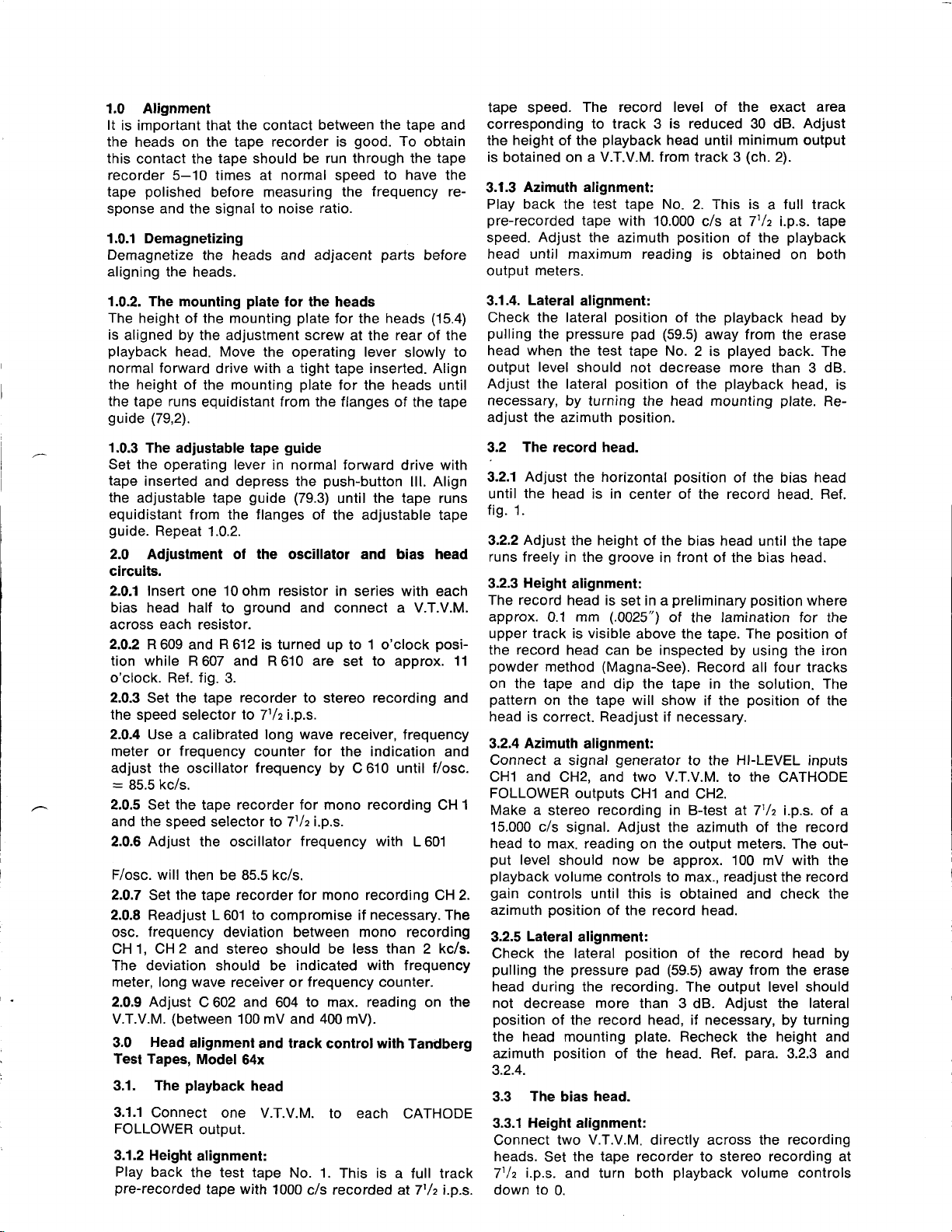
ERASE
HEAD
FIXING
HORIZONTAL
SCREW FOR
AOJ.
RECORD
HEAD
HEIGH T ADJ.
PLAY
HEAD
BACK
SCREW
amplifiers.
stand up to the
Fig. 1.
The
tape
path,
with
location
of the
bias head.
Page 6

HIGX TEVEL
IN PI,JT
UPPER TRACX
(rrFT
LOV{
HIGH LEVEL
PI.JT
IN
LOIVER TRACX
(RIGHT
row tEtEt
To.SorS" SwlTcH
(DEC1fi
CoNT.',t)
cH)
LEVELI
CH)
!
i
| ,!oi5 |
MICROPHONE
\
\/
Mlc.1
/
ITE-con-o+vT
BOARO
N0.5010
18,1
R10:
't0
K
I
Rlo5
R101
5,1 M
*
RlOT
O,1M
125V
r*
2t(
ltY
't25V
ulE
ECC 83/124'
(7025)
Rlll
c101
25, 2t(
Rl12
2t
ECCsy|2AxT
(7@s)
R115
0,1M
cr05
4@0
Rn5
0,ly
S3/t
'tt/c
i.gs.
UPPER
atl
lti-p.s.
1
EOIIaLIZATION
SWITCH Nq50l6
Rl38
o5M
PLA YBAC
HEAD
TYPE
]7H
c1(c4) 25
R 30(R31)39X
R
34(R35)
=---------)
I{ATIVE INPUTS
FM
WII}I
INPUTS HIGH LEIEL.
BOIH
DIN-CONNECTOR
RESP. 4.
c0 Nr. l
K
&X
STEREO
RADIO
l--n-rva.:iiF----EcE6'3^-2AiAo0-2t-l
;
I No 5006
"PifR
|
1c,2
I
IT
7h l'/t
FIIIERS,
ios.
3T
tr
t?
CHANNET
CENTER
.;ff,{-
.iY'"qq!'!"
:l::l
!t'*.,61a,
EOUALIZATION
R
R?0?
oltr
'*'{-Jn-rr-EF
SWIEH
cn0
x
206
O,0/27
tnK
1W
1
NO.5Ol5
a@0anAu1
R2
IM
R 24r
n
t
/3 ip.s
3lt
+
NOTES:
RE5IsIORs INDICATED
x=1000oHMs.
=
1.000.000 0HMS.
|4
* - DEPOSITE0 CARBON
t1O
RES|STORS
3o4=coNf€cTloN
CAPACITORS I
UN LESS OTHER\TVISE SPECI
capAclroRs I zo Z uNLEss
ALL SWIICHES IN NETJTRAL
ALL VOLTAGES MEASUREO AT
LINE VOLTAGE 1IO VOLTS.
RESISTANCE
RESIS]ANCE lN
RESISTANCE lN
RESsTANCE lN L2 AND L3 co. 20 OHMS.
RESETANCE lN L4 Al{0 l-5 co.
z UNLESS
NOICA]ED
lN
6BX
R 212
e8(
5rK
R
238
IN OHMS
RESIST0RS.
OTHERwIsE SPEC|FIED.
PoINTS
MCRd'IICROFARAOS
IN
FI ED,
otneRwrSE sPEcrFrEo
POsITION.
HEAD:
ERASE
RECORD HEAo:
PLAaACX
HEAD, co.250 oHMS.
90 oHMS.
co.
co.300
80
-'l
,tl
0HM5,
ofiMs.
I
I
I
I
I
JIJUERSIOE
,5
!il€R ERAS
UFER ERAS
AIAS
UftR
B|AS HEAo
towER
on S:SWICH
TOP
ffiiliut"T'-
34
R€C.AXPI
12
ctr
AMP
REC
2
(]
I
A-TEST
A.T6T2
HE
o
HEAO
35-
-
35-
-
HEAO
32
3t
(DEC
lN P06B
Page 7

c 60{
50-750
c612
0)r
.f...,.
T-86/
ffi
IMK
OSCILLAToR
No 65sg
':;Y
80ARD
T
601
i-
srYrTcH
-:'--J
R 2{1
tEx
lw
R2\2
6.01(
'tw
n233
IM
I
{q5016
-'t
23l
| |
|...........U_l
R101
c40r
0,15M
0,0lrr
607
os"
R606
20x
[;":
?l ?i
ra ta
t9
r??
1k
-3lt
'G...
|
/.
ilrcRo
SWITCH
u
-
,,
;f-Eril=-;;-^'.'*
r1
ad
r.
l!10
l6Lut
.zf\u'
/ilb I
'l-owER
\v"
ucx
i€
ERAS€
luc
I
IF
DIF
HSAD
WP€ 4IH
!9L
rrcR0
AU10MAil
MOIOR
swrTcH
C
PAPST SYI{CHRO}6US
r-62 32
OR:
ENGEr
5030/45
ES
-INE
ilFo
5oc^
I
I
I
I
I
I
swncH.
)
rD
tO.5375
lq5
4X
nll
3Jt
srART,/sroP
Rl4
l.zx 3W
FGTE bTE
(our510E v ler/
r
R
'l
r0o0=rrr?
vti
#"
vlt
O6
EAM
RIGHT
--- ------J
XOIG
250v
itr4-440
5?49
575o
250V
rmToR
SYllo.lRoxol5
iOHFAFSNFOR
MoToR I MOTOR
INqCAToR
"^ffil"
r,ro.2353
311
^/^
ENGEL
|
-'l
st5r0R5,
SPECIFIE0.
,lriER$/rSE
ilcnoMrcRoF^R
RED,
OTHERWISE
IS
PC6rnOil.
'AI
,EA0r co.
co.300
HEAo:
co.250
H€AD:
co.
!3
co
L5
DS
SPECIFIEO,
90 OHYS.
oHMS
0HM5.
20 oHMS.
E0 oHMS
IOWER
UFEi
UffiR
LWER
TO
I
NPUT
REC. AXP
REC
EFAS
ER^*
AIAS
AIAS
HIGH
CH 2
cll
AMP 2
A.TEsT
Esr2
A-r
HEAO
HE
9
HEAD
32
HEAD
3t
LEVEI
34
1
43
1
S SWITCH
.,50N
TOP(DEX 1 )
,Sors
UPPER
REC 1
l'\
=rJ
PCGInON
TRACX
LOWER
REC 2
PUSH SJTTON
CA]HODE
FOLTOWER
PLAYB.
(B-15T)
rrf-_
E frYtzsto"
El4*-
STOP
TRAC(
SIART
AMP
o
ipARE
SWIrcH
I
2
I
2
NO.6615
g
14
lt
-'"
UPPER.TRACX
PrAYE.l
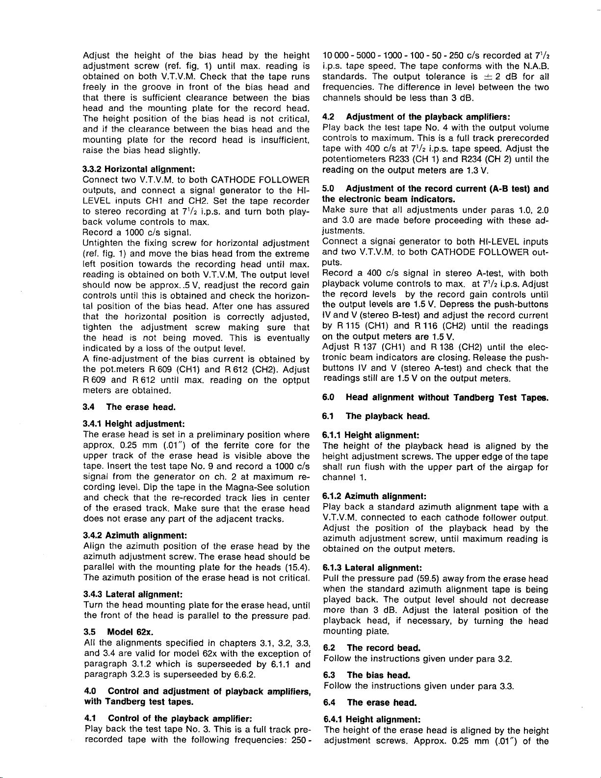
2. Tandberg
Fig.
ToP(oECX
toffRJ.lacx,r"]8?ttE["Ju
SoNS"SWITCH
Tape
NOn004-l
Recorder
2)
TO HIGH
CH?
INPW
TAND*RG
DRAWING
Model
AC50or
tMNSf
Cgqnd
C?,
C5-C6ond
LEYEL
64x
60qA
ro.2?3.
Cll
Cl?
RECORD€R
IAPE
M@EI 64T
N0.6637.
196€
oxl
-
som.con
inlh.
-"-
Schematic'
62x,
H
ilEI
llEI
IFI
)t
\'1
qP
{lrMrEftoo(
H
HHH,"",
Page 8

[ \.\
L0
c6o3
I t
-:
I
h
'%
0
h
q
onrrHSf
'o
(.'(
\e\
\--Y
-
'--r6i'-
0
.lR
0
33
+R6#r
E-,+
l
X{%J
t'
/n
)
l,;-1
R,o
I f
{--t,-_-l [--.C---l ai +
L___j_____J
a
.4-lT1
l,'o'0,lll
L-g ll
c6lrlil
lEllEl Xr
?*-
)H
t-;E;_
r-\_
({{a'
crs
I \ fi;t]
f1__--@1\l/
[Jl
| | ll Jcs,rr)
1,,,,1 ll AV
*u-
.__..-PT
/'^.
H!
-6F
-L-!-q.sr-f
@
{-}
ot61
flcars.\
va
V
-6li-_\/
{@|:l
#
H /A
-\7-
|,;*'f
hG7- 3r
o
*';-f---l
\7
.f]E+
{-rs,:}
ql
-
>()
coo!-35
\9 )
\=_.,,
o
Fig.
The
3.
,fft $ t6 & d r@ &
Fig.
oscillator
5. The response
board, component
curves
for the record
lay out.
r@
90
amplifiers.
Fig. 4. Location
fl@
&Ht$rodsrNd@&
Fig. 6. The
fiers.
response
microswitch
of the
curves for the
for the
playback
bias
circuit.
ampli-
$ ro
Fig. 7. Total
4
r&
@
frequency
& s tm M
response
curves.
 Loading...