

Page 1
Codec
3000
6000
MXP
REFERENCE GUIDE FOR SYSTEM INTEGRATORS
TANDBERG 3000 MXP & 6000 MXP
• Designed for custom integrations
• 19” mountable codecs
• Expandability for future applications
• Total management via serial port, embedded web
server, SNMP, Telnet, XML, HTTP / HTTPS, FTP and
on screen menu
• Best possible call for each MultiSite participant with
rate matching and transcoding
• URI dialling
• H.323, H.320 & SIP support
• TANDBERG E xpressway™ Technology
• Protection against network interruptions in point-
to-point and multipoint calls with automatic
downspeeding and IPLR
• Standards-based embedded encryption
(AES & DES)
REFERENCE
FOR SYSTEM
INTEGRATORS
Software version F7.X
D 13887.08
MAY 2008
Page 2

Finding the Information You Need
We recommend that you check out the
TANDBERG web site regularly for updated
versions of this manual:
http://www.tandberg.com/support/
documentation.php
Thank you for choosing TANDBERG!
The TANDBERG Codec 3000 MXP and Codec 6000 MXP
have been designed to provide you with many years of
safe, reliable operation.
This section of the User Guides contains an overview of
what’s new in this version and the Table of Contents.
Our objective with this Reference User Guide for System
Integrators has been to address your goals and needs.
Please let us know how well we succeeded!
Page 3

Finding the Information You Need
What’s New in This Version?
REFERENCE GUIDE FOR SYSTEM INTEGRATORS
TANDBERG 3000 MXP & 6000 MXP
There are a number of new and altered instructions available in
version F 7.1
Configuration Commands
CallVideoSource: <0/1/5/6>
New in this version. The Call Video Source is the default call
video source you would prefer to use in a call.
Conference PeriodicIntra: <0..1000>
New in this version. Use this setting to generate a new intra
frame with a congurable interval. Use this setting with caution
since it in a normal network will decrease the video quality. The
default value is set to 0 which means off. If you congure it to
10 it will send an intra every 10th second.
Conference VideoText: <On/Off/Auto>
New in this version. In MultiSite calls you can display the names
of the participants on screen. By setting the Video Text Time-out
setting, the system is congured to display the names for a
period of time or as long as you are connected.
Conference VideoTextTimeout: <0..30>
New in this version. Sets the timer for the On-screen name
of participants in MultiSite calls. Set the timer to display the
names for a period of time or as long as you are connected.
CorporateDirectory Protocol: <HTTP/HTTPS>
New in this version. TANDBERG MXP systems now support
secure management when communicating with the TMS
(TANDBERG Management Suite).
Directory CallLog: <On/Off>
New in this version. Enable/disable Call Logs for Placed calls,
Missed calls and Received calls in the Phone Book.
DynamicResolution Mode <Auto/Off>
New in this version. With Dynamic Resolution the system will
use the optimal video resolution for the chosen bandwidth. This
feature is only applicable to HD (high denition) calls.
If set to Auto and in a HD call: the resolution will differ between
the bandwidths 720p, 576p and 448p, dependent on how much
motion it is in the picture. The call will start with 720p and
change to a lower resolution when there is a lot motion. It will go
back to 720p with less motion.
If set to Off: Disables the Dynamic Resolution feature (the
default setting).
ExternalManager Protocol: <HTTP/HTTPS>
New in this version. Enables/disables for secure management.
ExternalServices Protocol: <HTTP/HTTPS>
New in this version. Enables/disables for secure management.
HTTPS VerifyServerCerticate: <On/Off>
New in this version. TANDBERG MXP systems now support
secure management when communicating with the TMS.
For more information see the TANDBERG White Paper “Imple-
menting Secure Management” which describes how to congure
secure HTTPS between TANDBERG products. To nd the docu-
ment, follow the link: http://www.tandberg.com/support/documentation.php and select White Papers.
Kiosk OneClickConnect: <On/Off>
New in this version. If turned On, you can make a call with a
single click on the green call button on the remote control. The
system will call the rst entry in “My Contacts” in the Phone
Book. NOTE: This functionality will only work in Kiosk Mode
If set to Off: Does not allow for one click connect in Kiosk mode.
MaxBandwidth: <128..10240>
New in this version. Limit max bandwidth usage for the system.
Related to IPMedia MaxVideoTXRate, which only controls upstream bandwidth.
OSD CallDuration Mode: <On/Off>
New in this version. The call duration can be displayed on
screen. The timer showing the duration of the call is displayed in
the bottom right corner of the screen.
OSD Menu IconPlacement: <Left/Right>
New in this version. Applies to the following icon indicators:
Microphone Off, Volume Off, On Air, Encryption, Bad Network,
Telephone, Duo Video and Camera Tracking. Places the icons in
the top left corner or the top right corner of the screen.
OSD Menu Language: < English/German/Norwegian/French/
Swedish/Danish/Italian/Portuguese/Japanese/Chinese/TraditionalChinese/Russian/Spanish/Korean/Finnish/Thai/Arabic>
Altered in this version. Added Danish menu language to the list.
SerialPort 1 Mode: <Control/Transparent/Direct>
Altered in this version. Control: Gives access to the Command
Line Interface. Transparent: Enables transmission of text during
call on a line by line basis. Direct: Enables transmission on
binary data during call. NOTE! Only Serial Port 1.
SerialPort 1 Direct Buffer: <0..16384>
New in this version. Species the size of the buffer used in di-
rect mode. Try setting this value higher if you need a continuous
stream of data on the receiving end. Higher values introduces
more delay. NOTE! Only Serial Port 1.
SIP ReplyTo URI: <S: 0, 60>
New in this version. If congured it is this URI that will be dis-
played in the call lists.
SIP Server Type: <S: 0, 60>
Altered in this version. Added Siemens to the list of SIP server
type. Must be used when registering to a Siemens HiPath 8000.
Video Inputs Source 5 HorizAdjust: <0..255>
New in this version. This gives you the possibility to adjust the
placement of the pc image on screen. Much like the setting you
nd on a regular pc screen. NOTE! Only Video Input Source 5.
Video Outputs Animation <On/Off>
New in this version. The new PiP/PoP animation makes the
windows fade or slide into position when changing the picture
layout. PiP means Picture in Picture layout and PoP means Picture outside Picture layout.
Conguration commands for TANDBERG Remote Control
Enable or disable keys, and using conguration instead of commands.
Key Number0: <On/Off>
New in this version. Enables/disables the given key on the
TANDBERG Remote Control.
D 13887.08
MAY 2008
3
Page 4

Finding the Information You Need
What’s New in This Version?
REFERENCE GUIDE FOR SYSTEM INTEGRATORS
TANDBERG 3000 MXP & 6000 MXP
Key Number1: <On/Off>
New in this version. Enables/disables the given key on the
TANDBERG Remote Control.
Key Number2: <On/Off>
New in this version. Enables/disables the given key on the
TANDBERG Remote Control.
Key Number3: <On/Off>
New in this version. Enables/disables the given key on the
TANDBERG Remote Control.
Key Number4: <On/Off>
New in this version. Enables/disables the given key on the
TANDBERG Remote Control.
Key Number5: <On/Off>
New in this version. Enables/disables the given key on the
TANDBERG Remote Control.
Key Number6: <On/Off>
New in this version. Enables/disables the given key on the
TANDBERG Remote Control.
Key Number7: <On/Off>
New in this version. Enables/disables the given key on the
TANDBERG Remote Control.
Key Number8: <On/Off>
New in this version. Enables/disables the given key on the
TANDBERG Remote Control.
Key Connect: <On/Off>
New in this version. Enables/disables the given key on the
TANDBERG Remote Control.
Key Disconnect: <On/Off>
New in this version. Enables/disables the given key on the
TANDBERG Remote Control.
Key Up: <On/Off>
New in this version. Enables/disables the given key on the
TANDBERG Remote Control.
Key Down: <On/Off>
New in this version. Enables/disables the given key on the
TANDBERG Remote Control.
Key Right: <On/Off>
New in this version. Enables/disables the given key on the
TANDBERG Remote Control.
Key Left: <On/Off>
New in this version. Enables/disables the given key on the
TANDBERG Remote Control.
Key Selfview: <On/Off>
New in this version. Enables/disables the given key on the
TANDBERG Remote Control.
Key Layout: <On/Off>
New in this version. Enables/disables the given key on the
TANDBERG Remote Control.
Key Presentation: <On/Off>
New in this version. Enables/disables the given key on the
TANDBERG Remote Control.
Key VolumeUp: <On/Off>
New in this version. Enables/disables the given key on the
TANDBERG Remote Control.
Key VolumeDown: <On/Off>
New in this version. Enables/disables the given key on the
TANDBERG Remote Control.
Key Ok: <On/Off>
New in this version. Enables/disables the given key on the
TANDBERG Remote Control.
Key ZoomIn: <On/Off>
New in this version. Enables/disables the given key on the
TANDBERG Remote Control.
Key ZoomOut: <On/Off>
New in this version. Enables/disables the given key on the
TANDBERG Remote Control.
Key Grab: <On/Off>
New in this version. Enables/disables the signal which is sent
to the codec when grabbing the TANDBERG Remote Control.
Key Cabinet: <On/Off>
New in this version. Enables/disables the headset key in front
of the cabinet. Applies to TANDBERG 1000 MXP only.
Key Number9: <On/Off>
New in this version. Enables/disables the given key on the
TANDBERG Remote Control.
Key Star: <On/Off>
New in this version. Enables/disables the given key on the
TANDBERG Remote Control.
Key Square: <On/Off>
New in this version. Enables/disables the given key on the
TANDBERG Remote Control.
D 13887.08
MAY 2008
Key Phonebook: <On/Off>
New in this version. Enables/disables the given key on the
TANDBERG Remote Control.
Key Cancel: <On/Off>
New in this version. Enables/disables the given key on the
TANDBERG Remote Control.
Key MicOff: <On/Off>
New in this version. Enables/disables the given key on the
TANDBERG Remote Control.
4
Key Presets: <On/Off>
New in this version. Enables/disables the given key on the
TANDBERG Remote Control (TRC4).
Key FarEnd: <On/Off>
New in this version. Enables/disables the given key on the
TANDBERG Remote Control (TRC4).
Key Services: <On/Off>
New in this version. Enables/disables the given key on the
TANDBERG Remote Control (TRC4).
Page 5

Finding the Information You Need
What’s New in This Version?
Key Help: <On/Off>
New in this version. Enables/disables the given key on the
TANDBERG Remote Control (TRC4).
Key MainCam: <On/Off>
New in this version. Enables/disables the given key on the
TANDBERG Remote Control (TRC4).
Key PC: <On/Off>
New in this version. Enables/disables the given key on the
TANDBERG Remote Control (TRC4).
Key DocCam: <On/Off>
New in this version. Enables/disables the given key on the
TANDBERG Remote Control (TRC4).
Key VCR: <On/Off>
New in this version. Enables/disables the given key on the
TANDBERG Remote Control (TRC4).
Key AUX: <On/Off>
New in this version. Enables/disables the given key on the
TANDBERG Remote Control (TRC4).
REFERENCE GUIDE FOR SYSTEM INTEGRATORS
TANDBERG 3000 MXP & 6000 MXP
Command Instructions
Obser ve that the (r) in the Command instructions denotes that
the parameter is required. The (r) appears for your information
only and is not a part of the instruction.
There are no new xCommand instructions for this version.
Status Information Commands
There are no new xStatus instructions for this version.
D 13887.08
MAY 2008
5
Page 6

Finding the Information You Need
What’s New in This Version? ............................................... 3
Configuration Commands ..............................................3
Command Instructions .................................................. 5
Status Information Commands ...................................... 5
Camera Socket ................................................................ 24
ISDN BRI sockets ............................................................ 25
Net socket ....................................................................... 26
Network Inter face Sockets ............................................... 27
Power Socket & On/Off Switch ......................................... 28
REFERENCE GUIDE FOR SYSTEM INTEGRATORS
TANDBERG 3000 MXP & 6000 MXP
What’s in this
User Guide?
Intellectual Property Rights
Disclaimer
License Information and Patent Information
License Agreements .................................................... 11
Patent Information ...................................................... 11
Operator Safety / Environmental Issues
Safety Instructions ........................................................... 13
Water and Moisture .....................................................13
Cleaning ..................................................................... 13
Ventilation ..................................................................13
Lightning ..................................................................... 13
Dust ...........................................................................13
Vibration ..................................................................... 13
Power Connection and Hazardous Voltage ....................13
Servicing .................................................................... 13
Accessories ................................................................13
Communication Lines .................................................. 13
Environmental Issues ....................................................... 14
TANDBERG’s Environmental Policy ............................... 14
European Environmental Directives .............................. 14
Waste Handling .......................................................... 14
Information for Recyclers ............................................. 14
Digital User Guides .................................................... 14
China RoHS Table........................................................ 15
What’s in the Shipping Box?
Contents of the 3000 MXP Codec Shipping Box ................. 17
Contents of the 6000 MXP Codec Shipping Box .................18
Interfaces and Sockets – Codec 3000 MXP
Rear Panel Socket– and Interface Groups ......................... 20
Codec 3000 M X P ....................................................................20
Codec 3000 M X P Net ..................................................20
Audio Sockets.................................................................. 21
Audio signal levels in Vpp and dBu .................................... 22
Video Sockets ................................................................. 23
Interfaces and Sockets – Codec 6000 MXP
Rear Panel Socket– and Interface Groups .........................30
Audio Sockets.................................................................. 31
Audio Signal Levels in Vpp and dBu................................... 32
Video Sockets ................................................................. 33
Net Inter face Socket ........................................................34
Network Inter face Sockets ............................................... 35
Camera Sockets ..............................................................36
Data Por ts .......................................................................37
Power Socket & On/Off Switch ......................................... 38
About the TANDBERG API
Introduction ..................................................................... 40
Basic Principles .......................................................... 40
The TANDBERG API Engine ........................................... 40
Structuring of Information ............................................ 40
Addressing Using XPath or TANDBERG SimplePath .......40
Feedback .................................................................... 40
Dataport Interface on the Classic Systems ................... 41
XACLI .............................................................................. 42
Accessing XACLI ......................................................... 42
Connecting to X ACLI using the Datapor t (RS 232) .........42
Hardware & Cabling (RS 232) .......................................42
Troubleshooting (RS 232) ............................................. 42
Data Por t (RS 232) ...................................................... 42
Cable wiring TANDBERG MXP ↔ PC via RS 232 ............. 42
XACLI – the Basics ........................................................... 43
Root Commands .........................................................43
XACLI – Main Types of Commands ....................................44
Special Commands .....................................................44
Configuration Type Commands ..................................... 44
Status Type Commands ...............................................44
Command Type Commands ......................................... 44
XACLI – Configuration Type Commands ............................. 45
XACLI – Configuration Type Operation .............................. 46
Configuration Help ...................................................... 46
Configuration Read ...................................................... 46
Configuration Set (Write) .............................................46
XACLI – Configuration Types ............................................. 47
Format for Value Types ................................................ 47
XACLI – Command-t ype – xcommands/xdirector y ...............48
Getting an Overview ....................................................48
D 13887.08
MAY 2008
6
Page 7

Command help ............................................................ 48
How to Get an Overview of Supported Commands ......... 48
XACLI – Command-t ype – Issuing a Command ................... 49
Issuing a Command ..................................................... 49
Sequence Notation ..................................................... 49
Command Response ................................................... 49
Combination of Markup Notation and Sequence ...........49
XACLI – Command-t ype – Parameter Value Types .............. 50
Command Parameter Value Types ................................ 50
Format for Value Types ................................................50
XACLI – Status Type Commands ....................................... 51
Understanding Status Information Structuring ..............51
XACLI – Status Type – Default Formatting .......................... 52
Default XACLI Formatting ............................................. 52
About the Examples Provided ...................................... 52
XACLI – Status Type – Complete Path Formatting............... 53
XACLI – Status Type – XML Formatting ..............................54
XACLI – Status Type – Addressing Status Information ........ 55
XACLI – Status Type – Exposure Options ........................... 56
XACLI – Special Commands – xfeedback ........................... 57
XACLI – Special Commands – xpreferences ....................... 59
The xpreferences Options ............................................ 59
xpreferences xpathwrite .............................................. 59
xpreferences xmlcommandresult ................................. 59
xpreferences detaillevel ............................................... 59
xpreferences xmlconfigfeedback .................................. 59
xpreferences xmlstatusfeedback ................................. 60
xpreferences itemnumber ............................................ 60
xpreferences completepath ......................................... 61
XACLI – Special Commands – xget xml ............................... 62
TXAS - TANDBERG XML API Service ................................... 63
Bare-bone HTTP(S) Access ..........................................63
Configuration-type Commands
Understanding the Table Layout ........................................ 65
AdditionalCamera ........................................................ 66
AlertSpeaker ............................................................... 66
AlertTone .................................................................... 66
AllowLatency ............................................................... 66
AutoAnswer ................................................................. 70
AutoDisplaySnapshot ..................................................70
AutoLayout.................................................................. 70
AutoPIP ....................................................................... 70
Bonding ...................................................................... 70
CallManager ............................................................... 70
CallVideoSource .......................................................... 71
Camera ...................................................................... 71
CameraDVI ................................................................. 72
CameraSleep .............................................................. 72
CameraTracking .......................................................... 73
Conference ................................................................. 73
CorporateDirectory ...................................................... 77
DefaultPIPPosition ...................................................... 77
Directory ..................................................................... 78
DoNotDisturb .............................................................. 78
DualMonitor ................................................................ 78
DuoVideoSource ......................................................... 78
DynamicResolution ..................................................... 78
E1 .............................................................................. 78
Ethernet .....................................................................78
ExternalManager ......................................................... 78
ExternalNetwork .......................................................... 79
ExternalSer vices ......................................................... 79
FECC .......................................................................... 80
FeedbackFilter ............................................................ 80
FTP ............................................................................. 80
G703 ..........................................................................80
H320 .......................................................................... 81
H323 .......................................................................... 81
H323CallSetup ........................................................... 81
H323Gatekeeper......................................................... 81
H323Prefix .................................................................83
HTTP ..........................................................................83
HTTPS ........................................................................83
IdReport ..................................................................... 83
IEEE802.1x ................................................................. 84
IMUX ..........................................................................84
Integrator .................................................................... 89
IP ...............................................................................89
IPMedia ......................................................................90
IPProtocol ...................................................................90
IRControl .................................................................... 90
ISDN ........................................................................... 90
Keyboard .................................................................... 94
Kiosk .......................................................................... 94
Key ............................................................................. 94
Kiosk .......................................................................... 98
LocalLayout ..............................................................10 0
Logo .........................................................................10 0
LoS ..........................................................................10 0
MainVideoSource ...................................................... 101
MaxBandwidth .......................................................... 101
MCU ......................................................................... 101
NAT .......................................................................... 101
NetProfile ................................................................. 101
NTP ..........................................................................102
OptionKey ................................................................. 102
OSD ......................................................................... 102
PictureProgram ......................................................... 105
PresentationStart ...................................................... 105
PacketlossDownSpeed .............................................. 105
Preset ......................................................................106
QoS .......................................................................... 108
RemoteSwUpgrade .................................................... 110
RTP .......................................................................... 110
Screensaver .............................................................. 110
SelfViewOnStartup .................................................... 110
SerialPort ................................................................. 110
SIP ...........................................................................111
SNMP ....................................................................... 112
StartupVideoSource .................................................. 113
StillImageSource .......................................................113
SSH .......................................................................... 113
Streaming ................................................................. 114
StrictPassword: <On/Off> ......................................... 115
Switch ...................................................................... 115
SystemUnit ............................................................... 115
T1 ............................................................................ 116
Telnet ....................................................................... 116
TelnetChallenge ........................................................116
Time ......................................................................... 116
UseAsLocalPCMonitor ............................................... 117
Video ........................................................................ 117
VNC .......................................................................... 121
LocalEntry — GroupEntry ................................................. 122
LocalEntry [1..200] .................................................... 122
GroupEntry [1..50] ..................................................... 122
GlobalEntry .................................................................... 123
REFERENCE GUIDE FOR SYSTEM INTEGRATORS
TANDBERG 3000 MXP & 6000 MXP
Configuration Storage Levels
Understanding the Table Layout ...................................... 125
HTTP Mode — IPProtocol ................................................. 131
Video Inputs Source [1..6] Name — VNC Password .........139
Command Information Tables
Understanding the Table Layout ...................................... 141
AlertToneTest ............................................................142
AudioTestSignal ......................................................... 142
Boot .........................................................................143
CallAccept ................................................................143
CallMute ...................................................................14 3
CallMuteOutgoing ...................................................... 14 3
CallSetAudioTP .......................................................... 144
CameraFocus ............................................................ 14 4
CameraForceUpgrade ................................................ 144
D 13887.08
MAY 2008
7
Page 8

CameraHalt ..............................................................144
CameraMove.............................................................145
CameraPosition ........................................................145
CameraReconfigure ................................................... 145
CameraTrackingStart ................................................. 146
CameraTrackingStop ................................................. 146
CameraUpgrade ........................................................ 146
CameraWhiteBalance ................................................ 146
ChairRelease ............................................................146
ChairTake .................................................................. 146
ConferenceDisconnect .............................................. 147
ConferenceTerminate................................................. 147
CorpDirSearch .......................................................... 148
CorpDirGetNext ......................................................... 149
CorpDirGetPrevious ................................................... 150
DefaultValuesSet ......................................................151
Dial ..........................................................................152
DialGlobalEntry .........................................................153
DialGroupEntry .......................................................... 153
DialLocalEntr y ........................................................... 153
DisconnectCall .......................................................... 154
DuoVideoStart ..........................................................154
DuoVideoStop ........................................................... 154
DTMFSend ................................................................154
FECCFocus ...............................................................154
FECCMove ................................................................ 155
FECCPresetActivate ................................................... 155
FECCPresetStore ....................................................... 155
FECCRequestStill ...................................................... 155
FECCSelectSource ....................................................155
FeedbackDeregister ..................................................155
FeedbackRegister .....................................................156
FIPSMode ................................................................. 156
FloorRelease ............................................................. 156
FloorRequest ............................................................ 156
FloorToSite ................................................................ 157
FloorToSiteEnd .......................................................... 157
GroupEntr yAdd .......................................................... 157
GroupEntryDelete ...................................................... 157
KeyDown .................................................................. 157
KeyRelease ............................................................... 158
KeyPress ..................................................................158
KeyDisable ............................................................... 158
KeyEnable .................................................................158
LocalEntryAdd ...........................................................159
LocalEntryDelete ....................................................... 159
MessageBoxDelete ................................................... 159
MessageBoxDisplay .................................................. 160
PIPHide ..................................................................... 160
PIPShow ...................................................................160
PresetActivate .......................................................... 160
PresetClear ............................................................... 161
PresetStore ..............................................................161
ProfileActivate ........................................................... 161
ProfileCreate ............................................................. 161
ProfileDelete ............................................................. 161
ProfileList ................................................................. 161
ScreensaverActivate .................................................. 161
ScreensaverDeactivate .............................................. 162
ScreensaverReset ..................................................... 162
SiteDisconnect .........................................................162
SiteView ...................................................................162
SiteViewEnd .............................................................. 162
SPIDAutoConfigure .................................................... 163
StillImageSend .......................................................... 163
StreamingStart ......................................................... 163
StreamingStop .......................................................... 16 3
TextDelete ................................................................163
TextDisplay ...............................................................163
VirtualMonitorReset .................................................. 164
VirtualMonitorSet ......................................................164
Status Information Tables
Understanding the Table Layout ...................................... 166
Audio............................................................................. 167
BRI ................................................................................ 168
Call ............................................................................... 170
Camera .........................................................................182
CameraSWUpgrade ........................................................183
CameraTracking ............................................................. 184
Conference .................................................................... 185
Ethernet ........................................................................191
ExternalManager ............................................................ 192
ExternalNetwork ............................................................ 193
FarEndInformation ........................................................ 194
Feedback .................................................................... 196
G703 ............................................................................. 197
H323Gatekeeper ...........................................................198
IP .................................................................................. 199
NTP ............................................................................... 200
PRI ................................................................................ 201
RemoteSwUpgrade ........................................................ 204
Screensaver ..................................................................205
SIP .............................................................................. 206
SoftwareUpgrade ........................................................... 207
Switch ..........................................................................208
SystemUnit ... ................................................. 210
VirtualMonitor ................................................................ 211
Warning ......................................................................... 212
Call ............................................................................... 213
Call - DisconnectCause .................................................. 214
Call - DisconnectCauseValues ........................................ 215
AuthenticationFailure .....................................................218
CallDisconnected ........................................................... 219
CallSuccessful ............................................................... 220
DownspeedingFinished .................................................. 221
MessageBoxResult ........................................................222
PacketlossDownSpeed ................................................... 223
SString .......................................................................... 224
SystemActivity ............................................................... 225
REFERENCE GUIDE FOR SYSTEM INTEGRATORS
TANDBERG 3000 MXP & 6000 MXP
Controlling External Cameras
Extcam Protocol Basics .................................................. 227
Far End Video Source Switching ................................. 227
Far End Preset Switching ...........................................227
The extcap and the extname ...................................... 227
The extswitch ............................................................ 227
Interfacing to the TANDBERG WAVE II Camera ................228
Command and Response Exchange Sequence ............ 228
Connecting to the Camera ......................................... 231
Interfacing to the Precision HD Camera ........................... 231
New Commands and Inquiries .................................... 231
TANDBERG Video Switch
Unpacking the Video Switch ...........................................233
The TANDBERG Video Switch set contains: ................. 233
Cameras ................................................................... 233
Connecting the Video Switch ..........................................234
Installation of the Video Switch ...................................... 237
Communicating with the Video Switch ............................. 238
Communicating Using VISCA ...................................... 238
VISCA Interface Basics .............................................. 238
VISCA Serial Ports ..................................................... 238
Enhanced VISCA ....................................................... 238
VISCA Messages ....................................................... 238
VISCA Standard Commands ....................................... 238
VISCA Standard Inquiries ........................................... 238
VISCA Standard Push Messages ................................ 238
Configuration Commands ..........................................239
Switch control commands .......................................... 239
Disclaimer and Safety Instructions ................................. 240
Product Declaration ....................................................... 241
D 13887.08
MAY 2008
8
Page 9

Intellectual Property Rights
We recommend that you check out the
TANDBERG web site regularly for updated
versions of this manual:
http://www.tandberg.com/support/
documentation.php
This Reference Guide for System Integrators and the Products to
which it relates contain information that is proprietary to TANDBERG
and its licensors. Information regarding the Products is found on the
page entitled License Agreements and Patent Information.
This Reference Guide for System Integrators may be reproduced in
its entirety, including all copyright and intellectual property notices, in
limited quantities in connection wit h the use of the Produc t s. E xcept
for the limited exception set forth in the previous sentence, no part
of this Reference Guide for System Integrators may be reproduced,
stored in a retrieval system, or transmitted, in any form, or by any
means, electronically, mechanically, by photocopying, or otherwise,
without the prior written permission of TANDBERG. Requests for
such permission should be addressed to tandberg@tandberg.com.
TANDBERG® is a registered trademark belonging to Tandberg ASA.
Other trademarks used in this document are the property of their
respective holders.
COPYRIGHT © 2008, TANDBERG
All rights reserved.
Philip Pedersens vei 22, 1366 Lysaker, Norway
Tel: +47 67 125 125 Fax: +47 67 125 234
E-mail: tandberg@tandberg.com
Page 10

Disclaimer
We recommend that you check out the
TANDBERG web site regularly for updated
versions of this manual:
http://www.tandberg.com/support/
documentation.php
The specifications for the Products and the information in this
document are subject to change at any time, without notice, by
TANDBERG.
Every effort has been made to supply complete and accurate
information in this Reference Guide for System Integrators,
however, TANDBERG assumes no responsibility or liability for any
errors or inaccuracies that may appear in this document.
INTELLECTUAL PROPERTY RIGHTS
The Products that are covered by this Reference Guide for System
Integrators are protected under copyright, patent, and other
intellectual property rights of various jurisdictions. Any applicable
software licenses and any limited warranty are located in the
License Information section in this System Integrator Reference
Guide.
This Product is
COPYRIGHT © 2008, TANDBERG
All rights reserved.
Page 11

License Information and Patent Information
REFERENCE GUIDE FOR SYSTEM INTEGRATORS
TANDBERG 3000 MXP & 6000 MXP
License Agreements
Copyright notices for third-party sof tware on the TANDBERG
MXP systems are listed below:
The non-commercial third party code is distributed in binary •
form under the terms of non-copylef t style open source
licenses such as BSD, Artistic, or MIT/X Consortium.
The product also contains some binary code distributed in •
binary form under the terms of the GNU public license with
an exemption which allows static links to non -copylef t com mercial code.
In accordance with section (3) of the GNU General Public •
License, copies of such code will be provided upon request
by contacting TANDBERG. Please contact us by using the
Online Support section at ww w.tandberg.com or the “contact us” section of this manual. Please provide USD 10.00
for media and shipping.
Agfa
Contains iType™ from Monotype Imaging Corporation.
CMU-SNMP
Copyright © 198 8, 1989, 1991, 1992 by Carnegie Mellon University All Rights Reserved
CMU-SNMP is distributed under the terms of the CMU SNMP
license which is an open source license similar to a BSD or X
Consor tium License.
Dropbear - an SSH2 server
Copyright © 2002,2003 Matt Johnston All rights reser ved.
The Dropbear SSH2 ser ver is distributed under the terms of the
Dropbear License which is a MIT/X Consortium style open source
license.
licenses.
Copyright © 1998, 1999, 2000, 2001, 2002, 2003 Red Hat, Inc.
Copyright © 2002, 2003 John Dallaway
Copyright © 2002, 2003 Nick Garnett
Copyright © 2002, 2003 Jonathan Larmour
Copyright © 2002, 2003 Andrew Lunn
Copyright © 2002, 2003 Gary Thomas
Copyright 9 2002, 2003 Bart Veer
Copyright © 1982, 1986, 1991, 1993 The Regents of the
University of California. All rights reserved.
Copyright © UNIX System Laboratories, Inc.
All or some portions of this file are derived from material licensed
to the Universit y of California by American Telephone and Telegraph
Co. or Unix System Laboratories, Inc. and are reproduced herein
with the permission of UNIX System Laboratories, Inc.
Copyright © 1995, 1996, 1997, and 1998 WIDE Project. All rights
reserved.
Copyright © 2000 Brian Somers <brian@Awfulhak.org>
Copyright © 1998 The NetBSD Foundation, Inc. All rights reserved.
Copyright © 1997 Niklas Hallqvist. All rights reser ved.
Copyright © 198 8 Stephen Deering.
Copyright © 1992, 1993 The Regents of the University of
California. All rights reserved.
This code is derived from software contributed to Berkeley by
Stephen Deering of Stanford University.
ExPat XML Parser
Copyright © 1998, 1999, 2000 Thai Open Source Sof tware Center
Ltd and Clark Cooper
Copyright © 2001, 2002, 2003, 2004, 2005, 2006 Expat main tainers.
The Ex Pat XML parser is distributed under the terms of the ExPat
License which is a MIT/X Consor tium st yle open source license
OpenSSL
Copyright © 1998-2004 The OpenSSL Project. All rights reserved.
This product includes software developed by the OpenSSL Project
for use in the OpenSSL Toolkit (ht tp://www.openssl.org/)”
Copyright © 1995-1998 Eric Young (eay@cryptsof t.com) * All
rights reser ved.
OpenSSL is distributed under the terms of the OpenSSL and SSLeay licenses which are both BSD style open source licenses.
snprintf
Copyright © 1999, Mark Mar tinec. All rights reserved
Snprintf is distributed under the terms of the snprintf license which
is a Frontier Artistic style op en source license.
xSupplicant (wpa_supplicant) 802.1x
Copyright © 2002-2005, Jouni Malinen jkmaline@cc.hut.f i
xSupplicant is distributed under the terms of the xSupplicant
license which is a BSD style open source license.
Patent Information
The products described in this manual are covered by one or more
of the following patents:
US6,584,077 US5,838,664 US5,600,646
US5,768,263 US5,991,277 US7,034,860
US5.886.734 US5990.933 US7,010,119
US7,283,588 EP01953201 GB1338127
Other patents pending.
View ww w.tandberg.com/tandberg_pm.jsp for an updated list
eCos
eCos, the Embedded Configurable Operating System.
Portions of eCos code are distributed under several BSD style
licenses. Other portions of eCos code are distributed under the
terms of the GNU General Public License with a non-copylef t excep tion which allows st aic links to non- copyleft programs. Por tions
of the code are distributed under the terms of various BSD style
D 13887.08
MAY 2008
ICU
ICU License - ICU 1.8.1 Copyright © 1995-2003 International Business Machines Corporation and others. All rights reser ved.
ICU is distributed under the terms of the ICU license which is a
MIT/X Consor tium style license.
11
Page 12

Operator Safety / Environmental Issues
We recommend that you check out the
TANDBERG web site regularly for updated
versions of this manual:
http://www.tandberg.com/support/
documentation.php
For your own protection, please read the overleaf safety
instructions completely, before operating the equipment
and keep this manual for future reference. The information
in this summary is intended for operators. Carefully
observe all warnings, precautions and instructions both on
the apparatus and in the operating instructions.
Page 13

Safety Instructions
REFERENCE GUIDE FOR SYSTEM INTEGRATORS
TANDBERG 3000 MXP & 6000 MXP
For your protection please read these safety
instructions completely before you connect
the equipment to the power source. Carefully
observe all warnings, precautions and instructions both on the apparatus and in these
operating instructions.
Retain this manual for future reference.
Water and Moisture
Do not operate the apparatus under or •
near water – for example near a bathtub,
kitchen sink, or laundry tub, in a wet base ment, near a swimming pool or in other
areas with high humidity.
Never install jacks for communication •
cables in wet locations unless the jack is
specifically designed for wet locations.
Do not touch the product with wet hands.•
Cleaning
Unplug the apparatus from communication •
lines, mains power-outlet or any power
source before cleaning or polishing. Do not
use liquid cleaners or aerosol cleaners.
Use a lint-free cloth lightly moistened with
water for cleaning the exterior of the ap paratus.
Unplug the apparatus from communication •
lines before cleaning or polishing. Do not
use liquid cleaners or aerosol cleaners.
Use a lint-free cloth lightly moistened with
water for cleaning the exterior of the ap paratus.
Ventilation
Do not block any of the ventilation open-•
ings of the apparatus. Never cover the
slots and openings with a cloth or other
material. Never install the apparatus near
heat sources such as radiators, heat registers, stoves, or other apparatus (including
amplifiers) that produce heat.
Do not place the product in direct sunlight •
or close to a surface directly heated by the
sun.
Lightning
Never use this apparatus, or connect/disconnect communication cables or power cables
during lightning storms.
Dust
Do not operate the apparatus in areas with
high concentration of dust
Vibration
Do not operate the apparatus in areas with
vibration or place it on an unstable surface.
Power Connection and Hazardous Voltage
The product may have hazardous voltage •
inside. Never attempt to open this product,
or any peripherals connected to the product, where this action requires a tool.
This product should always be powered •
from an earthed power outlet.
Never connect at tached power supply cord •
to other products.
In case any parts of the product has visual •
damage never attempt to connect mains
power, or any other power source, before
consulting service personnel
The plug connecting the power cord to the •
product/power supply ser ves as the main
disconnect device for this equipment. The
power cord must always be easily accessible.
Route the power cord so as to avoid it be-•
ing walked on or pinched by items placed
upon or against it. Pay particular at tention
to the plugs, receptacles and the point
where the cord exits from the apparatus.
Do not tug the power cord.•
If the provided plug does not fit into your •
outlet, consult an electrician.
Never install cables, or any peripherals, •
without first unplug ging the device from it's
power source.
Always use the power supply (AC –DC adap -•
tor) provided with this product (adaptor is
supplied with 3000 MXP only).
Replace only with power supply (AC– DC •
adaptor) specified by TANDBERG (adaptor
is supplied with 3000 MXP only).
Never connect at tached power supply •
(AC–DC adaptor) to other products (adaptor
is supplied with 3000 MXP only).
Servicing
Do not attempt to service the apparatus •
yourself as opening or removing covers
may expose you to dangerous voltages or
other hazards, and will void the warranty.
Refer all ser vicing to qualified service
personnel.
Unplug the apparatus from its power •
source and refer servicing to qualified
personnel under the following conditions:
If the power cord or plug is damaged or •
frayed.
If liquid has been spilled into the •
apparatus.
If objects have fallen into the apparatus. •
If the apparatus has been exposed to •
rain or moisture
If the apparatus has been subjected to •
excessive shock by being dropped.
If the cabinet has been damaged.•
If the apparatus seems to be •
overheated.
If the apparatus emits smoke or •
abnormal odor.
If the apparatus fails to operate •
in accordance with the operating
instructions.
Accessories
Use only accessories specified by the
manufacturer, or sold with the apparatus.
Communication Lines
Do not use communication equipment to
repor t a gas leak in the vicinity of the leak.
D 13887.08
MAY 2008
13
Page 14

Environmental Issues
REFERENCE GUIDE FOR SYSTEM INTEGRATORS
TANDBERG 3000 MXP & 6000 MXP
Thank you for buying a product which contributes to a reduction in pollution, and thereby helps save the environment. Our
products reduce the need for travel and transport and thereby
reduce pollution. Our products have either none or few consumable par ts (chemicals, toner, gas, paper). Our products are low
energ y consuming products.
TANDBERG’s Environmental Policy
Environmental stewardship is impor tant to TANDBERG’s
culture. As a global company with strong corporate values,
TANDBERG is committed to following international environmental legislation and designing technologies that help companies,
individuals and communities creatively address environmental
challenges.
TANDBERG’s environmental objectives are to:
Develop products that reduce energy consumption, CO•
emissions, and traf fic congestion
Provide products and services that improve quality of life for •
our customers
Produce products that can be recycled or disposed of safely •
at the end of product life
Comply with all relevant environmental legislation.•
2
European Environmental Directives
As a manufacturer of electrical and electronic equipment TAND BERG is responsible for compliance with the requirements in
the European Directives 2002/96/EC (WEEE) and 2002/95/EC
(RoHS).
The primary aim of the WEEE Directive and RoHS Directive is
to reduce the impact of disposal of electrical and electronic
equipment at end-of-life. The WEEE Directive aims to reduce
the amount of WEEE sent for disposal to landfill or incineration
by requiring producers to arrange for collection and recycling.
The RoHS Directive bans the use of certain heavy metals and
brominated flame retardants to reduce the environmental
impact of WEEE which is landfilled or incinerated.
TANDBERG has implemented necessar y process changes to
comply with the European RoHS Directive (2002/95/EC) and
the European WEEE Directive (2002/96/EC).
Waste Handling
In order to avoid the dissemination of hazardous substances
in our environment and to diminish the pressure on natural
resources, we encourage you to use the appropriate take -back
systems in your area. Those systems will reuse or recycle most
of the materials of your end of life equipment in a sound way.
TANDBERG products put on the market after August
2005 are marked with a crossed- out wheelie bin symbol that invites you to use those take- back systems.
Please contact your local supplier, the regional waste
administration or http://www.tandberg.com/recycling
if you need more information on the collection and recycling
system in your area.
Information for Recyclers
As part of compliance with the European WEEE Directive, TANDBERG provides recycling information on request for all types of
new equipment put on the market in Europe after August 13th
2005.
Please contact TANDBERG and provide the following details
for the product for which you would like to receive recycling
information:
Model number of TANDBERG product •
Your company’s name •
Contact name •
Address •
Telephone number •
E-mail. •
Digital User Guides
TANDBERG is pleased to announce that we have replaced the
printed versions of our User Guides with a digital CD version.
Instead of a range of different user manuals, there is now one
CD – which can be used with all TANDBERG products – in a
variety of languages. The environmental benefits of this are
significant. The CDs are recyclable and the savings on paper
are huge. A simple web-based search feature helps you directly
access the information you need. In addition, the TANDBERG
video systems now have an intuitive on-screen help function,
which provides a range of useful features and tips. The con tents of the CD can still be printed locally, whenever needed.
D 13887.08
MAY 2008
14
Page 15
Environmental Issues
REFERENCE GUIDE FOR SYSTEM INTEGRATORS
TANDBERG 3000 MXP & 6000 MXP
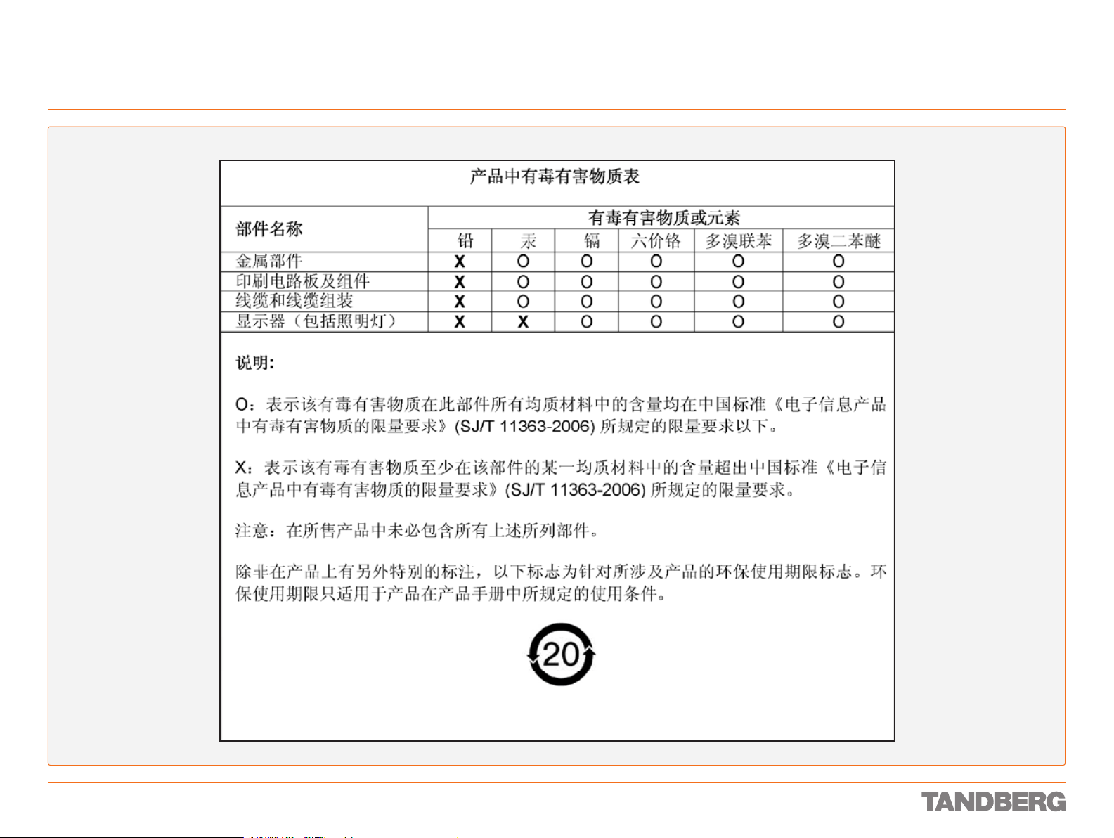
China RoHS Table
D 13887.08
MAY 2008
15
Page 16

What’s in the Shipping Box?
We recommend that you check out the
TANDBERG web site regularly for updated
versions of this manual:
http://www.tandberg.com/support/
documentation.php
This part of the Reference Guide for System Integrators
presents the contents of the shipping box to ease your
acceptance test as well as assist you in making sure
you’ve got everything with you if you need to take the
codec along for installation etc.
Page 17
What’s in the Shipping Box?
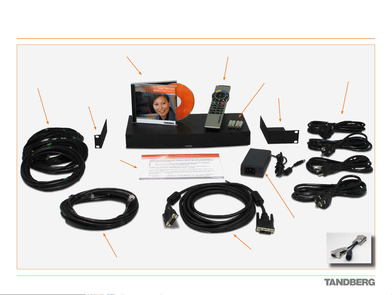
Contents of the 3000 MXP Codec Shipping Box
REFERENCE GUIDE FOR SYSTEM INTEGRATORS
TANDBERG 3000 MXP & 6000 MXP
4 ISDN BRI cables
(not included with the
NET version)
Rack mounting kit (I)
CD with user documentation
User
registration
card
Codec 3000 MXP
Remote control
Batteries for remote control
Rack mounting kit (II)
Up to 4 mains cables
(depending on region)
D 13887.08
MAY 2008
1 LAN / Ethernet cable
17
Video DVI–VGA cable
Power supply
Split cable for
non-TANDBERG WAVE II
cameras
Page 18

What’s in the Shipping Box?
Contents of the 6000 MXP Codec Shipping Box
REFERENCE GUIDE FOR SYSTEM INTEGRATORS
TANDBERG 3000 MXP & 6000 MXP
6 ISDN BRI cables
CD with user documentation
Rack mounting kit (I)
User
registration
card
Codec 6000 MXP
Remote control
Up to 4 mains cables
(depending on region)
Batteries for remote control
Rack mounting kit (II)
Mains
extension
cable
1 ISDN PRI cable
D 13887.08
MAY 2008
1 LAN / Ethernet cable
DVI–VGA cable
18
Page 19

Interfaces and Sockets – Codec 3000 MXP
We recommend that you check out the
TANDBERG web site regularly for updated
versions of this manual:
http://www.tandberg.com/support/
documentation.php
This part of the manual provides an in-depth presentation
of the rear panel sockets and interfaces of the Codec
3000 MXP, including the audio signal levels and the
formats supported.
Page 20
Interfaces and Sockets – Codec 3000 MXP
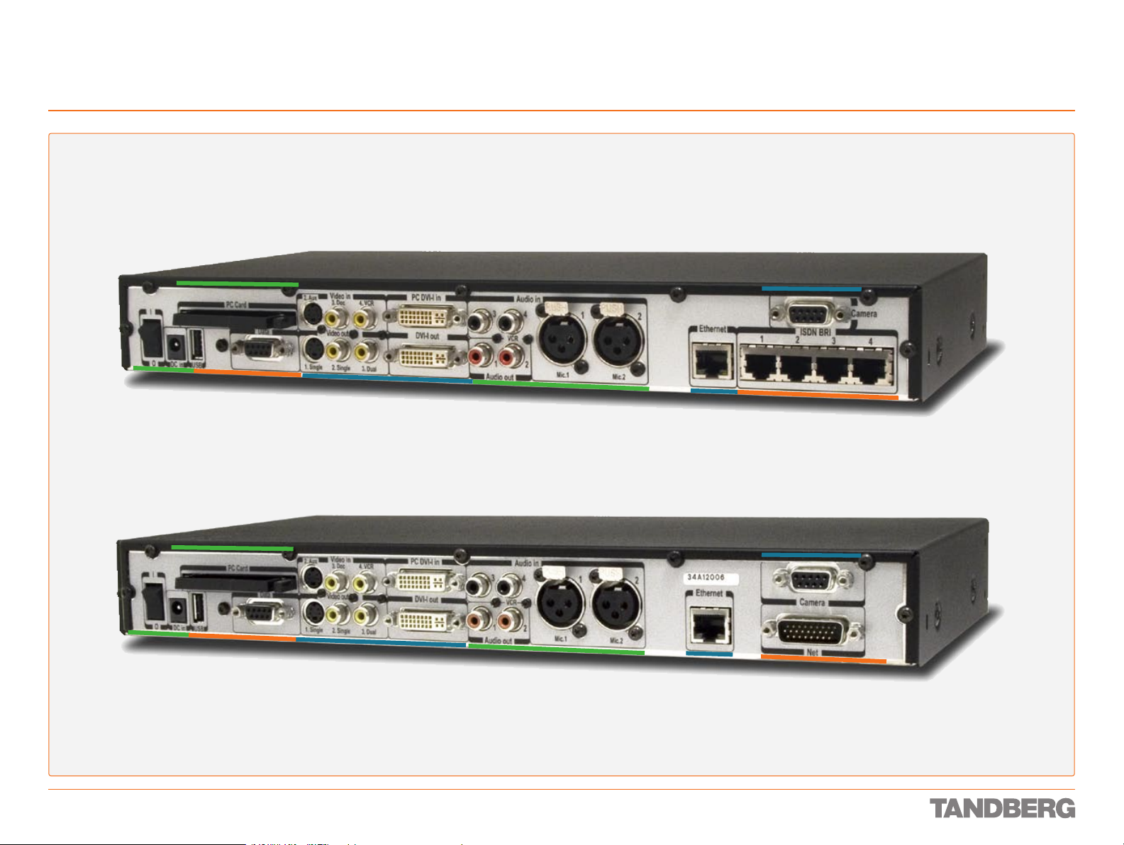
Rear Panel Socket– and Interface Groups
The Codec 3000 MXP comes in two avours – with ISDN BRI sockets (upper) or with Net socket (lower).
Codec 3000 M X P
REFERENCE GUIDE FOR SYSTEM INTEGRATORS
TANDBERG 3000 MXP & 6000 MXP
DC power socket
and On/Off switch
Codec 3000 M X P Net
DC power socket
and On/Off switch
PC card
Network
interface
sockets
PC card
Network
interface
sockets
Video sockets
Video sockets
Audio sockets
Audio sockets
Ethernet
Ethernet
Camera
ISDN BRI
Camera
Net socket
D 13887.08
MAY 2008
20
Page 21

Interfaces and Sockets – Codec 3000 MXP
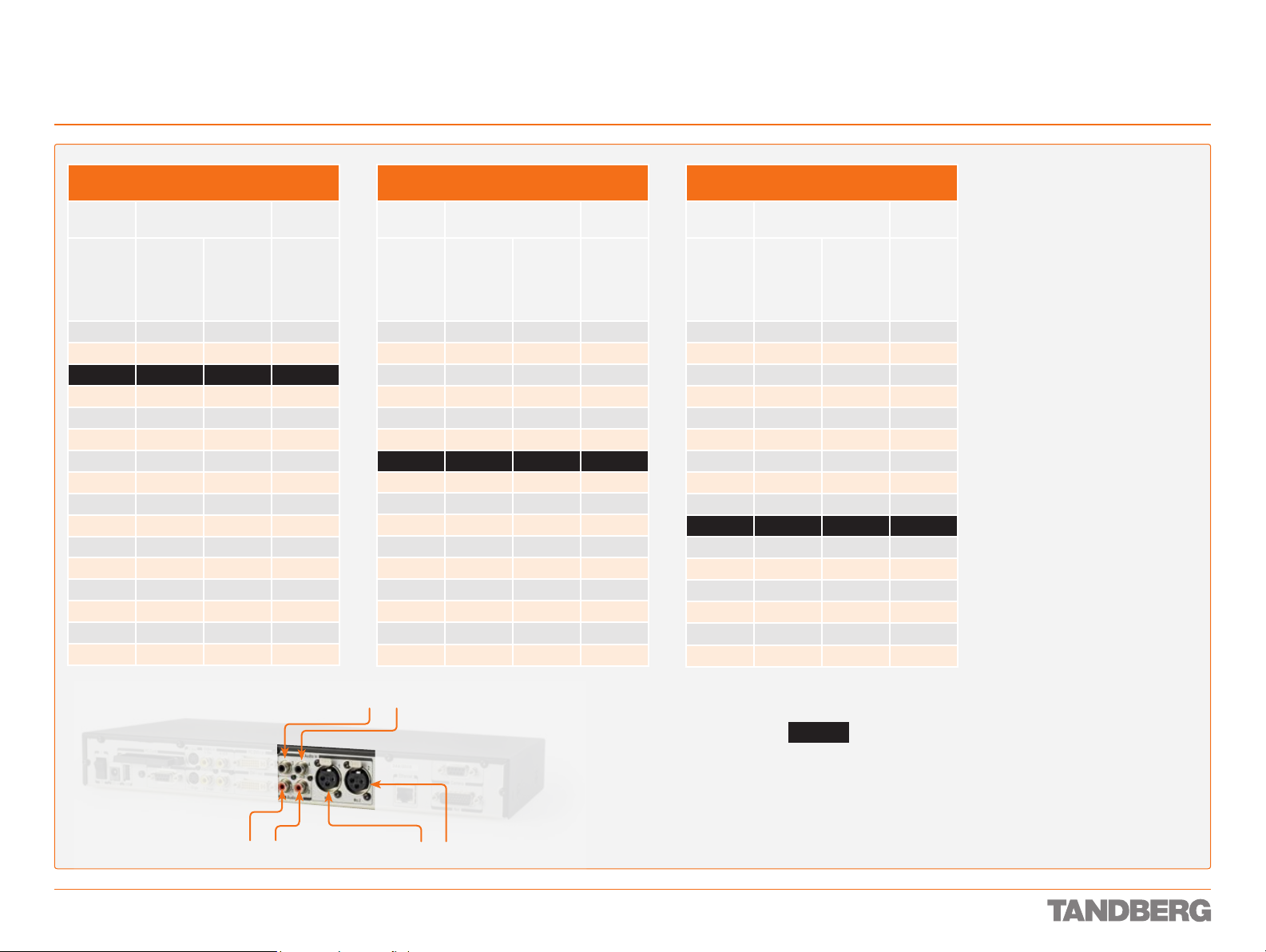
Audio Sockets
REFERENCE GUIDE FOR SYSTEM INTEGRATORS
TANDBERG 3000 MXP & 6000 MXP
Tip! Audio signal levels
expressed in volts and dBu
can be found overleaf.
Use Audio Input No. 3 to
connect to external playback
devices. This input can also
be congured as a microphone
NoTe! Audio inputs 3 &
4 are referred to as Line
input 1 & 2 in the API.
Tip! Unused, but connected
input. It will then function in
lieu of the Mic. 2 input and be
connected to Mic. 2’s echo
canceller (which can be turned
on/off).
audio inputs should be set
to Off to avoid unwanted
audio/noise.
Use Audio Output No. 1 to provide a mixed
signal of audio from far end and local
external devices connected to input 3 & 4 in
addition to dial tones.
This output should be connected to the local
loudspeaker system, which may, or may not,
include the TANDBERG Digital Natural Audio
Module.
For systems congured with stereo
speakers and SPDIF† active, the left and
right channel of the loudspeaker signal will
both be provided on this output.
For systems congured with stereo
speakers and SPDIF† not active, the
left channel of the loudspeaker signal
will be present on this output. The right
loudspeaker channel will be provided on
Audio Output No. 2.
RCA pin-out
External view of socket
GNDSignal
Use Audio Input No. 4 to
connect a VCR or DVD player
to the system. For systems
congured with stereo I/O,
connect the VCR/DVD right
channel to this input. This
input should be used when
connecting a telephone add-on
system.
Use Audio Output No. 2 (the VCR output) to
provide a mixed signal consisting of audio
from the local side (VCR not included) and
audio from the far end.
This output should be used when connecting a
telephone add-on system.
For system congured with stereo I/O and
with SPDIF† active on Audio Output No. 1, this
output will provide the VCR left channel stereo
information.
For systems congured with stereo I/O, stereo
speakers and SPDIF† not active, this output
will provide the right channel of the loudspeaker signal (the left channel will be provided on
the Audio Output No. 1).
†
SPDIF (Sony/Philips Digital Interface)
is used by the Digital Natural Audio module.
Tip! Audio Input No. 4 is not
equipped with an acoustic
echo canceller. Connecting a
microphone to this input can
therefore not be recommended.
Microphone Inputs Nos. 1–2.
Two balanced microphone
inputs for electret microphones
balanced, 24V phantom
powered via XLR connectors.
XLR pin-out
External view of socket
PIN 1: Gnd
12
PIN 2: Hot
PIN 3: Cold/neutral
3
Stereo Settings
Settings Output Response
Out 1 mode Stereo
Analogue Off Off Loudspeaker mono VCR
Analogue Off On Loudspeaker L
Analogue On Off Loudspeaker mono VCR
Analogue On On Loudspeaker L Loudspeaker R
SPDIF Off Off Loudspeaker mono VCR
SPDIF Off On Loudspeaker L & R VCR
SPDIF On Off Loudspeaker mono VCR
SPDIF On On Loudspeaker L & R VCR
I/O mode
Stereo
speakers
Audio Out 1 Audio Out 2
Loudspeaker R
Hardware Information
Microphone(s) Audio Input(s) Audio Outputs
Signal type Balanced Unbalanced
Socket XLR-F RCA/phono
Input impedance
Output impedance
Max input level when set to
min. input level
Max output level when set
to max. output level
Max input level when set to
max. input level
Max output level when set
to min. output level
Gain range 22.5 dB (16 steps of 1.5 dB)
Phantom power 24 V ± 5 %
Phantom power resistor
pin 2
Phantom power resistor
pin 3
Max phantom power
current
2400 W
(pin 2–3)
83 mVpp 15.5 Vpp
6.2 mVpp 1.2 Vpp
1200 W
1200 W
12 mA
10 kW
680 W
15.5 Vpp
1.2 Vpp
D 13887.08
MAY 2008
21
Page 22
Interfaces and Sockets – Codec 3000 MXP
Audio signal levels in Vpp and dBu
REFERENCE GUIDE FOR SYSTEM INTEGRATORS
TANDBERG 3000 MXP & 6000 MXP
Microphone Inputs 1 & 2
Signal levels
Signal
levels
Input
menu
level
setting
[dB] [mVpp] [dBu] [dBu]
0.0 83.0 –28.4 –46.4
1.5 69.8 –29.9 –47.9
3.0 58.8 –31.4 –49.4
4.5 49.4 –32.9 –50.9
6.0 41.6 –34.4 –52.4
7.5 35.0 –35.9 –53.9
9.0 29.4 –37.4 –55.4
10.5 24.8 –38.9 –56.9
12.0 20.8 –40.4 –58.4
13.5 17.5 –41.9 –59.9
15.0 14.8 –43.4 –61.4
16.5 12.4 –44.9 –62.9
18.0 10.4 –46.4 –64.4
19.5 8.8 –47.9 –65.9
21.0 7.4 –49.4 –67.4
22.5 6.2 –50.9 –68.9
Clipping levels Nominal
level
Audio Inputs 3 & 4
Signal levels
Signal
levels
Input
menu
level
setting
[dB] [Vpp] [dBu] [dBu]
0.0 15.5 17.0 –1.0
1.5 13.0 15.5 –2.5
3.0 11.0 14.0 –4.0
4.5 9.2 12.5 –5.5
6.0 7.8 11.0 –7.0
7.5 6.5 9.5 –8.5
9.0 5.5 8.0 –10.0
10.5 4.6 6.5 –11.5
12.0 3.9 5.0 –13.0
13.5 3.3 3.5 –14.5
15.0 2.8 2.0 –16.0
16.5 2.3 0.5 –17.5
18.0 2.0 -1.0 –19.0
19.5 1.6 -2.5 –20.5
21.0 1.4 -4.0 –22.0
22.5 1.2 -5.5 –23.5
Clipping levels Nominal
level
Audio Outputs 1 & 2
Signal levels
Signal
levels
Input
menu
level
setting
[dB] [Vpp] [dBu] [dBu]
10.5 3.9 5.0 –13.0
12.0 4.6 6.5 –11.5
13.5 5.5 8.0 –10.0
15.0 6.5 9.5 –8.5
16.5 7.8 11.0 –7.0
18.0 9.2 12.5 –5.5
19.5 11.0 14.0 –4.0
21.0 13.0 15.5 –2.5
22.5 15.5 17.0 –1.0
Absolute max output
level
0.0 1.2 –5.5 –23.5
1.5 1.4 –4.0 –22.0
3.0 1.6 –2.5 –20.5
4.5 1.9 –1.0 –19.0
6.0 2.3 0.5 –17.5
7.5 2.8 2.0 –16.0
9.0 3.3 3.5 –14.5
Nominal
level
NoTe! Audio inputs 3 & 4 are referred
to as Line input 1 & 2 in the API.
Tip! To convert dBu values to dBV,
subtract 2.2 dB from the dBu value.
example: –10 dBu => –12.2 dBV
NoTe! The input clipping levels and
the absolute max output levels all
assume sinusoidal signals for the dBu
values.
D 13887.08
MAY 2008
Audio outputs 1 & 2
Audio inputs 3 & 4
Microphone inputs 1 & 2
Default levels are denoted as follows:
–31.4
22
Page 23
Interfaces and Sockets – Codec 3000 MXP
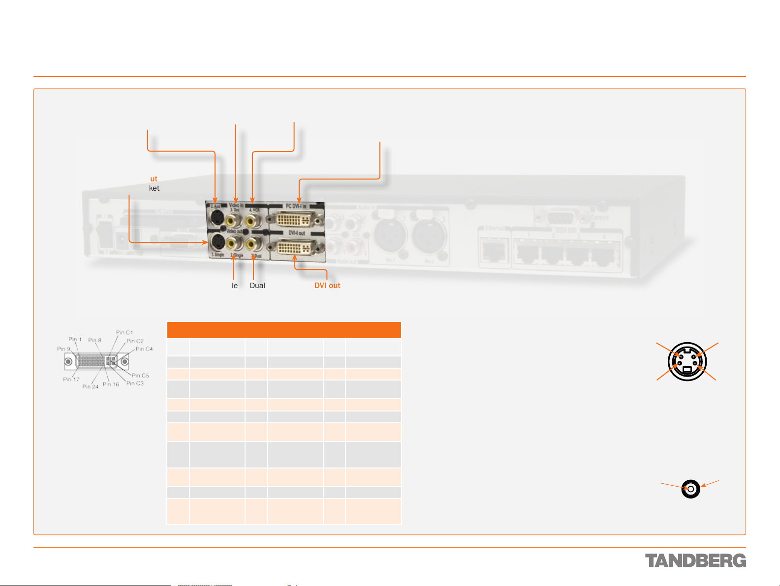
Video Sockets
REFERENCE GUIDE FOR SYSTEM INTEGRATORS
TANDBERG 3000 MXP & 6000 MXP
NoTe! The system
will automatically
adapt to a PAL or
S-video input
Mini-DIN socket
Aux. camera
NTSC input.
Single
S-video output
Mini-DIN socket
DVI-I pin-out
Note: TANDBERG supports DVI-D
Single -Link, DVI-A and DVI- I Single- Link format cables.
DVI- D cables transmit digital
T.M.D.S. signals, DVI-A cables
transmit analogue VGA signals
and DVI-I cables can transmit
either digital or analogue signals.
If your DVI cable is not long
enough, use extension cables.
Observe, however, that the
maximum cable length should not
exceed 5 m to avoid qualit y loss.
Composite video input RCA sockets
Doc. camera VCR
PC DVI-I input sockets
(Digital Video Interface,
Integrated digital
and analogue)
Single Dual
DVI output
Composite video output
RCA sockets
DVI-I Pin-out
Pin Assignment Pin Assignment Pin Assignment
1 T.M.D.S. Data 2– 9 T.M.D.S. Data 1– 17 T.M.D.S. Data 0–
2 T.M.D.S. Data 2+ 10 T.M.D.S. Data 1+ 18 T.M.D.S. Data 0+
3 T.M.D.S. Data 2/4
Shield
4 T.M.D.S. Data 4– 12 T.M.D.S. Data 3– 20 T.M.D.S. Data 5–
5 T.M.D.S. Data 4+ 13 T.M.D.S. Data 3+ 21 T.M.D.S. Data 5+
6 DDC Clock 14 +5 V power 22 T.M.D.S. Clock
7 DDC Data 15 GND
8 Analogue Vertical
Sync
C1 Analogue Red C2 Analogue Green C3 Analogue Blue
C4 Analogue
Horizontal Sync
11 T.M.D.S. Data 1/3
Shield
(return for +5 V,
HSync and Vsync)
16 Hot plug detect 24 T.M.D.S. Clock–
C5 Analogue GND
(analogue
R, G & B return)
19 T.M.D.S. Data 0/5
Shield
Shield
23 T.M.D.S. Clock+
Formats supported on DVI-I out:
SVGA (800 × 60 0) 75 Hz
XGA (1024 × 768) 6 0 Hz
SXGA (1280 × 1024) 60 Hz
HD720p (1280 × 720) 50 H z, 60 Hz
WXGA (128 0×768) 60 Hz
Formats supported on DVI-I in:
SVGA (800 × 60 0) 60 Hz, 72 Hz, 75 Hz , 85 Hz
XGA (1024 × 768) 6 0 Hz, 70 Hz, 75 Hz
SXGA (1280 × 1024) 60 Hz
HD720p (1280 × 720) 50 H z, 60 Hz
Do as follows to get WXGA:
1 VGA Out Quality must be set to Auto.
2 VGA Monitor Format must be set to Wide.
3 PC Picture Format must be set to Normal.
If you are using TANDBERG supplied monitors this will give WXGA out
when displaying graphics.
If non-TANDBERG provided displays are used, you must in addition
execute the command:
xConguration Video Outputs AllowWXGA: On
Levels
Composite: 1 Vpp, 75 W
S-Video (Y/C):
Y: 1 Vpp, 75 W
C (PAL): 0.3 Vpp, 75 W
C (NTSC): 0.28 Vpp, 75 W
S-video Mini-DIN pin-out
External view of socket
4
2
Pin 1: Ground (Luminance)
Pin 2: Ground (Chrominance)
Pin 3: Luminance (Y)
Pin 4: Chrominance (C)
RCA pin-out
External view of socket
Signal
GND
3
1
D 13887.08
MAY 2008
23
Page 24
Interfaces and Sockets – Codec 3000 MXP
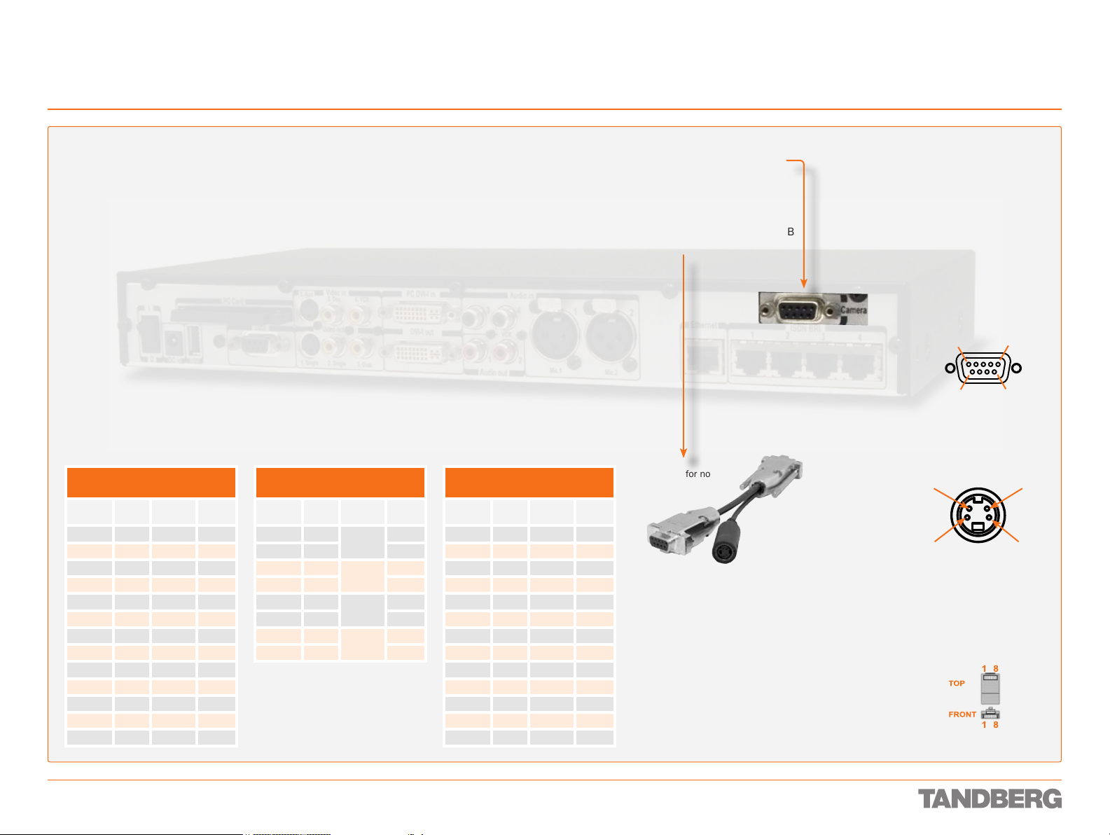
Camera Socket
REFERENCE GUIDE FOR SYSTEM INTEGRATORS
TANDBERG 3000 MXP & 6000 MXP
Tip! Wherever applicable, the use
of Category 5 cabling or better is
strongly recommended! For HD camera
applications, however, Category 7.5 is
required.
TANDBERG 3000 WAVE II
Camera cable pin-out
SIGNAL
NAME
+12V DC 8 — 4
GND 7 — 5
+12V DC 3 — 4
TXD 4 — 3
RXD 5 — 2
GND 6 — 5
GND 2 — 5
+12V DC 1 — 4
Y-GND — 1 8
C_GND — 2 1
Y — 3 9
C — 4 6
NC — — 7
RJ-45 S-VIDEO DSUB
TANDBERG HD 3000
Camera cable pin-out
SIGNAL
NAME
+12V DC 1
GND 2 1
Rx 3
TX 4 6
LVDS+ 5
LVDS– 6 3
GND 7
+12V DC 8 4
Cable is Category 7.5/ Class F AWG24.
Extreme care should be taken if you choose
to make your own version of this cable!
RJ-45 DSUB
Twisted
pair
Twisted
pair
Twisted
pair
Twisted
pair
4
2
9
5
Non-TANDBERG
Camera cable pin-out
SIGNAL
NAME
+12V DC 1 — 4
GND 2 — 5
+12V DC 3 — 4
TXD 4 — 3
RXD 5 — 2
GND 6 — 5
GND 7 — 5
+12V DC 8 — 4
Y-GND — 1 8
C_GND — 2 1
Y — 3 9
C — 4 6
NC — — 7
DSUB
Camera
S-VIDEO DSUB
Codec
Camera Connect the camera here. Use
a TANDBERG 3000 WAVE II Camera
cable or similar.
To connect a non-TANDBERG camera
use the split cable supplied. This cable
has a female D-SUB and an S-video
connector in one end and a male D-SUB
connector in the other end.
Codec side
Split cable for nonTANDBERG WAVE II
cameras
Camera side
9-pin D-SUB pin-out
External view of socket
5
1
69
S-video Mini-DIN pin-out
External view of socket
4
2
3
1
Pin 1: Ground (Luminance)
Pin 2: Ground (Chrominance)
Pin 3: Luminance (Y)
Pin 4: Chrominance (C)
RJ-45 Connector pin-out
D 13887.08
MAY 2008
24
Page 25
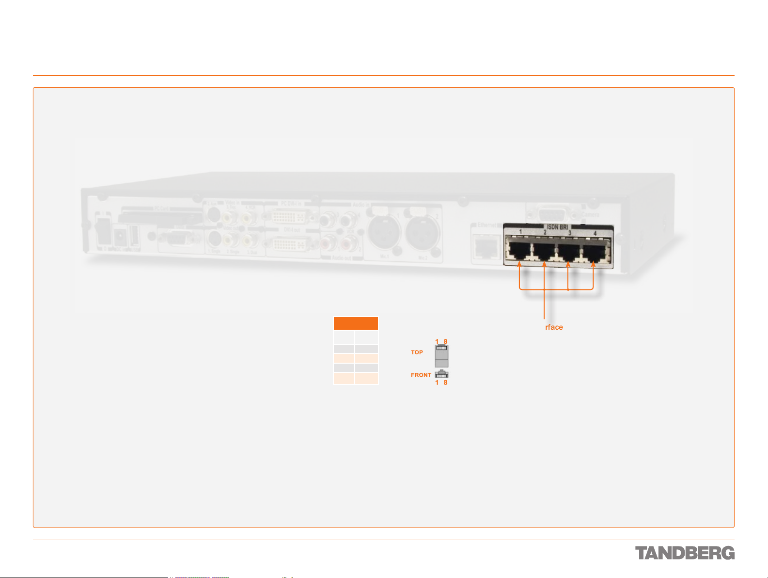
Interfaces and Sockets – Codec 3000 MXP
ISDN BRI sockets (not applicable to 3000 MXP Net)
Tip! Wherever applicable, the use
of Category 5 cabling or better is
strongly recommended! For HD camera
applications, however, Category 7.5 is
required.
REFERENCE GUIDE FOR SYSTEM INTEGRATORS
TANDBERG 3000 MXP & 6000 MXP
D 13887.08
MAY 2008
S/T Interface
BRI Pin out
Pin 3 TX+
Pin 4 RX+
Pin 5 RX–
Pin 6 TX–
RJ-45 Connector pin-out ISDN BRI interface. ISDN I.420
(RJ-45 Jack) Basic Rate Interface
S/T (2B + D), 128 kbps per ISDN
I/F. Use any standard BRI cable
to connect the Codec to BRI.
25
Page 26
Interfaces and Sockets – Codec 3000 MXP
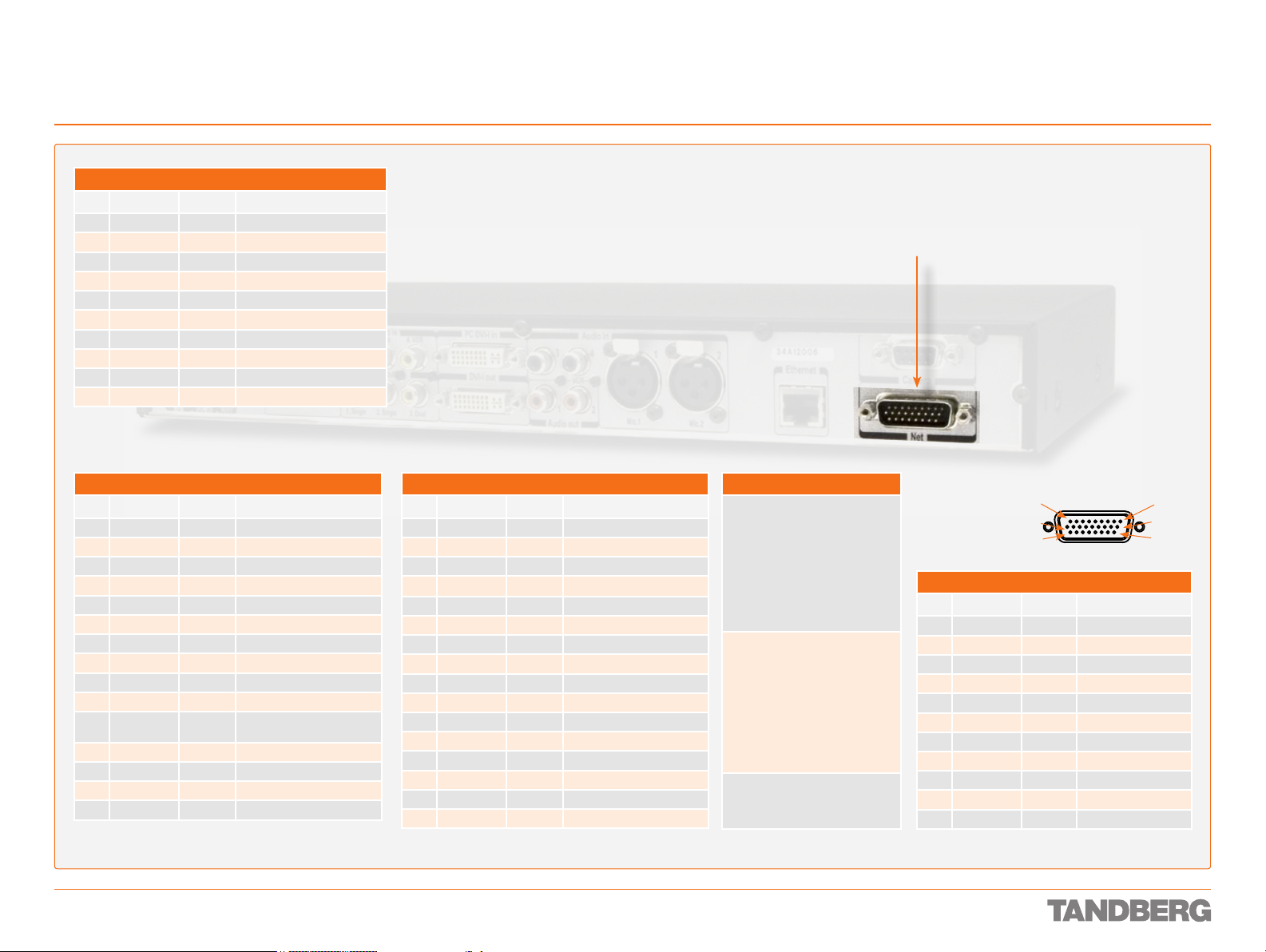
Net socket (applies to 3000 MXP Net only)
RS366 DTE → DCE
Pin Signal name Direction Description
1 FGND
2 DPR
3 ACR
4 CRQ
5 PND
6 DLO
7 NB1
8 NB2
9 NB4
10 NB8
V35 DTE → DCE
Pin Signal name Direction Description
1 FGND
11 SD(A)
12 SD(B)
13 RD(A)
14 RD(B)
15 SCR(A)
16 SCR(B)
17 SCT(A)
18 SCT(B)
19 GND
22 RLSD(CD)
23 RLSD(GND)
24 RI
25 LOS
26 DTR
1) This pin is conne cted to g round for corr ect op erati ons
1
1
Frame GND
↔
Digit Present
→
Abandon Call & Retry
←
Call Request
→
Present Next Digit
←
Data Line Occupied
←
Digit Bit 1
→
Digit Bit 2
→
Digit Bit 4
→
Digit Bit 8
→
Frame GND on equipment
↔
Send Data / Transmit
→
Send Data / Transmit
→
Receive Data
←
Receive Data
←
Signal Clock Receive
←
Signal Clock Receive
←
Signal Clock Transmit
←
Signal Clock Transmit
←
Signal GND
↔
Received Line Signal Detector /
←
Carrier Detect
Signal GND
←
Ring Indicator
←
Loss of Signal (KG194)
→
Data Terminal Ready
→
RS449 DTE → DCE
Pin Signal name Direction Description
1 FGND
11 SD(A)
12 SD(B)
13 RD(A)
14 RD(B)
15 RT(A)
16 RT(B)
17 ST(A)
18 ST(B)
19 GND
20 TR(A)
21 TR(B)
22 RR(A)
23 RR(B)
24 IC
25 LOS
Frame G ND is con nected to pin 1 on DTE
1) This pin is conne cted to g round for corr ect op erati ons
1
Frame GND
↔
Send Data
→
Send Data
→
Receive Data
←
Receive Data
←
Receive Timing
←
Send Timing
←
Send Timing
←
Send Timing
←
GND
↔
Terminal Ready
→
Terminal Ready
→
Carrier Detect / Receiver Ready
←
Carrier Detect / Receiver Ready
←
Incoming Call
←
Loss of Signal (KG194)
→
Net interface socket. 1 × X.21 / V.35 / RS449
with 1 × RS366 Call Control up to 2 Mbps
Note the following:
V.10 (RS42 3). For balanced signals a
0 = lo w volta ge, is dened as terminal
A positive with res pect to terminal B.
For unb alanc ed sign als a 0 = low volt-
age, is den ed as term inal po sitive
with re spec t to GND. Ca ble len gth
for Leased L ine Con trol shoul d not
exceed 2 0 m.
R S 3 6 6 . All balanced inputs and
outputs (A and B) use balanc ed line
signals acco rding to V.11 (RS 422),
while si ngle en ded sig nals are i n
accor danc e with V.10 (RS42 3). The
0 = lo w volta ge denitio ns are the
same as for V.10 above. Ma x cabl e
leng th, as for V.10 ab ove.
X.21. Signals are as for RS 366 above.
Cable length should not exceed 50 m.
REFERENCE GUIDE FOR SYSTEM INTEGRATORS
TANDBERG 3000 MXP & 6000 MXP
HD D-SUB 26 pin-out
External view of socket
10
19
X.21 DTE → DCE
Pin Signal name Direction Description
1 FGND
11 T(A)
12 T(B)
13 R(A)
14 R(B)
15 S(A)
16 S(B)
20 C(A)
21 C(B)
22 I(A)
23 I(B)
Frame GND
↔
Send Data / Transmit
→
Send Data / Transmit
→
Received Data / Receive
←
Received Data / Receive
←
Signal Element Timing
←
Signal Element Timing
←
Terminal Ready / Control
→
Terminal Ready / Control
→
Carrier Detect
←
Carrier Detect
←
91
18
26
D 13887.08
MAY 2008
26
Page 27
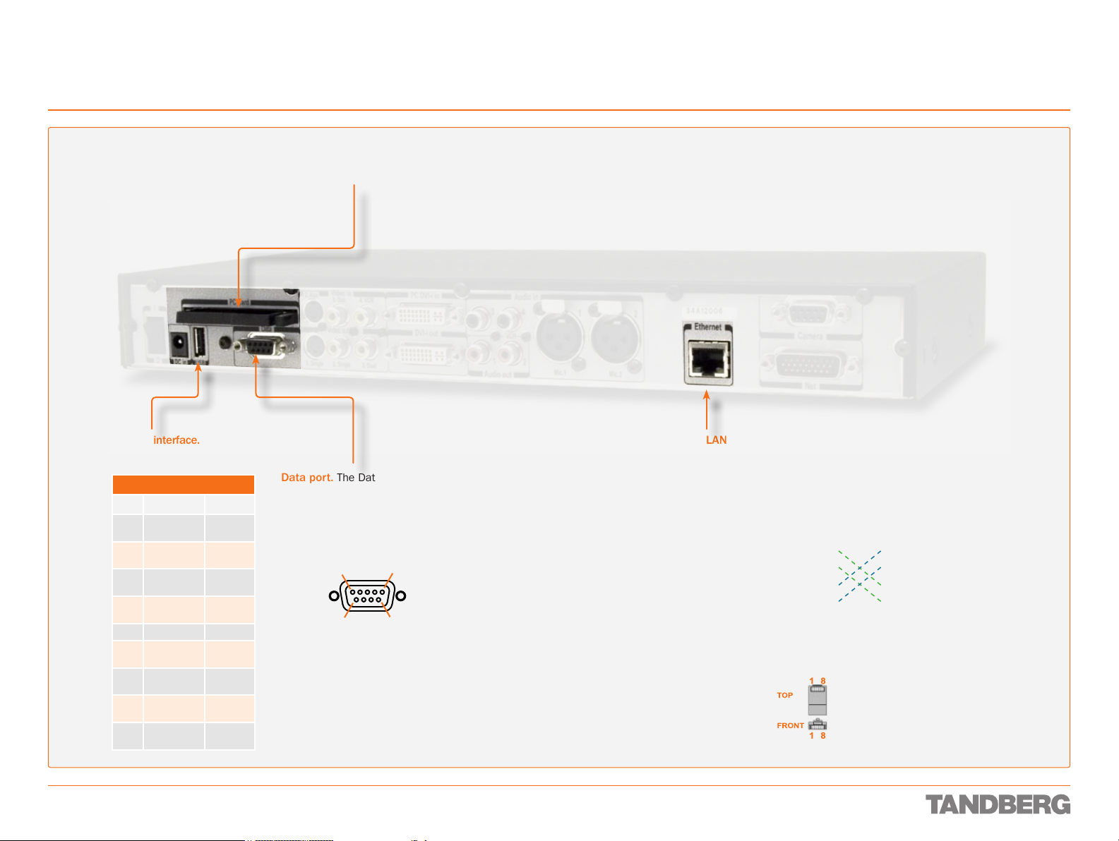
Interfaces and Sockets – Codec 3000 MXP
Network Interface Sockets
Tip! Wherever applicable, the use
of Category 5 cabling or better is
strongly recommended! For HD camera
applications, however, Category 7.5 is
required.
PC card. Wireless LAN PC card
may be inserted here.
REFERENCE GUIDE FOR SYSTEM INTEGRATORS
TANDBERG 3000 MXP & 6000 MXP
D 13887.08
MAY 2008
USB interface.
For future use.
Data port
Pin Signal name Direction
1 Carrier
detect, CD
2 Receive data,
RXD
3 Transmit
data, TXD
4 Data terminal
ready, DTR
5 Signal GND
6 Data set
ready, DSR
7 Ready to
send, RTS
8 Clear to
send, CTS
9 Ring
indicator, RI
From DCE
From DCE
To DCE
From DCE
From DCE
To DCE
From DCE
From DCE
Data port. The Data port is
implemented as a Digital Circuit
Terminating Equipment (DCE).
9-pin D-SUB pin-out
External view of socket
5
1
69
Tip! If you connect your Codec directly to a PC, make sure you set up
the system to use static TCP/IP settings. There will be no DHCP server
controlling the little LAN created by the computer and the Codec. When
conguring a back-to-back connection between the PC and the Codec,
make sure both static IP addresses exist on the same subnet.
27
Ethernet LAN (RJ-45 Jack) interface (10/100 Mb).
Up to 4 or 6 Mbps, depending on the bandwidth option installed. Use any standard Ethernet cable to
connect the Codec to a LAN.
If no LAN is available and the Codec is connected
directly to a computer, use a crossover cable.
Ethernet cable
1 ---------- 1
2 ---------- 2
3 ---------- 3
6 ---------- 6
Wiring diagram
standard cable
1 1
2 2
3 3
6 6
Wiring diagram
crossover cable
RJ-45 Connector pin-out
Page 28
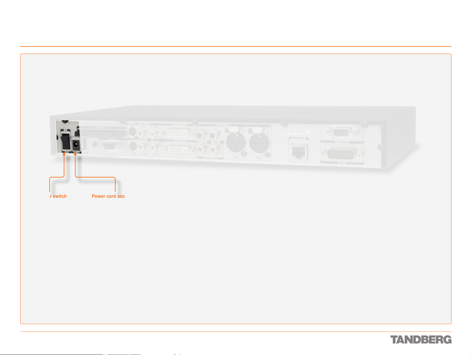
Interfaces and Sockets – Codec 3000 MXP
Power Socket & On/Off Switch
CauTioN! This equipment
must be earthed!
REFERENCE GUIDE FOR SYSTEM INTEGRATORS
TANDBERG 3000 MXP & 6000 MXP
Power switch
D 13887.08
MAY 2008
Power cord socket.
Accepts 12 V DC / 4.3 A
28
Page 29

Interfaces and Sockets – Codec 6000 MXP
We recommend that you check out the
TANDBERG web site regularly for updated
versions of this manual:
http://www.tandberg.com/support/
documentation.php
This part of the manual provides an in-depth presentation
of the rear panel sockets and interfaces of the Codec
6000 MXP, including the audio signal levels and the
formats supported.
Page 30
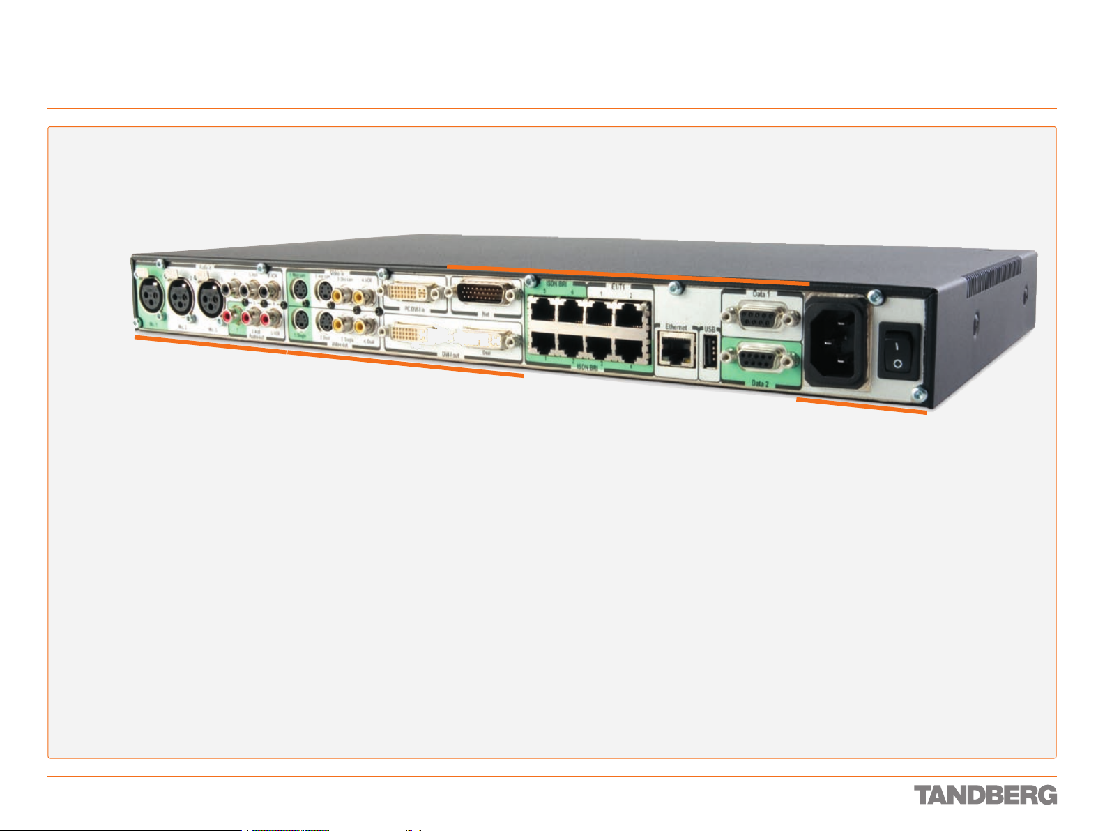
Interfaces and Sockets – Codec 6000 MXP
Rear Panel Socket– and Interface Groups
Audio sockets
Video sockets
REFERENCE GUIDE FOR SYSTEM INTEGRATORS
TANDBERG 3000 MXP & 6000 MXP
Network interface sockets
Power socket
and On/Off switch
D 13887.08
MAY 2008
30
Page 31

Interfaces and Sockets – Codec 6000 MXP
Audio Sockets
REFERENCE GUIDE FOR SYSTEM INTEGRATORS
TANDBERG 3000 MXP & 6000 MXP
Use Audio Input No. 4
to connect to an external
microphone amplier or to
an external mixer.
NoTe! Audio
inputs 4–6
are referred
to as Line
input 1–3 in
the API.
Microphone Inputs
Nos. 1–3.
Three balanced
microphone inputs for
electret microphones
balanced, 24V phantom
powered via XLR
connectors.
The phantom powering
of XLR socket No. 3 can
be switched off. The
Mic. input No. 3 will
then be a balanced line
level input.
XLR pin-out
External view of socket
12
Pin 1: Gnd
Pin 2: Hot
Pin 3: Cold/neutral
3
Use Audio Input No. 5 to
connect to external playback
devices or to telephone add-on
hybrids. For systems congured
with stereo I/O, connect the
VCR/DVD left channel to this
input.
Use Audio Output No. 1 to
provide a mixed signal of audio
from far end and local external
devices connected to input 5 &
6, in addition to dial tones.
This output should be connected
to the local loudspeaker system,
which may, or may not, include
the TANDBERG Digital Natural
Audio Module.
For systems congured with
stereo speakers and SPDIF†
active, the left and right channel
of the loudspeaker signal will
both be provided on this output.
For systems congured with
stereo speakers and SPDIF†
not active, the lef t channel of
the loudspeaker signal will be
present on this output. The right
loudspeaker channel will be
provided on Audio Output No. 2.
†
SPDIF (Sony/Philips Digital Interface)
is used by the Digital Natural Audio module.
Use Audio Input No. 6 to
connect a VCR or DVD player
to the system. For systems
congured with stereo I/O,
connect the VCR/DVD right
channel to this input.
RCA pin-out
External view of socket
GNDSignal
Use Audio Output No. 2 (the
AUX output) to provide a mixed
signal consisting of audio from
the local side (AUX input not
included) and audio from the
far end.
This output should be used
when connecting a telephone
add- on system.
For system congured with
stereo I/O and with SPDIF†
active on Audio Output No. 1,
this output will provide the VCR
left channel stereo information.
For systems congured with
stereo I/O, stereo speakers and
SPDIF† not active, this output
will provide the right channel of
the loudspeaker signal (the left
channel will be provided on the
Audio Output No. 1).
Tip! Audio inputs Nos. 5
& 6 are not equipped with
acoustic echo canceller.
Connecting microphones to
these inputs can therefore
not be recommended.
Tip! Unused, but connected
audio inputs should be set
to Off to avoid unwanted
audio/noise.
Tip! Audio signal levels
expressed in volts and dBu
can be found overleaf.
Use Audio Output No. 3
(the VCR output) to provide
a mixed signal consisting
of audio from the local side
(VCR input not included)
and audio from the far end.
This output should be used
when connecting a VCR to
the system.
For system congured with
stereo I/O and with SPDIF†
active on Audio Output No.
1, this output will provide
the VCR right channel
stereo information.
For systems congured
with stereo I/O, stereo
speakers and SPDIF† not
active, this output will
provide the mix of left and
right channel of the VCR
out signal.
Stereo Settings
Settings Output Response
Out 1
mode
Analogue Off Off Loudspeaker
Analogue Off On Loudspeaker L Loudspeaker R VCR
Analogue On Off Loudspeaker
Analogue On On Loudspeaker L Loudspeaker R VCR
SPDIF
SPDIF Off On Loudspeaker
SPDIF
SPDIF
Stereo
I/O mode
Off Off
On Off
On On
Stereo
speakers
Audio Out 1 Audio Out 2 Audio
mono
mono
Loudspeaker
mono
L & R
Loudspeaker
mono
Loudspeaker
L & R
Aux VCR
VCR L VCR R
Aux VCR
Aux VCR
VCR L VCR R
VCR L VCR R
Out 3
Hardware Information
Microphone(s) Audio Input(s) Audio Outputs
Signal type Balanced Unbalanced
Socket XLR-F RCA/phono
Input impedance
Output impedance
Max input level when set to
min. input level
Max output level when set to
max. output level
Max input level when set to
max. input level
Max output level when set to
min. output level
Gain range 22.5 dB (16 steps of 1.5 dB)
Phantom power 24 V ± 5 %
Phantom power resistor
pin 2
Phantom power resistor
pin 3
Max phantom power current 12 mA
2400 W
(pin 2–3)
83 mVpp 15.5 Vpp
6.2 mVpp 1.2 Vpp
1200 W
1200 W
10 kW
680 W
15.5 Vpp
1.2 Vpp
D 13887.08
MAY 2008
31
Page 32

Interfaces and Sockets – Codec 6000 MXP
Audio Signal Levels in Vpp and dBu
REFERENCE GUIDE FOR SYSTEM INTEGRATORS
TANDBERG 3000 MXP & 6000 MXP
Microphone Inputs 1, 2 & 3
Signal levels
Signal
levels
Input
menu level
setting
[dB] [mVpp] [dBu] [dBu]
0.0 83.0 –28.4 –46.4
1.5 69.8 –29.9 –47.9
3.0 58.8 –31.4 –49.4
4.5 49.4 –32.9 –50.9
6.0 41.6 –34.4 –52.4
7.5 35.0 –35.9 –53.9
9.0 29.4 –37.4 –55.4
10.5 24.8 –38.9 –56.9
12.0 20.8 –40.4 –58.4
13.5 17.5 –41.9 –59.9
15.0 14.8 –43.4 –61.4
16.5 12.4 –44.9 –62.9
18.0 10.4 –46.4 –64.4
19.5 8.8 –47.9 –65.9
21.0 7.4 –49.4 –67.4
22.5 6.2 –50.9 –68.9
This specication is always valid for mic 1 and 2, and
for mic 3 if mic level setting is selected.
Clipping levels Nominal
level
Microphone Input 3
Line level mode signal levels
Signal
levels
Input
menu level
setting
[dB] [Vpp] [dBu] [dBu]
0.0 15.5 17.0 –1.0
1.5 13.0 15.5 –2.5
3.0 11.0 14.0 –4.0
4.5 9.2 12.5 –5.5
6.0 7.8 11.0 –7.0
7.5 6.5 9.5 –8.5
9.0 5.5 8.0 –10.0
10.5 4.6 6.5 –11.5
12.0 3.9 5.0 –13.0
13.5 3.3 3.5 –14.5
15.0 2.8 2.0 –16.0
16.5 2.3 0.5 –17.5
18.0 2.0 –1.0 –19.0
19.5 1.6 –2.5 –20.5
21.0 1.4 –4.0 –22.0
22.5 1.2 –5.5 –23.5
This specication is valid for mic 3 if line level setting is
selected.
Clipping levels Nominal
level
Audio Inputs 4, 5 & 6
Signal levels
Signal
levels
Input
menu level
setting
[dB] [Vpp] [dBu] [dBu]
0.0 15.5 17.0 –1.0
1.5 13.0 15.5 –2.5
3.0 11.0 14.0 –4.0
4.5 9.2 12.5 –5.5
6.0 7.8 11.0 –7.0
7.5 6.5 9.5 –8.5
9.0 5.5 8.0 –10.0
10.5 4.6 6.5 –11.5
12.0 3.9 5.0 –13.0
13.5 3.3 3.5 –14.5
15.0 2.8 2.0 –16.0
16.5 2.3 0.5 –17.5
18.0 2.0 -1.0 –19.0
19.5 1.6 -2.5 –20.5
21.0 1.4 -4.0 –22.0
22.5 1.2 -5.5 –23.5
Default levels are denoted as follows:
Clipping levels Nominal
level
–31.4
Audio Outputs 1, 2 & 3
Signal levels
Signal
levels
Input
menu level
setting
[dB] [Vpp] [dBu] [dBu]
0.0 1.2 –5.5 –23.5
1.5 1.4 –4.0 –22.0
3.0 1.6 –2.5 –20.5
4.5 1.9 –1.0 –19.0
6.0 2.3 0.5 –17.5
7.5 2.8 2.0 –16.0
9.0 3.3 3.5 –14.5
10.5 3.9 5.0 –13.0
12.0 4.6 6.5 –11.5
13.5 5.5 8.0 –10.0
15.0 6.5 9.5 –8.5
16.5 7.8 11.0 –7.0
18.0 9.2 12.5 –5.5
19.5 11.0 14.0 –4.0
21.0 13.0 15.5 –2.5
22.5 15.5 17.0 –1.0
This specication is always valid for output 2 and 3,
and for output 1 at volume setting 15.
Absolute max output
level
Nominal
level
Audio inputs 4–6
Microphone
inputs 1–3 Audio outputs 1–3
D 13887.08
MAY 2008
NoTe: Audio inputs 4–6 are referred to as Line
input 1–3 in the API.
Tip: To convert dBu values to dBV, subtract
2.2 dB from the dBu value.
example: –10 dBu ≡ –12.2 dBV
NoTe: The input clipping levels and the
absolute max output levels all assume
sinusoidal signals for the dBu values.
32
Page 33

Interfaces and Sockets – Codec 6000 MXP
Video Sockets
REFERENCE GUIDE FOR SYSTEM INTEGRATORS
TANDBERG 3000 MXP & 6000 MXP
The system will
automatically
adapt to a PAL or
S-video input Mini-DIN sockets
Main camera Aux. camera
NTSC input.
Single Dual
S-video output
Mini-DIN sockets
DVI-I pin-out
Note: TANDBERG supports DVI-D
Single -Link, DVI-A and DVI- I Single- Link format cables.
DVI- D cables transmit digital
T.M.D.S. signals, DVI-A cables
transmit analogue VGA signals
and DVI-I cables can transmit
either digital or analogue signals.
If your DVI cable is not long
enough, use extension cables.
Observe, however, that the
maximum cable length should not
exceed 5 m to avoid qualit y loss.
Composite video input RCA sockets
Doc. camera VCR
Single Dual
Composite video output
Single Dual
DVI output
RCA sockets
DVI-I Pin-out
Pin Assignment Pin Assignment Pin Assignment
1 T.M.D.S. Data 2– 9 T.M.D.S. Data 1– 17 T.M.D.S. Data 0–
2 T.M.D.S. Data 2+ 10 T.M.D.S. Data 1+ 18 T.M.D.S. Data 0+
3 T.M.D.S. Data 2/4
Shield
4 T.M.D.S. Data 4– 12 T.M.D.S. Data 3– 20 T.M.D.S. Data 5–
5 T.M.D.S. Data 4+ 13 T.M.D.S. Data 3+ 21 T.M.D.S. Data 5+
6 DDC Clock 14 +5 V power 22 T.M.D.S. Clock
7 DDC Data 15 GND
8 Analogue Vertical
Sync
C1 Analogue Red C2 Analogue Green C3 Analogue Blue
C4 Analogue
Horizontal Sync
11 T.M.D.S. Data 1/3
Shield
(return for +5 V,
HSync and Vsync)
16 Hot plug detect 24 T.M.D.S. Clock–
C5 Analogue GND
(analogue
R, G & B return)
19 T.M.D.S. Data 0/5
Shield
Shield
23 T.M.D.S. Clock+
sockets
PC DVI-I input sockets
(Digital Video Interface,
Integrated digital
and analogue)
Formats supported on DVI-I out:
SVGA (800 × 60 0) 75 Hz
XGA (1024 × 768) 6 0 Hz
SXGA (1280 × 1024) 60 Hz
HD720p (1280 × 720) 50 H z, 60 Hz
WXGA (128 0×768) 60 Hz
Formats supported on DVI-I in:
SVGA (800 × 60 0) 60 Hz, 72 Hz, 75 Hz , 85 Hz
XGA (1024 × 768) 6 0 Hz, 70 Hz, 75 Hz
SXGA (1280 × 1024) 60 Hz
HD720p (1280 × 720) 50 H z, 60 Hz
Do as follows to get WXGA:
1 VGA Out Quality must be set to Auto.
2 VGA Monitor Format must be set to Wide.
3 PC Picture Format must be set to Normal.
If you are using TANDBERG supplied monitors this will give WXGA out
when displaying graphics.
If non-TANDBERG provided displays are used, you must in addition
execute the command:
xConguration Video Outputs AllowWXGA: On
Note that the S-Video/Composite outputs on the
6000 MXP are now by default turned off from
factory.
Ref. xConguration Video Outputs TV [1..2] Mode
Levels
Composite: 1 Vpp, 75 W
S-Video (Y/C):
Y: 1 Vpp, 75 W
C (PAL): 0.3 Vpp, 75 W
C (NTSC): 0.28 Vpp, 75 W
S-video Mini-DIN pin-out
External view of socket
4
2
Pin 1: Ground (Luminance)
Pin 2: Ground (Chrominance)
Pin 3: Luminance (Y)
Pin 4: Chrominance (C)
RCA pin-out
External view of socket
Signal
GND
3
1
D 13887.08
MAY 2008
33
Page 34

Interfaces and Sockets – Codec 6000 MXP
Net Interface Socket
Net interface socket. 1 × X.21 / V.35 / RS449
with 1 × RS366 Call Control up to 2 Mbps
V.35 DTE - DCE
Pin Signal Name Description
1 FGND Frame GND on equipment
11 SD(A) Send Data / Transmit
12 SD(B) Send Data / Transmit
13 RD(A) Receive Data
14 RD(B) Receive Data
15 SCR(A) Signal Clock Receive
16 SCR(B) Signal Clock Receive
17 SCT(A) Signal Clock Transmit
18 SCT(B) Signal Clock Transmit
19 GND
22 RLSD(CD) Received Line Signal
23 RLSD(GND)1Signal GND
24 RI Ring Indicator
25 LOS Loss of Signal (KG194)
26 DTR Data Terminal Ready
1) This pin is conne cted to g round for corr ect
operations
1
Signal GND
Detector / Carrier Detect
HD D-SUB 26 pin-out
External view of socket
10
19
RS449 DTE - DCE
Pin Signal Name Description
1 FGND Frame GND
11 SD(A) Send Data
12 SD(B) Send Data
13 RD(A) Receive Data
14 RD(B) Receive Data
15 RT(A) Receive Timing
16 RT(B) Send Timing
17 ST(A) Send Timing
18 ST(B) Send Timing
19 GND
20 TR(A) Terminal Ready
21 TR(B) Terminal Ready
22 RR(A) Carrier Detect / Receiver Ready
23 RR(B) Carrier Detect / Receiver Ready
24 IC Incoming Call
25 LOS Loss of Signal (KG194)
Frame G ND is con nected to pin 1 on DTE
1) This pin is conne cted to g round for corr ect op erati ons
1
GND
91
18
26
Note the following:
V.10 (RS423). For balanced signals a
“0” = low voltage, is dened as terminal
A positive with respect to terminal B. For
unbalanced signals a “0” = low voltage, is
dened as terminal positive with respect
to GND. Cable length for Leased Line
Control should not exceed 20 m.
R S 3 6 6 . All balanced inputs and outputs
(A and B) use balanced line signals
according to V.11 (RS 422), while single
ended signals are in accordance with V.10
(RS423). The “0” = low voltage denitions
are the same as for V.10 above. Max
cable length, as for V.10 above.
REFERENCE GUIDE FOR SYSTEM INTEGRATORS
TANDBERG 3000 MXP & 6000 MXP
RS366 DTE - DCE
Pin Signal Name Description
1 FGND Frame GND
2 DPR Digit Present
3 ACR Abandon Call & Retr y
4 CRQ Call Request
5 PND Present Next Digit
6 DLO Data Line Occupied
7 NB1 Digit Bit 1
8 NB2 Digit Bit 2
9 NB4 Digit Bit 4
10 NB8 Digit Bit 8
X.21 DTE - DCE
Pin Signal Name Description
1 FGND Frame GND
11 T(A) Send Data / Transmit
12 T(B) Send Data / Transmit
13 R(A) Received Data / Receive
14 R(B) Received Data / Receive
15 S(A) Signal Element Timing
16 S(B) Signal Element Timing
20 C(A) Terminal Ready / Control
21 C(B) Terminal Ready / Control
22 I(A) Carrier Detect
23 I(B) Carrier Detect
D 13887.08
MAY 2008
34
Page 35

Interfaces and Sockets – Codec 6000 MXP
Network Interface Sockets
REFERENCE GUIDE FOR SYSTEM INTEGRATORS
TANDBERG 3000 MXP & 6000 MXP
Tip! Wherever applicable, the use
of Category 5 cabling or better is
strongly recommended! For HD camera
applications, however, Category 7.5 is
required.
S/T Interface
BRI Pin-Out
Pin 3 TX+
Pin 4 RX+
Pin 5 RX–
Pin 6 TX–
ISDN BRI interface. ISDN I.420
(RJ-45 Jack) Basic Rate Interface
S/T (2B + D), 128 kbps per ISDN
I/F. Use any standard BRI cable
to connect the Codec to BRI.
ISDN PRI interface. 1 × PRI (RJ-45 Jack) Primary
Rate & Leased Line E1/T1 (G.703) Interface up to
2 Mbps. 1 × PRI (RJ-45 Jack) Primary Rate (for future
use). Use any standard PRI cable to connect the
Codec to PRI.
Ethernet LAN (RJ-45 Jack) interface (10/100 Mb).
Up to 4 or 6 Mbps, depending on the bandwidth option installed. Use any standard Ethernet cable to
connect the Codec to a LAN.
If no LAN is available and the Codec is connected
directly to a computer, use a crossover cable.
Ethernet cable
1 ---------- 1
2 ---------- 2
3 ---------- 3
6 ---------- 6
Wiring diagram
standard cable
E1/T1 Interface
PRI Pin-Out Crossover
PRI cable
Pin 1 RX+ 4
Pin 2 RX– 5
Pin 4 TX+ 1
Pin 5 TX– 2
1 1
2 2
3 3
6 6
Wiring diagram
crossover cable
D 13887.08
MAY 2008
RJ-45 Connector pin-out
Tip! If you connect your Codec directly to a PC, make sure you set up
the system to use static TCP/IP settings. There will be no DHCP server
controlling the little LAN created by the computer and the Codec. When
conguring a back-to-back connection between the PC and the Codec,
make sure both static IP addresses exist on the same subnet.
35
Page 36

Interfaces and Sockets – Codec 6000 MXP
Camera Sockets
Tip! Wherever applicable, the use
of Category 5 cabling or better is
strongly recommended! For HD camera
applications, however, Category 7.5 is
required.
S-video Mini-DIN pin-out
External view of socket
4
REFERENCE GUIDE FOR SYSTEM INTEGRATORS
TANDBERG 3000 MXP & 6000 MXP
3
D 13887.08
MAY 2008
2
1
Pin 1: Ground (Luminance)
Pin 2: Ground (Chrominance)
Pin 3: Luminance (Y)
Pin 4: Chrominance (C)
TANDBERG WAVE II
Camera cable pin-out
SIGNAL
NAME
+12V DC 8 4
GND 7 5
+12V DC 3 4
TXD 4 3
RXD 5 2
GND 6 5
GND 2 5
+12V DC 1 4
RJ-45 DSUB
36
TANDBERG HD 6000
Camera cable pin-out
SIGNAL
NAME
+12V DC 1
GND 2 5
Rx 3
TX 6 3
LVDS+ 4
LVDS– 5 6
GND 7
+12V DC 8 4
Cable is Category 7.5/ Class F AWG24.
Extreme care should be taken if you choose
to make your own version of this cable!
RJ-45 DSUB
Twisted
pair
Twisted
pair
Twisted
pair
Twisted
pair
4
2
1
5
9-pin D-SUB pin-out
External view of socket
5
1
69
RJ-45 Connector pin-out
Page 37

Interfaces and Sockets – Codec 6000 MXP
Data Ports
Data port 1 Data port 2
Pin Signal name Direction Signal name Direction
1 Carrier detect,
2 Receive data,
3 Transmit data,
41Data terminal
5 Signal GND
6 Data set ready,
7 Ready to send,
8 Clear to send,
9 Ring indicator,
CD
RXD
TXD
ready, DTR
DSR
RTS
CTS
RI
Data Ports
From DCE Carrier detect, CDFrom DCE
From DCE Receive data,
To DCE Transmit data,
From DCE 12 V / 1 A
From DCE
To DCE
From DCE
From DCE
RXD
TXD
Signal GND
Data set ready,
DSR
Ready to send,
RTS
Clear to send,
CTS
Ring indicator,
RI
From DCE
To DCE
From DCE
To DCE
From DCE
From DCE
USB interface.
For future use.
REFERENCE GUIDE FOR SYSTEM INTEGRATORS
TANDBERG 3000 MXP & 6000 MXP
9-pin D-SUB pin-out
External view of socket
5
1
69
Data port 1 (upper) and 2 (lower). The Data ports
are implemented as Digital Circuit Terminating
Equipment (DCE).
NoTe! The TANDBERG main camera is normally
connected to data port 2 and pin No. 4 provides
12 Vd c / 1 A to the main camera. Otherwise the pinouts are the same for the two data ports.
D 13887.08
MAY 2008
1) The TANDBERG main camera is normally connected to data port 2 and pin No. 4
provides 12 Vd c / 1 A to the main camera. Otherwise the pin-outs are the same for the
two data ports.
37
Page 38

Interfaces and Sockets – Codec 6000 MXP
Power Socket & On/Off Switch
CauTioN! This equipment must
be earthed!
REFERENCE GUIDE FOR SYSTEM INTEGRATORS
TANDBERG 3000 MXP & 6000 MXP
D 13887.08
MAY 2008
Accepts 100–240 V 50–60 Hz
Power cord socket
1 A max.
Power switch
38
Page 39

About the TANDBERG API
We recommend that you check out the
TANDBERG web site regularly for updated
versions of this manual:
http://www.tandberg.com/support/
documentation.php
The heart of the API is the TANDBERG API-Engine. This is
where all information is stored and processed. The APIengine can be accessed by an easy-to-use Command Line
Interface called XACLI using RS 232 or Telnet, or by the
TANDBERG XML API Ser vice (TXAS) over HTTP/HTTPS.
Both alternatives are described in detail in this section of
the User Guide.
Page 40

About the TANDBERG API
Introduction
REFERENCE GUIDE FOR SYSTEM INTEGRATORS
TANDBERG 3000 MXP & 6000 MXP
Basic Principles
The hear t of the API is the TANDBERG
API-Engine. This is where all information is
stored and processed. The API-engine can
be accessed by an easy-to -use Command
Line Interface called XACLI using RS 232
or Telnet, or by the TANDBERG XML API
Service (TXAS) over HTTP/HTTPS.
XACLI TXAS
R S 2 3 2
Telnet
API-Engine
Working with the API- engine is very similar
to working with catalogues and files on a
computer. All information is stored in a hierarchic tree structure which is accessible
from dif ferent interfaces.
When accessing the API-engine using
XACLI (RS 232 or Telnet), the information
is formatted in a proprietary Command Line
style or in XML formatting.
When accessing the API-engine using the
TXAS interface (HTTP/HTTPS), XML/SOAP
format ting is supported.
This is similar to viewing f iles on a computer; accessing catalogues on a Windows
computer using the Command Prompt
gives a dif ferent view than using Windows
Explorer, but the information is the same.
NOTE! New features on the TANDBERG
MXP will be supported on XACLI only.
HTTP
HTTPS
The TANDBERG API Engine
The TANDBERG API-Engine is optimized for easy, yet advanced, machine-
machine interaction between a TANDBERG system and an external control
application.
The main features can be summarized to:
Structuring of information•
Addressing using XPath (XML Path Language) or TANDBERG SimplePath•
Feedback •
Structuring of Information
An application programming interface (API) can be seen as a gate where information is exchanged between two systems – a control application and a target
system.
The control application transmits instructions to the target system, while the
target system supplies information about how these instructions are executed,
in addition to other system related information.
Consequently, the exchange of information can be divided into:
Information flowing 1. from target. This we call READ information (R). The (R)
should not be confused with the (r) used to indicate required parameters in
the Commands tables.
Information flowing 2. to target. This we call WRITE information (W).
If we now look at the TANDBERG systems we can identify three main types of
information
READ• information (R)
WRITE• information (W)
READ-WRITE• information (RW)
(R) READ information. This is Status Information about the system and system
processes, i.e. information generated by the system.
Typical examples include: status about ongoing calls, network status, conference status etc.
All status information is structured in a hierarchy, making up a database constantly being updated by the system to reflect process changes.
(W) WRITE information. This is Command Information the user/control applica-
tion supply to initiate an action.
Typical examples include: instructing the system to place a call, assigning floor
to a specific site, disconnecting a call etc.
A command is usually followed by a set of parameters to specify how the given
action is to be executed.
(RW) READ -WRITE information. This is Configuration Information defining sys-
tem settings. This information can both be supplied and read by the user/control application. Typical examples include: default call rate, baud rate of a serial
port, enabling/disabling of various features etc.
All configuration information is structured in a hierarchy making up a database
of system settings. But for the Configuration information, the data in the database can only be updated by the user/control application.
Addressing Using XPath or TANDBERG SimplePath
To address information in the hierarchic structure of Status and Configuration
information, the TANDBERG systems support abbreviated XML Path Language
(XPath) and a proprietar y notation called TANDBERG SimplePath (only available
using XACLI).
This allows the user/control application to address everything from a single
element of data (for example the call rate of a specific call) to larger parts of the
hierarchy (for example all information available for a given call).
Feedback
Feedback is an extremely powerful feature where the TANDBERG system
actively returns updated status and configuration information to the user/
control application whenever changes occur.
The user/control application can specify what par ts of the status and configuration hierarchies it wants to monitor by using XPath. The user/control application
can thereby limit the amount of information it receives from the target system to
only those parts being of interest for the given application. This will also reduce
the load on the link connecting the systems.
Feedback is supported on both X ACLI (RS232/Telnet) and TXAS (HTTP/
HTTPS) simultaneously.
The system uses TANDBERG SimplePath when presenting configurations.
XPath and TANDBERG SimplePath are described more thoroughly later in this
section of the manual.
The structuring of information together with XPath and TANDBERG SimplePath
for addressing, makes up powerful features like searchability and setting of
multiple instances of a configuration.
Examples are provided overleaf.
D 13887.08
MAY 2008
40
Page 41

About the TANDBERG API
REFERENCE GUIDE FOR SYSTEM INTEGRATORS
TANDBERG 3000 MXP & 6000 MXP
What Happened to the RS 232/Telnet Dataport
Interface Supported on the Classic Systems?
The TANDBERG MXP also supports the RS 232/Telnet Datapor t Inter face that was suppor ted on the Classic systems.
You may use any mixture of Classic Dataport commands and
XACLI commands on the same RS232/Telnet session. A
multitude of the commands overlaps, but XACLI offers more
flexibillity and gives access to the latest features supported
by the system.
We recommend the use of XACLI commands whenever
you write new control system modules and whenever you add
new features into existing control modules, but there is no
need to to rewrite already existing control modules based on
Classic commands.
The XACLI API is described in detail in this section of the User
Guide. The Classic Dataport Interface is described in the
TANDBERG 770-8000MXP API (Dataport User Guide), which is
available separately.
NOTE! New features on the TANDBERG MXP will be sup -
ported on XACLI only.
EXAMPLE: To configure the baudrate of serial port 1 to
9600:
Classic Dataport: sport data1 9600
XACLI: xconfiguration serialport 1 baudrate:
9600
Example 1
Example showing Serial Port configurations of a TANDBERG
6000 MXP codec, using the standard X ACLI formatting for
configurations:
xconfiguration serialport
*c xConfiguration SerialPort 1 BaudRate:
5760 0
*c xConfiguration SerialPort 1 Parity: None
*c xConfiguration SerialPort 1 DataBits: 8
*c xConfiguration SerialPort 1 StopBits: 1
*c xConfiguration SerialPort 1 Mode: Control
*c xConfiguration SerialPort 2 BaudRate: 9600
*c xConfiguration SerialPort 2 Parity: None
*c xConfiguration SerialPort 2 DataBits: 8
*c xConfiguration SerialPort 2 StopBits: 1
*c xConfiguration SerialPort 2 Mode: Auto
OK
Example 2
Example: To address the BaudRate element of serial port 2:
XPath
Each level is separated with a slash (‘/’). Item numbers are
added in brackets after the element name:
SerialPort[2]/BaudRate
Example
xconfiguration serialport[2]/baudrate
*c xConfiguration SerialPort 2 BaudRate: 9600
OK
TANDBERG SimplePath
Both levels and item numbers are separated with whitespaces:
SerialPort 2 BaudRate
Example
xconfiguration serialport 2 baudrate
*c xConfiguration SerialPort 2 BaudRate: 9600
OK
D 13887.08
MAY 2008
41
Page 42

About the TANDBERG API
XACLI
REFERENCE GUIDE FOR SYSTEM INTEGRATORS
TANDBERG 3000 MXP & 6000 MXP
Accessing XACLI
XACLI can be accessed through Telnet via the L AN interface
or through RS 232 by connecting a serial cable to the serial
interface connector, referred to as the Dataport. Eight Telnet
sessions can be connected to the TANDBERG MXP simultaneously, in addition to the RS 232 connection.
Connecting to XACLI using the Dataport (RS 232)
The RS 232 port is a 9 -pin, female, D -sub connector located
on the back of the TANDBERG MXP. The por t is configured
as a DCE (Data Communications Equipment). The RS 232
port is default set to 9600 baud, 8 data bits, none parity
and 1 stop bit from factory. The RS 232 port is also referred
to as the DATA POR T.
The RS 232 Datapor t on the 6000 MXP Codec
The RS 232 Datapor t on the 3000 M X P Codec
See also the pages on the 3000 MXP Dataports and the
6000 MXP Dataports in this User Guide. Note that one of
the RS 232 ports of the 6000 MXP Codec (the lower) is used
as a camera control socket.
Hardware & Cabling (RS 232)
The pin outs for the RS 232 are defined in the tables to the
right. Observe that the DTE (Data Terminal Equipment), could
be a PC or any other device capable of serial communication.
NOTE! A straight-through cable should be used between the
TANDBERG MXP’s RS 232 port and the DTE.
The lower table shows the recommended cable-wiring
scheme when connecting the TANDBERG MXP to a PC
through RS 232.
DTR and RTS are ignored. DSR, CD, and CTS are always asserted, while RI is not used.
Troubleshooting (RS 232)
If communication cannot be established between the PC/
terminal and the TANDBERG MXP’s Datapor t, the following
should be checked:
Verify that the serial cable is a straight-through 9-pin to •
9-pin cable
Confirm that the configuration of the PC/terminal’s •
serial RS 232 port is identical to the configuration of the
TANDBERG MXP RS 232 port.
Verify that the PC/terminal’s serial RS 232 port is working •
properly by connecting it back-to- back to another PC/
terminal and send characters in both directions.
Data Port (RS 232)
Pin Signal name Direction
1 Carrier detect, CD
2 Receive data, RXD
3 Transmit data, TXD
4 Data terminal ready, DTR
5 Signal GND
6 Data set ready, DSR
7 Ready to send, RTS
8 Clear to send, CTS
9 Ring indicator, RI
From DCE
From DCE
To DCE
From DCE
From DCE
To DCE
From DCE
From DCE
Cable wiring TANDBERG MXP ↔ PC via RS 232
TANDBERG MXP
DCE, 9 pin
1 CD
2 RD
3 TD
4 DTR
5 GND
6 DSR
7 RTS
8 CTS
9 RI
Direction PC
→
→
←
←
↔
→
←
→
→
DTE, 9 pin
1 CD
2 RD
3 TD
4 DTR
5 GND
6 DSR
7 RTS
8 CTS
9 RI
D 13887.08
MAY 2008
42
Page 43

About the TANDBERG API
XACLI – the Basics
REFERENCE GUIDE FOR SYSTEM INTEGRATORS
TANDBERG 3000 MXP & 6000 MXP
Root Commands
By typing ? or help after connecting to the
TANDBERG MXP using RS 232/Telnet, the
system will list all supported root com mands.
All root commands prefixed with an x
belongs to the XACLI inter face. These are
shown in orange colour in the table to the
right. All other root commands belong to
the Classic Dataport Interface (described in
a separate document).
NOTE! Classic Dataport commands and
XACLI commands can be used side by side.
However, the use of XACLI commands is
recommended whenever writing new control
system modules and whenever adding new
features into existing control modules, but
there is no need to rewrite existing code
based on the Classic commands.
NOTE! New features on the TANDBERG
MXP will be supported on XACLI only.
?
- User Commands about dumph221 layout-keyboard prisearch
access duovideo localdn protect
aim echoctrl los-duration rinfo
alrtvol enable los-inhibit rnumber
ansdelay encmode los-initial screensaver
audioagc encrypt los-polarity selfview
audiofeature encstatus los-retry sendnum
audiofeedback eventlog maxcall services
audioin extcam mcucommand snmp
audiolevel extcap mcudirectory spid
audiomix extname mculine spkr
audiomodule extswitch mcustat sport
audioout fallback menupassword sstring
autoans fecc mic statin
automute feed back monstat statout
autopip feinfo msn still
beep fevidsrc multisite streaming
bondingtimer g703settings netclock strictpassword
boot globdirectory netctrl sub
callstatus h239 netdtrpulse syslog
camcenter h323alias netisdn system name
cam move h323callmanager netpri telephony
campos h323gatekeeper netprole teltone
camsettings h323mtu netstat test
camsleepmode h323nat nettype traceroute
camtrack h323ports optionkey vgaout
chanstat h323prex pardial vidfeature
chat h323qos ping vidin
custominfo h323rate pip vidname
defcall h323status pldownspeed vidtone
defvalues h331mode preset-activate vnc
delbox help preset-list vol
dial ifcong preset-store websnapshots
directory ipaddress pressource xcommand
disable ipassignment pricable xconguration
disc ipconictcheck pricrc4 xdirectory
dispbox iplr prihighch xevent
dispparam ippassword prilowch xfeedback
disptxt irctrl primaxchan xgetxml
dltxt isdntrace prinsf xhistory
donotdist key prinum ber xpreferences
downspeed language prinumbrange xstatus
dualmon
OK
D 13887.08
MAY 2008
All root com mands prexed with an ‘x’ belong to the XACLI interface.
43
Page 44

About the TANDBERG API
XACLI – Main Types of Commands
REFERENCE GUIDE FOR SYSTEM INTEGRATORS
TANDBERG 3000 MXP & 6000 MXP
About Main Types of Commands
The XACLI is divided into three main t ypes
of commands (and a four th – see below),
reflecting the information types supported
by the TANDBERG API Engine.
The main types are:
Configuration-type commands•
Status -type commands•
Command-t ype commands•
In addition to the above sets of commands,
XACLI suppor ts the following set of special
commands:
Configuration Type Commands Command Type Commands
Commands defining system settings.
Configuration-type commands are either
supplied or read by the user. E.g. default
callrate, baudrate of a serial port, enabling/disabling of various features etc.
All Configurations are structured in a
hierarchy making up a database of system
settings.
Suppor ted Configuration -type commands:
xConfiguratio• n
xDirector• y
Commands returning information about
the system and system processes, i.e.
information generated by the system. E.g.
status about ongoing calls, network status,
conference status etc. All status information is structured in a hierarchy, making up
a database constantly being updated by
the system to reflect system and process
changes.
Suppor ted Status-type commands:
Status Type Commands
Commands instructing the system to perform an action. E.g. instructing the system
to place a call, assigning floor to a specific
site, disconnecting a call etc. A command
is usually followed by a set of parameters
to specify how the given action is to be
executed.
Suppor ted Command -type commands:
xComman• d
xStatu• s
xHistor• y
xEven• t
Special Commands
xfeedback is a command used to specify
what par ts of the configuration and status
hierarchies to monitor. Feedback will only
be issued on the RS 232/Telnet for which it
is specif ied. If connecting to the TANDBERG
MXP with multiple RS 232/Telnet sessions,
each session can define feedback individuall y.
More on this can be found in xfeedback.
xpreferences is used to set various prefer-
ences for the RS 232/Telnet sessions. Each
session can define preferences individually.
IMPORTANT! This command has various
settings to define the formatting of the X ACLI
output. It is therefore important to define settings to match the parser used on the control
system. X ACLI is designed to make parsing of
data from the TANDBERG MXP very simple.
More on this can be found in xpreferences.
xget xml gives access to the exact same
information as the Main types of commands
(xstatus, xhistory, xconfiguration etc.), but
returns the information XML formatted.
More on this can be found in xget xml.
D 13887.08
MAY 2008
44
Page 45

About the TANDBERG API
XACLI – Conguration Type Commands
REFERENCE GUIDE FOR SYSTEM INTEGRATORS
TANDBERG 3000 MXP & 6000 MXP
About Configuration Type Commands
All Configurations are organized in a hierarchic tree structure.
To get an overview of accessible top -level configuration elements within a
configuration-type command, type ? or help after the configuration-type com mands (xconfiguration/xdirectory), as shown in the example to the right.
TIP! To list all supported configurations with corresponding valuespace:
xConguration ??
Configurations consists of three parts:
A Configuration-type command (xConfiguration or xDirectory)1.
A Configuration path (address- expression)2.
A Configuration value3.
Configuration-type command
xConguration H323Gatekeeper Discovery: Manual
Configuration path
Configuration value
EXAMPLE:
xconguration ?
- User Congurations -
AdditionalCamera FTP OSD
AlertSpeaker G703 PacketlossDownSpeed
AlertTone H320 PictureProgram [1..4]
Audio H323 PresentationStart
AutoAnswer H323CallSetup Preset [1..15]
AutoDisplaySnapshot H323Gatekeeper QoS
AutoLayout H323Prex RemoteSwUpgrade
AutoPIP HTTP RTP
Bonding HTTPS Screensaver
CallManager IdReport SelfViewOnStartup
Camera [1..13] IEEE802.1x SerialPort [1..2]
CameraSleep IP SIP
CameraTracking IPMedia SNMP
Conference IPProtocol StartupVideoSource
CorporateDirectory IRControl StillImageSource
DefaultPIPPosition ISDN Streaming
DoNotDisturb Keyboard StrictPassword
DualMonitor Kiosk SystemUnit
DuoVideoSource LocalLayout T1
E1 Logo Telnet
Ethernet LoS TelnetChallenge
ExternalManager MainVideoSource Time
ExternalNetwork NAT UseAsLocalPCMonitor
ExternalServices NetProle [1..7] Video
FECC NTP VNC
FeedbackFilter OptionKey
D 13887.08
MAY 2008
OK
xdirectory ?
- Directory -
GlobalEntry [1..400] LocalEntry [1..200]
GroupEntry [1..50]
OK
45
Page 46

About the TANDBERG API
XACLI – Conguration Type Operation
REFERENCE GUIDE FOR SYSTEM INTEGRATORS
TANDBERG 3000 MXP & 6000 MXP
About Configuration Operations
Three operations can be performed on
congurations:
Configuration Help• Configuration Read• Configuration Set (Write)•
Note!
*h• is used when returning the result
of a help quer y
*c is used when returning the result •
of a read query
Nothing is used for configuration set•
*d is used when returning the result •
of an xdirectory read query.
Configuration Help Configuration Read
To get help on configurations, type ? after the configuration path
(address expression):
<configuration-type command> <address expression> ?
EXAMPLE:
xconguration h323gatekeeper discovery ?
*h xConguration H323Gatekeeper Discovery: <Manual/Auto>
OK
To read configurations from the system just type the root command
(xConfiguration/xDirectory) followed by the path (address
exp ression):
<configuration-type command> <address expression>
EXAMPLE:
xconguration h323gatekeeper discovery
*c xConguration H323Gatekeeper Discovery: Manual
OK
Configuration Set (Write)
Type a root command (xConfiguration/xDirectory) followed by
a valid path (address expression). The path must be terminated with a
colon before the value is added.
<configuration-type command> <address expression>: <value>
EXAMPLE:
xConguration H323Gatekeeper Discovery: Manual
D 13887.08
MAY 2008
46
Page 47

About the TANDBERG API
XACLI – Conguration Types
About Configuration Types Format for Value Types
REFERENCE GUIDE FOR SYSTEM INTEGRATORS
TANDBERG 3000 MXP & 6000 MXP
The system suppor ts the following value
types:
Integer values•
Literal values•
String values•
E164 string values (strings only contain -•
ing digits, ‘#’ and ‘*’)
IPv4 Address values•
IPv6 Address values•
IPv4 or IPv6 Address values•
Integer values:<x..y>
Defines the valid range for an integer input. x = min value, y = max value.
<1..100>
Literal values: <X/Y/../Z>
Defines the possible values for a given configuration.
<On/Off/Auto>
String values: <S: x, y>
Defines that the valid input for this configuration is a String with minimum length x and maximum length of y characters.
<S: 0, 49>
IPv4 Address values: <IPAddr>
Defines that the input must be an IPv4 address.
<IPAddr>
IPv6 Address values: <IPv6Addr: x, y>
Defines that the input must be an IPv6 address with minimum length x and maximum leng th y.
<IPv6Addr: 0, 43>
IPv4 or IPv6 Address values: <IPv4v6Addr: x, y>
Defines that the input must be an IPv4 or IPv6 address with minimum length x and maximum length y.
<IPv4v6Addr: 0, 43>
D 13887.08
MAY 2008
47
Page 48

About the TANDBERG API
XACLI – Command-type Commands – xcommands/xdirectory
REFERENCE GUIDE FOR SYSTEM INTEGRATORS
TANDBERG 3000 MXP & 6000 MXP
Getting an Overview
To get an overview of the supported command-type commands, type ? or help af ter the command-type command (xcommand) .
TIP! To list all supported configurations with corresponding valuespace:
xcommand ??
Command help
To get help on a specific command, type the command -type command (xcommand) – then a
command name followed by ? or help:
<command-type command> <com mand name> ?
EXAMPLE:
xcommand dial ?
*h xCommand Dial
Number: <S: 0, 60>
SecondNumber: <S: 0, 60>
SubAddress: <S: 0, 20>
CallRate: <Tlph/1xh221/2xh221/64/128/…/4096/Max/Auto>
Restrict: <On/Off>
NetProle: <1..7>
BillingCode: <S: 0, 16>
NOTE! Required parameters are identified by an (r) behind the parameter name.
EXAMPLE:
xcommand cameramove ?
Example Showing How to Get an Overview of Supported Commands
xcommand ?
- User Commands -
AlertToneTest DialLocalEntry LocalEntryDelete
AudioTestSignal DisconnectCall MessageBoxDelete
Boot DTMFSend MessageBoxDisplay
CallAccept DuoVideoStart PIPHide
CallMute DuoVideoStop PIPShow
CallMuteOutgoing FECCFocus PresetActivate
CameraFocus FECCMove PresetClear
CameraHalt FECCPresetActivate PresetStore
CameraMove FECCPresetStore ScreensaverActivate
CameraPosition FECCRequestStill ScreensaverDeactivate
CameraTrackingStart FECCSelectSource ScreensaverReset
CameraTrackingStop FeedbackDeregister SiteDisconnect
CameraWhiteBalance FeedbackRegister SiteView
ChairRelease FloorRelease SiteViewEnd
ChairTake FloorRequest SPIDAutoCongure
ConferenceDisconnect FloorToSite SStringSend
ConferenceTerminate FloorToSiteEnd StillImageSend
CorpDirGetNext GroupEntryAdd StreamingStart
CorpDirGetPrevious GroupEntryDelete StreamingStop
CorpDirSearch KeyDisable TextDelete
DefaultValuesSet KeyEnable TextDisplay
Dial KeyPress VirtualMonitorReset
DialGlobalEntry KeyRelease VirtualMonitorSet
DialGroupEntry LocalEntryAdd
OK
*h xCommand CameraMove
Camera(r): <1..4>
Direction(r): <Up/Down/Right/Left/In/Out>
OK
D 13887.08
MAY 2008
Note! The list provided here appears as an example only. There may be commands available,
not listed here.
48
Page 49

About the TANDBERG API
XACLI – Command-type Commands – Issuing a Command
Issuing a Command Command Response
REFERENCE GUIDE FOR SYSTEM INTEGRATORS
TANDBERG 3000 MXP & 6000 MXP
A command must start with the command-type command (xcommand), followed by a command name, followed
by a set of parameters. Parameters values are identified by specifying the parameter name followed by a ‘:’
<command-type command> <com mand name> <parameter:value> <parameter:value>...
EXAMPLE:
xcommand dial number:558458 restrict:on callrate:128 subaddress:10
If there are multiple instances of a parameter, the item number is added after the tag separated with a dot:
<command-type command> <com mand> <parameter.item:value> <parameter.item:value>...
EXAMPLE:
xcommand groupentryadd name:TANDBERG localentryid.1:15 localentryid.2:57
Sequence Notation (Optional)
<command-type root command> <command> <value> <value>...
When using this notation the parameter values must be entered in the sequence as stated in the help text:
EXAMPLE:
*h xCommand Dial
Num ber: <S: 0, 60>
SecondNum ber: <S: 0, 60>
SubAddress: <S: 0, 20>
CallRate: <Tlph/1xh221/2xh221/64/128/192/256/320/384/H0/512/768/1152/1472/1
920/2560/3072/4096/Ma x/A ut o>
Restrict: <On/Off>
NetProfile: <1..7>
BillingCode: <S: 0, 16>
To dial a participant with the following properties: Number: 666, SecondNumber:777, SubAddress: 8, CallRate:
128, Restrict: On
xcom mand dial 666 777 8 128 on
When issuing a command, the system will return a set of return values. The
response will by default be on the same format as the standard XACLI Status
format. The other suppor ted status formats (completepath/XML) are also
suppor ted – ref. xpreferences.
EXAMPLE
xcommand dial 558458
*r Result (status=OK):
CallRef: 1
LogTag: 6
*r/end
OK
If complete path is enabled for the RS-232/Telnet session
(“xpreferences completepath on”):
EXAMPLE
xcom dial 558458
*r Result (status=OK):
*r Result CallRef: 1
*r Result LogTag: 4
OK
Combination of Markup Notation and Sequence (Optional)
A combination of markup notation and sequence is also supported. The
marked parameters will be assigned the user entered values first, then the
system will assign the sequence entered parameters for the parameters not
yet having been assigned a value:
EXAMPLE:
xcommand dial 666 restrict:on 777 8 128
NOTE! When using XACLI as a machine-machine interface we recommend that
you use markup notation and always supply complete tag names.
D 13887.08
MAY 2008
49
Page 50

About the TANDBERG API
XACLI – Command-type Commands – Parameter Value Types
REFERENCE GUIDE FOR SYSTEM INTEGRATORS
TANDBERG 3000 MXP & 6000 MXP
Command Parameter Value Types
The system suppor ts the following value types:
Integer values•
Literal values•
String values•
E164 string values (strings only containing digits, •
‘#’ and ‘*’)
IPv4 Address values•
IPv6 Address values•
IPv4 or IPv6 Address values•
Format for Value Types
Integer values:<x..y>
Defines the valid range for an integer input. x = min value, y = max value.
<1..100>
Literal values: <X/Y/../Z>
Defines the possible values for a given configuration.
<On/Off/Auto>
String values: <S: x, y>
Defines that the valid input for this configuration is a String with minimum length x and maximum length
of y characters.
<S: 0, 49>
IPv4 Address values: <IPAddr>
Defines that the input must be an IPv4 address.
<IPAddr>
IPv6 Address values: <IPv6Addr: x, y>
Defines that the input must be an IPv6 address with minimum length x and maximum leng th y.
<IPv6Addr: 0, 43>
D 13887.08
MAY 2008
IPv4 or IPv6 Address values: <IPv4v6Addr: x, y>
Defines that the input must be an IPv4 or IPv6 address with minimum length x and maximum length y.
<IPv4v6Addr: 0, 43>
50
Page 51

About the TANDBERG API
XACLI – Status Type Commands
REFERENCE GUIDE FOR SYSTEM INTEGRATORS
TANDBERG 3000 MXP & 6000 MXP
About Status Type Commands
All Status information is organized in a
hierarchic tree structure.
To get an overview of accessible top level status elements within a statustype command, type ? or help af ter the
status-type commands (xstatus/xhistory/xevent).
Understanding Status
Information Structuring
All Status information is organized in a
hierarchic tree structure, ver y much like
files and folders on a computer. The
tree structure consists of containerelements (folders) and value elements
(files). Container-elements contains
sub- elements, while value elements
contain values. All elements have an
element name and an element item
number. There can exist multiple
instances of an element.
An element can also have various
attributes. At tributes are used to add
meta information to an element. The
sub-structure of a container-element may
vary depending on the attribute values.
The relationship between attribute values
of a given element and its underlying substructure can be read from the sections
documenting the various status elements.
E.g. a call that is disconnected does not
contain any data (except a disconnect
cause value), while an active call contains
information about bandwidths, protocols,
channels etc.
EXAMPLE
Defining Element names, Values, Attributes, and Item No.:
xstatus call 1
*s Call 1 (status=Synced, type=Vtlph, protocol=H323, direction=Outgoing, logTag=1):
CallRate: 768
RemoteNumber: “558458”
Mute: Off
Microphone: Off
Duration: 20
MuteOutgoing: Off
Channels 1 (type=Incoming):
Video 2 (status=Inactive): /
Data (status=Inactive): /
*s/end
OK
In the above example. Element names are shown in orange. Values are shown in green. Attributes are shown in magenta. Item No. is shown in cyan
EXAMPLE
xstatus ?
- Status -
Audio ExternalNetwork RemoteSwUpgrade
BRI [1..6] FarEndInformation Screensaver
Call [1..11] Feedback [1..3] SIP
Camera [1..13] G703 SoftwareUpgrade
CameraTracking H323Gatekeeper SystemUnit
Conference IP VirtualMonitor [1..4]
Ethernet NTP Warning [1..10]
ExternalManager PRI
OK
.
. (some lines have been removed for clarity)
.
EXAMPLE
xhistory ?
- History -
Call [1..20]
OK
xevent ?
- Event -
AuthenticationFailure MessageBoxResult
CallDisconnected PacketlossDownSpeed
CallStatisticsIP [1..11] SString
CallSuccessful SystemActivity
DownspeedingFinished
OK
D 13887.08
MAY 2008
51
Page 52

About the TANDBERG API
XACLI – Status Type Commands – Default Formatting
REFERENCE GUIDE FOR SYSTEM INTEGRATORS
TANDBERG 3000 MXP & 6000 MXP
About Status Type Commands Formatting
XACLI suppor ts three different formattings for status
information:
Default XACLI format ting, provides good human •
readability, compact format. However, a custom parser
must be used
Complete Path formatting. Recommended when parsing •
the information line by line.
XML formatting – to be used when using an XML-parser.•
Default XACLI Formatting
The root-element is prefixed with • *s (for status), *e (for
event), or *l (for history log)
Root-element end is designated by a • *s/e n d (*e/e n d
or *l/e n d respectively)
To write a parser for this format, the parser must keep •
track of the levels by counting white spaces. The indent
is increased by two whitespaces for each level. Unless
link throughput is an issue, we recommend the use
of Complete Path Formatting instead of Default XACLI
format ting when parsing information sent from the codec.
About the Examples Provided Here
From the example showing status for a disconnected call
(upper right), we can see that the call element now only
contains one element; the value- element Cause. The subelements that were present when the call was active (lower
right example) are no longer valid (i.e. it makes no sense to
ask for out going video resolution for a disconnected call).
EXAMPLE showing status for a disconnected call.
xstatus call 1
*s Call 1 (status=Disconnected, type=NA, protocol=NA, direction=NA, logTag=NA):
Cause: 16
*s/end
OK
EXAMPLE showing status for an active call.
xstatus call 1
*s Call 1 (status=Synced, type=Vtlph, protocol=H323, direction=Outgoing, logTag=2):
CallRate: 768
RemoteNumber: “558458”
Mute: Off
Microphone: Off
Duration: 10
MuteOutgoing: Off
Channels 1 (type=Incoming):
Rate: 768
Restrict: Off
Encryption (status=Off): /
Audio (status=Active):
Protocol: G722
Rate: 64
Video 1 (status=Active):
Protocol: H264
Resolution: CIF
Rate: 704
Video 2 (status=Inactive): /
Data (status=Inactive): /
Channels 2 (type=Outgoing):
Rate: 768
Restrict: Off
Encryption (status=Off): /
Audio (status=Active):
Protocol: G722
Rate: 64
Video 1 (status=Active):
Protocol: H264
Resolution: CIF
Rate: 704
Video 2 (status=Inactive): /
Data (status=Inactive): /
*s/end
D 13887.08
MAY 2008
52
Page 53

About the TANDBERG API
XACLI – Status Type Commands – Complete Path Formatting
REFERENCE GUIDE FOR SYSTEM INTEGRATORS
TANDBERG 3000 MXP & 6000 MXP
About Status Type Commands Formatting
XACLI suppor ts three different formattings for status
information:
Default XACLI format ting, provides good human •
readability, compact format. However, a custom parser
must be used
Complete Path formatting. Recommended when parsing •
the information line by line.
XML formatting – to be used when using an XML-parser.•
About Complete Path formatting
The following should be obser ved:
Complete Path formatting is recommended for easy •
parsing
All lines are prefixed with • *s (for status), *e (for event),
or *l (for histor ylog)
The complete path to an element is supplied on all lines•
The parser can work line by line•
Root-element end is designated by a *s/end (*e/end or •
*l/end respectively).
NOTE! Complete Path formatting is enabled by: “xprefer-
ences completepath on”, described later in this section of
the User Guide.
NOTE! the xpreferences is a session specific command and
must be issued every time the control application connects
to the codec.
EXAMPLE
xpreferences completepath on
OK
xstatus call 1
*s Call 1 (status=Synced, type=Vtlph, protocol=H323, direction=Outgoing, logTag=2):
*s Call 1 CallRate: 768
*s Call 1 RemoteNumber: “558458”
*s Call 1 Mute: Off
*s Call 1 Microphone: Off
*s Call 1 Duration: 527
*s Call 1 MuteOutgoing: Off
*s Call 1 Channels 1 (type=Incoming):
*s Call 1 Channels 1 Rate: 768
*s Call 1 Channels 1 Restrict: Off
*s Call 1 Channels 1 Encryption (status=Off): /
*s Call 1 Channels 1 Audio (status=Active):
*s Call 1 Channels 1 Audio Protocol: G722
*s Call 1 Channels 1 Audio Rate: 64
*s Call 1 Channels 1 Video 1 (status=Active):
*s Call 1 Channels 1 Video 1 Protocol: H264
*s Call 1 Channels 1 Video 1 Resolution: CIF
*s Call 1 Channels 1 Video 1 Rate: 704
*s Call 1 Channels 1 Video 2 (status=Inactive): /
*s Call 1 Channels 1 Data (status=Inactive): /
*s Call 1 Channels 2 (type=Outgoing):
*s Call 1 Channels 2 Rate: 768
*s Call 1 Channels 2 Restrict: Off
*s Call 1 Channels 2 Encryption (status=Off): /
*s Call 1 Channels 2 Audio (status=Active):
*s Call 1 Channels 2 Audio Protocol: G722
*s Call 1 Channels 2 Audio Rate: 64
*s Call 1 Channels 2 Video 1 (status=Active):
*s Call 1 Channels 2 Video 1 Protocol: H264
*s Call 1 Channels 2 Video 1 Resolution: CIF
*s Call 1 Channels 2 Video 1 Rate: 704
*s Call 1 Channels 2 Video 2 (status=Inactive): /
*s Call 1 Channels 2 Data (status=Inactive): /
*s/end
D 13887.08
MAY 2008
OK
53
Page 54

About the TANDBERG API
XACLI – Status Type Commands – XML Formatting
REFERENCE GUIDE FOR SYSTEM INTEGRATORS
TANDBERG 3000 MXP & 6000 MXP
About Status Type Commands Formatting
XACLI suppor ts three different formattings for status
information:
Default XACLI format ting, provides good human •
readability, compact format. However, a custom parser
must be used
Complete Path formatting. Recommended when parsing •
the information line by line.
XML formatting – to be used when using an XML-parser.•
About XML Formatting
The following should be obser ved:
To be used when the control application is using an XML •
parser
XML formatting is used when polling for information using •
the special command xget xml, described later in this section of the manual.
To enable XML formatting on feedback issued from the •
codec, the special command xpreferences should be
used.
EXAMPLE
xgetxml status/call[1]
<Status>
<Call item=”1” status=”Synced” type=”Vtlph” protocol=”H323” direction=”Outgoing” logTag=”2”>
<CallRate item=”1”>768</CallRate>
<RemoteNumber item=”1”>558458</RemoteNumber>
<Mute item=”1”>Off</Mute>
<Microphone item=”1”>Off</Microphone>
<Duration item=”1”>887</Duration>
<MuteOutgoing item=”1”>Off</MuteOutgoing>
<Channels item=”1” type=”Incoming”>
<Rate item=”1”>768</Rate>
<Restrict item=”1”>Off</Restrict>
<Encryption item=”1” status=”Off”/>
<Audio item=”1” status=”Active”>
<Protocol item=”1”>G722</Protocol>
<Rate item=”1”>64</Rate>
</Audio>
<Video item=”1” status=”Active”>
<Protocol item=”1”>H264</Protocol>
<Resolution item=”1”>CIF</Resolution>
<Rate item=”1”>704</Rate>
</Video>
<Video item=”2” status=”Inactive”/>
<Data item=”1” status=”Inactive”/>
</Channels>
<Channels item=”2” type=”Outgoing”>
<Rate item=”1”>768</Rate>
<Restrict item=”1”>Off</Restrict>
<Encryption item=”1” status=”Off”/>
<Audio item=”1” status=”Active”>
<Protocol item=”1”>G722</Protocol>
<Rate item=”1”>64</Rate>
</Audio>
<Video item=”1” status=”Active”>
<Protocol item=”1”>H264</Protocol>
<Resolution item=”1”>CIF</Resolution>
<Rate item=”1”>704</Rate>
</Video>
<Video item=”2” status=”Inactive”/>
<Data item=”1” status=”Inactive”/>
</Channels>
</Call>
</Status>
OK
D 13887.08
MAY 2008
54
Page 55

About the TANDBERG API
XACLI – Status Type Commands – Addressing Status Information
REFERENCE GUIDE FOR SYSTEM INTEGRATORS
TANDBERG 3000 MXP & 6000 MXP
About Addressing Status Information
You address status information by supplying a status-type
command followed by an address-expression (XPath or
TANDBERG SimplePath):
<status-type command> <address expression>
See example 1 a) for an illustration.
If complete path is enabled for the RS 232/Telnet session
(xpreferences completepath on), it will look like
example 1 b).
As a second set of examples let us consider a situation
where the user wants to know Audio status for both incoming
and outgoing channels for Call 1. This is shown in examples
2 a) and 2 b).
EXAMPLE 1 a) Addressing status information, user wants to know callrate of call 1:
xstatus call 1 callrate
*s Call 1 (status=Synced, type=Vtlph, protocol=H323, direction=Outgoing, logTag=3):
CallRate: 768
*s/end
OK
EXAMPLE 1 b) xpreferences completepath set to on:
xstatus call 1 callrate
*s Call 1 (status=Synced, type=Vtlph, protocol=H323, direction=Outgoing, logTag=3):
*s Call 1 CallRate: 768
OK
EXAMPLE 2 a) the user wants to know Audio status for both incoming and outgoing channels for Call 1.
xstatus call 1 channels audio
*s Call 1 (status=Synced, type=Vtlph, protocol=H323, direction=Outgoing, logTag=3):
Channels 1 (type=Incoming):
Audio (status=Active):
Protocol: G722
Rate: 64
Channels 2 (type=Outgoing):
Audio (status=Active):
Protocol: G722
Rate: 64
*s/end
OK
D 13887.08
MAY 2008
EXAMPLE 2 b) xpreferences completepath set to on:
xstatus call 1 channels audio
*s Call 1 (status=Synced, type=Vtlph, protocol=H323, direction=Outgoing, logTag=3):
*s Call 1 Channels 1 (type=Incoming):
*s Call 1 Channels 1 Audio (status=Active):
*s Call 1 Channels 1 Audio Protocol: G722
*s Call 1 Channels 1 Audio Rate: 64
*s Call 1 Channels 2 (type=Outgoing):
*s Call 1 Channels 2 Audio (status=Active):
*s Call 1 Channels 2 Audio Protocol: G722
*s Call 1 Channels 2 Audio Rate: 64
OK
55
Page 56

About the TANDBERG API
XACLI – Status Type Commands – Exposure Options
REFERENCE GUIDE FOR SYSTEM INTEGRATORS
TANDBERG 3000 MXP & 6000 MXP
About Exposure Options
Exposure options should be used to limit the amount of information returned. By adding an
exposure option af ter the address expression (XPath or TANDBERG SimplePath), the system
can be instructed to return parts of the information within an element structure only.
<status-type command> <address expression> <exposure option>
Suppor ted exposure options:
-• hides all value elements
--• hides all sub -elements
Request for Call 1 element with exposure option -:
xstatus call 1 -
*s Call 1 (status=Synced, type=Vtlph, protocol=H323, direction=Outgoing, logTag=3):
Channels 1 (type=Incoming):
Encryption (status=Off): /
Audio (status=Active):
Video 1 (status=Active):
Video 2 (status=Inactive): /
Data (status=Inactive): /
Channels 2 (type=Outgoing):
Encryption (status=Off): /
Audio (status=Active):
Video 1 (status=Active):
Video 2 (status=Inactive): /
Data (status=Inactive): /
*s/end
OK
Request for Call 1 element with no exposure option
xstatus call 1
*s Call 1 (status=Synced, type=Vtlph, protocol=H323, direction=Outgoing, logTag=3):
CallRate: 768
RemoteNumber: “558458”
Mute: Off
Microphone: Off
Duration: 10
MuteOutgoing: Off
Channels 1 (type=Incoming):
Rate: 768
Restrict: Off
Encryption (status=Off): /
Audio (status=Active):
Protocol: G722
Rate: 64
Video 1 (status=Active):
Protocol: H264
Resolution: CIF
Rate: 704
Video 2 (status=Inactive): /
Data (status=Inactive): /
Channels 2 (type=Outgoing):
Rate: 768
Restrict: Off
Encryption (status=Off): /
Audio (status=Active):
Protocol: G722
Rate: 64
Video 1 (status=Active):
Protocol: H264
Resolution: CIF
Rate: 704
Video 2 (status=Inactive): /
Data (status=Inactive): /
*s/end
Request for Call 1 element with exposure option --:
xstatus call 1 --
*s Call 1 (status=Synced, type=Vtlph, protocol=H323, direction=Outgoing, logTag=3):
*s/end
OK
D 13887.08
MAY 2008
OK
56
Page 57

About the TANDBERG API
XACLI – Special Commands – xfeedback (I)
REFERENCE GUIDE FOR SYSTEM INTEGRATORS
TANDBERG 3000 MXP & 6000 MXP
About the xfeedback Command
The special command xfeedback lets the user
register user defined XPath expressions (with possible exposure options) to monitor changes in the
XML/XACLI data. Whenever there is a change in
one or more elements addressed by a registered
XPath expression, the par t of the element structure containing these changes will be returned.
The system suppor ts a total of 20 registered
expressions, with a total of 15 expressions for one
RS 232/Telnet session.
The xfeedback is a session specific command,
i.e. different RS 232/Telnet session can define
feedback individually.
This also implies that the feedback expressions
must be set each time the control application
connects to the codec, i.e. the control application
should always set the necessary feedback expressions when connecting to the system (or after
system reboot when using RS 232).
EXAMPLE
User wants to monitor all changes to the Call status elements, the Conference status element and
all Configurations:
xfeedback register status/call
OK
xfeedback register status/conference
OK
xfeedback register conguration
OK
EXAMPLE
To list the registered expression the sub-command list should
be used:
xfeedback list
Registered XPath feedback expressions:
*xf 1 status/call
*xf 2 status/conference
*xf 3 conguration
OK
EXAMPLE
User only wants to monitor call state changes. This can be done by adding the double hyphen exposure option (--), after the XPath
expression, status/call:
xfeedback register status/call--
OK
xcommand dial number:558458
*s Call 1 (status=EstablOut, type=Vtlph, protocol=H323, direction=Outgoing, logTag=6):
*s/end
*r Result (status=OK):
CallRef: 1
LogTag: 6
*r/end
OK
*s Call 1 (status=Syncing, type=Vtlph, protocol=H323, direction=Outgoing, logTag=6):
*s/end
CONNECT
*s Call 1 (status=Synced, type=Vtlph, protocol=H323, direction=Outgoing, logTag=6):
*s/end
EXAMPLE
xfeedback ?
usage: xfeedback register <XPathExpression>
or: xfeedback deregister <index>
or: xfeedback list
(note: deregistration with index=0 will deregister all registered expressions)
OK
EXAMPLE
User wants to deregister expression 2 in the left example:
xfeedback deregister 2
OK
xfeedback list
Registered XPath feedback expressions:
*xf 1 status/call
*xf 3 conguration
OK
D 13887.08
MAY 2008
57
Page 58

About the TANDBERG API
XACLI – Special Commands – xfeedback (II)
REFERENCE GUIDE FOR SYSTEM INTEGRATORS
TANDBERG 3000 MXP & 6000 MXP
EXAMPLE. User wants to know when calls are connected
and when calls are disconnected, without monitoring any
call data changes when the call is active:
This can be done by registering feedback on the events:
CallSuccessful•
CallDisconnected•
xfeedback register event/callsuccessful
OK
xfeedback register event/calldisconnected
OK
xcommand dial number:558458
*r Result (status=OK):
CallRef: 1
LogTag: 8
*r/end
OK
CONNECT
*e CallSuccessful:
CallRef: 1
LogTag: 8
Protocol: H323
Direction: Outgoing
CallRate: 768
RemoteNumber: “558458”
Encryption:
Incoming: Off
Outgoing: Off
*e/end
xcommand disconnectcall call:1
*r Result (status=OK): /
*r/end
OK
NO CARRIER
*e CallDisconnected:
CallRef: 1
LogTag: 8
*e/end
NOTE! If sub-elements are removed from a status structure between transitions, the removed elements will be notified with an attribute
ghost=Tr ue when feedback is issued. This allows for an external control system to be completely synchronised with the codec.
EXAMPLE. This example shows status for a call that is beeing
disconnected. The user has registered a feedback expression to
monitor all call changes (xfeedback register status/call).
When the call is active the Call element contains a large sub -structure. When the call is disconnected this status tree collapses, i.e.
the only information availible for a disconnected call is a Cause
element. All sub-elements that are being removed in this transition
are marked with a ghost=True attribute when feedback is issued,
see below.
xstatus call 1
*s Call 1 (status=Synced, type=Vtlph,
protocol=H323, direction=Outgoing, logTag=30):
CallRate: 768
RemoteNumber: “558458”
Mute: Off
Microphone: Off
Duration: 62
MuteOutgoing: Off
Channels 1 (type=Incoming):
Rate: 768
Restrict: Off
Encryption (status=On):
Type: AES-128
CheckCode: “C6D478F231E09A04”
Audio (status=Active):
Protocol: G722
Rate: 64
Video 1 (status=Active):
Protocol: H264
Resolution: CIF
Rate: 704
Video 2 (status=Inactive): /
Data (status=Inactive): /
Channels 2 (type=Outgoing):
Rate: 768
Restrict: Off
Encryption (status=On):
Type: AES-128
CheckCode: “C6D478F231E09A04”
Audio (status=Active):
Protocol: G722
Rate: 64
Video 1 (status=Active):
Protocol: H264
Resolution: CIF
Rate: 704
Video 2 (status=Inactive): /
Data (status=Inactive): /
*s/end
OK
xcommand disconnect
*r Result (status=OK): /
*r/end
OK
*s Call 1 (status=ClearOut, type=Vtlph,
protocol=H323, direction=Outgoing, logTag=30):
*s/end
NO CARRIER
*s Call 1 (status=Disconnected, type=NA,
protocol=NA, direction=NA, logTag=NA):
Cause: 16
CallRate (ghost=True): /
RemoteNumber (ghost=True): /
Mute (ghost=True): /
Microphone (ghost=True): /
Duration (ghost=True): /
MuteOutgoing (ghost=True): /
Channels 1 (ghost=True): /
Channels 2 (ghost=True): /
*s/end
xstatus call 1
*s Call 1 (status=Disconnected, type=NA,
protocol=NA, direction=NA, logTag=NA):
Cause: 16
*s/end
OK
D 13887.08
MAY 2008
58
Page 59

About the TANDBERG API
XACLI – Special Commands – xpreferences (I)
REFERENCE GUIDE FOR SYSTEM INTEGRATORS
TANDBERG 3000 MXP & 6000 MXP
About xpreferences xpreferences xpathwrite
A command of great importance, xpreferences lets the
user/control application individually configure the Telnet/
RS 232 session in use. When parsing data sent from the co dec using a control system it is important to set preferences
to match the parser in use.
The xpreferences is a session specific command, i.e.
different RS 232/Telnet sessions can define preferences
individually. This also implies that the preferences must be
set each time the control application connects to the codec,
i.e. the control application should always set the necessary
preferences when connecting to the system (or af ter system
reboot when using RS 232).
The xpreferences Options
xpreferences ?
usage: xpreferences xpathwrite <on/off>
or: xpreferences detaillevel <1..2>
or: xpreferences xmlcongfeedback <on/off>
or: xpreferences xmlstatusfeedback <on/off>
or: xpreferences xmlcommandresult <on/off>
or: xpreferences itemnumber <on/off>
or: xpreferences completepath <on/off>
OK
xpreferences xpathwrite <on/off>
Disables/enables the XPath search engine when issuing configurations. When the XPath search engine is disabled, the
user/control application must supply the complete path to
the configurations to be set (no “double slashes” allowed).
This will improve the performance of the system when issuing many consecutive configurations.
NOTE! It is always recommended to supply the complete
path for configurations to be set when issuing commands
from an external control application.
xpreferences xmlcommandresult
xpreferences xmlcommandresult <on/off>
If xmlcommandresult is set to on, response for commands
will be returned in XML-format.
EXAMPLE
XACLI-format:
xcom dial 10.47.15.127
*r Result (status=OK):
CallRef: 1
LogTag: 8
*r/end
XML format
xcom dial 10.47.15.127
<Result item=”1” status=”OK”>
<CallRef item=”1”>1</CallRef>
<LogTag item=”1”>8</LogTag>
</Result>
xpreferences detaillevel
xpreferences detaillevel <1..2>
Most information elements accessible by the status-type
commands are defined to be level 1 information. However
there are some information elements defined to be level 2
information. When reading status information, only the information elements with a detail level equal to or less than the
detaillevel defined for the interface will be listed.
The detaillevel is by default set to 1 when connecting to an
RS 232/Telnet session.
xpreferences xmlconfigfeedback
xpreferences xmlcongfeedback <on/off>
If xmlconfigfeedback is set to on, feedback on configurations will be returned in XML-format instead of the standard
XACLI configuration format.
EXAMPLE
XACLI-format:
*c xConguration SerialPort 1 BaudRate: 2400
XML format
<Conguration>
<SerialPort item=”1”>
<BaudRate item=”1”>2400</BaudRate>
</SerialPort>
</Conguration>
D 13887.08
MAY 2008
59
Page 60

About the TANDBERG API
XACLI – Special Commands – xpreferences (II)
REFERENCE GUIDE FOR SYSTEM INTEGRATORS
TANDBERG 3000 MXP & 6000 MXP
xpreferences xmlstatusfeedback
xpreferences xmlstatusfeedback <on/off>
If xmlstatusfeedback is set to on, all status feedback will be returned
in XML-format instead of the default XACLI status format (or complete path formatting).
EXAMPLE
XACLI-format:
*s Call 1 (status=Synced, type=Vtlph, protocol=H323, direction=Outgoing, logTag=78):
Channels 1 (type=Incoming):
Rate: 768
Audio (status=Active):
Protocol: G722
Rate: 64
*s/end
XML format
<Status>
<Call item=”1” status=”Synced” type=”Vtlph” protocol=”H323” direction=”Outgoing” logtag=”78”>
<Channels item=”1” type=”Incoming”>
<Rate item=”1”>768</Rate>
<Audio item=”1” status=”Active”>
<Protocol item=”1”>G722</Protocol>
<Rate item=”1”>64</Rate>
</Audio>
</Channels>
</Call>
</Status>
xpreferences itemnumber
xpreferences itemnumber <on/off>
All Status and Configuration elements consist of an element name and an
element item number. However, XACLI hides the item number for an element
if there only exist one item of the given element.
If xpreferences itemnumber is set to on, XACLI will display item numbers for
all elements. This is to make it easier to parse the information sent from
the codec. By set ting “xpreferences item number on”, the parser can
always expect an item number to follow an element name.
EXAMPLE: Reading configurations of Serial Port 1 with xpreferences item-
number is set to OFF:
xconguration serialport 1
*c xConguration SerialPort 1 BaudRate: 9600
*c xConguration SerialPort 1 Parity: None
*c xConguration SerialPort 1 DataBits: 8
*c xConguration SerialPort 1 StopBits: 1
*c xConguration SerialPort 1 Mode: Control
OK
EXAMPLE: Reading configurations of Serial Port 1 with xpreferences item-
number is set to ON:
xpreferences itemnumber on
D 13887.08
MAY 2008
OK
xconguration serialport 1
*c xConguration SerialPort 1 BaudRate 1: 9600
*c xConguration SerialPort 1 Parity 1: None
*c xConguration SerialPort 1 DataBits 1: 8
*c xConguration SerialPort 1 StopBits 1: 1
*c xConguration SerialPort 1 Mode 1: Control
OK
60
Page 61

About the TANDBERG API
XACLI – Special Commands – xpreferences (III)
REFERENCE GUIDE FOR SYSTEM INTEGRATORS
TANDBERG 3000 MXP & 6000 MXP
xpreferences completepath
xpreferences completepath <on/off>
Used to enable Complete Path formatting for all Status -type data. If set to on, the complete path to a status element will be supplied on all lines. RECOMMENDED to be used when parsing status
information sent from the codec line by line.The specified formatting will also apply all feedback sent from the codec on this RS 232/Telnet session.
EXAMPLE. Reading status for Call 1 with xpreferences completepath on:
xstatus call 1
*s Call 1 (status=Synced, type=Vtlph, protocol=H323, direction=Outgoing, logTag=2):
*s Call 1 CallRate: 768
*s Call 1 RemoteNumber: “558458”
*s Call 1 Mute: Off
*s Call 1 Microphone: Off
*s Call 1 Duration: 527
*s Call 1 MuteOutgoing: Off
*s Call 1 Channels 1 (type=Incoming):
*s Call 1 Channels 1 Rate: 768
*s Call 1 Channels 1 Restrict: Off
*s Call 1 Channels 1 Encryption (status=Off): /
*s Call 1 Channels 1 Audio (status=Active):
*s Call 1 Channels 1 Audio Protocol: G722
*s Call 1 Channels 1 Audio Rate: 64
*s Call 1 Channels 1 Video 1 (status=Active):
*s Call 1 Channels 1 Video 1 Protocol: H264
*s Call 1 Channels 1 Video 1 Resolution: CIF
*s Call 1 Channels 1 Video 1 Rate: 704
*s Call 1 Channels 1 Video 2 (status=Inactive): /
*s Call 1 Channels 1 Data (status=Inactive): /
*s Call 1 Channels 2 (type=Outgoing):
*s Call 1 Channels 2 Rate: 768
*s Call 1 Channels 2 Restrict: Off
*s Call 1 Channels 2 Encryption (status=Off): /
*s Call 1 Channels 2 Audio (status=Active):
*s Call 1 Channels 2 Audio Protocol: G722
*s Call 1 Channels 2 Audio Rate: 64
*s Call 1 Channels 2 Video 1 (status=Active):
*s Call 1 Channels 2 Video 1 Protocol: H264
*s Call 1 Channels 2 Video 1 Resolution: CIF
*s Call 1 Channels 2 Video 1 Rate: 704
*s Call 1 Channels 2 Video 2 (status=Inactive): /
*s Call 1 Channels 2 Data (status=Inactive): /
*s/end
OK
EXAMPLE. Reading status for Call 1 with xpreferences completepath off:
xstatus call 1
*s Call 1 (status=Synced, type=Vtlph, protocol=H323, direction=Outgoing, logTag=2):
CallRate: 768
RemoteNumber: “558458”
Mute: Off
Microphone: Off
Duration: 10
MuteOutgoing: Off
Channels 1 (type=Incoming):
Rate: 768
Restrict: Off
Encryption (status=Off): /
Audio (status=Active):
Protocol: G722
Rate: 64
Video 1 (status=Active):
Protocol: H264
Resolution: CIF
Rate: 704
Video 2 (status=Inactive): /
Data (status=Inactive): /
Channels 2 (type=Outgoing):
Rate: 768
Restrict: Off
Encryption (status=Off): /
Audio (status=Active):
Protocol: G722
Rate: 64
Video 1 (status=Active):
Protocol: H264
Resolution: CIF
Rate: 704
Video 2 (status=Inactive): /
Data (status=Inactive): /
*s/end
OK
D 13887.08
MAY 2008
61
Page 62

About the TANDBERG API
XACLI – Special Commands – xgetxml
REFERENCE GUIDE FOR SYSTEM INTEGRATORS
TANDBERG 3000 MXP & 6000 MXP
About xgetxml
As an alternative to the XACLI output format, XML format is
suppor ted through the root command xgetxml. The xgetxml
takes an XPath expression as parameter and the elements
(or complete document) matching the expression will be
returned.
EXAMPLE
xgetxml status/ip
<Status>
<IP item=”1”>
<Address item=”1”>10.47.11.179</Address>
<SubnetMask item=”1”>255.255.248.0</SubnetMask>
<Gateway item=”1”>10.47.8.1</Gateway>
<V6 item=”1”>
<Address item=”1” type=”NA”></Address>
<Address item=”2” type=”NA”></Address>
</V6>
<DNS item=”1”>
<Server item=”1”>
<Address item=”1”>10.0.0.10</Address>
</Server>
<Server item=”2”>
<Address item=”1”>10.0.0.2</Address>
</Server>
<Server item=”3”>
<Address item=”1”></Address>
</Server>
<Server item=”4”>
<Address item=”1”></Address>
</Server>
<Server item=”5”>
<Address item=”1”></Address>
</Server>
<Domain item=”1”>
<Name item=”1”>eu.tandberg.int</Name>
</Domain>
</DNS>
</IP>
</Status>
D 13887.08
MAY 2008
OK
62
Page 63

About the TANDBERG API
TXAS - TANDBERG XML API Service
REFERENCE GUIDE FOR SYSTEM INTEGRATORS
TANDBERG 3000 MXP & 6000 MXP
About TANDBERG XML API Service
TXAS is a service provided by TANDBERG units for transmitting and receiving (transceiving) information encoded in XML
format.
The API uses HTTP(S) as the transpor t mechanism and connects to the normal web por t (80). TXAS can be accessed
in two ways; bare- bone HTTP requests where URL’s uniquely
identifies the request, and SOAP where a single URI is used
but the request itself is encoded with XML.
Bare-bone HTTP(S) Access
The bare -bone HTTP mode uses a unique URL to identify the specific request. The contents of
the HTTP body will be a XML document (or part of it).
Bare-bone HTTP(S) access is accomplished by passing arguments in the quer y string (after
‘?’ in URL) in a GET request, or using the “application/x-www-form -urlencoded” content-type
method of POSTing form data (Each argument starts with a name ‘=’ and a value, and every
parameter separated with ‘&’ (and opt NL).)
getxml
REQUEST:
/getxml
PARAM:
location = XPath expression
/get x m l request returns an XML document based on the location parameter passed to the
request. The elements (or complete document) matching the expression will be returned.
On Incorrect XPath expression, a <Fault> element with a <XPathError> element will be returned.
formputxml
REQUEST:
/formputxml
PARAM:
xmldoc = “an XML document of Conguration, Directory or Command”
This is most useful in a POST (to extend character limit of 255 of GET urls). It posts a Configu ration or Command document to set the configurations or issue a command.
Like getxml, it has the data URL form-data encoded with one single parameter. The ContentType of the document must be of type “application/x-www-form-urlencoded” and the body must
be encoded accordingly (e.g. first line will be xmldoc=<then the document>).
putxml
REQUEST:
/putxml
PARAM:
HTTP BODY as argument
D 13887.08
MAY 2008
Putxml is like formputxml+, put uses the complete BODY as argument (i.e. the content of
the xmldoc parameter). The Content-type should be “te xt/x ml” or “ap plicatio n/xm l” (
or “text/plain”), though no check at the moment. (Except for application/x-ww w-form-url
encoded which will cause a failure).
63
Page 64

Configuration-type Commands
We recommend that you check out the
TANDBERG web site regularly for updated
versions of this manual:
http://www.tandberg.com/support/
documentation.php
This part of the manual describes the Configuration
information available.
There are two types of configuration-type commands
available:
• xconfiguration / configuration.xml
• xdirectory / directory.xml
Both types are covered in this section.
Page 65

Conguration-type Commands
65
TANDBERG 3000 MXP & 6000 MXP
REFERENCE USER GUIDE FOR SYSTEM INTEGRATORS
D 1 3 8 8 7 . 0 6
NOVEMBER 20 07
AdditionalCamera Type: <0..4>
This configuration enables improved support for some non-TANDBERG cameras. When using one of the cameras listed below, set the configuration accordingly. Software version
F5 offers camera type autodetection. Should, however, the camera you use fail to to be detected properly, you may use this command to select the camera type that best resem-
bles the camera used.
0 = TANDBERG Wave 2 (default)
1 = Sony EVI-D30
2 = Sony BRC-300
3 = Sony EVI-D100
4 = Sony EVI-D70
5 = Sony BRC-H700
6 = Sony EVI-HD1
EXAMPLE:
If using a Sony EVI-D30:
xconfiguration additionalcamera type: 1
AlertSpeaker Mode: <On/Off>
Turns the internal alert speaker On or Off.
Example:
xconfiguration alertspeaker mode: on
AlertTone Volume: <0..15>
Sets the volume of the alert tone. This volume setting also applies to the internal alert speaker if turned on.
Example:
xconfiguration alerttone volume: 10
TIP! The system supports as many as 10 different alert
tones. To help distinguish between incoming video calls
and ordinary telephone calls, we recommend the use of
different alert tones for video calls and telephone calls.
AlertTone VideoTelephony: <1..10>
Defines the alert tone to use for incoming video telephony calls.
Example:
xconfiguration alerttone videotelephony: 10
AlertTone Telephony: <1..10>
Defines the alert tone to use for incoming telephony calls.
Example:
xconfiguration alerttone telephony: 8
AllowLatency: <On/Off>
If set to Off (default), the IP call rate will sometimes exceed the maximum callrate specified for the call to reduce latency.
In some cases with poor network quality this might however result in increased packet loss. To avoid this, AllowLatency should be set to On.
Example:
xConfiguration AllowLatency: On
Audio Microphones Mode: <On/Off>
Turns all microphones On or Off. This is the configuration that is tied to the “Mic off” key on the TANDBERG MXP remote control.
Example:
xconfiguration audio microphones mode: off
Audio MicrophoneMixer Mode: <Fixed/Auto>
When set to Auto the adjustment of each microphone signal is done automatically to obtain the best possible audio and minimize the background noise.
When set to Fixed the system will maintain a constant weighting of all microphones.
Example:
xconfiguration audio microphonemixer mode: fixed
AdditionalCamera — Audio
Configuration-type Commands – xconfiguration / configuration.xml
Understanding the Table Layout
REFERENCE GUIDE FOR SYSTEM INTEGRATORS
TANDBERG 3000 MXP & 6000 MXP
Valid settings available
(here: On/Off)
Configuration path
Some configurations
share a common par t
of the configuration
path, as can be seen
from these examples
TIP! An exhaustive
description of the API
structure can be found
in the section
The TANDBERG API
D 13887.08
MAY 2008
Contents of this
column is sorted
alphabetically
Valid range of Configuration values (from..to)
65
Description
Syntax example
Tip or restrictions
applying
Page 66

Conguration-type Commands – xconguration / conguration.xml
AdditionalCamera — Audio
REFERENCE GUIDE FOR SYSTEM INTEGRATORS
TANDBERG 3000 MXP & 6000 MXP
AdditionalCamera Type: <0..6>
This conguration enables improved support for some non-TANDBERG cameras. When using one of the cameras listed below, set the conguration accordingly. Software version
F5 offers camera type autodetection. Should, however, the camera you use fail to to be detected properly, you may use this command to select the camera type that best resembles the camera used.
0 = TANDBERG Wave 2 (default)
1 = Sony EVI-D30
2 = Sony BRC-300
3 = Sony EVI-D100
4 = Sony EVI-D70
5 = Sony BRC-H700
6 = Sony EVI-HD1
EXAMPLE: If using a Sony EVI-D30: xconguration additionalcamera type: 1
AlertSpeaker Mode: <On/Off>
Turns the internal alert speaker On or Off.
Example: xconguration alertspeaker mode: on
AlertTone Volume: <0..15>
Sets the volume of the alert tone. This volume setting also applies to the internal aler t speaker if turned on.
Example: xconguration alerttone volume: 10
AlertTone VideoTelephony: <1..10>
Denes the alert tone to use for incoming video telephony calls.
Example: xconguration alerttone videotelephony: 10
AlertTone Telephony: <1..10>
Denes the alert tone to use for incoming telephony calls.
Example: xconguration alerttone telephony: 8
TIP! The system supports as many as 10 different alert
tones. To help distinguish between incoming video calls
and ordinary telephone calls, we recommend the use of
different alert tones for video calls and telephone calls.
AllowLatency: <On/Off>
If set to Off (default), the IP call rate will sometimes exceed the maximum callrate specied for the call to reduce latency.
In some cases with poor network quality this might however result in increased packet loss. To avoid this, AllowLatency should be set to On.
Example: xConguration AllowLatency: On
Audio Microphones Mode: <On/Off>
Audio MicrophoneMixer Mode: <Fixed/Auto>
D 13887.08
MAY 2008
Turns all microphones On or Off. This is the conguration that is tied to the “Mic off” key on the TANDBERG MXP remote control.
Example: xconguration audio microphones mode: off
When set to Auto the adjustment of each microphone signal is done automatically to obtain the best possible audio and minimize the background noise.
When set to Fixed the system will maintain a constant weighting of all microphones.
Example: xconguration audio microphonemixer mode: xed
66
Page 67

Conguration-type Commands – xconguration / conguration.xml
Audio cont...
REFERENCE GUIDE FOR SYSTEM INTEGRATORS
TANDBERG 3000 MXP & 6000 MXP
Audio AutoMute: <On/Off/Unmute>
Audio AudioModule: <NAMII-6000/NAMII-7000/NAMII-8000/Digital NAM/None>
Audio Volume: <0..21>
Audio AGC Microphones: <On/Off>
Audio AGC AUX: <On/Off>
Audio AGC VCR: <On/Off>
When automute is set to On, the microphones will be turned off (muted) automatically at boot and at end of calls.
When automute is set to Unmute, the microphones will be turned on (unmuted) automatically at boot and at end of calls.
Example: xconguration audio automute: on
Select Audio Module according to the type of Audio Module installed, if this is not automatically detected.
The Audio Module setting will only take effect if the audio module of the system is unidentied.
Example: xconguration audio audiomodule: NAMII-6000
Sets the volume level output.
Example: xconguration audio volume: 10
Turns the AGC connected to the microphone mixer On or Off. On a 6000 MXP, Line input 1
(denoted Audio input 4 on the rear panel) is also connected to this AGC.
Example: xconguration audio agc microphones: on
Turns the AGC connected to the AUX input On or Off.
NOTE! The AUX input is also sometimes referred to as Line Input 2 or AUX / Audio in 5 (6000 MXP) and Line Input 1 or Audio In 3 (3000 MXP).
Example: xconguration audio agc aux: on
Turns the AGC connected to the VCR input On or Off.
NOTE! On the 6000MXP, the VCR input is also sometimes referred to as Line Input 3 or Audio in 6, while on the 3000MXP the VCR input is referred to as
Line Input 2 or Audio In 4. When Stereo I/O is set to On, the VCR input will be Line input 1 & 2 or Audio 5 & 6 (6000 MXP), and Line input 1 & 2 or Audio
3 & 4 (3000 MXP)
Example: xconguration audio agc vcr: off
Audio AGC Received: <On/Off>
Turns AGC for received audio On or Off.
Example: xconguration audio agc received: on
Audio EchoControl [1..x]: <On/Off/NoiseReduction>
6000 MXP: x=4
3000 MXP: x=2
Turns echo control On or Off for the various microphone inputs. Microphone 1 is connected to EchoControl 1, Microphone 2 is connected to EchoControl 2 etc.
Line input 1 (Audio input 4 on 6000 MXP) is connected to EchoControl 4 on a 6000 MXP.
Example: xconguration audio echocontrol 2: On
D 13887.08
MAY 2008
67
Page 68

Conguration-type Commands – xconguration / conguration.xml
Audio cont...
REFERENCE GUIDE FOR SYSTEM INTEGRATORS
TANDBERG 3000 MXP & 6000 MXP
Audio Stereo: <On/Off>
Turns stereo I/O mode On or Off.
Example: xconguration audio stereo: on
Audio StereoSpeakers: <On/Off>
Turns stereo speakers On or Off.
Example: xconguration audio stereospeakers: on
Audio VCRDucking: <On/Off>
If VCR Ducking is set to On, the VCR audio level will be attenuated if someone talks into the microphone or at the far end.
Example: xconguration audio vcrducking: on
Audio KeyTones: <On/Off>
If set to On there will be a sound indicator when pressing keys on the remote control.
Example: xconguration audio keytones: on
Audio Inputs Microphone [1..x]
6000 MXP: x=3
3000 MXP: x=2
Audio Inputs Microphone [1..x]
6000 MXP: x=3
3000 MXP: x=2
Audio Inputs Microphone [1..x]
6000 MXP: x=3
3000 MXP: x=2
Stereo Settings
Out 1
mode
Analogue Off Off Loudspeaker mono VCR Loudspeaker mono Aux VCR
Analogue Off On Loudspeaker L Loudspeaker R Loudspeaker L Loudspeaker R VCR
Analogue On Off Loudspeaker mono VCR Loudspeaker mono VCR L VCR R
Analogue On On Loudspeaker L Loudspeaker R Loudspeaker L Loudspeaker R VCR
SPDIF Off Off Loudspeaker mono VCR Loudspeaker mono Aux VCR
SPDIF Off On Loudspeaker L & R VCR Loudspeaker L & R Aux VCR
SPDIF On Off Loudspeaker mono VCR Loudspeaker mono VCR L VCR R
SPDIF
Stereo
I/O mode
On On Loudspeaker L & R VCR Loudspeaker L & R VCR L VCR R
Out 1 mod e is controlled through the xconfigur ation audio outputs line typ e command (overleaf)
Stereo
speakers
Output Response Codec 3000 MXP Output Response Codec 6000 MXP
Audio Out 1 Audio Out 2 Audio Out 1 Audio Out 2 Audio
Level: <1..16>
Denes the input levels for the different microphones.
Example: xconguration audio inputs microphone 2 level: 10
Mode: <On/Off>
Turns On or Off the different microphone inputs.
Example: xconguration audio inputs microphone 2 mode: off
Turns microphone 2 off.
Mode: <Line>
NOTE! Applies to 6000 MXP only! Here the Microphone 3 Mode can be set to Line. It then
becomes a balanced line level input. The gain will be reduced accordingly.
Example: xconguration audio inputs microphone 3 mode: line
Sets microphone input 3 on a 6000 MXP to a balanced line level input.
Out 3
By default, all inputs are
enabled. Just plug in an audio
source and it is active. Audio
inputs that are On will automatically be mixed. Unconnected
inputs will automatically be
muted. Select Off to prevent
audio/noise from connected but
unused inputs.
The microphone inputs are
intended for electret type microphones. The microphone inputs
are balanced with 24 V phantom
power.
Audio Inputs Line [1..x]
6000 MXP: x=3
3000 MXP: x=2
D 13887.08
MAY 2008
Level: <1..16>
Denes the input levels for the different line inputs.
Example: xconguration audio inputs line 2 level: 10
68
Page 69

Conguration-type Commands – xconguration / conguration.xml
Audio cont...
REFERENCE GUIDE FOR SYSTEM INTEGRATORS
TANDBERG 3000 MXP & 6000 MXP
Audio Inputs Line [1..x]
6000 MXP: x=3
3000 MXP: x=2
Audio Outputs Line [1..x]
6000 MXP: x=3
3000 MXP: x=2
Audio Outputs Line [1..x]
6000 MXP: x=3
3000 MXP: x=2
Audio Outputs Line [1]
6000 MXP: x=3
3000 MXP: x=2
For 3000 MXP, Line 1:
Mode: <On/Off/Microphone>
Turns the input On or Off. If set to Microphone, the audio on this input will not be outputted locally. Microphone input 2 will be
disabled and this Line input will use the Echo canceller of Mic. input 2. To be used when using an external microphone mixer.
For 3000 MXP, Line 2:
Mode: <On/Off/Auto>
Turns the input On or Off. If set to Auto the input will be active when VCR is selected as video input source.
For 6000 MXP, Line 1 & 2:
Mode: <On/Off>
Turns the input On or Off.
For 6000 MXP, Line 3:
Mode: <On/Off/Auto>
Turns the input On or Off. If set to Auto the input will be active when VCR is selected as video input source.
Example: xconguration audio inputs line 2 mode: off
Level: <1..16>
Denes the output level of the specied output line
Example: xconguration audio outputs line 2 level: 10
Mode: <On/Off>
Enables or disables the specied output line.
Example: xconguration audio outputs line 2 mode: off
Type: <Analog/SPDIF/Auto>
NOTE! Applies to Line 1 only! This conguration is also referred to as Out 1 Mode.
If Out 1 Mode is set to Auto, the system will select analogue or digital (SPDIF) mode depending on the detected Audio Module. If
a TANDBERG Digital NAM is detected, SPDIF mode will be selected, otherwise analogue mode will be selected.
Setting the Out 1 Mode to either Analogue or SPDIF will override the auto-detected mode.
Example: xconguration audio outputs line 1 type: SPDIF
Audio LocalDetection Mode: <On/Off>
The Local Detection is a feature to detect possible eavesdropping activity. If such activity is detected it will be stopped. The system will disconnect
the ongoing call and start an alarm / warning signal on the internal aler t speaker on the codec. This will prevent audio and video to be sent from a
TANDBERG system without the user noticing.
Local Detection is based on a detection of an acoustical connection between the loudspeaker system and the microphone(s). If there is no such connec-
tion, and the loudspeaker is disconnected or switched off, it may indicate that the system is congured with the intention of listening into a condential
conversation/meeting without the meeting participants noticing.
Example: xconguration audio localdetection mode: On
D 13887.08
MAY 2008
69
Page 70

Conguration-type Commands – xconguration / conguration.xml
Audio cont... — CallManager
Audio Feedback Mode: <Normal/Fast>
This conguration alters how fast the audio feedback will react. Set to Normal to allow for some distortion before the feedback response. When set to
Fast, the audio feedback response will be faster but also more nervous.
Example: xconguration audio feedback mode: normal
REFERENCE GUIDE FOR SYSTEM INTEGRATORS
TANDBERG 3000 MXP & 6000 MXP
AutoAnswer Mode: <On/Off/Mute>
AutoAnswer Delay: <1..50>
AutoDisplaySnapshot: <On/Off>
If set to On the system will automatically display snapshots (stillimages) when received from the other side.
Example: xconguration autodisplaysnapshot: on
AutoLayout Mode: <On/Off>
AutoPIP Mode: <On/Off/Auto>
Bonding Timer: <Normal/Relaxed>
Turns autoanswer On or Off. If set to Mute, incoming calls will be answered automatically, but the microphones will be muted.
Example: xconguration autoanswer mode: mute
Denes how long (in seconds) an incoming call has to wait before it is answered automatically by the system (autoanswer must be enabled).
Example: xconguration autoanswer delay: 10
If set to On the system will change the local picture layout automatically depending on the number of participants in the conference and wether or not dual stream is active.
If set to Off there will be no automatic change of the local pictrure layout during the conference. All desired layout changes must be done manually, ref. LocalLayout.
Example: xconguration autolayout mode: off
This conguration only applies if LocalLayout Toggle is set to PIP.
If set to On, the system will display a PIP containing the farend mainstream when dual video stream is activated.
If set to Auto, the system will display a PIP containing the farend mainstream when dual video stream is activated. This PIP will disappear automatically after a few seconds.
If set to Off, no PIP will be displayed when dual video stream is activated. Requires AutoLayout Mode set to Off.
Example: xconguration autopip mode: on
Example: xconguration autopip mode: on
Relaxed bonding timing should be used with applications where the B channels use some additional time before they become transparent, like external encryption devices etc.
Example: xconguration bonding timer: relaxed
Bonding Rebonding: <On/Off>
CallManager
D 13887.08
MAY 2008
The default value is On. Rebonding is used to re-establish H.320 calls if corrupted data is received for a longer period (10 - 15s).
Some manufactures don’t support this, and by setting Rebonding to Off this functionality will be disabled.
Example: xconguration bonding rebonding: off
Address: <S: 0, 64>
Denes the address of the call manager to use (if any).
Example: xconguration callmanager address: 10.47.9.1
70
Page 71

Conguration-type Commands – xconguration / conguration.xml
CallVideoSource — Camera [1..13]
CallVideoSource: <0/1/5/6>
The Call Video Source is the default call video source you would prefer to use in a call..
Example: xconguration callvideosource: 0
REFERENCE GUIDE FOR SYSTEM INTEGRATORS
TANDBERG 3000 MXP & 6000 MXP
Camera [1..13] Brightness Mode: <Manual/Auto>
Sets whether to control camera brightness of the different cameras manually or to have it automatically set by the
system.
Example: xconguration camera 1 brightness mode: manual
Camera [1..13] Brightness Level: <0..16>
Denes the brightness level to use if Brightness Mode is set to Manual.
Example: xconguration camera 1 brightness level: 10
Camera [1..13] Whitebalance Mode: <Manual/Auto>
If set to Auto the camera will continuously adjust the whitebalance depending on the camera view.
When set to Manual the whitebalance can be calibrated manually by the command CameraWhiteBalance. The whitebalance of the camera will then remain constant until a new calibration is performed.
Example: xconguration camera 1 whitebalance mode: auto
Camera [1..13] Whitebalance Level: <0..16>
Species the camera whitebalance level. Applies to TANDBERG Precision HD cameras only.
Example: xconguration camera 1 whitebalance level: 10
Camera [1..13] Focus Mode: <Manual/Auto>
If set to Manual autofocus will never be turned on automatically.
Example: xconguration camera 1 focus mode: manual
Camera [1..13] Backlight: <On/Off>
Turns backlight compensation of camera On/Off. Not applicable to TANDBERG WAVE I cameras.
Example: xconguration camera 1 backlight: on
Camera [1..13] DualVisca: <Off/On>
Enables or disables dual visca mode. If enabled, visca control will be available on the RJ11 connector on the camera. If disabled, the RJ11
connector will work as a normal daisy chain port. Applies to TANDBERG Precision HD cameras only.
Example: xconguration camera 1 dualvisca: on
If a TANDBERG Video Switch is
connected, the camera ranges
will behave as follows:
Camera 1 will be the video •
switch.
Camera range 2..7 will •
be cameras connected to
secondary chain (the chain
originating from Data port 2
of the switch).
Camera range 8..13 will be •
cameras connected to the
primar y chain (the chain
originating from Data port 1
of the switch).
Go to the TANDBERG Video
Switch section to read more.
Camera [1..13] Mirror: <Off/On>
Turns mirror mode on/off. Not applicable to TANDBERG WAVE I cameras.
Example: xConguration camera 1 mirror: on
D 13887.08
MAY 2008
71
Page 72

Conguration-type Commands – xconguration / conguration.xml
Camera [1..13] cont... — CameraSleep
REFERENCE GUIDE FOR SYSTEM INTEGRATORS
TANDBERG 3000 MXP & 6000 MXP
Camera [1..13] Gamma Mode: <Auto/Manual>
Auto is the default and the recommended setting. However, in severe light conditions, you may switch mode to
manual and specify explicitly which gamma table to use by setting the level. Applies to TANDBERG Precision HD
cameras only.
Example: xConguration camera 1 gamma mode: auto
Camera [1..13] Gamma Level: <0..7>
Selects which gamma correction table to use. This setting may be useful in difcult lighting conditions, where
changes to the the brightness setting does not provide satisfactory results. Applies to TANDBERG Precision HD
cameras only.
Example: xConguration camera 1 gamma level: 5
Camera [1..13] IR: <Off/On>
Default is On for camera 1 and 8. Default is Off for cameras 2 - 7 and 9 - 13.
Enables or disables the IR receiver of the camera. Only supported on WAVE, WAVE II and Precision HD cameras
Example: xConguration camera 1 ir: on
CameraDVI Mode: <On/Off/Auto>
Lets you control cameras connected to the PC Input.
The Auto mode, which is the default, will detect if you connect two PrecisionHD cameras, where one is rst and the other is last in the chain. If that’s the case, control of the 2nd
PrecisionHD camera is automatic when the PC Input is selected.
If you have any other type of camera with a VGA/DVI/HDMI output, you must put it last in the chain, and manually turn this conguration On. When you select the PC Input, you
will gain control of the last camera. This conguration may be useful when using the VGA output on a Sony BRC-H700 camera.
Important: If you set this conguration to on with a single PrecisionHD camera connected, the system will assume that it is connected to the PC Input and avoid
conguring the THSI interface. This may or may not be what you intended.
When set to Off the system assumes all cameras are connected to the normal video inputs, and/or THSI. May be useful if you connect a 2nd PrecisionHD camera to the codec
via an HDMI to s-video/composite converter.
See the comment about camera
ranges on the previous page.
Important: Changing any of these options may require a hard boot of connected PrecisionHD cameras and a soft boot of the codec. If you experience problems, like
no video or get the message “unsupported video format”, make sure that all connected PrecisionHD cameras are turned off, reboot the codec, and turn cameras
back on.
Example: xConguration cameradvi mode: auto
CameraSleep Mode: <On/Off>
If turned On, the main camera will go into sleep position (maximum right panning) when screensaver is activated.
In addition, video source 1 (maincam) will be selected (if not allready active).
Example: xconguration camerasleep mode: on
D 13887.08
MAY 2008
72
Page 73

Conguration-type Commands – xconguration / conguration.xml
CameraSwUpgrade — Conference
CameraSwUpgrade: <Auto/Off>
If set to Auto the Camera software will be automatically upgraded by the codec. If set to Off, camera software upgrade must be initiated manually by the command CameraForceUpgrade.
NOTE! If codec software is downgraded the camera software must be downgraded manually by the command CameraForceUpgrade. Applies to TANDBERG Precision HD camera only!
Example: xconguration cameraswupgrade: Auto
REFERENCE GUIDE FOR SYSTEM INTEGRATORS
TANDBERG 3000 MXP & 6000 MXP
CameraTracking Speed: <Slow/Normal/Fast>
Sets the camera tracking speed. Camera tracking is enabled/disabled by the commands CameraTrackingStart and CameraTrackingStop.
Example: xconguration cameratracking speed: normal
Conference DefaultCall CallRate: <Tlph/1xh221/2xh221/64/128/192/256/320/384/H0/512/768/1152/1472/1920/2560/3072/4096/
Max/Auto>
Denes the default call rate to use when placing calls from the system.
NOTE! The supported call rates will depend on product type and software options.
NOTE! Auto: 384 kbps on ISDN/768 kbps on LAN
Example: xconguration conference defaultcall callrate: 320
Conference DefaultCall Restrict: <On/Off>
A restricted call uses 56kbps channels rather than the default unrestricted 64kbps channels. Some older networks
(primarily in the USA) do not support 64kbps channels and require the use of restricted 56kbps calls. By default, the
system will dial an unrestricted call and downspeed to 56kbps if necessary.
To force a restricted call, choose Restrict (56k) On.
Example: xconguration conference defaultcall restrict: off
Conference DefaultCall NetProle: <1..7>
Selects default NetProle. Please refer to the NetProle conguration for further details on the supported NetProles.
Example: xconguration conference defaultcall netprole: 3
Conference H323Alias E164: <E164: 0, 30>
Denes the E164 alias for the system. Valid characters are 0-9, * and #.
Example: xconguration conference h323alias e164: 666666
Conference H323Alias ID: <S: 0, 49>
Denes the H323Alias ID for the system. If no ID is specied the system will use the SystemUnit Name as
H323Alias ID.
Example: xconguration conference h323alias id: MyH323AliasId
The DefaultCall settings specify
call properties to use if proper-
ties are not specied directly
when placing the call.
The aliases dene the telephone
numbers for the unit, i.e. numbers to call to reach the unit.
The system can register both an
E164 alias, which can only contain digits (including *, #) and
an ID, which can also contain
letters.
Conference PeriodicIntra: <0..1000>
Use this setting to generate a new intra frame with a congurable interval. Use this setting with caution since it in a normal network will decrease the video quality. The default value is set to 0 which means off. If you congure it to 10 it will send an intra every 10th second.
Example: xconguration conference periodicintra: 0
D 13887.08
MAY 2008
73
Page 74

Conguration-type Commands – xconguration / conguration.xml
Conference cont...
REFERENCE GUIDE FOR SYSTEM INTEGRATORS
TANDBERG 3000 MXP & 6000 MXP
Conference SIP URI: <S: 0, 60>
Conference H263: <On/Off>
Enables/disables H.263 for both transmit and receive.
Example: xconguration conference h263: off
Conference H264: <On/Off>
Enables/disables H.264 for both transmit and receive.
Example: xconguration conference h264: on
Conference H264RCDO: <On/Off>
Enables/disables H.264 RCDO for both transmit and receive.
Example: xconguration conference h264rcdo: off
Conference G722: <On/Off>
Enables/disables G.722 for both transmit and receive.
Example: xconguration conference g722: on
Conference G722.1: <On/Off>
Enables/disables G.722.1 for both transmit and receive.
Example: xconguration conference g722.1: on
Conference G728: <On/Off>
Enables/disables G.728 for both transmit and receive.
Example: xconguration conference g728: on
The SIP URI is the address to use when calling the system using SIP.
Example: xconguration conference sip uri: MySIP_URI
Conference AAC-LD: <On/Off>
Enables/disables AAC-LD for both transmit and receive.
Example: xconguration conference aac-ld: on
Conference H331: <On/Off>
Turns broadcast mode on or off. When set to on it is possible to make an outgoing call without any capability exchange.
Example: xconguration conference h331: on
Conference H239: <On/Off>
Enables/disables H.239 for both transmit and receive.
Example: xconguration conference h239: on
D 13887.08
MAY 2008
74
Page 75

Conguration-type Commands – xconguration / conguration.xml
Conference cont...
REFERENCE GUIDE FOR SYSTEM INTEGRATORS
TANDBERG 3000 MXP & 6000 MXP
Conference AAC-LD-128-Threshold: <384/512/768/1152/1472/1920/2560/3072/4096>
Conference AAC-LD-128-Mono: <On/Off>
Conference NaturalVideo: <Off/Auto/384/512/768/1152/1472/1920>
Conference PictureMode: <4Split/5+1Split/VS/Auto>
Conference VideoQualityCP: <Motion/Sharpness/Auto>
Conference FloorToFull: <On/Off>
The system will not transmit AAC-LD-128 unless the call rate is equal to or above the specied threshold.
Example: xconguration conference aac-ld-128-threshold: 768
If set to Off and the system is transmitting mono, the system will not use AAC-LD-128 even though the call rate is above the AAC-LD-128 Threshold.
Example: xconguration conference aac-ld-128-mono: off
Enabling Natural Video will enable 60 (50 on PAL) elds per second true interlaced picture for high motion video. The use of Natural Video requires that H.263+ or H.263++ video
protocols are being used. Natural video will be disabled in H.323 MultiSite calls and in H.320 Continuous Presence MultiSite calls.
When set to Off, Natural Video will be disabled for both transmit and receive.
When set to Auto, the system will enable transmission of Natural Video from 768 kbps and above. Reception of Natural Video is in this case always enabled. However, when set
to Auto the unit will still prioritize the 448p and w448p format over Natural Video. Natural Video can also be congured to be enabled for callrates above a specied threshold
value.
Example: xconguration conference naturalvideo: 768
This will enable NaturalVideo for callrate 768 kbps and above
Sets the picture layout to be used in a MultiSite conference. If set to Auto the system will change the picture layout depending on the number of participants in the conference.
Example: xconguration conference picturemode: auto
Sets the video quality to be used in continuous presence mode (4Split/5+1Split).
Example: xconguration conference videoqualitycp: sharpness
If PictureMode is set to 5+1Split, and one of the participants in a MultiSite conference is granted oor this setting determines whether to display the participant having oor in full
screen or just in the main window of the 5+1Split.
Example: xconguration conference oortofull: on
Conference MaxCallLength: <0..999>
Sets the maximum allowed call length in minutes (0 = Disabled).
Example: xconguration conference maxcalllength: 0
Conference AllowIncomingTlphCall: <On/Off>
If set to Off, the system will not accept incoming telephone calls to an already active conference.
Example: xconguration conference allowincomingtlphcall: off
Conference AllowIncomingMSCall: <On/Off>
If set to Off, the system will not accept incoming calls to an already active multisite conference.
Example: xconguration conference allowincomingmscall: off
D 13887.08
MAY 2008
75
Page 76

Conguration-type Commands – xconguration / conguration.xml
Conference cont...
REFERENCE GUIDE FOR SYSTEM INTEGRATORS
TANDBERG 3000 MXP & 6000 MXP
Conference Downspeed: <On/Off>
Conference FallbackToTelephony: <On/Off>
Conference Encryption Mode: <On/Off/Auto>
Conference Encryption Type: <Auto/DES/AES-128>
Conference AIM: <On/Off>
Determines whether or not to allow downspeeding.
Example: xconguration conference downspeed: on
If set to On, the system will try to establish a telephone call if a video telephone call failed to connect.
Example: xconguration conference fallbacktotelephony: on
If set to On, the system will not allow unencrypted calls.
If set to Auto, the system will use encryption whenever possible.
If set to Off, encryption will not be used.
Example: xconguration conference encryption mode: auto
Denes the encryption algorithm to use.
If set to Auto, the system will try to use the most secure encryption - AES, dependent on the capabilities of the other sites. For sites that do not support
AES encryption, DES encryption will be tried.
If set to AES-128, the system will try to use AES with 128 bits encryption when setting up calls. If AES is not supported by the other site(s), no other type
of encryption will be initiated.
If set to DES, the system will always try to set up the call using DES with 56 bits encryption on ISDN and IP. If all other sites do not suppor t DES, no other
type of encryption will be initiated.
Example: xconguration conference encryption type: AES-128
Enables/disables Auto Indicate Mute. If disabled, the system will not signal to the other side that the microphone is turned off.
Example: xconguration conference aim: on
Conference IPLR Transmit: <On/Off>
Enables/disables Intelligent Packetloss Recovery
Example: xconguration conference iplr transmit: on
Conference WebSnapshots: <On/Off>
If set to On, snapshots of the conference can be viewed from the systems web interface and also accessed through the units le system.
NOTE! This conguration can only be set using the RS232 port.
Example: xconguration conference websnapshots: on
Conference BillingCode: <On/Off>
This conguration is only relevant when when placing calls using the TANDBERG remote control and the on screen menu. If set to on, all users must enter a code to identify
themselves before dialling. The billing code will be attached to the call when the call is placed in the call log after it is disconnected. When placing calls using the command Dial,
a billing code can be added to identify the call in the call log regardless of this setting.
Example: xconguration conference billingcode: on
D 13887.08
MAY 2008
76
Page 77

Conguration-type Commands – xconguration / conguration.xml
Conference cont... — DefaultPiPPosition
REFERENCE GUIDE FOR SYSTEM INTEGRATORS
TANDBERG 3000 MXP & 6000 MXP
Conference IPDualstreamRate: <25Percent/50Percent/75Percent>
Conference FarTlphEchoSupression: <Off/Normal/High>
Conference VideoText: <On/Off/Auto>
Conference VideoTextTimeout: <0..30>
CorporateDirectory Mode: <On/Off>
CorporateDirectory Address: <S: 0, 64>
When setting up an ip call the bandwidth can be controlled by the user. The IPDualstreamRate is expressed in percent of the Call Rate and shall reect the IP Dualstream Rate
settings of the sender. The settings are 25%, 50% and 75% of the total available video stream.
Example: xconguration conference ipdualstreamrate: 50percent
Analogue telephone lines, speaker phones and telephone headsets may all cause echoes. The FarTlphEchoSupression function eliminates some – or all – of the experienced
echo. Weak echoes are removed with the Normal setting enabled and strong echoes are removed with the High setting enabled.
Example: xconguration conference FarTlphEchoSupression: Normal
In MultiSite calls you can display the names of the participants on screen. By setting the Video Text Time-out setting, the system is congured to display the names for a period
of time or as long as you are connected.
Example: xconguration conference videotext: on
Sets the timer for the On-screen name of participants in MultiSite calls. Set the timer to display the names for a period of time or as long as you are connected. Requires the
VideoText setting to be enabled.
Example: xconguration conference videotext: 0
Enables/disables use of a CorporateDirectory stored on a remote ser ver.
Example: xconguration corporatedirectory mode: on
Species the address to the server where the CorporateDirector y is located.
Example: xconguration corporatedirectory address: 10.47.6.75
CorporateDirectory Path: <S: 0, 255>
Species the path to the CorporateDirectory on the ser ver.
Example: xconguration corporatedirectory path: TMS/Public/external/phonebook/PhoneBookService.asmx
CorporateDirectory Protocol: <HTTP/HTTPS>
TANDBERG MXP systems now support secure management when communicating with the TMS (TANDBERG Management Suite).
Example: xconguration corporatedirectory protocol:
DefaultPIPPosition: <BottomLeft/BottomRight/TopLeft/TopRight>
Species the default positioning of the PIP (Picture In Picture).
Example: xconguration defaultpipposition: bottomleft
D 13887.08
MAY 2008
77
Page 78

Conguration-type Commands – xconguration / conguration.xml
Directory — ExternalManager
REFERENCE GUIDE FOR SYSTEM INTEGRATORS
TANDBERG 3000 MXP & 6000 MXP
Directory CallLog: <On/Off>
DoNotDisturb Mode: <On/Off>
DualMonitor Mode: <On/Off>
DuoVideoSource: <0/1/2/3/4/5/6>
Denes which video input to be used as the default Dual Stream source. NOTE! 0 means None
Example: xconguration duovideosource: 1
DynamicResolution Mode: <On/Off>
E1 Interface CRC4: <On/Off>
Enable/disable Call Logs for Placed calls, Missed calls and Received calls in the Phone Book.
Example: xconguration directory calllog: on
When DoNotDisturb Mode is set to On, the codec will not alert the user to incoming calls. The calling side will receive a busy signal when trying to call the codec. DoNotDisturb
will be turned off if the codec receives any IR signal from the handheld remote control.
Example: xconguration donotdisturb mode: off
Sets the codec’s monitor mode. It allows the user to set up the codec so it can utilize two displays.
Example: xconguration dualmonitor mode: on
With Dynamic Resolution the system will use the optimal video resolution for the chosen bandwidth. This feature is only applicable to HD (high denition) calls.
If set to Auto and in a HD call: the resolution will differ between the bandwidths 720p, 576p and 448p, dependent on how much motion it is in the picture. The call will start with
720p and change to a lower resolution when there is a lot motion. It will go back to 720p with less motion.
If set to Off: Disables the Dynamic Resolution feature (the default setting).
Example: xconguration dynamicresolution mode: off
E1 CRC-4 is used for most E1-PRI congurations. You can turn it off if not supported by the E1 network equipment.
Example: xconguration e1 interface crc4: on
Ethernet [1..2] Speed: <Auto/10half/10full/100half/100full>
Sets the Ethernet speed. When set to Auto the codec will automatically negotiate with the network and use the best available setting.
Example: xconguration ethernet 1 speed: auto
ExternalManager Address: <S: 0, 64>
Species the address to the External Manager/Management system.
Example: xconguration externalmanager address: “10.47.6.75”
ExternalManager Path: <S: 0, 255>
Species the path to the External Manager/Management system.
Example: xconguration externalmanager path: tms/public/external/management/SystemMan-
agementService.asmx
D 13887.08
MAY 2008
If an External Manager address and a path is configured, the system will post an HTTP message to this
address when starting up. When receiving this HT TP
posting the Ex ternal Manager (typically a management
system) can return configurations/commands to the
unit as a result.
If the DHCP Option 242 is returned in the DHCP response from the DHCP ser ver the system will interpret
this as the E xternal Manager address to use.
78
Page 79

Conguration-type Commands – xconguration / conguration.xml
ExternalManager — ExternalServices
REFERENCE GUIDE FOR SYSTEM INTEGRATORS
TANDBERG 3000 MXP & 6000 MXP
ExternalManager Protocol: <HTTP/HTTPS>
ExternalNetwork Clocking: <Dual/Single>
ExternalNetwork Callcontrol: <RS366/RS366AdtranIMUX/RS366CustomIMUX/LeasedLine/DataTriggered/Manual>
ExternalNetwork DTRPulse: <On/Off>
Enables/disables secure management.
Example: xconguration externalmanager protocol: http
Dual: (RS449/V35 Compatible) Use this setting when the external equipment provides t wo clock signals, one for transmit and one for receive. (The difference between
RS449 and V35 lies solely in the cable).
Single: (X21 Compatible) Use this setting when the external equipment provides a common clock signal for both transmit and receive.
Example: xconguration externalnetwork clocking: dual
RS366: This is the only dialling protocol supported and would normally be used together with Dual network clocking when the external equipment uses RS366 ports.
RS366AdtranIMUX: This setting offers extra usability when dialing RS366 via an ADTRAN IMUX. This dialling scheme will map the call type and bandwidth selection to ADTRAN
IMUX specic sufxes to the dialled number. Should only be used when connected to an ADTRAN IMUX.
The Adtran IMUX uses the following sufxes <Number>#C#R
#C = Call Type #2 = audio #3 = 56kbps #4 = 64kbps #R = Channel Rate #0 = 2xh221 (2x56\64kbps) #1 to 8 = the Call Rate.
RS366CustomIMUX: Uses a custom prex/sufx table which describes the available bandwidths. The prexes/sufxes are set from the Web Interface or Command Line inter-
face. The user (administrator) shall be able to specify a IMUX prex/sufx table for the following bandwidths (kbps): 64, 64 Restrict, 128, 128 Restrict, 192, 192 Restrict, 256,
256 Restrict, 320, 320 Restrict, 384, 384 Restrict, 512, 512 Restrict, 768, 768 Restrict, 1152, 1152 Restrict, 1472, 1472 Restrict, 1920, 1920 Restrict.
LeasedLine: Leased Line is a non-dialling protocol and should be used when two codecs are connected in a point-to-point connection. Use Leased Line when the handshaking
signals DTR and CD are available. DTR and CD correspond to the X.21 network’s C and I signals.
DataTriggered: Data Triggered mode uses TxData (transmit data), RxData (receive data) and clock signals only. Use Data Triggered when no handshake signals are available.
Manual: Manual should be used when no handshake signals are available and the external equipment requires a constantly connected line.
Example: xconguration externalnetwork callcontrol: rs366
Congures the DTR signal on the External Network port (V.35).
On: The DTR signal will give a low pulse lasting for 5 seconds
Off: The DTR pulse will stay low.
Example: xconguration externalnetwork dtrpulse: on
ExternalServices Mode: <On/Off>
Enables/disables External Services
Example: xconguration externalservices mode: on
ExternalServices Address: <S: 0, 64>
Congures the External Services address.
Example: xconguration externalservices address: 10.47.6.75
ExternalServices Path: <S: 0, 255>
Congures the External Services path.
Example: xconguration externalservices path: “tms/public/EndpointService/”
D 13887.08
MAY 2008
External Services allows a third par ty integrator to
present services on the unit using XHTML 1.0 strict and
H T TP.
If turned on, a menu choice will appear in the services
menu, and on entering this the TANDBERG unit will
retrieve a default XHTML page as specified in the Ex ternal Ser vices configuration menu.
79
Page 80

Conguration-type Commands – xconguration / conguration.xml
ExternalServices — G703
REFERENCE GUIDE FOR SYSTEM INTEGRATORS
TANDBERG 3000 MXP & 6000 MXP
ExternalServices Protocol: <HTTP/HTTPS>
Enables/disables secure management.
Example: xconguration externalservices protocol: http
FECC Mode: <On/Off>
Sets whether or not to allow the remote site to control the cameras connected to the system.
Example: xconguration fecc mode: on
FeedbackFilter Conference: <0..10>
Denes the Feedback lter (in seconds) for the Conference status element.
Example: xconguration feedbacklter conference: 4
FeedbackFilter Call: <0..10>
Denes the Feedback lter (in seconds) for the Call status element.
Example: xconguration feedbacklter call: 2
FTP Mode: <On/Off>
Enables or disables the systems embedded FTP server.
Example: xconguration ftp mode: on
G703 PhysicalLayer: <E1/T1>
Selects whether the leased line is E1 or T1.
Example: xconguration g703 physicallayer: e1
G703 Linecoding: <b8zsRestrict/b8zsNoRestrict>
Selects whether the Leased line is a 56kb network (restricted) or a 64kb network.
Example: xconguration g703 linecoding: b8zsrestrict
Only relevant if using feedback (xfeedback over RS-232/Telnet or feedback
over HTTP).
The feedback filter lets the user configure the maximun frequency between
feedback updates. That means if data changes very rapidly, the control appplication will not receive feedback more frequent than every xth second. This will help
reducing the load on both the link and the control system, but some transition
information might be lost.
G703 Callcontrol: <Manual/Auto>
When Auto is selected, the system will automatically initiate a connection as soon as it detects that the far end tries to make a call. This mode is also commonly known as “data
triggered” mode, because the existence of certain data patterns on the line triggers a connection.
When Manual is selected, you must explicitly issue a dial command to make the system connect to the far end system. Receiving an incoming call is not possible.
Example: xconguration g703 callcontrol: auto
G703 Interface StartChannel: <1..31>
Indicates the rst E1/T1 channel the codec is allowed to use. This setting might be used if the E1/T1 line is shared with other equipment.
Example: xconguration g703 interface startchannel: 6
D 13887.08
MAY 2008
80
Page 81

Conguration-type Commands – xconguration / conguration.xml
G703 cont... — H323Gatekeeper
REFERENCE GUIDE FOR SYSTEM INTEGRATORS
TANDBERG 3000 MXP & 6000 MXP
G703 Interface MaxChannels: <1..30/23>
H320 NetType: <BRI/PRI/External/G703/None>
NetType: <BRI/None> (Codec 3000)
NetType: <External/None> (Codec 3000NET)
Denes the network type to use for H.320 calls.
Example: xconguration h320 nettype: bri
H323 Mode: <On/Off>
Enables/disables the possibility to place and receive H.323 calls.
Example: xconguration h323 mode: on
H323CallSetup Mode: <Direct/Gatekeeper/CallManager>
Denes how to establish H.323 calls.
Direct: An IP-address must be used in order to make a H.323 call. The system will not use a gatekeeper or CallManager.
Gatekeeper: The system will use a gatekeeper to make a H.323 call.
CallManager: The system will use a CallManager to make a H.323 call.
NOTE! Direct H.323calls can be made even though the H323CallSetup Mode is set to Gatekeeper or Callmanager.
Example: xConguration h323callsetup mode: gatekeeper
H323Gatekeeper Discovery: <Manual/Auto>
Auto: The system will automatically try to register to any available gatekeeper. If a gatekeeper responds to the request sent from the codec within 30 seconds this specic gate-
keeper will be used. This requires auto discovery on the gatekeeper as well. If no gatekeeper responds, the system will not use a gatekeeper for making H.323 calls and hence
an IP-address must be specied manually.
Manual: The system will use a specic gatekeeper identied by H323Gatekeeper Address.
Example: xconguration h323gatekeeper discovery: manual
Indicates the maximum number of channels the codec is allowed to use on the E1/T1 interface.
When E1 is selected, maximum is 30 channels. When T1 is selected, maximum is 24 channels.
Example: xconguration g703 interface maxchannels: 12
H323Gatekeeper Address: <S: 0, 64>
Species the address of the gatekeeper to use if Discovery is set to Manual.
Example: xconguration h323gatekeeper address: 10.47.9.1
H323Gatekeeper Avaya Mode: <On/Off>
NOTE: The Mode setting is the main switch to the rest of the options. If Mode is set to Off the other Avaya options will be ignored by the system.
Set to On when the specied gatekeeper (xconguration H323Gatekeeper Address) is an Avaya gatekeeper. This enables Avaya-specic behaviour. An
Avaya gatekeeper is called Avaya Communication Manager - Avaya CM for short).
Example: xconguration h323gatekeeper avaya mode: off
D 13887.08
MAY 2008
81
Page 82

Conguration-type Commands – xconguration / conguration.xml
H323Gatekeeper cont...
REFERENCE GUIDE FOR SYSTEM INTEGRATORS
TANDBERG 3000 MXP & 6000 MXP
H323Gatekeeper Avaya AnnexH: <On/Off>
H323Gatekeeper Avaya MultipointCount: <0..9>
H323Gatekeeper Avaya Password: <S: 0, 49>
H323Gatekeeper MultipleAlias: <On/Off>
If set to On, the system will register multiple H.323-IDs on the Gatekeeper based on the values of the parameters: System Name, International Name and H.323 ID.
Up to 3 aliases are possible.
If set to Off, the system will register a single H.323-IDs on the Gatekeeper based on the following priority:
H.323 ID1.
International Name2.
System Name3.
Example: xconguration h323gatekeeper multiplealias: On
Set AnnexH to On to enable Avaya strongest level of encryption (H.235.5 with Avaya extensions). When set to Off, the Avaya CM needs to have a “green
license” installed to support non-encrypted endpoints.
Example: xconguration h323gatekeeper avaya annexh: off
The Avaya MultipointCount decides how many simultaneous calls the endpoint will be able to handle. If it is non-zero, that value will be used (there is a
maximum to what the Avaya CM can handle depending on its software version. Change this value only if you know what you’re doing). If set to “0”, default
safe values will be used. The default safe values are:
4 if AnnexH is turned on.
6 if AnnexH is turned off.
NOTE: The multipointcount setting is only used when in an Avaya environment.
Example: xconguration h323gatekeeper avaya multipointcount: 0
The Avaya password is a hidden write-only parameter that sets the PIN code to use for AnnexH encryption.
Example: xconguration h323gatekeeper avaya password: 123
H323Gatekeeper Authentication Mode: <Auto/Off>
If Authentication Mode is set to Auto and the gatekeeper indicates that it requires authentication, the endpoint will automatically try to authenticate itself to the
Gatekeeper.
If Authentication Mode is set to Off the system will not try to authenticate itself to a Gatekeeper, but will still try a normal registration.
Example: xconguration h323gatekeeper authentication mode: auto
H323Gatekeeper Authentication ID: <S: 0, 49>
The system sends the Authentication ID and Password to a Gatekeeper for authentication. The authentication is a one way authentication from the endpoint
system to a Gatekeeper, i.e. the endpoint is authenticated to the Gatekeeper. If the Gatekeeper indicates that no authentication is required, the endpoint will
still try to register.
Example: xconguration h323gatekeeper authentication id: TANDBERG
D 13887.08
MAY 2008
82
Page 83

Conguration-type Commands – xconguration / conguration.xml
H323Gatekeeper cont... — IdReport
REFERENCE GUIDE FOR SYSTEM INTEGRATORS
TANDBERG 3000 MXP & 6000 MXP
H323Gatekeeper Authentication Password: <S: 0, 49>
H323Prex: <S: 0, 4>
When dialling a number prexed with digits specied by H.323 Prex, and with Net: Auto, an H.323 call will be placed.
Example: xconguration h323prex: 5
HTTP Mode: <On/Off>
Enables/disables HTTP.
Example: xconguration http mode: on
HTTPS Mode: <On/Off>
Enables/disables HTTPS.
Example: xconguration https mode: on
HTTPS VerifyServerCerticate: <On/Off>
TANDBERG MXP systems now support secure management when communicating with the TMS. For more information see the TANDBERG White Paper “Implementing
Secure Management” which describes how to congure secure HTTPS between TANDBERG products. To nd the document, follow the link: http://www.tandberg.com/support/
documentation.php and select White Papers.
Example: xconguration https verifyservercerticate: on
IdReport H323: <H323Id/E164Alias/IPAddress>
Selects what identier to present as remote number for incoming H.323 calls.
Example: xconguration idreport h323: h323id
Please see above. NOTE! The password will not be listed when polling.
Example: xconguration h323gatekeeper authentication password: xxx
D 13887.08
MAY 2008
83
Page 84

Conguration-type Commands – xconguration / conguration.xml
IEEE802.1x cont... — IMUX
REFERENCE GUIDE FOR SYSTEM INTEGRATORS
TANDBERG 3000 MXP & 6000 MXP
IEEE802.1x Mode: <On/Off>
Enables/disables 802.1x authentication
Example: xconguration ieee802.1x mode: on
IEEE802.1x AnonymousIdentity: <S: 0, 64>
The 802.1x Anonymous ID string is to be used as unencrypted identity with EAP types that support different tunneled identity, EAP-PEAP and
EAP-TTLS. The anonymous ID, if set, will be used for the initial (unencrypted) EAP Identity Request
Example: xconguration ieee802.1x anonymousidentity:
IEEE802.1x Identity: <S: 0, 64>
The 802.1x Username is the username needed for 802.1x authentication.
Example: xconguration ieee802.1.x identity: MyString
IEEE802.1x Password: <S: 0, 64>
The 802.1x Password is the password needed for 802.1x authentication.
Example: xconguration ieee802.1x password: MyPassword
IEEE802.1x EAP-MD5: <On/Off>
Enables/disables the EAP-MD5 protocol
Example: xconguration ieee802.1.x eap-md5: on
IEEE802.1x EAP-TTLS: <On/Off>
Enables/disables the EAP-TTLS protocol
Example: xconguration ieee802.1.x eap-ttls: on
IEEE802.1x EAP-PEAP: <On/Off>
Enables/disables the EAP-PEAP protocol
Example: xconguration ieee802.1.x eap-peap: on
The system may be connected
to an IEEE 802.1x LAN network. Supported 802.1 x proto cols are EAP- MD5, EAP- PEAP
and EAP-TTLS.
IMUX Custom BW64 Prex: <S: 0, 12>
Denes the prex to be used with the RS366 Custom IMUX at this bandwidth.
Example: xconguration imux custom bw64 prex: xxx
IMUX Custom BW64 Sufx: <S: 0, 12>
Denes the sufx to be used with the RS366 Custom IMUX at this bandwidth.
Example: xconguration imux custom bw64 sufx: xxx
IMUX Custom BW64R Prex: <S: 0, 12>
Denes the prex to be used with the RS366 Custom IMUX at this restricted bandwidth.
Example: xconguration imux custom bw64r prex: xxx
D 13887.08
MAY 2008
84
Page 85

Conguration-type Commands – xconguration / conguration.xml
IMUX cont...
REFERENCE GUIDE FOR SYSTEM INTEGRATORS
TANDBERG 3000 MXP & 6000 MXP
IMUX Custom BW64R Sufx: <S: 0, 12>
IMUX Custom BW128 Prex: <S: 0, 12>
IMUX Custom BW128 Sufx: <S: 0, 12>
IMUX Custom BW128R Prex: <S: 0, 12>
IMUX Custom BW128R Sufx: <S: 0, 12>
IMUX Custom BW192 Prex: <S: 0, 12>
IMUX Custom BW192 Sufx: <S: 0, 12>
Denes the sufx to be used with the RS366 Custom IMUX at this restricted bandwidth.
Example: xconguration imux custom bw64r sufx: xxx
Denes the prex to be used with the RS366 Custom IMUX at this bandwidth.
Example: xconguration imux custom bw128 prex: xxx
Denes the sufx to be used with the RS366 Custom IMUX at this bandwidth.
Example: xconguration imux custom bw128 sufx: xxx
Denes the prex to be used with the RS366 Custom IMUX at this restricted bandwidth.
Example: xconguration imux custom bw128r prex: xxx
Denes the sufx to be used with the RS366 Custom IMUX at this restricted bandwidth.
Example: xconguration imux custom bw128r sufx: xxx
Denes the prex to be used with the RS366 Custom IMUX at this bandwidth.
Example: xconguration imux custom bw192 prex: xxx
Denes the sufx to be used with the RS366 Custom IMUX at this bandwidth.
Example: xconguration imux custom bw192 sufx: xxx
IMUX Custom BW192R Prex: <S: 0, 12>
Denes the prex to be used with the RS366 Custom IMUX at this restricted bandwidth.
Example: xconguration imux custom bw192r prex: xxx
IMUX Custom BW192R Sufx: <S: 0, 12>
Denes the sufx to be used with the RS366 Custom IMUX at this restricted bandwidth.
Example: xconguration imux custom bw128r sufx: xxx
IMUX Custom BW256 Prex: <S: 0, 12>
Denes the prex to be used with the RS366 Custom IMUX at this bandwidth.
Example: xconguration imux custom bw256 prex: xxx
D 13887.08
MAY 2008
85
Page 86

Conguration-type Commands – xconguration / conguration.xml
IMUX cont...
REFERENCE GUIDE FOR SYSTEM INTEGRATORS
TANDBERG 3000 MXP & 6000 MXP
IMUX Custom BW256 Sufx: <S: 0, 12>
IMUX Custom BW256R Prex: <S: 0, 12>
IMUX Custom BW256R Sufx: <S: 0, 12>
IMUX Custom BW320 Prex: <S: 0, 12>
IMUX Custom BW320 Sufx: <S: 0, 12>
IMUX Custom BW320R Prex: <S: 0, 12>
IMUX Custom BW320R Sufx: <S: 0, 12>
Denes the sufx to be used with the RS366 Custom IMUX at this bandwidth.
Example: xconguration imux custom bw256 sufx: xxx
Denes the prex to be used with the RS366 Custom IMUX at this restricted bandwidth.
Example: xconguration imux custom bw256r prex: xxx
Denes the sufx to be used with the RS366 Custom IMUX at this restricted bandwidth.
Example: xconguration imux custom bw256r sufx: xxx
Denes the prex to be used with the RS366 Custom IMUX at this bandwidth.
Example: xconguration imux custom bw320 prex: xxx
Denes the sufx to be used with the RS366 Custom IMUX at this bandwidth.
Example: xconguration imux custom bw320 sufx: xxx
Denes the prex to be used with the RS366 Custom IMUX at this restricted bandwidth.
Example: xconguration imux custom bw320r prex: xxx
Denes the sufx to be used with the RS366 Custom IMUX at this restricted bandwidth.
Example: xconguration imux custom bw320r sufx: xxx
IMUX Custom BW384 Prex: <S: 0, 12>
Denes the prex to be used with the RS366 Custom IMUX at this bandwidth.
Example: xconguration imux custom bw384 prex: xxx
IMUX Custom BW384 Sufx: <S: 0, 12>
Denes the sufx to be used with the RS366 Custom IMUX at this bandwidth.
Example: xconguration imux custom bw384 sufx: xxx
IMUX Custom BW384R Prex: <S: 0, 12>
Denes the prex to be used with the RS366 Custom IMUX at this restricted bandwidth.
Example: xconguration imux custom bw384r prex: xxx
D 13887.08
MAY 2008
86
Page 87

Conguration-type Commands – xconguration / conguration.xml
IMUX cont...
REFERENCE GUIDE FOR SYSTEM INTEGRATORS
TANDBERG 3000 MXP & 6000 MXP
IMUX Custom BW384R Sufx: <S: 0, 12>
IMUX Custom BW512 Prex: <S: 0, 12>
IMUX Custom BW512 Sufx: <S: 0, 12>
IMUX Custom BW512R Prex: <S: 0, 12>
IMUX Custom BW512R Sufx: <S: 0, 12>
IMUX Custom BW768 Prex: <S: 0, 12>
IMUX Custom BW768 Sufx: <S: 0, 12>
Denes the sufx to be used with the RS366 Custom IMUX at this restricted bandwidth.
Example: xconguration imux custom bw384r sufx: xxx
Denes the prex to be used with the RS366 Custom IMUX at this bandwidth.
Example: xconguration imux custom bw512 prex: xxx
Denes the sufx to be used with the RS366 Custom IMUX at this bandwidth.
Example: xconguration imux custom bw512 sufx: xxx
Denes the prex to be used with the RS366 Custom IMUX at this restricted bandwidth.
Example: xconguration imux custom bw512r prex: xxx
Denes the sufx to be used with the RS366 Custom IMUX at this restricted bandwidth.
Example: xconguration imux custom bw512r sufx: xxx
Denes the prex to be used with the RS366 Custom IMUX at this bandwidth.
Example: xconguration imux custom bw768 prex: xxx
Denes the sufx to be used with the RS366 Custom IMUX at this bandwidth.
Example: xconguration imux custom bw768 sufx: xxx
IMUX Custom BW768R Prex: <S: 0, 12>
Denes the prex to be used with the RS366 Custom IMUX at this restricted bandwidth.
Example: xconguration imux custom bw768r prex: xxx
IMUX Custom BW768R Sufx: <S: 0, 12>
Denes the sufx to be used with the RS366 Custom IMUX at this restricted bandwidth.
Example: xconguration imux custom bw768r sufx: xxx
IMUX Custom BW1152 Prex: <S: 0, 12>
Denes the prex to be used with the RS366 Custom IMUX at this bandwidth.
Example: xconguration imux custom bw1152 prex: xxx
D 13887.08
MAY 2008
87
Page 88

Conguration-type Commands – xconguration / conguration.xml
IMUX cont...
REFERENCE GUIDE FOR SYSTEM INTEGRATORS
TANDBERG 3000 MXP & 6000 MXP
IMUX Custom BW1152 Sufx: <S: 0, 12>
IMUX Custom BW1152R Prex: <S: 0, 12>
IMUX Custom BW1152R Sufx: <S: 0, 12>
IMUX Custom BW1472 Prex: <S: 0, 12>
IMUX Custom BW1472 Sufx: <S: 0, 12>
IMUX Custom BW1472R Prex: <S: 0, 12>
IMUX Custom BW1472R Sufx: <S: 0, 12>
Denes the sufx to be used with the RS366 Custom IMUX at this bandwidth.
Example: xconguration imux custom bw1152 sufx: xxx
Denes the prex to be used with the RS366 Custom IMUX at this restricted bandwidth.
Example: xconguration imux custom bw1152r prex: xxx
Denes the sufx to be used with the RS366 Custom IMUX at this restricted bandwidth.
Example: xconguration imux custom bw1152r sufx: xxx
Denes the prex to be used with the RS366 Custom IMUX at this bandwidth.
Example: xconguration imux custom bw1472 prex: xxx
Denes the sufx to be used with the RS366 Custom IMUX at this bandwidth.
Example: xconguration imux custom bw1472 sufx: xxx
Denes the prex to be used with the RS366 Custom IMUX at this restricted bandwidth.
Example: xconguration imux custom bw1472r prex: xxx
Denes the sufx to be used with the RS366 Custom IMUX at this restricted bandwidth.
Example: xconguration imux custom bw1472r sufx: xxx
IMUX Custom BW1920 Prex: <S: 0, 12>
Denes the prex to be used with the RS366 Custom IMUX at this bandwidth.
Example: xconguration imux custom bw1920 prex: xxx
IMUX Custom BW1920 Sufx: <S: 0, 12>
Denes the sufx to be used with the RS366 Custom IMUX at this bandwidth.
Example: xconguration imux custom bw1920 sufx: xxx
IMUX Custom BW1920R Prex: <S: 0, 12>
Denes the prex to be used with the RS366 Custom IMUX at this restricted bandwidth.
Example: xconguration imux custom bw1920r prex: xxx
D 13887.08
MAY 2008
88
Page 89

Conguration-type Commands – xconguration / conguration.xml
IMUX cont... — IP
REFERENCE GUIDE FOR SYSTEM INTEGRATORS
TANDBERG 3000 MXP & 6000 MXP
IMUX Custom BW1920R Sufx: <S: 0, 12>
Integrator AMXBeacon Mode: <On/Off>
If set to On, the system will start transmitting beacon messages to support AMX’s Dynamic Device Discovery Protocol (DDDP). The beacon string is transmitted as a UDP packet to 239.255.250.250 on port 9131 at random intervals between 30 and 60 secs. The transmission of the Beacon message is by
default set to Off.
Example: xconguration integrator amxbeacon mode: off
Integrator Telepresence Mode: <Off/Point2Point/MultiPoint/Briefer>
Only in use with TANDBERG Experia.
Example: xconguration integrator telepresence mode: off
IP Assignment: <DHCP/Static>
Denes whether to use DHCP or Static IP assignment. NOTE! This conguration only applies to IPv4.
Example: xconguration ip assignment: dhcp
IP Address: <IPAddr>
Denes the IPv4 address to use. Only applicable if Static IP assignment is being used.
Example: xconguration ip address:
IP SubnetMask: <IPAddr>
Denes the subnet mask. Only applicable if Static IP assignment is being used.
Example: xconguration ip subnetmask:
IP V6 Address: <IPv6Addr: 0, 43>
Allows static conguration of IP v6 Address.
Example: xConguration ip v6 address:
Denes the sufx to be used with the RS366 Custom IMUX at this restricted bandwidth.
Example: xconguration imux custom bw1920r sufx: xxx
IP Gateway: <IPAddr>
Denes the gateway address. Only applicable if Static IP assignment is being used.
Example: xconguration ip gateway:
IP DNS Ser ver [1..5] Address: <IPv4v6Addr: 0, 43>
Denes the network addresses for DNS servers. Up to 5 addresses may be specied. If the network addresses are unknown,
please contact your administrator or Internet Service Provider.
Example: xconguration ip dns server:
IP DNS Domain Name: <S: 0, 64>
DNS Domain Name is the default domain name sufx which is added to unqualied names.
Example: DNS Domain Name is “example.com”, and the name to lookup is “videosystem” will result in a “videosystem.
example.com” DNS lookup.
D 13887.08
MAY 2008
89
Page 90

Conguration-type Commands – xconguration / conguration.xml
IPMedia — ISDN
REFERENCE GUIDE FOR SYSTEM INTEGRATORS
TANDBERG 3000 MXP & 6000 MXP
IPMedia MaxVideoTXRate: <64..4096>
IPProtocol: <IPv4/IPv6/Both>
Denes what IP protocol to use. If set to Both the system will support both IPv4 and IPv6.
Example: xconguration ipprotocol: both
IRControl Mode: <On/Off>
IRControl NumberKeyMode: <AddCall/DTMF/Presets/Manual>
ISDN CliNumbSpec: <On/Off>
ISDN CliNumbType: <0..6>
ISDN CliNumbPlan: <0..14>
The MaxVideoTXRate (kbps) denes the desired maximum transmitted call rate for IP calls. This is to be able to limit the outgoing bandwidth
whilst keeping the maximum incoming bandwidth, especially useful for home ofces with different upstream and downstream rates, typically ADSL.
Example: xconguration ipmedia maxvideotxrate: 384
Enables/disables the TANDBERG Remote Control.
Example: xconguration ircontrol mode: off
When pressing a number key on the remote control, while in a call, the user can decide what shall happen. The system can be congured to act automatically or manually.
Please refer to the Endpoint User Guides for further details.
Example: xconguration ircontrol numberkeymode: DTMF
Explicitely specify Calling Party Number elds Type/Plan to be used in outgoing calls in the ISDN setup message. Using default values if set to Off. When set to on, the system
will use the values set by “ISDN ClinNumPlan” and “ISDN ClinNumbType”.
Example: xConguration isdn clinumbspec: Off
Value to be used for Calling Party Number eld Type. If the value is set to 2, the number type in the setup message will be set to National. This is required in the UAE.
Example: xConguration isdn clinumbtype: 5
Value to be used for Calling Party Number eld Plan in the ISDN setup message. If the value is set to 1, the numbering plan in the setup message will signal ISDN. This is required in UAE.
Example: xConguration isdn clinumbplan: 12
ISDN SendComplete: <On/Off>
If set to On the system will send the ISDN message information element Sending Complete.
If set to Off The system will not send Sending Complete. Default is Off.
Example: xconguration isdn sendcomplete: on
ISDN SendNumber: <On/Off>
When set to On, the system will send its own numbers to the far end.
When set to Off, the system will not send its own numbers to the far end, but please note that the network may still send your numbers to the far end.
Example: xconguration isdn sendnumber: on
D 13887.08
MAY 2008
90
Page 91

Conguration-type Commands – xconguration / conguration.xml
ISDN cont...
REFERENCE GUIDE FOR SYSTEM INTEGRATORS
TANDBERG 3000 MXP & 6000 MXP
ISDN ParallelDial: <On/Off>
ISDN HLC: <On/Off>
ISDN SpeechTimers: <On/Off>
ISDN MSN: <On/Off>
ISDN SubAddress: <S: 0, 20>
ISDN PRI NSFTelephony Mode: <On/Off>
When set to On, channels will be dialed and connected in parallel when setting up a BONDING call.
When set to Off, channels will be dialled one by one, which may increase the dialling time.
Example: xconguration isdn paralleldial: on
Turns sending of HLC information element in setup message on or off (video calls only). When HLC (Higher Level Capability) is set to On the system will signal, type of call i.e.
video call, telephony or data. HLC must be set to on to work with some PRIs in Italy.
Example: xconguration isdn hlc: on
ISDN Layer 3, telephony calls. When set to Off, there will be no T310, T304, T301
Example: xconguration isdn speechtimers: on
The use of MSN (Multiple Subscriber Number) enables you to attach different ISDN terminals, with different numbers, to the same physical ISDN telephone line.
If MSN is set to On only calls to numbers specied for the specic ISDN interfaces will be answered. This service can be ordered from your telephone company.
Example: xconguration isdn msn: on
Using a sub address enables you to connect up to eight ISDN terminals to the same ISDN telephone number and line. The terminals are addressed by using different sub addresses. To call a terminal with a sub address, separate the ISDN telephone number and the sub address with a *. Note that this service has limited access on some ISDN
networks.
Example: xconguration isdn subaddress: 15
Enables/disables use of NSF for telephony. NSF = Network Service Facility
Example: xconguration isdn pri nsftelephony mode: on
D 13887.08
MAY 2008
91
Page 92

Conguration-type Commands – xconguration / conguration.xml
ISDN cont...
REFERENCE GUIDE FOR SYSTEM INTEGRATORS
TANDBERG 3000 MXP & 6000 MXP
ISDN PRI NSFTelephony Number: <0..31>
Denes what Service Facility to use for telephony if the NSFTelephony Mode is set to On.
Example: xconguration isdn pri nsftelephony number: 8
ServiceprolesforAT&T(ref.1):
NSF Service
0 Disable
1 SDN (including GSDN)
2 Toll Free Megacom (800)
3 Megacom
6 ACCUNET Switched Digital Service (including Switched Digital International)
7 Long Distance Service (including AT&T World Connect)
8 International Toll Free Service (I800)
16 AT&T MultiQuest
23 Call Redirection Service
ISDN PRI NSFVideoTelephony Mode: <On/Off>
Enables/disables use of NSF for videotelephony. NSF = Network Service Facility
Example: xconguration isdn pri nsfvideotelephony mode: on
ISDN PRI NSFVideoTelephony Number: <0..31>
Denes what Service Facility to use for videotelephony if NSFVideoTelephony Mode is set to On.
Example: xconguration isdn pri nsfvideotelephony number: 8
ISDN PRI SwitchType: <NI/ATT/Euro/Japan>
Selects the type of PRI switch the system is connected to.
Example: xconguration isdn pri switchtype: ni
ISDN PRI InitialRestart: <On/Off>
When restart is set to on the PRI interfaces will be reinitialized after boot.
Example: xconguration isdn pri initialrestart: on
ServiceprolesforSprint(ref.2):
NSF Service
0 Reserved
1 Private
2 Inwatts
3 Outwatts
4 FX
5 TieTrunk
ServiceprolesforMCI(ref.3):
NSF Service
1 VNET/Vision
2 800
3 PRISM1, PRISMII, WATS
4 900
5 DAL
ISDN PRI Alert: <On/Off>
If set to On, the system will respond with an alert message to all incoming setup messages. If set to Off (default) the system will respond with an alert
message only to the incoming setup message related to the initial channel. If, in addition, the PBX requires this signalling you will only get connected on
the rst incoming channel.
Example: xconguration isdn pri alert: on
ISDN PRI ChanId: <On/Off>
Can be used to force sending of channel id information. When set to “on”, the system will signal to the PBX which PRI channels is used for the call.
Default setting is Off. Note: This setting must be set to On, to work with an Ericsson MD110 PBX.
Example: xconguration isdn pri chanid: on
D 13887.08
MAY 2008
92
Page 93

Conguration-type Commands – xconguration / conguration.xml
ISDN cont...
REFERENCE GUIDE FOR SYSTEM INTEGRATORS
TANDBERG 3000 MXP & 6000 MXP
ISDN PRI L2WindowSize: <1..7>
ISDN PRI Interface MaxChannels: <1..30>
ISDN PRI Interface HighChannel: <1..31>
ISDN PRI Interface LowChannel: <1..31>
ISDN PRI Interface Search: <High/Low>
ISDN PRI Interface NumberRangeStart: <S: 0, 24>
ISDN PRI Interface NumberRangeStop: <S: 0, 24>
Max. No. of outstanding Iframes (ISDN Layer 2)
Example: xconguration isdn pri L2windowsize:
Maximum number of channels the system may use at any given time.
Example: xconguration isdn pri interface maxchannels: 23
The highest numbered B-channel that may be used by the system when selecting channels for outgoing calls.
Example: xconguration isdn pri interface highchannel:31
The lowest numbered B-channel that may be used by the system when selecting channels for outgoing calls.
Example: xconguration isdn pri interface lowchannel:1
Selects whether to start searching for available B-channels from the highest numbered channel or from the lowest numbered channel.
Example: xconguration isdn pri interface search: high
Denes the number range start, supported by the PRI interface.
Example: xconguration isdn pri interface numberrangestart: 1
Denes the number range stop, supported by the PRI interface.
Example: xconguration isdn pri interface numberrangestop: 8
ISDN BRI SwitchType: <NI/ATT/Euro/1TR6/Japan/Australia/FETEX>
ISDN BRI AutoActivation: <Off/Selected/All>
ISDN BRI MaxDeactiveTime: <1..60>
D 13887.08
MAY 2008
Selects BRI network type.
Example: xconguration isdn bri switchtype: att
(ISDN Layer 1) Autoactivation of interface. Selected will activate those already On, All will activate all interfaces regardless of status.
Example: xconguration isdn bri autoactivation: all
Max duration for Layer 1 in deactive state before auto activation (re)starts
Example: xconguration isdn bri maxdeactivetime:
93
Page 94

Conguration-type Commands – xconguration / conguration.xml
ISDN cont... — Key
REFERENCE GUIDE FOR SYSTEM INTEGRATORS
TANDBERG 3000 MXP & 6000 MXP
ISDN BRI Alert: <On/Off>
ISDN BRI ChanId: <On/Off>
ISDN BRI InterfaceSearch: <High/Low>
ISDN BRI Interface [1..6] Mode: <On/Off>
ISDN BRI Interface [1..6] DirectoryNumber [1..2]: <S: 0, 24>
ISDN BRI Interface [1..6] SPID [1..2]: <S: 0, 20>
Keyboard Layout: <English/US/Norwegian/Swedish/German/French/User>
Denes the layout of the keyboard, if connected.
Example: xconguration keyboard layout: us
If set to On, the system will respond with an alert message to all incoming setup messages. If set to Off (default) the system will respond with an alert message only
to the incoming setup message related to the initial channel. If, in addition, the PBX requires this signalling you will only get connected on the rst incoming channel.
Example: xconguration isdn bri alert: on
Can be used to force sending of channel id information. When set to “on”, the system will signal to the PBX which PRI channels is used for the call.
Default setting is Off. Note: This setting must be set to On, to work with an Ericsson MD110 PBX.
Example: xconguration isdn bri chanid: on
Selects whether to start searching for available B-channels from the highest numbered interface or from the lowest numbered interface.
Example: xconguration isdn bri interfacesearch: high
Enables/disables the various BRI interfaces.
Example: xconguration isdn bri interface 4 mode: off
Species the Directory Numbers for the various BRI interfaces.
Example: xconguration isdn bri interface 4 directorynumber 2: 6623
If the network supports automatically retrieval of SPIDs, the command SPIDAutoCongure should be used.
Example: xconguration isdn bri interface 4 spid 2: 55
Kiosk Mode: <On/Off>
Enables (On) or diables (Off) Kiosk mode.
Example: xconguration kiosk mode: on
Key Number0: <On/Off>
Enable or disable the given key on the TANDBERG Remote Control, and using conguration instead of commands.
Example: xconguration key number0: on
Key Number1: <On/Off>
Enable or disable the given key on the TANDBERG Remote Control, and using conguration instead of commands.
Example: xconguration key number1: on
D 13887.08
MAY 2008
94
Page 95

Conguration-type Commands – xconguration / conguration.xml
Key cont...
REFERENCE GUIDE FOR SYSTEM INTEGRATORS
TANDBERG 3000 MXP & 6000 MXP
Key Number2: <On/Off>
Key Number3: <On/Off>
Key Number4: <On/Off>
Key Number5: <On/Off>
Key Number6: <On/Off>
Key Number7: <On/Off>
Key Number8: <On/Off>
Enable or disable the given key on the TANDBERG Remote Control, and using conguration instead of commands.
Example: xconguration key number2: on
Enable or disable the given key on the TANDBERG Remote Control, and using conguration instead of commands.
Example: xconguration key number3: on
Enable or disable the given key on the TANDBERG Remote Control, and using conguration instead of commands.
Example: xconguration key number4: on
Enable or disable the given key on the TANDBERG Remote Control, and using conguration instead of commands.
Example: xconguration key number5: on
Enable or disable the given key on the TANDBERG Remote Control, and using conguration instead of commands.
Example: xconguration key number6: on
Enable or disable the given key on the TANDBERG Remote Control, and using conguration instead of commands.
Example: xconguration key number7: on
Enable or disable the given key on the TANDBERG Remote Control, and using conguration instead of commands.
Example: xconguration key number8: on
Key Number9: <On/Off>
Enable or disable the given key on the TANDBERG Remote Control, and using conguration instead of commands.
Example: xconguration key number9: on
Key Star: <On/Off>
Enable or disable the given key (*) on the TANDBERG Remote Control, and using conguration instead of commands.
Example: xconguration key star: on
Key Square: <On/Off>
Enable or disable the given key (#) on the TANDBERG Remote Control, and using conguration instead of commands.
Example: xconguration key square: on
D 13887.08
MAY 2008
95
Page 96

Conguration-type Commands – xconguration / conguration.xml
Key cont...
REFERENCE GUIDE FOR SYSTEM INTEGRATORS
TANDBERG 3000 MXP & 6000 MXP
Key Connect: <On/Off>
Key Disconnect: <On/Off>
Key Up: <On/Off>
Key Down: <On/Off>
Key Right: <On/Off>
Key Left: <On/Off>
Key Selfview: <On/Off>
Enable or disable the given key (green Call key) on the TANDBERG Remote Control, and using conguration instead of commands.
Example: xconguration key connect: on
Enable or disable the given key (red End Call key) on the TANDBERG Remote Control, and using conguration instead of commands.
Example: xconguration key disconnect: on
Enable or disable the given key (arrow up) on the TANDBERG Remote Control, and using conguration instead of commands.
Example: xconguration key up: on
Enable or disable the given key (arrow down) on the TANDBERG Remote Control, and using conguration instead of commands.
Example: xconguration key down: on
Enable or disable the given key (arrow right) on the TANDBERG Remote Control, and using conguration instead of commands.
Example: xconguration key right: on
Enable or disable the given key (arrow left) on the TANDBERG Remote Control, and using conguration instead of commands.
Example: xconguration key left: on
Enable or disable the given key (Selfview) on the TANDBERG Remote Control, and using conguration instead of commands.
Example: xconguration key selfview: on
Key Layout: <On/Off>
Enable or disable the given key (Layout) on the TANDBERG Remote Control, and using conguration instead of commands.
Example: xconguration key layout: on
Key Phonebook: <On/Off>
Enable or disable the given key (Phonebook) on the TANDBERG Remote Control, and using conguration instead of commands.
Example: xconguration key phonebook: on
Key Cancel: <On/Off>
Enable or disable the given key (x - Cancel) on the TANDBERG Remote Control, and using conguration instead of commands.
Example: xconguration key cancel: on
D 13887.08
MAY 2008
96
Page 97

Conguration-type Commands – xconguration / conguration.xml
Key cont...
REFERENCE GUIDE FOR SYSTEM INTEGRATORS
TANDBERG 3000 MXP & 6000 MXP
Key MicOff: <On/Off>
Key Presentation: <On/Off>
Key VolumeUp: <On/Off>
Key VolumeDown: <On/Off>
Key Ok: <On/Off>
Key ZoomIn: <On/Off>
Key ZoomOut: <On/Off>
Enable or disable the given key (yellow Mic Off key) on the TANDBERG Remote Control, and using conguration instead of commands.
Example: xconguration key micoff: on
Enable or disable the given key (blue Presentation key) on the TANDBERG Remote Control, and using conguration instead of commands.
Example: xconguration key presentation: on
Enable or disable the given key (Volume +) on the TANDBERG Remote Control, and using conguration instead of commands.
Example: xconguration key volumeup: on
Enable or disable the given key (Volume –) on the TANDBERG Remote Control, and using conguration instead of commands.
Example: xconguration key volumedown: on
Enable or disable the given key (OK - Menu key) on the TANDBERG Remote Control, and using conguration instead of commands.
Example: xconguration key ok: on
Enable or disable the given key (Zoom +) on the TANDBERG Remote Control, and using conguration instead of commands.
Example: xconguration key zoomin: on
Enable or disable the given key (Zoom –) on the TANDBERG Remote Control, and using conguration instead of commands.
Example: xconguration key zoomout: on
Key Grab: <On/Off>
Enables/disables the signal which is sent to the codec when grabbing and touching the rubber lines on each side of the TANDBERG Remote Control.
Example: xconguration key grab: on
Key Cabinet: <On/Off>
Enables/disables the headset key in front of the cabinet. Applies to TANDBERG 1000 MXP only.
Example: xconguration key cabinet: on
Key Presets: <On/Off>
Enable or disable the given key on the TANDBERG Remote Control (TRC4), and using conguration instead of commands.
Example: xconguration key presets: on
D 13887.08
MAY 2008
97
Page 98

Conguration-type Commands – xconguration / conguration.xml
Key cont... — Kiosk
REFERENCE GUIDE FOR SYSTEM INTEGRATORS
TANDBERG 3000 MXP & 6000 MXP
Key FarEnd: <On/Off>
Key Services: <On/Off>
Key Help: <On/Off>
Key MainCam: <On/Off>
Key PC: <On/Off>
Key DocCam: <On/Off>
Key VCR: <On/Off>
Enable or disable the given key on the TANDBERG Remote Control (TRC4), and using conguration instead of commands.
Example: xconguration key farend: on
Enable or disable the given key on the TANDBERG Remote Control (TRC4), and using conguration instead of commands.
Example: xconguration key services: on
Enable or disable the given key on the TANDBERG Remote Control (TRC4), and using conguration instead of commands.
Example: xconguration key help: on
Enable or disable the given key on the TANDBERG Remote Control (TRC4), and using conguration instead of commands.
Example: xconguration key maincam: on
Enable or disable the given key on the TANDBERG Remote Control (TRC4), and using conguration instead of commands.
Example: xconguration key pc: on
Enable or disable the given key on the TANDBERG Remote Control (TRC4), and using conguration instead of commands.
Example: xconguration key doccam: on
Enable or disable the given key on the TANDBERG Remote Control (TRC4), and using conguration instead of commands.
Example: xconguration key vcr: on
Key AUX: <On/Off>
Enable or disable the given key on the TANDBERG Remote Control (TRC4), and using conguration instead of commands.
Example: xconguration key aux: on
Kiosk Menu: <On/Off>
Enables (On) or diables (Off) Kiosk menu to appear on screen.
Example: xconguration kiosk menu: on
Kiosk LanguageMenu Mode: <On/Off>
Enables (On) or diables (Off) language menu in Kiosk mode.
Example: xconguration kiosk languagemenu mode: on
D 13887.08
MAY 2008
98
Page 99

Conguration-type Commands – xconguration / conguration.xml
Kiosk cont...
REFERENCE GUIDE FOR SYSTEM INTEGRATORS
TANDBERG 3000 MXP & 6000 MXP
Kiosk LanguageMenu English: <On/Off>
Kiosk LanguageMenu German: <On/Off>
Kiosk LanguageMenu French: <On/Off>
Kiosk LanguageMenu Italian: <On/Off>
Kiosk LanguageMenu Norwegian: <On/Off>
Kiosk LanguageMenu Swedish: <On/Off>
Kiosk LanguageMenu Spanish: <On/Off>
Enables (On) or diables (Off) language menu in English.
Example: xconguration kiosk languagemenu english: on
Enables (On) or diables (Off) language menu in German
Example: xconguration kiosk languagemenu german: on
Enables (On) or diables (Off) language menu in French
Example: xconguration kiosk languagemenu french: on
Enables (On) or diables (Off) language menu in Italian
Example: xconguration kiosk languagemenu italian: on
Enables (On) or diables (Off) language menu in Norwegian
Example: xconguration kiosk languagemenu norwegian: on
Enables (On) or diables (Off) language menu in Swedish
Example: xconguration kiosk languagemenu swedish: on
Enables (On) or diables (Off) language menu in Spanish
Example: xconguration kiosk languagemenu spanish: on
Kiosk AllowIRControl: <On/Off>
Enables (On) or diables (Off) the use of all keys on the remote control.
Example: xconguration kiosk allowircontrol: on
Kiosk Phonebook: <Local/CorporateDirectory>
Local: The system will use the Local Phone Book in Kiosk Mode. CorporateDirectory: The system will use the Corporate Director y in Kiosk Mode.
Example: xconguration kiosk phonebook: local
Kiosk AutoDial: <On/Off>
Enables (On) or diables (Off) autodial. The system will automatically dial to the rst contact in the Phone Book when the handset is lifted. If this contact is busy, the system will call
the second number in the Phone Book and so on. If the user places the handset in the cradle, the system will switch to Speaker Mode. Only the Far End system can end the call.
Example: xconguration kiosk autodial: on
D 13887.08
MAY 2008
99
Page 100

Conguration-type Commands – xconguration / conguration.xml
Kiosk cont... — LoS
REFERENCE GUIDE FOR SYSTEM INTEGRATORS
TANDBERG 3000 MXP & 6000 MXP
Kiosk OneClickConnect: <On/Off>
If turned On, you can make a call with a single click on the green call button on the remote control. The system will call the rst entry in “My Contacts” in the Phone Book. NOTE:
This functionality will only work in Kiosk Mode. If set to Off: Does not allow for one click connect in Kiosk mode.
Example: xconguration kiosk oneclickconnect: off
LocalLayout Mode: <Full/2Split/POP/POPwide>
Denes the picture layout to use on the local main monitor. POP and POPWide should only be used on wide screen monitors.
Example: xconguration locallayout mode: full
LocalLayout Toggle: <PIP/POP>
Denes the behaviour of the Layout button on the remote control.
If set to POP the system will toggle through the different LocalLayout modes when pressing the Layout button.
If set to PIP, the system will display a PIP when pressing the Layout button.
Example: xconguration locallayout toggle: pip
Logo: <On/Off>
If set to On the system will display a company logo will appear in the background of the welcome menu.
NOTE! The TANDBERG logo will be displayed if no other company logo is uploaded.
Example: xconguration logo: on
LoS Duration Exponent: <10..30>
Example: xconguration los duration exponent: 15
LoS Duration Offset: <0..65534>
Offset is specied in milliseconds
Example: xconguration los duration offset: 100
The duration of the LoS-pulse can be calculated from:
Duration =
bit rate
Offset + 2
Exponent
LoS congurations are relevant
for systems with NET interface
(External Network) only.
LoS Inhibit: <0..65534>
Species the number of seconds to wait before issuing a new LOS pulse if the codec regains and subsequently loses H.221 frame alignment.
Example: xconguration los inhibit: 15
D 13887.08
MAY 2008
100
 Loading...