

Page 1
Tandberg 420LTO
Half Height LTO2 Tape Drive
Quick Installation Guide
Revision 1 – February 2005
Page 2
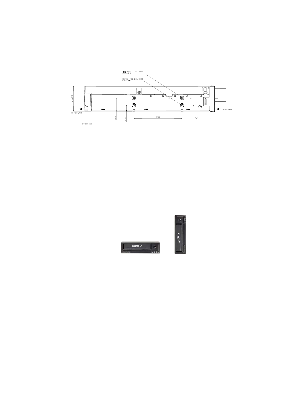
Mechanical Installation
For mechanical mounting specifications, please refer to Figure 1.
Allowed mounting position is either horizontal with the indicator LEDs to the
right, or vertical with the LEDs up.
The drive occupies a half-size 5.25-inch slot with standard holes for mounting
screws on both sides of the drive chassis and at the bottom of the drive.
Figure 1 Mounting specifications
Important!
Mounting screw
requirements
• Only M3 (metric) screws must be used for mounting the drive
• Maximum permitted screw penetration: 3.0 mm
• Minimum required screw penetration: 2.0 mm
• Screw torque, mounting screws: 0.5 Nm
• Screws are supplied with all the Tandberg 420LTO drive
variants
Do not use longer screws or higher screw torque
than specified!
Figure 2 Allowed mounting orie nt at i o n s
2
Page 3
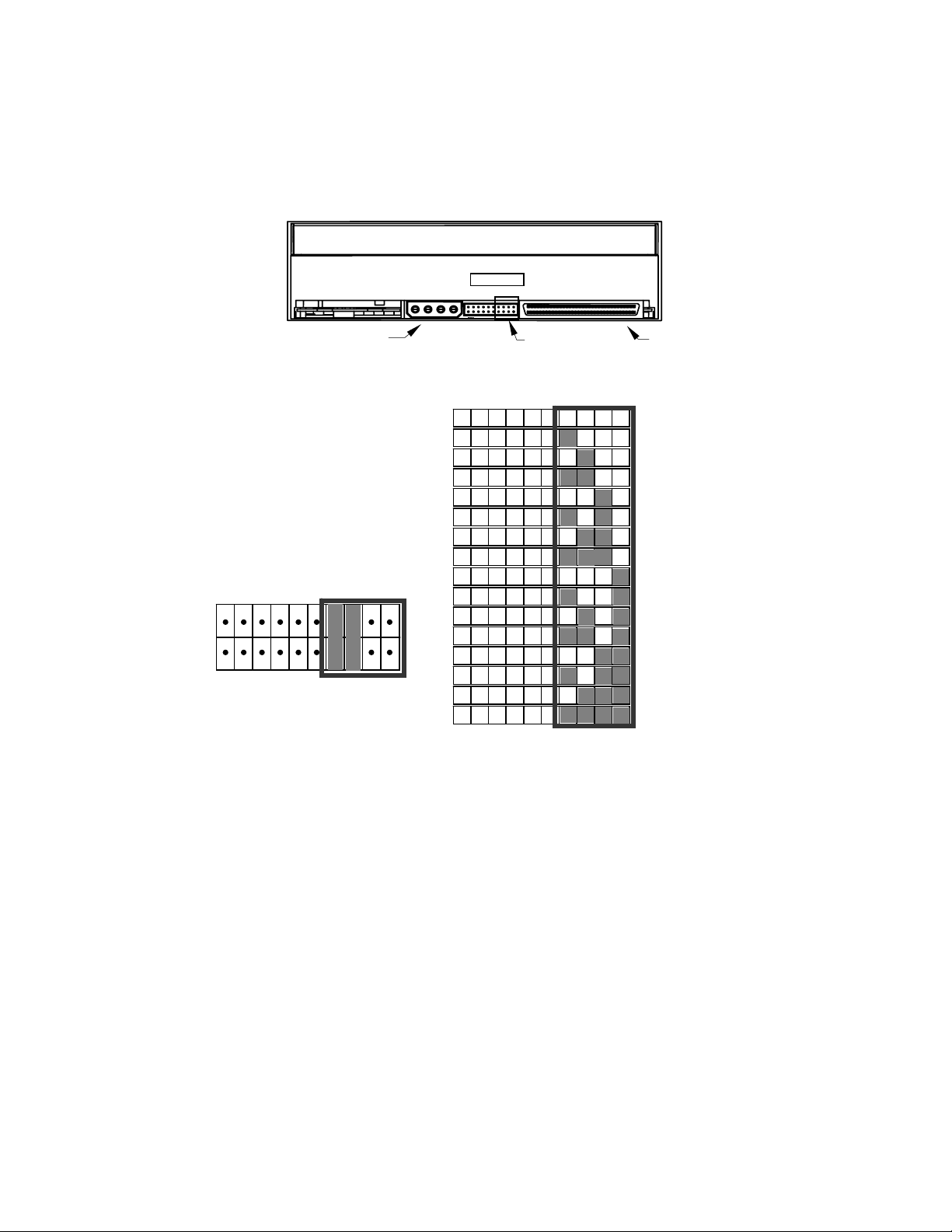
SCSI Identification
Make sure that the drive unit has the proper SCSI-ID before it is connected to a
computer system.
Refer to manuals for host computer and application software to obtain the correct
ID. For correct mounting of ID-jumpers at the rear of the drive, please refer to
Figure 3 and Table 1.
External drives have a thumb-wheel switch to set the SCSI-ID (see Figure 6).
Power Connector
Figure 3 Drive connectors
The factory default drive
number setting is SCSI ID = 2.
If the drive has to be set up
with a different unit number,
the straps (on the Service
Connector) have to be
connected according to
Table 1.
Example: SCSI ID = 3
Service Connector
SCSI Connector
SCSI ID=0
SCSI ID=1
SCSI ID=2
SCSI ID=3
SCSI ID=4
SCSI ID=5
SCSI ID=6
SCSI ID=7
SCSI ID=8
SCSI ID=9
SCSI ID=10
SCSI ID=11
SCSI ID=12
SCSI ID=13
SCSI ID=14
SCSI ID=15
Table 1 Service Connector strap settings
for SCSI ID (Dark = Strap mounted)
3
Page 4

SCSI Cable
Host
Internal Terminator Connector
Last SCSI Device
-
Figure 4 SCSI cable
• Internal SCSI-LVD/SE-cable with 5 co nnectors (Ordering no. 43 32 63)
• Internal, removable SCSI-LVD/SE-terminator (Ordering no. 43 20 53)
• External, removable SCSI-LVD/SE-terminator (Orderin g n o. 43 20 52)
• External SCSI 68HD/VHDCI 320MBs (Ordering no. 43 32 64)
10 cm
Termination
The SCSI-bus cable must be terminated in both ends according to SCSI
specifications. If the tape drive is the last device on the bus, the bus must be
terminated within 10 cm of the tape drive connection.
Tandberg 420LTO has a combined SCSI-LVD/SE interface embedded. The PC-98
Specification specifies that the termination of the SCSI-bus system is a part of the
SCSI-cable and not a part of the SCSI-device.
As a result, termination cannot be turned on or off directly on the tape drive itself.
For internal devices, a SCSI-cable with an integrated terminator or a separate
terminator applied to the end connector of the cable, 10 cm from the last device,
must be used.
External devices must be terminated with an external terminator on the last device
on the SCSI-bus.
Software Installation
For Software Application support and software drivers, please see
www.tandberg.com/ > SUPPORT > LTO Support and www.tandberg.com/ >
SUPPORT > Software Compatibility
For installation of Backup Application software, refer to the software vendor’s
software application user guide supplied with the software or on the software
vendor’s web.
4
Page 5

Front LED Indicators
Figure 5 Light Emitting Diodes (LED)
Drive State
LED-test.
The LEDs are turned ON one-by-one.
Power-On Self-Test starts in parallel
with the LED-test .
Cartridge not loaded. OFF OFF ON / OFF OFF
Cartridge loaded, no activity ON OFF ON / OFF OFF
Cartridge loaded, activity ON Flashing ON / OFF OFF
Cleaning OFF Flashing ON OFF
Cartridge loading or unloading OFF Flashing ON / OFF OFF
Unrecoverable drive failure ON / OFF OFF ON / OFF Flashing
Over temperature OFF OFF ON / OFF ON
Media Error (wrong, write protected or
harmed media)
READY LED
(Green left)
ON ON ON ON
OFF Flashing ON / OFF Flashing
ACTIVITY LED
(Green)
CLEAN LED
(Amber)
FAULT LED
(Amber right)
Table 2 Front LED behavior during normal operation
For a complete description of LED behavior see Tandber g 4 20LTO Reference
Manual.
5
Page 6

Media and Capacities
Drive Model Media Name Tape Length Capacity
Tandberg
420LTO
LTO Ultrium Generation 2 (Native format)
LTO Ultrium Generation 1 (Read/Write compatible)
609 m
609 m
(Native)
200 GByte
100 GByte
Table 3 Media alternatives
External Tabletop Enclosure
ON/OFF Switch
Cooling Fan SCSI_ID Switch
SCSI Interface Connectors Power Connector
Figure 6 External tabletop enclosure, rear side
Power Requirements
Tandberg 420LTO in external tabletop enclosure:
AC Input: 100 VAC / 0.6 A or 240 VAC / 0.3 A, 50-60 Hz
Tandberg 420LTO as standalone:
DC Input (typical operation): 5 VDC / 2.1 A, 12 VDC / 0.6 A
Heat Dissipation
Tandberg 420LTO as standalone:
Operating: 18 W
Sleep mode with cartridge inserted: 9 W
6
Page 7

Total customer satisfaction is of the utmost importance
to Tandberg Data.
We guarantee that this product left our premises defect free.
If you are not satisfied with the quality of this product,
please contact your distributor or the nearest
Tandberg Data office to have the problem solved!
For more documentation and information, please see our website
www.tandberg.com.
7
Page 8

Tandberg Data
International headquarters
Tandberg Data ASA, Kjelsåsveien 161, Oslo, P.O. Box 134 Kjelsås, N-0411 Oslo, Norway.
Tandberg Data GmbH, Feldstrasse 81, D-44141 Dortmund, Germany.
Tandberg Data S.A.S., 16/18 Ave. Morane-Saulnier, F-78941 Vélizy Cedex, France.
Fax: +33 1 34 65 02 89 (for technical support: 00800-07867243).
Tandberg Data (Asia) Pte. Ltd, 20 Bendemeer Road, #04-05 Cyberhub, Singapore 339914,
Tandberg Data (Japan) Inc., Eitaibashi Eco-Piazza Bldg. 8th floor 29-13, Shinkawa 1-chome,
Tandberg Data (UK) Ltd., Registered Office, High Street Redbourne, Herts AL3 7LW, UK
Specifications subject to change without notice. All trademarks are the property of their respective owners.
Tel: +47 22 18 90 90. Fax: +47 22 18 95 50.
www.tandberg.com
Worldwide subsidiaries
Inostor Inc., 13000 Gregg Street, Poway, CA 92064, U.S.A.
Tel: +1 858 726 0277. Fax: +1 858 726 0278.
Tel: +49 231 5436 0. Fax: +49 231 5436 111.
Tel: +33 1 39 26 01 01/00800-82632374.
Tel: +65 6396 0786. Fax: +65 6396 0787.
Chuo-ku Tokyo 104-033, Japan
Tel: +81 3 5566 2871. Fax: +81 3 5566 2875.
Tel: 00800-82632374. Fax: 00800-07867243.
©2005 Tandberg Data ASA. All Rights reserved.
Part No. 433261-01. February 2005.
 Loading...