

Page 1
TT Technical Information 7.09.2005
RS232 adapter
R-Link command
R-Link flag
RS232 control of SR1535.
The surround receiver SR1535R with software version 1.13 or higher is compatible to be controlled by
a connected control-system having a RS232 serial output port (PC, CRESTRON home automation
system etc.) through the RS232/R-Link interface adapter. With versions from 1.40 or higher there is
the additional possibility to receive status information from the SR1535R.
For details about connecting and operating the adapter see the user manual of the adapter
“UM_RS232_Adapt.doc”.
Settings for the RS232 interface of the control device are as follows:
Baud rate: 115.200
Data bits: 8
Stop bits: 1
Parity: none
Flow Control: none
T+A RS_232 Protocol
The R-series devices use the standard T+A RS232 command protocol as described in detail in the
documents “TA_RS232_protocol.doc” and “RS_232_Command_Codes.doc”.
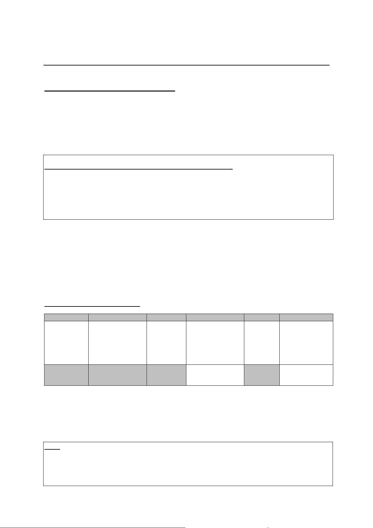
Format of the command telegrams
A command telegram to the R-system master device consists of 6 bytes. The complete telegram
should be sent without pauses between the bytes.
Example: SYSTEM_ON command
Byte 1 Byte 2 Byte 3 Byte 4 Byte 5 Byte 6
Telegram length
Address
(always 0x01)
0x01 0x03 0xC8 0x57 0x02 0x25
Byte 1, 2, 3, 5 : these bytes have the fixed values as shown in the table above for all R-system
Byte 4 : R-Link command according to the table of RCII commands
(R-Link address + R-Link
command + R-Link flag
byte = 0x03)
master devices
(see “RS_232_Command_Codes.doc”)
R-Link
Address
(0xC8=Amplifier/
master device
à see also note
below)
(here: SystemON = 0x57)
à see command table
“appendix 1”
byte
(always 0x02)
Check sum
= sum of bytes 1..5
mod. 0xFF
Byte 6 : check sum == (byte1+byte2+byte3+byte4+byte5) modulo 0xFF
Note:
The R-Link address 0xC8 is used for all standard amplifier commands.
There exist a few additional commands (system commands) for some special functions. For these
commands the address 0xC4 has to be used. At this time there are non of these relevant for surround
control.
Page 2
Format of the acknowledge (ACK) telegrams
milli-seconds after sending a command, there is either a
The R-System master device will process each received command telegram and it will send an
acknowledge telegram approx. 25...35 ms after receiving the command.
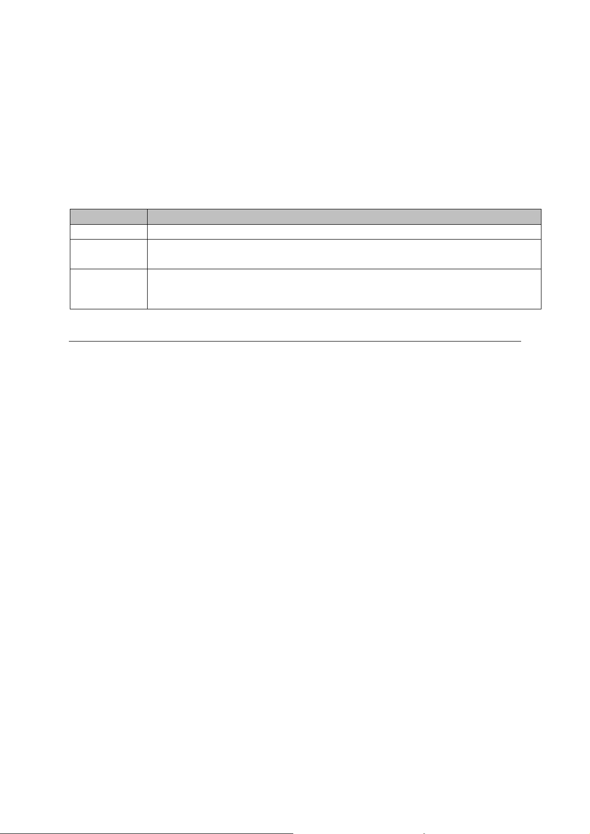
The ACK telegram consists of 2 bytes:
Byte 1 is the RS232 address of the command telegram received before (=byte 1 of the command
telegram = 0x01).
Byte 2 is the acknowledge byte. If this byte is equal to the check sum of the command telegram
(byte_6 of the command) then the command was received correctly. If byte_2 has a value different
from the check sum of the command, an error has occurred (see table below).
Format of the ACK telegram:
Byte 1 Byte 2
RS232 address ACK byte
0x01
After the ACK telegram, the master device is ready for the next command.
= check sum of command: command correctly received
= check sum –1: command ignored (system busy)
= check sum –2: command not executed
Note:
If no ACK telegram is received within 35
hardware problem (cable etc.) or the telegram is erroneous (wrong address, wrong check sum ....)
Special System Commands
Beginning with version 1.40 the SR1535R automatically pushes the status information after it has changed.
Additionally the status can be requested by sending the command 0x64 (Status_1) or 0x43 (Status_2) to the
RLink-address 0xC4 but normally this should not be necessary. We strongly recommend to keep the
number of status requests low to avoid unnecessary RLink-Bus load. The information given is different for each
device and has to be decoded and displayed individually. For further information see the user manual ‘Crestron
T+A Macro’.
Responses of the SR1535R are as follows:
Page 3
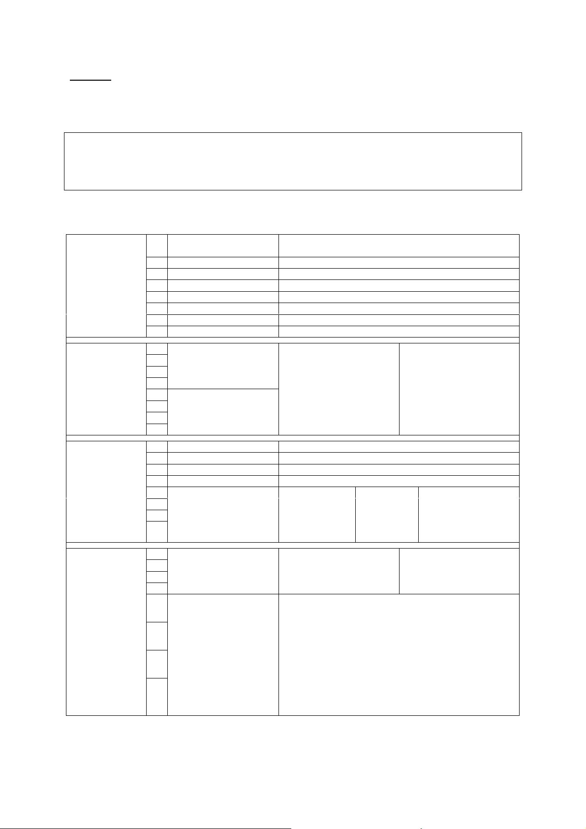
Status 1:
The STATUS_1 is automatically pushed by the SR1535R when any contained information has changed or the
command STATUS_1 was sent to the SR1535R. It is answered by a 9 byte long status telegram having the
following format:
0x01, 0x05, 0xC4, 0x64, Stat_Byte_1, Stat_Byte_2, Stat_Byte_3, Stat_Byte_4, Checksum
-----------------------------------|---------------------------------------------------------------------------|----------------HEADER (4) STATUS BYTES (4) CHK-SUM (1)
The 4 header bytes (0x01/0x05/0xC4/0x64) are constant.
The 4 status bytes are defined as follows:
Stat_Byte_1
Stat_Byte_2
Stat_Byte_3
b0 Protection 1:= Amplifier is in protection mode
(overload / overheat)
b1 Speaker_A 1:= speaker A output is ON
b2 Speaker_B 1:= speaker B output is ON
b3 Speaker_C 1:= speaker C output is ON
b4 Speaker_D 1:= speaker D output is ON
b5
b6 STANDBY 1:= System is in STANDBY
b7 ON 1:= System is ON
b0
Listen Source
(0...15)
b1
b2
b3
b4
Recording Source
(0...15)
b5
b6
b7
0:= not defined
1:= CD
2:= TUNER
3:= TAPE 1
4:= TAPE 2
5:= TV/Video
6:= AUX 1
7:= AUX 2
8:= AUX 3
9:= DVD
10:= STB
11:= VCR
12:= AUX/AV 1
13:= AUX/AV 2
14:= DBR (Digital Radio)
15:= not def. / future use
b0 LOUDness 1:= Loudness is ON
b1 FLAT 1:= FLAT is ON (= Tone defeat)
b2 DirectStereo 1:= High Quality stereo mode
b3
b4
SurroundMode (0...15) 0:= Surnd (5.1)
b5
b6
b7
1:= Stereo
2:= Mono
3:= Mono I
4:= Mono II
5:= Disco
6:= Hall
7:= Opera
8:= Arena
9:= Club
10:= Church
11:= MCH-Input
15:= Surnd EX/ES
(7.1)
Stat_Byte_4
b0
SourceFormat (0...4) 0:= analog
b1
b2
b3
b4
DecodingMode (0...10) 0:= None
b5
b6
b7
4:=AAC
1:= PCM
2:= Dolby Digital
3:= DTS
1:= Dolby Pro Logic II Movie Mode
2:= Dolby Pro Logic II Music Mode
3:= Dolby Pro Logic II Matrix Mode
4:= Dolby Pro Logic IIx Movie Mode
5:= Dolby Pro Logic IIx Music Mode
6:= Dolby Pro Logic IIx Matrix Mode
7:= Dolby Pro Logic IIx EX compatible Mode
8:= DTS Neo:6 Cinema Mode
9:= DTS Neo:6 Music Mode
10:= DTS ES
Page 4

Status 2:
The STATUS_2 is automatically pushed by the SR1535R when the volume has changed or the command
STATUS_2 was sent to the SR1535R. It is answered by a 7 byte long status telegram having the following
format:
0x01, 0x05, 0xC4, 0x43, Status_Byte_1, Status_Byte_2, Checksum
-----------------------------------|---------------------------------------------------------------------------|----------------HEADER (4) STATUS BYTES (2) CHK-SUM (1)
The 4 header bytes (0x01/0x05/0xC4/0x43) are constant.
The 2 status bytes are defined as follows:
Status_Byte_1
Stat_Byte_2
b0
Volume of main room
(0...63)
b1
b2
b3
b4
b5
b6
b7
b0
Volume of 2nd room
(0...63)
b1
b2
b3
b4
b5
b6
b7
Page 5

Appendix 1: List of Master (Amplifier) commands (Address 0xC8)
Command Command
Code (HEX)
System ON 0x57 Switch the master device ON
System Standby 0x77 Switch the system (master and source devices) to STANDBY
System OFF 0x7A Switch the system completely OFF
Volume + Tone Control
VOL_PLUS 0x00
VOL_MINUS 0x20
VOL_B_PLUS 0x4E
VOL_B_MINUS 0x6E
Balance_L 0x38 one step to the left
Balance_R 0x18 one step to the right
LOUDness 0x2C x
LOUDness ON 0x75
LOUDness OFF 0x55
FLAT 0x0C x
FLAT ON 0x7B tone control defeat
FLAT OFF 0x47 tone control on
Speaker Control
SPKR 0x13 x
Speaker_A ON 0x68 Speaker A output ON
Speaker_A OFF 0x48 Speaker A output OFF
Hint: Although the SR1535R has no Speaker B/C/D outputs itself it reacts to the commands and switches
external amps. When 2nd room functions are enabled the speakers C/D are mapped to 2nd room speakers
A/B (2nd room amp needs special software).
Speaker_B ON 0x58 Speaker B output ON
Speaker_B OFF 0x78 Speaker B output OFF
Speaker_C ON 0x6C Speaker C output ON
Speaker_C OFF 0x4C Speaker C output OFF
Speaker_D ON 0x5C Speaker D output ON
Speaker_D OFF 0x7C Speaker D output OFF
Surround control
Surround EX/ES 0x6F Surround EX/ES mode
Surround 5.1 0x6D Surround 5.1 mode
Stereo 0x4D Stereo mode
Mono 0x5D Mono mode
Mono I 0x3D use left channel for Mono
Mono II 0x53 use right channel for Mono
Disco 0x63 SoundField: Disco
Hall 0x76 SoundField: Hall
Opera 0x7E SoundField: Opera
Arena 0x71 SoundField: Arena
Club 0x69 SoundField: Club
Church 0x79 SoundField: Church
MCH-Input 0x67 Use Multichannel-Input if assigned to active source
SURND 0x37 x toggle between Surround- and Preamp-Mode
PRE 0x0E switch to HQ-Stereo-Mode
toggle Remark
Performs 1 volume step of the main room volume.
Hint: Repeat these commands for continuous volume
increase/decrease (command repetition rate = 100...110 ms)
Performs 1 volume step of the 2nd room volume (if enabled)
Hint: Repeat these commands for continuous volume
increase/decrease (command repetition rate = 100...110 ms)
Switches the speaker outputs insequence ON and OFF:
A -> B -> A+B -> OFF
Hint: better use the “discrete” Speaker_A/Speaker_B ON +
OFF commands
Page 6

Source selection (Group commands)
CD 0x23 x CD ßà DVD
Tuner 0x17 Tuner
Tape 0x35 Tape
DAT/Tape-2 0x15 x VCR-1 ßà VCR-2
Video/TV 0x07 x TV ßà STB
AUX 0x3D x AUX/P à AUX-AV-1 à AUX-AV-2 ...
MC/Aux-2 0x27 AUX/P
MM/Aux-3 0x1D x AUX-AV-1 ßà AUX-AV-2
Source selection (discrete commands)
SRC_CD 0x45 CD
SRC_Tuner 0x46 Tuner
SRC_Tape-1 0x49 Tape
SRC_TV 0x59 TV
SRC_Aux-2 0x65 AUX/P
SRC_Aux-3 0x61 CAM
SRC_DVD 0x42 DVD
SRC_STB 0x62 STB
SRC_VCR-1 0x52 VCR-1
SRC_Aux-AV-1 0x72 Aux-AV-1
SRC_Aux-AV-2 0x4A Aux-AV-2
SRC_VCR-2 0x66 VCR-2
Main / Config - Menu
AMP Menu (short) 0x40 Open Main Menu
AMP Menu (long) 0x41 Open Configuration Menu
Close AMP Menu 0x60 Close active Menu (Main or Configuration)
Hint: The Menu navigation is done by the keys NEXT (0x34), PREV (0x2A), FF (0x25), RW (0x1A) and
OK (0x26) which are normally forwarded to the active source device.
Page 7

Revision history:
01.09.2005 release
07.09.2005 added STATUS_BYTE_4 – DecodingMode – Message “DTS ES” for value=10. (without this the DTS ES
operation is falsely indicated as “DTS” “PLIIx...”) (supported by SR1535R V1.41 and later).
 Loading...