

Page 1

Bedienungsanleitung
Operating Instructions
MRA
V 1.0 Bestell-Nr. / Order No. 9103-0287
Page 2

2
Page 3

Seite / Page
Deutsch 4
English 14
3
Page 4

Die
R-Anlage eignet sich in Kombination mit einem
QED
Multiroom-Controller hervorragend zum Aufbau
eines hochwertigen Multiroom-Systems. QED bietet mit
Systemline 4.3 und Commander 4.4, zwei Systemvarianten, die sich für die Kombination mit Anlagen
eignen. Die Verteilung von Video Signalen (DVD, SetTopBox etc.) ist über Erweiterungen des QED Systems
ebenfalls möglich.
Die QED Multiroom Controller werden über den
MRA
Baustein direkt an die
des
Systems angekoppelt. Umständliche Ankopplungen über Infrarotschnittstellen werden bei der
/ QED Lösung nicht benutzt.
R
LINK
Steuerschnittstelle
Systemaufbau, Systemkomponenten
R-Anlage
Bei der
reoversion oder um ein voll ausgebautes Surroundsystem handeln. Bei einer
kann im Hauptraum in Surround gehört werden, in den
Nebenräumen stehen die angeschlossenen Quellgeräte
für Stereowiedergabe zur Verfügung.
R-Anlage kann es sich um eine reine Ste-
Surround Kombination
Wichtige Hinweise
Der Tuner muss ein „stand-alone“ Gerät sein. Es muss
also ein
Receiver (R 1220 R, R 1520 R oder SR 1510 R) sind
nicht geeignet.
Als Master können
PA 1530 R
eine
rüstet bestellt werden. (Die Sondersoftware ist für ältere
Geräte auch als Upgrade erhältlich.)
Neben dem Tuner können andere
wie z. B. CD-Spieler (
Spieler (
räte benutzt werden.
T 1210 R
Sondersoftware
DVD 1210 R, DVD 1230 R
als Tuner verwendet werden.
P 1220 R
verwendet werden. Das Mastergerät benötigt
und kann entsprechend ausge-
CD 1230 R, CD 1240 R
oder
PA 1230 R
R
) als weitere Quellge-
oder
LINK
Geräte
) oder DVD
QED 4.3 System
Mit dem 4.3 Controller können
und DVD-Spieler in ihren Grundfunktionen (Einschalten,
Senderwahl, Titelsprung etc.) gesteuert werden. Auch die
DVD-Spieler
Audio-Quelle (CD Betrieb) bedient werden. Eine DVD
kann gestartet, pausiert und gestoppt werden, ebenso ist
eine einfache Navigation (Tracksprünge, Vorlauf, Rücklauf) möglich. Für weitergehende DVD Funktionen (DiscMenüs, Cursorfunktion etc.) ist das größere 4.4 System
erforderlich.
Die Bedienung aus dem Nebenraum erfolgt über die
QED Bedienpanels (DMS / KMS / CMS) oder die QED
Fernbedienung RHS 3.
DVD 1210 R
Tuner, CD-Spieler,
DVD 1230 R
und
können als
QED 4.4 System
Der QED Commander (4.4) bietet über die RHS 4 Fernbedienung die Unterstützung zusätzlicher Steuermöglichkeiten wie z. B. Cursor-Funktionen, direkte Titel- / Stationseingabe über 10er Tastatur etc.
Die Bedienung aus dem Nebenraum erfolgt über die
QED Bedienpanels (DMS / KMS / CMS / NMS) oder die
QED Fernbedienung RHS 4.
MRA
Der
verterbaustein, der Steuerbefehle der
systeme entgegennimmt und in
mandos umsetzt. Mit dem
mit einer R
der
werden.
Multiroombetrieb mit zwei
MRA
R-Serie in das Multiroom-System integriert
ist ein microprozessor-gesteuerter Kon-
QED
Multiroom-
LINK
R
MRA
können alle aktuellen,
LINK
- Schnittstelle ausgerüsteten Quellgeräte
Steuerkom-
Tunern
Es können im Multiroomsystem zwei Tuner
eingesetzt werden. Der zusätzliche zweite Tuner benötigt
eine Sondersoftware und kann entsprechend ausgestattet bestellt werden.
T 1210 R
4
Page 5

Hinweise zum Betrieb
Die Bedienung der
räumen ist im Detail in der Bedienungsanleitung des
QED Multiroomsystems beschrieben. Nachfolgend geben
wir noch einige ergänzende Hinweise zum Betrieb des
Systems:
Komponenten aus den Neben-
Ausschalten / Standby
Das QED System kann durch einen kurzen Druck auf
den STBY (RHS-3) bzw. EIN/AUS Taster (RHS-4) in
Standby geschaltet werden.
Ein langer Tastendruck schaltet das System ganz aus
(Meldung „OFF“ erscheint im Display des DMS Panels).
Hinweis:
Im STANDBY Zustand des QED Multiroomcontrollers
bleiben die Quellgeräte eingeschaltet. Zum Abschalten
der Quellgeräte schalten Sie den QED Controller bitte
ganz aus (Meldung „OFF“ auf der DMS Anzeige abwarten).
Besonderheiten beim QED S 4.3 System
Der Tuner im Multiroomsystem
Der Tuner hat im Multiroomsystem eine zentrale Bedeutung. Er ist die sicherlich die am meisten genutzte Multiroom-Quelle und er wird für besondere Aufgaben z.B.
zum Wecken in Verbindung mit der Weckfunktion des
QED Systems gebraucht. Der
grundsätzlich immer eingeschaltet, wenn das Multiroomsystem aktiviert wird. Er bleibt auch während der gesamten Einschaltdauer des Multiroomsystems eingeschaltet. Wird der Tuner von Hand am Netzschalter des
Gerätes ausgeschaltet, so wird er automatisch vom MRA
wieder eingeschaltet. Ein versehentliches Abschalten des
Tuners und damit eine eventuelle Nichtfunktion des Weckers wird damit vermieden.
Tuner wird daher
Zweiter Tuner am R
Der zweite Tuner wird mit der Quellentaste 3
(TAPE/SAT) selektiert.
Die Tasten -<< bzw. >>+ der Fernbedienung RHS 3
wechseln den Sender.
Die Taste STOP ist ohne Funktion
LINK
Ausgang 3 des MRA
Zweiter Tuner am R
Der zweite Tuner kann alternativ auch am Ausgang 4 des
MRA angeschlossen werden.
Er wird dann mit der Quellentaste 4 (VID/DVD) selektiert.
Die Tasten -CHNL bzw. CHNL+ der Fernbedienung
RHS 3 wechseln den Sender.
Die Tasten STOP, PAUSE, -<< bzw. >>+ der Fernbedienung RHS 3 sind ohne Funktion.
LINK
Ausgang 4 des MRA
5
Page 6
Installation
Die Installation des Systems ist sehr einfach: QED Controller und
Konverterbaustein miteinander verbunden (s. Bild unten).
Die benötigten Kabel gehören zum Lieferumfang des
MRA
bereit. Im Falle des größeren QED 4.4 Controllers werden zusätzlich noch die
(Diskette liegt dem
den Controller geladen.
Anlage werden über den „
/ QED 4.3 System ist dann betriebs-
. Das
Fernbedienungscodes
MRA
bei) vom Laptop via RS232 in
MRA
Im Folgenden wird der Anschluss des
“
den QED Controller beschrieben. Die Installation und
Inbetriebnahme des QED Multiroom Systems ist in der
Bedienungsanleitung des QED Systems detailliert beschrieben.
Systems an
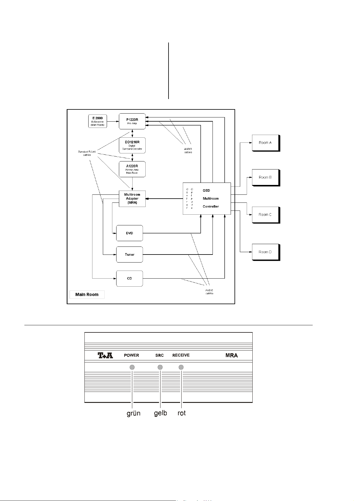
Schematischer Aufbau Multiroomsystem
Frontansicht Multiroom-Adapter MRA
LED grün: Betriebsspannung vom
LED gelb: Systemline Controller eingeschaltet oder Standby
LED rot: a) Flackern bei Nebenraumbedienung: korrekter Empfang von RC5 Befehlen (nur bei 4.3 System)
b) Blinken im 10 Sekunden Takt:
Quellgerät liegt an
MRA
Aktivitätsanzeige
6
Page 7

Anschluss und Inbetriebnahme
Zur Installation des Systems gehen Sie am besten
schrittweise wie unten beschrieben vor:
1.) Installieren Sie zunächst das
den Bedienungsanleitungen beschrieben und nehmen es in Betrieb. Überprüfen Sie, ob die Steuerung
und Fernbedienung aller Komponenten funktioniert.
2.) Trennen Sie die R
Quellgeräten auf und schließen Sie diese an die
R
LINK
Ausgänge des
mäß den Anschlussbildern her. Schließen Sie die Geräte bitte wie folgt an die Ausgänge des
TUNER an
CD an
TUNER 2 (*) an
DVD an R
(*) Sondersoftware erforderlich
3.) Verbinden Sie die „SOURCE“ Buchse des
der „RC-IN“ Buchse eines
des Tuners). Kontrollieren Sie, dass die grüne Kontroll-LED am
dung hergestellt ist. Das Quellgerät muss natürlich mit dem Netz verbunden sein.
LINK
MRA
aufleuchtet, sobald diese Verbin-
R-System wie in
Verbindungen zwischen den
MRA
Konverterbausteins ge-
MRA
an:
R
LINK
Buchse 1
R
LINK
Buchse 2
R
LINK
Buchse 3
LINK
Buchse 4
MRA
mit
Quellgerätes (z. B.
Hinweis:
Die grüne LED muss leuchten, unabhängig davon, ob
das Quellgerät ein- oder ausgeschaltet ist.
4.) Schalten Sie nun probeweise die
Überprüfen Sie, ob Steuerung und Fernbedienung
aller Komponenten funktionieren (wie unter 1.).
5.) Anschluss an das 4.3 System
Installieren Sie das QED System wie in der QED Anleitung beschrieben und stellen Sie die Audio Verbindungen zwischen Quellgeräten, Systemline Controller
Verstärker her.
und
Anlage ein.
Wichtiger Hinweis:
Der 4.3 Controller muss für alle zu steuernden
Quellgeräte auf RC5 Betrieb eingestellt sein. Bitte
kontrollieren Sie diese Einstellung.
Stellen Sie nun die RC5 Verbindung (Cinch-Kabel)
zum Systemline Controller her und verbinden Sie das
Steckernetzteil mit dem geschalteten Netzausgang
des Controllers (s. Anschlussbild 4.3 Controller).
Schließen Sie den Ausgang des Steckernetzteiles an
den TRIGGER Eingang des
Nachdem Sie die Anschlüsse hergestellt haben,
schalten Sie den Systemline Controller ein und aktivieren Sie eine Hörzone. Sobald eine der Hörzonen
aktiv wird, muss die gelbe (mittlere) Kontroll-LED des
MRA
aufleuchten. Sofern ein
sen ist, sollte dieser nach einigen Sekunden einschalten. Durch Druck auf eine der anderen Quellentasten des QED Systems (z. B. CD) können die ande-
Quellgeräte eingeschaltet werden.
ren
MRA
an.
Tuner angeschlos-
Jeder Bedienvorgang (Tastendruck) am QED System
für eines der
dass die rote (rechte) Kontroll-LED am
aufblinkt. Das Aufblinken dient der Funktionskontrolle
und signalisiert den Empfang von Steuerbefehlen für
System.
das
Kontrollieren Sie, ob sich alle an den
schlossenen
bedienen lassen und überprüfen Sie, ob die Tonwiedergabe funktioniert. Das Multiroom-System ist danach funktionsfähig und einsatzbereit.
6.) Anschluss an das 4.4 System (QED Commander)
Installieren Sie das QED System wie in der QED Anleitung beschrieben und stellen Sie die Audio Verbindungen zwischen Quellgeräten, Systemline Controller
Verstärker her.
und
Stellen Sie die Verbindungen (Kabel mit Klinkenstecker) zwischen QED Commander und
im Anschlussbild „QED S4.4 (QED Commander)“ angegeben. Achten Sie bitte darauf immer gleichnamige
Anschlüsse miteinander zu verbinden, also
TX1 mit TX1 – für die Quelle 1 = TUNER
TX2 mit TX2 – für die Quelle 2 = CD
usw.
Verbinden Sie nun das Steckernetzteil mit dem geschalteten Netzausgang des Controllers (s. Anschlussbild) und schließen Sie den Ausgang des Steckernetzteiles an den TRIGGER Eingang des
an.
Laden Sie nun die
schlossenen Geräte vom PC in den Commander. (s. QED Betriebsanleitung).
Quellgeräte sollte dazu führen,
MRA
MRA
ange-
Quellgeräte vom QED System aus
MRA
her, wie
Steuercodes für alle ange-
Hinweis:
Die Steuercodes für
der dem
Schalten Sie den Systemline Controller ein und aktivieren Sie eine Hörzone. Sobald eine der Hörzonen
aktiv wird, muss die gelbe (mittlere) Kontroll-LED des
MRA
sen ist, sollte dieser nach einigen Sekunden einschalten. Durch Druck auf eine der anderen Quellentasten des QED Systems (z. B. CD) können die anderen
MRA
aufleuchten. Sofern ein
Quellgeräte eingeschaltet werden.
Quellgeräte finden Sie auf
beiliegenden Diskette.
Tuner angeschlos-
Hinweis:
Beim 4.4 System leuchtet die rote (rechte) KontrollLED am
Sofern das QED System eingeschaltet oder im
Standby ist, blinkt die rote LED in Abständen von ca.
10 Sekunden kurz auf.
Kontrollieren Sie, ob sich alle an den
schlossenen
bedienen lassen und überprüfen Sie, ob die Tonwiedergabe funktioniert. Das Multiroom-System ist danach funktionsfähig und einsatzbereit.
MRA
bei Bedienvorgängen
Quellgeräte vom QED System aus
nicht
auf!
MRA
ange-
kurz
MRA
7
Page 8

Anschluss an das QED S4.3 System
(Audio-Verkabelung nicht dargestellt, s. QED Installationsanleitung)
8
Page 9

Anschluss an das QED S4.4 System (QED Commander)
(Audio-Verkabelung nicht dargestellt, s. QED Installationsanleitung)
9
Page 10

Betriebsstörungen
Symptom Ursache Abhilfe
Quellgeräte schalten nicht ein oder können nicht vom QED System bedient
werden
grüne Kontroll-LED am
MRA
leuchtet nicht
Grüne LED am
leuchtet, gelbe Kontroll-LED
MRA
am
QED 4.3 System:
Grüne und gelbe LED am
MRA
troll-LED am
nicht bei Bedienung am
QED System (rote LED
blinkt nur regelmäßig im
10 sek. Takt)
QED 4.3 System:
Grüne und gelbe LED am
MRA
troll-LED am
bei Bedienung am QED
System
QED 4.4 System:
Grüne und gelbe LED am
MRA
leuchtet nicht
leuchten, rote Kon-
MRA
leuchten, rote Kon-
MRA
leuchten
MRA
flackert
flackert
Kabel zwischen „RC-IN“ Buchse eines Quellge-
LINK
LINK
LINK
LINK
MRA
-OUT“
“ Ein-
-OUT“
“ Ein-
rätes und dem „SOURCE“ Eingang des
nicht vorhanden oder nicht fest eingesteckt
a) QED System nicht eingeschaltet QED System einschalten, mit
b) Steckernetzteil am Netzausgang des QED
Controllers oder am TRIGGER Eingang des
MRA
nicht angeschlossen
a) Kabelverbindung zwischen „RC5“ Buchse
des QED Controllers und dem „RC5“ Eingang des
fest eingesteckt
b) QED Controller nicht auf RC5 Codes einge-
stellt
a) Kabelverbindung zwischen „R
Buchse des
gang des Quellgerätes nicht vorhanden oder nicht fest eingesteckt
b) Software des
Multiroom-Betrieb eingerichtet
a) Kabelverbindung zwischen „TX1 .... TX4“
Buchse des QED Controllers und dem entsprechenden „TX1 ... TX4“ Eingang des
MRA
steckt
b) Kabelverbindung zwischen „R
Buchse des
gang des Quellgerätes nicht vorhanden oder nicht fest eingesteckt
c) Software des
Multiroom-Betrieb eingerichtet
MRA
nicht vorhanden oder nicht
MRA
und dem „R
Quellgerätes nicht für
nicht vorhanden oder nicht fest einge-
MRA
und dem „R
Quellgerätes nicht für
Kabelverbindung herstellen, Stecker auf festen Sitz kontrollieren
Gerätetaster (Tuner, CD, Tape /
SAT, DVD) ein Quellgerät aktivieren
Netzteil anschließen, Stecker auf
festen Sitz kontrollieren
Kabelverbindung herstellen, Stecker auf festen Sitz kontrollieren
Stellen Sie den QED Controller für
Quellgeräte auf RC5 (s.
alle
Anleitung des QED Controllers)
Kabelverbindung herstellen, Stecker auf festen Sitz kontrollieren
Multiroom-taugliche Software im
Quellgerät installieren *)
Kabelverbindung herstellen, Stecker auf festen Sitz kontrollieren
Kabelverbindung herstellen, Stecker auf festen Sitz kontrollieren
Multiroom-taugliche Software im
Quellgerät installieren )*
Quellgeräte können nicht vom
grüne Kontroll-LED am
MRA
leuchtet
a) Kabel zwischen „R
ters und dem R
(Amp)“ des MRA nicht vorhanden oder nicht
fest eingesteckt
b) Kabelverbindung zwischen „R
Buchse des
gang des Quellgerätes nicht vorhanden oder nicht fest eingesteckt
System bedient werden
LINK
LINK
MRA
und dem „R
Buchse des Mas-
Anschluss „MASTER
LINK
-OUT“
LINK
“ Ein-
10
Kabelverbindung herstellen, Stecker auf festen Sitz kontrollieren
Kabelverbindung herstellen, Stecker auf festen Sitz kontrollieren
Page 11

Quellgeräte schalten ab
gelbe LED am
tet, das Abschalten geschieht beim Betätigen der
ON/OFF Taste der
Fernbedienung im Hauptraum oder beim Ausschalten des
(Vor- bzw. Vollverstärker)
Mastergerätes
Sämtliche
MRA
leuch-
Quellgeräte schalten nicht ab
Software des Mastergerätes nicht für Multiroom-Betrieb eingerichtet
, obwohl sie in einem Nebenraum in Benutzung sind
Multiroom-taugliche Software im
Mastergerät installieren (kann
Service geordert wer-
beim
den) *)
Hinweis:
Quellgeräte schalten nur ab, wenn Hauptraumanlage
gelbe Kontroll-LED am
MRA
leuchtet
QED Controller nicht abgeschaltet sondern in
STANDBY
QED Controller ausgeschaltet sind!
und
QED Controller ganz ausschalten:
STANDBY bzw. EIN/AUS Taste
so lange gedrückt halten, bis QED
Controller komplett abschaltet.
Tuner schaltet ein, obwohl nicht benutzt
Der Tuner als wichtigste Quelle des Multiroom
Systems wird grundsätzlich eingeschaltet, wenn
eine Zone des Multiroom Systems aktiv ist.
kein Fehler, normales Systemverhalten
Tuner Presets oberhalb Preset-Nummer 8 können nicht angewählt werden
nur bei QED 4.3 System
Beim QED 4.3 System werden nur die ersten
8 Presets des Tuners unterstützt
Die wichtigsten Sender auf Preset-Plätzen 1 ... 8 speichern oder
QED 4.4 System verwenden
Bedienung der Quellgeräte aus dem Hauptraum gestört
LINK
Quellgeräte lassen sich vom
Hauptraum aus nicht mehr
bedienen
gelegentlich wird ein Fernbedienungs-Tastendruck im
Hauptraum nicht ausgeführt
Bei Betrieb mit 2
Kabel zwischen „R
raumverstärker- und Decoderanlage (MASTER)
und dem „MASTER-AMP“ Eingang des
nicht vorhanden oder nicht fest eingesteckt
Das System kann nur einen Bedienvorgang zur
gleichen Zeit ausführen. - Bei gleichzeitiger
Bedienung eines oder mehrerer Quellgeräte
aus dem Hauptraum und einem Nebenraum hat
die Nebenraumbedienung Vorrang.
Tunern:
beide Tuner reagieren gleichzeitig bei Bedienung am
Der zweite Tuner (am R
angeschlossen) ist nicht mit der notwendigen
Sondersoftware ausgerüstet
*) Für die Integration in ein Multiroomsystem benötigen
T 1210 R
CD 1230 R
DVD 1210 R
DVD 1230 R
: größer V 1.03
CD 1240 R
/
: größer V 2.20
: alle Versionen geeignet
: größer V 4.20
“ Buchse der Haupt-
MRA
System
LINK
Out 3 des MRA
Quellgeräte folgende Software-Versionsnummer:
Kabelverbindung herstellen, Stecker auf festen Sitz kontrollieren
Taste im Hauptraum erneut drücken
Tuner mit Sondersoftware als
Zweittuner verwenden
Bei Master-Geräten muss folgende Anforderung an die Software-Versionsnummern erfüllt sein.
P 1220 R
Die Software-Versionsnummer ist auf dem Kontroll-Zertifikat des Gerätes angegeben.
PA 1230 R
/
PA 1530 R
/
: größer V 1.40
11
Page 12

12
Page 13

English
13
Page 14

The
R-system forms a superb basis for a high-
quality multi-room system in conjunction with a
Multi-room Controller. QED offers two system variants in
the Systemline 4.3 and Commander 4.4, both of which
are suitable for combination with equipment. Video
signal distribution (DVD, set-top box etc.) is also possible
by adding expansion units to the QED system.
QED
The QED Multi-room Controller is coupled to the R
control interface of the
module. The
plex infra-red interfaces.
/ QED solution does not include com-
System arrangement, system components
R-system
The
R-system may be either a pure stereo ar-
rangement or a fully expanded surround system. If a
surround combination is set up in the main room, surround sound can be heard in that room; in the adjacent
rooms the source devices connected to the system provide stereo sound.
Important notes
The tuner must be a „stand-alone“ device, i.e. a
tuner must be used.
Receivers (R 1220 R, R 1520 R or SR 1510 R) are not
suitable.
T 1210 R
QED 4.3 System
The 4.3 controller can be used to control the basic functions of a
on, station select, skip track etc.). The
DVD 1230 R
sources (CD mode) within the system. DVDs can be
started, paused and stopped, and simple navigation (skip
track, fast forward, rewind) is also possible. For more
sophisticated DVD functions (disc menus, cursor function
etc.) the larger 4.4 system is required.
The system is controlled from an adjacent room using
QED control panels (DMS / KMS / CMS) or the QED
RHS 3 remote control unit.
tuner, CD player and DVD player (power
DVD players can also be operated as audio
system via the
DVD 1210 R
LINK
MRA
and
The Master unit should be a
PA 1530 R
and can be ordered with the appropriate upgrade. (The
special software is also available as an upgrade for older
units.)
Other
CD 1230 R, CD 1240 R
(
DVD 1230 R
addition to the tuner.
. The Master unit requires
LINK
R
) can also be used as source devices in
units such as a CD player
P 1220 R
) or DVD player (
PA 1230 R
or
special software
DVD 1210 R
or
MRA
The
module which picks up the control commands of the
multi-room system and converts them into
control commands. The
any current
an
MRA
R
LINK
is a micro-processor controlled converter
MRA
R-series source device equipped with
interface into a multi-room system.
QED
R
can be used to integrate
LINK
Multi-room operation with two
tuners
,
QED 4.4 System
The QED Commander (4.4) supports additional control
functions such as cursor control, direct track / station
input via numeric keypad etc., using the RHS 4 remote
,
control handset.
The system is controlled from an adjacent room using
QED control panels (DMS / KMS / CMS / NMS) or the
QED RHS 4 remote control unit.
It is also possible to use two
case the second tuner must feature special software, and
can be ordered with the software already installed.
T 1210 R
tuners. In this
14
Page 15

Notes on using the system
The operating instructions supplied with the QED Multiroom system describe in detail the method of operating
the
system components from an adjacent room.
This section includes a few supplementary notes on
operating the system:
Switching off / Stand-by
A short press on the STBY (RHS-3) or ON/OFF button
(RHS-4) switches the QED system to Stand-by mode.
Holding the button pressed in switches the system off
completely („OFF“ message appears on the DMS panel
screen).
Note:
When the QED Multi-room Controller is in STAND-BY
mode the source devices remain switched on. To switch
off the source devices it is necessary to switch the QED
Controller off completely (wait until the „OFF“ message
appears on the DMS screen).
Special features of the QED S 4.3 system
The tuner in a multi-room system
The tuner assumes central importance in a multi-room
system. It is certainly the most commonly used multiroom source device, and is also used for special purposes such as an alarm clock, in conjunction with the
alarm function of the QED system. The
portance is reflected in the fact that it is always switched
on if the multi-room system is active, and it also remains
on during the whole period that the multi-room system is
switched on. If you switch off the tuner manually at the
mains switch, the MRA automatically switches it back on
again. This is designed to avoid accidentally switching off
the tuner, which would prevent the alarm system working.
tuner’s im-
Second tuner connected to R
LINK
output 3 of
the MRA
The second tuner is selected by pressing source button 3
(TAPE/SAT).
Use the buttons -<< and >>+ on the RHS 3 remote control handset to change the station.
The STOP button has no function.
Second tuner connected to R
LINK
output 4 of
the MRA
Alternatively the second tuner can be connected to output 4 of the MRA.
It is then selected using source button 4 (VID/DVD).
Use the buttons -CHNL and CHNL+ on the RHS 3 remote control handset to change the station.
The buttons STOP, PAUSE -<< and >>+ on the RHS 3
remote control handset have no function.
15
Page 16

Installation
Installing the system is very simple: the QED controller
and
system are connected using the „
converter module (see diagram below), using the cables
included with the
then immediately ready for use. If the larger QED
4.4 controller is selected, it is also necessary to load the
remote control codes into the controller from a laptop using the RS232 ports (diskette supplied with the
MRA
).
MRA
/ QED 4.3 system is
. The
MRA
The following section describes how to connect a
“
system to the QED controller. The operating instructions
supplied with the QED system describe in detail how to
install and use the QED Multi-room system.
Schematic diagram of multi-room system
Front view of MRA Multi-Room Adapter
Green LED: Operating voltage of
Yellow LED: Systemline Controller switched on or in Stand-by mode
Red LED: a) Flickers when operated from adjacent room: RC5 commands being picked up correctly (4.3 system only)
b) Flashes at 10-second intervals:
source device present
MRA
activity indicator
16
Page 17

Connections, using the system for the first time
The best method of installing the system is to follow the
step-by-step procedure described below:
1.) First install the
standard operating instructions, and switch it on.
Check that all the components work properly, and respond correctly to remote control commands.
2.) Disconnect the R
source devices, and connect them to the R
puts on the
wiring diagrams. Connect the equipment to the
outputs as follows:
TUNER to
CD to
TUNER 2 (*) to
DVD to R
(*) special software required
3.) Connect the „SOURCE“ socket of the
„RC-IN“ socket of one of your
(e.g. the tuner). Check that the green monitor LED
MRA
on the
made. Naturally, the source device must be
connected to the mains supply.
R-system as described in the
LINK
connections between the
LINK
out-
MRA
converter module as shown in the
MRA
R
LINK
socket 1
R
LINK
socket 2
R
LINK
socket 3
LINK
socket 4
MRA
to the
source devices
lights up as soon as this connection is
Note:
The green LED should light up whether the source
device is switched on or off.
4.) Now switch on the
tions: check that all the components work properly
and respond correctly to remote control commands
(as under 1.).
system to check the connec-
Every time you press a button on the QED system to
send a command to one of the
the red (right) monitor LED on the
briefly. The flashing confirms that the unit is working
properly, and indicates that the control command for
system has been picked up.
the
Check that you can use the QED system to control all
source devices connected to the
the
check that the system actually produces sound. The
multi-room system is now set up correctly, and is
ready for use.
6.) Connecting to the 4.4 system (QED Commander)
Install the QED system as described in the QED instructions, and complete the audio connections between source devices, Systemline Controller and
amplifier.
Complete the connections (cables terminating in barrel plugs) between the QED Commander and the
MRA
, as shown in the wiring diagram entitled „QED
S4.4 (QED Commander)“. Please take care always to
connect the terminals of the same name, i.e.
TX1 to TX1 – for source 1 = TUNER
TX2 to TX2 – for source 2 = CD
etc.
Connect the mains PSU to the switched mains output
of the Controller (see wiring diagram), and connect
the output of the mains PSU to the
marked TRIGGER.
Load the
devices into the Commander from a PC (see QED
operating instructions).
control codes for all connected
source devices,
MRA
should flash
MRA
MRA
input socket
, and
5.) Connecting to the 4.3 system
Install the QED system as described in the QED instructions, and complete the audio connections between source devices, Systemline Controller and
amplifier.
Important note:
The 4.3 Controller must be set to RC5 mode for all
source devices which are to be controlled.
Please check this setting.
Now complete the RC5 connection (Cinch cable) to
the Systemline Controller, and connect the mains
PSU to the switched mains output of the Controller
(see Controller wiring diagram 4.3).
Connect the output of the mains PSU to the input
socket on the
When you have completed the connections, switch on
the Systemline Controller and activate a listening
zone. As soon as a listening zone is active, the yellow
(centre) monitor LED on the
tuner is connected, this should switch on automatically after a few seconds. Pressing one of the
other source buttons on the QED system (e.g. CD)
will switch on the corresponding
MRA
marked TRIGGER.
MRA
should light up. If a
source device.
Note:
The control codes for your
stored on the diskette supplied with the
Switch on the Systemline Controller and activate a
listening zone. As soon as a listening zone is active,
the yellow (centre) monitor LED on the
light up. If a
switch on automatically after a few seconds. Pressing
one of the other source buttons on the QED system
(e.g. CD) will switch on the corresponding
source device.
tuner is connected, this should
source devices are
MRA
.
MRA
should
Note:
If you are using the 4.4 System the red (right) monitor
LED on the
button to send a command.
If the QED system is switched on or in Stand-by
mode, the red LED lights briefly at intervals of around
10 seconds.
Check that you can use the QED system to control all
the
source devices connected to the
check that the system actually produces sound. The
multi-room system is now set up correctly, and is
ready for use.
MRA
does
light up when you press a
not
MRA
, and
17
Page 18

QED S4.3 system connections
(audio wiring not shown; see QED installation instructions)
18
Page 19

QED S4.4 system (QED Commander) connections
(audio wiring not shown; see QED installation instructions)
19
Page 20

Trouble-shooting
Symptom Cause Remedy
source devices do not switch on, or cannot be controlled by QED system
MRA
MRA
lights,
MRA
Cable between „RC-IN“ socket of source device
and „
and „
MRA
not present or not
R
R
LINK
“ input of source
MRA
not present,
R
LINK
“ input of source
MRA
LINK
LINK
not
-OUT“
-OUT“
and „SOURCE“ input of
properly inserted
a) QED system not switched on Switch on QED system, activate
b) Mains PSU not connected to QED Control-
ler mains output, or to TRIGGER input of
MRA
a) Cable connection between „RC5“ socket of
QED Controller and „RC5“ input of
present, or not properly inserted.
b) QED Controller not set to RC5 codes
a) Cable connection between „
socket on
device not present, or not properly inserted
b) Software of
for multi-room operation
a) Cable connection between „TX1 ... TX4“
socket on QED Controller and corresponding „TX1 ... TX4“ input on
or not properly inserted
b) Cable connection between „R
socket on
device not present or not properly inserted
c) Software of
for multi-room operation
MRA
source device not set up
MRA
source device not set up
Complete cable connection, check
connector fully inserted
source unit with device button
(Tuner, CD, Tape / SAT, DVD)
Connect mains PSU, check connector fully inserted
Complete cable connection, check
connector fully inserted
Set QED Controller to RC5 for all
source devices (see QED
Controller instructions)
Complete cable connection, check
connector fully inserted
Install multi-room capable software in source device *)
Complete cable connection, check
connector fully inserted
Complete cable connection, check
connector fully inserted
Install multi-room capable software in source device *)
Green monitor LED on
does not light
Green LED on
yellow monitor LED on
does not light
QED 4.3 system:
Green and yellow LEDs on
MRA
light, red monitor LED
MRA
on
when QED system is operated (red LED just flashes
regularly at 10-second intervals).
QED 4.3 system:
Green and yellow LEDs on
MRA
on
system is operated
QED 4.4 system:
Green and yellow LEDs on
MRA
does not flicker
light, red monitor LED
MRA
flickers when QED
light
source devices cannot be controlled by
Green monitor LED on
lights
MRA
a) Cable between R
R
LINK
and
MRA not present, or not properly inserted
b) Cable connection between „R
socket on
device not present or not properly inserted
terminal „MASTER (Amp)“ of
MRA
and „
LINK
socket on Master
R
LINK
“ input of source
system
LINK
-OUT“
Complete cable connection, check
connector fully inserted
Complete cable connection, check
connector fully inserted
20
Page 21

source devices switch off
Yellow LED on
devices switch off when
ON/OFF button on
remote control handset in
main room is pressed, or
when
Master device
(pre-amplifier or integrated
amplifier) is switched off
All
MRA
lights,
source devices fail to switch off
Master unit software not set up for multi-room
operation
,
although they are in use in an adjacent room
Note:
source devices only switch off if main room system
Yellow monitor LED on
MRA
lights
QED Controller in STAND-BY mode, i.e. not
switched off
Tuner switches on, although not in use
Since the tuner is the most important signal
source of a multi-room system it is always
switched on when any zone of the multi-room
system is active
Install multi-room capable software in Master device (can be
ordered from
partment) *)
and
QED Controller are switched off!
Switch off QED Controller completely: hold STANDBY or
ON/OFF button pressed in until
QED Controller switches off completely
No fault: normal system behaviour
Service de-
Tuner presets above preset No. 8 cannot be selected
QED 4.3 system only QED 4.3 system only supports first 8 tuner
presets
Problems controlling source devices from main room
LINK
Source devices cannot be
controlled from main room
Occasionally there is no
response to a remote control command in main room
When using 2
Cable between „R
amplifier and decoder system (MASTER) and
„MASTER-AMP“ input of
not properly inserted
The system can only carry out one control process at any one time. If two people simultaneously operate one or more source devices from
the main room and an adjacent room, the adjacent room takes priority
tuners:
Both tuners respond when a command is given through the
The second tuner (connected to R
on the MRA) is not equipped with the necessary
special software
*) For successful integration in a multi-room system your
number:
T 1210 R
CD 1230 R
DVD 1210 R
DVD 1230 R
: higher than V 1.03
CD 1240 R
/
: higher than V 2.20
: all versions suitable
: higher than V 4.20
“ socket on main room
MRA
not present, or
system
LINK
-OUT 3
source devices require the following software version
Store most important stations on
presets 1 ... 8, or use QED 4.4
System
Complete cable connection, check
connector fully inserted
Press the button in the main room
again
Use tuner with special software as
second tuner
The Master device must fulfil the following requirement in terms of software version number:
P 1220 R
The software version number is printed on the Quality Control certificate supplied with the
PA 1230 R
/
PA 1530 R
/
: higher than V 1.40
21
device.
Page 22

elektroakustik GmbH & Co. KG
Postfach 2938 * D - 32019 Herford * Germany
www.TAelektroakustik.de
 Loading...