

Page 1

OPERATING INSTRUCTIONS
RECEIVER
CD-PLAYER
CASSETTE RECORDER
K5
V 1.0
©
elektroakustik GmbH & Co KG Order No. 9103-0231
Page 2

Dear fellow Hi-Fi enthusiast,
The new
a Hi-Fi system of the highest quality, designed and developed with a single aim as
top priority: to meet the wishes of the audiophile music lover.
The machine's solid, well thought-out design,
and its synthesis of a user-friendly control
system and the very latest technical features
help to make this a piece of equipment which
will satisfy your highest demands and your
most searching requirements for a period of
many years.
All the materials we employ are subject to
painstaking quality monitoring. Our production areas are supervised by highly qualified,
expert staff, and all final production units are
checked comprehensively by a fully automated, computer-controlled system to ensure
uniformly high quality. We guarantee that
our products meet our own specifications in
full.
K5 you have just purchased is
The robust all-metal cases which we use offer a real and practical advantage, since they
exclude any possibility of external sources of
interference affecting the quality of reproduction.
From the opposite point of view our products'
electro-magnetic radiation (electro-smog) is
reduced to an absolute minimum by the outstandingly effective shielding provided by
the metal case.
We would like to take this opportunity to
thank you for the faith you have shown in our
company in purchasing this product, and
wish you many hours of enjoyment and sheer
listening pleasure with your
elektroakustik GmbH & Co KG
K5
.
At all stages of production we avoid the use
of substances which are environmentally unsound or potentially hazardous to health,
such as chlorine-based cleaning agents and
CFCs.
We also aim to avoid the use of plastics in
general, and PVC in particular, in the design
of our products. Instead we rely upon metals
and other non-hazardous materials; metal
components are ideal for recycling, and also
provide effective electrical screening.
This product complies with the Low Voltage
Directive (73/23/EEC), EMV Directives
(89/336/EEC, 92/31/EEC) and CE Marking
Directive (93/68/EEC).
2
All the components we use meet the
currently valid German and European
safety norms and standards. To give
youreself securitiy please read through
these operating instructions and follow
the relevant information for installation, use and security exactly
Page 3
IMPORTANT! CAUTION!
This product contains a laser diode of higher class than 1. To ensure continued safety, do
not remove any covers or attempt to gain access to the inside of the product.
Refer all servicing to qualified personnel.
The following caution label appear on your device:
Rear panel
CLASS 1
LASER PRODUCT
On the inner protective housing of the CD mechanism
CAUTION:
VORSICHT:
ATTENTION:
DANGER:
VISIBLE AND INVISIBLE LASER RADIATION WHEN OPEN.
AVOID EXPOSURE TO BEAM
SICHTBARE UND UNSICHTBARE LASERSTRAHLUNG,
WENN ABDECKUNG GEÖFFNET NICHT DEM STRAHL AUSSETZEN
RAYONNEMENT LASER VISIBLE ET INVISIBLE EN CAS
D'OUVERTURE EXPOSITION DANGEREUSE AU FAISCEAU
VISIBLE AND INVISIBLE LASER RADIATION WHEN OPEN.
AVOID DIRECT EXPOSURE TO BEAM
3
Page 4

CONTENTS
Page
6
8
Remote control handset F1
Front panel controls
10
10
10
10
12
13
13
13
13
14
15
16
17
18
19
20
21
OPERATING THE AMPLIFIER
Controlling from the front panel
Volume control
Selecting the source unit
Remote control
Switching on / Stand-by
Volume control
Speaker outputs
Loudness / Low bass equalisation
Selecting the source unit
Amplifier special functions
• Balance adjustment
• Tone control, treble / bass
• Set-up functions
Funct.1
Funct.2
Funct.3
Dimmer (Display brightness)
Setting the clock
Separate Volume adjustment
(Single room / multi-room mode)
Funct.4
AUX / TV sensitivity
22
22
22
22
22
23
24
24
25
25
26
26
27
28
29
OPERATING THE TUNER
Controlling from the front panel
Preset selection, station search
Stereo indicator
Signal strength indicator
Timer
Remote control
Selecting the tuner as auditioning source
Selecting a preset and station
Numeric preset selection
Radiotext
Preset number and reception frequency
Tuner special functions
• Changing the reception mode
• Storing and erasing presets
4
Page 5

Page
33
33
33
34
34
34
35
35
36
38
39
40
41
42
42
43
44
44
44
45
45
46
47
48
49
50
52
53
54
55
56
59
65
66
67
OPERATING THE CD PLAYER
Controlling from the front panel
Playing a CD
Selecting a track during playback
Remote control
CD player as auditioning source
Controlling the CD mechanism
PLAY / PAUSE / STOP
Numeric track selection
MEMO program
CD player special functions
PLAY A-B
•
• Play mode (REPEAT / MIX-MODE /
NORMAL)
• Track / Time display
OPERATING THE CASSETTE RECORDER
Controlling from the front panel
Playing a cassette
Recording
Remote control
Cassette recorder as auditioning source
Tape drive controls
PLAY / PAUSE / STOP
RECORD / MEMORY STOP
PLAY SIDE / TAPE / LOOP
DOLBY B noise reduction
Compact cassettes
Safety notes
Connection terminals on the K5
Connecting the system, the system in use
K5 wiring arrangement
Multi-room sound system
K5 wiring arrangement (multi-room)
Specification
Trouble-shooting
FCC Information to the user
Guarantee conditions
Quality control certificate
5
Page 6
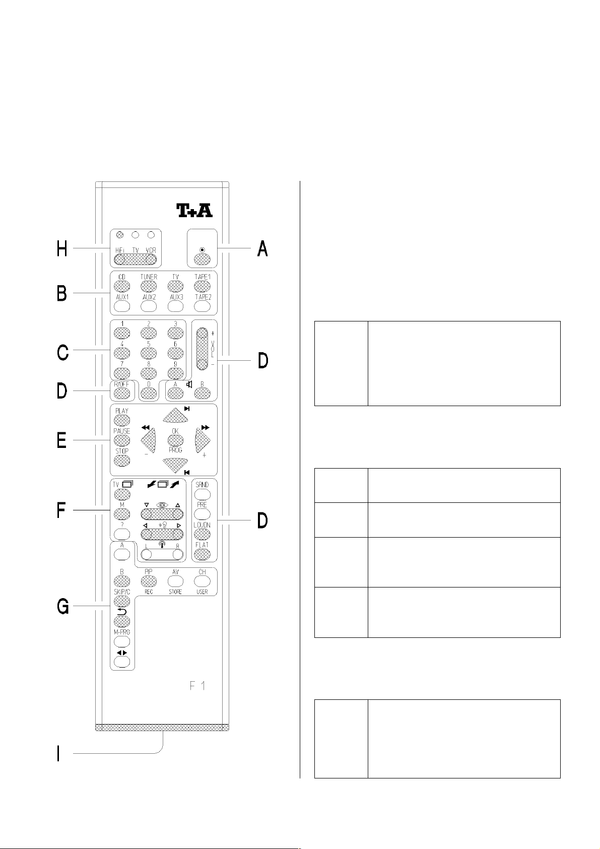
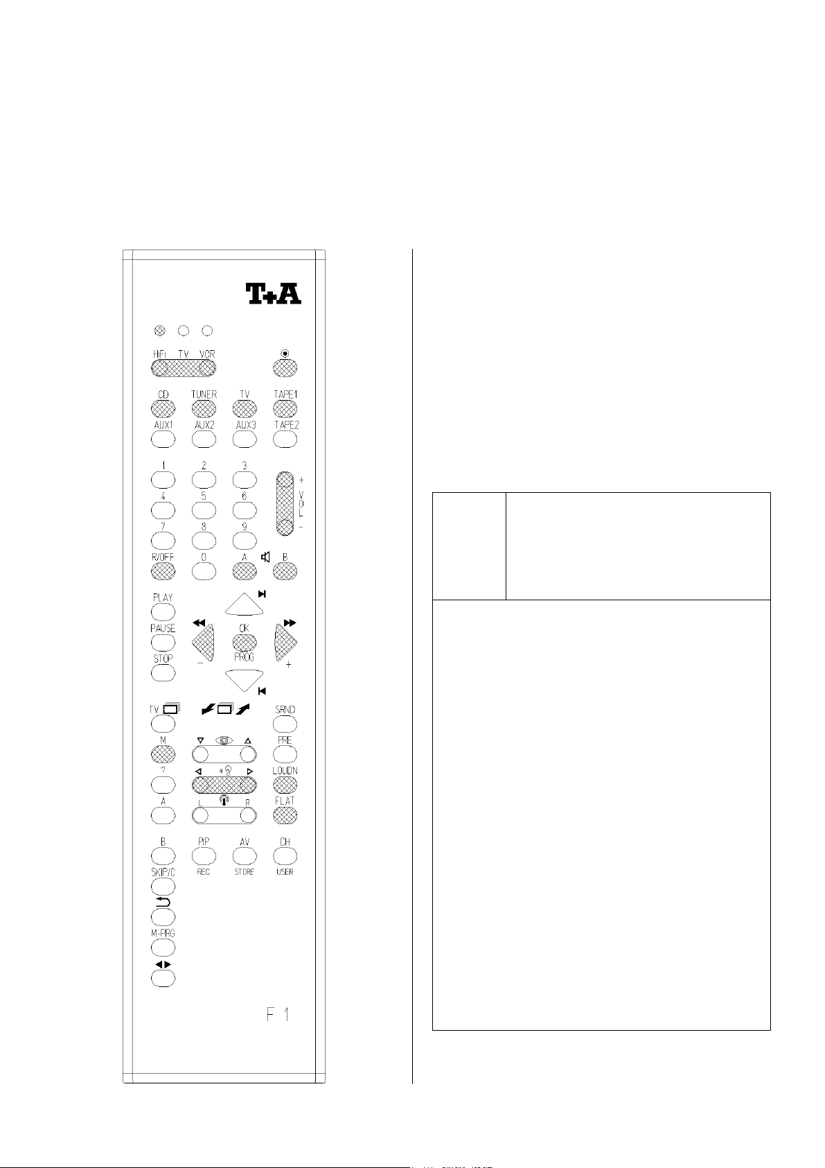
REMOTE CONTROL HANDSET F1
Your K5 is supplied complete with an F1
remote control handset. In the diagram the
remote unit is divided up into areas and the
relevant buttons are shaded in like this:
’
Area A (ON / OFF):
n
n
nn
’.
Switches the unit ON from standby, or to stand-by from ON. The
K5 must be switched on at the
main ON/OFF switch for this to
work.
Area B (source select):
Selects the integral CD player as
#
#
##
listening source.
Selects the integral tuner as listen-
N
N
NN
ing source.
Selects the device which is con-
Z
Z
ZZ
nected to the external socket
AUX/TV as listening source.
Selects a cassette recorder con-
g
g
gg
nected to the external TAPE input
as listening source.
Area C (numeric keypad):
The numeric buttons are used for
É
É
ÉÉ
Ê
Ê
ÊÊ
:
direct entry of pre-sets in tuner
mode, and for direct track select in
CD mode.
6
Page 7
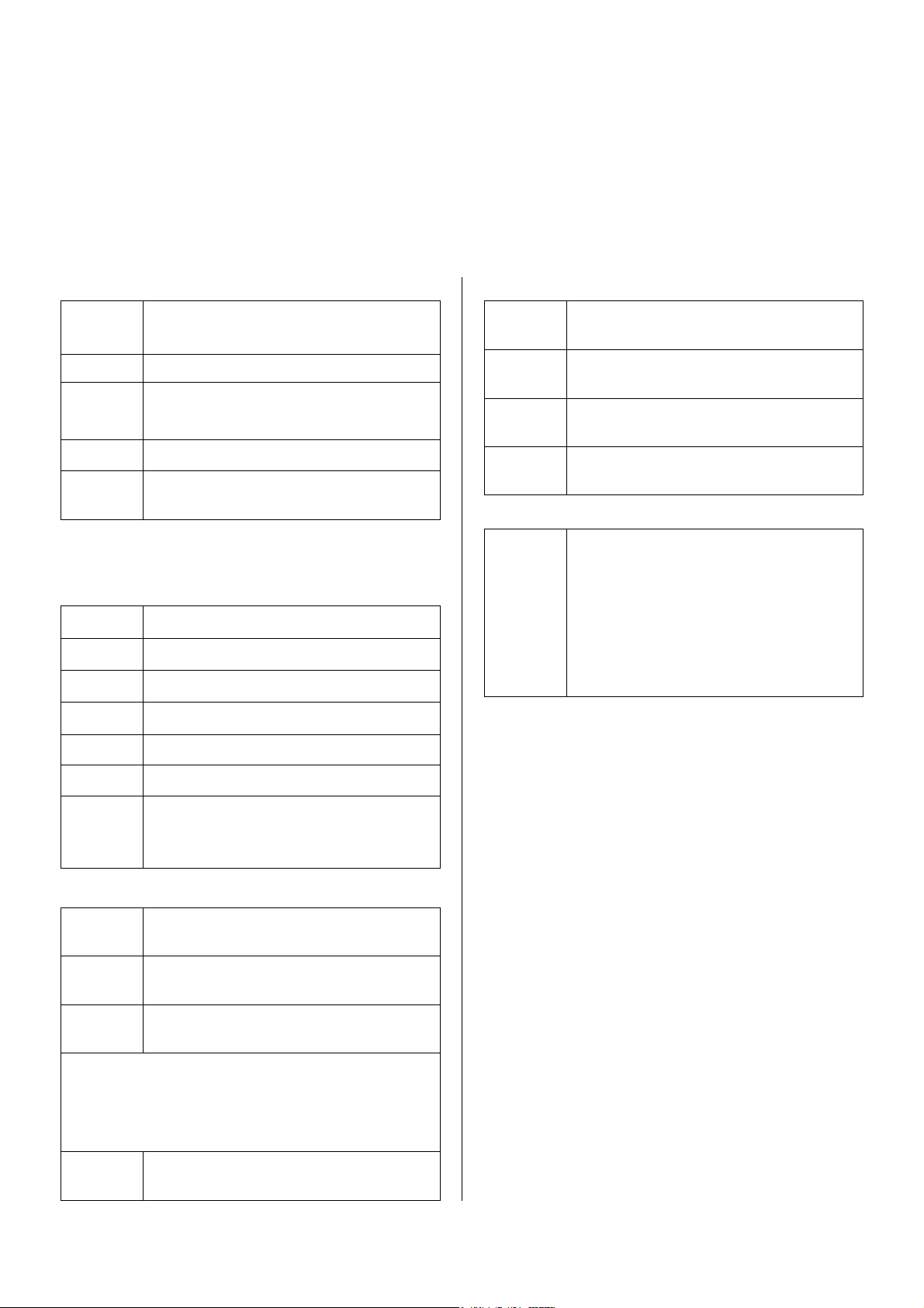
Area D (pre-amplifier functions):
Raises / lowers the volume in
;
;
;;
Ï
Ï
ÏÏ
j
j
jj
k
k
kk
O
O
OO
&
&
&&
1.25 dB increments.
Switches all loudspeaker outputs off.
Switches the loudspeaker output
Switches loudness On / Off.
Switches low bass enhancement
A /
B On / Off.
On / Off.
Area E (mechanism and pre-set control):
These buttons are used to control the CD
player and tuner.
Ë
Ë
ËË
Skip track or pre-set, backwards.
Area G (special functions):
Switches the DOLBY B noise re-
`
`
``
duction on / off.
Switches MEMORY STOP on/off;
Ð
Ð
ÐÐ
l
l
ll
Set the tape counter to '0.00'.
Selects the different playback modes when playing a CD/cass..
Switches the cassette recorder to
x
x
xx
„record ready“ mode.
Area H (mode select):
Rocker switch sets the remote
[
[
[[
control to the Hi-Fi, TV or VCR
mode. An LED glows to indicate
the selected mode for 10 second.
The Hi-Fi mode must be selected if
Ì
Ì
ÌÌ
Í
Í
ÍÍ
Skip track or pre-set, forwards.
Back, or increase frequency.
you wish to control the K5. The
green LED lights up in this mode.
Î
Î
ÎÎ
6
6
66
7
7
77
0
0
00
Forward, or reduce frequency.
Starts CD/cass. playback.
Switches CD/cass. to pause mode.
Halts CD/cass. playback.
Opening/closing the CD/cassetten–
drawer.
Area F (menu control and radio text):
Opens the source menu for special
device functions.
Opens the amplifiers special func-
tions menu.
Interrupts the active special functi-
]
]
]]
ons menu.
To move around within the menus
Note:
you need to use the buttons
ÌÌÌÌ
Í
,
Í
ÍÍ
,
Î
Î
ÎÎ
and
\
\
\\
in the
mechanism control area.
Switches radio text display for the
m
m
mm
current station On / Off.
ËËËË
Area I (battery compartment):
To open the battery compartment press in the
latch on the underside of the remote control
handset, then pull the battery holder down
and out. Place the new Micro (LR03) batteries in the holder following the engraved
markings. Push the battery holder into the
handset from the underside until the latch
engages.
Changing the remote control level:
[
Hold the
[
[[
rocker pressed in for a few
seconds until all three LEDs light up. Now
Ê
push one of the numeric keys
The numeric key
,
control system to the normal level; the numeric key
.
Ê
Ê
ÊÊ
sets the remote
sets the alternative level.
Ê
ÊÊ
or
When you have selected the level, the LEDs
go out to confirm your choice.
7
Page 8
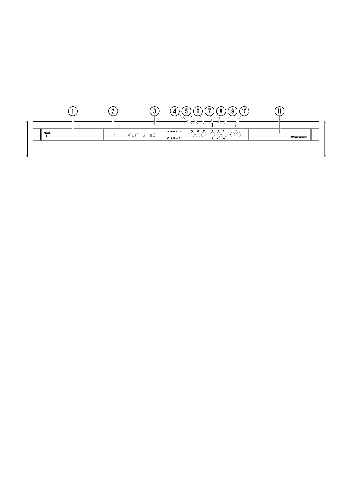
THE FRONT PANEL CONTROLS
We have developed an overall methodology
for controlling the system based on a small
number of buttons, each of which has several
functions depending on the situation. To help
you understand the system the buttons are
duplicated by illuminated symbols which
indicate their current function.
CD DRAWER
r
Press the
r
rr
button to open and close
the CD drawer.
HEADPHONES
Barrel socket (ø3.5 mm) for headphones,
minimum impedance 50 Ω.
INFORMATION SCREEN
All the system's information displays are
shown on a clearly legible screen, carefully
laid out to make it easy to understand. At any
one time the screen only shows the essential
information relating to the current auditioning source (TUNER or CD). This helps considerably in avoiding confusion. The screen
also shows supplementary information when
required, i.e. seldom needed, machinespecific data. This information is shown in an
alpha-numeric area, in plain language with
the help of symbols. For further information
please read the appropriate chapters.
n
n
nn
The system's On/Off button. When you
ON
switch the system on the screen shows the
auditioning source you have selected, or a
machine-specific message. When you switch
on, the system is always in the setting in
which it was last listened to. The volume is
initially limited to "room level".
Caution: The mains button is not a mains
isolation switch. Even when the Ready indicator on the screen is not glowing, a few
parts of the machine are still connected to the
mains power supply. If the unit is not to be
used for a long period it should be isolated
from the mains by pulling out the mains plug
at the wall socket.
o
o
oo
The term source device means the compo-
SOURCE SELECT
nents of a Hi-Fi system which supply a sound
signal, such as tuner, CD player, cassette
deck etc. Pressing the
o
oo
button shows
o
the system's currently active source device on
the screen. Pressing this button repeatedly
cycles through the available source devices
1)
TUNER
1)
1)
Internal
- CD 1) - AUX/TV 2) - TAPE
2)
External
8
Page 9

Ä
Ä
ÄÄ
This button switches the integral cassette re-
RECORD
corder to the „record ready“ state, if a recordable tape (record/erase lug not removed) is
• Starts playback; selects the next track du-
ring CD-playback.
• Reverses the direction of play during cas-
sette playback.
in the cassette drawer.
q
q
qq
r
r
rr
Combination button for ending CD/cassette
STOP
OPEN
playback and for opening and closing the
current drawer.
Note:
The
r
button opens the CD drawer
only if the integral CD player is selected as
the current listening source; otherwise it opens the cassette drawer.
s
s
ss
t
t
tt
PAUSE
TIMER ON
Pauses CD/cassette playback, i.e. the track
• Selects the next preset in tuner mode.
Holding the button pressed in for longer
than about a second has this effect:
• Jumping to the start of the preceding track.
You can jump back several tracks in this
way.
• Selects the preceding preset in tuner mode.
w
w
ww
The machine features a digital volume con-
VOLUME
trol system. Every time you press the lefthand VOLUME button the volume level is
reduced. Every time you press the right-hand
VOLUME button the volume level is increased.
currently playing is interrupted. Playback
The current volume level is shown briefly on
resumes when you press the button a second
time.
the screen. If you hold one of the VOLUME
buttons pressed in for longer than a second,
The same button is used to switch the Timer
on and off when the tuner has been selected
the volume alters continuously until you release the button again.
as the auditioning source.
In Timer mode these buttons are used to ad-
u
u
uu
v
v
vv
Combination button for starting CD/cassette
PLAY
BACK / FORWARD
playback, for jumping to a particular track
and for changing presets when using the
tuner.
Pressing the button briefly has this effect:
just the alarm time.
>>>>
CASSETTE DRAWER
If the cassette recorder, tuner or AUX/TV is
selected as the current source device, pressing the
r
button opens and closes the
cassette recorder drawer.
• A brief press starts the CD/cassette
drawer from STOP mode (PLAY function).
9
Page 10

OPERATING THE AMPLIFIER
VOLUME CONTROL
The machine features a digital volume con-
w
trol system. Every time you press a
w
ww
button, the volume is …
… increased (right-hand button)
… reduced (left-hand button)
The current volume level is shown briefly on
or
...by 1.25 dB.
the screen as a numeric value (0 … 63), e.g.:
'VOLUME 32'
The enormously wide range of volume levels
(0 … 78.75 dB) available, combined with the
perfect channel matching, provide ultra-fine,
highly accurate volume control.
SELECTING THE SOURCE DEVICE
The term source device means any
component of a Hi-Fi system which supplies
a sound signal, such as tuner, CD player,
cassette deck etc.
The term auditioning device means the machine which you are actually listening to.
In addition to the integral listening sources tuner, CD player or cassette recorder - the K5
can be switched to the pre-amplifier input
AUX/TV, to which an external listening
source can be connected, such as the sound
output of a television set.
Press the
o
oo
button briefly to change
o
the auditioning device.
• The current auditioning source (e.g.
Tuner) is now shown on the screen:
'TUNER'.
• Pressing the
o
oo
button repeatedly
o
cycles through all the auditioning sources
on the screen.
• Release the button to select the source you
wish to listen to, and after one second the
screen shows the standard machinespecific display for the chosen source unit.
• The system then reproduces the signal
from that source.
As a basic rule, the integral cassette recorder
can only make a tape recording of the source
device which is current selected as the listening source.
10
Page 11
OPERATING THE AMPLIFIER BY REMOTE CONTROL
GENERAL INFORMATION
In the drawing of the remote control handset
shown alongside the buttons marked
"
trol the amplifier. None of the other buttons
have any effect on the amplifier. To be able
to remote-control the unit the F1 remote
control handset must be set to HiFi operation
by pressing the left-hand end of the
rocker repeatedly until the LED lights up
over 'HiFi'.
" are those which are used to con-
[
[
[[
ON
n
n
nn
If the system is already switched on,
n
the
n
nn
button on the remote
control handset switches the system
to stand-by mode.
In stand-by mode the screen just shows the
time of day. The time display indicates that
the machine is able to respond to remote
control signals. However, the power consumption of the system is reduced to less
than 1 Watt in this mode. Pressing the
n
n
nn
button on the handset a second time
switches the system on again.
Note:
If the system is set to single-room mode
¾
(see SETUP functions), the machine reverts to the settings which were in use last
time you listened to the system.
If the system is set to multi-room mode,
¾
only the loudspeakers in the room where
the user is located are switched on, i.e.
Speaker
Speaker
A in the main room, or
B in the secondary room. The
volume is limited to "room level" when
you initially switch on.
11
Page 12

VOLUME CONTROL
Every time you press the
;
;
;;
rocker the volume level is
If you hold the
… reduced
… increased
pressed in for more than one second, the volume alters continuously until you release the rocker
again.
Every time you alter the volume,
the screen briefly displays the current value.
or
;
;
;;
by 1.25 dB.
=
=
==
=
=
==
rocker
LOUDNESS / LOW BASS EQUALISATION
This button switches the Loudness
O
O
OO
circuit on and off.
This button switches thr Low Bass
&
&
&&
Equalisation on and off.
SELECTING THE AUDITIONING SOURCE
You select the machine you want to listen to
by pressing one of the source buttons. The
signal from this source is then reproduced by
SPEAKER OUTPUTS
j
j
jj
k
k
kk
This button switches the speaker
output
A and/or
If you press one of the buttons, the
new status is shown briefly on the
alpha-numeric screen, e.g.:
'SP A ON' or 'SP A OFF'
The current status of the loudspeaker outputs is also displayed conti-
B on or off.
the system.
At any one time you can only remote-control
the machine which is currently selected as
the auditioning source. The auditioning sources are selected using the following buttons
on the remote control handset:
internal CD player
#
#
##
nuously on the screen in the form
internal tuner
source device connected to the preamplifier input AUX/TV
internal cassette recorder
Ï
Ï
ÏÏ
of a letter 'A' or 'B'.
Switches all loudspeaker outputs
off., for a short time the message
'SP AB OFF’ is displayed.
N
N
NN
Z
Z
ZZ
g
g
gg
Note:
When you switch the system on, the speaker
outputs are initially switched off. After a
short delay period the active speaker output
switches itself on.
Note:
When you switch sources the screen shows
the newly selected auditioning source briefly.
It then reverts to a standard machine-specific
display.
12
Page 13

AMPLIFIER SPECIAL FUNCTIONS
MENU CONTROL SYSTEM
The special functions menu contains those
amplifier functions which cannot be accessed
directly by their own buttons on the front
panel. Instead they are accessed and controlled by a menu control system operated from
the remote-control handset.
Balance setting (BALANCE)
•
Bass tone control (BASS)
•
Treble tone control (TREBLE)
•
•
Set-up functions (SETUP)
Changing display brightness
-
(DIMMER)
Setting the time of day (CLK)
-
Single-room / multi-room mode
-
Separate volumecontrol
(VOL A/B)
Changing AUX input sensitivity
-
(AUX)
The menu system is controlled using the re-
Ó
mote control
Í
Í
Î
Î
,
ÍÍ
, and
ÎÎ
Opens the amplifiers special func-
Ó
ÓÓ
\
\
\\
Ô
Ô
,
ÔÔ
.
]
]
,
]]
tions menu:
Menu point 1: 'BALANCE'
Menu point 2: 'BASS'
Menu point 3: 'TREBLE'
Menu point 4: 'SETUP'
You can interrupt the menu system
]
]
]]
at any time by pressing this button.
Cycles through the previous menu
Ó
Ó
ÓÓ
points in sequence.
Cycles through the next menu
Ô
Ô
ÔÔ
points in sequence.
These buttons are used to make
Í
Í
ÍÍ
changes or make a selection within
Î
Î
ÎÎ
the individual menu points.
,
13
\
\
\\
This button activates the function
shown on the screen. If you have
made no change or selection in the
function on the screen, this button
terminates the special functions
menu.
Page 14
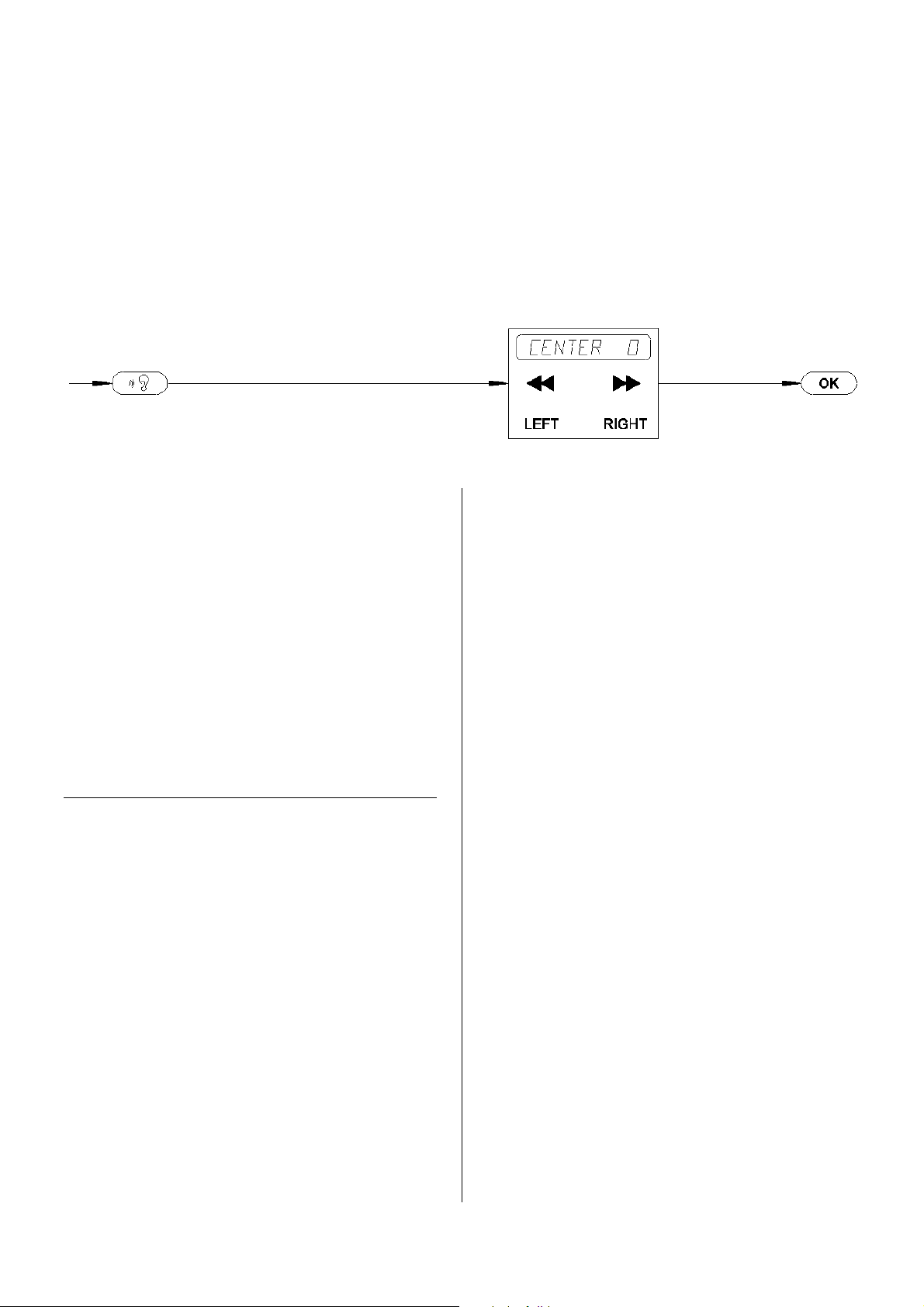
Menu point 1: BALANCE
The balance setting can be adjusted to left or
Introduction:
The 'BALANCE' function is used to adjust
the balance between the left and right channels, e.g. to compensate for non-symmetrical
speaker positioning. The balance setting is
infinitely variable.
Operation:
To change the balance setting press the remote control buttons in the sequence shown
above. The screen then shows the preamplifier's current balance setting, e.g.:
'CENTER 0' = Stereo centre neutral
Í
right in steps. (
Possible adjustment range:
'BAL L 30' (stereo centre fully left)
to
'BAL R 30' (stereo centre fully right)
Any change you make takes effect immedia-
Í
ÍÍ
or
Î
Î
ÎÎ
button)
tely.
If none of the menu control buttons
(
Í
,
ÍÍ
Í
,
Î
Î
ÎÎ
or
\
\
\\
) are pressed
for a period of about ten seconds, the unit
interrupts the special functions menu and
reverts to the standard display. (time-out).
You can interrupt the 'BALANCE' function
]
at any time by pressing the
]
]]
button
again.
Note:
If the stereo centre is set to any value other
than neutral, every time you alter the volume
level the balance setting will appear briefly
on the screen after the current volume value,
e.g. 'VOL 27 L', which means that the stereo
centre is offset to the (L)eft.
14
Page 15
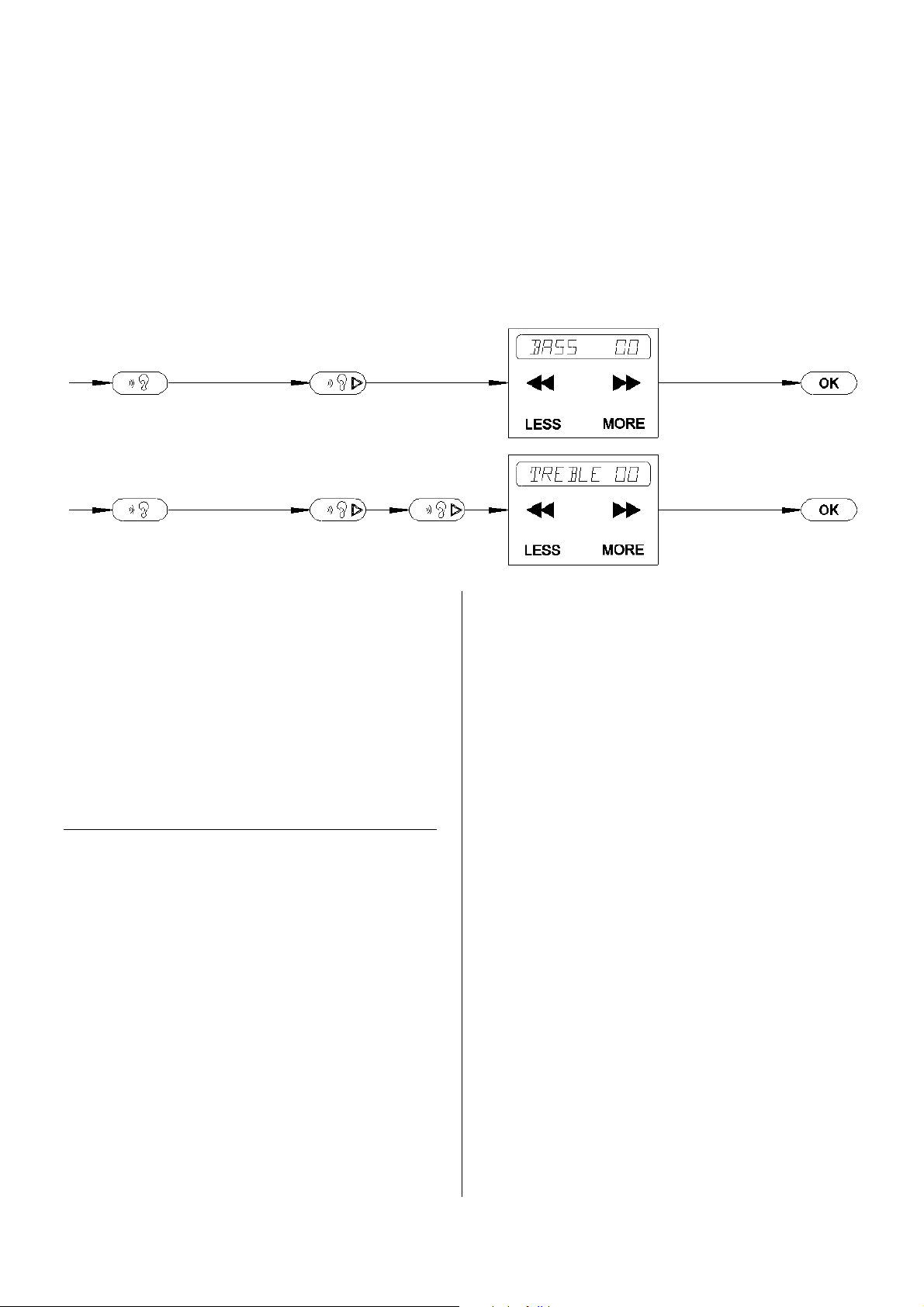
Menu point 2 + 3: BASS + TREBLE
Introduction:
The system features active tone control facilities. The tone controls are designed to compensate for the negative effects of adverse
loudspeaker positions or unusual conditions
in the listening room.
Operation:
To change the tone settings press the remote
control buttons in the sequence shown above.
The screen shows the current bass or treble
setting for both stereo channels, e.g.:
'BASS +02'
or
'TREBLE+04'
These settings can be altered over the range
- 14 dB (less bass / treble)
to
+14 dB (more bass / treble)
Í
Í
(
ÍÍ
or
Î
Î
ÎÎ
–button)
Any change you make takes effect immediately.
If none of the menu control buttons
(
Í
Í
,
ÍÍ
/
Î
Î
ÎÎ
or
\
\
\\
) are pressed
for a period of about ten seconds, the unit
interrupts the special functions menu and
reverts to the standard display. (time-out).
You can interrupt the functions 'BASS' and
'TREBLE' at any time by pressing the
]
]
]]
button.
15
Page 16
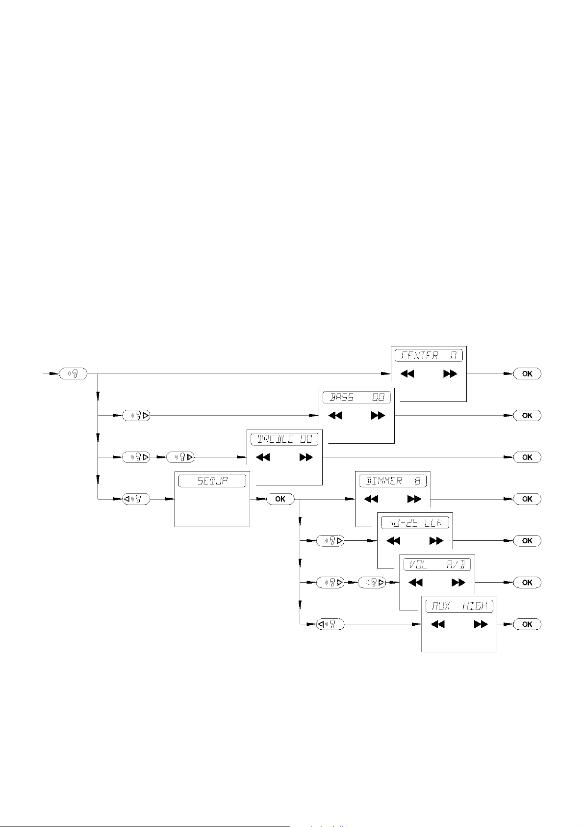
Menu point 4: SETUP
Menu point 4 (SETUP) contains the following set-up functions, which are only rarely
required:
SETUP-function 1: 'DIMMER'
•
SETUP-function 2: '10-25 CLK'
•
SETUP-function 3: 'VOL A/B'
•
• SETUP-function 4: 'AUX'
The diagram below shows the inegration of
the set-up functions into the amplifier special
functions.
16
Page 17
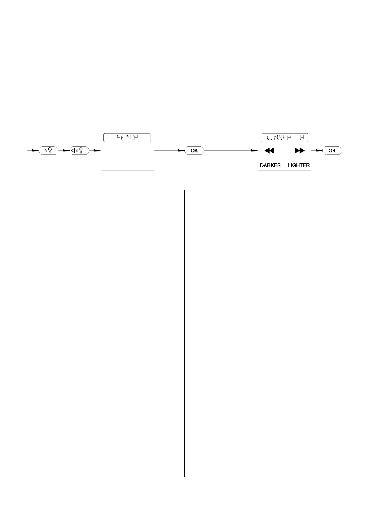
Menu point 4: SETUP - SETUP-function 1: DIMMER
Introduction:
The brightness of the screen on the front panel can be set to any of eight levels (1..8):
This facility allows you to adjust the screen
'DIMMER 1' = darkest level
:
'DIMMER 8' = brightest level
to suit the lighting conditions in your listening room.
Operation:
To alter screen brightness press the remote
control buttons in the sequence shown above.
The screen then shows the current brightness
level (e.g. 3):
'DIMMER 3'
You can change the current setting by pres-
Í
sing the remote control buttons
Any change you make takes effect immedia-
Í
ÍÍ
or
Î
Î
ÎÎ
.
tely.
If none of the menu control buttons
(
Í
Í
,
ÍÍ
/
Î
Î
ÎÎ
or
\
\
\\
) are pressed
for a period of about ten seconds, the unit
interrupts the special functions menu and
reverts to the standard display. (time-out).
You can interrupt the DIMMER set-up
]
function at any time by pressing the
]
]]
button.
17
Page 18

Menu point 4: SETUP - SETUP-function 2: SETTING THE CLOCK
Introduction:
The presence of the integral clock allows you
to set the machine to switch itself on automatically at a pre-programmed time. To use
this facility you must first set the clock to the
correct time.
Operation:
You can change the set time by pressing the
the remote control buttons in the sequence
shown above. The screen shows the time of
day which is currently set, e.g.
'10-25 CLK'.
You can change the set time by pressing the
Í
remote control buttons
Í
ÍÍ
or
Î
Î
ÎÎ
; when
you start doing this, the word 'CLK' starts to
flash.
The time alters at three different speeds, depending on the length of time you hold the
buttons pressed in.
Once you have set the time correctly, press
\
the
\
\\
button to store it. The screen
shows 'SET' instead of 'CLK' for one second, e.g.: '10-25 SET'
If none of the menu control buttons
(
Í
Í
,
ÍÍ
/
Î
Î
ÎÎ
or
\
\
\\
) are pressed
for a period of about ten seconds (or, after
changing the clock setting, for 90 seconds),
the unit interrupts the special functions menu
and reverts to the standard display. (timeout).
You can interrupt the Setup function 'Setting
the Clock' at any time by pressing the
]
]
]]
button. In this case the machine
does not store the altered clock time.
18
Page 19
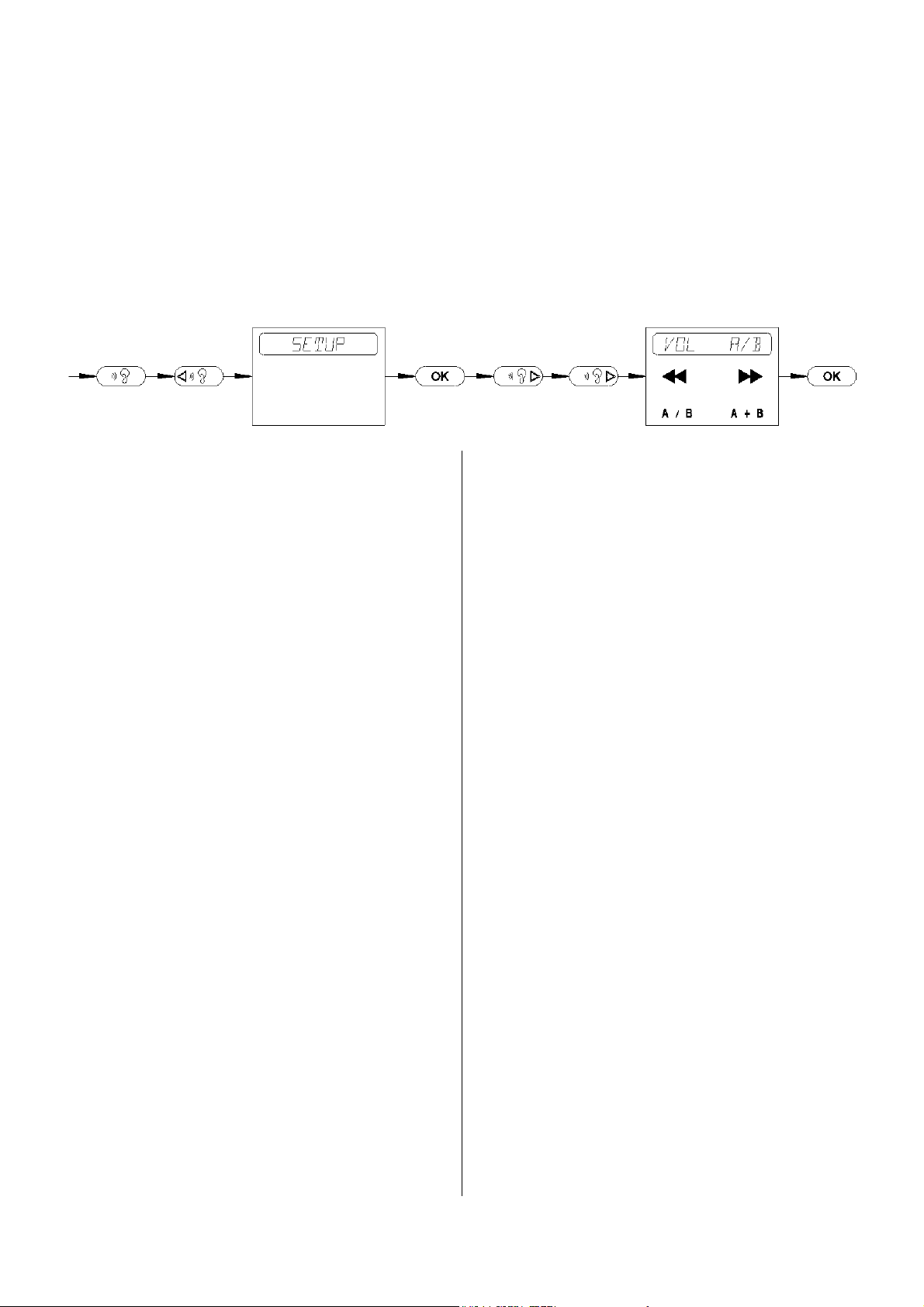
Menu point 4: SETUP - SETUP-function 3: SEPARATE VOLUME ADJUSTMENT
Introduction:
In normal the volume of the speaker output
A and
B are controlled in common.
Operation:
To alter the option press the remote control
buttons in the sequence shown above.
If you connect an additional remote control
receiver and a pair of loudspeakers to the
speaker connections
B (preferably in a
different living room), it is possible to adjust
the volume separately for the pairs of speakers
A und
B.
If the system is set to multi-room mode,
only the loudspeakers in the room where the
user is located are switched on; the other
speakers keep quiet.
The volume for speaker
=
tered using the
=
==
A can only be al-
buttons on the machine's front panel, or via the integral remote
control receiver.
The volume for speaker
B can only be adjusted via an external remote control receiver
(see also "multi-room sound system" in the
chapter CONNECTING THE SYSTEM,
THE SYSTEM IN USE).
The screen shows the current setting, e.g.
VOL A/B
'
separate volume adjustment
'
(multi room sound system)
or
'VOL A+B' common volume adjustment
(single room sound system)
Í
Í
You can select the option with the
Î
Î
button.
ÎÎ
ÍÍ
or
If none of the menu control buttons
(
Í
Í
,
ÍÍ
/
Î
Î
ÎÎ
or
\
\
\\
) are pressed
for a period of about ten seconds, the unit
interrupts the special functions menu and
reverts to the standard display. (time-out).
You can interrupt the SETUP function
SEPARATE VOLUME ADJUSTMENT at
]
any time by pressing the
]
]]
button.
19
Page 20
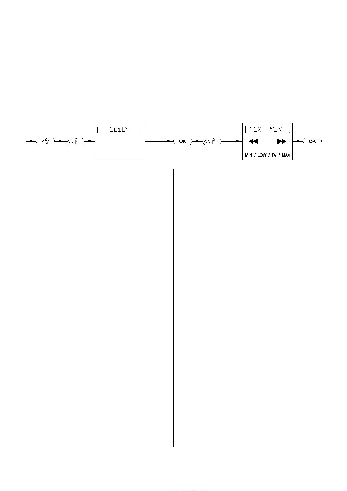
Menu point 4: SETUP - SETUP-function 4: INPUT SENSITIVITY AUX/TV
Introduction:
The sensitivity of the AUX/TV input can be
changed to any of four settings so that you
can continue to use source devices which are
quieter than normal without suffering a
disturbing change in volume when you
switch from one source to another:
The volume corresponds to the setting you
'AUX MIN'
'AUX LOW'
'AUX TV'
'AUX MAX'
choose, i.e. it is quietest at the 'MIN' setting
and loudest at the 'MAX' setting.
Note:
To avoid overloading the input sensitivity
should be set to 'MIN'.when a high level
source is connected to the AUX/TV input.
Operation:
To alter input senstivity of the AUX/TV input press the remote control buttons in the
sequence shown above.
The screen then shows the current brightness
level e.g.:
You can change the current setting by pressing the remote control buttons
Î
Î
. Any change you make takes effect im-
ÎÎ
'AUX MIN'
Í
Í
ÍÍ
oder
mediately.
If none of the menu control buttons
(
Í
Í
,
ÍÍ
/
Î
Î
ÎÎ
oder
\
\
\\
) are pressed for a period of about ten seconds, the unit
interrupts the special functions menu and
reverts to the standard display. (time-out).
You can interrupt the SETUP function
INPUT SENSITIVITY AUX/TV at any time
]
by pressing the
]
]]
button.
20
Page 21

21
Page 22

OPERATING THE TUNER
PRESET SELECTION
When you want to listen to the tuner you
must first select it as the current auditioning
o
source. This is done by pressing the
o
oo
button repeatedly until the word 'TUNER'
appears on the screen.
The system can store a total of 60 station presets. The preset stores the frequency together
with the other tuner settings (MONO /
STEREO, ATTENUATOR etc.) (see
Chapter "Storing and erasing presets").
When you call up a preset the tuner reverts to
the exact setting in which the preset was stored.
Pressing the
v
vv
button briefly calls up
v
the next stored tuner preset (in ascending
order). If you hold the button pressed in for
longer than one second, the tuner jumps back
to the preceding preset.
v
If you continue to hold the
v
vv
button
pressed in, the tuner continuously jumps back
to the previous preset number until you release the button. Empty memory spots are
automatically skipped.
Note:
If you select a preset and the new station is
broadcasting RDS information, the screen
displays the station's name. Otherwise the
screen shows the new preset number and the
reception frequency. After about a second the
preset number is replaced by a tuning indicator.
TUNER DISPLAY ELEMENTS
This symbol lights up if the station you have
STEREO INDICATOR
selected is broadcasting a stereo signal.
The indicator does not light up if the transmission is in mono, or if the tuner has been
set manually to MONO reception mode -
'RCVM MONO' (see Tuner special functi-
ons).
SIGNAL STRENGTH INDICATOR
This symbol helps you to judge the signal
strength and the quality of reception you can
expect from the selected station. If the symbol lights up, hiss-free MONO reception is
available. The stereo signal may have slight
background hiss.
Note:
The tuner is fitted with an automatic High
Blend circuit. When a stereo signal of ina-
dequate field strength is picked up, this circuit reduces the base width of the stereo signal and thereby reduces the background hiss.
22
Page 23

t
TIMER
The system incorporates an integral clock
module which can be set to switch the machine on automatically at a fixed time of day.
For this to work properly you have to set the
internal clock to the correct time of day, and
then set the power-on time. The time of day
is set in the special function 'SETUP' (see the
Chapter "Menu control system").
If you want to switch the timer on and off
you must first select the tuner as the current
auditioning source. This is because the timer
always switches the system on set to the au-
Pressing the
t
tt
the timer. The screen confirms this by showing the message 'ALARM OFF' briefly.
If you now switch the machine to STANDBY mode when the timer has been set to active (by pressing the
front of the unit or on the RC handset), then
it will switch itself on again at the programmed time - see 'ALARM'.
Note:
When in STAND-BY mode the machine can
temporarily show the alarm time if you press
t
the
t
tt
button (no longer glowing).
button again cancels
n
n
nn
button at the
ditioning source TUNER, as this is the only
A longer press (about 1 second) with the ma-
way to ensure that a source signal is always
present when the timer is tripped.
chine in STAND-BY mode cancels the timer,
and the screen confirms your action by
PROGRAMMING THE TIMER
First select the TUNER as auditioning sour-
ce. Select the station and set the volume at
which you want the machine to switch itself
on. Pressing the
t
tt
button now swit-
t
ches the machine to Timer Set mode. If you
have already selected a power-on time, the
time you have set appears on the screen: e.g.
'14-38 TIM', with 'TIM' (TIMer) flashing.
displaying the message: 'ALARM OFF'.
ALARM - with automatic power-off
When the unit switches itself on under timer
control, the illuminated
symbol flashes.
This indicates that the timer will automatically switch the unit back to STAND-BY
mode after about one hour.
You can now move the time setting forward
or back using the VOLUME buttons. If you
hold the buttons pressed in, the rate of change increases.
To activate the timer hold the button pressed
in for about a second. The screen briefly
shows the switch-on time and 'SET' instead
of 'TIM', e.g. '14-38 SET'. At the same
time the screen indicates that the timer is ac-
tive by showing the glowing
symbol.
If you operate any control on the unit during
this one-hour period (e.g. you alter the volume level or change pre-sets), then the illumi-
nated
symbol stops flashing. The timer
will now no longer switch off automatically
after an hour. If you wish to switch it off, you
must do so manually!
23
Page 24

OPERATING THE TUNER BY REMOTE CONTROL
GENERAL INFORMATION
The tuning button on the machine's front panel provides only limited control of the tuner.
The remote control handset provides full
control in the most convenient manner.
The tuner must be selected as the auditioning
source. The handset only controls currently
auditioning source.
In the drawing alongside the buttons marked
"
" are those which are used to operate the tuner. None of the other buttons have
any effect on the tuner.
SELECTING THE TUNER AS
AUDITIONING SOURCE
Selects the system's integral tuner
N
N
NN
as the current auditioning source.
The screen briefly displays the
word 'TUNER', then reverts to the
standard tuner screen. From now
on all remote control commands
are passed to the tuner.
24
Page 25

SELECTING A PRESET AND STATION
Calls up the preset with the next
Ë
Ë
ËË
lower preset number; empty memory spots are automatically skipped.
Calls up the preset with the next
Ì
Ì
ÌÌ
higher preset number; empty memory spots are automatically skipped.
Pressing this button briefly drops
Í
Í
ÍÍ
the reception frequency of the tuner by a 25 kHz step.
NUMERIC PRESET SELECTION
NUMERIC BUTTONS
Ê
Ê
ÊÊ
:
É
É
ÉÉ
Numeric input for direct selection
of a preset.
When you press one of the numeric
buttons the screen shows the letter
'P' for PRESET together with the
number you just pressed. The system now waits for about 2 seconds;
if within that time you press a second numeric button, then it is assumed to be the second digit of the
Pressing this button briefly raises
Î
Î
ÎÎ
the reception frequency of the tuner by a 25 kHz step.
Í
If one of the tuning buttons (
Í
ÍÍ
oder
Î
Î
ÎÎ
is held pressed in for about a second, the tuner starts a station search in the corresponding direction (down or up). It stops automatically at the next station broadcasting an adequate signal, and then tunes it in accurately.
)
preset number.
If you do not press a second button, the machine assumes that you
have selected a preset with a single-digit number. The preset is activated when you enter the second
number, or when the two-second
waiting period has elapsed.
The machine ignores invalid preset
numbers (lower than 01 or higher
than 60); the display shows:
If you now release the tuning button, the machine stays tuned to that station. If you continue to hold the button pressed in, then the
machine resumes the search after about a second. You can interrupt the search process at
any time by pressing the opposite tuning
button. At this point a short press of any preset button (
ËËËË
oder
ÌÌÌÌ
) activates the last
preset you used.
'Pxx ERROR'.
Empty Presets are also ignored and
displayed as:
'Pxx - - - - -'.
25
Page 26

SWITCHING RADIOTEXT ON / OFF
Pressing this button briefly swit-
m
m
mm
ches the radiotext display on and
off for the station currently selected.
When first switched on the machine’s screen displays
'RADIOTEXT' until a new message is displayed.
If no radiotext is received for the
selected station, the screen shows
the message 'NO RTEXT' for about one second, and then resumes
the normal display.
When the radiotext function is
switched off, the screen shows the
message 'NO RTEXT'.
DISPLAYING PRESET NUMBERS AND
RECEPTION FREQUENCY
Pressing this button briefly repla-
\
\
\\
ces the RDS station name on the
screen with the current preset
number, together with the associated station frequency. This information stays on the screen for about two seconds.
If you switch to a new station the
radiotext display is automatically
halted; if you wish to see it again
you must switch it on by pressing
m
the
m
mm
button once more.
26
Page 27

TUNER SPECIAL FUNCTIONS
MENU CONTROL SYSTEM
The special functions menu contains the tuner functions which cannot be accessed by
their own buttons on the front panel. Instead
they are controlled via a remote-control menu
system:
Changing the reception mode
•
(ReCeiVeMode) (RCVM)
• Storing and erasing presets (PRESET)
The menu system is operated using the re-
Ò
mote control buttons
]
]
]]
Í
Í
Î
,
Î
,
ÎÎ
and
ÍÍ
This button opens a menu offering
Ò
ÒÒ
\
\
\\
,
.
Ñ
Ñ
ÑÑ
two tuner special functions:
Menu point 1.'RCVM'
Menu point 2.'PRESET'
You can interrupt the menu system
]
]
]]
at any time by pressing this button.
Shows the previous menu point in
Ñ
Ñ
ÑÑ
sequence.
Shows the next menu point in se-
Ò
Ò
ÒÒ
quence.
These buttons are used to make a
Í
Í
ÍÍ
selection or perform any changes
Î
Î
ÎÎ
Ë
Ë
ËË
Ì
Ì
ÌÌ
\
\
\\
within the menu points.
Activates the function shown on
the screen. If you have made no
change or selection in the function
\
on the screen, pressing
\
\\
terminates the tuner special functions menu.
,
27
Page 28

Menu point 1: RCVM
Introduction:
The tuner can be set to any of three different
reception modes (ReCeiVeMode = RCVM).
Reception mode
normal STEREO
normal STEREO mit
with aerial attenuator
MONO
The standard tuner setting is STEREO
Screen display:
RCVM NORM
RCVM ATT
RCVM MONO
(RCVM NORM). In this mode the tuner
suppresses interference from adjacent
stations, providing outstandingly good
reproduction quality even under difficult
reception conditions.
Selecting the reception mode 'RCVM
MONO' automatically reduces the search
threshold. The automatic station search function now also stops at distant, weak and
slightly "hissy" stations.
Operation:
To change the reception mode press the remote control buttons in the sequence shown
above. Pressing the remote control buttons
Í
Í
ÍÍ
and
Î
Î
changes the current reception
ÎÎ
mode, and the new mode then appears on the
screen. Any change you make takes effect
If you try to receive stations close to an unusually powerful local station you may encounter intermodulation effects (whistling
and twittering "birdie" noises).
In this type of case we recommend that you
switch on the aerial attenuator; the message
'RCVM ATT' then appears on the screen.
immediately.
The function is terminated by pressing the
\
\
\\
If none of the menu control buttons
(
button.
Í
Í
,
ÍÍ
,
Î
Î
ÎÎ
or
\
\
\\
) are pressed
for a period of about ten seconds, the unit
Very weak or very distant stations can usually only be picked up with serious background hiss, and in this case you should
switch to MONO reception, as this reduces
the hiss significantly.
interrupts the special functions menu and
reverts to the standard display. (time-out).
You can interrupt the function 'RCVM' at
]
any time by pressing the
]
]]
button.
28
Page 29

Menu point 2: PRESET - PRESET-FUNCTION 1: STORING PRESETS MANUALLY
Introduction:
The tuner can store a total of 60 station settings (presets). The preset stores the frequency and the reception mode, and also the
RDS station name - provided that it was
picked up in full at the time it was stored.
When you call up a preset the tuner reverts to
the exact setting in which the preset was
stored.
Operation:
Before you store a preset the station must
first be tuned in accurately; you may have to
wait until the complete RDS station name
appears on the screen. Then you should press
the remote control buttons in the sequence
shown above.
The screen shows a 'P' on the left followed
by a flashing number, with the station frequency after that, e.g.:
'P28 104,90' MHz
The flashing number is the preset number
under which the current station will be
stored. You can change the preset number
using the
ËËËË
and
ÌÌÌÌ
buttons, or you can
enter the number you want to use directly
using the numeric buttons.
To store the setting under the current pre-set
number you must press the
\
\\
button.
\
The screen then shows the message
'STORE' for a brief period instead of the
frequency. The pre-set is now stored, and the
MANUAL STORE process is ended.
If none of the menu control buttons
(
Í
Í
,
ÍÍ
/
Î
Î
ÎÎ
or
\
\
\\
) or the numeric buttons are pressed for a period of about ten seconds, the unit interrupts the special functions menu and reverts to the standard display. (time-out).
You can interrupt the PRESET function
STORING MANUALLY at any time by
]
pressing the
Note:
If you attempt to store an invalid preset num-
]
]]
button.
ber (xx), the machine responds with an error
message on the screen: 'Pxx ERROR'; the
tuner then terminates the special functions
menu.
The RDS norms state that the station name
must be broadcast in static form, but many
stations present the information as a moving
script. If this occurs, do not store the preset
until the transmitter broadcasts its station
name constantly for a fairly stable period.
29
Page 30

Menu point 2: PRESET - PRESET-FUNCTION 2: AUTOMATIC PRESET STORING (AUTOSTORE)
Introduction:
If you select automatic preset storing, the
tuner automatically searches the whole VHF
band twice (using different search thresholds) for stations which can be received well
in STEREO mode, and automatically stores
the stations it finds.
This process can take some time, as the tuner
attempts to receive the complete RDS station
name for each station it finds, so that the
name can be stored in the preset.
If the AUTOSTORE function does not pick
up the RDS station name, but at a later date
the tuner is able to receive it when you are
tuned to that preset, then the station name
appears on the screen and is automatically
stored with the preset.
Operation:
To use the AUTOSTORE function press the
remote control buttons in the sequence
shown above.
As with the manual preset storing procedure
you can use the
ËËËË
and
ÌÌÌÌ
buttons or the
numeric buttons to select a preset number as
the starting point, i.e. the stations the system
locates will be stored after that number.
If you want to store the station information
starting at the beginning, then you should
select the number 01.
If none of the menu control buttons
(
Í
Í
,
ÍÍ
/
Î
Î
ÎÎ
or
\
\
\\
) or the numeric buttons are pressed for a period of about ten seconds, the unit interrupts the special functions menu and reverts to the standard display. (time-out).
Up to this point you can interrupt the
AUTOSTORE function by pressing the
]
]
]]
Pressing the
button.
\
\
\\
button now activates
the AUTOSTORE function, and the frequency display starts to rise incrementally.
30
Page 31

You can interrupt the PRESET function
Í
AUTOSTORE by pressing the
Í
ÍÍ
or
Î
Î
ÎÎ
button.
When the tuner has searched the whole VHF
band, or when the final memory spot is full,
the tuner ends the AUTOSTORE function
and terminates the special functions menu.
Note:
The tuner is not capable of assessing the
quality of each individual station, so it provides the user with a means of editing the
presets manually.
The same facility is useful if you find that
stations have been stored whose RDS station
name was not recognised in full by the
AUTOSTORE function, or that a station
failed to broadcast its RDS name in accordance with the RDS norms.
To edit the presets you call up each one in
turn and attempt to optimise reception quality
by changing the reception mode
(NORM / ATTENUATOR / MONO)
finally you store the preset again manually
(see Manual storing of presets).
Presets which contain stations of such low
quality that they are not worth listening to, or
which contain a duplicate station on a different frequency, should simply be erased (see
Erasing A Preset).
If you repeat the AUTOSTORE process, the
machine will not store the same stations
twice, i.e. frequencies already stored will not
be stored again.
31
Page 32

Menu point 2: PRESET - PRESET-FUNCTION 3: ERASING A PRESET
Introduction:
Presets which contain stations of such low
quality that they are not worth listening to, or
which contain a duplicate station on a different frequency, should simply be erased.
Under certain circumstances, e.g. after a house-move, you may find it necessary to erase
all the pre-sets. In this case please read the
section entitled 'Tuner section' in the 'Trou-
ble Shooting' Chapter.
Operating:
To erase a preset, press the remote control
buttons in the order listed above. The screen
shows a ‘P’ on the left, followed by a flashing number, and the function name
‘CLEAR’. e.g.:
'P28 CLEAR'
The flashing number is the number of the
preset to be erased. You can change it by
pressing the
ËËËË
and
ÌÌÌÌ
buttons, or by entering the number directly using the numeric
buttons.
If none of the menu control buttons
(
Í
Í
,
ÍÍ
/
Î
Î
ÎÎ
or
\
\
\\
) or the numeric buttons are pressed for a period of about ten seconds, the unit interrupts the special functions menu and reverts to the standard display. (time-out).
Up to this point you can interrupt the
]
CLEAR function by pressing the
]
]]
button.
Pressing the
\
\\
button erases the preset
\
and terminates the special functions menu.
Note:
If you attempt to store an invalid preset number (xx), the machine responds with an error
message on the screen: 'Pxx ERROR'; the
tuner then terminates the special functions
menu.
32
Page 33

OPERATING THE CD PLAYER
You can interrupt playback temporarily at
To play a CD:
To listen to the CD player, you must first select it as the current listening source. To do
this press the
o
oo
button repeatedly until
o
‘CD’ appears on the screen.
Open the CD drawer
•
q
q
(
qq
Place a CD in the drawer, printed face up.
•
r
r
/
rr
–button).
• Close the CD drawer
q
q
(
qq
Note:
Immediately the drawer is closed the ma-
r
r
/
rr
–button).
s
any time by pressing the
s
ss
button.
During the interruption the screen shows
'PAUSE'.
Press the
s
ss
button a second time to
s
resume playback.
If you press the
v
vv
button during play-
v
back, the player jumps to the start of the next
track.
v
A long press (about 1 second) on the
v
vv
button during playback causes the player to
jump to the start of the previous track.
If the button is held pressed in, the machine
jumps back repeatedly until you release the
button.
chine reads the disc's "Table of Contents"; at
The screen displays the word 'JUMP' while
this point the screen shows 'READING'.
During this period the machine ignores all
button presses. The screen then shows the
current operating status and the total number
of tracks on the CD in the machine, e.g.:
'STOP 16'.
u
• Start the play process (
Playback begins, and the screen shows the
u
uu
–button).
operating status and the number of the track
currently playing: i.e. : 'PLAY 01'. The CD
stops at the end of the last track and the
screen again shows 'STOP' and the total
number of tracks on the CD.
Variations:
If you press the
button after inserting the CD, the drawer closes and the playback process starts automatically with the
first track.
it is jumping to the next or preceding track.
Pressing the
q
qq
r
r
/
rr
button ends
q
the playback process, and the screen shows:
'STOP'. Pressing the
q
qq
r
r
/
rr
but-
q
ton again when the machine is in STOP
mode opens the CD drawer.
Selecting a track during playback:
v
Press the
v
vv
button repeatedly, or hold
it pressed in, until the number of the track
you want to listen to appears on the screen
after 'PLAY'.
When you release the button the machine
briefly interrupts playback, the screen shows
'JUMP', and then the selected track is
played.
Note:
You can also directly enter the number of the
track you want to hear using the numeric
buttons on the remote control handset.
33
Page 34

OPERATING THE CD-PLAYER BY REMOTE CONTROL
GENERAL INFORMATION
You can operate virtually all the CD mechanism's facilities and all the system's special
functions from the remote control handset.
To be able to remote-control the CD player
the F1 remote control handset must be set to
HiFi operation and the CD player must be
selected as the auditioning source.
In the drawing shown here the buttons
marked '
' are those which are needed
to control the CD player. None of the other
buttons have any effect on the CD player.
SELECTING THE CD AS AUDITIONING
SOURCE
Selects the integral CD player as
#
#
##
the current auditioning source. The
letters 'CD' appear on the screen
briefly, then the screen shows the
standard display for the CD player.
All remote control commands are
now passed to the CD player.
CONTROLLING THE CD MECHANISM
Selects the previous track during
Ë
Ë
ËË
playback.
Selects the next track during play-
Ì
Ì
ÌÌ
back.
34
Page 35

NUMERIC TRACK SELECTION
Í
Í
ÍÍ
Î
Î
ÎÎ
Fast search backwards to locate a
particular passage.
Fast search forward to locate a
particular passage.
After about two seconds the search
speed rises. At the low search
speed you can listen to the music,
but at the higher speed the output
is muted. During the search process the current track time is shown
on the left of the screen. When the
NUMERIC BUTTONS
Ê
Ê
ÊÊ
:
É
É
ÉÉ
Direct numeric input for selecting
a track number.
When you press a numeric button (e.g.
Ê
Ê
ÊÊ
) the screen shows: 'SELECT 1_'.
For a period of 3 seconds a marker flashes.
During this time you may:
search reaches the start or end of
• press a second numeric button to complete
a two-digit track number - the machine
plays the selected track immediately.
• or press the
6
66
button; the input is
6
assumed as a single-digit track number the machine plays the selected track immediately.
• If you do not press a second button and the
3-second period is over, the input assumed
as a single-digit track number - the machine plays the selected track.
Note:
You can also enter a track number directly
when the CD drawer is still open. In this case
the drawer closes automatically and playback
starts with the track you have selected.
This button is used to store MEMO
\
\
\\
programs. If the menu control sys-
\
tem is in use,
\
\\
acts as the
0
0
00
7
7
77
6
6
66
l
l
ll
the CD, the CD stops.
Ends playback; the screen shows
the message: 'STOP'. In STOP-
mode this button opens / closes the
CD-drawer..
Interrupts playback, i.e. the current
track is paused. The screen shows
'PAUSE'. A further brief press on
7
the
7
77
or
6
6
66
button re-
sumes playback.
Pressing the
7
77
button in
7
STOP mode starts PAUSE mode
and causes a jump to the first track
of the CD resp. the MEMO program
Starts playback. If the CD is already playing, it restarts from the
beginning.
Selects the playback mode (see
Menu control system).
confirmation button (see Menu
control system).
35
Page 36

MEMO-PROGRAM
Introduction:
Each MEMO program can store up to twenty
CD tracks in any sequence; it is useful, for
example, when you are preparing to make a
cassette recording. You can only produce a
MEMO program for the CD actually in the
drawer. The program is stored in the machine
until you erase it again, or until you open the
CD drawer.
Making a MEMO program:
Place a CD in the machine, and the screen
displays the total number of tracks on the
disc after the message 'STOP'.
• Activate the MEMO programming mode.
\
(hold the
The screen shows: 'PROG' and a flashing
\
\\
button pressed in
for about 1 second)
number, which is a request for you to enter a
The screen message 'PROG' flashes once to
confirm that the track you have marked has
now been accepted as the first track in the
MEMO program. Select all the other tracks
you wish to include in the same way, storing
each by pressing the
\
\\
button again
\
briefly.
Hinweise:
Instead of using the
ËËËË
/
ÌÌÌÌ
buttons the
wanted track may be selected by pressing the
numeric buttons. It can be stored by pressing
\
\
the
\\
Once you have stored the 20th track the
button as described above.
screen shows the message: 'FULL'. Please
note: if you enter a further track, it will
overwrite the 20th track, i.e. the last one you
entered will be erased.
When you have stored all the tracks you wish
to select, it only remains to terminate the
MEMO programming process.
track number.
• Hold the
ËËËË
or
ÌÌÌÌ
button pressed in until
the number of the track you wish to select
appears on the screen after 'PROG'.
• End MEMO programming.
\
(hold the
The screen shows the message: 'STORED'
\
\\
button pressed in
for about 1 second)
and then displays in sequence all the track
• Store the track in the MEMO program.
\
(press the
\
\\
button briefly)
numbers of the MEMO program you have
just produced, in the sequence in which you
stored them.
36
Page 37

Playing back a MEMO program:
The MEMO program can now be played
back:
• Start the playback process
ÌÌÌÌ
6
6
/
(
Playback begins with the first track of the
66
button)
MEMO program. While a MEMO program is
being played back, the screen shows a letter
'P' before the current track number.
Pressing the buttons
ËËËË
or
ÌÌÌÌ
selects the
previous or next track in the usual way, but
only within the MEMO program.
If you press the fast forward /fast back but-
Í
tons (
Í
ÍÍ
/
Î
Î
) to select a track which is
ÎÎ
not included in the MEMO program, then the
machine plays that track in full before reverting to the MEMO program.
Erasing a MEMO program:
q
Pressing the
q
qq
r
r
/
rr
button when
the machine is in STOP mode opens the CD
drawer and erases the MEMO program.
q
q
(
qq
You can also erase a MEMO program with-
r
r
/
rr
button)
out opening the CD drawer:
• Activate MEMO programming.
\
(hold the
The screen shows: 'PROG' and a flashing
\
\\
button pressed in
for about 1 second)
number, requesting you to enter a track number.
• Erase the MEMO program.
\
(hold the
The screen shows the message: 'CLEAR',
\
\\
button pressed in again
for about 1 second)
and the MEMO program is now erased.
37
Page 38

CD PLAYER SPECIAL FUNCTIONS
MENU CONTROL SYSTEM
The special functions menu contains the CD
player functions which cannot be accessed by
their own buttons on the front panel. Instead
The menu control system is operated using
Ñ
the remote control buttons
]
]
]]
Í
Í
,
ÍÍ
Î
Î
,
ÎÎ
und
\
\
\\
Ñ
ÑÑ
,
.
Ò
Ò
ÒÒ
,
they are operated by a remote-controlled
menu system:
PLAY A-B
•
Selecting the screen mode
•
(DIS TRACK / DIS TIME)
(PLAY AB)
]
]
]]
Opens the menu with the three CD
player special functions:
Menu point 1. 'PLAY AB'
Menu point 2. 'DISPLAY'
Menu point 3. 'REPEAT'
You can interrupt the menu at any
time by pressing this button.
• Selecting the playback mode
(REP OFF / REP ALL /
REP TRACK / REP MIX)
Ñ
Ñ
ÑÑ
Shows the previous menu point in
sequence.
Ò
Ò
ÒÒ
Í
Í
ÍÍ
Î
Î
ÎÎ
\
\
\\
Shows the next menu point in sequence.
These buttons are used to make a
change or a selection within the
menu points.
This button activates the function
shown on the screen. If no change
or selection was made in the function on the screen, pressing the
button terminates the special functions menu.
38
Page 39

Menu point 1: PLAY A-B
Introduction:
The PLAY A-B mode places two time markers on the current CD, and the machine then
repeats the passage between the two markers
constantly. You can end the repetition at any
time by pressing the
0
00
button. The
0
machine then switches to STOP mode, and
the screen shows the status message 'STOP'.
Operation:
First locate the starting point of the passage.
ËËËË
/
ÌÌÌÌ
(
or
Í
Í
ÍÍ
/
Î
Î
ÎÎ
Press the remote control buttons in the sequence shown above.
If none of the menu control buttons
(
Í
Í
,
ÍÍ
/
Î
Î
ÎÎ
\
\
or
\\
) are pressed
for a period of about ten seconds after
pressing
\
\\
button the first time, the
\
unit interrupts the special functions menu and
reverts to the standard display. (time-out).
The screen shows a flashing letter 'A' before
the current track number, requesting you to
enter the start marker:
'PLAY AB 08'.
Ï flashes
\
Set the start marker by pressing the
\
\\
button once.
After a short delay a flashing letter 'B' appears on the screen, requesting you to enter
the end marker; press the
\
\\
button
\
again at the end of the passage you want to
hear repeated.
Once you have entered the end marker the
screen shows: 'PLAY AB', and the player
repeats the passage between the two markers
).
constantly.
Variation:
Locate the start of the sequence to be repeated during the normal playback process,
7
then press the
7
77
button. If you now
activate the PLAY A-B point within the special functions menu (
\
\\
button), the CD
\
will start automatically. You can now set the
start and end markers by pressing the
\
\
\\
button again.
Note:
• The fast forward / rewind (
Í
ÍÍ
/
Î
Î
ÎÎ
)
Í
buttons can be used to locate the start and
end points of a track.
Up to this point you can interrupt the special
]
function by pressing the
]
]]
button.
• Activating the PLAY A-B mode ends
REPEAT MIX or REPEAT TRACK
operation, and erases any existing MEMO
program.
39
Page 40

Menu point 2: REPEAT / MIX-MODE / NORM-PLAY
Introduction:
The system's integral CD player can play
CDs in any of three different operating
modes.
REP OFF: Normal playback
REP ALL: The tracks of the CD or of a
MEMO program are repeated endlessly in the or-
der you have selected.
REP TRACK: The current track is re-
peated.
REP MIX: The tracks of the CD or of a
MEMO program are repeated constantly in random
order.
Operation:
This menu point allows you to change the
playback mode. Place the CD in the machine
and then press the remote control buttons in
the sequence shown above.
Press the
Í
ÍÍ
or
Î
Î
buttons repeatedly to
ÎÎ
Í
cycle through the different playback modes
on the screen:
'REP OFF'
'REP ALL'
'REP TRACK'
'REP MIX'
If none of the menu control buttons
(
Í
Í
,
ÍÍ
/
Î
Î
ÎÎ
or
\
\
\\
) are pressed
for a period of about ten seconds, the unit
interrupts the special functions menu and
reverts to the standard display (time-out).
You can interrupt the function by pressing
]
]
the
]]
Pressing the
button.
\
\
\\
button switches the
machines to the playback mode shown on the
screen.
Note:
If you open the CD drawer and close it again,
the machine always reverts to normal playback mode (REP OFF).
40
Page 41

Menu point 3: DISPLAY
Introduction:
Most CDs contain several tracks. However,
the tracks on some CDs can be very long,
especially when they contain classical music.
To help you re-locate a particular passage
within a long track, the system offers the facility to display the elapsed time of the current track in addition to the track number, in
place of the operating status message
'PLAY'.
Operation:
To switch the track play time display on or
off press the remote control buttons in the
sequence shown above. The screen then
shows the message, e.g.:
'DIS TIME'.
Pressing the
Í
ÍÍ
or
Î
Î
button briefly alter-
ÎÎ
Í
nates between the two display variants on the
screen:
'DIS TIME'
oder
'DIS TRACK'.
If none of the menu control buttons
(
Í
Í
,
ÍÍ
/
Î
Î
ÎÎ
or
\
\
\\
) are pressed
for a period of about ten seconds, the unit
interrupts the special functions menu and
reverts to the standard display (time-out).
You can interrupt the DISPLAY function at
any time without making any change by
pressing the
\
Press the
\
\\
]
]]
button briefly.
button to accept the cur-
]
rent display option shown on the screen.
41
Page 42

OPERATING THE
To play a cassette:
When you want to listen to the cassette you
CASSETTE RECORDER
must first select it as the current auditioning
source. This is done by pressing the
o
button repeatedly until the word 'TAPE' appears on the screen.
Open the cassette drawer
•
q
q
(
qq
r
r
/
rr
button)
The display shows 'OPEN'.
Place the cassette in the tray with the A-
•
side up. The exposed tape should face the
inside of the machine.
• Start playing side A
(press
u
uu
button 1x)
u
or
• Start playing side B
u
(press
u
uu
button 2x)
The display shows 'PB A' or 'PB B', the
digital tape counter starts incrementing.
The tape direction indicator
only lights
up if side B is playing.
Note:
These operating instructions describe all
the tape functions, and in every case we
assume that the cassette is placed in the
tray with the A-side up !
• Close the CD drawer
q
q
(
qq
r
r
/
rr
button)
The unit automatically detects the type of
tape in the cassette, and the display shows
'NORMAL', 'CHROME' or 'METAL' for
about two seconds.
The screen then reverts to the current operational state: 'STOP'; the digital tape
counter reads '0,00'.
Variations:
If you press the
u
uu
button immedi-
u
ately after placing the cassette in the tray,
then the tray closes and the playback process begins with the A-side.
u
If you briefly press the
u
uu
button
again during playback, the unit reverses
the direction of the tape and plays the
other side.
The tape deck will play one cassette side,
both cassette sides in sequence or both
sides continuously, depending on the
PLAY mode you have selected.
Pressing the
q
qq
r
r
/
rr
button
q
ends the playback process immediately.
42
Page 43

Recording
• Search the tape position at which you want
the recording to begin.
• If you like, activate DOLBY noise re-
• Now you can start recording.
u
u
(
uu
s
s
or
ss
button)
If you record from a CD, both drives (CD
and cassette) are started simultanousely
(Synchro Start).
duction system.
You can interrupt recording.
`
`
(
``
-remote control button)
• Select the recording source unit (Tuner,
CD or AUX/TV). (
o
oo
button)
o
• If you record a CD, first search the start
of the track to be recorded or create a
MEMO PROGRAM. Then switch the
CD drive to PAUSE mode
s
s
(
ss
button)
•
s
s
(
ss
button)
If you wish to operate the recording source, you can switch to it by pressing the
o
o
oo
button. This enables you to search
for a different track, create a new MEMO
program or insert a different CD when recording from a CD. When you are finished, set the CD mechanism to PAUSE,
and then switch back to record mode by
• Turn the K5 to "record ready" mode
Ä
Ä
(
ÄÄ
pressing the
button)
o
o
oo
button again.
• Continue recording after interrupt.
Now the K5 automatically switches to re-
u
u
(
uu
s
s
or
ss
button)
corder operation.
• End recording / record ready mode.
ÅÅÅÅ
The record symbol
glows and the
screen shows the current level in place of
the digital tape counter.
When recording from a CD the process
stops at the end of the CD, or the end of
q
q
(
qq
r
r
/
rr
button)
the MEMO program (Synchro-Start).
The K5 record levels are set to default
values and stored as a standard value for
each source unit. To alter the level see
'Setting the recording level '.
Setting the recording level
The default level values can be altered as
well in "record ready" mode as during the
recording.
Ä
To do this press the
Ä
ÄÄ
and
buttons simultanousely until the peak display
on VU meter only exeeds the 0dB mark now
and then.
The K5 automatically stores the changed
value as the new default value for the current
recording source.
43
w
w
ww
Page 44

OPERATING THE CASSETTE RECORDER BY REMOTE CONTROL
GENERAL INFORMATIONS
To be able to remote-control the CD player
the F1 remote control handset must be set to
HiFi operation and the cassette recorder must
be selected as the auditioning source.
The handset only controls currently auditioning source. In the drawing shown here
the buttons marked '
which are needed to control the cassette recorder. None of the other buttons have any
effect on the cassette recorder.
' are those
SELECTING THE CD
AS AUDITIONING SOURCE
g
g
gg
TAPE DRIVE CONTROLS
Ë
Ë
ËË
Ì
Ì
ÌÌ
If you press a button repeatedly, the mechanism rewinds or fast-forwards through the
corresponding number of tracks. The current
number is always shown on the screen: the
display '- 5' means: rewind 5 tracks.
Selects the integral Cassette recorder as the current auditioning
source. The letters 'TAPE' appear
on the screen briefly, then the
screen shows the standard display
for the Cassette recorder. All remote control commands are now
passed to the CD player.
The tape drive runs back to the
start of the current track.
The tape drive runs to the start of
the next track.
Note:
This function only operates satisfactorily if
there is a gap (silence) between tracks of at
least 3 seconds.
44
Page 45

Í
Í
ÍÍ
Î
Î
ÎÎ
6
6
66
7
7
77
Rewind and fast forward. If the
tape drive reaches the end of the
tape (or the tape counter position
'0,00' if MEMORY STOP is
switched on), then it stops. The
display shows: 'STOP'.
If either the
Í
ÍÍ
or
Î
Î
ÎÎ
button is
Í
held pressed in for about one
second during fast forward or
rewind, then the tape drive will
stop when it reaches the end of the
tape and starts playback.
If MEMORY STOP is switched
on, and the drive reaches the tape
counter position '0,00' then immediately starts the playback process.
Starts the playback process in the
last active direction (see arrow in-
dicators:
). If the cassette is
already running, this button reverses the direction of play.
If the unit is in "record ready"
mode, this button starts recording
in the last active direction.
Equal to button
u
uu
.
u
Temporarily halts recording or
playback, i.e. interrupts the current
track; the display shows: 'PAUSE',
and the tape direction indicator
flashes.
A further brief press on the
7
7
77
button or the
6
6
66
button resumes recording or playback in the former direction.
s
Equal to button
s
ss
.
0
0
00
º
º
ºº
Ð
Ð
ÐÐ
Halts recording or playback. The
display shows: 'STOP'.
q
Equal to button
q
qq
.
In STOP mode this button opens
the cassette drawer.
r
Equal to button
r
rr
.
Switches the cassette recorder to
"record ready" mode. The record
ÅÅÅÅ
symbol
glows and the screen
shows a VU meter instead of the
tape counter.
Ä
Equal to button
Ä
ÄÄ
.
A long press on this button (about
one second) switches Memory
Stop on and off. A short press resets the digital tape counter to
'0,00'. The MEMORY STOP
function can be used for playback
and recording, and is used to locate
a particular point on the tape
quickly.
This is the procedure: find the
point you require on the tape, then
set the tape counter to '0,00' by
Ð
pressing the
Ð
ÐÐ
button
briefly. Now activate the
MEMORY STOP function by
holding the
Ð
ÐÐ
button pressed
Ð
in, and the tape drive will always
stop at this point on the tape during
rewind and fast forward operations
Í
Í
(
ÍÍ
/
Î
Î
). The MEMORY
ÎÎ
STOP function can be cancelled
by another long press on the
Ð
Ð
ÐÐ
button.
45
Page 46

WIEDERGABE-BETRIEBSARTEN
l
l
ll
To alter the PLAY mode press the
l
l
ll
button. The display shows
the current mode e.g.:
PLAY TAPE
If you want to play or record both sides of a
cassette in turn, activate the play mode
PLAY TAPE. This has the following effect:
'PLAY LOOP'
As long as the display shows
'PLAY . . ' the play mode can be
altered by pressing
l
ll
button.
l
The current mode is shown on the
screen.
Three seconds after the last pressing of the
l
ll
button the
l
screen will show the standard display of the cassette recorder.
The PLAY mode determines how the two
sides of the cassette (side A and side B) are
to be used during the playback and recording
processes. You can select the following modes:
¾ PLAY SIDE
¾ PLAY TAPE
¾ PLAY LOOP
PLAY SIDE
Activate the play mode PLAY SIDE if you
want to record or play back one side of the
cassette. When the machine reaches the end
of the tape the unit switches to STOP mode.
The display shows 'STOP'.
• If the recording or playback process starts
on side A, then when the machine reaches
the end of the tape in that direction, the
drive reverses direction. When you reach
the end of the tape in the second direction
the unit switches to STOP mode. The display shows 'STOP'.
• If the recording or playback process starts
on side B (the
symbol glows), then the
unit switches to STOP mode when it
reaches the end of the tape in that direction. The display shows 'STOP'.
PLAY LOOP
The PLAY LOOP mode switches on continuous (loop) playback. Regardless of the
direction in which playback starts, the proc-
q
ess continues until you press the
q
qq
button at the front of the K5 or the remote
0
control button
0
00
.
If you make a recording in this mode the unit
switches itself off when it reaches the end of
the tape. The display shows 'STOP'.
46
Page 47

DOLBY B NOISE REDUCTION
`
`
``
This button alters the state of the
DOLBY B noise reduction.
The current state is shown on the
screen.
'DOLBY NR'
or
'DOLBY OFF'
One second after the last pressing
of the
`
``
button the screen
`
will show the standard display of
the cassette recorder.
The DOLBY B noise reduction system substantially reduces the tape noise (background
hiss) which occurs when a signal is recorded
onto magnetic tape. Tape hiss consists of
signals at several frequencies, mainly in the
high and medium ranges, and is particularly
disturbing when quiet passages are reproduced.
When the DOLBY noise reduction system is
in use, the recording level of low-volume
medium and high frequencies is raised during
the recording process. During playback these
signals are reduced by an equal amount. As a
result the reproduced signal is identical to the
original source signal, but the level of background hiss produced by the tape itself is reduced substantially.
The most widely used form of noise suppression is the DOLBY B NR system, which
reduces background hiss by about 10 dB.
NR = Noise Reduction.
Note:
DOLBY B only works as intended if the
system is selected for both recording and
playback. If it is switched on for recording
only, or only for playback, the music sounds
unnatural.
The K5 cassette recorder also features the
DOLBY HX PRO headroom system. HX
PRO is used automatically when recording,
i.e. you do not need to switch it on manually.
It works independently of the type of tape
(normal, CrO
or metal tape).
2
The DOLBY HX PRO headroom system
works by raising the tape’s saturation level in
the treble range when a tape recording is made. The result is that the K5’s cassette recorder is capable of reproducing faithfully virtually all the signals in the high-frequency range, which are often distorted or lost entirely
with conventional cassette recorders.
Since no decoding is required to play a tape
recording made using DOLBY HX PRO, the
improvement in sound which the system produces is also noticeable when the tape is
played back on another machine. The system
works independently of the DOLBY B system, i.e. whether DOLBY B is switched on
or not.
•
DOLBY noise reduction and HX PRO
headroom extension are manufactured under licence from Dolby Laboratories Licensing Corporation. HX PRO was developed by Bang & Olufsen.
•
DOLBY, the double-D system
R
and
HX PRO are registered trademarks of the
Dolby Laboratories Licensing Corporation.
47
Page 48

COMPACT - CASSETTES
TAPE TYPE DETECTION
The cassette recorder is fitted with an automatic tape type detection system.
As the following illustration shows, the rear
face of the cassette shell features code apertures.
The machine detects the type of tape in the
cassette drawer by means of these code apertures, and sets the appropriate emphasis
and equalisation level.
RECORD / ERASE PROTECT LUGS
When a recording is made, all the material
previously recorded on the tape is automatically over-written, and therefore erased. However, it is possible to prevent the accidental
erasure of valuable recordings by removing a
lug in the rear face of the cassette. It can
simply be broken out with a small screwdriver or similar tool.
The shell features separate lugs for each side
of the cassette (sides A and B). The illustration below shows how to remove the lug for
side A.
If you now attempt to make a recording on
side A, the screen shows the message
Ä
'PROTECTED' when you press the
button on the front panel, or the
Ä
ÄÄ
º
º
ºº
button on the remote control handset.
Note:
Some metal tape cassettes do not feature code apertures.
The machine treats these cassettes as chrome
tape.
This can result in distortion when the recording is played back.
To disable the record / erase protection again,
just seal the opening with a small strip of
adhesive tape. The illustration below shows
how to seal the aperture for side A.
You can now record new material on the cassette, or erase existing material.
48
Page 49

SAFETY NOTES
Please read through these operating instructions carefully before you attempt to use your
new equipment. It includes important safety
notes which must be observed!
This unit must be operated in dry condi-
1.
tions. It should be set up well out of reach
of small children.
Liquid or foreign bodies must never be
2.
allowed inside the machine. If a liquid or
a foreign body gets inside the machine in
spite of your best efforts, immediately
disconnect the machine from the mains
supply and take it to an authorised
specialist workshop for checking.
This machine should never be used with-
3.
out proper supervision. This applies to
any electrical device.
Take particular care with plugs, distribu-
8.
tion panels and connections at the amplifier. Never exert undue force on mains
connectors.
The unit must be set up in such a way that
9.
none of the connections can be touched
directly (especially by children).
With the exception of the connections and
10.
any other measures described in these instructions, no work of any kind may be
carried out on the machine by unqualified
persons.
The machine should only ever be opened
11.
by a qualified specialist technician. Repairs and fuse replacements should be
entrusted to an authorised
specialist
workshop.
If the machine is not to be used for a long
4.
period disconnect it from the mains supply at the wall socket.
Durch die Lüftungsschlitze dürfen keine
5.
Gegenstände in das Gerät eingeführt werden. Im Inneren führt das Gerät
Netzspannung, es besteht die Gefahr
eines tödlichen elektrischen Schlages.
The power supply required for this ma-
6.
chine is printed on the mains supply
socket. The unit must never be connected
to a power supply which does not meet
this specification.
Mains leads must be deployed in such a
7.
way that there is no danger of damage to
them (e.g. through persons treading on
them or from furniture).
If the unit is damaged, or if you suspect
12.
that it is not functioning correctly, immediately disconnect the mains plug at the
wall socket, and ask an authorised
specialist workshop to check it.
Care of the machine
13.
• Always disconnect the unit from the
mains supply before cleaning it.
• The casing surfaces should be cleaned
simply by wiping them with a soft, dry
cloth.
• Never use abrasive or solvent-based
cleaners!
• Before switching the unit on again
check carefully that you have not disturbed any connections, and that no
short-circuits exist at the terminals.
49
Page 50

THE CONNECTION TERMINALS OF THE K5
ANT - AERIAL INPUT
The system is fitted with a 75 Ω aerial input
socket which is designed to accept a standard
domestic aerial. It also accepts a cable radio
connection.
AUX / TV - INPUT
A general-purpose pre-amplifier input with
an input resistance of 20 kΩ and a variable
input sensitivity of 160 mV, 250 mV,
400 mV or 600 mV.
Note:
To avoid overload the AUX/TV input should
be set minimum sensitivity 'MIN' (see ampli-
fier special function 'SETUP').
A - LOUDSPEAKER OUTPUT
Connect the main loudspeakers to this terminals (
A). The impedance of each speaker
B - LOUDSPEAKER OUTPUT
Connect the loudspeakers located in the secondary room to the loutspeaker output
B.
The impedance of each speaker must not be
lower than 4 Ω (according DIN).
Note:
It is important to check that the terminal
clamps are firmly screwed down, and that
there is no chance of short-circuits due to
projecting strands of wire.
MAINS CABLE
The system is designed to be used with a
standard mains supply: 230 V / 50 – 60 Hz.
RC-IN
Input socket for an E 2000 remote control
receiver, available as an optional accessory to
suit multi-room operation.
DIGITAL CD-OUT (COAXIAL)
Digital output of the internal CD player for
the use of coaxial digital leads.
should not be lower than 4 Ω (according
DIN).
50
Page 51

Loudspeaker and signal cables
The loudspeaker and signal cables (interconnects) used in the system do have an important influence on the reproduction quality
of the system overall, and this should not be
under-estimated. For this reason we at
recommend the use of high-quality cables
and connectors.
Mains cables and mains filters
The mains power supply carries the essential
energy to your system units, but it also tends
to bear interference from remote devices
such as radio and computer systems.
In order to prevent electro-magnetic interference reaching the audio system we recom-
mend the use of the 'POWER BAR' mains
Our accessory programme includes a range
of excellent cables and connectors whose
filter distribution panel from our accessory
range.
characteristics are matched to those of our
loudspeakers and electronic components, and
which therefore produce outstandingly harmonious results with them.
This item often helps to bring a further im-
provement to the reproduction quality of our
equipment.
For difficult locations and constricted situations you will also find a range of speciallength cables and non-standard connectors
(e.g. right-angle versions) in the
accessory range. These items can be used to solve
almost any connection and set-up problem
you are likely to encounter.
For all your questions concerning cabling
you will find your specialist
competent and comprehensive in his advice,
with no obligation to buy. We would also be
glad to send you our extensive information
material on this subject.
51
dealer
Page 52

CONNECTING THE SYSTEM, THE SYSTEM IN USE
Unpack your K5 carefully and keep the
original packing in a safe place. The box and
the packing materials have been specially
designed for this unit and form a secure container for subsequent transport.
Read the safety notes included in these instructions and be sure to observe our recommendations when setting up the system.
If the unit is allowed to get very cold (e.g.
during transport) then it is important to allow
it to warm up to room temperature before
switching on. This will ensure that any condensation inside the case has evaporated
completely.
Before you set up the unit on a delicate
painted or lacquered surface it is a good idea
to check on a concealed area of the surface
that it will not be damaged by the cabinet
feet.
Set up the unit on a firm, level surface, and
check that it is exactly horizontal. The unit
should be well supported and stable.
The location must be thoroughly ventilated
and dry, not subject to direct sunshine and
away from the immediate vicinity of heaters.
The unit must not be set up close to heatproducing, heat-sensitive or inflammable
objects or equipment.
There must be at least 5 cm free space on
both sides of the system, and at least 15 cm
free space above and behind it, so that the
heat produced by the machine can disperse
freely in the ambient air. If the unit is set up
on a shelf or in a cupboard compartment, it
must not be enclosed by doors. Any heat
build-up may shorten the unit's effective life,
and could be a source of danger.
Please be sure to switch off all units before
you start wiring the components together.
The mains cable, the speaker should be kept
as far away as possible from the interconnect cables (Cinch leads) and the aerial
cable, otherwise there is a danger that quality
of reproduction will be impaired.
We strongly recommend that you use the
connecting leads supplied with the system
exclusively.
The drawings on the following pages show
how to connect all the components of your
system together.
Connect the mains plug to the wall socket
n
and switch the system on (press the
n
nn
button on the machine's front panel).
The screen should now light up and the system is ready for use. Set the volume control
to a very low level (
;
;;
- button).
;
Switch to the auditioning source TUNER
(press the
N
NN
button on the RC hand-
N
set).
When setting up the equipment ensure that
the flow of cooling air is unimpeded; the
cooling slots must be left open and unobstructed.
If the radio aerial is connected and working
properly, you can now search for a station
using the station search procedure (hold the
Í
RC
Í
ÍÍ
or
Î
Î
pressed in for about 1 sec-
ÎÎ
ond).
52
Page 53

The remote control receiver is located within
the screen on the front panel.
For this reason it is important to set up the
system in a position where there is direct
line-of-sight contact between the remote
control transmitter and the screen. Maximum
range between transmitter and receiver is
approximately 6 metres.
Check that the receiver is not subjected to
direct sunlight and strong artificial lighting.
Fluorescent and energy-saving lamps are
particularly powerful sources of interference.
The sketch below shows the operating radius
of the remote control system F1.
If you observe all our instructions the system
should work correctly. If not, please read the
section entitled TROUBLE-SHOOTING.
53
Wiring diagram
Page 54

MULTIROOM Multi-room sound system
If you decide to use the K5 as the basis of a
sound system serving more than one room,
we recommend the following configuration
(see appropriate wiring diagram):
The system is located in the main listening
•
room (Room A). The speakers connected
to the loudspeaker output
A are in the
same room.
• In the adjacent room (Room B) is a pair of
speakers connected to the loudspeaker
output
B. If you want the facility to remote-control the system from Room B,
you will need to install an E 2000 remote
control receiver in this second room, connected to the remote control input RC IN
on the K5.
• The system needs to be set to 'VOL A/B'
mode (see amplifier special function
'SETUP').
Note:
The cable from the separate remote control receiver can be extended up to a total
length of 50 metres.
If you need to extend the cable we recommend the use of twin-core screened
cable with a conductor capacitance of
150 pF/m or less.
For greater cable lengths you will need to
use lower capacitance cable.
You cannot access the K5 system menus
from the secondary room.
• If you switch on the K5 next time using
the remote control handset, only the
loudspeakers in the user’s room will be
switched on; the other pair of speakers
will stay silent. However, it is still possible
to switch on in the usual way.
• If you stay in the neighbouring room you
can only alter the volume in that room;
from the main room you can only adjust
the volume in the main room. These volume values are independent of each other
over a broad range, but if the volume levels differ widely, a change in value in
one room may affect the volume in the other.
54
Page 55

Wiring diagram: The K5 in a multi-room system
55
Page 56

SPECIFICATION
AMPLIFIER SECTION
Nominal output per channel
Peak output per channel
Nominal output per channel
Peak output per channel
TUNER SECTION
Input sensitivity AUX / TV
A
A
B
B
Total harmonic distortion
FM reception range
Input stage
250 mV ... 850 mV (variable)
4 Ω = 60 Watts
8 Ω = 45 Watts
4 Ω =100 Watts
8 Ω = 70 Watts
4 Ω = 60 Watts
8 Ω = 45 Watts
4 Ω =100 Watts
8 Ω = 70 Watts
0.02 %
87.5 – 108 MHz
Dual-Gate MOS-FET, regulated
Sensitivity mono, S/N = 26 dB
stereo, S/N = 46 dB
Overload margin
Tuned tuner cicuits
Selectivity (δf = 300 kHz)
Stereo crosstalk attenuation (1 kHz)
MPX filter
Total harmonic distortion
Signal / noise ratio (IEC)
Mono / Stereo
Frequency response -/+ 1.5 dB
RDS display
0.9 µV
33.0 µV
> 110 dB
4x Quarz PLL, digital
70 dB
> 40 dB
19 kHz and 38 kHz
< 0.1 %
> 73 dB / 68 dB
10 Hz … 15 kHz
Station name (program service),
Radiotext
56
Page 57

CD-PLAYER
Mechanism
Precision mechanism, LDGU- Optics,
semi conductor laser 780 nm / 2 mW
Wow and flutter
Oversampling
D/A converter system
Frequency response +0 -0,2 dB
Total harmonic distortion / intermodulation
Effective system dynamics
Signal noise ratio (A-weighted)
Signal noise ratio (unweighted)
Digital output
CASSETTE RECORDER
Tape drive unit
Signal processing
System
Quartz-controlled, fluctuations not measurable
8-times FIR
Sigma/Delta,
24-Bit-resolution
2 Hz .. 20 kHz
0.005 %
94 dB
105 dB
96 dB
SP-DIF, Coax 500 mV
eff
, 75
Ω
high-quality auto-reverse mechanism
with three metal flywheels
low-wear revolver head mechanism
Dolby B
noise reduction
HX-PRO headroom extension
MPX filtering
19/38 kHz
4 track, 2 channel stereo, 2 heads
Frequency response
Signal : noise ratio
Distortion
(-20 dB)
Metall
Chrome
Normal
(Chrome 400 Hz, 0 dB)
Dolby B NR
normal
Erase frequency
Erase surpression
Speed fluctuation
(1 kHz, -10 dB)
Channel separation
15 ... 20 000 Hz
15 ... 18 000 Hz
15 ... 17 000 Hz
> 68 dB
> 58 dB
105 kHz
> 75 dB
< 0.08 %
< 0.3 %
> 45 dB
57
Page 58

GENERAL
Mains power supply
230 V~ / 50 – 60 Hz AC
Power consumption
maximum
Stand-by
300 VA
2,5 VA
Case dimensions (H x W x D)
Standard finish
Special order finish
Standard finish, side panels
Special order finish, side panels
Standard accessories
8 x 62 x 32 cm
Black or silver eloxided
Chrome or painted (RAL colours)
Black ash, white ash, beech, alder
High-gloss black, high-gloss mahogany
F1
remote control handset,
Operation instructions,
Low bass module
various
for
loudspeaker types
58
Page 59

TROUBLE-SHOOTING
Many problems have a simple cause and a
correspondingly simple solution. The following section describes a few difficulties
you may encounter, and the measures you
need to take to cure them.
If you find it impossible to solve a problem
with the help of these notes please disconnect
the unit from the mains and ask your author-
ised
specialist dealer for advice.
Problem: Machine does not switch on
(screen and symbol over
button not glowing).
Cause:
n
n
nn
Mains lead not plugged in correctly.
Remedy:
Check connections, push plugs
in firmly.
Problem: Whistling or hissing sounds
from the speakers.
Cause:
The aerial lead is too close to
the mains lead or the Cinch cables.
Remedy:
Re-position the cables and keep
them well apart. Use the household aerial or a radio cable.
Problem: System responds correctly to
manual operation of the buttons, but does not react to remote control commands.
Cause 1:
Incorrectly inserted batteries or
flat batteries in the remote control handset.
Remedy:
Re-fit batteries correctly or fit
new ones.
Cause 2:
No visual contact between sys-
tem and remote control transmitter.
Remedy:
Ensure direct line-of-sight contact to the remote control transmitter.
Note that glass doors may prevent the system working properly.
Maximum range between
transmitter and receiver approx.
6 metres.
Position the system in such a
way that the RC receiver and the
optional E 2000 is not subjected
to direct sunlight or strong artificial lighting.
Fluorescent and energy-saving
lamps are powerful sources of
interference.
Cause 3:
You are using an incorrect version of the optional E 2000 remote control receiver. The correct type of receiver has two
exposed screw heads on the underside of the case.
Remedy:
Please refer to your
cialist dealer.
Cause 4: F1 is not set to HiFi mode.
Remedy:
Press the left-hand end of
[
[
[[
rocker button repeatedly until the LED lights up
over 'HiFi'.
spe-
59
Page 60

Problem:
Cause:
Remedy:
Note:
Other machines (Hi-Fi units, television, video recorder or similar)
respond to the RC signals from
the F1 system remote control
handset, or the K5 responds to the
signals from other RC units.
There is a limited number of remote
control codes available, so conflicts
may occasionally occur with signals
from other remote control handsets.
The F1 remote control handset used
with the K5 can be switched to a
different remote control address. As
standard both the remote control
transmitter and the K5 are set to
RC address 1
The F1 RC handset and the K5
must always be set to the same RC
address.
K5 - Changing the RC address:
Switch the system on, then hold
p
p
the
pp
button pressed in
until a moving script appears on
the screen; then let of the button.
As soon as the moving message
stops, immediately press the
o
o
oo
button. This switches the
system to the alternative RC address, and shows the new address
on the screen as follows: 'RC-
ADR 1' or 'RC-ADR 2'.
F1 - Changing the RC address
Hold the
[
[[
rocker pressed
[
in for a few seconds until all three
LEDs light up. Now press the
numeric pad button
. Number button
Ê
or
Ê
sets the remote control handset to
the normal remote control level;
number button
sets the
alternative level. The LEDs will
go out to confirm that the switch
has taken place.
Note:
If the batteries are removed from
the F1 C transmitter for longer
than 10 minutes, or if the batteries are allowed to run flat, then
the F1 will always reset itself to
RC address 1 when new batteries
are installed.
Problem: The TUNER, CD player or re-
corder connected to the system
do not respond to commands.
Cause:
The unit you wish to control is
not selected as the source device.
Remedy:
Press the corresponding source
button on the remote control unit
and try again.
60
Page 61

Problem: The auditioning source re-
sponds to control commands,
but the system produces no
output signal.
Cause:
Loudspeaker outputs switched
off; 'A' or 'B' not glowing on the
screen.
Remedy:
Press the appropriate button
j
j
jj
or
k
k
kk
on the RC
handset to switch on the speakers.
Problem: Loud hum from the speakers
when playing back through
TAPE or AUX/TV.
Cause:
Poor contact of a Cinch plug or a
faulty Cinch lead.
Remedy:
Please check all connections and
cables.
Tuner section
Problem: The RDS station name does
not appear on the screen.
Cause 1:
Remedy:
Cause 2:
Remedy:
The station is not broadcasting
RDS information, or is not correctly tuned in.
Tune in the station so that the
tuning indicator is in the centre
position.
The tuner is picking up interference on the same frequency, or
the signal strength is too low.
Select only those stations which
can be received with good signal strength, devoid of background hiss and interference.
Problem: The unit switches off repea-
tedly at fairly high volume levels.
Cause 1:
Overheating due to heat buildup.
Remedy:
Set up the unit in a position where there is an unobstructed flow
of cooling air.
Cause 2: Overheating due to insufficient
loudspeaker impedance.
Remedy:
Use only loudspeakers with an
impedance of at least 4 Ω (DIN
normalised value); this corresponds to a minimum impedance of > 3.2 Ω.
Problem: When you switch presets the
RDS station name does not
appear correctly.
Cause:
The station is broadcasting the
station name as a running script,
contrary to the RDS norms.
Remedy:
Call up the preset and wait until
the station name appears correctly on the screen, then store it
manually.
61
Page 62

Problem: The tuner works normally, but
only picks up a very small
number of stations or none at
all.
Cause:
The aerial system or the aerial
cable itself is defective.
Remedy1:
Check the aerial lead for good
contact at the aerial wall socket
and at the tuner.
Remedy 2:
Check the aerial cable for damage
and sharp bends (kinks). If necessary, replace it with a new cable.
Problem: After a house-move the screen
continues to show a few of the
old station names - but those
stations cannot be picked up.
Cause:
The unit is still storing some presets with station names and reception frequencies which cannot
be received at the new location.
Remedy 1:
Erase the non-receivable pre-sets
individually - see Tuner special
functions: ‘ERASE PRESETS’.
Remedy 2: Erase all stored presets.
• To do this switch on the unit
and hold the
o
oo
button
o
pressed in until a moving
message appears on the
screen; then let of the button.
• Wait until the moving
message stops, then
immediately press the
N
N
NN
button on the remote
control handset and hold it in
for about two seconds. The
screen will now show the
message:
'PRES-CLR'.
This erases all the stored presets.
62
Page 63

CD - player
Problem: The CD is not correctly rec-
ognised, or the screen displays
the message "No Disc".
Cause 1:
Remedy:
The CD is not correctly inserted.
Place the CD centrally in the
drawer, printed face up.
Cause 2:
Remedy:
Cause 3:
Remedy:
Cause 4:
Remedy:
Problem: The CD "jumps" or stops
Cause:
Remedy:
The CD is dirty.
Clean the CD and try again.
The CD is damaged in the area
of the Table of Contents (TOC).
No remedy; the CD is unusable.
The machine has been allowed
to get very cool (e.g. in transit)
and condensation has formed on
the optics of the laser sensor.
Leave the machine in a warm,
well-ventilated place for about
an hour to warm up thoroughly.
during playback.
The CD is dirty or damaged.
Clean the CD and try again.
63
Page 64

Cassettenrecorder
Problem: The display shows 'NO TAPE'
when you close the tray.
Cause:
There is no cassette in the tray.
Problem: Audible background hiss or
unnatural sounding reproduction on playback.
Cause 1:
The DOLBY B noise reduction
system was used only for recording, and not for playback - or
vice versa.
Problem: The tape deck refuses to record.
Cause:
Remedy:
Problem: On playback the sound fluctua-
Cause:
Remedy:
The write protect tab on the rear
face of the cassette has been broken out.
Seal the slot with a piece of adhesive tape.
tes or is distorted.
Heads dirty.
Use a head cleaning cassette after
every 10 hours or so of use. The
procedure is described in the instructions supplied with the cleaning cassette.
Remedy:
Cause 2:
Remedy:
Cause 3:
Remedy:
Set the DOLBY B noise reduction system exactly as it was set
for recording.
Heads dirty.
Use a head cleaning cassette
after every 10 hours or so of
use. The procedure is described
in the instructions supplied with
the cleaning cassette.
The heads and metal parts are
magnetised.
The heads and other metal parts
which come into contact with
the tape should be demagnetised after about 20 .. 30
hours' use. De-gaussing cassettes are available commercially
for this purpose.
64
Note:
A thorough de-magnetising with
a special tape head degaussing
unit can be carried out by your
specialist Hi-Fi dealer.
Page 65

Problem: All recordings are made at
excessively low or excessively
high levels.
Cause:
The standard default level set-
tings have been changed manu-
ally.
Remedy:
As described in the chapter
‘RECORDING, setting the
recording level’, you can adjust
the recording level by pressing
Ä
the front panel buttons
w
and
w
ww
simultaneously
Ä
ÄÄ
when the machine is in record
ready mode. The peak display
on the VU meter should only
occasionally exceed the 0 dB
mark. It is not possible to adjust
the level using the remote
control handset.
The K5 automatically stores the
new value for this source device
as the new default value.
The following default recording
level settings for the source de-
vices are stored in the machine:
CD: 27
TUNER: 28
AUX/TV: 28
Note:
If the AUX/TV level is not high
enough to make a good recording, the sensitivity of the
AUX/TV input may need to be
corrected; see ‘Special ampli-
fier functions, menu point 4 SETUP function 4’.
FCC Information
to the user
(for use in the United States of America only)
Class B digital device – instructions:
Note: This equipment has been tested and
found to comply with the limits for a Class B
digital device, pursuant to Part 15 of the FCC
Rules. These limits are designed to provide
reasonable protection against harmful interference in a residential installation. This
equipment generates, uses and can radiate
radio frequency energy and, if not installed
and used in accordance with the instructions,
may cause harmful interference to radio
communications. However, there is no guarantee that interference will not occur in a
particular installation. If this equipment does
cause harmful interference to radio or television reception, which can be determined by
turning the equipment off and on, the user is
encouraged to try to correct the interference
by one or more of the following measures:
Reorient or relocate the receiving antenna.
-
Increase the separation between the equip-
-
ment and receiver.
Connect the equipment into an outlet on a
-
circuit different form that to which the receiver is connected.
Consult the dealer or an experienced ra-
-
dio/TV technician for help.
65
Page 66

GUARANTEE
The guarantee is valid from the date of
1)
purchase of the device and applies to the
first purchaser only.
With the exception of those procedures
2)
described in the operating instructions, no
work of any kind may be carried out on
the device by the owner.
accepts no liability for the consequences
3)
of any damage.
The guarantee excludes the following
4)
items:
Transport damage, visible or invisible
a)
(a claim for such damage must be
made immediately against the transport company, rail company or post
office).
Scratches to wooden cases, frames,
b)
metal parts, front panels etc., unless
notified direct to your dealer within
three days of purchase.
Faults which arise as a result of faulty
c)
installation, incorrect connection, incompetent operation (see operating instructions), wear and tear, and external
force.
Incompetently repaired or modified
d)
units, which have been opened by
parties other than us or our authorised
specialist dealer.
Consequent damage to other devices.
e)
Compensation paid to third parties
f)
without our prior agreement.
Devices from which the serial number
g)
has been removed, rendered illegible
or altered.
Devices which have been repaired by
h)
non-authorised persons or concerns.
Changes which occur through natural
i)
wear or ageing (e.g. colour changes in
wooden casings).
66
Page 67

UALITY CONTROL CERTIFICATE
Q
Serial No. / Version::
Safety test completed:
Final inspection - The Machine meets the
technical specifications:
Visual inspection:
......................................................
......................................................
......................................................
......................................................
Packed by:
......................................................
Postfach 2938 * D- 32019 Herford * Germany * Telephone 0049-5221- 76760
67
Page 68

Postfach 2938 * D - 32019 Herford * Germany * Telephone 0049 - 5221 - 76760
 Loading...