

Page 1

BETRIEBSANLEITUNG
USER MANUAL
DD 820 M
V 2.0 Bestell-Nummer / Order No. 9103-0291
Page 2

2
Page 3

Seite / Page
Deutsch
English
............................................................................................................. 4
.............................................................................................................. 36
Anhang / Appendix
Anschluss-Schemas / Wiring diagrams
........................ 66
Technische Daten / Technical specifications
.......... 68
3
Page 4

Willkommen.
Wir freuen uns, dass Sie sich für ein -Produkt entschieden haben. Mit dem digitalen Surround Decoder haben Sie
Ihrer HiFi-Anlage eine neue Dimension erschlossen: Audio-Vision.
Dolby Surround, Dolby Digital1)- oder dts2)-codierte Fernsehübertragungen, Videofilme und DVDs können Sie nun mit
echter Live-Atmosphäre und mit packenden Klangeffekten erleben. Nichtcodiertes Programm-Material kann durch die
im Gerät integrierten künstlichen Klangfelder ebenfalls deutlich an Realitätsnähe gewinnen. Sie können sich durch
diese Technik z. B. bei der Sportübertragung in das Stadion hinein versetzen lassen oder das Jazz-Konzert in der
authentischen Atmosphäre eines Jazz Clubs erleben.
Dafür, dass alle diese neuen Möglichkeiten die exzellenten klanglichen Eigenschaften Ihrer HiFi-Anlage nicht beeinträchtigen, haben wir durch eine wohldurchdachte Gesamtkonzeption Rechnung getragen.
So ist es selbstverständlich, dass der digitale Surround Decoder über drei hochwertige, diskret aufgebaute Leistungsendstufen mit ausgezeichneten klanglichen Eigenschaften und hohen Leistungsreserven verfügt, denen weder impedanzkritische Lautsprecher noch komplexe Surroundeffekte mit großer Dynamik irgendwelche Probleme bereiten. Für
Exaktheit bei Surround-Decodierung und Erzeugung der Klangfelder steht ein hochpräziser, digitaler Signalprozessor.
Unseren grundsätzlichen Konstruktions- und Fertigungsprinzipien sind wir natürlich auch beim digitalen Surround Decoder treu geblieben. Zu diesen Prinzipien zählen eine auf Langlebigkeit und Zuverlässigkeit ausgerichtete Konzeption,
der Verzicht auf umweltgefährdende Stoffe, die Verwendung von Metallen statt Kunststoffen und der ausschließliche
Einsatz geprüfter und hochwertiger Materialien. Für die hohe Produktqualität stehen auch unsere umfangreichen Maßnahmen zur Qualitätssicherung mit einer vollautomatischen, computergesteuerten Endabnahme.
Als Sonderzubehör für dieses Gerät sind hochwertige Kabel und Steckverbinder sowie auf das Gerätedesign abgestimmte HiFi-Racks lieferbar.
Wir bedanken uns für Ihr Vertrauen und wünschen Ihnen viel Freude und Hörvergnügen mit Ihrem digitalen
Surround Decoder.
1) Hergestellt unter Lizenz von Dolby Laboratories. „Dolby", „Pro Logic" und das Doppel-D-Symbol sind Waren-
2) "dts" ist ein Warenzeichen von Digital Theater Systems, Inc.
elektroakustik GmbH & Co KG
zeichen von Dolby Laboratories.
Alle verwendeten Bauteile entsprechen den geltenden deutschen und europäischen Sicherheitsnormen und
-standards. Zu Ihrer eigenen Sicherheit sollten Sie bitte unbedingt diese Betriebsanleitung vollständig lesen
und insbesondere die Aufstellungs-, Betriebs- und Sicherheitshinweise genau befolgen.
4
Page 5

Inhaltsverzeichnis
Bedienung
Front des DD 820 M ................................................................................................................................................ 6
Stereo und Surround Betriebsart ............................................................................................................................. 6
Fernbedienung ......................................................................................................................................................... 7
Menü-Steuerung ...................................................................................................................................................... 8
• Haupt Menü ....................................................................................................................................................... 9
Konfiguration, Installation, Inbetriebnahme und Sicherheitshinweise
System Konfiguration ............................................................................................................................................. 12
• Konfigurations Menü ......................................................................................................................................... 13
• Assistent Menü ................................................................................................................................................. 14
• Lautsprecher Menü ........................................................................................................................................... 15
- LS Position Menü ........................................................................................................................................ 17
- LS Balance Menü ........................................................................................................................................ 18
- Klangsteller Menü ....................................................................................................................................... 19
• Bildnorm Menü .................................................................................................................................................. 20
• Eingänge Menü ................................................................................................................................................. 21
Anschlusselemente an der Rückseite .................................................................................................................... 22
Sicherheitshinweise ................................................................................................................................................ 23
Anschluss des Fernsehgerätes und der Surroundboxen an den Decoder ............................................................. 25
Anschluss eines digitalen SAT-Receivers (Settopbox) .......................................................................................... 26
Anschluss eines analogen SAT-Receivers ............................................................................................................ 27
Hinweise zur Optimierung ...................................................................................................................................... 28
Sonstiges
Betriebsstörungen .................................................................................................................................................. 29
Das Surround-System .................................................................................................................................... 31
Glossar ................................................................................................................................................................... 32
Anhang
Anschluss-Schema ................................................................................................................................................. 68
Technische Daten .................................................................................................................................................. 69
5
Page 6
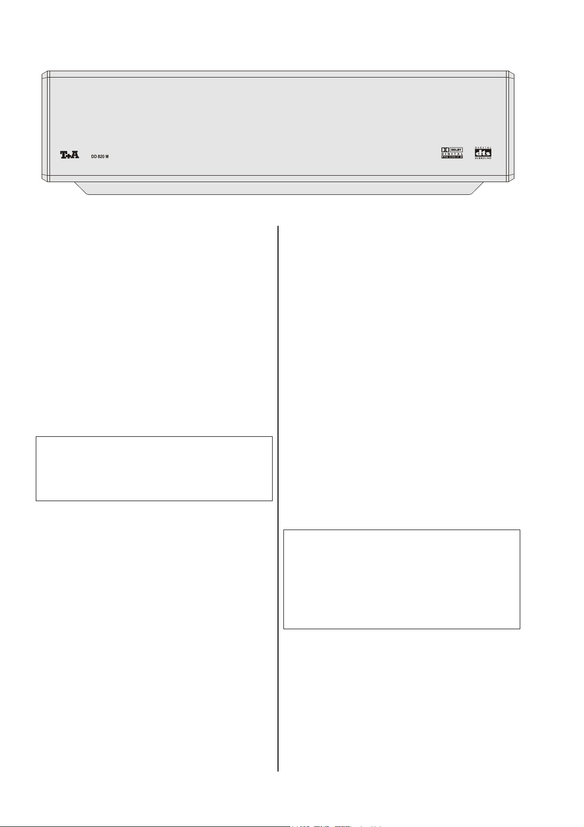
Front des DD 820 M
Allgemeines
Der digitale Surrounddecoder DD 820 M erweitert die
Stereoversion der M 820-Anlage zu einem hochwertigen 5.1 Kanal Heimkinosystem. Er erweitert die
Anschlussmöglichkeiten des M-Systems um zwei Bildund Toneingänge für den DVD Spieler DVD 820 M und
für einen Satelliten- bzw. Kabelreceiver (Set Top Box).
Der DD 820 M wird vollständig in die Bedienung des
M 820-Systems integriert und komplett über die
Systemfernbedienung F6 bedient.
Informationen über den Betriebszustand des DD 820 M
werden auf dem zentralen Anlagendisplay des PT 820 M
dargestellt.
Zusätzlich verfügt der DD 820 M über ein BildschirmMenü (On-Screen-Menü), mit dessen Hilfe Bedien- und
Einstellfunktionen übersichtlich auf dem Bildschirm eines
angeschlossenen TV-Gerätes angezeigt werden.
Hinweis:
In dieser Anleitung wird nur der Surrounddecoder
DD 820 M beschrieben. Für die Bedienung, Installation,
Aufstellung und Inbetriebnahme der Gesamtanlage
beachten Sie bitte die entsprechenden Bedienungsanleitungen der anderen Anlagenkomponenten.
Bedienung
Ein-/Ausschalten
Der DD 820 M wird automatisch zusammen mit den
anderen Komponenten des M-Systems ein- und ausgeschaltet.
Stereo und Surround Betriebsart
Das M-System verfügt mit dem PT 820 M und dem
PA 820 M über einen hochwertigen audiophilen Stereo-
verstärker, der vom Decoder DD 820 M zu einem 5.1
Kanal Surround- und Heimkinosystem komplettiert wird.
Im analogen Stereobetrieb übernimmt der PT 820 M
sämtliche Einstell- und Regelfunktionen, der DD 820 M
ist vollständig aus dem Signalweg verbannt.
Im Surroundbetrieb übernimmt der DD 820 M die
Funktion des zentralen Steuergerätes. Der Vorteil dieser
Konzeption liegt in der hohen Störfreiheit und der erreichten Musikalität des reinen analogen Stereobetriebs,
der mit normalen Surroundkonzepten in dieser Qualität
kaum erreichbar wäre.
Weitere Erläuterungen und Hintergründe zu diesem
Thema finden sich auch im Kapitel 'Das
System'.
Surround
Hinweis:
Da zur Erzielung höchster Klangqualität der Surrounddecoder DD 820 M im Analog-Stereobetrieb nicht im
Betrieb ist, stehen in dieser Betriebsart auch nicht die in
dieser Anleitung beschriebenen 'On-Screen-Menüs' des
DD 820 M zur Verfügung.
Einstellungen im Stereobetrieb erfolgen wie bei M-Anlagen ohne DD 820 M über das Gerätedisplay des
PT 820 M.
6
Page 7
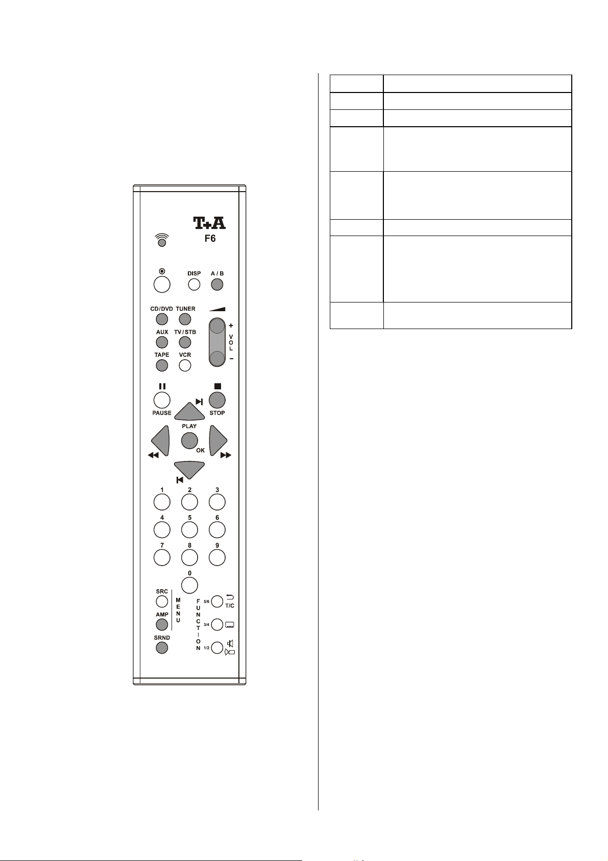
Fernbedienung des Surround Decoders
Allgemeines
Für die Bedienung der wichtigen Grundfunktionen des
Decoders, wie z. B. die Wahl der Ton- und Bildquelle,
oder die Einstellung der Lautstärke, stehen direkte
Taster auf der Systemfernbedienung F6 zur Verfügung.
Auf der Abbildung sind die Taster '
für die Fernbedienung des Gerätes benötigt werden. Alle
anderen Taster wirken nicht auf den Decoder.
' markiert, die
Wählt den DVD 820 M als Quelle.
Wählt den Tuner als Quelle.
Wählt den Eingang AUX/PH als Quelle.
Wählt einen der Eingänge TV oder STB
(Sat-Receiver) als Quelle. Wiederholtes
Antippen dieser Taste schaltet zwischen TV
und STB um.
Wählt einen der Eingänge TAPE 1
(CC 820 M) oder TAPE 2 als Quelle.
Wiederholtes Antippen dieser Taste schaltet zwischen TAPE 1 und TAPE 2 um.
Wippe zur Lautstärkeregelung.
Kurz antippen schaltet die Lautsprecherausgänge nacheinander:
A B A/B
Lange drücken schaltet die Lautsprecher-
ausgänge aus.
Schaltet zwischen Surround-Betrieb und
Stereo-Betrieb um.
Zusatzfunktionen
Seltener benötigte Funktionen des Decoders, die
üblicherweise nicht täglich verändert werden (wie z. B.
Klangregelung oder Surround-Betriebsart), werden über
ein Bildschirm-Menü ('Haupt-Menü') bedient. Die einzelnen Funktionen des Haupt-Menüs sind im folgenden
Kapitel detailliert beschrieben.
Grundeinstellungen
Grundeinstellungen und Konfiguration des Decoders, die
nur bei der ersten Inbetriebnahme oder grundsätzlichen
Änderungen an der Anlage vorgenommen werden
müssen, sind über das Konfigurations-Menü zugänglich
und im Kapitel 'System Konfiguration' näher erläutert.
7
Page 8
Menü Steuerung
Der DD 820 M verfügt über ein 'Hauptmenü' zur Bedienung seltener benötigter Zusatzfunktionen und ein
'Konfigurationsmenü' für die Grundeinstellung und
Konfiguration des Gerätes.
Das 'Konfigurationsmenü' wird in der Regel nur bei der
ersten Inbetriebnahme oder bei grundsätzlichen
Änderungen an der Anlage benötigt.
Alle Menüs werden seitenweise auf dem Bildschirm
eines angeschlossenen TV-Gerätes dargestellt. Zusätzlich wird der gerade gewählte Menüpunkt auch auf dem
Display des PT 820 M dargestellt. Damit können die
Menüs grundsätzlich auch ohne eingeschalteten TVBildschirm bedient werden.
Bedienung der Menüs
Die Menüsteuerung des DD 820 M erfolgt mit den Fernbedienungstastern
und
.
Hinweis:
, , , , ,
Kurz antippen:
öffnet und schließt das Haupt-Menü.
Ca. 3 Sekunden gedrückt halten:
öffnet das Konfigurationsmenü.
Wählt einen Menüpunkt aus.
Verändert die Einstellung des gerade
gewählten Menüpunktes.
Aktivierung der gerade gewählten Funktion.
Schließt das Menü.
Bei Verwendung der Systemfernbedienung F1 kann auch die gelbe
Tasters benutzt werden.
-Wippe anstelle des
-
8
Page 9
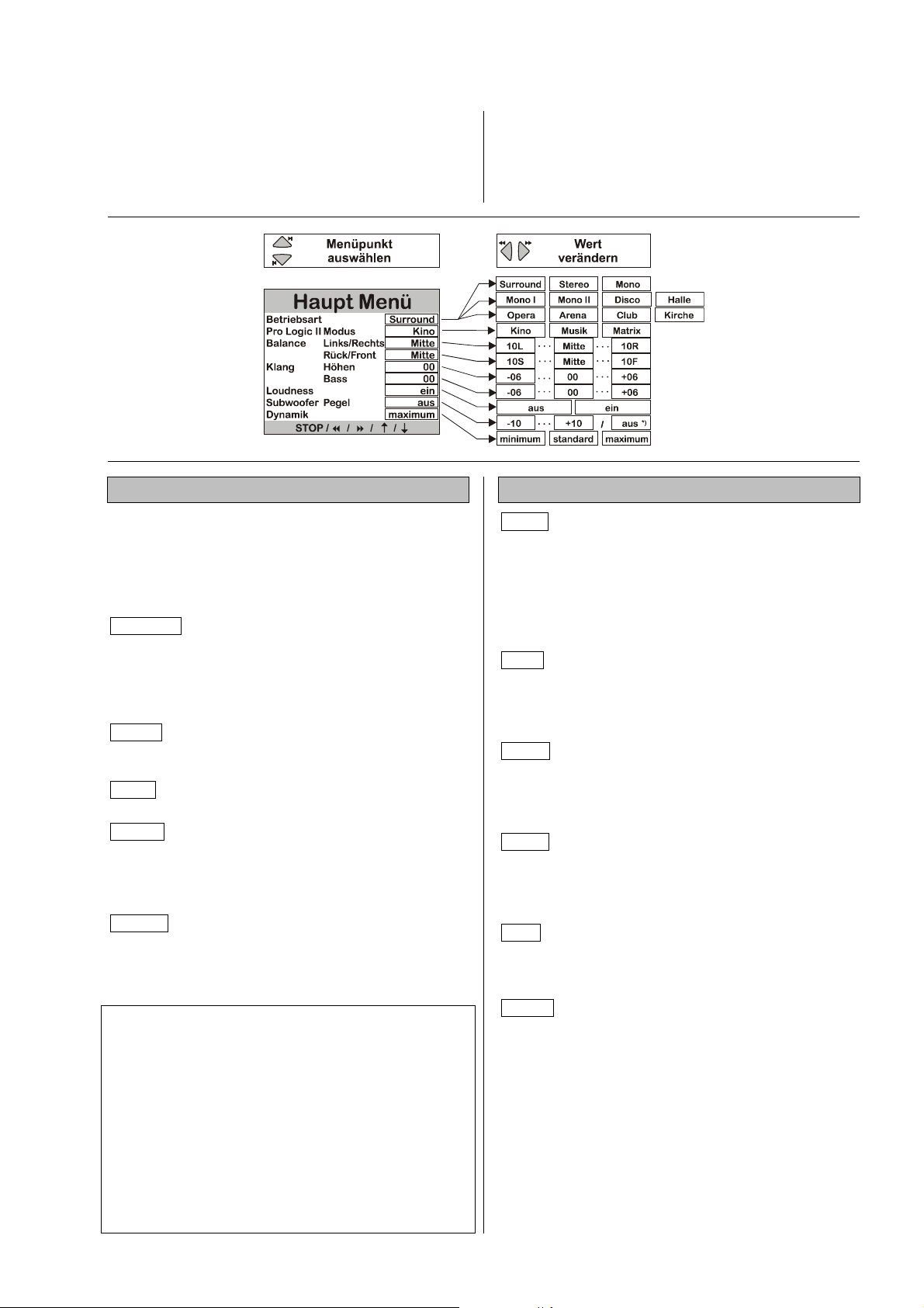
Haupt Menü
Das 'Haupt Menü' wird durch kurzes Antippen des
-Tasters geöffnet und auf dem Bildschirm darge-
stellt. Mit den / Tastern wird ein Menüpunkt an-
gewählt und mit den / Tastern wird die Ein-
stellung verändert.
Betriebsart:
In diesem Menüpunkt können Sie die Wiedergabebetriebsart oder die Klangfelder des Decoders auswählen.
Der Decoder 'merkt sich' die Einstellung für jeden
Eingang und benutzt beim Eingangs-Umschalten
wieder die Betriebsart, die zuletzt für den jeweiligen
Eingang eingestellt war!
Surround Ein digitales Mehrkanal-Signal wird anhand
seiner Codierung erkannt, decodiert und auf alle Ausgangskanäle weitergeleitet. Die aktuelle Decoder-Betriebsart wird im Anlagendisplay angezeigt. Für analoge
Signale wendet der Decoder immer die Dolby Pro Logic
Decodierung an.
Stereo Ein Mehrkanal-Signal wird in ein Stereo-Signal
verwandelt, d. h. alle Kanäle werden auf die Haupt(Main-) Lautsprecher links und rechts gemischt.
Mono Alle Kanäle werden auf den Center-Lautsprecher
gemischt.
Mono I Betriebsart für Fernseh-Zweikanalton
Auf Kanal I wird in der Regel die Synchronfassung gesendet. Das Signal von Kanal I wird auf dem CenterLautsprecher *) wiedergegeben; Kanal II (Originalfassung) wird unterdrückt.
Mono II Betriebsart für Fernseh-Zweikanalton
Auf Kanal II wird in der Regel die Originalfassung gesendet. Das Signal von Kanal II wird auf dem CenterLautsprecher *) wiedergegeben; Kanal I (Synchronfassung) wird unterdrückt.
Hinweise:
*) Wenn kein Centerlautsprecher vorhanden ist (siehe
'Lautsprecher Menü'), wird der Centerkanal auf den
linken und rechten Hauptlautsprecher gemischt.
Nicht alle Signalquellen (DVDs, CDs usw.), die Dolby
Digital oder dts Digital Surround codiert sind, enthalten
die vollständigen 5.1 Informationen. Selbst wenn ein
Kanal im Display als vorhanden angezeigt wird, müssen
nicht ständig Tonsignale aus dem Lautsprecher
kommen.
Abhängig von der Lautsprecherwahl im 'Lautsprecher
Menü' können in jeder Wiedergabebetriebsart auch
Signale auf dem Subwooferkanal zur Verfügung stehen.
Das Menü kann jederzeit mit dem
Taster der Fernbedienung oder durch einen langen
Tastendruck des
beendet werden.
-Tasters an der Gerätefront
- bzw.
-
Klangfelder:
Disco Dieses Klangfeld eignet sich besonders für die
gleichmäßige Beschallung einer Tanzfläche mit Frontund Surround-Lautsprechern. Das Tonsignal wird ohne
Hallanteil oder Verzögerung mit gleicher Leistung auf
Front- und Surround-Lautsprecher gemischt. Die stark
konzentrierte Tonwiedergabe erzeugt eine unmittelbare,
energiegeladene Atmosphäre, die sehr gut für Partybetrieb geeignet ist.
Halle Halliger Konzertsaal mit Reflexionen aus allen
Raumrichtungen. Sehr gut geeignet für die Wiedergabe
großer Orchester oder die Live-Atmosphäre einer großen
Rockkonzerthalle - gut geeignet für sehr dynamische
Rockmusik.
Opera Dieses Programm kombiniert das ganze
Spektrum von klaren Stimmwiedergaben mit der vollen
Tonwiedergabe eines Orchesters ohne unnatürlichen
Nachhall. Zur besseren Orientierung ist der Raumklang
nach hinten etwas eingeschränkt.
Arena Klangbild mit enger Präsenz im vorderen Bereich. Kommentatoren und Dialoge sind auf dem Bildschirm lokalisiert. Die hinteren Hall-Anteile vermitteln den
Eindruck des Publikums im Stadion. Dieses Klangfeld ist
auch geeignet für TV-Shows und Musiksendungen.
Club Typische Jazzkeller-Atmosphäre, mit einem
Reflexionsmuster, das von großen Boden- und Wandflächen dominiert wird. Eignet sich auch gut für die
Simulation kleiner Hallen.
Kirche Nachbildung der akustischen Bedingungen
einer großen Kirche mit langem Nachhall. Dieses
Klangfeld ist besonders geeignet für sakrale Orgelmusik.
9
Page 10
ProLogic II Modus:
Subwoofer Pegel:
Dieser Menüpunkt ermöglicht die Anpassung des Dolby
ProLogic II Decoders an unterschiedliches ProgrammMaterial.
Kino für Filme
Musik für Musik
Matrix für Monoprogramm-Material
Balance Links/Rechts und Front/Rück:
Diese beiden Menüpunkte ermöglichen eine temporäre
Veränderung der Pegelbalance zwischen den Lautsprechern links/rechts bzw. vorn/ hinten, um eine zeitweilig ungünstige Hörposition auszugleichen. Die Pegelbalance kann in 1 dB-Schritten verändert werden. Der
aktuelle Wert wird jeweils angezeigt.
10L (Links) . . . . . 10R (Rechts)
10R (Rück) . . . . . 10F (Front)
Mitte (Neutralstellung)
Hinweis:
Für die wirkliche (Standard)-Hörposition muss zuvor die
Lautstärkebalance der Kanäle (Front, Surround und
Center) im 'LS Balance Menü' angeglichen worden sein!
Klang Höhen und Klang Bass:
Wenn der Subwoofer im 'Lautsprecher Menü' eingeschaltet ist, so kann dessen Pegel zwischen -10 (dB)
und +10 (dB) verändert werden, um die Lautstärke des
Subwoofers an die akustischen Verhältnisse des Hörraumes und die Lautstärke der anderen Kanäle anzugleichen.
Wenn der Subwoofer im 'Lautsprecher Menü' ausgeschaltet wurde, zeigt der Menüpunkt im 'Haupt Menü'
aus . Der Subwoofer-Pegel kann nun nicht verändert
werden!
Hinweis:
Die Lautstärkebalance zwischen den anderen Kanälen
(Front, Rear und Center) muss zuvor im 'LS Balance
Menü' angeglichen worden sein!
Subwoofer Lautstärke:
Um die Subwoofer Lautstärke einzustellen, muss erst im
'
PT
PT STEREO
STEREO
PTPT
Subwoofer so eingestellt werden, dass der Pegel
passend ist. Dann erst im '
sprecher Einmessung vornehmen und zum Schluss im
Hauptmenü den Subwoofer Pegel anpassen. Nur so
lässt sich gewährleisten, dass der Klang sowohl während
'
PT
PT STEREO
STEREO
PTPT
STEREO STEREO
Erläuterungen zum '
finden Sie im Kapitel 'Stereo und Surround Betriebs-
art'.
'-Modus die Lautstärke mit dem Regler am
STEREOSTEREO
SURROUND
' als auch '
SURROUND
SURROUNDSURROUND
Surround
Surround
SurroundSurround
PT
PT STEREO
STEREO
PTPT
STEREO STEREO
' optimal ist.
'- und '
'-Modus die Laut-
Surround
Surround
SurroundSurround
'-Modus
Diese beiden Menüpunkte ermöglichen eine temporäre
Veränderung der Höhen- bzw. Bass-Einstellung zur
Kompensation von Klangunterschieden des ProgrammMaterials. Die Einstellung wirkt auf allen Kanälen. Der
Regelbereich beträgt +/- 6 dB in 1 dB-Schritten. Der
aktuelle Wert wird jeweils angezeigt. 00 dB bedeutet
'Linearstellung'.
Hinweis:
Die genaue Klangeinstellung zur Kompensation von
ungünstigen Lautsprecherstandorten oder Raumeinflüssen muss zuvor im 'Klangsteller Menü' erfolgt sein!
Loudness:
Schaltet die lautstärkeabhängige Klangkorrektur
(LOUDNESS) abwechselnd ein und aus. Das Anzeigefeld des Decoders stellt den aktuellen Zustand jeweils
kurzzeitig im Klartext dar; eine dauerhafte Anzeige der
eingeschalteten Klangkorrektur erfolgt durch das Symbol im Displayfenster.
Dynamik:
Der Dynamikbereich ist der Lautstärkeunterschied
zwischen den leisesten und lautesten Passagen einer
Aufnahme. Die Originalvertonung eines Filmes besitzt in
der Regel einen sehr großen Dynamikbereich, der durch
den Decoder in vollem Umfang wiedergegeben werden
kann.
Leider eignet sich nicht jeder Hörraum für die Wiedergabe des vollen Dynamikumfangs. Gegebenenfalls muss
zu später Stunde auch auf Nachbarn Rücksicht genommen werden.
Deshalb kann der Dynamikbereich für Dolby Digitalcodierte Tonquellen in drei Stufen so reduziert werden,
dass ruhige Passagen (z. B. leise Gespräche) bei
geringerer Lautstärke etwas lauter wiedergegeben
werden, während laute Passagen (z. B. gewaltige Explosionen) in der Lautstärke etwas reduziert werden.
Die folgenden Dynamikbereiche sind wählbar:
minimum stark reduzierter Dynamikumfang, z. B. für
Wiedergabe zur Nachtzeit.
standard Standard, mittlere Komprimierungsstufe.
maximum Nutzung des maximalen Dynamikberei-
ches, den die Tonquelle zur Verfügung
stellt.
Hinweis:
Die Einstellung des Dynamikbereiches hat nur Auswirkung auf Dolby Digital-codierte Tonquellen!
10
Page 11

Installation
Inbetriebnahme
Sicherheitshinweise
In diesem Kapitel werden alle Dinge von grundsätzlicher Bedeutung für die Aufstellung und Inbetriebnahme beschrieben, die nicht für den täglichen Umgang mit dem Gerät relevant sind, die aber trotzdem vor dem ersten Gebrauch
gelesen und beachtet werden sollten.
11
Page 12
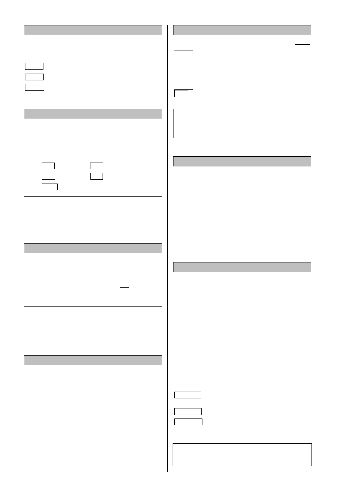
System Konfiguration
Im 'Konfigurations Menü' werden alle Audio- und
Video-Komponenten Ihrer Surround-Anlage optimal
aufeinander abgestimmt und an die akustischen Gegebenheiten Ihres Hörraumes angepasst.
Übersicht 'Konfigurations Menü'
Die Abstimmung wird nur bei der Installation der Anlage
durchgeführt oder wenn einzelne Komponenten der
Anlage ergänzt bzw. ausgetauscht werden. Das folgende
Diagramm zeigt den Aufbau der Menüstruktur.
Alle Menüs werden sowohl seitenweise auf dem Bildschirm eines angeschlossenen Fernsehgerätes als auch
zeilenweise auf dem Display des Gerätes dargestellt.
Die folgende Beschreibung der Menüpunkte erklärt die
Einstellmöglichkeiten und deren Auswirkungen.
12
Page 13

Konfigurations Menü
Die Bedienung erfolgt nur über die Fernbedienung F6.
Drücken Sie den
das 'Konfigurations Menü' zu öffnen. Mit den /
Tastern wird ein Menüpunkt angewählt und mit den
/ Tastern wird die Einstellung verändert.
-Tasters ca. 3 Sekunden, um
Bildschirm-Menü ein- / ausschalten:
Bei temporär durchgeführten Balance- oder Klangeinstellungen muss nicht unbedingt das 'Haupt Menü' auf
dem Bildschirm angezeigt und damit über den Film geblendet werden. In den meisten Fällen reicht die Darstellung auf dem Gerätedisplay völlig aus. In diesem
Menüpunkt kann die Bildschirmdarstellung ein- und ausgeschaltet werden.
aus Das 'Haupt Menü' wird nicht auf dem Bild-
schirm sondern nur zeilenweise auf dem Gerätedisplay angezeigt.
Das Menü kann jederzeit mit dem
Taster beendet werden.
- bzw.
-
Bildnorm:
In diesem Menü wird die Bildnorm für den TV-Ausgang
eingestellt.
Eingänge:
Das 'Eingänge Menü' dient dazu, den digitalen Eingang
für die Quelle STB zuzuweisen.
ein Das 'Haupt Menü' wird sowohl auf dem
Bildschirm als auch zeilenweise auf dem
Gerätedisplay angezeigt.
Bildschirmsprache:
Die Bildschirm-Menüs können auf dem Bildschirm in
verschiedenen Sprachen dargestellt werden. Die Bildschirmmenüs erscheinen in der ausgewählten Sprache.
Setup-Assistent:
Der Menüpunkt 'Setup Assistent' stellt eine Alternative
zum manuellen 'Lautsprecher Menü' dar. Ein Aufruf des
Assistenten führt zu einer automatisierten Routine zur
richtigen Einstellung der einzelnen Lautsprecherkanäle
des Surroundsystems.
Lautsprecher:
Das 'Lautsprecher Menü' ermöglicht die optimale Verteilung der Ausgangssignale auf die vorhandene Lautsprecheranlage. Darüber hinaus können die Lautsprecher exakt an die akustischen und räumlichen
Eigenarten Ihres Hörraumes angepasst werden.
13
Page 14
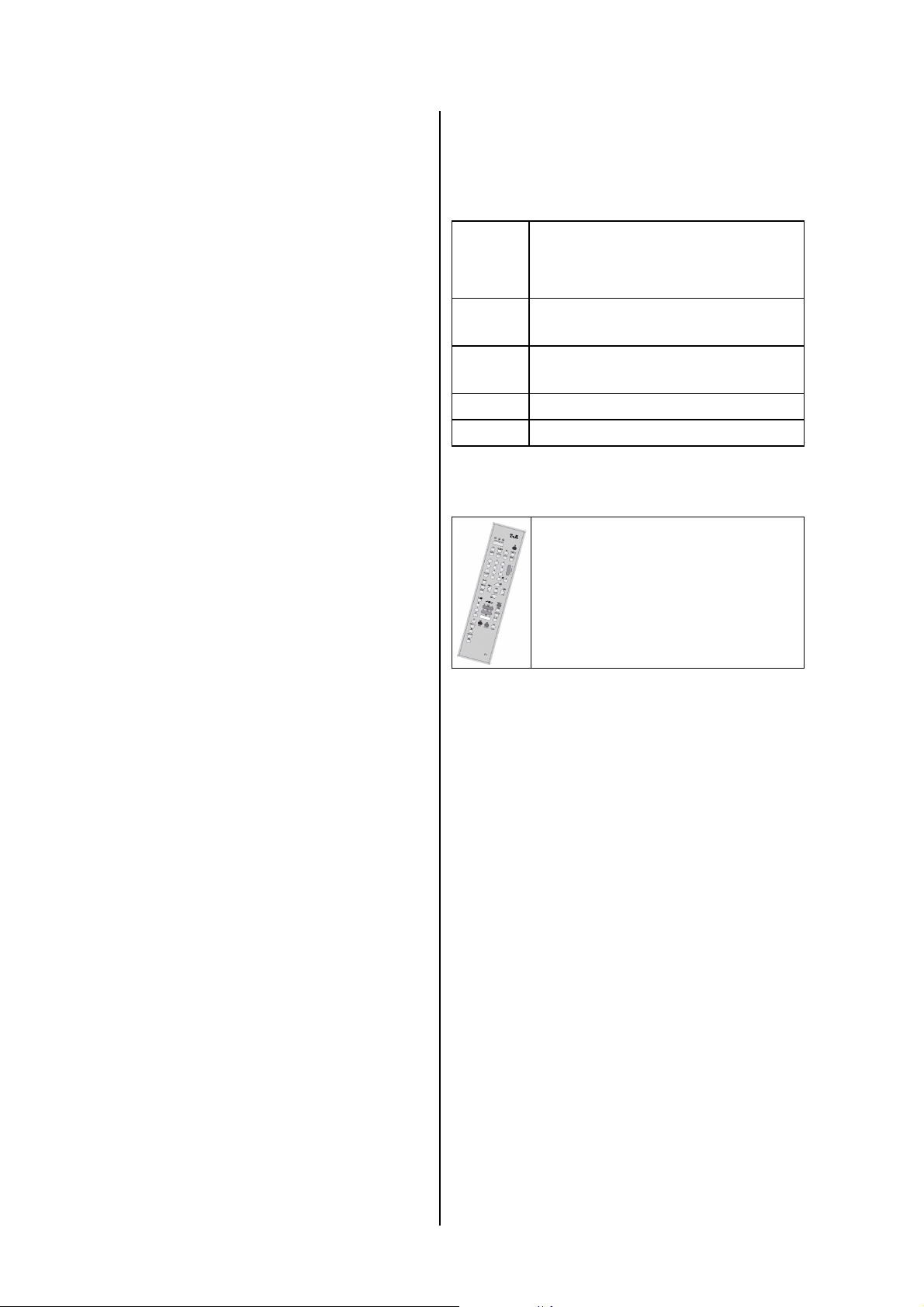
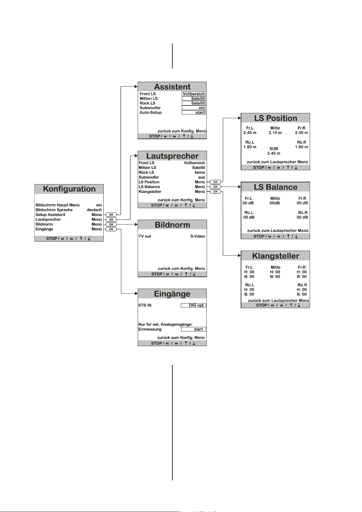
Assistent Menü
Mit dem Setup Assistenten bietet Ihnen eine
Hilfestellung bei der richtigen Einstellung Ihrer
Surroundanlage. Wenn Sie die unten beschriebenen
Schritte befolgen, wird der DD 820 M mit Hilfe des
mitgelieferten Messmikrofons eine automatische Einmessung Ihrer Lautsprecher vornehmen, die unter
normalen Hörraumbedingungen optimale Ergebnisse
liefert.
Front LS:
Mitten LS:
Folgende Voraussetzungen sollten für korrekte Messergebnisse erfüllt sein: eine freie Aufstellung des
Messmikrofons in der Nähe Ihres bevorzugten Hörplatzes
(z. B. auf dem Wohnzimmertisch oder auf einer
Sessellehne) und freier Sichtkontakt zwischen Mikrofon
und jedem Lautsprecher.
Schließen Sie zuerst das mitgelieferte Messmikrofon an
die rückwärtige CAL MIC.-Buchse des DD 820 M an.
Stellen Sie nun eine normale Abhörlautstärke ein.
Nach Aufruf des Setup-Assistenten erscheint das dargestellte Menü.
In der Spalte Pegel finden Sie die ermittelten und
eingestellten Pegelkorrekturen (Lautstärkeausgleich), in
der Spalte Dist. werden die ermittelten Lautsprecherentfernungen aufgelistet.
Rück LS:
Subwoofer:
Stellen Sie in der hinteren Spalte des Menüs zunächst
die Größen Ihrer Lautsprecher richtig ein (s. 'Laut-
sprecher Menü') und geben Sie an, ob ein Subwoofer
vorhanden ist oder nicht.
Auto-Setup:
Danach gehen Sie zum Menüpunkt 'Auto-Setup' und
aktivieren Sie den Punkt durch Drücken des
-Taster.
Um zu gewährleisten, daß die Einmessung korrekt
durchgeführt werden kann, muß zuerst die Lautstärke
optimal eingestellt werden. Dazu erzeugt der DD 820 M
auf dem vorderen linken Kanal ein Rauschsignal. Die
Bildschirmdarstellung zeigt in der Zeile 'Volume' den
aktuell eingestellten Lautstärkewert und blinkend
dahinter den zu drückende Taster an. 'VOL+' bedeutet,
daß die Lautstärke zu niedrig ist, bei 'VOL-' ist sie zu
hoch und nur bei Anzeige von 'OK' kann die Einmessung
durch Druck auf den
Nun wird der DD 820 M die automatische Einmessung
durchführen. Während der Einmessung hören Sie verschiedene Testsignale aus Ihren Lautsprechern.
Während der Messdauer sollten keine lauten Störgeräusche auftreten, da sonst die Ergebnisse verfälscht
werden können.
Über die gefundenen Einstellungen informiert Sie
laufend die Bildschirmdarstellung 'Auto Setup' auf Ihrem
TV-Gerät.
-Taster gestartet werden.
Beispiel für die Messwert-Anzeige
des Setup-Assistenten
Hinweise:
Sollte die Messung durch Störgeräusche beeinträchtigt
worden sein oder aus anderen Gründen unplausible
Messergebnisse aufgetreten sein, so kann die Messung
jederzeit erneut gestartet werden.
Die vom Assistenten ermittelten Entfernungen werden
anhand der akustischen Laufzeiten berechnet. Sie
können aufgrund von Signalverzögerungen in Ihren
Lautsprechern geringfügig von geometrischen Entfernungen abweichen.
Falls die automatische Einmessung aufgrund schwieriger
akustischer Verhältnisse in Ihrem Hörraum falsche Ergebnisse liefert, sollten Sie zunächst versuchen, durch
Variation der Mikrofonposition und / oder der Lautstärkeeinstellung ein besseres Ergebnis zu bekommen.
Sollte dies keinen Erfolg bringen und eine automatische
Einmessung daher nicht möglich sein, so können Sie die
Lautsprechereinstellung manuell über das 'Laut-
sprecher Menü' vornehmen.
14
Page 15
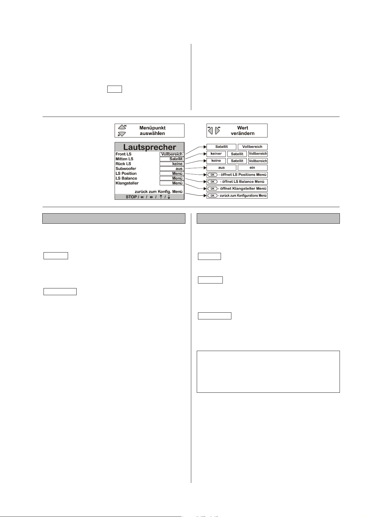
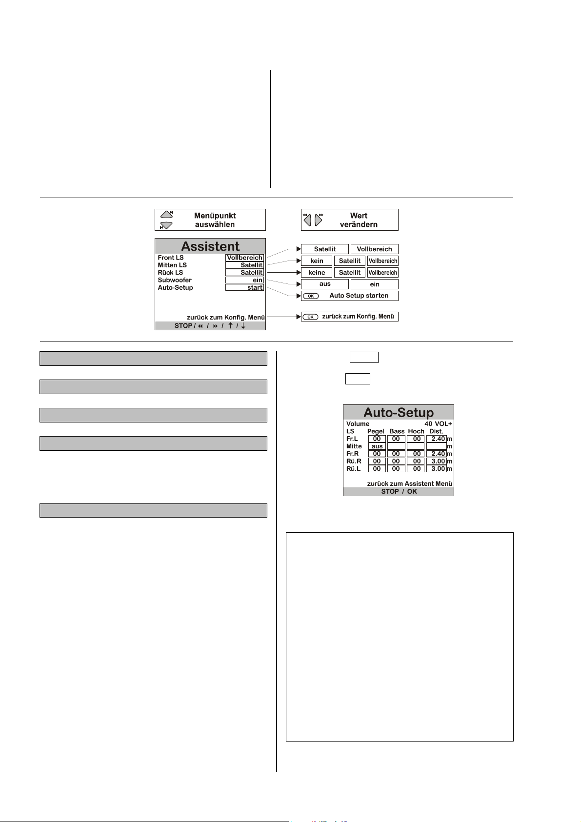
Lautsprecher Menü
Im 'Lautsprecher Menü' wird zunächst die Aufteilung
der Ausgangssignale optimal an die vorhandene Lautsprecheranlage angepasst.
Damit keine Toninformationen verloren gehen, wenn
nicht alle Lautsprecher (Center, Rear und Subwoofer)
vorhanden sind, müssen die fehlenden Komponenten im
'Lautsprecher Menü' als kein gekennzeichnet sein.
Das entsprechende Tonsignal wird dann auf die vorhandenen Kanäle verteilt (Downmix).
Front LS:
Einstellung der Größe und Bass-Wiedergabefähigkeit
der Hauptlautsprecher vorn links und rechts. Wählen Sie
folgende Einstellung:
*)
Die drei letzten Menüpunkte ermöglichen darüber hinaus
eine exakte Anpassung der Lautsprecher an die
akustischen und räumlichen Eigenarten Ihres Hörraumes.
Diese Einstellungen sollten nur bei der Erstinstallation
durchgeführt werden, bzw. wenn einzelne LautsprecherKomponenten ergänzt, umgestellt, ausgetauscht wurden
oder wenn sich die akustischen Verhältnisse Ihres Hörraumes verändert haben (z. B. durch neue Möbel, Teppiche, Vorhänge etc.).
Mitten LS:
Einstellung der Größe und Bass-Wiedergabefähigkeit
des Centerlautsprechers. Wählen Sie folgende Einstellung:
*)
Satellit für kleine Boxen, deren Basswiedergabe
naturgemäß nicht optimal ist. Die tieffrequenten Bass-Signale (unterhalb 80 Hz)
der Hauptkanäle werden , falls vorhanden,
auf den Subwoofer gemischt.
Vollbereich für größere Boxen. Der gesamte Fre-
quenzbereich wird uneingeschränkt über
die Hauptkanäle wiedergegeben.
keiner wenn kein Centerlautsprecher vorhanden
ist. Der Centerkanal wird auf den linken
und rechten Hauptlautsprecher gemischt.
Satellit für kleine Centerlautsprecher. Die tief-
frequenten Bass-Signale des Centerkanals
(unterhalb 80 Hz) werden auf die Hauptlautsprecher und, falls vorhanden, auf den
Subwoofer gemischt.
Vollbereich wenn der Centerlautsprecher ungefähr so
groß ist, wie die Hauptlautsprecher. Der
gesamte Frequenzbereich wird uneingeschränkt über den Centerkanal wiedergegeben.
*) Hinweis:
Wenn kein Centerlautsprecher vorhanden ist, sollten die
Hauptlautsprecher nicht zu weit vom Fernsehgerät entfernt, und symmetrisch dazu aufgestellt sein. Andernfalls
ist die Lokalisierung von Dialogen auf dem Bildschirm
sehr schlecht möglich.
15
Page 16

Rück LS:
Subwoofer:
Einstellung der Größe und Bass-Wiedergabefähigkeit
der Rück- (Rear-) Surround-Lautsprecher. Wählen Sie
folgende Einstellung:
keine wenn keine Surround-Lautsprecher vorhanden
sind. Die Surroundkanäle werden auf den
linken und rechten Hauptlautsprecher gemischt.
*)
Hinweis:
Eine echte Surround-Wiedergabe ist ohne Rück-Lautsprecher nicht möglich!
Satellit für kleine Surround-Lautsprecher. Die tief-
frequenten Bass-Signale der Surroundkanäle
(unterhalb 80 Hz) werden auf die Hauptlautsprecher und, falls vorhanden, auf den
Subwoofer gemischt.
Vollbereich wenn die Bass-Wiedergabe der Rück-
(Rear-) Surround-Lautsprecher sehr gut ist.
Der gesamte Frequenzbereich wird uneingeschränkt über die Surroundkanäle wiedergegeben.
In diesem Menüpunkt wird eingestellt, ob in der Lautsprecheranlage ein Subwoofer vorhanden ist. Wählen
Sie folgende Einstellung:
ein wenn ein Subwoofer vorhanden ist. Die Sig-
nale vom Basseffektkanal (LFE) sowie alle
anderen tieffrequenten Bass-Signale (unterhalb 80 Hz), die nicht vom Vollbereichslautsprecher wiedergegeben werden, gibt der
Subwooferkanal wieder.
aus wenn kein Subwoofer vorhanden ist. Die
Signale vom Basseffektkanal (LFE) sowie alle
anderen tieffrequenten Bass-Signale (unterhalb 80 Hz) werden auf die Hauptlautsprecher
gemischt.
Hinweis:
Falls der Subwoofer im 'Lautsprecher Menü' eingeschaltet wurde, so kann dessen Pegel im 'Haupt Menü'
zwischen -10 (dB) und +10 (dB) verändert werden, um
die Lautstärke des Subwoofers an die Lautstärke der
anderen Kanäle anzugleichen.
L
S Position:
*) Hinweis:
Um unsinnige Einstellungen zu vermeiden, sind nicht alle
Kombinationen (Front LS, Mitte und Rück LS) einstellbar. Im Folgenden sind Standardkombinationen aufgeführt, die jedoch individuell modifiziert werden können.
Standardkombinationen
1. Front, Mitte und Rück LS: ... Satellit
Subwoofer: ......................... ein
2. Front LS: ............................ Vollbereich
Mitte und Rück LS: ............ Satellit
Subwoofer: ......................... aus
3. Front und Rück LS:............. Vollbereich
Mitte: .................................. Vollbereich
oder... Satellit
Subwoofer: ......................... ein
Das Aktivieren dieses Menüpunktes führt in ein Menü zur
Festlegung der Lautsprecherpositionierung. Hier kann für
jeden Lautsprecher die richtige Entfernung zur Hörposition eingegeben werden. Auf diese Weise werden Laufzeitdifferenzen aufgrund unterschiedlicher Abstände zum
Hörplatz kompensiert (siehe 'LS Position Menü').
LS Balance:
Das Aktivieren dieses Menüpunktes führt in ein Menü
zum Einstellen der Pegelbalance zwischen allen Lautsprechern (siehe 'LS Balance Menü').
Klangsteller:
Das Aktivieren dieses Menüpunktes führt in ein Menü
zum Einstellen der Lautsprecher-Klangbalance (siehe
'Klangsteller Menü').
16
Page 17
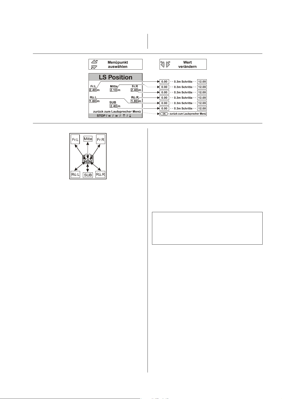
LS Position Menü
Im 'LS Position Menü' wird für jeden Lautsprecher die
richtige Entfernung zur Hörposition (in 0.3 m Schritten)
eingegeben.
Auf diese Weise werden Laufzeitunterschiede aufgrund
unterschiedlicher Abstände zum Hörplatz kompensiert.
Wie die Abbildung zeigt, sind die Eingabepositionen mit
den Auswahltastern in nachstehender Reihenfolge
zyklisch zu erreichen.
Nicht benutzte Ausgangskanäle (siehe 'Lautsprecher
Menü') sind nicht editierbar.
• Hauptlautsprecher Front links (Fr.L)
• Centerlautsprecher Front Mitte (Mitte)
• Hauptlautsprecher Front rechts (Fr.R)
• Surround-Lautsprecher hinten rechts (Rü.R)
• Surround-Lautsprecher hinten links (Rü.L)
• aktiver Subwoofer (Position beliebig) (Sub)
Messen Sie die Entfernung zwischen dem Hörplatz und
den vorhandenen Lautsprechern. Geben Sie die ermittelten Abstände ein.
Stellen Sie die gemessene Entfernung mit den Veränderungstastern in Schritten von 0,3 m ein.
Hinweis:
Der maximale Abstand eines Lautsprechers von der
Hörposition beträgt 12 m. Noch größere Entfernungen
sind aus akustischen Gründen nicht zu empfehlen – deswegen können deren Laufzeiten durch das System nicht
mehr kompensiert werden.
17
Page 18
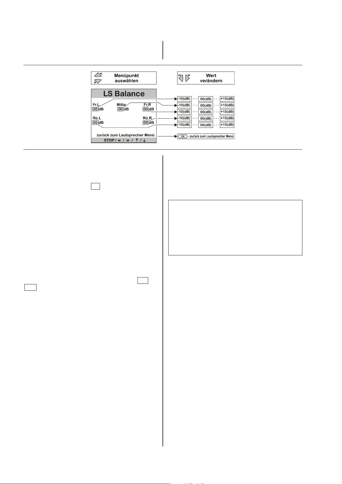
LS Balance Menü
Damit der Decoder ein ausgewogenes Klangbild liefert,
müssen die Lautstärkepegel der einzelnen Kanäle sorgfältig aufeinander abgestimmt werden.
Mit dem Aktivieren des 'LS Balance Menüs' ertönt im
linken Hauptlautsprecher zwei Sekunden lang ein
Rauschen. Die Eingabeposition befindet sich hinter dem
ersten Menüpunkt
'Fr.L: 00 '.
Wie die Abbildung zeigt, wird das Rauschen auf folgenden Kanälen in zyklischer Folge für jeweils ca. zwei
Sekunden wiedergegeben:
• Hauptlautsprecher Front links (Fr.L)
• Centerlautsprecher Front Mitte (Mitte)
• Hauptlautsprecher Front rechts (Fr.R)
• Surround-Lautsprecher hinten links (Rü.R)
• Surround-Lautsprecher hinten links (Rü.L)
Nicht benutzte Ausgangskanäle (siehe 'Lautsprecher
Menü') werden übersprungen.
Während das Rauschen auf einem Kanal ertönt, wird die
zugehörige Eingabeposition angezeigt. Mit den Veränderungstastern kann der Wert im Bereich von -10 bis
+10 korrigiert werden. Die Änderung wird sofort hörbar.
Nach der Lautstärkekorrektur rauscht der Kanal noch
ca. zwei Sekunden weiter; dann geht das Rauschen auf
den nächsten Kanal über. Die Eingabeposition wandert
mit.
Das 'LS Balance Menü' dient zur genauen Einpegelung
aller Kanäle.
Statt durch die automatische Weiterschaltung kann der
zu korrigierende Kanal und damit die Eingabeposition
auch mit den Auswahltastern wie gewünscht angewählt
werden.
Stellen Sie alle Kanäle auf einen möglichst gleichen
Lautstärke-Eindruck ein!
Hinweise:
Da das Rauschen zur Beurteilung der Basslautstärke
nicht geeignet ist, benutzen Sie zur Lautstärkeanpassung des Subwooferkanals im 'Haupt Menü' den
Menüpunkt 'Subwoofer Pegel'.
Der Pegel eines jeden Kanals wird für die SurroundWiedergabe gespeichert und ist für alle SurroundBetriebsarten gültig.
18
Page 19
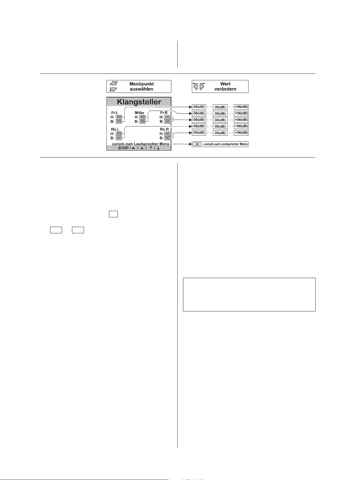
Klangsteller Menü
Der Decoder ist mit einer aktiven Klangregelung (+/-6dB)
ausgestattet. Diese dient zur Kompensation von
Raumeinflüssen oder ungünstigen Lautsprecherstandorten auf die Wiedergabequalität.
Wählen Sie zunächst eine Tonquelle, mit der Sie die
Klangeinstellung durchführen möchten. Die Tonquelle
sollte auf allen Kanälen aktiv sein, damit die Veränderung der Klangeinstellung in einem möglichst
realistischen Klangbild unmittelbar hörbar wird.
Nach dem Aktivieren dieses Menüpunktes befindet sich
die Eingabeposition hinter dem ersten Menüpunkt
'Fr.L H: 00 '.
Mit den Veränderungstastern kann der Wert im Bereich
von –06 bis +06 verändert werden. Die Änderung wird
sofort hörbar.
Die Eingabeposition wird mit den Auswahltastern wie
gewünscht angewählt.
Wie die Abbildung zeigt, sind die Eingabepositionen
zyklisch in nachstehender Reihenfolge zu erreichen.
Nicht benutzte Ausgangskanäle (siehe 'Lautsprecher
Menü') sind nicht editierbar.
Die Klangeinstellung wird für alle benutzten Ausgangskanäle separat durchgeführt, um unterschiedlichen Aufstellungsbedingungen Rechnung tragen zu können.
• Hauptlautsprecher Front links Höhen (H)
• Hauptlautsprecher Front links Bass (B)
• Centerlautsprecher Front Mitte Höhen (H)
• Centerlautsprecher Front Mitte Bass (B)
• Hauptlautsprecher Front rechts Höhen (H)
• Hauptlautsprecher Front rechts Bass (B)
• Surround-Lautsprecher hinten rechts Höhen (H)
• Surround-Lautsprecher hinten rechts Bass (B)
• Surround-Lautsprecher hinten links Höhen (H)
• Surround-Lautsprecher hinten links Bass (B)
Stellen Sie auf allen Kanälen solche Werte für Höhen (H)
und Bässe (B) ein, dass sich ein ausgewogenes Klangbild ergibt.
Hinweis:
Nach der Klangeinstellung wird empfohlen, das
'LS Balance Menü' erneut aufzurufen, um die Pegelbalance aller Kanäle noch einmal zu überprüfen und ggf.
zu korrigieren.
19
Page 20

Bildnorm Menü
Eine optimale Bildwiedergabe ist nur dann gewährleistet,
wenn die Bildnormen aller Video-Komponenten aufeinander abgestimmt sind und Kabel verwendet werden
(SCART, Video-Coax), die der Bildnorm entsprechen. Im
'Bildnorm Menü' wird für den TV-Ausgang des
Decoders die Bildnorm entsprechend der Fähigkeiten
des angeschlossenen Gerätes eingestellt. Viele AVQuellgeräte stellen das Bildsignal in verschiedenen Bildnormen (Video, S-Video) zur Verfügung. Die gewünschte
Bildnorm muss häufig in einem Gerätemenü des AVQuellgerätes eingestellt werden. Beachten Sie dazu die
Betriebsanleitung des Quellgerätes und des Fernsehgerätes.
Auf dem Markt existiert eine Vielzahl unterschiedlicher
Bildnormen, die jedoch nicht von allen AV-Quellgeräten
und Fernsehgeräten unterstützt werden. Der Decoder ist
ausgelegt für die am weitesten verbreiteten Bildnormen
Video und S-Video.
TV out:
S-Video Für Fernsehgeräte mit S-Video-Anschluss.
Video Für Fernsehgeräte mit Video-Anschluss.
20
Page 21
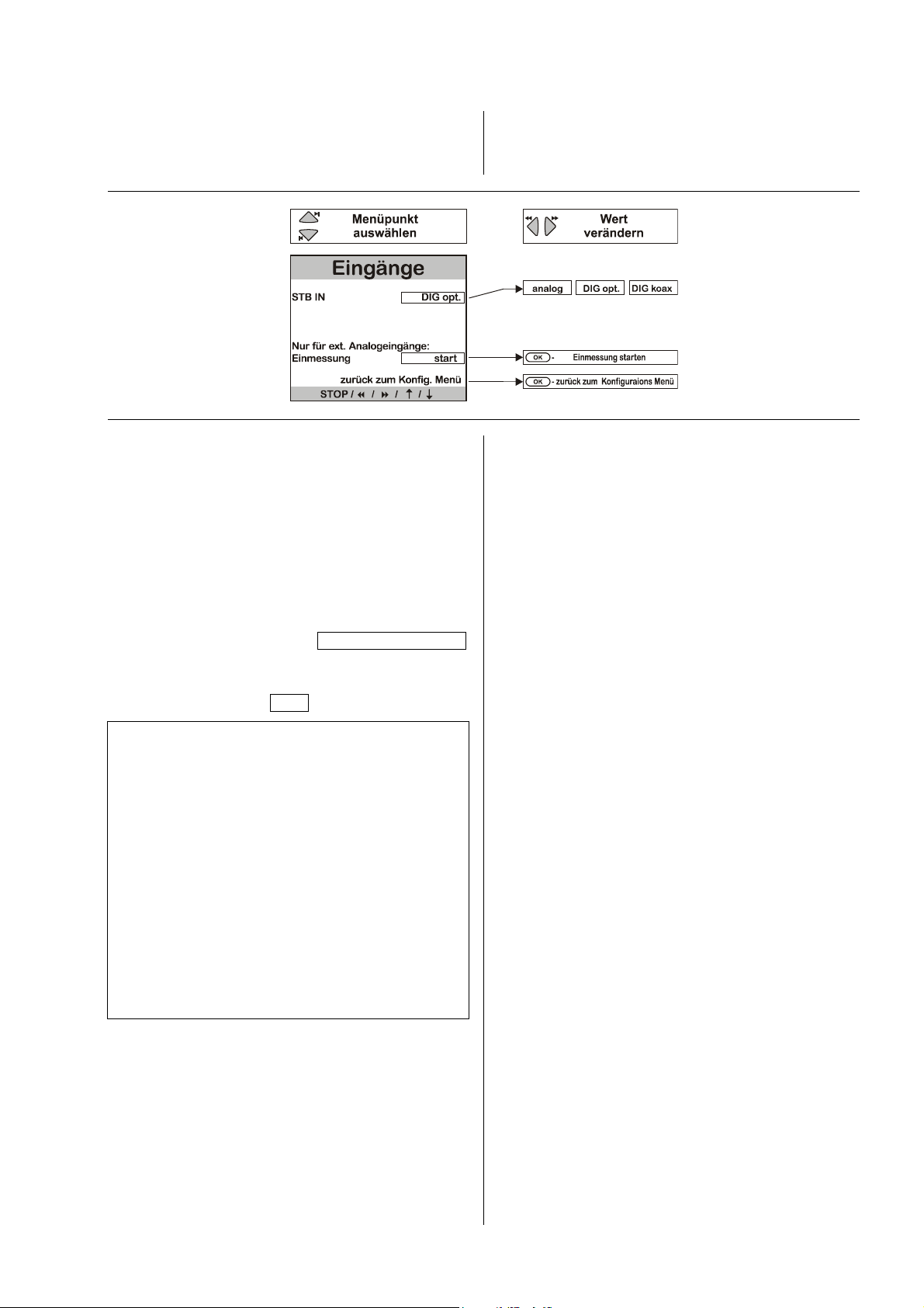
Eingänge Menü
In diesem Menü kann eingestellt werden, ob für den
SAT-Receiver (STB) der analoge Toneingang (L, R) oder
einen der digitalen Eingänge Digital IN optisch oder
Digital IN koax verwendet werden soll.
Einmessung:
Die bestmögliche Wiedergabequalität bei externen Quellgeräten mit Analogton wird erreicht, wenn der
Analog / Digital-Wandler des DD 820 M optimal an den
Ausgangspegel des Quellgerätes angepasst ist.
Zur Anpassung besitzt der DD 820 M eine automatische
Einmessfunktion. Zur Einpegelung gehen Sie bitte wie
folgt vor:
1. Gewünschtes analoges Audio- oder AV-Quellgerät
wählen und eine Fortissimo-Passage anspielen.
2. 'Eingänge Menü' aufrufen Einmessung starten
ansteuern und den
3. Solange der Einmessvorgang läuft, wird das auf dem
Bildschirm angezeigt: läuft .
-Taster drücken.
Hinweise:
Die automatische Einmessung steht für alle externen
analogen Audio- und AV-Quellgeräte (TAPE 1,
TAPE 2, AUX/TV, AUX/PHONO, STB [wenn analog]) zur
Verfügung. Sie sollte für alle an diese Eingänge angeschlossenen Geräte durchgeführt werden.
Der eingebaute Tuner ist bereits optimal eingepegelt, so
dass eine Einmessung dieses Quellgerätes nicht möglich
ist.
Wenn ein Quellgerät bei sehr lauten Passagen trotz
Einmessung gelegentlich übersteuert (verzerrt), so erscheint im Gerätedisplay kurz die Meldung:
'
O V E R L O A D
O V E R L O A D'.
O V E R L O A DO V E R L O A D
Der Analog / Digital-Wandler sollte dann auf dieses
Quellgerät neu eingemessen werden.
Diese Pegelanpassung wirkt nicht im '
PT
PT stereo
stereo
PTPT
stereostereo
'-Modus.
21
Page 22

Anschlusselemente
SUBWOOFER OUTPUT
Subwoofer-Ausgang (Anschluss an den PA 820 M).
Lautsprecherklemmen
REAR (R)
Hier wird die hinten (engl. rear) rechts stehende
Surround-Lautsprecherbox angeschlossen.
CENTER
Hier wird der vorn mittig zwischen den Hauptlautsprechern stehende Centerlautsprecher angeschlossen.
(CINCH)
Netzeingang
In diese Buchse wird das Netzkabel eingesteckt. Beim
Netzanschluss sind unbedingt die Hinweise in den
Kapiteln 'Installation, Inbetriebnahme, Sicherheitshin-
weise' zu befolgen.
M
LINK
Steuerschnittstelle zum Anschluss an den -Verstärker PA 820 M.
REAR (L)
Hier wird die hinten (engl. rear) links stehende SurroundLautsprecherbox angeschlossen.
Hinweis:
Für die Benutzung außerhalb von Ländern der EU können
die roten/schwarzen Stopfen aus den
Lautsprecherklemmen entfernt werden. Der Anschluss der
Lautsprecher kann dann mit Bananensteckern erfolgen.
Die Stopfen sind in die Klemmen nur eingesteckt. Sie
können mit einem geeigneten Werkzeug (z. B.
Messerklinge) nach hinten aus der Klemme gelöst werden.
Lüfter
Die intelligente Mikroprozessor-Lüftersteuerung des
DD 820 M erfasst laufend alle Betriebsparameter der
Endstufen und des Netzteiles.
Aus den Temperaturdaten, die an mehreren Stellen gemessen werden, sowie den Belastungs- und Ausgangspegeldaten wird ein Bedarfsprofil für die Lüfterleistung
errechnet und die Lüfterleistung entsprechend in drei
Stufen geregelt.
Durch diese Regelung ist der DD 820 M in der Lage,
über mehrere Stunden problemlos hohe Ausgangspegel
zu liefern ohne zu überhitzen.
Andererseits wird die Lüfterleistung bei leisen Musikpassagen reduziert. Dadurch werden die Endstufen auf
ihrer klanglich optimalen Betriebstemperatur gehalten
und zudem wird das Lüftergeräusch minimiert.
DIGITAL IN
Eingangsbuchsen zum Anschluss einer Settopbox mit
koaxialen oder optischen Digitalanschluss.
SETTOPBOX-INPUT
Eingangsbuchsen zum Anschluss einer Settopbox mit
S-Video und Analog-Cinch-Anschluss.
TV-OUTPUT
Ein-/Ausgangsbuchsen zum Anschluss eines Fernsehgerätes mit S-Video-Anschluss.
Tonausgang für Frontkanäle
(zum PA 820 M)
Stereotoneingang
DVD
Buchse zum Anschluss eines DVD 820 M.
LINK
(vom PT 820 M)
Der Lüfter darf auf keinen Fall durch Kabel
o. ä. blockiert werden. Die Lüfterflügel
müssen ungehindert drehen können.
CAL.-MIC.
Eingang für ein Mikrofon zur Kalibrierung der Lautsprecherpegel (s. Kapitel 'Assistent Menü').
22
Page 23

Sicherheitshinweise
Alle in diesem Gerät verwendeten Bauteile entsprechen
den geltenden deutschen und europäischen Sicherheitsnormen und –standards.
Eine genaue Qualitätsprüfung aller Materialien, die
sorgfältige Produktion, sowie die vollautomatische,
rechnergesteuerte Endkontrolle eines jeden Gerätes
gewährleisten die hohe Produktqualität und die Einhaltung aller Spezifikationen.
Zu Ihrer eigenen Sicherheit sollten Sie bitte unbedingt
diese Betriebsanleitung vollständig lesen und insbesondere die Aufstellungs-, Betriebs- und Sicherheitshinweise
genau befolgen.
Das Gerät ist so aufzustellen, dass eine Berührung
sämtlicher Geräteanschlüsse (insbesondere durch
Kinder) ausgeschlossen ist. Die Hinweise und Angaben
im Kapitel 'Installation, Inbetriebnahme, Sicherheits-
hinweise' sind unbedingt zu beachten!
Die für das Gerät erforderliche Stromversorgung ist dem
Aufdruck an der Netzgerätebuchse zu entnehmen. An
andere Stromversorgungen darf das Gerät nicht angeschlossen werden. Bei längerer Nichtbenutzung sollte
der Netzstecker des Gerätes aus der Steckdose gezogen werden.
Netzkabel müssen so verlegt werden, dass keine Gefahr
der Beschädigung (z. B. durch Trittbelastung oder durch
Möbelstücke) besteht. Besondere Vorsicht ist dabei an
den Steckern, Verteilern und an den Anschluss-Stellen
des Gerätes geboten.
Durch die Lüftungsschlitze dürfen keine Flüssigkeiten
oder Fremdkörper in das Gerät gelangen. Schützen Sie
das Gerät vor Tropf- und Spritzwasser und stellen Sie
keine Blumenvasen oder andere Gefäße mit Flüssigkeiten auf das Gerät. Im Inneren führt das Gerät Netzspannung, es besteht die Gefahr eines tödlichen elektrischen Schlages. Auf den Netzstecker darf keine übermäßige Krafteinwirkung ausgeübt werden.
Achtung!
Der DD 820 M wird über die M
PT 820 M ein-/ausgeschaltet. Auch im ausgeschalteten Zustand bleiben einige Teile des Gerätes mit
der Netzspannung verbunden. Wenn das Gerät
längere Zeit nicht benutzt wird (z. B. Urlaub), ist es
vorteilhaft, das Gerät vom Netz zu trennen. Dazu
muss der Netzstecker gezogen werden.
LINK
Schnittstelle vom
Wie alle Elektrogeräte so sollte auch dieses Gerät nicht
unbeaufsichtigt betrieben werden. Es ist darauf zu
achten, dass es für kleine Kinder unerreichbar ist.
ACHTUNG !
Reparaturen und das Auswechseln von Sicherungen
sind von einer autorisierten -Fachwerkstatt durchzuführen.
Außer den in der Betriebsanleitung beschriebenen
Handgriffen dürfen vom Benutzer keinerlei Arbeiten am
Gerät vorgenommen werden.
Bei Beschädigungen oder bei Verdacht auf eine nicht
ordnungsgemäße Funktion des Gerätes sollte sofort der
Netzstecker gezogen und das Gerät zur Überprüfung in
eine autorisierte Fachwerkstatt gegeben werden.
Überspannungen im Stromversorgungsnetz, dem Kabelnetz oder auf Antennenanlagen, wie sie z. B. bei
Gewittern (Blitzschlag) oder statischen Entladungen
auftreten können, stellen eine Gefährdung für das Gerät
dar.
Spezielle Vorschaltgeräte, wie Überspannungsprotektoren oder die 'Power Bar' Netzanschlussleiste,
bieten einen gewissen Schutz vor Gerätebeschädigungen aus o. g. Gründen.
Eine absolute Sicherheit vor Beschädigung durch Überspannungen kann aber nur eine vollständige Trennung
des Gerätes vom Netz und den Antennenanlagen gewährleisten.
Ziehen Sie zur Trennung sämtliche Netz- und Antennenstecker Ihrer HiFi Anlage bei Überspannungsgefahr
(z. B. bei heraufziehenden Gewittern) aus den Steckdosen.
Sämtliche Netzversorgungs- und Antennenanlagen, an
die das Gerät angeschlossen wird, müssen den geltenden Bestimmungen entsprechen und fachgerecht von
einem zugelassenen Installationsbetrieb ausgeführt sein.
Das Gerät darf nur vom qualifizierten
Fachmann geöffnet werden.
Hinweis:
Viele Versicherungsgesellschaften bieten im Rahmen
der Hausratversicherung eine Blitzschutzversicherung für
Elektrogeräte an.
23
Page 24

Bestimmungsgemäßer Gebrauch
Das Gerät ist ausschließlich zur Ton- und/oder Bildwiedergabe im Heimbereich in trockenen Räumen unter
Berücksichtigung aller in dieser Anleitung gemachten
Angaben bestimmt.
Bei allen anderen Einsatzzwecken, insbesondere in
medizinischen oder sicherheitsrelevanten Bereichen, ist
vorher die Zulassung und Eignung des Gerätes für
diesen Einsatz mit dem Hersteller abzuklären und
schriftlich genehmigen zu lassen.
Geräte mit Rundfunk- oder Fernsehempfangsteilen
dürfen im Rahmen der gültigen 'Allgemeingenehmi-
gung für Ton- und Fernseh- Rundfunkempfänger',
veröffentlicht im Amtsblatt des Bundesministers für Post
und Telekommunikation, in der Bundesrepublik Deutschland betrieben werden. Mit solchen Geräten dürfen nur
Aussendungen empfangen oder wiedergegeben werden,
die für die Allgemeinheit bestimmt sind. Der Empfang
oder die Wiedergabe anderer Aussendungen (z. B. des
Polizei- oder Mobilfunks) ist nicht gestattet.
Pflege des Gerätes
Vor Reinigungsarbeiten am Gerät ist der Netzstecker zu
ziehen.
Die Oberflächen des Gerätes sollten zur Reinigung nur
mit einem weichen, trockenen Tuch abgewischt werden.
Verwenden Sie keine scharfen Reinigungs- oder
Lösungsmittel!
Vor der Wiederinbetriebnahme muss sichergestellt sein,
dass keine Kurzschlüsse an den Anschluss-Stellen bestehen und dass alle Anschlüsse ordnungsgemäß sind.
Gerätezulassung und Konformität mit
EG-Richtlinien
Das Gerät entspricht im Originalzustand allen derzeit
gültigen deutschen und europäischen Vorschriften. Es ist
zum bestimmungsgemäßen Gebrauch in der EG zugelassen.
Durch das am Gerät befindliche Zeichen erklärt
die Konformität mit den EG-Richtlinien RL 89/336/EWG,
geändert durch RL 91/263/EWG und RL 93/68/EWG
sowie RL 73/23/EWG, geändert durch RL 93/68/EWG
und den daraus abgeleiteten nationalen Gesetzen.
Die unveränderte, unverfälschte Werksseriennummer
muss außen am Gerät vorhanden und gut lesbar sein!
Die Seriennummer ist Bestandteil unserer Konformitätserklärung und damit der Betriebszulassung des Gerätes!
Seriennummern am Gerät und in den original
Begleitpapieren (insbesondere den Kontroll- und
Garantiezertifikaten) dürfen nicht entfernt oder verändert
werden und müssen übereinstimmen.
Bei Verstoß gegen diese Bestimmungen gilt die Konformitätszusage von als widerrufen und ein Betrieb
des Gerätes innerhalb der EG ist untersagt und aufgrund
geltender EG und nationaler Gesetze unter Strafandrohung verboten.
Durch Umbauten am Gerät oder durch Reparaturen oder
sonstige Eingriffe von nicht von autorisierten Werkstätten oder sonstigen Dritten verliert das Gerät seine
Zulassung und Betriebserlaubnis.
An das Gerät dürfen nur original Zubehörteile oder
solche Zusatzgeräte angeschlossen werden, die ihrerseits zugelassen sind und allen geltenden gesetzlichen
Vorschriften genügen.
Auch mit Zusatzgeräten oder als Teil einer Anlage darf
das Gerät nur zu den im Abschnitt 'Bestimmungs-
gemäßer Gebrauch' genannten Anwendungen einge-
setzt werden.
24
Page 25

Anschluss des Fernsehgerätes und der Surroundboxen an den Decoder:
Führen Sie die Verkabelung der Komponenten gemäß
Anschluss-Schema wie folgt durch:
• Die Surround-Lautsprecher REAR RECHTS, REAR
LINKS und CENTER - falls vorhanden - an die ent-
sprechenden Ausgangsklemmen des Decoders anschließen.
• Falls vorhanden, den Eingang des aktiven Subwoofers
an SUB OUT anschließen.
• Mit einem S-Video / Video – Kabel und einem Adapter
verbinden Sie die TV-Buchse des Decoders mit Ihrem
Fernsehgerät.
• Zuletzt stellen Sie die Verbindung zur Netzspannung
her und schalten die Geräte ein.
• Zum Betrieb mit dem Decoder muss auch Ihr Fernseh-
gerät richtig konfiguriert werden. Zu den notwendigen
Einstellungen gehört:
Die Bildnorm muss entsprechend der angeschlossenen Quellgeräte gewählt werden.
Bei Quellgeräten, die unterschiedliche Bildnormen zur
Verfügung stellen, und Fernsehgeräten, die nicht
Multinorm-fähig sind, muss ggf. für alle Geräte die
Standard-Video-Norm gewählt werden, da diese in der
Regel von allen Geräten unterstützt wird.
• Zur Überprüfung der Verbindung zwischen Fernseh-
gerät und Decoder rufen Sie nach Durchführung der
TV-Einstellungen probeweise das 'Konfigurations
Menü' des Decoders auf.
Drücken Sie dazu während des Surround-Betriebs auf
den
-Taster.
• Wenn das Menü auf dem Bildschirm erscheint,
schließen Sie es durch Antippen des
• Wenn das Menü nicht erscheint oder wenn das Bild
schwarz-weiß ist bzw. durchläuft, lesen Sie das Kapitel
'Betriebsstörungen' dieser Betriebsanleitung.
-Tasters.
Wenn Sie ein -Fernsehgerät der Typen TV 720,
TV 820 oder TV 920 besitzen, so nehmen Sie bitte
folgende Einstellungen vor.
TV 720, TV 820 oder TV 920 konfigurieren
Nr. F1
Taster
1
2
rot
3
gelb
4
blau
5
6
7
rot
8
9
10
11
12
weiß
13
blau
14
15
weiß
16
gelb
17
Menü aufrufen
Gerätekonfiguration
Geräteanschluss
Euro 1
Laser Disk (DVD)
Speichern
Auswahl der Signalart
Ständiger AV-Betrieb 'YC in'
Speichern
Menü zurück
Menü zurück
Sendereinstellungen
TV-Sendertabelle
Programmplatz 0 wählen
Bildsignal
Euro 1 Laser Disk
Speichern
Menüpunkt
auswählen / aktivieren
18
Programmierung der Funktionstaste
Bildformatumschaltung (4:3 / 16:9):
1
2
rot
3
blau
4
5
6
7
8
25
Menü verlassen
Menü aufrufen
Gerätekonfiguration
Funktionstaster
Funktionstaste auswählen
Funktion 'Bildformat' auswählen
Speichern
Menü zurück
Menü verlassen
für die
Page 26
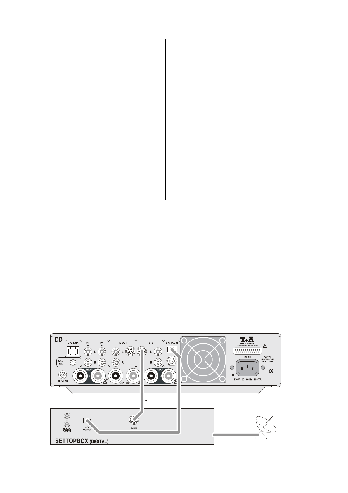
Digitaler SAT-Receiver
(Settopbox)
Führen Sie die Verkabelung der Komponenten gemäß
Anschluss-Schema 1 wie folgt durch:
• Falls die Settopbox über einen optischen Dolby Digital
Tonausgang verfügt, so schließen Sie diesen über
einen Lichtwellenleiter an den optischen Digitaleingang
(DIGITAL INPUT) des Decoders an.
Im 'Eingänge-Menü' ist dann unter STB IN der Eingang 'Dig. opt.' einzustellen.
Hinweis:
Falls die Settopbox über einen koaxialen Digitalausgang verfügt, so schließen Sie diesen über ein CoaxKabel an den koaxialen Digitaleingang
(DIGITAL INPUT) des Decoders an.
Im 'Eingänge-Menü' ist dann unter STB IN der Eingang 'Dig. koax' einzustellen.
• Mit einem S-Video-Kabel verbinden Sie die S-Video–
Buchse der Settopbox mit der Buchse STB des
Decoders.
• Falls die SETTOPBOX keinen S-Video-Ausgang hat,
muss ein Scart / S-Video Adapter verwendet werden.
Bitte wenden Sie sich an Ihren Fachhändler.
Anschluss-Schema 1
Eine Settopbox (digitale Ton- und Bildquelle) am DD 820 M.
26
Page 27

Analoger SAT-Receiver
• Wenn der Receiver einen S-Video-Ausgang hat,
schließen Sie ihn gemäß Anschlussbild 2 an.
• Wenn der Receiver über einen Scart / S-Video-Aus-
gang verfügt, schließen Sie ihn gemäß Anschlussbild 3
an.
Anschluss-Schema 2
Hinweis:
Anstelle eines analogen SAT-Receivers kann in gleicher
Weise auch jedes andere analoge Video-Quellgerät an
den STB-Eingang angeschlossen werden.
Analoger SAT-Receiver mit S-Video-Ausgang am DD 820 M.
Anschluss-Schema 3
Analoger SAT-Receiver mit Scart Ausgang am DD 820 M.
27
Page 28

Hinweise zur Optimierung
Lautsprecher- und Signalkabel
Die verwendeten Lautsprecher- und Signalkabel haben
einen nicht zu unterschätzenden Einfluss auf die
Wiedergabequalität der Gesamtanlage. empfiehlt
daher die Verwendung hochwertiger Kabel und Steckverbinder.
In unserem Zubehörprogramm finden Sie eine Reihe
exzellenter Kabel und Stecker, die in ihren Eigenschaften
auf unsere Lautsprecher und Elektronikkomponenten
abgestimmt sind und hervorragend mit diesen harmonieren.
Für schwierige und beengte Aufstellungsbedingungen
finden Sie im Zubehör auch Kabel in Sonderlängen
und Sonderstecker (z. B. in abgewinkelter Form), mit
deren Hilfe sich fast jedes Anschluss- und Aufstellungsproblem lösen lässt.
Netzkabel und Netzfilter
Über die Netzstromversorgung gelangt nicht nur die
notwendige Betriebsenergie zu Ihren Geräten, sondern
oft auch Störungen von entfernten Geräten, Funk- und
Computeranlagen.
Um elektromagnetische Störungen von den Geräten fern
zu halten, bietet unser Zubehörprogramm das spezielle
abgeschirmte Netzkabel 'POWER FOUR', das konfektionierte Netzkabel mit Mantelkernfiltern 'POWER LINE'
und die Netzfilterleiste 'POWER BAR'.
Mit diesem Zubehör kann die Wiedergabequalität
unserer Geräte in vielen Fällen nochmals gesteigert
werden.
Zu allen Fragen rund um die Verkabelung berät Sie gern
Ihr Fachhändler kompetent, umfassend und unverbindlich. Gern senden wir Ihnen auch unser umfangreiches Informationsmaterial zu diesem Thema.
28
Page 29

Betriebsstörungen
Viele Betriebsstörungen haben eine einfache Ursache,
die sich leicht beheben lässt. Im folgenden Abschnitt
sind einige mögliche Störungen sowie Maßnahmen zu
deren Behebung aufgeführt.
Sollte sich eine aufgetretene Störung durch diese Hinweise nicht beheben lassen, so ziehen Sie bitte umgehend den Netzstecker und wenden sich an eine autorisierte -Fachwerkstatt.
Störung: Lautes Brummen aus den Lautspre-
chern.
Ursache:
Abhilfe:
Störung: Kein Ton oder verzerrter Ton.
Ursache:
Abhilfe:
Schlechter Kontakt der Cinch-Stecker
oder ein defektes Cinchkabel.
Überprüfen Sie bitte genau alle Steckverbindungen und Verbindungskabel.
Audio-Verbindung zum Verstärker bzw.
Fernsehgerät nicht korrekt.
Verbindungen gemäß AnschlussSchema herstellen; Stecker fest einstecken. Zum Überprüfen des Verstärkers eine andere Hörquelle wählen.
Ursache 4:
Abhilfe: Gegebenenfalls 'Haupt Menü' aufrufen
Ursache 5:
Abhilfe: 'LS Balance Menü' aufrufen und den
Störung: Kein Bass oder zu wenig Bass.
Ursache 1:
Abhilfe:
Ursache 2: Lautsprechergrößen im 'Lautsprecher
Abhilfe: 'Lautsprecher Menü' aufrufen und
Programm enthält auf den betreffenden
Kanälen keine Informationen (z. B.
Stereo-Programm).
und ein Klangfeld wählen.
Für den betroffenen Kanal ist der Pegel
zu gering eingestellt.
Pegel erhöhen.
Kein Subwoofer angeschlossen aber im
'Lautsprecher Menü' aktiviert.
Subwoofer anschließen oder Subwoofer
im 'Lautsprecher Menü' deaktivieren.
Menü' falsch angegeben.
Einstellungen entsprechend den vorhandenen Lautsprechern überprüfen
und ggf. korrigieren.
Störung: Kein Ton oder zu leise Tonsignale
aus der Mittelposition.
Ursache:
Abhilfe:
Störung: Kein Ton aus einzelnem Laut-
Ursache 1: Lautsprecher im 'Lautsprecher Menü'
Abhilfe: 'Lautsprecher Menü' aufrufen und den
Ursache 2:
Abhilfe:
Ursache 3:
Abhilfe: 'Haupt Menü' aufrufen und auf
Kein Centerlautsprecher angeschlossen
aber im 'Lautsprecher Menü' aktiviert.
Centerlautsprecher anschließen oder
Centerlautsprecher im 'Lautsprecher
Menü' deaktivieren.
sprecher.
nicht aktiviert.
angeschlossenen Lautsprechertyp eintragen.
Lautsprecherkabel nicht richtig angeschlossen oder Kurzschluss im Lautsprecherkabel.
Anschluss und Lautsprecherkabel überprüfen und ggf. korrigieren.
Decoder ist nicht auf Surround-Betrieb
geschaltet.
'SURROUND' oder ein Klangfeld
schalten.
Störung: 'Haupt Menü' nicht auf den Bild-
schirm sichtbar.
Ursache: Bildschirmdarstellung des 'Haupt
Menüs' im 'Konfigurations Menü'
abgeschaltet
Abhilfe: 'Konfigurations Menü' aufrufen und
'Bildschirm Menü' einschalten.
Störung: Weder Bildschirm Menü noch
sonstige externe Programme werden
vom Fernsehgerät wiedergegeben. Es
erscheinen nur die TV-Programme,
die über die eigene Antenne empfangen werden.
Ursache:
Abhilfe:
Videokabel nicht richtig eingesteckt.
Alle Kabel fest einstecken!
29
Page 30

Störung: Bild "läuft durch".
Ursache:
Abhilfe:
Störung: Bild ist schwarz-weiß.
Ursache:
Abhilfe:
Hinweis:
Störung: Bei der Wiedergabe einer NTSC-DVD
Ursache:
Abhilfe:
Synchronisations-Signal fehlt.
Kabel fest einstecken oder Fernsehgerät korrekt auf Betriebsart 'AV-
Betrieb' einstellen.
Bildnorm des Fernsehgerätes, des
Decoders und des Quellgerätes
stimmen nicht überein.
Fernsehgerät, Decoder und Quellgerät
auf gleiche Bildnorm einstellen.
Bei Problemen stellen Sie am Decoder
die Norm 'RGB / Video' ein; für das
Fernsehgerät und das Quellgerät
wählen Sie die Bildnorm 'Video', gelegentlich auch als 'FBAS' oder
'Composite' bezeichnet.
erscheint das Bildschirm Menü verzerrt.
Das Fernsehgerät verfügt nicht über
eine automatische Formaterkennung für
NTSC und wurde manuell auf NTSC
eingestellt. Da die Bildschirm Menüs
des Decoders nur im PAL-Format erzeugt werden, ist dieser Betrieb nicht
möglich.
Verwenden Sie ein Fernsehgerät mit
automatischer Formatumschaltung
PAL / NTSC oder benutzen Sie das
Anlagendisplay.
Störung: Das Bild ist in Ordnung; es ist jedoch
kein Ton über den Decoder hörbar.
Ursache 1:
Abhilfe:
Ursache 2: Dem Bildeingang wurde im 'Eingänge
Abhilfe:
Ursache 3:
Abhilfe 1:
Abhilfe 2:
Störung: Beim Umschalten der Fernsehpro-
Ursache:
Abhilfe:
Störung: Decoder schaltet nach gewisser Be-
Ursache:
Abhilfe:
Keine Tonverbindung zwischen Quellgerät und Decoder.
Stellen Sie die Tonverbindung her (analog oder digital je nach Betriebsart), s.
Kapitel 'Installation, Inbetriebnahme,
Sicherheitshinweise'.
Menü' kein oder ein falscher Tonein-
gang zugeordnet.
Überprüfen Sie, an welchen Toneingang
das Quellgerät angeschlossen ist. Dann
'Eingänge Menü' aufrufen und die
korrekte Zuweisung vornehmen.
Der Lautsprecher ist abgeschaltet.
Lautsprecher mit dem
einschalten.
Überprüfen, ob der Decoder durch
Überhitzung oder einen Kurzschluss in
der Lautsprecherleitung abgeschaltet
hat.
gramme sind Störgeräusche hörbar.
Das Fernsehgerät ist nicht in der Lage,
die SCART-Audio-Ausgänge zu muten
(stumm zu schalten).
Verwenden Sie die Cinch-/Tonausgänge
des Fernsehgerätes (falls vorhanden)
anstelle des SCART-Tonausganges.
triebszeit ab.
Überhitzung.
Für ausreichende Kühlluftzufuhr sorgen;
ggf. Lautstärke verringern.
-Taster
30
Page 31

Das
Surround-System
Mehrkanalige Wiedergabe mit Hilfe von Surroundtechniken eröffnet zwar neue Erlebniswelten, die technische Realisierung eines Mehrkanal Surroundsystems
birgt aber auch einige Risiken. Viele Surroundsysteme
stehen im Ruf, nur eine relativ geringe Klangqualität,
insbesondere im normalen Stereobetrieb, zu erbringen.
Die Ursache hierfür liegt darin, dass analoge Stereosignale sehr empfindlich sind. Ihre Signalpegel liegen im
Bereich von nur wenigen Millivolt (Tausendstel Volt) und
bereits Störsignale, die nochmals tausendfach kleiner
sein können, vom menschlichen Ohr noch störend wahrgenommen werden. Die in normalen Surroundverstärkern betriebene Vereinigung von Digitalsignalen und
hochfrequenten Videosignalen zusammen mit empfindlichen Analogsignalen in einem gemeinsamen Gehäuse
öffnet der gegenseitigen Störübertragung Tür und Tor.
Dies wollten wir bei der Konzeption unseres
Surroundsystems keinesfalls akzeptieren und entwickelten daher ein System mit einer konsequent getrennten und auf zwei spezialisierte Geräte aufgeteilten
Signalverarbeitung: für hochwertige Stereosignale steht
ein analoger zweikanaliger Stereoverstärker zur Verfügung, die Verarbeitung der digitalen Surroundsignale
geschieht im eigenständigen Surround-Decoder.
Analoge und digitale Baugruppen sind beim System
bestens voneinander getrennt. Der Decoder ist im
Stereobetrieb vollständig abgeschaltet und aus dem
Signalweg verbannt. Eine Beeinflussung der empfindlichen Analogsignale wird auf diese Weise vermieden
und eine klangliche Beeinträchtigung bei analoger
Stereowiedergabe ist ausgeschlossen.
Damit das Gesamtsystem optimal harmoniert, sind die
im Decoder eingebauten Endstufen schaltungstechnisch
identisch zu unseren Stereoendstufen. Identisches
Frequenz-, Phasen- und Transientenverhalten aller
Kanäle sind auf diese Weise ebenso gewahrt wie absolut
gleiche dynamische Eigenschaften.
Das Surroundkonzept bietet weitere Vorteile. Es
stehen zwei getrennte Vorverstärkerzweige mit jeweils
eigenen Lautstärke- und Klangregelfunktionen zur Verfügung: Ein Stereovorverstärker und ein davon unabhängiger Sechskanalvorverstärker im Surround-Decoder.
Es ist daher möglich, für Stereo und Surround jeweils
unterschiedliche, den Erfordernissen angepasste Pegelund Klangeinstellungen vorzunehmen. Mit dem Wechsel
der Betriebsart werden so auch gleich die richtigen Einstellungen aktiv.
31
Page 32

Glossar
AV-Quellgerät
Ein Quellgerät, das Ton- und Bildsignale liefert. Die Tonsignale können in analoger oder digitaler Form ausgegeben werden.
Center
Vorderer Mittellautsprecher, der unter oder direkt neben
dem Fernsehgerät angeordnet ist.
dB
Die Maßeinheit für elektrische Pegel ist das dezi Bel (dB).
DSP (Digitaler Signal Prozessor)
Im digitalen Surround Decoder wird ein frei programmierbarer Signalprozessor eingesetzt. Ein DSP kann
digitale Signale nach einem im Programmspeicher abgelegten Programm bearbeiten. Das Programm kann
jederzeit ausgetauscht werden (Update). Dadurch kann
der Decoder neuen Erfordernissen angepasst werden.
Front-Speaker
Vorderes Hauptlautsprecherpaar links und rechts neben
dem Fernsehgerät.
M
LINK
Über diese Steuerschnittstelle kommunizieren alle Komponenten einer M-Anlage miteinander. Quellgeräte
werden über diese Schnittstelle auch mit Spannung
versorgt.
Surround
Allgemeines:
Bei einer normalen Stereoaufzeichnung stehen bekanntlich zwei Kanäle - links und rechts - zur Verfügung. Bei
einer Stereoreproduktion in Ihrem Hörraum findet das
gesamte Klanggeschehen auf einer imaginären Bühne
statt, die sich zwischen den Lautsprechern erstreckt. Der
Hörer kann Schallereignisse sehr gut in der Breite der
Bühne und bei guten Aufnahmen auch in einem
geringeren Maße in der Tiefe hinter den Lautsprechern
orten. Trotzdem bleibt der Hörer bei stereophonen
Wiedergaben immer isoliert vor dem Geschehen.
Eine packende Live-Atmosphäre wie im richtigen
Konzertsaal kann nicht korrekt reproduziert werden, da
die Akustik des Konzertsaales maßgeblich von Schallreflexionen der Seiten- und Rückwände, des Bodens, der
Raumdecke und von Gegenständen im Saal beeinflusst
wird. Die Reflexionsanteile kommen aus unterschiedlichen Richtungen, nicht nur von vorn.
Eine wirklichkeitsgetreue Abbildung muss daher Schallanteile aus allen Raumrichtungen in korrekter zeitlicher
Staffelung und mit korrektem Pegel wiedergeben.
Die Wiedergabe des Fernsehtons über eine herkömmliche Stereoanlage ist problematisch, weil eine Lokalisierung von Sprechern auf dem Bildschirm oft nicht möglich
ist.
Ebenso konnten Klangeffekte aus dem Kino, die dort seit
den 50er Jahren schon über mehrkanalige Tonanlagen
erreicht wurden, und die oftmals einen Film zum Erlebnis
werden lassen, zu Hause nicht reproduziert werden.
In den letzten Jahren wurden Surroundtechniken entwickelt, die alle diese Effekte auch in den eigenen vier
Wänden erlebbar machen und die eine größere Realitätsnähe als herkömmliches Stereo schaffen können.
Für eine gute Surroundanlage ist ein Centerlautsprecher,
der unter oder direkt oberhalb des Fernsehgerätes installiert wird, unbedingt zu empfehlen. Dieser Lautsprecher
erleichtert die Lokalisierung von Schallereignissen (z. B.
Dialogen) auf dem Bildschirm ganz erheblich.
Rear-Speaker
Hinter dem Hörplatz aufgestelltes Lautsprecherpaar für
Raumklangeffekte.
SCART
Weitverbreitete Anschlussnorm mit 21-poligem Normstecker. Durch SCART-Verbindungen können alle Bildnormen und zusätzliche Steuersignale (z. B. für 4:3/16:9
Bildformat-Umschaltung) übertragen werden. Für den
Übergang von SCART auf andere Steckernormen (Cinch
oder Hosiden) stehen im Fachhandel Adapter zur Verfügung.
Subwoofer
Lautsprecher für Tieftonwiedergabe. Er wird eingesetzt
für spezielle Tieftoneffekte, die bei Dolby Digital- und dtsProgrammen auf den LFE-Kanal codiert sind. Bei
Lautsprecher-Kombinationen mit kleinen Satelliten-Lautsprechern ermöglichen sie auch eine volle Basswiedergabe.
Dolby ProLogic II Surround
Bei diesem Verfahren werden mehrere unabhängige
Signalkanäle mittels eines speziellen Codierverfahrens
auf einem zweikanaligen Tonträger aufgezeichnet. Da
dieses Verfahren nur zwei Aufzeichnungskanäle benötigt, ist es mit vielen verbreiteten Bild-/Tonsystemen
kompatibel (CD, Videorecorder, TV etc.).
Die Informationen werden bei der Wiedergabe decodiert
und über vier (links, rechts und 2x hinten), besser jedoch
über fünf Lautsprecher (mit einem zusätzlichen Centerlautsprecher vorn), im Hörraum wiedergegeben. Dolby
Surround codiertes Programm-Material findet man derzeit hauptsächlich im Film- und Videobereich auf Videocassetten und DVDs, jedoch werden derzeit auch schon
eine große Anzahl von Fernsehproduktionen in Dolby
Surround produziert und ausgestrahlt.
32
Page 33

Dolby Digital
Dolby Digital ist ein digitales Mehrkanal-Surroundsystem,
das für die räumliche Tonwiedergabe von Kino-Filmen
entwickelt wurde. Das Verfahren benutzt fünf separate
Tonkanäle: drei Frontkanäle (links, Mitte, rechts) und
zwei Surroundkanäle. Darüber hinaus ist ein sechster
unabhängiger Basseffekt-Kanal für Tieffrequenzeffekte
(LFE) vorhanden. Deshalb spricht man von 5.1 Kanälen.
Gegenüber Dolby Surround sorgen die beiden unabhängigen Surround-Kanäle für echten Stereo-Raumklang
bzw. aufgeteilten Raumklang mit der gleichen wirklichkeitsgetreuen Stereo-Wiedergabe wie bei den Frontkanälen.
Der integrierte Dolby Digital Decoder ermöglicht die
Realisierung einer digitalen Dolby Stereo-Kinovorstellung
im eigenen Wohnzimmer. Das diskrete digitale Aufnahmeverfahren sowie die fünf Wiedergabekanäle
garantieren eine sehr große Dynamik und eine präzise
Raumorientierung.
S-VIDEO
Hochwertige Bildnorm mit getrennter Helligkeits- und
Farbübertragung. Bessere Bildqualität als StandardVideo.
Update
Austausch des Programms vom Bedien- oder Signalprozessor des Gerätes. Dadurch werden Funktionserweiterungen und Anpassungen an neue Erfordernisse
möglich.
VIDEO
Standard-Bildnorm; Farb- und Helligkeitsinformationen
werden gemeinsam übertragen. Standard-Video-Anschlüsse sind an allen AV-Geräten vorhanden.
dts Digital Surround
Das Mehrkanal-Filmtonsystem "dts" wurde ursprünglich
entwickelt, um die analogen Film-Tonspuren durch
digitale Tonspuren mit sechs diskreten Kanälen zu ersetzen. Dieses System wurde für die Raumklangwiedergabe im Heimbereich weiterentwickelt.
Die sechs Kanäle (5.1) werden in Originalqualität, d. h.
mit einer Auflösung von 20 Bit codiert / decodiert und mit
einer relativ geringen Datenkompression aufgezeichnet.
Zur Wiedergabe eignet sich die 5.1 Lautsprecherkonfiguration, die derzeit für Heimkinosysteme üblich ist.
Klangfeldsimulation
Neben den oben beschriebenen Surround Verfahren, für
das entsprechend codiertes Programm-Material benötigt
wird, bietet der digitale Surround Decoder auch eine
Möglichkeit, die räumlichen Effekte bei herkömmlichen,
uncodierten Stereoaufzeichnungen (CD, MC, UKWRundfunk etc.) zu steigern.
Dazu stehen eine Reihe von Klangfeldsimulationen zur
Verfügung wie z. B. Opera, Arena, Club usw.
Diese Klangfelder basieren auf der genauen Analyse der
Raumakustik entsprechender Konzertsäle.
Der digitale Signalprozessor Ihres Decoders ist in der
Lage, den Raumklang dieser Säle nachzubilden und
über die fünf Kanäle des Systems wiederzugeben.
Wenn Sie nun z. B. bei der Übertragung eines Rockkonzertes im Fernsehen die Einstellung HALLE wählen,
so erhalten Sie die Illusion, mitten zwischen den Zuschauern zu sitzen.
In diesem Zusammenhang sei darauf hingewiesen, dass
das Klangfeld dem gerade gehörten Programm angepasst sein sollte. Es macht sicherlich keinen Sinn, ein
Kammerkonzert in eine Arena oder ein Rockkonzert in
einen Club zu verlegen.
Im digitalen Surround Decoder stehen Ihnen folgende
Klangfelder zur Verfügung:
HALLE, OPERA, ARENA, CLUB, KIRCHE, DISCO
33
Page 34

34
Page 35

English
35
Page 36

Welcome.
We are delighted that you have decided to purchase a product. With the addition of the digital surround decoder to
your Hi-Fi system you are expanding it to embrace a completely new dimension: Audio-Vision.
With the digital surround decoder you can play Dolby Surround, Dolby Digital
programmes, video films and DVDs and experience a genuine “live” atmosphere, complete with exciting sound effects.
The digital surround decoder is also capable of generating artificial sound fields, which enhance the apparent reality of
non-encoded programme material. For example, if you are watching a sports programme, you can allow yourself to be
transported into the stadium, or listen to a jazz concert in an authentic simulation of the atmosphere of a typical jazz
club.
Of course, it is essential that all these new facilities should have no detrimental effect on the excellent sound qualities of
your Hi-Fi system, and the design of your new machine has been carefully thought-through from start to finish to ensure
that this is the case.
As you would expect, the digital surround decoder features three high-quality output stages of discrete construction,
offering outstanding sound characteristics and generous reserves of power, and they can cope with impedance-critical
loudspeakers and complex surround effects covering a very wide dynamic range without turning a hair. The unit
includes a high-precision digital signal processor which is responsible for precise decoding of the surround material as
well as generating the sound fields.
Naturally, we have remained faithful to our basic design and manufacturing principles in developing the digital surround
decoder. This design philosophy includes an insistence on durability and reliability, the avoidance of materials which are
environmentally harmful, the use of metals instead of plastics, and the exclusive exploitation of high-quality, thoroughly
tested materials. To ensure consistently high product quality we subject everything we make to a comprehensive
monitoring process, terminating in a fully automatic computer-controlled final quality check and acceptance procedure.
Optional accessories for this unit include high-quality cables and connectors, together with a range of specialised
furniture designed to match the design of our equipment.
1)
and dts
2)
encoded television
We are grateful to you for placing your faith in us, and hope that you will enjoy many hours of pleasure with your
digital surround decoder.
1) Manufactured under licence from Dolby Laboratories. “Dolby”, “Pro Logic“, and the double-D symbol are
2) “dts” is a trademark of Digital Theater Systems, Inc.
elektroakustik GmbH & Co KG
trademarks of Dolby Laboratories.
All components used in this device meet the current German and European safety norms and standards. For
your own safety please be sure to read right through these operating instructions. It is especially important to
observe the instructions regarding setting up and operating the equipment, and the safety notes.
36
Page 37

Contents
Operation
Front of the DD 820 M ............................................................................................................................................ 38
Stereo and Surround modes .................................................................................................................................. 38
Remote control ....................................................................................................................................................... 39
Menu control system .............................................................................................................................................. 40
• Main menu ........................................................................................................................................................ 41
Configuration, Installation, Using the unit for the first time, Safety notes
System configuration .............................................................................................................................................. 44
• Device Setup .................................................................................................................................................... 45
• Assistant Menu ................................................................................................................................................. 46
• Speaker Setup .................................................................................................................................................. 47
- Loudspeaker position menu ........................................................................................................................ 49
- Loudspeaker balance menu ........................................................................................................................ 50
- Tone control menu ...................................................................................................................................... 51
• Video Setup ...................................................................................................................................................... 52
• Source Setup .................................................................................................................................................... 53
Back panel connections ......................................................................................................................................... 54
Safety notes ........................................................................................................................................................... 55
FCC Information to the user ................................................................................................................................... 56
Connecting the TV set and surround speakers to the decoder .............................................................................. 57
Connecting a digital SAT receiver (set-top box) ..................................................................................................... 58
Connecting an analogue SAT receiver ................................................................................................................... 59
Optimising the system ............................................................................................................................................ 60
Miscellaneous
Trouble-shooting .................................................................................................................................................... 61
The surround system ..................................................................................................................................... 63
Glossary ................................................................................................................................................................. 64
Appendix
Wiring diagram ....................................................................................................................................................... 68
Specification ........................................................................................................................................................... 69
37
Page 38

Front of the DD 820 M
Introduction
The DD 820 M surround decoder expands the stereo
version of the M 820 system to form a high-quality
5.1 channel home cinema system. It adds two picture
and sound inputs to the M-system for the DVD 820 M
DVD player and a satellite or cable receiver (set-top
box).
The DD 820 M integrates completely into the M 820’s
operating system, and is controlled entirely by the F6
system remote control handset.
Information on the operating mode of the DD 820 M is
displayed on the central system screen of the PT 820 M.
The DD 820 M also features an on-screen menu which
displays operational and set-up functions in a clear form
on the screen of a TV set connected to the system.
Note:
These instructions only cover the DD 820 M surround
decoder. For information on installing and setting up the
full system and using it for the first time please read the
operating instructions supplied with the other system
components.
Operation
Switching On/Off
The DD 820 M is automatically switched on and off
together with the other components of the M-system.
Stereo and Surround modes
The M-system features a high-quality audiophile
stereo amplifier in the PT 820 M and PA 820 M, which is
complemented by the DD 820 M decoder to form a 5.1
channel surround and home cinema system.
In analogue stereo mode the PT 820 M is responsible for
all control and adjustment functions; the DD 820 M is
removed entirely from the signal path.
In surround mode the DD 820 M assumes the function of
the central control unit. The advantage of this design
philosophy is that it offers no interference to pure
analogue stereo reproduction, with a resultant gain in
potential musicality. Such quality is extremely difficult to
obtain with conventional surround arrangements.
Please read the section 'The
for more details and background information on this
subject.
Surround System'
Note:
As already mentioned, in analogue stereo mode the
DD 820 M surround decoder is switched out of circuit in
order to achieve highest possible sound quality. For this
reason the 'on-screen menus' of the DD 820 M, as
described in these instructions, are not available in this
mode.
Setups in stereo-mode occur, like M-System without
DD 820 M, via the integral display screen of the
PT 820 M.
38
Page 39

Remote control of the Surround Decoder
General information
The F6 system remote control handset provides directaccess buttons for the essential basic functions of the
decoder, such as selecting the sound and picture source
and adjusting the volume.
In the drawings some of the buttons are filled in
(
); these are the ones which are required for
remote control of the decoder. The other buttons have no
effect on this unit.
Selects the DVD 820 M as source.
Selects the tuner as source.
Selects the AUX/PH input as source.
Selects one of the inputs TV or STB
(satellite receiver) as source. Pressing this
button repeatedly switches between TV and
STB.
Selects one of the inputs TAPE 1 (CC 820 M)
or TAPE 2 as source. Pressing this button
repeatedly switches between TAPE 1 and
TAPE 2.
Volume control rocker.
Press briefly to select the loudspeaker
outputs in turn:
A B A/B
Holding the button pressed in switches off
the loudspeaker outputs.
Switches between surround mode and
stereo mode.
Supplementary functions
Decoder functions which are only required occasionally,
i. e. which do not need to be changed every day (e. g.
tone controls or surround mode) are controlled by
accessing an on-screen menu ('Main Menu'). The
individual functions of the main menu are described in
detail in the following section.
Basic settings
The decoder’s basic settings and configuration, which
only have to be entered when the system is first
commissioned, or if you make a fundamental change to
the system, are accessible via the Configuration Menu.
The procedures are explained in greater detail in the
'System Configuration' section.
39
Page 40

Menu control system
The DD 820 M features a 'Main Menu' which enables
you to control rarely needed supplementary functions,
and a 'Configuration Menu' which enables you to carry
out the basic set-up and configuration processes for the
device.
In most cases the 'Configuration Menu' is only required
the first time the system is used, although it is also
needed if you make a fundamental change to the
system.
All the menus are displayed page by page on the screen
of the TV set connected to the system. The individual
menu point you select is also displayed on the
PT 820 M’s integral screen. This ensures that you can
also operate the menus without the TV set being
switched on.
The menu system is operated by using the remote
control buttons
.
, , , , ,
Brief press:
opens and closes the Main Menu.
Hold pressed in for about 3 seconds:
opens the Configuration Menu.
Selects a menu point.
and
Changes the setting of the currently
selected menu point.
Activates the currently selected function.
Closes the menu.
Note:
If you are using the F1 system remote
control handset note that the
rocker can also be used instead of the
button.
40
Page 41

Main Menu
Press the
Menu', which then appears on the screen. Select a menu
point using the / buttons, and change the setting
using the / buttons.
button briefly to open the 'Main
Listening mode:
At this menu point you can select the decoder’s playback
mode or sound field which you wish to use. The decoder
'remembers' your chosen setting for each input, and
selects it every time you switch to that input.
Surround The decoder detects an encoded digital
multi-channel signal, decodes it and passes it to all the
output channels. The current mode of operation of the
decoder is displayed on the integral system screen. If the
signal is analogue, the decoder always uses Dolby Pro
Logic decoding.
Stereo Even if a multi-channel signal is detected, the
decoder converts it into a stereo signal, i. e. all channel
information is mixed down and sent to the main left and
right loudspeakers.
Mono All channels are mixed down onto the center
loudspeaker channel.
Mono I Mode for two-channel TV sound
Generally Channel I transmits the synchronised sound.
The signal from Channel I is reproduced via the Centre
loudspeaker *); Channel II (original sound) is
suppressed.
Mono II Mode for two-channel TV sound
Generally Channel II transmits the original sound. The
signal from Channel II is reproduced via the Centre
loudspeaker *); Channel I (original sound) is
suppressed.
Note:
*) If no Centre speaker is present (see 'Loudspeaker
Menu'), the Centre channel is mixed onto the left and
right main speakers.
Not all signal sources (DVDs, CDs etc.), which are Dolby
Digital or dts Digital Surround encoded contain full 5.1
information. Even if the screen indicates that a particular
channel is present, this does not necessarily mean that
the loudspeaker in question will always produce sound.
In every playback mode signals may be present on the
subwoofer channel; this depends on the loudspeaker
arrangement you have selected in the 'Speaker Setup'.
The menu can be closed again at any time by pressing
the
or
handset, or by holding the
machine’s front panel pressed in.
button on the remote control
button on the
Sound fields:
Disco This sound field is particularly suitable for
providing an even spread of sound over a dance floor,
using the front and surround loudspeakers. The sound
signal is mixed and passed to the front and surround
speakers without reflections and delays, and with equal
power. The strongly concentrated sound reproduction
generates an immediate, energy-charged atmosphere
which is a great choice for any party.
Hall Reverberant concert hall with sound reflections
from all directions. Ideal for playing back recordings of
large orchestras, or simulating the live atmosphere of a
large rock concert hall - an excellent choice for very
dynamic rock music.
Opera This program combines clear voice reproduction
with the full sound of an orchestra, but without
exaggerated reverberation. The spatial sound towards
the rear is slightly limited, in the interests of better
orientation.
Arena This sound image concentrates the “presence”
in the front area, helping to localise commentators and
dialogues on the screen. Sound from the rear is
designed to give the impression of being amongst the
spectators in the stadium. This sound field is also
suitable for TV shows and music programmes.
Club The characteristic atmosphere of a cellar jazz
club, with a pattern of reflections dominated by large
floor and wall surfaces. Also good for simulating small
halls.
Church Simulation of the acoustic conditions in a large
church, with long reverberation times. This sound field is
an excellent choice for sacred organ music.
41
Page 42
ProLogic II mode:
Subwoofer level:
This menu point enables you to set the Dolby ProLogic II
decoder to suit varying programme material.
Movie for films
Music for music
Matrix for mono programme material
Balance left/right and front/surround:
These two menu points allow you to set a temporary
change in the balance between the left/right and
front/rear loudspeakers, in order to compensate for a
temporary listening position which is less than perfect.
You can alter the balance in 1 dB increments, and the
current value is displayed in the following form:
10L (left) . . . . . . . . 10R (right)
10R (surround) . . . 10F (front)
Center (neutral position)
Note:
It is important to start by setting the correct balance for
the “standard” listening position, adjusting the volume of
the front, surround and center channels. This task is
carried out in the 'Speaker Balance Setup'.
If you switch on the subwoofer in the 'Speaker Setup', in
this menu point you can adjust its level within the range 10 (dB) to +10 (dB) in order to match its volume to the
acoustic conditions in your listening room, and to match
the volume of the other channels.
If the subwoofer is switched off in the 'Speaker Setup',
this menu point in the 'Main Menu' shows off . You
cannot adjust the subwoofer level in this situation.
Note:
It is important to start by setting the correct balance
between the other channels (front, rear and center). This
task is carried out in the 'Speaker Balance Setup'.
Sub-woofer volume:
The first step in setting the volume of the sub-woofer is to
adjust the value for the sub-woofer in '
until the level is correct. The second step is to carry out
the loudspeaker calibration process in '
after which the sub-woofer level can be fine-tuned in the
main menu. Please keep to this sequence, as it is the
only way to ensure that you obtain optimum sound both
in '
PT
PT STEREO
STEREO
PTPT
STEREO STEREO
Please read the section 'Stereo and Surround Modes'
for more information on '
modes.
' mode and in '
SURROUND
SURROUND
SURROUNDSURROUND
PT
PT STEREO
STEREO
PTPT
STEREO STEREO
PT
PT STEREO
STEREO
PTPT
STEREO STEREO
SURROUND
SURROUND
SURROUNDSURROUND
'.
' and '
' mode
' mode,
SURROUND
SURROUND
SURROUNDSURROUND
'
Tone: treble and Tone: bass:
These two menu points allow you to set a temporary
change in the treble and bass settings in order to
compensate for tonal differences in the recorded
material. The setting affects all channels, and the range
of adjustment is +/- 6 dB in 1 dB increments. The current
value is displayed on the screen; 00 dB means 'Linear
setting'.
Note:
It is important to start by establishing the correct tone
settings for your room, to allow for imperfect loudspeaker
positioning or room influences. This task is carried out in
the 'Tone Control Menu'.
Loudness:
Toggles volume-dependent tone correction
(LOUDNESS) on and off. The display area of the
decoder always shows the current status briefly in text
form; the symbol in the display window is the
permanent indicator that loudness is switched on.
Dynamic range:
The dynamic range is the difference in volume between
the quietest and loudest passages of a recording. The
original sound track of a film usually features a very wide
dynamic range, and the decoder is capable of
reproducing the full range.
Unfortunately not every listening room can cope with the
full dynamic range which the decoder is capable of
reproducing. You also have to consider your neighbours,
especially in the late evening.
To cope with these problems it is possible to reduce the
dynamic range of Dolby Digital encoded sound material
in three stages. The result is that quiet passages (e. g.
low-level conversations) are reproduced slightly louder
when the volume is set low, whereas loud passages
(e. g. gigantic explosions) are slightly reduced in volume.
The following dynamic ranges are available:
standard highly compressed dynamic range, e. g.
for playing at night-time.
high standard setting, moderate compression of
dynamic range.
full exploits the full dynamic range which the
sound source makes available.
Note:
Any adjustment to the dynamic range only affects Dolby
Digital encoded sound sources.
42
Page 43

Installation
Using the unit for the first time
Safety notes
This chapter describes all the matters of fundamental importance for setting up and operating your DVD player. This
information is not relevant to your daily handling of the system, but should still be read and noted carefully before using
the machine for the first time.
43
Page 44

System Configuration
In the 'Device Setup' you can adjust the settings for all
the audio and video components of your surround
system so that they match each other perfectly, and at
the same time set them to suit the acoustic
characteristics of your listening room.
Summary of 'Device setup
'
This procedure only needs to be carried out when you
are installing the system, or when you are adding or
replacing individual components of the system. The
following diagram shows the menu structure.
All menus are displayed page by page on the screen of a
television set (if connected), and at the same time line by
line on the decoder’s integral screen.
The following section describes the menu points and
explains the adjustment facilities and their effects.
44
Page 45

Device Setup
The system is controlled entirely using the F6 remote
control handset. Hold the AMP button pressed in for
about 3 seconds to open the 'Configuration Menu'. Use
the / buttons to select a menu point, and change
the value with the / buttons.
Switching the on-screen main menu on
and off:
If you just wish to make a temporary change to the
balance or tone, it is not absolutely necessary to call up
the 'Main Menu' on the television screen and
superimpose it on what you are watching; in most cases
the display on the decoder’s screen is quite adequate. At
this menu point you can switch the TV on-screen main
menu display on and off.
The menu can be closed again at any time by pressing
the
or
button.
Picture norm:
In this menu you set the picture norm for the TV output.
Source:
The 'Inputs Menu' is used to assign the digital input for
the source STB.
off The 'Main Menu' appears line by line on the
decoder’s screen, but not on the TV screen.
on The 'Main Menu' appears on the TV screen
and also line by line on the decoder’s
screen.
On-screen language:
The on-screen menus can be displayed on the screen in
a variety of languages. The on-screen menus then
appear in the language you select.
Setup-Assistant:
The 'Setup assistant' menu point represents an
alternative to the manual 'Loudspeaker Menu'. Calling
up the Assistant invokes an automated routine for
correctly setting up the individual loudspeaker channels
of your surround system.
Loudspeaker:
The 'Speaker Setup' provides the means to balance the
output signals to the loudspeakers in your surround
system. At the same time you can adjust the output of
the speakers accurately to suit the acoustic and spatial
characteristics of your listening room.
45
Page 46

Assistant Menu
The purpose of the Setup Assistant is to help you
set up your surround system correctly. If you follow the
steps described below, the DD 820 M will automatically
calibrate your loudspeakers with the help of the
measurement microphone supplied, and under normal
listening room conditions this procedure will deliver
optimum results from your system.
If the automatic calibration system is to work properly the
following conditions must be satisfied: the measurement
microphone must be set up with free space all round it,
close to your preferred listening position (e. g. on the
living room table, or on the arm of an armchair). There
must be straight-line visual contact between the
microphone and each loudspeaker.
The unit is supplied with a calibration microphone.
Connect this to the socket marked CAL MIC. on the back
panel of the DD 820 M. Set the system to a normal
listening volume.
Call up the Setup Assistant and the menu shown below
appears.
Main speaker:
Center speaker:
Rear speaker:
Subwoofer:
The first step is to enter the size of your loudspeakers in
the right-hand column of the menu (see 'Loudspeaker
Menu'), and state whether your system includes a
subwoofer or not.
Auto-setup:
Now move to the 'Auto-setup' menu point and press the
button to activate the menu point.
To ensure that the calibration process can be carried out
correctly it is essential to set the volume to the optimum
level beforehand. To help set the correct level the
DD 820 M generates a hissing signal on the front left
channel. In the 'Volume' line on the screen you will see
the currently set volume, following by a flashing indicator
informing you which button to press. 'VOL+' means that
the volume is too low. 'VOL-' means that it is too high.
The calibration process is initiated by pressing the
button, but this will not work until you see 'OK' on
the screen.
The DD 820 M will now carry out the automatic
calibration process. During this period you will hear
various test signals from your loudspeakers. The results
could be falsified if any loud noises occur during the
duration of the calibration process, so take care to keep
the room quiet.
The on-screen 'Auto-setup' display on your TV set
keeps you constantly informed about the settings it has
established. In the Level
column you will see the set
corrections (volume compensation), while the Dist.
column lists the measured loudspeaker distances.
Typical display of measured values
produced by the Auto-setup menu
Notes:
If the calibration process was spoiled by extraneous
sounds, or if implausible results are generated for
whatever reason, you can re-start the calibration process
at any time.
The distances established by the Assistant are
calculated on the basis of acoustic reflection times. They
may vary slightly from the true geometric distances due
to signal delays in your loudspeakers.
If the automatic calibration process supplies invalid
results due to difficult acoustic conditions in your
listening room, we recommend that you should first try
varying the microphone position and / or the volume
setting in an attempt to obtain a valid result.
If this does not bring about an improvement, making
automatic calibration impossible, you can still carry out
the loudspeaker set-up procedure manually via the
'Loudspeaker Menu'.
46
Page 47

Speaker Setup
The first purpose of the 'Speaker Setup' is to allow you
to distribute the output signals correctly to the
loudspeakers which form part of your surround system.
If your system does not include a “full set” of
supplementary loudspeakers (center, rear and
subwoofer), it is important to mark the missing items as
none in the 'Speaker Setup'.
The corresponding sound signal is then mixed down onto
those channels which are present (Downmix).
Main size:
The last three menu points enable you to adjust the
loudspeakers to suit the acoustic and spatial
characteristics of your listening room.
Adjustments should only be made to these settings when
you are installing the system, if you are adding, replacing
or moving individual loudspeakers, or if the acoustic
conditions in your listening room are changed (e. g.
changes to the furniture, carpets, curtains etc.).
Center size:
Defines the size and bass capacity of the main left and
right front loudspeakers. Select one of the following
settings: *)
satellite for small speakers whose bass
reproduction is necessarily restricted. The
low bass content (below 80 Hz) of the
main channel signals is mixed down onto
the subwoofer, if present.
full range for larger speakers. The full frequency
range is passed on to the main speaker
channels without restriction.
Defines the size and bass capacity of the center
speaker. Select one of the following settings: *)
none if no center loudspeaker is present. The
center channel is mixed down onto the left
and right main loudspeakers.
satellite for small speakers whose bass
reproduction is necessarily restricted. The
low bass content (below 80 Hz) of the
main channel signals is mixed down onto
the subwoofer, if present.
full range for a center speaker of about the same
size as the main loudspeakers. The full
frequency range is passed on to the center
channel without restriction.
Note:
If your system does not include a center speaker, the
main loudspeakers should be set up not too far away
from the TV set, and ideally should be arranged
symmetrically about it, otherwise it will be very difficult to
localise dialogues on the television screen.
47
Page 48

Rear Size:
Subwoofer:
Defines the size and bass capacity of the rear surround
loudspeakers. Select one of the following settings: *)
none if no surround loudspeakers are present. The
surround channels are mixed down onto the
left and right main loudspeakers.
Note:
Genuine surround reproduction is not possible without
rear speakers!
satellite for small speakers whose bass reproduction
is necessarily restricted. The low bass content
(below 80 Hz) of the main channel signals is
mixed down onto the subwoofer, if present.
full range for speakers which offer very good bass
reproduction. The full frequency range is
passed on to the surround channels without
restriction.
*) Note:
To avoid nonsensical settings, the system does not allow
you to set all the possible combinations (Front LS,
Center and Rear LS). The following list shows all the
standard combinations, but you can modify them
individually.
Standard combinations
1. Main, center and rear size: ....... Satellite
Subwoofer: ............................... on
In this menu point you set whether a subwoofer is
present in your loudspeaker system. Select one of the
following settings:
on If a subwoofer is present. The signals in the
Low Frequency effect channel (LFE), and all
other low-frequency bass signals (below
80 Hz) which are not within the compass of
the full-range loudspeakers, are passed to the
subwoofer channel.
off If no subwoofer is present. The signals from
the Low Frequency effect channel (LFE) and
all other low-frequency bass signals (below 80
Hz) are mixed down onto the main
loudspeakers.
Note:
Provided that you have switched on the subwoofer in
the 'Speaker Setup', then you can adjust its level in the
'Main Menu' within the range -10 (dB) to +10 (dB), so
that the volume of the subwoofer matches the volume of
the other channels.
Speaker position:
Activating this menu point leads to a further menu in
which you can define the position of the loudspeakers,
i. e. you can enter the distance from the listening position
to each loudspeaker separately. This enables the
decoder to compensate for timing discrepancies due to
differences in speaker location (see 'Speaker Position
Setup').
2. Main size: ................................. Full range
Center and rear size: ............... Satellite
Subwoofer: ............................... off
3. Main and rear size: ................... Full range
Center size: .............................. Full range
or ....... Satellite
Subwoofer: ............................... on
Noise sequencer:
Activating this menu point leads to a further menu in
which you can set the balance between the volume of all
the loudspeakers (see 'Speaker Balance Setup').
Tone adjust:
Activating this menu point leads to a further menu in
which you can adjust the tonal balance of the
loudspeakers (see 'Tone Control Menu').
48
Page 49

Speaker Position Setup
In the 'Speaker Position Setup' you can enter the
distance from the listening position (in 0.3 m increments)
for each loudspeaker separately.
This enables the decoder to compensate for timing
discrepancies due to differences in speaker location.
As the illustration shows, you use the select buttons to
move to the input positions in the following sequence.
Output channels not in use (see 'Speaker Setup')
cannot be edited.
• Main loudspeaker front left (FL)
• Center loudspeaker front center (Center)
• Main loudspeaker front right (FR)
• Surround loudspeaker rear right (SR)
• Surround loudspeaker rear left (SL)
• Active subwoofer (any position) (Sub)
Measure the distance between the listening position and
the loudspeakers in your surround system, and enter the
measured distances.
Use the change buttons to enter the measured distance
in increments of 0.3 m.
Note:
The maximum distance of a loudspeaker to the listening
position is 12 m. For acoustic reasons greater distances
cannot be recommended, and the system cannot
compensate for timing errors over a range greater than
12 m.
49
Page 50

Speaker Balance Setup
To ensure that the decoder supplies a balanced sound
image, the system allows you to adjust the volume of the
individual channels to provide a harmoniously balanced
arrangement.
When you activate the 'Speaker Balance Setup' you will
hear a hiss from the left main loudspeaker lasting two
seconds. You will find the data input position after the
first menu point.
'FL: 00 '.
As the illustration shows, the hiss is reproduced on all
the channels in turn, in each case lasting about two
seconds:
• Main loudspeaker front left (FL)
• Center loudspeaker front center (Center)
• Main loudspeaker front right (FR)
• Surround loudspeaker rear right (SR)
• Surround loudspeaker rear left (SL)
The system skips any output channels which are not in
use (see 'Speaker Setup').
When the hiss is sounding on a particular channel, the
on-screen menu indicates the corresponding input
position. You can now alter the value within the range –
10 to +10 using the change buttons. You can
immediately hear the result of any change you make.
If you alter the volume, the hiss continues on that
channel for a further two seconds before moving on to
the next channel. The input position then changes
accordingly.
The purpose of the 'Speaker Balance Setup' is to adjust
the level of all the channels.
You can override the automatic cycling process by
selecting a particular channel using the select buttons;
you can then adjust its level as you wish.
Take your time to set all the channels to give as even an
impression of volume as possible!
Note:
The hissing sound used for this is not suitable for
assessing bass volume; the volume of the subwoofer
channel can be adjusted in the menu point 'Subwoofer
level', which is part of the 'Main Menu'.
The levels you set for each channel are stored for use
when the surround system has been selected, and
applies to all surround modes.
50
Page 51

Tone Control Menu
The decoder features an active tone control system
(+/- 6 dB) whose purpose is to compensate for the
unwanted influence on playback quality of your listening
room, or of imperfect loudspeaker positions.
The first step is to select a sound source which you wish
to use as the basis for adjusting the tone controls. Make
sure that the sound source you choose is active on all
the channels, so that the sound image is typical of your
listening habits, and any changes you make to the tone
controls are immediately audible in that setting.
Once you have activated this section of the menu, you
will find the data input position after the first menu point.
'FL TB: 00 '.
You can now alter the value within the range –06 to
+06 using the change buttons; any change you make is
immediately audible.
Select the input position using the select buttons.
As the illustration shows, you can cycle through the input
positions in the following order:
Output channels not in use (see 'Speaker Setup')
cannot be edited.
The treble / bass balance can be adjusted separately for
all the output channels, and can therefore compensate
for problems caused by the location of individual
speakers.
• Main loudspeaker front left Treble (TB)
• Main loudspeaker front left Bass (BS)
• Center loudspeaker front center Treble (TB)
• Center loudspeaker front center Bass (BS)
• Main loudspeaker front right Treble (TB)
• Main loudspeaker front right Bass (BS)
• Surround loudspeaker rear right Treble (TB)
• Surround loudspeaker rear right Bass (BS)
• Surround loudspeaker rear left Treble (TB)
• Surround loudspeaker rear left Bass (BS)
Set values for treble (TB) and bass (BS) on all channels
which gives as well-balanced a sound image as possible.
Note:
Adjusting the tone controls has an influence on the
overall level of that channel. After making a change here
we recommend that you call up the 'Speaker Balance
Setup' again so that you can check the balance of all
channels and make corrections if necessary.
51
Page 52

Video Setup
Optimum picture quality is only possible if the picture
norms of all the video components in the system are set
up to match each other, and if the correct cables
(SCART, video-coax) for the selected picture norm are
used. In the ‘Video Setup’ you can set the picture norm
for all the decoder’s video inputs and outputs to match
the capabilities of the devices connected to it. Many AV
source devices can generate a picture signal using
different picture norms (Video, S-Video), and in this case
the picture norm you wish to use must often be set in a
menu on the AV source device. If you are not sure of
this, study the operating instructions supplied with the
source device and the TV set.
There is a large number of different picture norms on the
market, but not all of them are supported by all AV
source devices and TV sets. The decoder is designed to
handle the most widely used picture norms: Video and SVideo.
TV out:
S-Video For TV sets with S-Video sockets.
Video For TV sets with Video sockets.
52
Page 53

Source Setup
In this menu you can set the input which is to be used for
the SAT receiver (STB): either the analogue sound input
(L, R), or one of the digital inputs Digital IN optical or
Digital IN co-ax.
Calibration:
When external analogue sound sources are used,
optimum reproduction quality can only be obtained if the
DD 820 M’s analogue / digital converter is adjusted
accurately to match the output level of the source device.
The DD 820 M features an automatic calibration function
which sets this value. This is the procedure for setting
the correct level:
1. Select the desired analogue audio or AV source
device and play a fortissimo passage.
2. Call up the 'Inputs Menu', select Start Calibration
and press the
3. The message Running appears on the screen for
the duration of the calibration process.
button.
Notes:
Automatic calibration is available for all external
analogue audio and A/V source devices (TAPE 1,
TAPE 2, AUX/TV, AUX/PHONO, STB [if analogue]), and
the process should be carried out for all the devices
connected to these inputs.
The integral tuner is factory-set to the optimum level, and
it is therefore not possible to calibrate this source device.
If a source device occasionally overloads the system
(audible distortion) in very loud passages, even though
you have calibrated the converter for that source, the
integral screen will display the following message briefly:
'
O V E R L O A D
O V E R L O A D'.
O V E R L O A DO V E R L O A D
If this happens, the analogue/digital converter should be
re-calibrated to this source device.
The level adjustment process has no effect in '
mode.
PT STEREO
PT STEREO
PT STEREOPT STEREO
'
53
Page 54

Connections
SUBWOOFER OUTPUT
(Connections to the PA 820 M).
Loudspeaker terminals
REAR (R)
The rear right surround speaker is connected to these
terminals.
CENTER
The center loudspeaker, located at front center between
the main speakers, is connected to these terminals.
(CINCH)
Mains input
The mains power lead is connected to this socket. Be sure
to read and observe the sections entitled 'Installation,
Using the unit for the first time, Safety notes' before
you connect the decoder to the mains supply.
M
LINK
Control interface for connection to the amplifier
PA 820 M.
REAR (L)
The rear left surround speaker is connected to these
terminals.
Note:
If the loudspeakers are to be used in countries outside
the EU the red/black stoppers can be removed from the
loudspeaker terminals. The speakers can then be
connected using banana plugs.
The stoppers are simply a push-fit in the terminals, and
can be prised out from the rear using a suitable tool such
as a knife blade.
Cooling fan
The DD 820 M’s intelligent micro-processor controlled
cooling fan continuously monitors all the operating
parameters of the output stages and the mains power
supply unit.
Temperature data is measured at several points, and the
machine uses this information together with load and
output level data to calculate a requirement profile for
cooling fan power, and the output of the fan is set to one
of three stages accordingly.
This method of regulation enables the DD 820 M to
deliver high output levels for several hours continuously
without problem and without overheating.
At the other extreme fan power is reduced in quiet music
passages, keeping the output stages at the optimum
operating temperature for sound quality. Fan noise is
minimised at this setting.
The fan must never be blocked by cables
etc. Ensure that the fan blades are free to
rotate, and cannot be obstructed.
DIGITAL IN
Input sockets for connecting a set-top box with co-axial
or optical digital connector.
SET-TOP BOX INPUT
Input sockets for connecting a set-top box with S-video
and analogue Cinch connectors.
TV-OUTPUT
Input / output socket for connecting a TV set with
S-Video socket.
Sound output for front channels
(to PA 820 M)
Stereo sound input
DVD
Input socket for connecting the DVD player DVD 820 M.
Microphone input for calibrating loudspeaker levels (see
section 'Assistant Menu').
LINK
CAL.-MIC.
(from PT 820 M)
54
Page 55

Safety notes
All the components we use meet the currently valid
German and European safety norms and standards.
Our production areas are supervised by highly qualified
expert staff, and all final production units are checked
comprehensively by a fully automated, computercontrolled system to ensure uniformly high quality. We
guarantee that our products meet our own specifications
to the full.
Please read right through these operating instructions
carefully before you attempt to use your new equipment.
Note in particular the information regarding setting up
and operating the equipment, and the safety notes.
The unit must be set up in such a way that none of the
connections can be touched directly (especially by
children). Be sure to read the information in the section
entitled 'Installation, Using the unit for the first time,
Safety notes'.
The power supply required for this decoder is printed on
the mains supply socket. The unit must never be
connected to a power supply which does not meet this
specification. If the unit is not to be used for a long
period, disconnect it from the mains supply at the wall
socket.
Mains leads must be deployed in such a way that there is
no danger of damage to them (e. g. through persons
treading on them or from furniture). Take particular care
with plugs, distribution panels and connections at the
decoder.
Liquid or foreign bodies must never be allowed inside the
cooling slots. Protect the unit from drips and splashes of
water; never place flower vases or fluid containers on the
unit. Mains voltage is present inside the unit, and there is
a risk of lethal electric shock. Do not exert undue force
on the mains connectors.
Caution!
The DD 820 M is switched on and off by the PT 820 M
via the M
some parts of the unit are still connected to the
mains supply. If the unit is not to be used for a long
period (e. g. during a holiday) we recommend that
you disconnect the unit from the mains supply at the
wall socket.
LINK
interface, but even when switched off
This device should never be used without proper
supervision. The decoder should be set up well out of the
reach of small children. This applies to all electrical
equipment.
Caution !
Repairs and fuse replacements should be entrusted to
an authorised specialist workshop.
With the exception of the connections and procedures
described in these instructions, no work of any kind may
be carried out on the decoder by unqualified persons.
If the unit is damaged, or if you suspect that it is not
functioning correctly, immediately disconnect the mains
plug at the wall socket, and ask an authorised
specialist workshop to check it.
The unit may be damaged by excess voltage in the
power supply, the cable network or in aerial systems, as
may occur during thunderstorms (lightning strikes) or due
to static discharges.
Special power supply units and excess voltage
protectors such as the 'Power Bar' mains
distribution panel offer some degree of protection from
damage to equipment due to the hazards described
above.
However, if you require absolute security from damage
due to excess voltage, the only solution is to disconnect
the unit from the mains power supply and any aerial
systems.
If you believe there is a danger of excess voltage (e. g.
when an electrical storm is building up) disconnect the
unit from the mains and the aerial socket.
All mains power supply and aerial systems to which the
unit is connected must meet the currently valid
regulations, and must be installed by an approved
electrical installer.
The unit should only ever be opened by
a qualified specialist technician.
Note:
Many insurance companies offer lightning damage
insurance for electrical equipment as part of their
household insurance service.
55
Page 56

Approved usage
This device is designed exclusively for reproducing
sound and/or pictures in the domestic environment. It is
to be used in a dry indoor room which meets all the
recommendations stated in these instructions.
Where the equipment is to be used for other purposes,
especially in the medical field or any field in which safety
is an issue, it is essential to establish the unit’s suitability
for this purpose with the manufacturer, and to obtain
prior written approval for this usage.
equipment which includes a radio or television
receiving section must be operated within the stipulations
laid down by the Post Office and the
Telecommunications authorities in the country in which it
is used. This unit may only be used to receive or
reproduce those transmissions which are intended for
public consumption. The reception or reproduction of
other transmissions (e. g. police radio or mobile radio
broadcasts) is prohibited.
Care of the unit
Always disconnect the unit from the mains supply before
cleaning it.
The surfaces of the case should be wiped clean with a
soft, dry cloth only. Never use abrasive or solvent-based
cleaners!
Before switching the unit on again check carefully that no
short-circuits exist at the terminals, and that you have not
disturbed any connections.
Device approval and conformity with EC
directives
In its original condition the unit meets all currently valid
German and European regulations. It is approved for use
as stipulated within the EC.
By attaching the symbol to the decoder, declares
its conformity with the EC directives RI 89/336/EEC,
amended by RI 91/263/EEC and RI 93/68/EEC, and
RI 73/23/EEC, amended by RI 93/68/EEC and the national
laws based on those directives.
The original, unaltered factory serial number must be
present on the outside of the unit, and must be clearly
legible. The serial number is a constituent part of our
conformity declaration and therefore of the approval for
operation of the device.
The serial numbers on the decoder and in the original
documentation supplied with it (in particular the inspection
and guarantee certificates), must not be removed or
modified, and must match exactly.
Infringing any of these conditions invalidates
conformity and approval, and the unit may not then be
operated within the EC. Improper use of the equipment
makes the user liable to penalty under current EC and
national laws.
Any modifications or repairs to the unit, or any other
intervention by a workshop or other third party not
authorised by , invalidates the approval and
operational permit for the equipment.
Only genuine accessories may be connected to the
decoder, or such auxiliary equipment which is itself
approved, and fulfils all currently valid legal requirements.
When used in conjunction with auxiliary devices or as part
of a system, this unit may only be used for the purposes
stated in the section entitled 'Approved usage'.
FCC Information
to the user
(for use in the United States of America only)
Class B digital device – instructions:
Note: This equipment has been tested and found to
comply with the limits for a Class B digital device,
pursuant to Part 15 of the FCC Rules. These limits are
designed to provide reasonable protection against
harmful interference in a residential installation. This
equipment generates, uses and can radiate radio
frequency energy and, if not installed and used in
accordance with the instructions, may cause harmful
interference to radio communications. However, there is
no guarantee that interference will not occur in a
particular installation. If this equipment does cause
harmful interference to radio or television reception,
which can be determined by turning the equipment off
and on, the user is encouraged to try to correct the
interference by one or more of the following measures:
-
Reorient or relocate the receiving antenna.
-
Increase the separation between the equipment and
receiver.
-
Connect the equipment into an outlet on a circuit
different form that to which the receiver is connected.
-
Consult the dealer or an experienced radio/TV
technician for help.
56
Page 57

Connecting the TV set and the surround loudspeakers to the decoder:
Connect the components as shown in wiring diagram 1.
This is the procedure:
• Connect the REAR RIGHT, REAR LEFT and CENTER
surround loudspeakers - if present - to the appropriate
output terminals on the decoder.
• If you have an active subwoofer, connect its input to
SUB OUT.
• Connect the TV socket on the decoder to your TV set
using an S-video / video cable and adaptor.
• Finally connect the mains lead and switch the system
on.
• To use the decoder your television must be correctly
configured. The essential settings include the following:
Select the picture norm matching the source
devices connected to the TV.
Some source devices can supply a range of different
picture norms, and some TV sets can only process one
norm; If problems arise in this respect, it will sometimes
be necessary to select the standard Video norm for all
the machines in the system, as this is generally
supported by all devices.
• When you have entered the correct settings in your TV
set, the next step is to check the connection between
TV set and decoder. This is done by calling up the
'Device Setup' on the decoder:
Press the
operations.
• The menu should now appear on the screen. If it does,
close it by pressing the
• If the menu does not appear, or if the picture is
monochrome or unstable, read the 'Trouble-shooting'
section in these operating instructions.
button during surround mode
button again briefly.
If you have a TV 720, TV 820 or TV 920 television,
please set it up as follows:
Configuring the TV 720, TV 820 or TV 920
No. F1
button
1
2
red
3
yellow
4
blue
5
6
7
red
8
9
10
11
12
white
13
blue
14
15
white
16
yellow
17
Call up TV menu
Equipm. configuration
Device connections
Euro 1
Laser Disk (DVD)
Store
Signal type selection
Constant AV mode 'YC in'
Store
Back in menu
Back in menu
Station settings
TV station table
Select programme position 0
Signal
Euro 1 Laser Disk
Store
Select / activate
Menu point
18
Programming the function button
format switching (4:3 / 16:9):
1
2
red
3
blue
4
5
6
7
8
Quit menu
for picture
Call up menu
Device configuration
Function button
Select function button
Select 'Picture Format' function
Store
Return to menu
Quit menu
57
Page 58

Digital SAT receiver (set-top box)
Complete the wiring of the components as shown in
wiring diagram 1 as follows:
• If the set-top box features an optical Dolby Digital
sound output, connect this to the optical digital input
(DIGITAL INPUT) of the decoder using a light-pipe
(optical) cable.
Select the 'Inputs Menu', and set the input 'Dig. opt. '
under STB IN.
Note:
If the set-top box features a co-axial digital output,
connect this to the co-axial digital input
(DIGITAL INPUT) of the decoder using a co-ax lead.
Select the 'Inputs Menu', and set the input
'Dig. co-ax.' under STB IN.
• Connect the S-video socket on the set-top box to the
STB socket on the decoder using an S-video lead.
• If the set-top box has no S-video output, a Scart / Svideo adaptor must be used. Please ask your specialist
dealer for advice on this.
Wiring diagram 1
A set-top box (digital sound and picture source) connected to the DD 820 M.
58
Page 59

Analogue SAT receiver
• If the receiver has an S-video output, connect it as
shown in wiring diagram 2.
• If the receiver has a Scart/S-video output, connect it as
shown in wiring diagram 3.
Wiring diagram 2
Note:
Any other analogue video source device can also be
connected to the STB input in the same way, instead of an
analogue SAT receiver.
Analogue SAT receiver with S-video output to DD 820 M.
Wiring diagram 3
Analogue SAT receiver with Scart output to DD 820 M.
59
Page 60

Optimising your system
Loudspeaker cables, inter-connects
Loudspeaker cables and signal leads (inter-connects)
have a significant influence on the overall reproduction
quality of your sound system, and their importance
should not be under-estimated. For this reason
recommends the use of high-quality cables and
connectors.
Our accessory range includes a series of excellent
cables and connectors whose properties are carefully
matched to our speakers and electronic units, and which
harmonise outstandingly well with them.
For difficult and cramped situations the range also
includes special-length cables and special-purpose
connectors (e. g. right-angled versions) which can be
used to solve almost any problem concerning
connections and system location.
Mains cables and mains filters
The mains power supply provides the energy which your
sound system equipment needs, but it also tends to carry
interference from remote devices such as radio and
computer systems.
Our accessory range includes the specially shielded
'POWER FOUR' mains cable, ready-to-use
'POWER LINE' mains cable with integrated shell-type
filters, and the 'POWER BAR' mains filter distribution
board which prevent electro-magnetic interference from
entering your Hi-Fi system.
The reproduction quality of our systems can often be
further improved by using these items.
If you have any questions regarding cabling please refer
to your specialist dealer, who will gladly give you
comprehensive expert advice without obligation. We
would also be happy to send you our comprehensive
information pack on this subject.
60
Page 61

Trouble-shooting
Many problems have a simple cause and a
correspondingly simple solution. The following section
describes a few difficulties you may encounter, and the
measures you need to take to cure them.
If you find it impossible to solve a problem with the help
of these notes please disconnect the unit from the mains
and ask your authorised specialist dealer for
advice.
Problem: Loud humming noise from the
loudspeakers.
Cause:
Remedy:
Problem: No sound, or distorted sound.
Cause:
Remedy:
Problem: No sound from center, or center sound
Cause:
Remedy:
Poor contact between the Cinch plugs and
sockets, or a faulty Cinch cable.
Please check all connections and cables
thoroughly.
Incorrect audio connection to amplifier or
TV set.
Check connections against wiring diagram;
push all connectors in firmly. Select a
different listening source when checking the
amplifier.
signal too quiet.
Center speaker not connected, but
activated in 'Speaker Setup'.
Connect center loudspeaker, or disable
center speaker in 'Speaker Setup'.
Problem: No bass, or inadequate bass.
Cause 1:
Remedy:
Cause 2:
Remedy: Call up 'Speaker Setup' and check that
Problem: 'Main Menu' not displayed on the
Cause: Screen display of 'Main Menu' switched off
Remedy: Call up 'Device Setup' and switch on 'On-
Problem: Neither on-screen menu nor other
Cause :
Remedy:
No subwoofer connected, but activated in
'Speaker Setup'.
Connect subwoofer, or disable subwoofer in
'Speaker Setup'.
Size of loudspeakers entered incorrectly in
'Speaker Setup'.
settings match the loudspeakers in your
system; correct if necessary.
television screen.
in 'Device Setup'.
screen Menu'.
external programmes appear on the TV
screen. TV only shows those stations
which are received via its own aerial.
Video lead not connected properly.
Push in all connectors firmly.
Problem: No sound from individual loudspeaker.
Cause 1: Loudspeaker not activated in 'Speaker
Setup'.
Remedy: Call up 'Speaker Setup' and enter the type
of loudspeaker connected.
Cause 2:
Remedy:
Cause 3:
Remedy: Call up 'Main Menu' and set to
Cause 4:
Remedy: If you wish, call up the 'Main Menu' and
Cause 5:
Remedy: Call up 'Speaker Balance Setup' and raise
Loudspeaker cable not connected correctly,
or short-circuit in speaker cable.
Check connection and speaker cable,
correct if necessary.
Decoder not set to surround mode.
'SURROUND' or one of the sound fields.
Programme contains no information on the
auxiliary channels (e. g. stereo material).
select a sound field.
The level for the channel affected is set too
low.
the level.
61
Page 62

Problem: Picture unstable.
Cause:
Remedy:
Problem: Monochrome picture only.
Cause:
Remedy:
Note:
Problem: When playing an NTSC-DVD the on-
Cause:
Remedy:
Synchronisation signal absent.
Push connector in firmly, or set television to
'AV operation' mode.
Incompatible picture norms set on the TV,
the decoder and the source device.
Set TV, decoder and source device to the
same picture norm.
If problems persist, set the decoder to the
'RGB / Video' norm; select the picture norm
'Video', occasionally also termed 'FBAS',
'CVBS' or 'Composite', on the TV set and
the source device.
screen menu is distorted.
The TV set does not feature automatic
format detection for NTSC, and has been
set manually to NTSC. The decoder’s onscreen menus are only generated in PAL
format, so this operation is not possible.
Use a TV set with automatic PAL / NTSC
format switching, or use the decoder’s
integral screen.
Problem: Picture correct, but no sound audible
through the decoder.
Cause 1:
Remedy:
Cause 2:
Remedy:
Cause 3:
Remedy 1:
Remedy 2:
Problem: When you switch television
Cause:
Remedy:
No sound connection between source
device and decoder.
Complete the sound connection (analogue
or digital depending on mode); see section
entitled 'Installation, Using the unit for
the first time, Safety notes'.
No sound input, or the wrong sound input,
has been assigned to the picture input in
the 'Source Setup'.
Check the sound input to which the source
device is connected. Call up the 'Source
Setup' and carry out the correct
assignment.
The loudspeaker is switched off.
Switch on the loudspeaker using the
Check that the decoder has not switched
itself off due to overheating or a short-circuit
in the loudspeaker connection.
programmes, you hear unwanted noise.
The television set is not capable of muting
(silencing) the SCART audio outputs.
Use the Cinch/sound outputs of the TV set
(if present) instead of the SCART sound
output.
button.
Problem: Decoder switches off after a certain
period of operation.
Cause:
Remedy:
Unit is overheating.
Make sure that the cooling airflow is
adequate; reduce volume if necessary.
62
Page 63

The
surround system
Multi-channel reproduction based on surround
technology does indeed open up new worlds of
experience, but the technical implementation of a multichannel surround system does involve a number of
potential pitfalls. Many existing surround systems have
gained a reputation for no more than moderate sound
quality, especially when used in normal stereo mode.
The reason for this lies in the tiny magnitude of the
sensitive analogue stereo signals. These signals are
measured in the range of just a few Millivolts
(thousandths of a Volt), and unwanted interference to
these signals can be perceived by the human ear even
when a thousand times smaller than that. Conventional
surround amplifiers feature a single case in which digital
signals and high-frequency video signals live in the same
space as the sensitive analogue signals, and this
represents an open invitation for interference between
the various signals.
This compromise solution is entirely unacceptable to us
at , so for our surround system we developed an
arrangement in which the various signal processing
sections were kept entirely apart. The system therefore
comprises two specialised devices: an analogue twochannel stereo amplifier is used to process high-quality
stereo signals, while the digital surround signals are
processed in the surround decoder which is an
independent machine.
In systems the analogue and digital sub-assemblies
are kept strictly separate from each other. In stereo
mode the decoder is switched completely out of circuit,
and removed entirely from the signal path. This
eliminates any danger of influencing the sensitive
analogue signals, and therefore ensures that sound
quality in analogue stereo mode is as high as possible.
To ensure that the sound from the whole system is as
balanced and harmonious as possible, the output stages
built into the decoder are identical in circuit design to our
stereo output stages. This design philosophy ensures
identical frequency, phase and transient behaviour on all
channels, combined with perfectly balanced dynamic
characteristics.
The surround philosophy also provides further
advantages: two separate pre-amplifier circuits are
present, each with its own volume and tone control
functions: a stereo pre-amplifier and an independent sixchannel pre-amplifier in the surround decoder.
It is therefore possible to adjust the levels and tone
settings separately to meet the different requirements for
stereo and surround modes. When you switch mode, the
correct settings automatically take effect.
63
Page 64

Glossary
AV source device
A source device which supplies sound and picture
signals. The sound signals may be generated in
analogue or digital form.
Center
Front loudspeaker between the two main speakers,
located below or directly adjacent to the TV set.
dB
The unit of measurement for electrical levels is the
deciBel (dB).
DSP (Digitaler Signal Processor)
The digital surround decoder employs a fully
programmable signal processor. A DSP can process
signals using a program stored in the program memory.
The program can be updated at any time, which means
that the decoder can be kept abreast of new
developments.
Front-speaker
Front pair of main loudspeakers, set up to left and right
of the television set.
M
LINK
All the components of a M-system communicate
with each other via this control interface. Power is also
supplied to the source devices through this interface.
Surround-speaker
Rear pair of loudspeakers, set up behind the listening
position, designed to provide spatial sound effects.
Surround
General information:
As we all know, a normal stereo recording has two
channels - left and right. When stereo material is
reproduced in your listening room, the entire sound event
takes place on an imaginary stage which covers the space
between the two loudspeakers. The listener is able to
locate specific sound events over the width of the stage;
with good recordings there is also a slight impression of
depth, i. e. behind the speakers. Nevertheless, normal
stereophonic reproduction always leaves the listener
isolated from the event.
As a result it is impossible to recreate the excitement of a
live atmosphere, as in a real concert hall, since the
acoustics of the concert hall are crucially influenced by
sound reflections from the side and back walls, the floor,
the ceiling, and from objects inside the building. The
reflected sound comes from any number of directions - not
just from the front.
If a sound event is to be reproduced with real fidelity, it
therefore follows that a proportion of the sound must
emanate from all directions in the room, that the
“reflections” must be timed accurately, and that they must
be generated at a realistic level.
Reproducing television sound via a conventional stereo
system is problematic, because it is often impossible to
locate dialogue on the screen itself.
A further point is that exotic sound effects have been in
use in the cinema since the 1950’s, using proper multichannel sound systems. These effects are often crucial to
the overall impact of a film, but they cannot be reproduced
at home with a conventional stereo sound system.
Over the last few years surround technologies have been
developed which make it possible to experience all these
effects within the listener’s own four walls, with the result
that a far greater simulation of reality is possible than with
conventional stereo.
For an effective surround system we always recommend
the installation of a center loudspeaker, which is installed
below or directly above the TV set. This loudspeaker helps
greatly in locating particular sound events (especially
dialogue) on the TV screen itself.
SCART
Widely used standardised connection using a 21-pin
connector. SCART leads can transfer all picture norms
and additional control signals (e. g. for 4:3 / 16:9 picture
format switching). Adaptors are available in specialist
shops for connecting a SCART socket to other standard
connectors (Cinch or Hosiden).
Subwoofer
Loudspeaker designed for reproducing low bass signals.
It is used for special deep bass effects which are
encoded on the LFE channel in Dolby Digital and dts
material. When combined with small satellite speakers
they also provide a full-range bass response.
Dolby ProLogic II Surround
In this process serveral independent signal channels (left,
center, right, surround (rear) left and surround (rear) right)
are recorded using two channels and a special encoding
process. Since this process only requires two recording
channels, it is compatible with many picture / sound
systems which are already widely in use (CD, video
recorder, TV etc.).
The information is decoded at playback time and
reproduced in the listening room via four (left, right, 2 x
rear) loudspeakers, although five speakers (with an
additional front center speaker) are preferable. Dolby
Surround encoded material is currently available mainly in
the film and video arena, recorded on video cassettes and
DVDs, but a large number of television programmes are
now being produced and transmitted using Dolby
Surround.
64
Page 65

Dolby Digital
Dolby Digital is a digital multi-channel surround system
which was developed specifically for spatial sound reproduction in connection with 35 mm cinema films. The
process utilises five separate sound channels: three front
channels (left, center, right) and two surround channels.
A sixth independent bass effect channel is also present,
catering for low frequency effects (LFE). That is why
such systems are said to offer 5.1 channels.
In comparison with Dolby Surround, Dolby Digital provides two independent surround channels which provide
genuine spatial stereo sound, offering the same realistic
stereo reproduction as provided by the front channels.
The decoder’s integral Dolby Digital decoder provides
the means of obtaining a genuine digital Dolby stereo
cinema presentation in your own living room. The discrete digital recording process and the five playback
channels guarantee a very wide dynamic range and
accurate spatial orientation.
S-VIDEO
High-quality picture norm with separate brightness and
colour signals. Better picture quality than standard video.
However, as the colours are not transmitted separately,
picture quality is not quite as good as with the RGB
method.
Update
Method of bringing the software used by the decoder’s
main processor or signal processor abreast of new
developments. Updating the software provides for future
expansion of functions and changes to meet new
requirements.
VIDEO
Standard picture norm: colour and brightness information
is transmitted by a single conductor. Standard video
connections are present on all AV devices.
dts Digital Surround
The “dts” multi-channel film sound system was originally
developed to replace analogue film soundtracks, using
digital soundtracks consisting of six discrete channels.
This system has now been further developed to provide
spatial sound reproduction in the home situation.
The six channels (5.1) are encoded / decoded in original
quality, i. e. with 20-bit resolution, and recorded using
only slight data compression. The 5.1 loudspeaker configuration, currently the standard arrangement for home
cinema systems, is ideal for playback.
Sound field simulation
The surround processes already described require programme material which is encoded using the appropriate
system, but the digital surround decoder also offers a
facility to enhance the spatial effect available with conventional unencoded stereo recordings (CD, MC, VHF
radio etc.).
This it does by offering a range of artificial sound field
simulations, including opera, arena, club etc.
These sound fields are based on a precise analysis of the
acoustics found in typical concert halls.
The digital signal processor of your digital surround decoder is capable of simulating the spatial sound of these
halls, and reproducing it via the five channels of your
surround system.
For example, if you select the HALL setting while watching
a rock concert on television, you will have the illusion of
sitting in the middle of the audience.
Please note that it is important to set the sound field which
is appropriate to the material to which you are currently
listening. It makes no sense at all to select a sports arena
if you intend listening to a concert of chamber music, or an
intimate club atmosphere for a rock concert.
Your digital surround decoder can generate the following
sound fields:
HALL, OPERA, ARENA, CLUB, CHURCH, DISCO
65
Page 66

Anhang / Appendix
Anschluss-Schemas / Wiring diagrams
Verwendung von Bananensteckern siehe Kap. 'Anschlusselemente'.
Use of banana plugs: see the section entitled 'Back panel connections'.
Anschluss-Schema / Wiring diagram 1: TV mit EURO-Scart / TV with EURO-Scart
66
Page 67

Anschluss-Schema / Wiring diagram 2: TV mit S-Video-Eingängen / TV with S-Video Inputs
Achtung!
Damit Sie die Verbindungen leichter herstellen können, schließen Sie bitte zuerst die Lautsprecher-
kabel und erst danach die Steckverbindungen an.
67
Caution!
You will find it easier to carry out the wiring if you
connect the loudspeaker cables first, and only then
complete the other connections.
Page 68

Technische Daten / Specification
LINK), Cinch-Kabel,
lead,
operating instructions, guarantee
Decoder
Analogeingänge / Analogue inputs
Digitaleingänge (1 x coax, 1 x optisch, 1 x DVD LINK) /
Digital inputs (1 x co-axial, 1 x optical, 1 x DVD LINK)
A/D Wandler / A/D converter
D/A Wandler / D/A converter
Analogfilter / Analogue filter
Decodertyp / Decoder type
Frequenzgang / Frequency response
Klirrfaktor / Total harmonic distortion
Geräuschspannungsabstand /
Signal : noise ratio (A-weighted)
Fremdspannungsabstand /
Signal : noise ratio (unweighted)
effektive Systemdynamik /
Effective system dynamic range
Kanaltrennung / Channel separation
Lautstärkesteller / Volume control
Klangsteller / Tone controls
Betriebsarten / Operating modes
Klangfelder / Sound fields Arena, Club, Halle, Opera, Kirche, Disco
500 mV / 20 kΩ
3 x SP/DIF, 44.1 kHz / 48 kHz / 96 kHz
2 Kanal, 20 Bit, 48 kHz / 2 channel, 20 bit, 48 kHz
6 Kanal, 24 Bit, 192 kHz / 6 channel, 24 bit, 192 kHz
3. Ordnung, 60 kHz, Bessel / 3rd order, 60 kHz, Bessel
56 Bit Signalprozessoren / 56-bit signal processors
1 Hz . . . 22 kHz
< 0.008 %
> 102 dB
> 97 dB
> 94 dB
> 90 dB
analog in 1.5 dB-Stufen / analogue, 1,5 dB increments
voll digital, kanalgetrennt / fully digital, channel-separate
Dolby Digital, Dolby ProLogic II, dts Digital Surround
Arena, Club, Hall, Opera, Church, Disco
Endstufe / Output stage
Nennleistung pro Kanal *
Nominal power per channel *
Impulsleistung pro Kanal *
Peak power per channel *
* Leistungsangaben: beide Kanäle gleichzeitig betrieben, U
* Power specification: both channels driven simultaneously, U
Leistungsbandbreite / Power bandwidth
Frequenzgang / Frequency response +0 -3dB
Anstiegsgeschwindigkeit / Slew rate
Dämpfungsfaktor / Damping factor
Geräuschspannungsabstand /
Signal : noise ratio (A-weighted)
Klirrfaktor / Total harmonic distortion
an / into 8 ΩΩΩΩ
an / into 4 ΩΩΩΩ
an / into 8 ΩΩΩΩ
an / into 4 ΩΩΩΩ
Netz
Allgemeines / General
Netzanschluss / Mains power
Leistungsaufnahme / Power consumption
zum Lieferumfang gehören /
Standard accessories
Lieferbare Erweiterungen und Zubehör /
Optional accessories and expansion units
80 Watt / Watts
100 Watt / Watts
160 Watt / Watts
200 Watt / Watts
= 240 V (230 V Version) bzw. 120 V (115 V Version)
= 240 V (230 V version) or 120 V (115 V version)
mains
1 Hz . . 300 kHz
1 Hz . . 400 kHz
60 V/µs
> 500
> 110 dB
< 0.002 %
Siehe Rückwand / see print on the back panel
400 VA
Netzkabel, Subwoofer-Kabel (SUB
Messmikrofon, Betriebsanleitung, Garantieunterlagen
Mains lead, sub-woofer lead (SUB LINK), Cinch
calibration microphone,
documents
Signal- und Lautsprecherkabel, Steckverbinder
Anlagenständer, auf Gerätedesign abgestimmt
Interconnect and loudspeaker cables, connectors,
system stand, matching the equipment design
Technisch begründete Änderungen vorbehalten. / We reserve the right to alter specifications.
68
Page 69

69
Page 70

elektroakustik GmbH & Co. KG
Herford * Germany
 Loading...