

Page 1

OPERATING INSTRUCTIONS
DD 1230 R
DD 1530 R
V 2.7 Bestell-Nummer 9103 – 0282
Page 2

Welcome.
We are delighted that you have decided to purchase a
your
With the digital surround decoder you can play Dolby Surround, Dolby Digital
grammes, video films and DVDs and experience a genuine “live” atmosphere, complete with exciting sound effects. The
digital surround decoder is also capable of generating artificial sound fields, which enhance the apparent reality of nonencoded programme material. For example, if you are watching a sports programme, you can allow yourself to be
transported into the stadium, or listen to a jazz concert in an authentic simulation of the atmosphere of a typical jazz
club.
Of course, it is essential that all these new facilities should have no detrimental effect on the excellent sound qualities of
your Hi-Fi system, and the design of your new machine has been carefully thought-through from start to finish to ensure
that this is the case.
As you would expect, the digital surround decoder features three high-quality output stages of discrete construction,
offering outstanding sound characteristics and generous reserves of power, and they can cope with impedance-critical
loudspeakers and complex surround effects covering a very wide dynamic range without turning a hair. The unit includes a high-precision digital signal processor which is responsible for precise decoding of the surround material as
well as generating the sound fields.
Naturally, we have remained faithful to our basic design and manufacturing principles in developing the digital surround
decoder. This design philosophy includes an insistence on durability and reliability, the avoidance of materials which are
environmentally harmful, the use of metals instead of plastics, and the exclusive exploitation of high-quality, thoroughly
tested materials. To ensure consistently high product quality we subject everything we make to a comprehensive monitoring process, terminating in a fully automatic computer-controlled final quality check and acceptance procedure.
Hi-Fi system you are expanding it to embrace a completely new dimension:
product. With the addition of the digital surround decoder to
Audio-Vision
1)
and dts
.
2)
encoded television pro-
Optional accessories for this unit include high-quality cables and connectors, together with a range of specialised furniture designed to match the design of our equipment.
We are grateful to you for placing your faith in us, and hope that you will enjoy many hours of pleasure with your
digital surround decoder.
1) Manufactured under licence from Dolby Laboratories. “Dolby”, “Pro Logic“ and the double-D symbol are trade-
2) “dts” is a trademark of Digital Theater Systems, Inc.
elektroakustik GmbH & Co KG
marks of Dolby Laboratories.
All components used in this device meet the current German and European safety norms and standards. For
your own safety please be sure to read right through these operating instructions. It is especially important to
observe the instructions regarding setting up and operating the equipment, and the safety notes.
2
Page 3

Contents
Operation
Front panel controls ................................................................................................................................................... 4
Remote control .......................................................................................................................................................... 8
Menu control system
• Main menu ......................................................................................................................................................... 10
Connections, using the unit for the first time
System configuration
• Device Setup...................................................................................................................................................... 13
• Speaker Setup ................................................................................................................................................... 14
- Loudspeaker position menu ......................................................................................................................... 16
- Loudspeaker balance menu ......................................................................................................................... 17
- Tone control menu........................................................................................................................................ 18
• Video Setup........................................................................................................................................................ 19
• Source Setup (AV source devices) .................................................................................................................... 20
-
Source Setup................................................................................................................................................ 21
-
Example: integrating a
Back panel connections........................................................................................................................................... 24
Safety notes............................................................................................................................................................. 27
FCC Information to the user .................................................................................................................................... 28
Installation, using the decoder for the first time ....................................................................................................... 29
Wiring diagrams
1.
Connecting the TV set and surround speakers to the decoder .................................................................... 33
2.
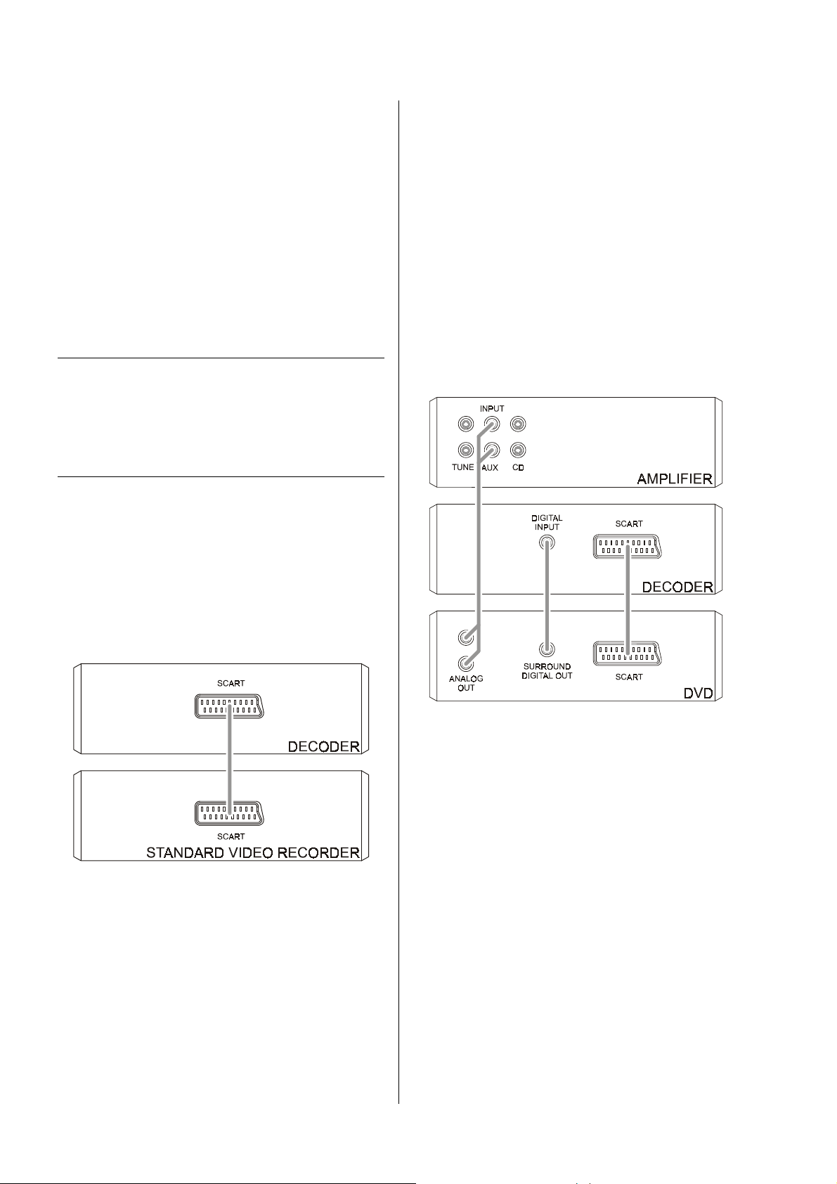
Connecting a
3.
Connecting a DVD player (digital picture source)......................................................................................... 35
4.
Connecting a CD mechanism (digital sound source) ................................................................................... 36
5.
Connecting a set-top box (digital sound and picture source) ....................................................................... 37
6.
Connecting a SAT receiver (analogue sound and picture source)............................................................... 38
7.
SAT receiver (analogue sound and picture source) at the
8.
Video recorder (analogue device with record / playback facilities).............................................................. 40
Variations on standard wiring .................................................................................................................................. 41
Optimising the system ............................................................................................................................................. 42
............................................................................................................................................... 9
............................................................................................................................................ 12
DVD 1210 R
- amplifier with TASI and
............................................................................................................ 23
R
...................................................................................... 33
LINK
AUX-AV
input.................................................... 39
Miscellaneous
Trouble-shooting...................................................................................................................................................... 43
Surround systems - explanatory notes .................................................................................................................... 47
The
Glossary................................................................................................................................................................... 50
Specification ............................................................................................................................................................ 51
surround system....................................................................................................................................... 49
3
Page 4
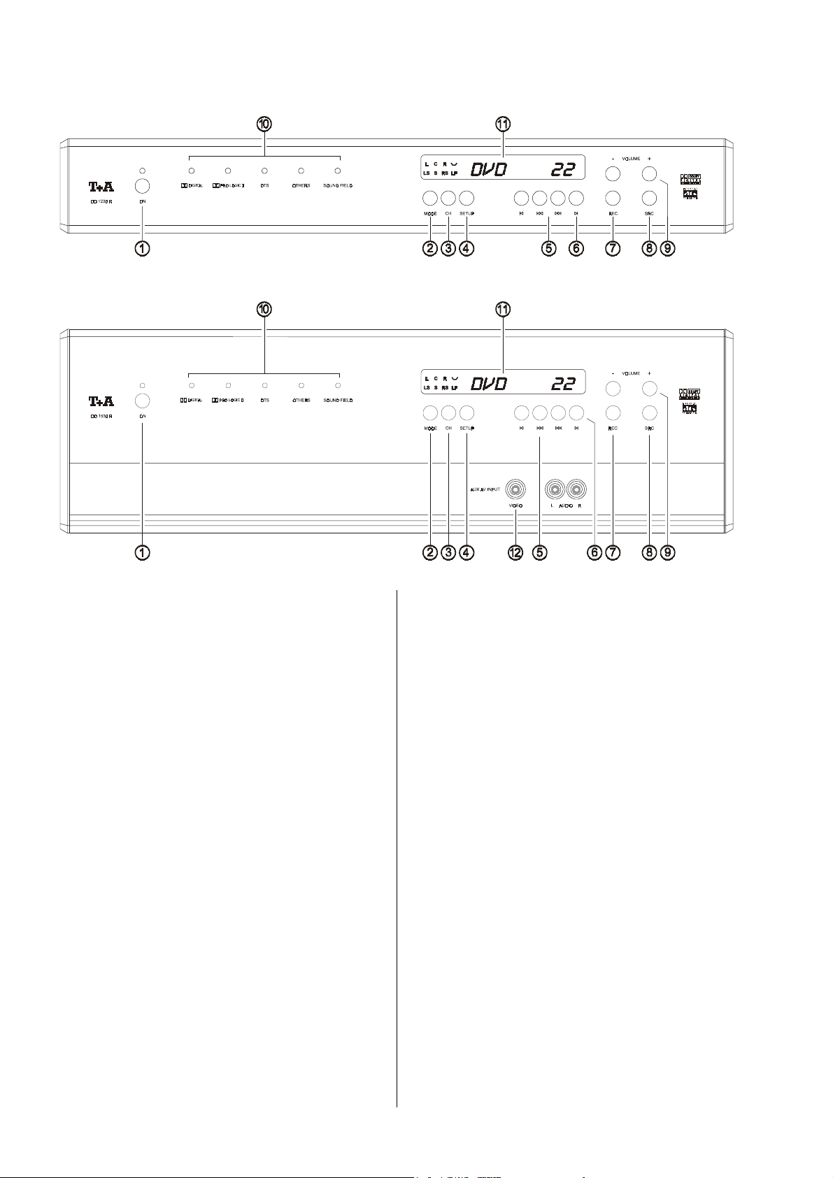
Front panel controls
DD 1230 R
DD 1530 R
The decoder’s mains On / Off switch.
Switching on and off
•
Pressing the mains button
coder on and off. When the machine is switched on
and ready to use, the green LED glows.
Standby and record ready mode
•
If you hold the
second when the decoder is already switched on, the
machine switches to stand-by mode. Video recorder
recordings can be made with the unit in stand-by
mode; the screen displays the recording source you
have selected (see section
the digital surround decoder'
button pressed in for about one
switches the de-
'VCR recordings using
).
.
.
..
Switching to surround mode.
•
If you are in
switches to
three seconds the screen shows the
or the
Selecting the surround mode and sound field.
•
If you press the
the machine displays the next surround mode or the
next sound field. When the three seconds have
elapsed, the decoder screen returns to the normal display.
If you now press the
the new surround mode or sound field for a further
three seconds; i.e. you can still continue to cycle
through the available modes.
Switching to stereo mode.
•
If you
one second when in
switches back to
stereo mode
surround mode
sound field
.
.
..
hold
the
, pressing this button briefly
, and for a period of about
surround mode
currently set.
button again during this period,
.
.
button, the screen shows
..
.
.
button
..
surround mode
stereo mode
pressed in
.
for about
, the decoder
4
Page 5

y
y
yy
This button is designed for possible later function expansions.
Opening the '
•
Pressing
This is where you can change the decoder settings
which are only occasionally required in normal daily
listening: perhaps to allow for temporary changes in the
listening room, or to compensate for unique characteristics of a special listening source.
Opening the '
•
Holding
second opens the
the settings and decoder functions which are rarely
needed, such as level and tone adjustments. Dedicated buttons for functions of this sort are not present,
as it is important that the front panel should be uncluttered.
Main Menu
this button
Device Setup
the
'.
briefly
opens the
'.
button
'
Device Setup
pressed in
'
Main Menu
for about one
'
. This menu contains
–
=
The decoder features a digital volume control: every time
you press one of the volume buttons the volume increases
If you hold one of the volume buttons pressed in for
longer than a second, the volume continues to rise or fall
until you release the button again.
'
.
The screen displays
=
==
Note:
The volume and tone controls of the decoder are completely independent of the corresponding controls on
your
the optimum volume setting for each mode.
stereo pre-amplifier. This allows you to select
+
or decreases
'
'
VOLUME
VOLUME
VOLUMEVOLUME
;
;
;;
briefly.
by 1.5 dB.
T
T
TT
Change buttons
Select buttons
x
x
xx
Cycles through the AV inputs
AUX-AV
short press:
long press:
2
2
22
Cycles through the connected AV source devices *) as
follows:
/
U
U
UU
in the menu control system.
(see section entitled
/
!
!
!!
in the menu control system.
(see section entitled
as follows:
next
previous
'
Menu Control system
'
Menu Control system
TV, DVD, SET-TOP BOX,
AV input
AV input
'
)
'
)
short press:
long press:
*)
Note:
This assumes that you have already entered the AV
source devices in the
'
Source Setup
source device
next
previous
source device
'
.
5
Page 6
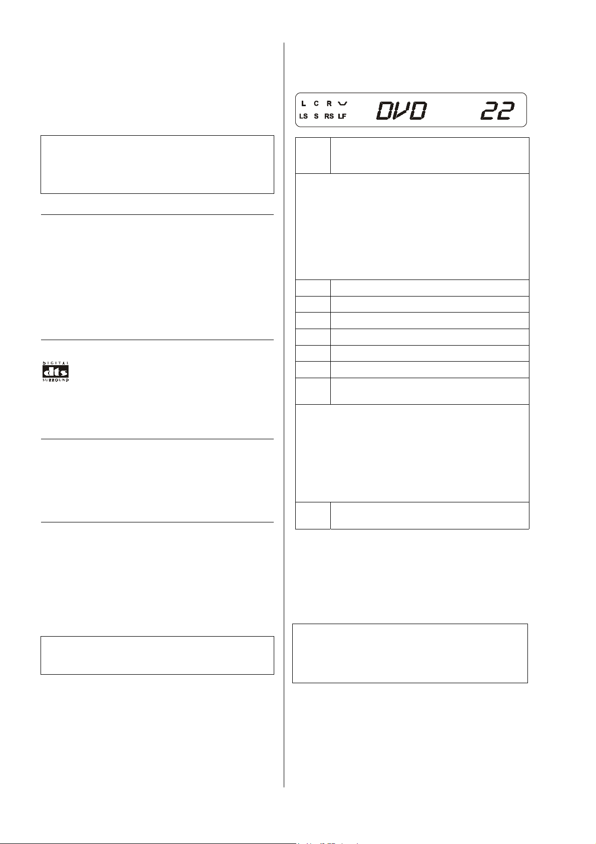
Decoder mode display
DIGITAL
RRRR
The decoder
at the input a digital multi-channel signal which is encoded using Dolby Digital. The corresponding LED
glows.
automatically
selects this mode if it detects
Note:
Some Dolby Digital encoded CDs contain sound signals
encoded with Dolby Surround. The decoder automatically detects this, and uses Dolby Pro Logic II for playback.
PRO LOGIC II
RRRR
The decoder automatically switches to this mode for any
analogue stereo source
material is Dolby Surround encoded. For
sources
matically
permits it. The corresponding LED lights up.
The decoder
at the input a digital multi-channel signal which is dts
encoded. The corresponding LED lights up.
or 2.0 programme material the machine
selects PRO LOGIC II if the recorded material
automatically
if it detects that the sound
digital stereo
auto-
selects this mode if it detects
OTHERS
This display is provided for possible expanded functions
which may be developed in the future.
Integral screen
>>>>
The display elements of the digital surround decoder are
grouped together in a clearly laid out screen:
Alpha-numeric display area, showing mes-
DVD 22
DVD 22
DVD 22DVD 22
The following displays light up when the input signal
contains information relating to the corresponding surround channel - provided that a loudspeaker has been
assigned to that channel in the
sages generated by the decoder (AV source,
current volume etc.)
'
Speaker Setup
'
.
Exception:
The LF (Low Frequency) display also lights up if the
bass part of the signal for other channels has been
routed to the low bass channel; this is carried out by
selecting loudspeakers in the
Main speaker, front left
L
Center speaker, front center
C
Main speaker, front right
R
Surround speaker, rear left
LS
Left and right surround speaker (rear) mono
S
Surround speaker, rear right
RS
LF L
ow Frequency effects channel
(low bass channel)
'
Speaker Setup
'
.
Examples:
(the examples assume that a loudspeaker has been
assigned to each channel)
• If the digital input signal is of the
dts 5.1
type, then the letters
'LF'
and
• If the sound signal is a
then the letters
light up.
2-channel PCM audio
'L'
This symbol lights up when
ume-dependent tone control) is switched on.
and
'R'
light up.
Dolby Digital 5.1
'L', 'C', 'R', 'LS', 'RS'
type,
LOUDNESS
(vol-
or
SOUND FIELD (simulated sound fields)
You can switch on this mode
wish to generate a simulated sound field to give spatial
effects to any stereo source material. The corresponding
LED lights up.
Note:
If the recorded materials is encoded at 96 kHz, the only
modes available are stereo and mono. See
manually
whenever you
'
Main Menu
AUX AV
????
DD 1530 R
(only
Video input and stereo sound input for connecting an
additional AV source device.
(VIDEO and AUDIO CINCH)
)
Note:
The front panel sockets of this
parallel with the corresponding sockets on the back
panel. The front and rear
'
.
fore not be used at the same time!
6
AUX AV
AUX AV
input are wired in
sockets must there-
Page 7

VCR-recordings using the digital surround decoder
x
x
The
recording source independently of the current source
device which you are viewing or listening to.
This facility allows you to record an AV source device
(e.g. SAT receiver) while you
listen to another AV source device (e.g. DVD player).
If you wish to make a timer-controlled VCR recording,
you must first select the appropriate recording source
(e.g. SAT receiver) using the
coder.
At the time the recording is to take place, the decoder
must not be completely switched off (i.e. it must be
switched on or in stand-by mode).
In stand-by mode the decoder confirms its actions by
displaying the selected recording source on its screen in
dimmed form:
Caution:
The record select switch on the decoder does not carry
out any picture format conversion. You must set the
recording VCR to the same picture norm as the recording source.
button on the decoder is used to select a
xx
simultaneously
x
'REC'
and source name.
x
xx
button on the de-
watch or
Automatic power-off:
Normally the decoder switches itself off in parallel with
the master device. If the system is switched to stereo
mode, the screen shows:
'
After two minutes in stereo mode the decoder automatically switches to stand-by mode, as it is redundant in
stereo mode.
You can switch on the decoder again at any time by
<
pressing the
stereo mode.
<
button briefly; it then reverts to
<<
PREAMP
PREAMP
PREAMPPREAMP
'
7
Page 8
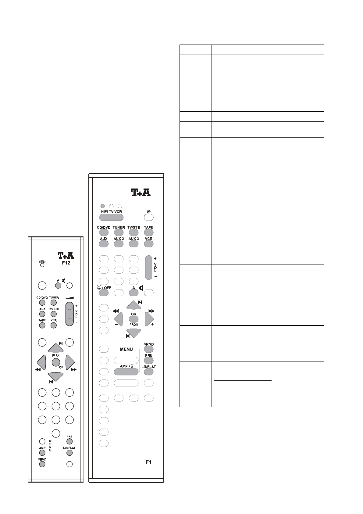
Remote control of the Surround Decoder
General information
The digital surround decoder can be controlled using the
F11
remote control handset, or the F1 system remote
control unit. If you are using the F1 handset, it must first
be switched to Hi-Fi mode.
The decoder receives its remote control commands via
R
LINK
the
switch it on; it switches itself off when the Master device
is turned off.
In the drawings some of the buttons are filled in
(
remote control of the decoder. The other buttons have no
effect on this unit.
master device. Press the
); these are the ones which are required for
button to
[
[
[[
#
#
##
N
N
NN
9
9
99
Z
Z
ZZ
g
g
gg
h
h
hh
=
=
==
j
j
jj
)
)
))
ÌÌÌÌ
ËËËË
ÍÍÍÍ
ÎÎÎÎ
F1 only:
Direct source select button
switch the handset to Hi-Fi mode.
Note:
The F1 remote control handset also in-
d
(
F11
d
dd
) and
'
'
cludes the source buttons
f
f
and
ff
select the same source device.
Volume control rocker
Switches all loudspeaker outputs on and off
alternately.
F1 only:
Multi-function button:
Brief press in stereo mode:
Switches over to surround mode.
If the decoder is switched off,
it is automatically switched on again.
Brief press in surround mode:
Switches to the next AV source
which is assigned to the source button
Long press in surround mode:
Switches to the previous AV source
which was assigned to the source button
Brief press in surround mode:
Switches to stereo mode.
Toggles volume-dependent tone correction
LOUDNESS
(
of the decoder always shows the current
status briefly in text form; the
the display window is the permanent indicator that loudness is switched on.
Select button
trol system
Change button
control system
9
9
.
99
Switches all loudspeaker outputs
off.
'
in the
Source Setup
'
in the
Source Setup
) on and off. The display area
in the decoder’s menu con-
in the decoder’s menu
d
d
dd
.
.
symbol in
e
e
,
ee
(F1)
\
\
\\
8
8
88
(F11/F12)
bzw.
Confirmation button
menu control system
Call up menu function
Brief press: '
Long press: 'Device Setup'
in the decoder’s
Main menu
'
(F1)
8
Page 9

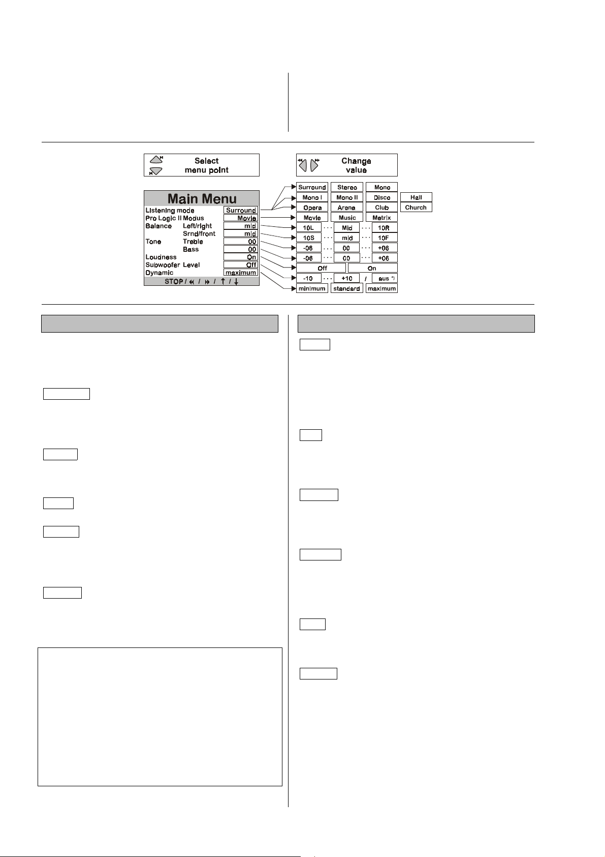
Menu control system
To keep the control panel of the digital surround decoder
as compact and uncluttered as possible, the panel does
not include dedicated buttons for controlling the decoder
functions of tone and level adjustment directly; instead a
menu control system (
'
The
Main Menu
for everyday use of the decoder. You can call it up at any
time by briefly pressing one of the remote control buttons
8
8
88
panel of the decoder.
When you install your surround system, it is important to
set up all the audio and video components and adjust
them to match each other correctly, and to match the
acoustic qualities of your listening room. These tasks are
carried out in the
If a television is connected to the decoder, all the menus
are displayed page by page on the television screen; at
the same time they are displayed line by line on the
decoder’s integral screen.
or
'
Main Menu
'
contains all the functions you will need
, or the
'
Device Setup
'
) is used.
button on the front
'
.
The following table shows how the menu control system
is operated using the remote control buttons, or the buttons on the decoder’s front panel.
Open Main Menu
(press button briefly)
F11/F12 F1 Front panel
8
8
88
F11/F12 F1 Front panel
/
ËËËË
ÌÌÌÌ
F11/F12 F1 Front panel
/
ÍÍÍÍ
ÎÎÎÎ
F11/F12 F1 Front panel
\
\
\\
Select buttons
/
ËËËË
ÌÌÌÌ
Change buttons
/
ÍÍÍÍ
ÎÎÎÎ
Confirmation buttonsr
\
\
\\
T
T
TT
/
!
!
!!
/
U
U
UU
select buttons
• The
tions where you can enter information.
change buttons
• The
tion.
confirmation button
• The
The following section describes the menu points and
explains the adjustment facilities and their effects.
are used to move to pre-set posi-
alter the value at the input posi-
closes the
'
Main Menu
'
.
9
Page 10
Main Menu
'
The
Main Menu
decoder which are only occasionally required for daily
listening; perhaps to allow for temporary changes in the
listening room, or to compensate for unique characteristics of a special listening source.
'
is designed for adjustments to the
Listening mode:
At this menu point you can select the decoder’s playback
mode or sound field which you wish to use.
'remembers' your chosen setting for each input, and
selects it every time you switch to that input.
Surround
multi-channel signal, decodes it and passes it to all the
output channels. The front panel screen displays the
current decoder mode. If the signal is
decoder always uses Dolby Pro Logic II decoding.
Stereo
decoder converts it into a stereo signal, i.e. all channel
information is mixed down and sent to the main left and
right loudspeakers.
Mono
loudspeaker channel.
Mono I
Generally
The signal from Channel I is reproduced via the Centre
loudspeaker *);
sed.
Mono II
Generally
signal from Channel II is reproduced via the Centre
loudspeaker *);
sed.
Note:
*) If no Centre speaker is present (see
Menu
right main speakers.
Not all signal sources (DVDs, CDs etc.), which are Dolby
Digital or dts Digital Surround encoded contain full 5.1
information. Even if the screen indicates that a particular
channel is present, this does not necessarily mean that
the loudspeaker in question will always produce sound.
In every playback mode signals may be present on the
subwoofer channel; this depends on the loudspeaker
arrangement you have selected in the
The decoder detects an encoded
Even if a multi-channel signal is detected, the
All channels are mixed down onto the center
Mode for two-channel TV sound
Channel I
Mode for two-channel TV sound
Channel II
'
), the Centre channel is mixed onto the left and
transmits the synchronised sound.
Channel II
Channel I
(original sound) is suppres-
transmits the original sound. The
(original sound) is suppres-
The decoder
digital
analogue
'
Loudspeaker
'
Speaker Setup
, the
'.
or
'
Main Menu
To open the
8
8
88
decoder’s front panel.
'
press the remote control button
briefly, or the
button on the
Sound fields:
Disco
viding an even spread of sound over a dance floor, using
the front and surround loudspeakers. The sound signal is
mixed and passed to the front and surround speakers
without reflections and delays, and with equal power.
The strongly concentrated sound reproduction generates
an immediate, energy-charged atmosphere which is a
great choice for any party.
Hall
from all directions. Ideal for playing back recordings of
large orchestras, or simulating the live atmosphere of a
large rock concert hall - an excellent choice for very
dynamic rock music.
Theatre
tion with the full sound of an orchestra, but without exaggerated reverberation. The spatial sound towards the
rear is slightly limited, in the interests of better orientation.
Stadium
ence” in the front area, helping to localise commentators
and dialogues on the screen. Sound from the rear is
designed to give the impression of being amongst the
spectators in the stadium. This sound field is also suitable for TV shows and music programmes.
Club
club, with a pattern of reflections dominated by large
floor and wall surfaces. Also good for simulating small
halls.
Church
church, with long reverberation times. This sound field is
an excellent choice for sacred organ music.
This sound field is particularly suitable for pro-
Reverberant concert hall with sound reflections
This program combines clear voice reproduc-
This sound image concentrates the “pres-
The characteristic atmosphere of a cellar jazz
Simulation of the acoustic conditions in a large
10
Page 11

ProLogic II mode:
This menu point enables you to set the Dolby ProLogic II
decoder to suit varying programme material.
Movie
Music
Matrix
for films
for music
for mono programme material
Balance left/right and front/surround:
These two menu points allow you to set a temporary
change in the balance between the left/right and
front/rear loudspeakers, in order to compensate for a
temporary listening position which is less than perfect.
You can alter the balance in 1 dB increments, and the
current value is displayed in the following form:
10L
(left) . . . . . . . .
10R
(surround) . . .
Center
(neutral position)
10R
10F
(right)
(front)
Note:
It is important to start by setting the correct balance for
the “standard” listening position, adjusting the volume of
the front, surround and center channels. This task is
carried out in the
'
Speaker Balance Setup
'
.
Tone: treble and Tone: bass:
These two menu points allow you to set a temporary
change in the treble and bass settings in order to compensate for tonal differences in the recorded material.
The setting affects all channels, and the range of adjustment is +/- 6dB in 1 dB increments. The current value
is displayed on the screen; 00
ting'
.
dB means
'Linear set-
Subwoofer level:
'
off
, in
. You
If you switch on the subwoofer in the 'Speaker Setup
this menu point you can adjust its level within the range 10 (dB) to +10 (dB) in order to match its volume to the
acoustic conditions in your listening room, and to match
the volume of the other channels.
If the subwoofer is switched off in the
this menu point in the
cannot adjust the subwoofer level in this situation.
'
Main Menu
'
Speaker Setup
'
shows
Note:
It is important to start by setting the correct balance between the other channels (front, rear and center). This
task is carried out in the
'
Speaker Balance Setup
'
.
Dynamic range:
The dynamic range is the difference in volume between
the quietest and loudest passages of a recording. The
original sound track of a film usually features a very wide
dynamic range, and the decoder is capable of reproducing the full range.
Unfortunately not every listening room can cope with the
full dynamic range which the decoder is capable of reproducing. You also have to consider your neighbours,
especially in the late evening.
To cope with these problems it is possible to reduce the
dynamic range of Dolby Digital encoded sound material
in three stages. The result is that quiet passages (e.g.
low-level conversations) are reproduced slightly louder
when the volume is set low, whereas loud passages (e.g.
gigantic explosions) are slightly reduced in volume.
The following dynamic ranges are available:
standard
highly compressed dynamic range, e.g. for
playing at night-time.
'
,
Note:
It is important to start by establishing the correct tone
settings for your room, to allow for imperfect loudspeaker
positioning or room influences. This task is carried out in
'
the
Tone Control Menu
'.
Loudness:
Toggles volume-dependent tone correction
LOUDNESS
(
coder always shows the current status briefly in text
form; the
manent indicator that loudness is switched on.
) on and off. The display area of the de-
symbol in the display window is the per-
high
standard setting, moderate compression of
dynamic range.
full
exploits the full dynamic range which the
sound source makes available.
Note:
Any adjustment to the dynamic range only affects Dolby
Digital encoded sound sources.
11
Page 12
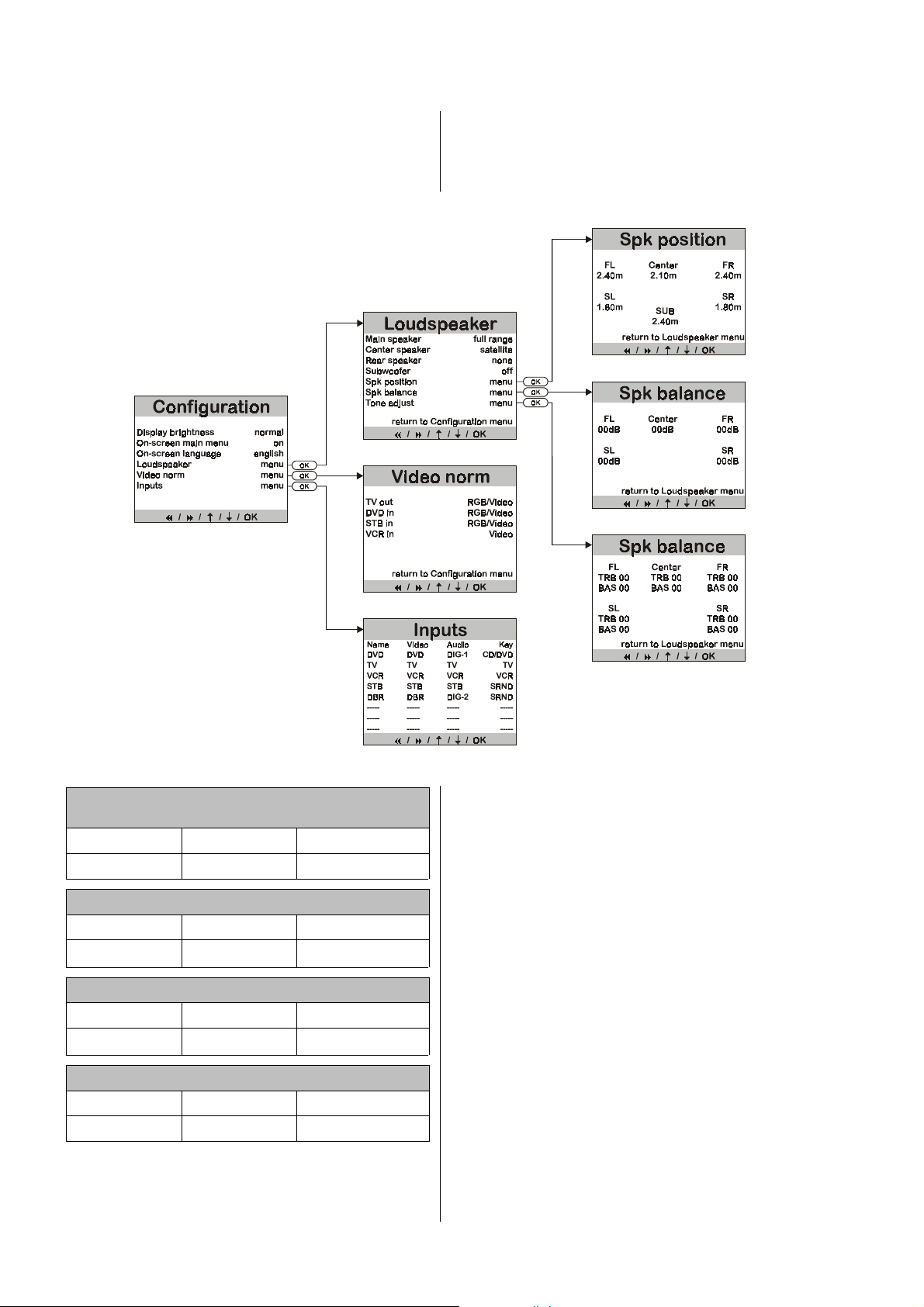
System Configuration
'
In the
Device Setup
the audio and video components of your surround system so that they match each other perfectly, and at the
same time set them to suit the acoustic characteristics of
your listening room.
'
you can adjust the settings for all
Summary of ‘Device setup‘
This procedure only needs to be carried out when you
are installing the system, or when you are adding or
replacing individual components of the system. The
following diagram shows the menu structure.
Open Device Setup
(hold button pressed in)
F11/F12 F1 Front panel
8
8
88
F11/F12 F1 Front panel
/
ËËËË
ÌÌÌÌ
F11/F12 F1 Front panel
/
ÍÍÍÍ
ÎÎÎÎ
F11/F12 F1 Front panel
\
\
\\
Select buttons
/
ËËËË
ÌÌÌÌ
Change buttons
/
ÍÍÍÍ
ÎÎÎÎ
Confirmation buttons
\
\
\\
T
T
TT
/
!
!
!!
/
U
U
UU
The table on the left shows how the menu system can be
controlled using the remote control buttons or the buttons
on the front panel of the decoder.
select buttons
• The
tions where you can enter information.
change buttons
• The
tion.
• If there is a further menu name at the data input position, then pressing the
the corresponding sub-menu. Otherwise the
tion button
All menus are displayed page by page on the screen of a
television set (if connected), and at the same time line by
line on the decoder’s integral screen.
The following section describes the menu points and
explains the adjustment facilities and their effects.
closes the menu.
are used to move to pre-set posi-
alter the value at the input posi-
confirmation button
calls up
confirma-
12
Page 13
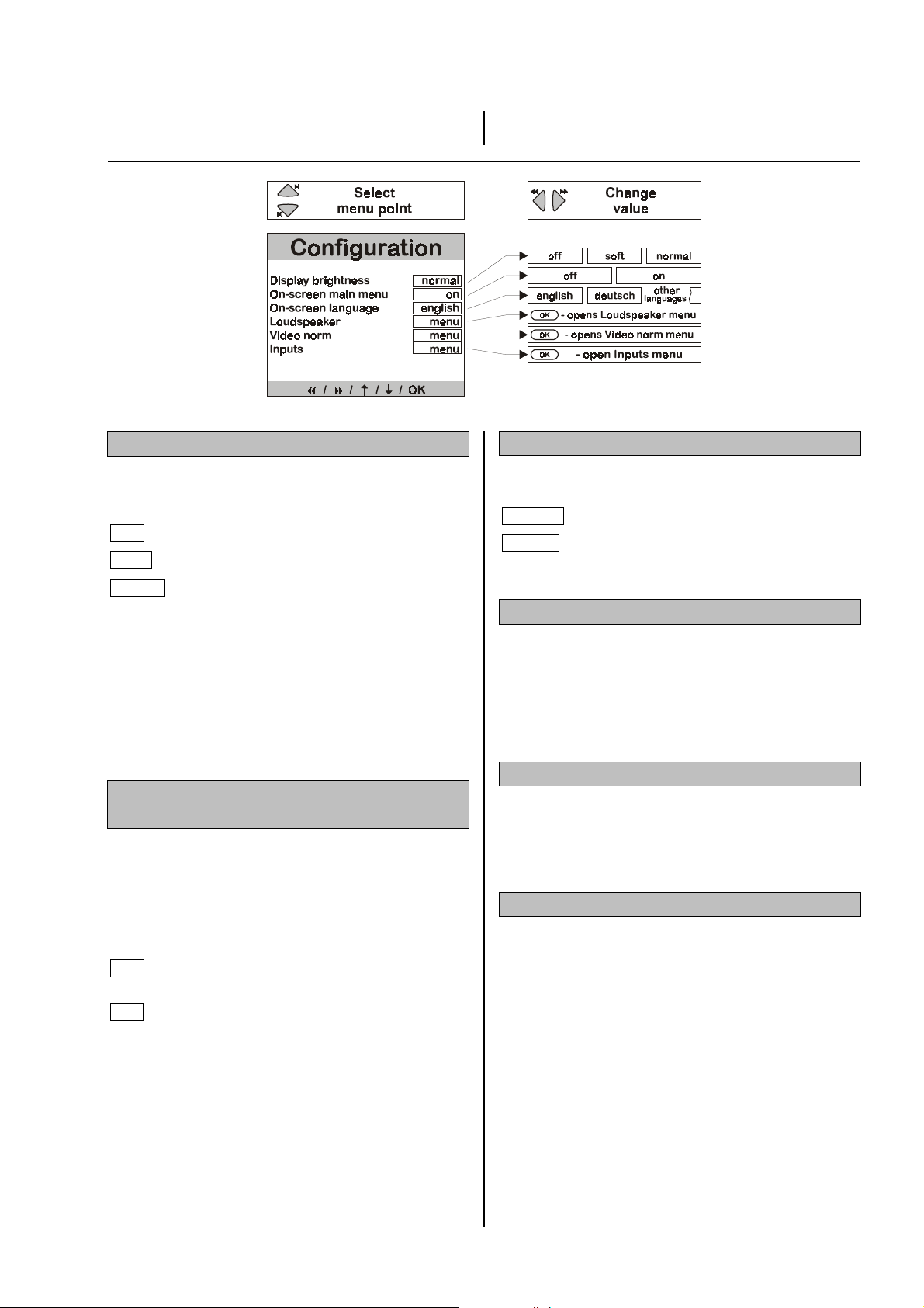
Device Setup
You can call up the
mote control button
'Device Setup'
8
8
88
or
by pressing the re-
, or the
Screen brightness:
The brightness of the screen can be set to suit your
personal preference. Three brightness levels are available:
off
soft
the screen is completely switched off.
subdued setting, for dark locations.
button on the front panel of the decoder; in either case
hold the button pressed in for about two seconds.
On-screen language:
The on-screen menus can be displayed on the TV
screen in German or English.
deutsch
english
The on-screen menus appear in German.
The on-screen menus appear in English.
normal
If you set either of brightness levels 1 and 2, the screen
switches briefly to normal brightness every time you give
a command, so that you can check the settings easily
even from a distance. After about four seconds the
screen automatically switches back to your preferred
brightness level. If you change the brightness level, this
also means that the new value only becomes effective
after about four seconds.
clearly legible, even in sunlight.
Switching the on-screen main menu on
and off:
If you just wish to make a temporary change to the balance or tone, it is not absolutely necessary to call up the
'
Main Menu
on what you are watching; in most cases the display on
the decoder’s screen is quite adequate. At this menu
point you can switch the TV on-screen main menu display on and off.
off
on
'
on the television screen and superimpose it
'
The
Main Menu
decoder’s screen, but not on the TV screen.
'
The
Main Menu
and also line by line on the decoder’s
screen.
'
appears line by line on the
'
appears on the TV screen
Loudspeaker
'
The
Speaker Setup
output signals to the loudspeakers in your surround system. At the same time you can adjust the output of the
speakers accurately to suit the acoustic and spatial
characteristics of your listening room.
:
'
provides the means to balance the
Picture norm:
'
In the
Video Setup
to match the picture sources connected to all the decoder’s video inputs and outputs.
Source
The purpose of the
sources connected to the decoder into the overall operating system of the typical ‘R’ system. This is done by
assigning a name to every AV source which is connected
to the decoder; those names are then used from that
point on in all the decoder’s on-screen messages. You
can then define the
sockets
nected. Finally it is possible to assign every AV source to
a
the various machines can be selected when the system
is set to
:
) on the decoder to which each device is con-
source button
surround mode
'
you can set the correct picture norm
'
Source Setup
audio / video input socket (or
on the remote control handset, so that
.
'
is to integrate the AV
13
Page 14
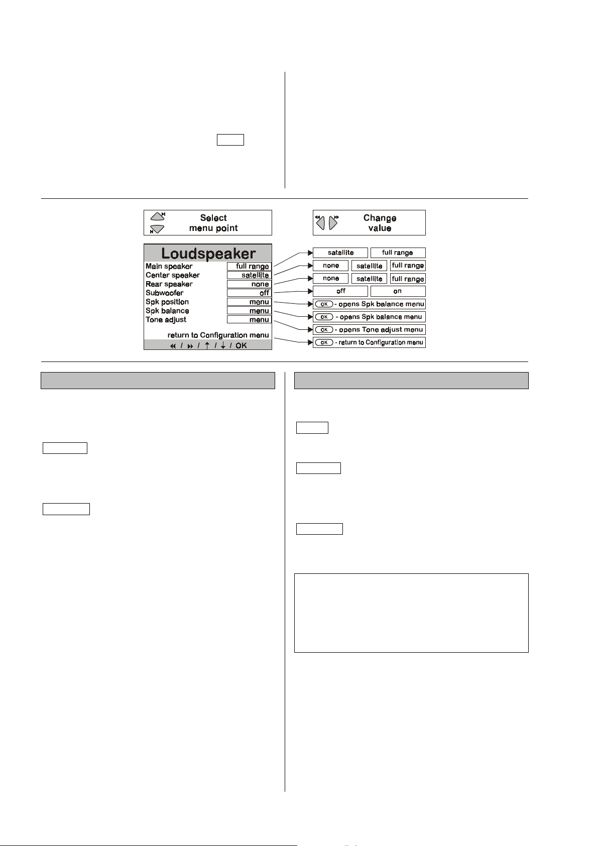
Speaker Setup
The first purpose of the
to distribute the output signals correctly to the loudspeakers which form part of your surround system.
If your system does not include a “full set” of supplementary loudspeakers (center, rear and subwoofer), it is
important to mark the missing items as
'
Speaker Setup
The corresponding sound signal is then mixed down onto
those channels which are present (
'.
'
Speaker Setup
'
is to allow you
Downmix
none
).
in the
The last three menu points enable you to adjust the
loudspeakers to suit the acoustic and spatial characteristics of your listening room.
Adjustments should only be made to these settings when
you are installing the system, if you are adding, replacing
or moving individual loudspeakers, or if the acoustic
conditions in your listening room are changed (e.g.
changes to the furniture, carpets, curtains etc.).
Main size:
Defines the size and bass capacity of the main left and
right front loudspeakers. Select one of the following settings: *)
satellite
full range
for small speakers whose bass reproduction is necessarily restricted. The low bass
content (below 80 Hz) of the main channel
signals is mixed down onto the subwoofer,
if present.
for larger speakers. The full frequency
range is passed on to the main speaker
channels without restriction.
Center size:
Defines the size and bass capacity of the center
speaker. Select one of the following settings: *)
none
satellite
full range
Note:
If your system does not include a center speaker, the
main loudspeakers should be set up not too far away
from the TV set, and ideally should be arranged symmetrically about it, otherwise it will be very difficult to localise
dialogues on the television screen.
if no center loudspeaker is present. The
center channel is mixed down onto the left
and right main loudspeakers.
for small speakers whose bass reproduction is necessarily restricted. The low bass
content (below 80 Hz) of the main channel
signals is mixed down onto the subwoofer,
if present.
for a center speaker of about the same
size as the main loudspeakers. The full
frequency range is passed on to the center
channel without restriction.
14
Page 15

Rear Size:
Subwoofer:
Defines the size and bass capacity of the rear surround
loudspeakers. Select one of the following settings: *)
none
if no surround loudspeakers are present. The
surround channels are mixed down onto the
left and right main loudspeakers.
Note:
Genuine surround reproduction is not possible without
rear speakers!
satellite
full range
for small speakers whose bass reproduction
is necessarily restricted. The low bass content
(below 80 Hz) of the main channel signals is
mixed down onto the subwoofer, if present.
for speakers which offer very good bass
reproduction. The full frequency range is
passed on to the surround channels without
restriction.
*) Note:
To avoid nonsensical settings, the system does not allow
you to set all the possible combinations (
ter
Rear LS
and
dard combinations, but you can modify them individually
1. Main, center and rear size: .......
). The following list shows all the stan-
Standard combinations
Subwoofer: ...............................
Front LS, Cen-
Satellite
on
In this menu point you set whether a subwoofer is present in your loudspeaker system. Select one of the following settings:
on
If a subwoofer is present. The signals in the
Low Frequency effect channel (
other low-frequency bass signals (below
80 Hz) which are not within the compass of
the full-range loudspeakers, are passed to the
subwoofer channel.
off
If no subwoofer is present. The signals from
the Low Frequency effect channel (
all other low-frequency bass signals (below 80
Hz) are mixed down onto the main loudspeakers.
Note:
Provided that you have
'
the
Speaker Setup
'
Main Menu
that the volume of the subwoofer matches the volume of
the other channels.
'
within the range -10 (dB) to +10 (dB), so
switched on
'
, then you can adjust its level in the
the subwoofer in
Speaker position:
Activating this menu point leads to a further menu in
which you can define the position of the loudspeakers,
.
i.e. you can enter the distance from the listening position
to each loudspeaker separately. This enables the decoder to compensate for timing discrepancies due to
differences in speaker location (see
'
).
Setup
'
Speaker Position
LFE
), and all
LFE
) and
2. Main size: .................................
Center and rear size: ...............
Subwoofer: ...............................
3. Main and rear size: ...................
Center size: ..............................
or ........................
Subwoofer: ...............................
Full range
Satellite
off
Full range
Full range
Satellite
on
Noise sequencer:
Activating this menu point leads to a further menu in
which you can set the balance between the volume of all
the loudspeakers (see
'
Speaker Balance Setup
'
).
Tone adjust:
Activating this menu point leads to a further menu in
which you can adjust the tonal balance of the loudspeakers (see
'
Tone Control Menu
'
).
15
Page 16
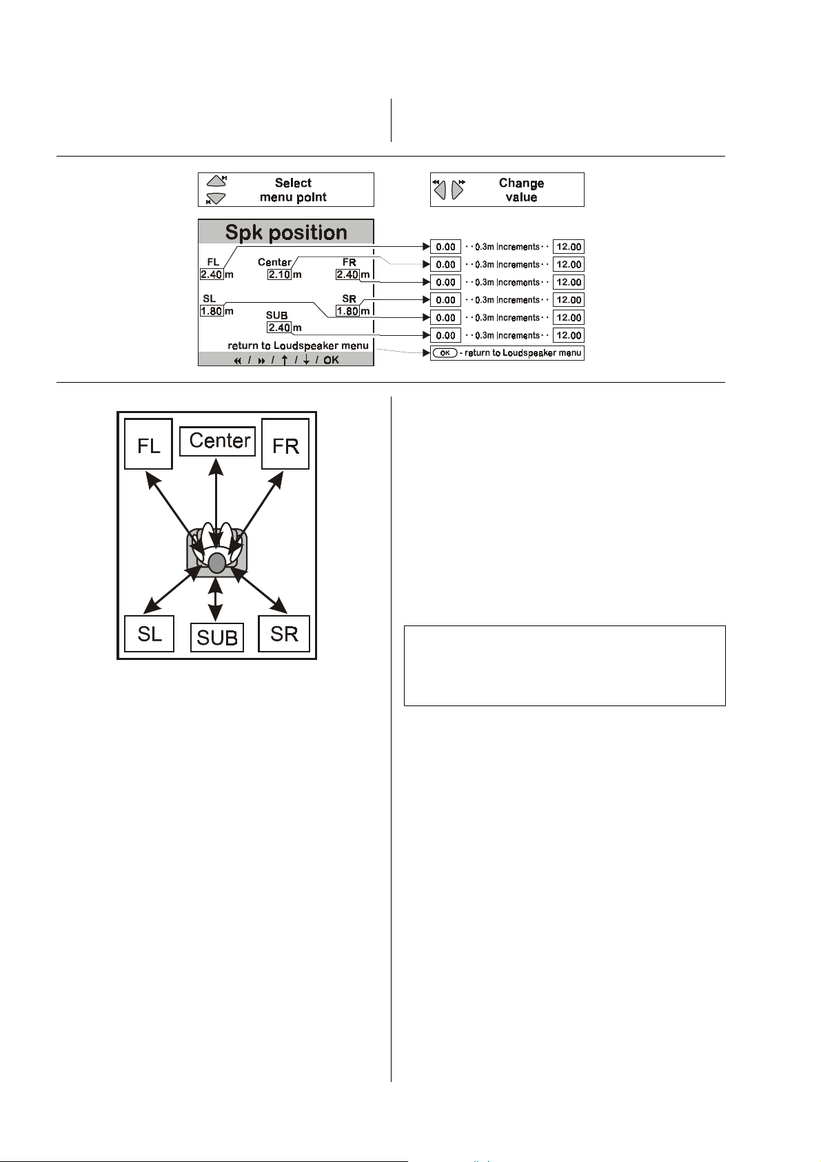
Speaker Position Setup
'
In the
Speaker Position Setup
tance from the listening position (in 0.3 m increments) for
each loudspeaker separately.
'
you can enter the dis-
This enables the decoder to compensate for timing discrepancies due to differences in speaker location.
As the illustration shows, you use the select buttons to
move to the input positions in the following sequence.
Output channels not in use (see
not be edited.
• Main loudspeaker front left (FL)
• Center loudspeaker front center (
• Main loudspeaker front right (FR)
• Surround loudspeaker rear right (SR)
• Surround loudspeaker rear left (SL)
• Active subwoofer (any position) (
'
Speaker Setup
'
) can-
Center
Sub
)
)
Measure the distance between the listening position and
the loudspeakers in your surround system, and enter the
measured distances.
Use the change buttons to enter the measured distance
in increments of 0.3 m.
Note:
The maximum distance of a loudspeaker to the listening
position is 12 m. For acoustic reasons greater distances
cannot be recommended, and the system cannot compensate for timing errors over a range greater than 12 m.
16
Page 17

Speaker Balance Setup
To ensure that the decoder supplies a balanced sound
image, the system allows you to adjust the volume of the
individual channels to provide a harmoniously balanced
arrangement.
When you activate the
hear a hiss from the left main loudspeaker lasting two
seconds. You will find the data input position after the
first menu point.
As the illustration shows, the hiss is reproduced on all
the channels in turn, in each case lasting about two seconds:
• Main loudspeaker front left (FL)
• Center loudspeaker front center (
• Main loudspeaker front right (FR)
• Surround loudspeaker rear right (SR)
• Surround loudspeaker rear left (SL)
The system skips any output channels which are not in
use (see
When the hiss is sounding on a particular channel, the
on-screen menu indicates the corresponding input position. You can now alter the value within the range
to
hear the result of any change you make.
If you alter the volume, the hiss continues on that channel for a further two seconds before moving on to the
next channel. The input position then changes accordingly.
'
Speaker Setup
+10
using the change buttons. You can immediately
'
Speaker Balance Setup
'FL: 00
'
.
'
).
'
you will
Center
–10
The purpose of the
the level of all the channels.
You can override the automatic cycling process by selecting a particular channel using the select buttons; you
can then adjust its level as you wish.
Take your time to set all the channels to give as even an
impression of volume as possible!
'
Speaker Balance Setup
Note:
The hissing sound used for this is not suitable for assessing bass volume; the volume of the subwoofer
channel can be adjusted in the menu point
)
'
, which is part of the
level
The levels you set for each channel are stored for use
when the surround system has been selected, and applies to all surround modes.
'
Main Menu
'
.
'
is to adjust
'
Subwoofer
17
Page 18

Tone Control Menu
The decoder features an active tone control system
(+/- 6 dB) whose purpose is to compensate for the unwanted influence on playback quality of your listening
room, or of imperfect loudspeaker positions.
The first step is to select a sound source which you wish
to use as the basis for adjusting the tone controls. Make
sure that the sound source you choose is active on all
the channels, so that the sound image is typical of your
listening habits, and any changes you make to the tone
controls are immediately audible in that setting.
Once you have activated this section of the menu, you
will find the data input position after the first menu point.
'FL TB: 00
You can now alter the value within the range
+06
using the change buttons; any change you make is
immediately audible.
Select the input position using the select buttons.
As the illustration shows, you can cycle through the input
positions in the following order:
Output channels not in use (see
not be edited.
'
.
'
Speaker Setup
–06
'
) can-
to
The treble / bass balance can be adjusted separately for
all the output channels, and can therefore compensate
for problems caused by the location of individual speakers.
• Main loudspeaker front left Treble (TB)
• Main loudspeaker front left Bass (BS)
• Center loudspeaker front center Treble
• Center loudspeaker front center Bass (BS)
• Main loudspeaker front right Treble (TB)
• Main loudspeaker front right Bass (BS)
• Surround loudspeaker rear right Treble (TB)
• Surround loudspeaker rear right Bass (
• Surround loudspeaker rear left Treble (TB)
• Surround loudspeaker rear left Bass (BS)
Set values for treble
which gives as well-balanced a sound image as possible.
(TB)
and bass
(BS)
on all channels
(TB)
BS)
Note:
Adjusting the tone controls has an influence on the overall level of that channel. After making a change here we
recommend that you call up the
'
again so that you can check the balance of all
Setup
channels and make corrections if necessary.
'
Speaker Balance
18
Page 19

Video Setup
Optimum picture quality is only possible if the picture
norms of all the video components in the system are set
up to match each other, and if the correct cables
(SCART, video-coax) for the selected picture norm are
used. In the
for all the decoder’s video inputs and outputs to match
the capabilities of the devices connected to it. Many AV
source devices can generate a picture signal using different picture norms (Video, S-Video, RGB), and in this
case the picture norm you wish to use must often be set
in a menu on the AV source device. If you are not sure of
this, study the operating instructions supplied with the
source device and the TV set.
'Video Setup'
you can set the picture norm
There is a large number of different picture norms on the
market, but not all of them are supported by all AV
source devices and TV sets. The decoder is designed to
handle the most widely used picture norms: Video, SVideo and RGB; RGB provides the best picture quality.
The least problematic arrangement is for all the components to use the same picture norm. If the TV set connected to your surround system has a priority RGB circuit, mixed operation is also possible (e.g. DVD player «
RGB, Set-top box « Video; VCR « S-Video);
ample
.
see ex-
TV out:
RGB / Video
S-Video
DVD in:
RGB / Video
S-Video
Set-top in:
RGB / Video
S-Video
VCR in:
For TV sets with RGB or Video sock-
ets.
For TV sets with S-Video sockets.
If the DVD supplies an RGB and Video
signal.
If the DVD supplies an S-Video signal.
If the set-top box supplies an RGB and
Video signal.
If the set-top box supplies an S-Video
signal.
Example:
In the example mentioned above, the
should be set to
cally converts the incompatible S-Video signals to the
Video format.
RGB / Video
. The decoder automati-
TV out
output
Note:
Some AV source devices make available a switch voltage at their SCART output which switches the TV set
connected to it from television reception to SCART picture and sound reproduction; it can also be used to
change the picture format (4:3 / 16:9). Different makes of
TV set interpret the switch voltage in different ways; see
your TV operating instructions for details.
RGB/Video
• In
the source device is passed on to the TV out socket
unchanged.
S-Video
• In
voltage at the TV out socket permanently.
If compatibility problems arise between the TV set and
the AV source devices connected to the system, we
recommend that you use the standard Video norm for all
the machines, as this is generally supported by all devices. Look at
mode the switch voltage produced by
mode the decoder switches on the switch
'
Trouble-shooting
'
.
Video
S-Video
If the video recorder
Video signal
If the video recorder supplies an SVideo signal
only
supplies a
19
Page 20
Source Setup
The purpose of the
source devices connected to the decoder into a
system. For this purpose the sources are sub-divided
into three groups:
1.
High-quality pure
2. A/V sources
3. Combination sources
both a picture and
To ensure that sound and picture quality are always
optimum, these device groups are integrated into the
system in different ways (see also the section enti-
'
The
tled
following points:
Stereo sources
rectly to a pre-amplifier input. They are selected by the
corresponding source button on the front panel, or on the
remote control handset.
'
Source Setup
stereo sources
(picture and sound),
; i.e. machines which supply
high-quality
Surround System
(e.g. tuners) should be connected di-
'
is to integrate the AV
'R'
(sound only),
stereo sound.
'
). Please note the
AV source devices
Combination source devices
set-top boxes) provide both an analogue stereo signal
and a digital surround signal.
The
connect the analogue stereo output of a combination
source device to a pre-amplifier input.
For example, if your DVD player is playing a DVD in
surround mode
decoder via a SCART lead, and the sound signal via a
digital connection.
In surround mode you select the DVD player by pressing
the
button on the remote control handset.
If you have assigned the DVD player to a direct select
button in the
rectly by pressing the appropriate source button.
surround design philosophy enables you to
, the picture signal is passed to the
2
2
button on the front panel, or the
22
'
Source Setup
(e.g. DVD players and
'
, then you can select it di-
A/V sources
connected directly to one of the decoder’s AV inputs
(SCART or Cinch). They can then be selected by the
2
2
22
ton on the remote control handset.
If you have assigned the source device to a direct select
button in the
rectly by pressing the appropriate source button.
(e.g. standard video recorders) should be
button on the front panel, or by the
'
Source Setup
'
, then you can select it di-
but-
CDs can be played on the DVD player in high-quality
stereo mode
this situation the decoder is removed from the signal
path.
In stereo mode you select the DVD player by pressing
the corresponding source button on the pre-amplifier’s
front panel, or on the remote control handset.
via the direct connection to the amplifier; in
20
Page 21
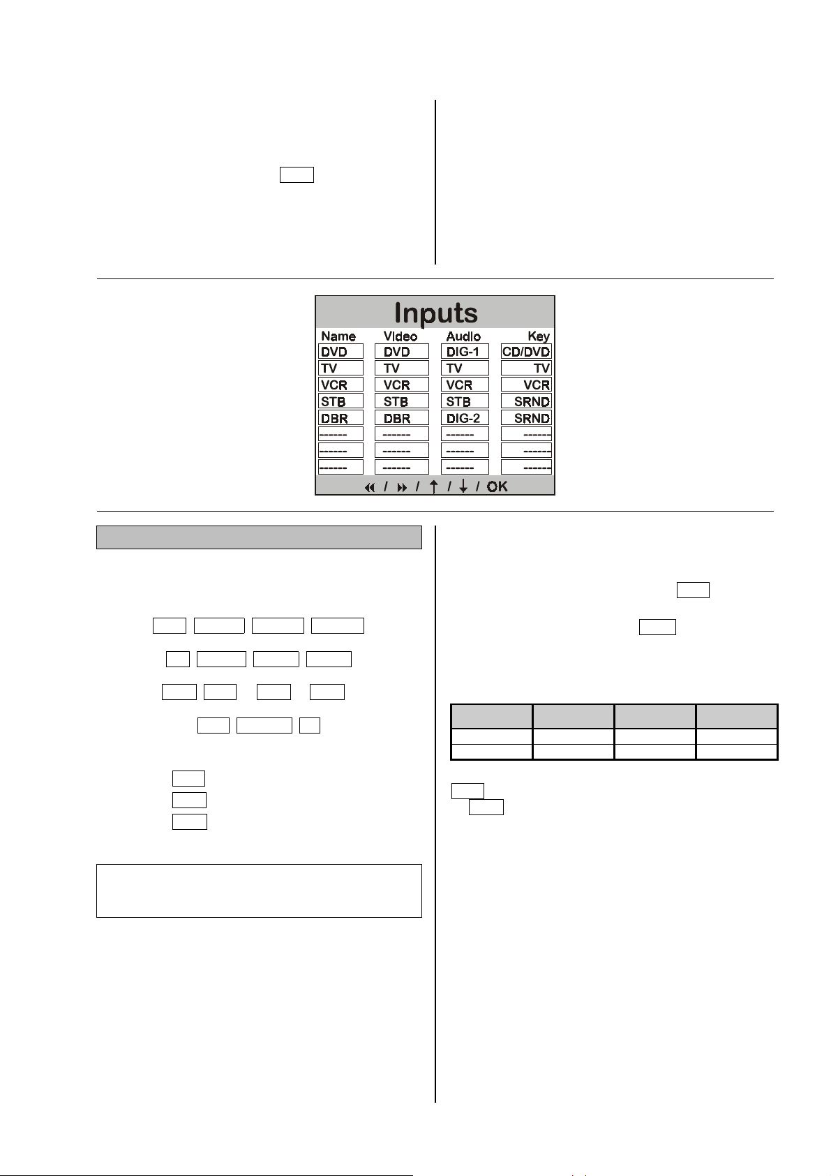
Source Setup
In the first column of the
assign a name to every AV source device which is connected to the decoder.
The device then appears on the decoder’s screen under
source device name
this
when you select it.
In the second and third column you set the signal route
for the AV source, i.e. you define the
input socket
on the decoder to which it is connected.
'
Source Setups Menu
VCR
(e.g.
for videorecorder)
audio
or
'
you
video
In the fourth column you assign a
remote control handset to the AV source device; you can
then press that button to select the source device in
surround mode.
If you do not assign a source button to the AV source
device, you can still select that device in surround mode
by pressing the
button repeatedly.
source button
on the
Name
The permitted names for AV source devices are as follows:
CD
TUNER TAPE-1 TAPE-2
TV AUX-1 AUX-2 AUX-3
DVD STB
STB
1)
VCR
2)
DBR
3)
1)
5.1
AUX-AV
¹ Set-top box
¹ Video recorder
¹ Digital Broadcast
VCR
2)
(1st column)
DBR
---
3)
Note:
Some AV sources feature separate video / audio outputs
for different modes of operation; see following example.
Example:
A set-top box can be used in different ways:
• For television reception with analogue sound (picture
STB
and sound signals via SCART cable
• For digital radio reception (digital sound via one of
'
DIG2
).
the decoder’s digital inputs
e.g. radio text via SCART).
To allow for this facility, it is possible to enter the same
AV source device more than once in the table, using
different names and connection configurations.
Name Video Audio Key
STB STB STB TV
DBR STB DIG2 AUX2
In the example above the set-top box is entered as
STB
for television reception with analogue sound, and
DBR
as
In each case the picture is then passed on via the
SCART connection
logue) or
In surround mode you can select each reception mode
by means of separate source buttons (see
Setup
for digital radio.
STB
DIG2
(digital), depending on selected mode.
'
, section entitled
, and the sound via
'
Button
).
; picture signals
STB
(ana-
'
Source
21
Page 22

Video
In this column you enter the decoder’s
which each AV source device is connected. The follow-
Video
ing
decoder inputs are available:
DVD STB VCR TV AUX-AV
(2nd column)
video input
---
to
Note:
You must also assign the appropriate video norm in the
‘Video Setup’.
Audio
In this column you enter the decoder’s
which each AV source device is connected. The follow-
Audio
ing
1)
The system automatically enters
devices which are connected directly to the
amplifier
decoder inputs are available:
DIG1
DVD STB VCR TV AUX-AV 5.1
DIG2 DIG3 DIG4 DIG5
1)
TASI
.
(3rd column)
audio input
TASI
for all source
to
stereo
Key
The source devices connected to the decoder can be
selected by repeatedly pressing the
the front panel, or the
trol handset.
For devices which you will use very often, you can enter
a direct select button, e.g.
In that case you can directly select the source device in
surround mode using the source buttons defined at this
point, instead of pressing the
repeatedly.
In this column you can enter any of the following source
buttons on the remote control handset:
CD
TV AUX-1 AUX-2 AUX-3
Every
address which the system automatically takes into account when you assign the source buttons. For example,
a CD player has the remote control address
tuner the remote control address
then automatically assigns the source button CD
the CD player, and the source button
tuner.
Several
mote control address.
-source device has its own remote control
source devices allow you to alter their re-
button on the remote con-
AUX1
2
2
22
TUNER TAPE-1 TAPE-2
SRND
*)
(4th column)
2
2
22
for the DVD player.
or
'TUNER'
button on
button
'CD'
, and a
. The system
TUNER
to a
to
Note:
If you select a video input (
AUX-AV
or
second column, the system automatically enters the
same input as the analogue audio input.
If the device in fact has a digital output, you can alter this
entry manually.
) for the current AV source device in the
DVD STB VCR TV
Example
The DVD player can be set to the address
address
the DVD player. In this case you obviously have to assign the DVD player either to the source button CD
the source button
control address you have selected.
Each device to which you have assigned a source button
on the remote control handset (
be selected in surround mode by means of the corresponding source button.
*) If you assign the source button
:
'AUX'
by means of a switch on the back panel of
AUX1
, depending on the remote
. . .
#
#
##
SRND
device, it will have
devices can then be selected by repeatedly pressing
2
2
the
22
rent source device name is displayed on the decoder’s screen.
or
no direct select button
button. In each case the cur-
‘CD’
or the
f
f
ff
to a source
) can
. These
or
22
Page 23

Source Setup
Notes on wiring and assigning sources:
• Connect the analogue stereo output of the DVD
player directly to the pre-amplifier input
• Connect the picture signal to the decoder’s
socket using a SCART lead.
• Connect the sound signal to the decoder’s digital
DIG 1
input
• Complete the
• Move the switch marked
panel of the DVD player to the
• Make the following settings in the
1st column:
using a digital lead.
R
connections.
LINK
ADDR
R
LINK
AUX
position.
'
Source Setup
Enter the name by which the source
device is to be displayed on the decoder’s screen when you select it;
DVD
select
.
(Example: Integrating a
AUX 1
.
DVD
on the back
'
:
DVD 1210 R
Source selection
- If you repeatedly press the
remote control handset (or the
the front panel), you can select all the decoder’s
inputs in turn. In each case the name of the
source device is displayed on the screen.
- Pressing the remote control source button
d
d
or
the source device name
screen.
• If you wish to switch the system back to stereo mode,
briefly press the
handset, or hold the
pressed in for about one second.
selects the DVD player directly, and
dd
)
)
))
.
.
..
)
'DVD'
button on the remote control
button on the decoder
button on the
2
2
button on
22
9
9
99
appears on the
2nd column:
3rd column
4th column:
When you have completed the assigning process in
the '
Source Setup
works as follows in normal daily usage:
stereo mode
• In
d
d
or
dd
source device
• A brief press on the
control handset, or the
coder, switches the system to
decoder input
and viewing source for surround mode
now play a DVD in surround mode.
The picture signal from the DVD
player is passed to the decoder via
DVD
the
: The sound signal from the DVD
player is passed to the decoder via
the digital input
Assign the source button
the DVD player. This means that you
can select the machine in surround
mode by pressing the source button
9
9
99
control handset.
' as outlined above, the system
pressing the source button
selects the DVD player as current
for playing CDs.
DVD
-SCART socket; set
DIG 1;
d
d
or
.
.
..
becomes the current
on the remote
dd
button on the remote
button on the de-
surround mode
set
DVD
DIG 1
AUX 1
9
9
99
stereo
. The
listening
. You can
.
to
.
23
Page 24

Connections
DD 1230 R
DD 1530 R
DIGITAL INPUT
The three inputs for digital source devices with co-ax
digital outputs can be assigned to any picture input, or
used as independent sound inputs for source devices
which do not supply a picture.
DIGITAL INPUT
Two inputs for digital source devices with optical digital
outputs can be assigned to any picture input, or used as
independent sound inputs for source devices which do
not supply a picture.
5.1 INPUT
Input for a surround source with integral decoder.
Connector pin assign-
View from outside
All pins not listed are
Unused.
Pin Signal Pin Signal
1 Front left 14 Earth, front left
2 Center 15 Earth, center
3 Front right 16 Earth, front right
4 Subwoofer 17 Earth, Subwoofer
5 Rear left 18 Earth, rear left
6 Rear right 19 Earth, rear right
(CINCH)
(OPTICAL)
ment
5.1 OUTPUT
Output for external loudspeakers or external power amplifiers.
Connector pin assign-
ment
View from outside
All pins not listed are
unused.
Pin Signal Pin Signal
1 Front left 14 Earth, front left
2 Center 15 Earth, center
3 Front right 16 Earth, front right
4 Subwoofer 17 Earth, Subwoofer
5 Rear left 18 Earth, rear left
6 Rear right 19 Earth, rear right
13 Trigger (+5V) 25 Earth, trigger
TASI
'R'
Interface for connecting the decoder to a
pre-amplifier, integrated amplifier or receiver. The interface automatically switches to surround mode. In this
mode the volume and tone controls of the stereo preamplifier are disabled, as these functions are now assumed by the decoder.
-series
24
Page 25

SUBWOOFER INPUT
The stereo pre-amplifier output can be connected to this
socket in order to pass its output signal through to the
subwoofer in stereo mode.
SUBWOOFER OUTPUT
Output for connecting an active subwoofer.
REAR (R)
The rear right surround speaker is connected to these
terminals.
CENTER
The center loudspeaker, located at front center between
the main speakers, is connected to these terminals.
REAR (L)
The rear left surround speaker is connected to these
terminals.
Loudspeaker terminals
Loudspeaker terminals
Loudspeaker terminals
(CINCH)
(CINCH)
DVD-INPUT
AAAA
Input socket for connecting a DVD player with SCART
socket.
TV-OUTPUT
BBBB
Input / output socket for connecting a TV set with SCART
socket.
R
CCCC
Control interface for connection to a
R
DDDD
The mains power lead is connected to this socket. Be
sure to read and observe the sections entitled
tions, using the system for the first time
notes
supply.
LINK
LINK
control system.
Mains input
'
before you connect the decoder to the mains
1)
1)
amplifier with
'
Connec-
'
'
, and
Safety
Note:
If the loudspeakers are to be used in countries outside
the EU the red/black stoppers can be removed from the
loudspeaker terminals. The speakers can then be connected using banana plugs.
The stoppers are simply a push-fit in the terminals, and
can be prised out from the rear using a suitable tool such
as a knife blade.
AUX AV
>>>>
Stereo sound input and video input for connecting an
additional AV source device.
Note
The sockets of this
with the sockets of the same name on the front panel.
For this reason the front and rear
not be used simultaneously.
????
Input / output socket for connecting a video recorder with
SCART socket.
(only
VCR
DD 1530 R):
1)
(STEREO CINCH and VIDEO)
AUX AV
input are wired in parallel
AUX AV
sockets must
1)
Note (
If your AV device does not include a SCART socket, use
a SCART adaptor cable and connect it to the VIDEO
(Cinch) or S-VIDEO (Hosiden) input / output of your AV
device. Please ask your local specialist
advice on this.
1)
Note (
Several standard types of connector are available for
inputs / outputs
you will find separate sockets designed for S-Video plugs
(Hosiden) or video Cinch plugs for transferring the picture signal, and audio Cinch sockets for connecting the
sound signal.
Please select the sockets which are also present on the
AV device which you wish to connect. On no account use
several standard connectors for one input / output simultaneously!
DD 1230 R):
only
DD 1530 R):
only
????
. . .
dealer for
BBBB
. Below each SCART socket
SET-TOP BOX-INPUT
@@@@
Input socket for connecting a set-top box with SCART
socket.
1)
25
Page 26

Connector pin assignment for SCART sockets
View from outside
VCR DVD and SET-TOP BOX TV
Pin RGB / Video S-Video RGB / Video S-Video RGB / Video S-Video
1
Audio Out (R) Audio Out (R) --- --- Audio Out (R) Audio Out (R)
2
Audio In (R) Audio In (R) Audio In (R) Audio In (R) Audio In (R) Audio In (R)
3
Audio Out (L) Audio Out (L) --- --- Audio Out (L) Audio Out (L)
4
Audio earth Audio earth Audio earth Audio earth Audio earth Audio earth
5
Earth
6
Audio In (L) Audio In (L) Audio In (L) Audio In (L) Audio In (L) Audio In (L)
Chroma Out
earth
Blue In earth Earth Blue Out earth Chroma In earth
7
8
9
10
11
12
13
14
15
16
17
18
19
20
21
--- Chroma Out Blue In --- Blue Out Chroma In
Switch voltage Switch voltage Switch voltage Switch voltage Switch voltage Switch voltage
Earth Earth Green In earth Earth Green Out earth Earth
Control signal Control signal Control signal Control signal Control signal Control signal
--- --- Green In --- Green Out ---
--- --- --- --- --- ---
Earth Chroma In earth Red In earth Earth Red Out earth
Earth Earth Blanking earth Earth Blanking earth Earth
--- Chroma In Red In Chroma In Red Out Chroma Out
--- --- Blanking --- Blanking ---
Video Out earth Lumin. Out earth Earth Earth Video Out earth Lumin. Out earth
Video In earth Lumin. In earth Video In earth Lumin. In earth Video In earth Lumin. In earth
Video Out Lumin. Out --- --- Video Out Lumin. Out
Video In Lumin. In Video In Lumin. In Video In Lumin. In
Earth Earth Earth Earth Earth Earth
Chroma Out
earth
26
Page 27

Safety notes
All the components we use meet the currently valid German and European safety norms and standards.
Our production areas are supervised by highly qualified
expert staff, and all final production units are checked
comprehensively by a fully automated, computercontrolled system to ensure uniformly high quality. We
guarantee that our products meet our own specifications
to the full.
Please read right through these operating instructions
carefully before you attempt to use your new equipment.
Note in particular the information regarding setting up
and operating the equipment, and the safety notes.
The unit must be set up in such a way that none of the
connections can be touched directly (especially by children). Be sure to read the information in the section
entitled
The power supply required for this decoder is printed on
the mains supply socket. The unit must never be connected to a power supply which does not meet this
specification. If the unit is not to be used for a long period, disconnect it from the mains supply at the wall
socket.
Mains leads must be deployed in such a way that there is
no danger of damage to them (e.g. through persons
treading on them or from furniture). Take particular care
with plugs, distribution panels and connections at the
decoder.
Liquid or foreign bodies must never be allowed inside the
cooling slots. Protect the unit from drips and splashes of
water; never place flower vases or fluid containers on the
unit.Mains voltage is present inside the unit, and there is
a risk of lethal electric shock. Do not exert undue force
on the mains connectors.
'
Installation and wiring
'
.
Caution!
The mains button is not a mains isolation switch.
Even when the green LED is not glowing, parts of the
machine remain connected to the mains power supply. If the decoder is not to be used for a long period,
we recommend that you isolate it from the mains by
pulling out the mains plug at the wall socket.
This device should never be used without proper supervision. The decoder should be set up well out of the
reach of small children. This applies to all electrical
equipment.
The unit should only ever be opened by a qualified specialist technician. Repairs and fuse replacements should
be entrusted to an authorised
With the exception of the connections and procedures
described in these instructions, no work of any kind may
be carried out on the decoder by unqualified persons.
If the unit is damaged, or if you suspect that it is not
functioning correctly, immediately disconnect the mains
plug at the wall socket, and ask an authorised
cialist workshop to check it.
The unit may be damaged by excess voltage in the
power supply, the cable network or in aerial systems, as
may occur during thunderstorms (lightning strikes) or due
to static discharges.
Special power supply units and excess voltage protectors such as the
panel offer some degree of protection from damage to
equipment due to the hazards described above.
However, if you require absolute security from damage
due to excess voltage, the only solution is to disconnect
the unit from the mains power supply and any aerial
systems.
If you believe there is a danger of excess voltage (e.g.
when an electrical storm is building up) disconnect the
unit from the mains and the aerial socket.
All mains power supply and aerial systems to which the
unit is connected must meet the currently valid regulations, and must be installed by an approved electrical
installer.
specialist workshop.
'Power Bar'
spe-
mains distribution
Note:
Many insurance companies offer lightning damage insurance for electrical equipment as part of their household insurance service.
27
Page 28

Approved usage
This device is designed exclusively for reproducing
sound and/or pictures in the domestic environment. It is
to be used in a dry indoor room which meets all the recommendations stated in these instructions.
Where the equipment is to be used for other purposes,
especially in the medical field or any field in which safety
is an issue, it is essential to establish the unit’s suitability
for this purpose with the manufacturer, and to obtain
prior written approval for this usage.
equipment which includes a radio or television
receiving section must be operated within the stipulations
laid down by the Post Office and the Telecommunications authorities in the country in which it is used. This
unit may only be used to receive or reproduce those
transmissions which are intended for public consumption. The reception or reproduction of other transmissions (e.g. police radio or mobile radio broadcasts) is
prohibited.
Care of the unit
Always disconnect the unit from the mains supply before
cleaning it.
The surfaces of the case should be wiped clean with a
soft, dry cloth only. Never use abrasive or solvent-based
cleaners!
Before switching the unit on again check carefully that no
short-circuits exist at the terminals, and that you have not
disturbed any connections.
Device approval and conformity with EC
directives
In its original condition the unit meets all currently valid
German and European regulations. It is approved for use
as stipulated within the EC.
By attaching the
clares its conformity with the EC directives
RI 89/336/EEC
RI 93/68/EEC
RI 93/68/EEC
directives.
The original, unaltered factory serial number must be
present on the outside of the unit, and must be clearly
legible. The serial number is a constituent part of our
conformity declaration and therefore of the approval for
operation of the device.
The serial numbers on the decoder and in the original
documentation supplied with it (in particular the
inspection and guarantee certificates), must not be removed or modified, and must match exactly.
Infringing any of these conditions invalidates
formity and approval, and the unit may not then be operated within the EC. Improper use of the equipment
makes the user liable to penalty under current EC and
national laws.
Any modifications or repairs to the unit, or any other
intervention by a workshop or other third party not
authorised by
tional permit for the equipment.
Only genuine
decoder, or such auxiliary equipment which is itself approved, and fulfils all currently valid legal requirements.
When used in conjunction with auxiliary devices or as
part of a system, this unit may only be used for the purposes stated in the section entitled
, and
and the national laws based on those
symbol to the decoder,
, amended by
RI 73/23/EEC
, invalidates the approval and opera-
accessories may be connected to the
RI 91/263/EEC
, amended by
'
Approved usage
de-
and
con-
'
.
FCC Information
to the user
(for use in the United States of America only)
Class B digital device – instructions:
Note: This equipment has been tested and found to
comply with the limits for a Class B digital device, pursuant to Part 15 of the FCC Rules. These limits are designed to provide reasonable protection against harmful
interference in a residential installation. This equipment
generates, uses and can radiate radio frequency energy
and, if not installed and used in accordance with the
instructions, may cause harmful interference to radio
communications. However, there is no guarantee that
interference will not occur in a particular installation. If
this equipment does cause harmful interference to radio
or television reception, which can be determined by
turning the equipment off and on, the user is encouraged
to try to correct the interference by one or more of the
following measures:
-
Reorient or relocate the receiving antenna.
-
Increase the separation between the equipment and
receiver.
-
Connect the equipment into an outlet on a circuit different form that to which the receiver is connected.
-
Consult the dealer or an experienced radio/TV technician for help.
28
Page 29

Installation, using the unit for the first time
General notes on setting up the unit:
Carefully unpack the digital surround decoder and store
the original packing materials carefully. The carton and
packing are specially designed for this unit and will be
needed again if you wish to move the equipment at any
time.
Please be sure to read the safety notes in these instructions.
If the unit gets very cold (e.g. when being transported),
condensation may form inside it. Please do not switch it
on until it has had plenty of time to warm up to room
temperature, so that any condensation evaporates completely.
Before placing the unit on a sensitive surface, please
check the compatibility of the lacquer and the unit’s feet
at a non-visible point.
The decoder should be placed on a rigid, level base.
When placing the unit on resonance absorbers or decoupling components make sure that they do not compromise the stability of the unit.
The unit should be set up in a dry, well-ventilated site,
out of direct sunlight and away from radiators.
The unit must not be located close to heat-producing
objects or devices, or anything which is heat-sensitive or
highly inflammable.
When installing the unit on a shelf or in a cupboard it is
essential to provide an adequate flow of cooling air, to
ensure that the heat produced by the unit is dissipated
effectively.
Any heat build-up will shorten the life of the unit and
could be a source of danger!
Before you start:
Before you connect your digital surround decoder to your
Hi-Fi system please check the sockets and the
software version of your pre-amplifier, integrated amplifier or receiver. This decides how the decoder will be
integrated into the system, and whether a software update has to be carried out for any device in the reproduction chain.
All the current series (latest design) of
amplifiers, integrated amplifiers and receivers feature the
necessary sockets.
pre-
However, if the software version of this unit is older than
V1.2
, you will need to
fier or receiver
applies to you, please contact your specialist
dealer. Wiring diagram 2 shows the arrangement.
update the software
before you complete the wiring. If this
in the
ampli-
Note:
If the decoder is to be used in a different combination,
e.g.
• with an amplifier / receiver of the
series
• with an amplifier / receiver of a different make
• in a home cinema set-up
please start by reading the chapter in these operating
instructions entitled
'
Variations on standard wiring'.
Classic Design
29
Page 30

Notes on connections:
• Be sure to push all plugs firmly into their sockets.
Loose connections can cause hum and other unwanted noises.
• Deploy all mains leads, loudspeaker cables and
remote control leads as far as possible from low-level
leads (inter-connects) and aerial cables. Never route
them over or under the decoder.
• Connect the unit to a correctly earthed mains socket
using the mains lead supplied.
• To achieve maximum possible interference rejection
the mains plug should be connected to the mains
socket in such a way that phase is connected to the
mains socket contact marked with a dot (z). The
phase of the mains socket can be determined using a
special meter. If you are not sure about this, please
ask your specialist dealer.
'POWER LINE'
• We recommend the use of the
ready-to-use mains lead in conjunction with the
'POWER BAR'
ted with a phase indicator as standard.
As the decoder can be combined with a very wide range
of different AV components, it must be configured carefully for each audio / video device in order to achieve
optimum sound and picture quality.
We recommend that you adopt the following procedure
when using the decoder for the first time:
a. Connect the TV set and the surround speakers to the
decoder (wiring diagram 1).
b. Integrate the digital surround decoder including
speakers and TV set into your existing Hi-Fi system
(wiring diagrams 2).
c. The remaining wiring examples (
various analogue and digital picture and sound
sources can be connected to the digital surround decoder.
mains distribution panel, which is fit-
3 . . 8
) show how the
If you encounter problems when setting up and using the
decoder for the first time, please remember that the
cause is often simple, and equally simple to eliminate.
Please refer to the section of these instructions entitled
'
Trouble-shooting
'
.
30
Page 31

Connecting the TV set and the surround loudspeakers to the decoder:
Connect the components as shown in wiring diagram 1.
This is the procedure:
• Connect the
CENTER
appropriate output terminals on the decoder.
• If you have an active subwoofer, connect its input to
SUB OUT
• Connect the TV socket on the decoder to your TV set
using a SCART lead.
REAR RIGHT, REAR LEFT
surround loudspeakers - if present - to the
.
and
Note:
If your TV set does not feature a SCART socket, use
the VIDEO (Cinch) or S-VIDEO (Hosiden) and AUDIO
(Cinch) sockets on the decoder and the TV set.
• Finally connect the mains lead and switch the system
on.
• To use the decoder your television must be correctly
configured. The essential settings include the following:
Choice of AV input
-
Some 16:9 TVs use a switch line (pin 8 of the
SCART socket) to select the picture format. Use the
SCART socket of the TV set which supports this
method of switching, and set the TV appropriately
Use of decoder
-
The TV set must make the signals it receives available at the SCART socket, in order to allow you to
view and hear the terrestrial programmes received
via the TV set through the decoder, and also to let
you see the decoder’s on-screen menu when in TV
mode. On some TV sets you will have to set it for
'
Use with external decoder
this.
Select the picture norm matching the source
-
devices connected to the TV.
Some source devices can supply a range of different picture norms, and some TV sets can only process one norm; If problems arise in this respect, it
will sometimes be necessary to select the standard
Video norm for all the machines in the system, as
this is generally supported by all devices.
*) The set-up procedure required to achieve this is de-
scribed in the operating instructions supplied with
your television set.
*)
'
in order to achieve
TV 720, TV 820 or TV 920
If you have a
please set it up as follows:
Nr. F1
1
2
3
4
5
6
7
8
9
10
*)
.
11
12
13
14
15
16
17
18
19
20
21
22
23
ÍÎ
ÍÎÍÎ
ÍÎ
ÍÎÍÎ
Configuring the TV 720, TV 820 or TV 920
Select / activate
button
]
]
]]
b
b
bb
red
yellow
blue
ËÌ
ËÌ
ËÌËÌ
\
\
\\
b
b
bb
red
ËÌ
ËÌ
ËÌËÌ
\
\
\\
]
]
]]
b
b
bb
red
yellow
ÍÎ
\
\
\\
]
]
]]
]
]
]]
white
blue
ËÌ
ËÌ
ËÌËÌ
white
blue
ÍÎ
\
\
\\
Call up TV menu
Equipm. configuration
Device connections
Euro 1
Decoder A
Store
Signal type selection
Decoder A controls AV operation: Video
Store
Back in menu
Further
RGB priority
Yes
Store
Back in menu
Back in menu
Station settings
TV station table
Select programme position *)
Signal *)
Aerial direct *)
Aerial via Decoder A *)
Store
Menu point
television,
Z
Z
ZZ
24
*) Note that you must repeat steps
programme positions you wish to use!
31
Quit menu
19 - 23
for all the
Page 32

When you have entered the correct settings in your TV
set, the next step is to check the connection between TV
set and decoder. This is done by calling up the
'
on the decoder:
Setup
Press and hold the
button on the decoder.
'
Device
Use of banana plugs: see the section entitled
• The menu should now appear on the screen. If it
does, close it by pressing the
briefly.
• If the menu does not appear, or if the picture is
monochrome or unstable, read the
'
shooting
section in these operating instructions.
Back panel connections
'
'
.
button again
'
Trouble-
Wiring diagram 1
Connecting the digital surround decoder to a TV set and the surround loudspeakers
32
DD 1230 R
.
Page 33
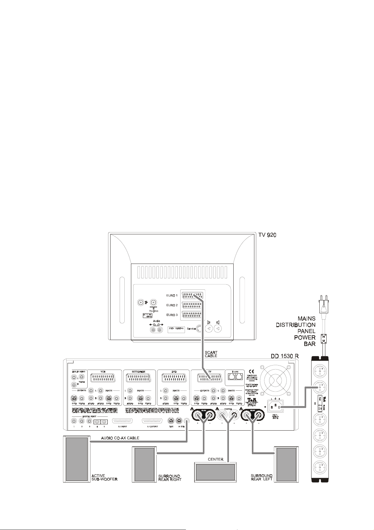
Connecting the digital surround decoder to a TV set and the surround loudspeakers
33
DD 1530 R
.
Page 34
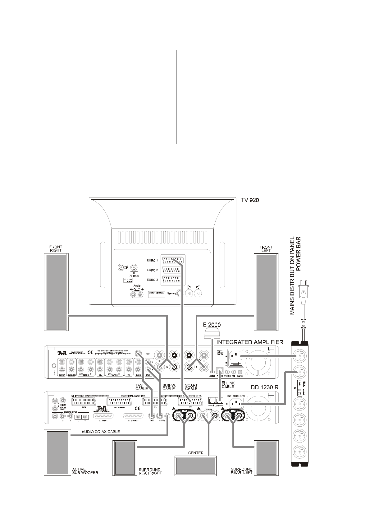
Connecting the decoder to a
with TASI and R
To keep the wiring diagram as clear as possible, only the
integrated amplifier is shown, i.e. not the analogue
source devices. The source devices should be connected as shown in wiring diagrams 6 . . 11. Complete
the wiring of the components as shown in wiring diagram
2 as follows:
• Connect the
TASI
socket on the
amplifier using the
• Connect the
R
LINK
socket on the integrated amplifier.
LINK
socket:
TASI
interface on the decoder to the
pre-amplifier or integrated
TASI
lead.
R
LINK
socket on the decoder to the
integrated amplifier
Wiring diagram 2
• If your system includes an active subwoofer, connect
the pre-amplifier output
SUB IN
Note:
If you are using a pre-amplifier with only one
output, and you have already connected the power
amplifier to this, you can use a
to gain access to the pre-amplifier signal. Please ask
your specialist
• Finally connect the mains power supply and switch
the system on.
on the decoder.
PRE
to the subwoofer input
Cinch Y-lead
dealer for advice.
PRE
adaptor
Connecting the
DD 1230 R
to a
integrated amplifier with TASI and
34
R
LINK
sockets.
Page 35
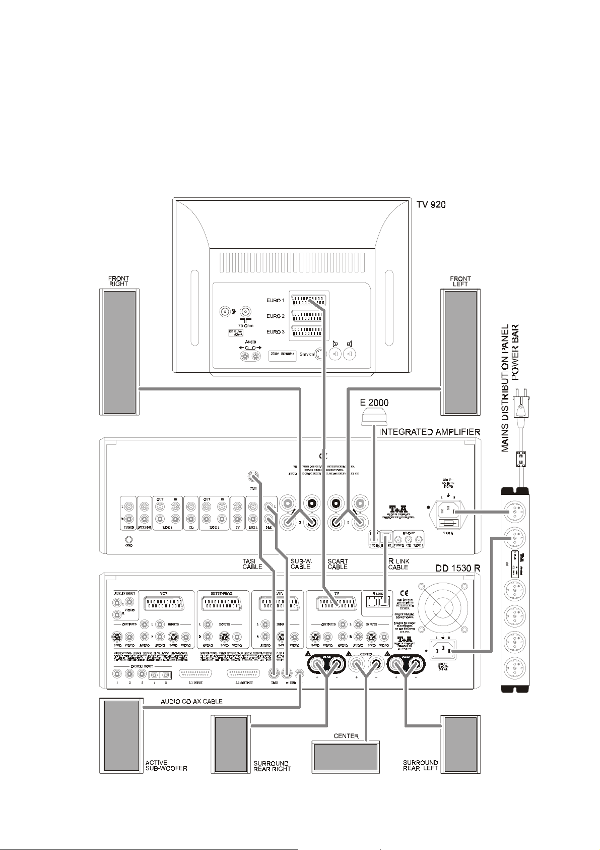
Connecting the
DD 1530 R
to a
integrated amplifier with TASI and
35
R
LINK
sockets.
Page 36

DVD player as digital sound and picture source
Connect the components as shown in wiring diagram
as follows:
• Connect the digital
DVD player to the digital input (
the decoder using a co-axial digital cable.
Note:
- Set the digital output of your DVD player to sur-
round mode!
- If the digital output of your DVD player is set to
'PCM'
, the player will only produce a digital stereo
signal. In this case the decoder cannot carry out
surround decoding.
• If you also wish to use the DVD player as a highquality CD player, connect its analogue output to the
pre-amplifier input CD or
source in the
SURROUND
'
Source Setup
sound output of the
DIGITAL INPUT 1
AUX 1
, and assign the
'
.
) of
Wiring diagram 3
3
• Connect the
DVD
the
Note:
If your DVD player does not feature a SCART socket,
use the VIDEO (Cinch) or S-VIDEO (Hosiden) and
AUDIO (Cinch) sockets on the decoder and the DVD
player.
• Connect the
R
LINK
by another source device, connect the lead to the va-
R
cant
• Finally connect the mains power supply and switch
the system on.
AV-OUT
socket on the decoder using a
R
socket on the decoder; if this is already in use
LINK
socket on the second source device.
socket of your DVD player to
LINK
socket on the DVD player to the
SCART
lead.
A DVD player connected to the
A DVD player connected to the
DD 1230 R.
DD 1530 R.
36
Page 37

CD player or CD mechanism:
Connect the components as shown in wiring diagram
as follows:
• Connect the digital sound output of the CD mechanism to the digital input (
decoder using a co-axial digital lead.
R
• Connect the
R
LINK
socket on the decoder; if this is already in use
by another source device, connect it to the vacant
R
LINK
socket on the second source device.
LINK
DIGITAL INPUT 2
socket on the CD player to the
) of the
Wiring diagram 4
4
• If you also wish to use the CD player as a high-quality
analogue stereo source, connect its analogue output
to a vacant input on the pre-amplifier and assign the
source in the
• Finally connect the mains power supply and switch
the system on.
Note:
The purpose of connecting a CD player or CD mechanism to the digital surround decoder is to play surroundencoded CDs, or to exploit the artificial sound fields
available in the decoder. CDs encoded with Dolby Surround and dts are available commercially.
'
Source Setup
'
.
A CD mechanism connected to the
A CD mechanism connected to the
DD 1230 R
DD 1530 R
.
.
37
Page 38

Digital SAT receiver (set-top box)
Connect the components as shown in wiring diagram
as follows:
• If the set-top box features an optical Dolby Digital
sound output, connect this to the digital input
DIGITAL INPUT 4
(
cable.
Note:
If your set-top box features a co-axial digital output, it
can be connected to one of the digital inputs
) of the decoder using an optical
1 . . . 3
Wiring diagram 5
5
• Connect the
SETTOPBOX
lead.
Note:
Any other video source device with digital sound can
also be connected to the SETTOPBOX input instead
of a set-top box.
If your set-top box does not feature a SCART socket,
.
use the VIDEO (Cinch) or S-VIDEO (Hosiden) and
AUDIO (Cinch) sockets on the decoder and the settop box.
• If you also wish to use the AV device as a high-quality
stereo source, connect its analogue output to a vacant input on the pre-amplifier and assign the source
in the
• Finally connect the mains power supply and switch
the system on.
SCART
socket on the decoder using a
'
Source Setup
socket on the set-top box to the
SCART
'.
A set-top box (digital sound and picture source) connected to the
A set-top box (digital sound and picture source) connected to the
DD 1230 R
DD 1530 R
.
.
38
Page 39

Analogue SAT receiver
Connect the components as shown in wiring diagram
as follows:
• Connect the
SETTOPBOX
the
SCART lead.
Note:
If your SAT receiver does not feature a SCART
socket, use the VIDEO (Cinch) or S-VIDEO (Hosiden)
and AUDIO (Cinch) sockets on the decoder and the
SAT receiver.
• If your set-top box does not feature a SCART socket,
use a SCART adaptor lead. Please ask your special-
ist
SCART
dealer for advice.
socket on the SAT receiver to
socket on the decoder using a
Wiring diagram 6
6
• Finally connect the mains power supply and switch
the system on.
Note:
Any other analogue source device can also be connected to the SETTOPBOX input instead of an analogue SAT receiver.
Analogue SAT receiver connected to the
Analogue SAT receiver connected to the
39
DD 1230 R
DD 1530 R
.
.
Page 40
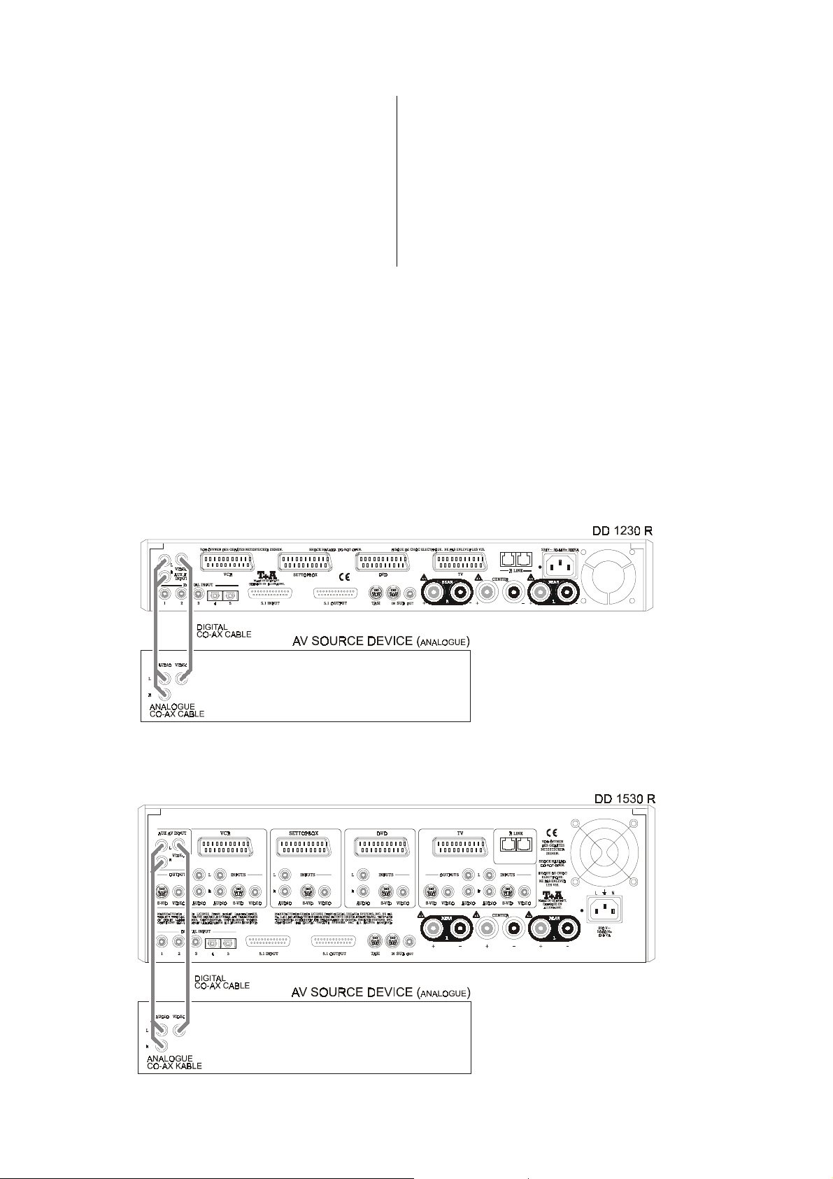
Analogue sound and picture source with co-axial audio and video outputs:
Connect the components as shown in wiring diagram
as follows:
• Connect the audio outputs L and R on the AV source
device to the L/R
coder.
• Connect the
VIDEO AUX-AV
to the
AUX-AV
VIDEO
input sockets on the de-
output on the AV source device
input socket on the decoder.
Wiring diagram 7
7
• If you also wish to use the AV device as a high-quality
stereo source, connect its analogue output to a vacant input on the pre-amplifier and assign the source
'
in the
Source Setup
• Finally connect the mains power supply and switch
the system on.
'
.
An analogue sound and picture source connected to the AUX-AV input of the
An analogue sound and picture source connected to the AUX-AV input of the
40
DD 1230 R
DD 1530 R
.
.
Page 41

Devices with recording and playback facilities (video recorder):
Connect the components as shown in wiring diagram
as follows:
• Connect the
VCR
the
Note:
If your video recorder does not feature a SCART
socket, use the VIDEO (Cinch) or S-VIDEO (Hosiden)
and AUDIO (Cinch) sockets on the decoder and the
video recorder.
SCART
socket on the decoder using a SCART lead.
socket on your video recorder to
Wiring diagram 8
8
• If you also wish to use the AV device as a high-quality
stereo source, connect its analogue output to a vacant input on the pre-amplifier and assign the source
'
in the
Source Setup
• Finally connect the mains power supply and switch
the system on.
'
.
An analogue device with recording and playback facilities (video recorder) connected to the
An analogue device with recording and playback facilities (video recorder) connected to the
DD 1230 R
DD 1530 R
.
.
41
Page 42

Variations on standard wiring
Special compatibility sets are available, to enable you to
combine the decoder with amplifiers and receivers from
earlier generations of
receivers of other makes, and also to use the unit in a
home cinema set-up.
To establish which compatibility set you require, please
check first whether your
TASI
a
interface (Cinch version: see illustration) or an
R
socket.
LINK
equipment, or with amplifiers /
amplifier / receiver features
4. The decoder in a home cinema set-up
The decoder can also be used for pure home cinema
applications without the addition of a stereo preamplifier or integrated amlifier. In this case a separate power amplifier (e.g.
quired for the front channels; see sketch.
A 1210
or
A 1520
is re-
TASI-interface
(Cinch version)
The following list provides information about the compatibility set you require.
1.
2.
amplifier (Cinch-version) and R
For this variant you need the compatibility set
amplifier with TASI interface (Cinch-version)
but without R
For this variant you need the compatibility set
LINK
socket.
LINK
-socket.
DKS 1
DKS 2
For this variant you need the compatibility set
5. Connecting the decoder to a different make of
amplifier / receiver.
If you are using a
decoder can be looped into the TAPE MONITOR circuit; see sketch.
.
For this variant you need the compatibility set
.
different make of amplifier
DKS 3
, the
DKS 4
.
.
3.
amplifier without TASI interface and without
R
socket.
LINK
If you have an amplifier of this type, we recommend
that you upgrade your system by purchasing a
R
amplifier with TASI- and
is possible to have certain models of
upgrade. Please ask your specialist
further details.
LINK
interface. However, it
dealer for
amplifier
6. Connecting the decoder to the PD 1200 R (analogue).
For this variant you need the compatibility set
-
Note:
Each compatibility set consists of the hardware you
require for the connections, together with instructions and information on connecting and setting up
the equipment.
42
DKS 5
.
Page 43

Optimising your system
Loudspeaker cables, inter-connects
Loudspeaker cables and signal leads (inter-connects)
have a significant influence on the overall reproduction
quality of your sound system, and their importance
should not be under-estimated. For this reason
recommends the use of high-quality cables and connectors.
Our accessory range includes a series of excellent cables and connectors whose properties are carefully
matched to our speakers and electronic units, and which
harmonise outstandingly well with them.
For difficult and cramped situations the
includes special-length cables and special-purpose connectors (e.g. right-angled versions) which can be used to
solve almost any problem concerning connections and
system location.
range also
Mains cables and mains filters
The mains power supply provides the energy which your
sound system equipment needs, but it also tends to carry
interference from remote devices such as radio and
computer systems.
Our accessory range includes the specially shielded
'POWER FOUR'
mains cable with integrated shell-type filters, and the
'POWER BAR'
vent electro-magnetic interference from entering your HiFi system.
The reproduction quality of our systems can often be
further improved by using these items.
If you have any questions regarding cabling please refer
to your specialist
comprehensive expert advice without obligation. We
would also be happy to send you our comprehensive
information pack on this subject.
mains cable, ready-to-use
mains filter distribution board which pre-
dealer, who will gladly give you
'POWER LINE'
Mechanical de-coupling
The base and surface on which your high-quality Hi-Fi
equipment is set up have an important influence on the
sound quality which the system can achieve.
The base should be as heavy, stable, hard and level as
possible. The decoder is supplied with newly developed
conical absorber feet. These feet have internal
damping characteristics, and de-couple the unit from the
base very effectively.
Note:
You can screw the
compensate for any slight unevenness in the base surface.
The unit must be adjusted to stand exactly horizontal in
every direction. All the feet must have a firm contact with
the base surface; the case must not wobble!
conical absorber feet in or out to
43
Page 44

Trouble-shooting
Many problems have a simple cause and a correspondingly simple solution. The following section describes a
few difficulties you may encounter, and the measures
you need to take to cure them.
If you find it impossible to solve a problem with the help
of these notes please disconnect the unit from the mains
and ask your authorised
vice.
specialist dealer for ad-
Restoring the works default settings
First display the software version number:
• Switch on the machine.
• Wait until the screen displays the loudspeaker sym-
bols.
• Hold the
(approx. 2 seconds).
• The software version number
sion number
the integral screen.
When the software version has been displayed, hold the
button on the front panel pressed in. The integral
screen now shows the message
screen displays the
Hold the
tion.
button on the front panel pressed in
'
'
and the DSP ver-
Vx-xx
Vx-xx
Vx-xxVx-xx
'
'
xxx
xxx
of the machine are now displayed on
xxxxxx
'
RESET
RESET aLL
RESETRESET
'
Service-Menu
button pressed in to accept the selec-
'
.
aLL
aLLaLL
'
, and the TV
Problem: Machine does not switch on (green LED
does not light up).
Cause:
Remedy:
Problem: Machine does not respond when buttons
Cause:
Remedy: Reset machine
Problem: The menu control system does not work.
Cause:
Remedy:
Problem: Machine responds correctly to manual
Cause 1:
Remedy:
Mains lead not plugged in correctly.
Check connections, push plugs in firmly.
are pressed.
Static discharge or powerful interference
(e.g. lightning) have corrupted the processor memory.
: disconnect mains plug,
wait about 10 seconds and re-connect.
Switch unit on again.
Master unit software is not designed for
decoder operation.
Software update required in master machine; ask your specialist
operation of the buttons, but does not
respond to remote control commands
via the “R”-series pre-amplifier, integrated amplifier or receiver.
Incorrectly inserted batteries or flat batteries
in the remote control handset.
Re-install batteries correctly or fit new ones.
dealer.
Cause 2: R
Remedy:
Cause 3:
Remedy:
Problem: Loud humming noise from the loud-
Cause:
Remedy:
LINK
or RC plug not fitted correctly in the
R
LINK
or RC socket on the decoder.
Complete the connections as shown in the
wiring diagram. Push in connectors firmly.
No visual contact between remote control
transmitter and remote control receiver
attached to the
integrated amplifier or receiver.
Ensure direct line-of-sight contact between
remote control transmitter and receiver.
Note that glass doors may prevent the
system working properly.
Maximum range between transmitter and
receiver approx. 8 metres.
Position the receiver in such a way that it is
not subjected to direct sunlight or strong
artificial lighting. Fluorescent and energysaving lamps are powerful sources of interference.
speakers.
Poor contact between the Cinch plugs and
sockets, or a faulty Cinch cable.
Please check all connections and cables
thoroughly.
'R'
-series pre-amplifier,
44
Page 45

Problem: No sound, or distorted sound.
Cause:
Remedy:
Problem: No sound from center, or center sound
Cause:
Remedy:
Problem: No sound from individual loudspeaker.
Cause 1:
Remedy:
Cause 2:
Remedy:
Cause 3:
Remedy:
Cause 4:
Remedy:
Cause 5:
Remedy:
Problem: No bass, or inadequate bass.
Cause 1:
Remedy:
Cause 2:
Remedy:
Problem: Subwoofer only works in surround
Cause:
Remedy:
Incorrect audio connection to amplifier or
TV set.
Check connections against wiring diagram;
push all connectors in firmly. Select a different listening source when checking the
amplifier.
signal too quiet.
Center speaker not connected, but activated in
Connect center loudspeaker, or disable
center speaker in
Loudspeaker not activated in
Setup
Call up
of loudspeaker connected.
Loudspeaker cable not connected correctly,
or short-circuit in speaker cable.
Check connection and speaker cable, correct if necessary.
Decoder not set to surround mode.
Call up
‘SURROUND’ or one of the sound fields.
Programme contains no information on the
auxiliary channels (e.g. stereo material).
If you wish, call up the
select a sound field.
The level for the channel affected is set too
low.
Call up
the level.
No subwoofer connected, but activated in
'
Speaker Setup
Connect subwoofer, or disable subwoofer in
'
Speaker Setup
Size of loudspeakers entered incorrectly in
'
Speaker Setup
Call up
settings match the loudspeakers in your
system; correct if necessary.
mode.
Subwoofer lead to stereo amplifier output
absent, or not correctly connected.
Connect subwoofer correctly, push connector in firmly.
'
Speaker Setup
'
.
'
Speaker Setup
'
Main Menu
'
Speaker Balance Setup
'
.
'
.
'
.
'
Speaker Setup
'
.
'
Speaker Setup
'
and enter the type
'
and set to
'
Main Menu
'
and check that
'.
'
Speaker
'
and
'
and raise
Problem: '
Cause:
Remedy:
Problem: The television set connected to the TV
Cause:
Remedy:
Problem: No picture from some or all source de-
Cause:
Remedy:
Problem: Neither on-screen menu nor other exter-
Cause 1:
Remedy:
Cause 2:
Remedy:
Problem: Picture unstable.
Cause:
Remedy:
Main Menu
sion screen.
Screen display of
in ‘Device Setup’.
Call up
screen Menu’.
output switches itself on, although a
source without an assigned video input
has been selected.
The TV set is responding to the AV switching voltage of the decoder‘s 'Slow blank
line'.
First display the software version number:
switch on the machine and wait until the
screen displays the loudspeaker symbols.
Hold the
pressed in (approx. 2 seconds). The soft-
ware version number
version number
now displayed on the integral screen.
Select
buttons. You can now use the
U
U
UU
wish to turn off the AV switch when using a
non-video source.
vices.
Source devices not supplying the switch
voltage which the TV set requires to switch
over to AV mode.
Set television to
mode.
nal programmes appear on the TV
screen. TV only shows those stations
which are received via its own aerial.
Video lead not connected properly.
Push in all connectors firmly.
The TV set does not switch automatically to
the AV input.
Set the TV set to
Synchronisation signal absent.
Push connector in firmly, or set television to
'AV operation'
' not displayed on the televi-
'
Main Menu
'
Device Setup
'
SLB
SLB ON
SLBSLB
buttons to switch to
button on the front panel
'
'
'
xxx
xxx
of the machine are
xxxxxx
'
using the
ON
ON ON
'constant AV operation'
'AV operation'
mode.
'
switched off
'
and switch on ‘on-
'
and the DSP
Vx-xx
Vx-xx
Vx-xxVx-xx
'
SLB
SLB OFF
SLBSLB
/
!
!
!!
T
T
TT
'
, if you
OFF
OFF OFF
mode.
/
45
Page 46

Problem: Monochrome picture only.
Cause:
Remedy:
Note:
Problem: Nothing on the decoder screen.
Cause:
Remedy:
Problem: The automatic format switch 4:3 / 16:9
Cause 1:
Remedy:
Cause 2:
Remedy:
Cause 3:
Remedy:
Problem: When playing an NTSC-DVD the on-
Cause:
Remedy:
Incompatible picture norms set on the TV,
the decoder and the source device.
Set TV, decoder and source device to the
same picture norm.
If problems persist, set the decoder to the
'RGB / Video'
'Video'
'Composite'
device.
The screen is switched off.
Switch the screen on again in the
'
Setup
does not work.
The TV set is not exploiting the switch voltage supplied through the SCART lead.
Switch TV set to
mode, or switch TV set manually.
The source device is not supplying the
requisite switch signals (e. g. the DVD
player when set to
Scan'
).
Switch TV set manually.
You are using the wrong cables. The switch
signals are only passed via SCART leads.
Use SCART leads.
screen menu is distorted.
The TV set does not feature automatic
format detection for NTSC, and has been
set manually to NTSC. The decoder’s onscreen menus are only generated in PAL
format, so this operation is not possible.
Use a TV set with automatic PAL / NTSC
format switching, or use the decoder’s integral screen.
norm; select the picture norm
, occasionally also termed
, on the TV set and the source
.
'controlled AV operation'
'Letterbox'
'FBAS'
'
Device
or
or
'Pan
Problem: Picture correct, but no sound audible
through the decoder.
Cause 1:
Remedy:
Cause 2:
Remedy:
Cause 3:
Remedy1:
Remedy2:
Problem: When you switch television pro-
Cause:
Remedy:
Note:
Problem: Decoder switches off after a certain
Cause:
Remedy:
No sound connection between source device and decoder.
Complete the sound connection (analogue
or digital depending on mode); see section
entitled
system for the first time
No sound input, or the wrong sound input,
has been assigned to the picture input in
the
Check the sound input to which the source
device is connected. Call up the
Setup
ment.
The loudspeaker is switched off.
Switch on the loudspeaker using the
j
j
jj
Check that the decoder has not switched
itself off due to overheating or a short-circuit
in the loudspeaker connection.
grammes, you hear unwanted noise.
The television set is not capable of muting
(silencing) the SCART audio outputs.
Connect the audio output (Cinch sockets)
on the TV set to the pre-amplifier’s
audio input. In the AUDIO column of the
'
Inputs Menu
instead of
This variant on standard wiring is possible
with all source devices for which a corresponding pre-amplifier input is available.
period of operation.
Unit is overheating.
Make sure that the cooling airflow is adequate; reduce volume if necessary.
'
Installation, wiring and using the
'
.
'
Source Setup
'
and carry out the correct assign-
button.
TASI
'
.
'
you must now select
!
'
Source
TV
TV
46
Page 47

Surround sound - explanatory notes
General information:
The following section is not concerned directly with the
operation of your digital surround decoder, but is rather
intended to explain some of the terms which arise in
connection with surround systems. It is intended to help
you understand and exploit the facilities and capabilities
of your decoder to the full.
As we all know, a normal stereo recording has two channels - left and right. When stereo material is reproduced
in your listening room, the entire sound event takes place
on an imaginary stage which covers the space between
the two loudspeakers. The listener is able to locate specific sound events over the width of the stage; with good
recordings there is also a slight impression of depth, i.e.
behind the speakers. Nevertheless, normal stereophonic
reproduction always leaves the listener isolated from the
event.
As a result it is impossible to recreate the excitement of a
live atmosphere, as in a real concert hall, since the
acoustics of the concert hall are crucially influenced by
sound reflections from the side and back walls, the floor,
the ceiling, and from objects inside the building. The
reflected sound comes from any number of directions not just from the front.
If a sound event is to be reproduced with real fidelity, it
therefore follows that a proportion of the sound must
emanate from all directions in the room, that the “reflections” must be timed accurately, and that they must be
generated at a realistic level.
Reproducing television sound via a conventional stereo
system is problematic, because it is often impossible to
locate dialogue on the screen itself.
A further point is that exotic sound effects have been in
use in the cinema since the 1950’s, using proper multichannel sound systems. These effects are often crucial
to the overall impact of a film, but they cannot be reproduced at home with a conventional stereo sound system.
Over the last few years surround technologies have been
developed which make it possible to experience all these
effects within the listener’s own four walls, with the result
that a far greater simulation of reality is possible than
with conventional stereo.
For an effective surround system we always recommend
the installation of a center loudspeaker, which is installed
below or directly above the TV set. This loudspeaker
helps greatly in locating particular sound events (especially dialogue) on the TV screen itself.
Dolby Pro Logic II Surround
In this process serveral independent signal channels
(left, center, right, surround (rear) left and surround (rear)
right) are recorded using two channels and a special
encoding process. Since this process only requires two
recording channels, it is compatible with many picture /
sound systems which are already widely in use (CD,
video recorder, TV etc.).
The information is decoded at playback time and reproduced in the listening room via four (left, right, 2 x rear)
loudspeakers, although five speakers (with an additional
front center speaker) are preferable. Dolby Surround
encoded material is currently available mainly in the film
and video arena, recorded on video cassettes and DVDs,
but a large number of television programmes are now
being produced and transmitted using Dolby Surround.
47
Page 48

Dolby Digital
Dolby Digital is a digital multi-channel surround system
which was developed specifically for spatial sound reproduction in connection with 35 mm cinema films. The
process utilises five separate sound channels: three front
channels (left, center, right) and two surround channels.
A sixth independent bass effect channel is also present,
5.1
channels.
LFE
). That is why
catering for low frequency effects (
such systems are said to offer
In comparison with Dolby Pro Logic II, Dolby Digital provides two independent surround channels which provide
genuine spatial stereo sound, offering the same realistic
stereo reproduction as provided by the front channels.
The decoder’s integral Dolby Digital decoder provides
the means of obtaining a genuine digital Dolby stereo
cinema presentation in your own living room. The discrete digital recording process and the five playback
channels guarantee a very wide dynamic range and
accurate spatial orientation.
Sound field simulation
The surround processes already described require programme material which is encoded using the appropriate
system, but the digital surround decoder also offers a
facility to enhance the spatial effect available with conventional unencoded stereo recordings (CD, MC, VHF
radio etc.).
This it does by offering a range of artificial
simulations
These sound fields are based on a precise analysis of
the acoustics found in typical concert halls.
The digital signal processor of your digital surround decoder is capable of simulating the spatial sound of these
halls, and reproducing it via the five channels of your
surround system.
For example, if you select the
watching a rock concert on television, you will have the
illusion of sitting in the middle of the audience.
Please note that it is important to set the sound field
which is appropriate to the material to which you are
currently listening. It makes no sense at all to select a
sports stadium if you intend listening to a concert of
chamber music, or an intimate club atmosphere for a
rock concert.
Your digital surround decoder can generate the following
sound fields:
, including theatre, stadium, club etc.
HALL
sound field
setting while
dts Digital Surround
dts
The “
developed to replace analogue film soundtracks, using
digital soundtracks consisting of six discrete channels.
This system has now been further developed to provide
spatial sound reproduction in the home situation.
The six channels (
quality, i.e. with 20-bit resolution, and recorded using
only slight data compression. The 5.1 loudspeaker configuration, currently the standard arrangement for home
cinema systems, is ideal for playback.
” multi-channel film sound system was originally
5.1
) are encoded / decoded in original
HALL
THEATRE
STADIUM
CLUB
CHURCH
DISCO
48
Page 49

The
surround system
Multi-channel reproduction based on surround technology does indeed open up new worlds of experience, but
the technical implementation of a multi-channel surround
system does involve a number of potential pitfalls. Many
existing surround systems have gained a reputation for
no more than moderate sound quality, especially when
used in normal stereo mode.
The reason for this lies in the tiny magnitude of the sensitive analogue stereo signals. These signals are measured in the range of just a few Millivolts (thousandths of a
Volt), and unwanted interference to these signals can be
perceived by the human ear even when a thousand
times smaller than that. Conventional surround amplifiers
feature a single case in which digital signals and highfrequency video signals live in the same space as the
sensitive analogue signals, and this represents an open
invitation for interference between the various signals.
This compromise solution is entirely unacceptable to us
at
, so for our surround system we developed an
arrangement in which the various signal processing
sections were kept entirely apart. The system therefore
comprises two specialised devices: an analogue twochannel stereo amplifier is used to process high-quality
stereo signals, while the digital surround signals are
processed in the surround decoder which is an independent machine.
In the
assemblies are separated from each other completely,
and this eliminates the danger of interference to the
delicate analogue signals. The net result is that there is
absolutely no danger of a loss in quality in analogue
stereo reproduction.
To make it possible to integrate the surround decoder
easily into an existing
means to process and reproduce analogue signals, e.g.
Dolby Surround encoded source material.
This interface is the key to integrating the decoder elegantly into the overall system. At the same time the decoder has absolutely no effect on normal stereo signals,
since it is completely removed from the signal path during normal stereo operations.
Not even the length of the signal paths is changed; in
stereo mode all signals remain in the pre-amplifier section of the amplifier, i.e. they are not forced to make a
detour through the surround decoder.
system the analogue and digital sub-
system, we developed the
surround interface (TASI), which also provides the
When the system is used in Pro Logic II mode, the TASI
interface also ensures that the decoder is looped in at
the ideal point and at the optimum level in terms of signal
processing, i.e. directly after the source selector switch.
An additional advantage of the TASI interface is that it
makes it possible to exploit the superb output stages of a
typical
surround mode.
To ensure that the sound from the whole system is as
balanced and harmonious as possible, the output stages
built into the decoder are identical in circuit design to our
stereo output stages. This design philosophy ensures
identical frequency, phase and transient behaviour on all
channels, combined with perfectly balanced dynamic
characteristics.
The
vantages: two separate pre-amplifier circuits are present,
each with its own volume and tone control functions: a
stereo pre-amplifier and an independent six-channel preamplifier in the surround decoder.
It is therefore possible to adjust the levels and tone settings separately to meet the different requirements for
stereo and surround modes. When you switch mode, the
correct settings automatically take effect.
stereo system for the front channels when in
surround philosophy also provides further ad-
49
Page 50

Glossary
AV source device
A source device which supplies sound and picture signals. The sound signals may be generated in analogue
or digital form.
Center
Front loudspeaker between the two main speakers, located below or directly adjacent to the TV set.
dB
The unit of measurement for electrical levels is the deci-
B
el (dB).
DSP (D
The digital surround decoder employs a fully programmable signal processor. A DSP can process signals
using a program stored in the program memory. The
program can be updated at any time, which means that
the decoder can be kept abreast of new developments.
igitaler Signal Processor)
Front-speaker
Front pair of main loudspeakers, set up to left and right
of the television set.
STANDBY
The digital surround decoder can be switched on from
stand-by mode at any time by pressing a button on the
remote control handset.
Subwoofer
Loudspeaker designed for reproducing low bass signals.
It is used for special deep bass effects which are encoded on the LFE channel in Dolby Digital and dts material. When combined with small satellite speakers they
also provide a full-range bass response.
S-VIDEO
High-quality picture norm with separate brightness and
colour signals. Better picture quality than standard video.
However, as the colours are not transmitted separately,
picture quality is not quite as good as with the RGB
method.
TASI
This standard
surround decoder between the source selector
switch and the volume control of the stereo amplifier. The
interface automatically detects the decoder when it is
connected. In surround mode the volume and tone controls of the stereo amplifier are disabled, as these functions are assumed by the decoder.
interface makes it possible to loop a
Surround-speaker
Rear pair of loudspeakers, set up behind the listening
position, designed to provide spatial sound effects.
LINK
R
Universal control interface by means of which all the
components of a
that they are fitted with an
system communicate, provided
R
LINK
control socket.
RGB
High-quality picture norm, utilising separate wires for the
colour signals
problem of signal contamination;
vides the best possible picture quality.
red, green
and
blue
. This avoids the
RGB playback pro-
SCART
Widely used standardised connection using a 21-pin
connector. SCART leads can transfer all picture norms
and additional control signals (e.g. for 3:4 / 16:9 picture
format switching). Adaptors are available in specialist
shops for connecting a SCART socket to other standard
connectors (Cinch or Hosiden).
Update
Method of bringing the software used by the decoder’s
main processor or signal processor abreast of new developments. Updating the software provides for future
expansion of functions and changes to meet new requirements.
VIDEO
Standard picture norm: colour and brightness information
is transmitted by a single conductor. Standard video
connections are present on all AV devices.
50
Page 51

Specification
Decoder
Analogue inputs:
Digital inputs
(3 x co-axial, 2 x optical):
A/D converter:
D/A converter:
Analogue filter:
Decoder type:
Frequency response:
Total harmonic distortion:
Signal : noise ratio (A-weighted):
Signal : noise ratio (unweighted):
Effective system dynamic range:
Channel separation:
Volume control:
Tone controls:
Operating modes:
DD 1230 R
500mV / 20 kΩ
5 x SP/DIF, 44.1 kHz, 48 kHz and 96 kHz
2 channel, 24 bit, 48 kHz
6 channel, 24 bit, 192 kHz
3rd order, 60 kHz, Bessel
56-bit signal processors
1 Hz . . . 22 kHz
< 0.004 %
> 106 dB
> 103 dB
> 94 dB
> 100 dB
analogue, 1,5 dB increments
fully digital, channel-separate
Dolby Digital, Dolby ProLogic II, dts Digital Surround
Sound fields: Stadium, Club, Hall, Theatre, Church, Disco
DD 1530 R
Output stage
Nominal power per channel *
Peak power per channel *
* Power specification: both channels driven simultaneously
= 240 V (230 V version) or 120 V (115 V version)
U
main s
Power bandwidth:
Frequency response +0 -3dB:
Slew rate:
Damping factor:
Signal : noise ratio (A-weighted):
Total harmonic distortion:
into 8
into 4
into 8
into 4
:
ΩΩΩΩ
:
ΩΩΩΩ
:
ΩΩΩΩ
:
ΩΩΩΩ
General
Mains power:
Power consumption:
Standard accessories:
Optional accessories and
expansion units:
80 Watts 150 Watts
100 Watts 200 Watts
160 Watts 200 Watts
200 Watts 250 Watts
1 Hz . . 300 kHz
1 Hz . . 400 kHz
60 V/µs
> 500
> 110 dB
< 0.002 %
see print on the back panel
300 VA 600 VA
Mains lead, SCART lead, TASI lead,
subwoofer lead,
operating instructions, guarantee certificate
Interconnect and loudspeaker cables, connectors,
rack systems, matching design
R
LINK
lead,
We reserve the right to alter specifications.
51
Page 52

elektroakustik GmbH & Co. KG
Herford
Germany
 Loading...