


T2240-24
T2240/9
Operator’s Manual Matrix Printer
Bedienungsanleitung Matrixdrucker
Manuel d’utilisation Imprimante matricielle
Istruzioni per l’uso Stampante a Matrice
Instrucciones de servicio Impresora matricial
T2240/24
T2340/9
T2340/24
Important Information
This equipment generates and uses radio frequency energy and if not
installed and used properly, that is, in accordance with the manufacturer’s
instructions, may cause interference in radio and television reception. It
has been type tested and found to comply with the limits for class B
computing devices in accordance with the specification in subpart J of part
15 of FCC rules, which are designed to provide reasonable protection
against such interference in a residential installation. However, there is no
guarantee that interference will not occur in a partial installation. If this
equipment does cause interference to radio or television reception, which
can be determined by turning the equipment off and on, the user is
encouraged to try to correct the interference by one or more of the following
measures:
Reorient the receiving antenna,
Relocate the peripheral away from the receiver,
Move the peripheral away from the receiver
Plug the peripheral into a different outlet, so that the peripheral and
receiver are on different branch circuits
If necessary, the user should consult the dealer or an experienced
radio/television technician for additional suggestions. The user may find
the following booklet, prepared by the Federal Communications Commission, helpful: “How to Identify and Resolve Radio-TV Interference
Problems”.
This booklet is available from the U.S. Government Printing Office, Washington DC 20402 Stock No. 004.000.00345.4.
WARNING:
ference for a class B computing device, the printer cable must be shielded.
To assure compliance with FCC regulations for a computing device, use
a shielded interface cable with a metal shell connector. The use of cables
not properly shielded may result in violating FCC regulations.
This digital apparatus does not exceed the class B limits for radio noise
emissions from digital apparatus as set out in the radio interference
regulations of the Canadian department of communications.
This unit complies with DOC standard C108.8-M 1983
ATTENTION: Le présent appareil numérique n’ement pas de bruits
radioélectriques déspassant les limites applicables aux appareils
numériques de la classe B prescrites dans le règlement sur le brouillage
radio- électrique édicté par le minstère des communications du Canada.
To comply with FCC regulations on electromagnetic inter-
The paper used is made of raw materials treated with a chlorine-free
bleaching process.
Das verwendete Papier ist aus chlorfrei gebleichten Rohstoffen
hergestellt.
Le papier utilisé est fabriqué à partir de matières premières blanchis sans
chlore.
La carta utilizzata è prodotta con materiali sbiancati senza cloro.
El papel utilizado ha sido fabricado con un proceso de blanqueo libre de
cloro.
This device fulfils the European standards requirements by complying with the Directive of the Commission
dated May 3, 1989 (89/336/EEC) relating to electromagnetic compatibility and the Directive dated February 19,
is indicated by the CE symbol attached to the device.
1973 (73/23/EEC) relating to low-voltage electrical equipment. Conformity with the above mentioned Directives
Note: Conformity may be affected by:
using interface cables not complying with the specifications
non-observance of important instructions in the operator’s manual
installing components not approved for this device by the manufacturer
unauthorized manipulation
Dieses Gerät erfüllt die Anforderungen der Europäischen Normen durch Einhaltung der Richtlinie des Rates
vom 3. Mai 1989 (89/336/EWG) bezüglich der Elektromagnetischen Verträglichkeit sowie die Richtlinie vom 19.
den oben angeführten Richtlinien ist durch das am Gerät angebrachte CE-Zeichen gekennzeichnet.
Februar 1973 (73/23/EWG) bezüglich Elektrischer Betriebsmittel mit Niederspannungen. Die Konformität zu
Hinweis: Die Konformität kann beeinflußt werden durch:
Benutzung von nicht spezifizierten Schnittstellenkabeln
Nichtbeachtung wichtiger Hinweise der Bedienungsanleitung
Ersetzen von Bauteilen, die nicht vom Hersteller für dieses Gerät freigegeben wurden
Eingriffe durch Unbefugte
Cet appareil remplit aux exigences des normes européennes en respectant la directive du Conseil du 3 mai
1989 (89/336/CE) relative à la compatibilité électromagnétique et la directive du 19février 1973 (73/23/CE) en
marque de conformité de la Communauté Européenne (CE).
matière du matériel à basse tension. La conformité aux directives mentionnées ci-dessus est repérée par la
Remarque: La conformité peut être influencée par:
l’utilisation de câbles d’interface non spécifiés
le non-respect de consignes importantes du manuel d’utilisation
le remplacement de composants qui n’ont pas été homologués pour cet appareil par le constructeur
l’intervention de personnes non autorisées
Questo apparecchio soddisfa le richieste delle norme europee rispettando la direttiva del consiglio del 3 Maggio
1989 (89/336/CEE) relativa alla compatibilità elettromagnetica nonché la direttiva del 19 Febbraio 1973
è contrassegnata con il simbolo CE applicato sull’apparecchio.
(73/23/CEE) relativa a mezzi di produzione elettrici a bassa tensione. La conformità alle direttive sopra citate
Nota: La conformità può essere influenzata tramite:
Utilizzo di cavi interfaccia non specificati
Inosservanza di importanti indicazioni delle istruzioni per l’uso
Sostituzione di componenti per i quali non è stato dato il benestare dal produttore per questo apparecchio
Interventi tramite persone non autorizzate
Este equipo corresponde a lo exigido en las normas europeas a base del cumplimiento de la directriz del Consejo
del 3 de mayo de 1989 (89/336/CEE) en lo que se refiere a la compatibilidad electromagnética así como de la
tensiones. Para señalizar la confor
Indicación:
directriz del 19 de febrero de 1973 (73/23/CEE) en lo que se refiere a los materiales eléctricos con bajas
La conformidad puede estar influida por:
la utilización de cables de interface no especificados
midad con las directrices antes mencionadas, el equipo está dotado de la marca CE.
la inobservancia de indicaciones importantes contenidas en el manual de servicio
la sustitución por componentes, que no han sido homologados por el fabricante para el equipo en cuestión
intervenciones de personas no autorizadas
WARNING Only trained and qualified personnel may open covers or remove parts that are not explicitly shown and described in the User Guide as being accessible to
the operator.
WARNUNG Das Entfernen oder Öffnen von Abdeckungen und Teilen darf nur durch geschultes Fachpersonal vorgenommen werden. Ausgenommen hiervon sind nur
solche Abdeckungen und Teile, deren Entfernen bzw. Öffnen in der Bedienungsanleitung ausdrücklich gekennzeichnet und beschrieben sind.
ATTENTION Seul un personnel qualifié et formé est habilité à démonter les sous-ensembles de la machine qui ne sont pas formellement indiqués dans le Manuel
d’utilisation meme s’ils sont accessibles par l’opérateur.
ATTENZIONE Solo personale qualificato puo’accedere a parti che non siano esplicitamente descritte nelle Istruzioni per l’operatore come accessibill all’operatore.
ADVERTENCIA Las cubiertas y piezas sólo deberán ser quitadas o abiertas por personal especializado. Se exceptúan de esta regla sólo las cubiertas y piezas cuya
retirada y apertura estén indicadas y descritas expresamente en las Instrucciones de uso.

Quick start-up
Table of contents
Operator’s Manual
QUICK START-UP
Introduction 2
Symbols used in this manual 2
Important safety instructions 2
Using the online documentation 2
Troubleshooting 2
The printer at a glance 3
Installation 5
Unpacking the printer 5
Positioning your printer 5
Connecting the printer 6
Switching the printer on and off 6
Control panel 7
Online mode 7
Offline mode 7
Setup mode 7
Installing the ribbon cassette 8
Loading paper 10
Cut Sheet paper 10
Printer in fanfold paper mode 12
Changing the paper type 14
Paper path quick selection 14
Paper transport 15
Using 15
Moving paper to the tear position 15
Settings (I) 16
Setting the tear position 16
Setting the first printing line (TOF) 16
Settings (II) 18
Setting the print head gap 18
Changing paper in Setup mode 19
From fanfold paper to single sheet mode 19
From single sheet to fanfold paper mode 20
Selecting a font 21
Setting the character pitch 22
Specifications 23
Printer specifications 23
Paper specifications 23
Accessories 24
ENGLISH
1
Introduction Quickstart-up
Introduction ThisOperator’sManualisintendedasaquickintroductionintoworkingwiththeprinterandis
Ah ha!
➤Symbolsusedinthis
manual
STOP
➤Importantsafety
instructions
STOP
toenablealsounexperienceduserstohandlethedeviceproperly.Itdescribesthemostimportant
functionsoftheprinterandcontainstheessentialinformationforyoureverydayworkwiththe
printer.Amoredetaileddescriptionoftheprinter,itscharacteristicfeaturesandfurtherinformationiscontainedinthereference manual ontheonline CD-ROMwhichisincludedattheback
of thismanual.
Importantinformationishighlightedinthismanualbytwosymbols.
CAUTIONmarksinformationwhichmustbeobservedinordertopreventinjuriestotheuser
anddamagetotheprinter.
NOTEmarksgeneraloradditionalinformationaboutaspecifictopic
Readthefollowinginstructionscarefullybeforeputtingtheprinterintooperationinorderto
protectyourselffrominjuryandavoiddamagetotheprinter.
KeepthisOperator’sManualalwaysreadilyaccessible.
Placetheprinteronastablesurfacesothatitcannotfalldowntotheground.
Avoidexposingtheprintertohightemperatureordirectsunlight.
Keepallliquidsawayfromtheprinter.
Donotexposetheprintertoshock,impactorvibration.
Neverswitchontheprinterwhenitisnotsettothecorrectvoltage.
Nevertrytocarryoutmaintenanceandrepairworkyourself;alwayscallaqualifiedservice
technician.
STOP
➤Usingtheonline
documentation
Whenyouwanttodisconnecttheprinterfromthemainspowersupply,alwayspulloutthe
mainsplugfromthewalloutlet.
Youwillfindadditionalsafetyinformationatspecificplacesinthetext.
FirstinstalltheAdobeAcrobatReaderonyourharddiskunlesstheprogramhasalreadybeen
installed.Toinstallit,followthestepsdescribedintheREADMEfileintheREADERdirectory.
Tostarttheonlinedocumentation,calltheFileManager(Windows3.1)orExplorer(Windows95/Windows98/WindowsNT)anddoubleclickontheSTART.PDFfile.Thenfollowthe
instructionsandmenusonthescreen.
IfyourCD-ROMshouldbedefectiveormissing,pleaseconsultyourdealer.
Theonlinedocumentationisalsoavailableasaprintedmanual(forasmallfee)andviathe
internet.
Minimumhardwarerequirements:PCAT486,4xCD-ROM,15"monitor,mouse.
➤Troubleshooting TheonlinedocumentationsuppliedontheCD-ROMcontainsdetailedinformationontrouble-
shooting.
2
Quick start-up The printer at a glance
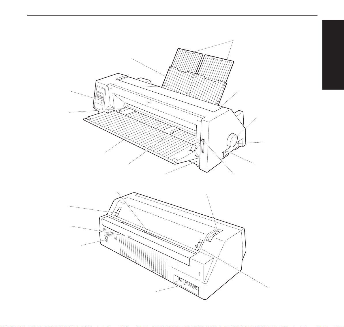
The printer at a
glance
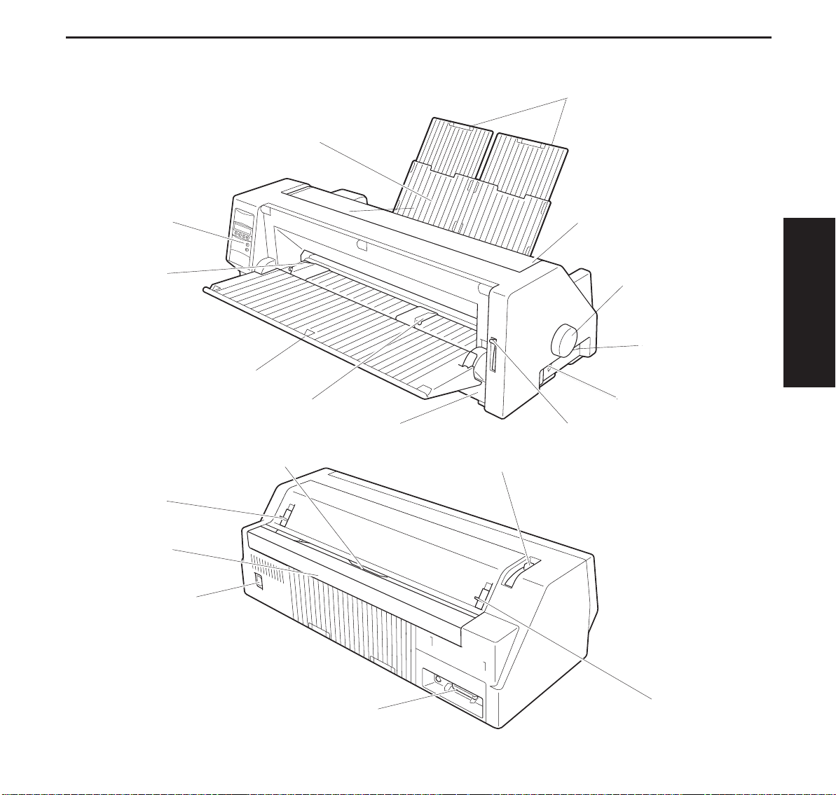
Operation Panel
Left Paper Guide
Cut Sheet Paper Insert Guide
Perforated Line Cutter
The following figures show the name of each printer part, and the table on the following page
shows the functions of each part.
Paper Tray
Right Paper Guide
Front Cover
Paper Thickness Adjustment Lever
Paper Extension Trays
Access Cover
Paper Feed Knob
Power Switch
Option Connectors
Paper Type Selection Lever
ENGLISH
Latch Lever
Rear Covere
Power Inlet
Interface Connector
Latch Lever
3
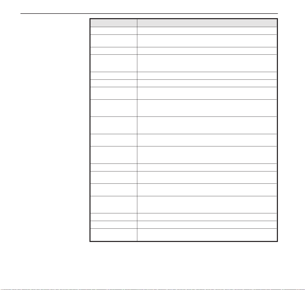
The printer at a glance Quick start-up
Name Functions
Operation Panel It indicates the printer status, and is used to change various settings.
Paper Tray It is used as a paper support for cut sheet paper already printed when the
Paper Extension Trays They are used for extendingof the Paper Tray.
Access Cover When the Ink-ribbon Cartridgeis to be replaced or paper jams are to be
Paper Feed Knob It is used to manually feed paper forwardor backward.
Power Switch It is used to turn ON or OFF the power of the printer.
Option Connector It is used to connect an Auto Sheet Feeder(ASF) or the Optional 2nd
Paper Type Selection
Lever
Front Cover It is opened when Continuous Form Feed Paperis to be set. This cover is
Right Paper Guide By aligning the right edge of the Cut SheetPaper to this guide, an uneven
Cut Sheet Paper Insert
Guide
Left Paper Guide It is used to adjust the left margin of the Cut Sheet Paper.
Latch Lever By pulling this lever to the front, the latch is released and the Access
Perforated Line Cutter ContinuousForm Feed Paper will be cut at this position. By pressingthe
Paper ThicknessAdjustment Lever
Interface Connector It is used to connect the I/O cable to the system unit.
Power Inlet It connectsto the power cord.
Rear Cover It is used to reduce noise. It must be removedwhen the paper tray is in
option “F-Eject” is set to OFF in the Initial Setting.
removed, this cover is detached to allow access to the related parts. It also
serves to protect operators from the mechanical movements of the printer.
Tractor.
It is used to select the appropriate type of paper to be used in the printer:
Cut Sheet Paper (upper position)
Continuous Form Feed Paper (lowerposition)
detached when an Auto Sheet Feeder (ASF)or the Optional 2nd Tractor is
to be attached.
feed can be prevented.
It is opened for inserting Cut Sheet Paper and is used as a paper support.
It is also used as a support for post-printCut Sheet Paper when the option
“F-Eject” is set to ASF,Single or ALL in the Initial Setting.
Cover can be opened.
Tear key after printing,paper feeds up to this position.
It is used to adjust the paper-pinching strength of the printer in accordance
with the thickness of the paper to be used. As for the adjustment ranges,
see
Paper Thickness Adjustment
upright position.
, page 18.
4
Quick start-up Installation
Installation
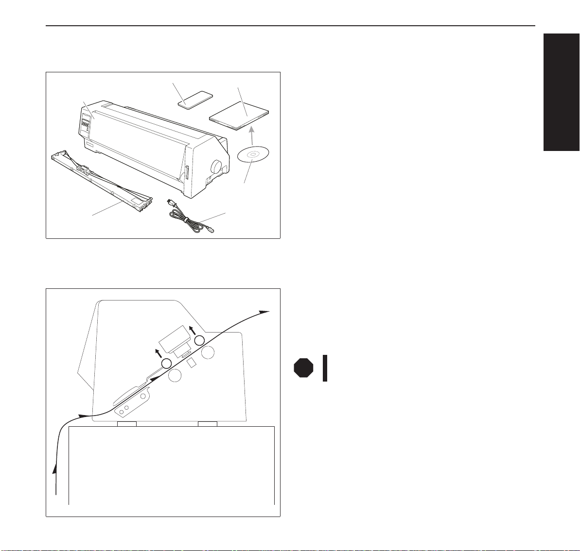
➤Unpacking the printer Please open the printer package and check that all the following items are included.
Unpacking Instructions
Printer
Ink-ribbon
➤Positioning your
printer
Operator’s Manual
CD-ROM
Power Cord
Place the printer on a stable, flat and non-slip surface in such a way that it cannot fall down.
Ensure easy access to the control panel and the paper feeders and leave sufficient space for the
paper ejected.
Ifany itemismissingordamaged, pleasecontactthe storewhere
the product was purchased.
Remove the transport protection elements as described in the
unpacking instructions.
The carton and the packing materials will be necessary for
moving or transporting the printer. Please store them in a safe
place.
If frequent forward and return feed movements will be performed with fanfold paper, you should position the printer as
illustrated in the figure.
Whenchoosingasuitableplacefor yourprinter, youshouldalso
observe the following:
ENGLISH
STOP
■ Avoid exposing the printer to direct sunlight. If you cannot
avoid placing the unit near a window, protect it from sunlight
with a curtain.
■ Position the printer near the computer to which it will be
connected. The distance must not exceed 2 m.
■ Ensure sufficient distance from radiators.
■ Ensure that the printer is not exposed to extreme variations
in temperature or air humidity. Avoid exposure to dust.
Never place the printer near sources of easily inflammable gas or explosive substances.
5
Installation Quick start-up
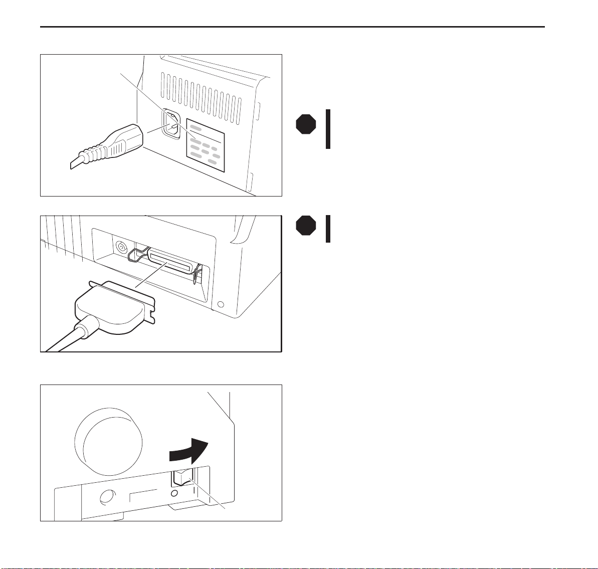
➤ Connecting the printer
Make sure that the unit is set to the correct voltage (i.e. 230 V
Type Plate
for Europe, 120 V for the USA). Refer to the type plate beside
the power inlet on the rear side of the printer.
If this is not the case, contact your dealer.
➤ Switching the printer on and off
STOP
Never switch on the printer when it is not set to the
correct voltage since this could cause severe damage.
Connect the power cable to the printer’s power
inlet as shown in the figure.
Connect the power cable plug to a wall outlet.
STOP
Make sure that the printer and the computer are
switched off.
Connect the printer-end connector of the data
cable to the female interface connector and secure it with the
spring clips.
Connect the other end of the cable to the computer.
The power switch, which is used for switching the printer on
and off, is located at the right side of the printer.
Power Switch
6
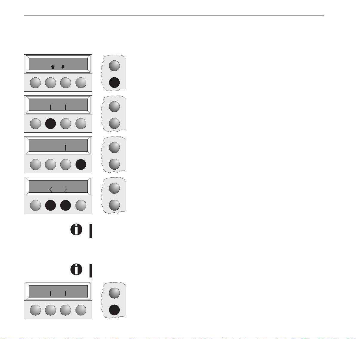
Quickstart-up Controlpanel
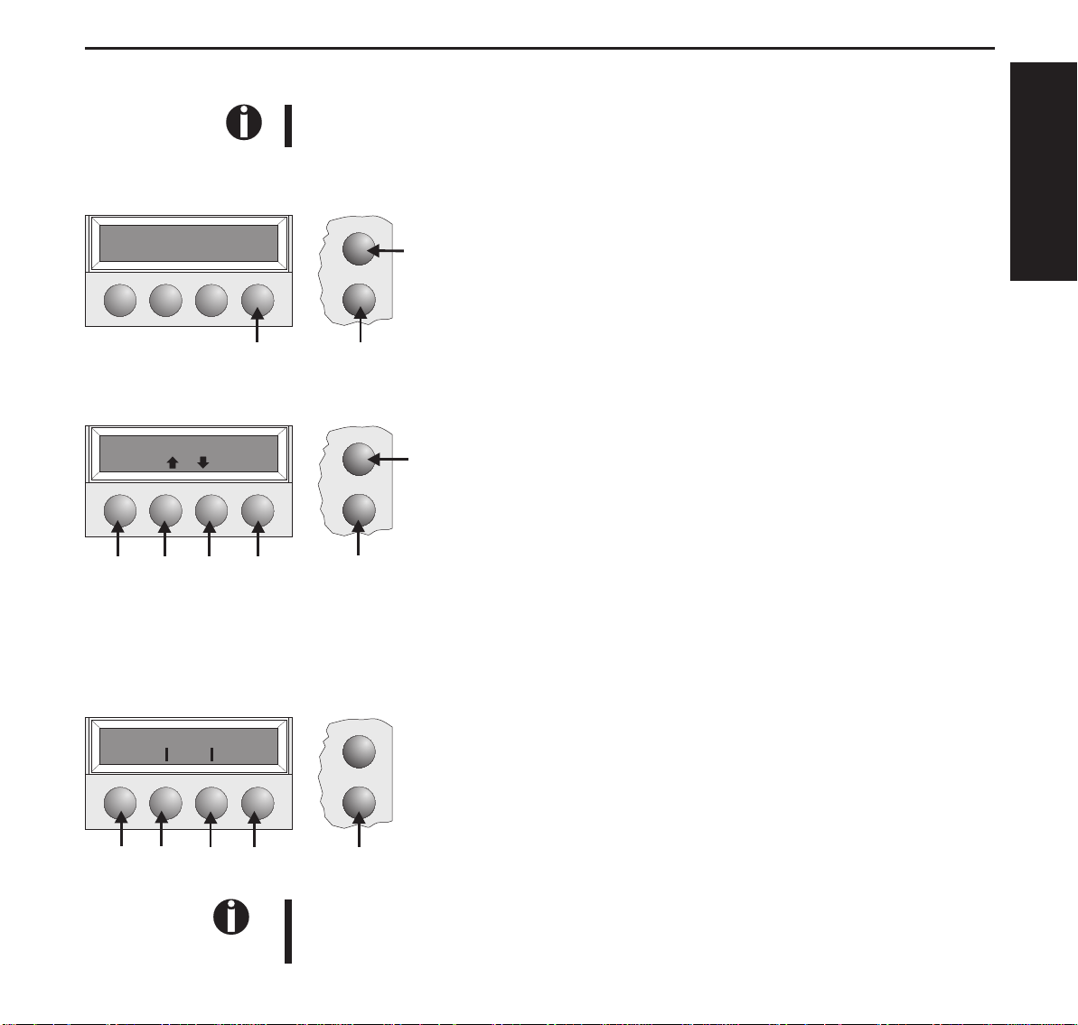
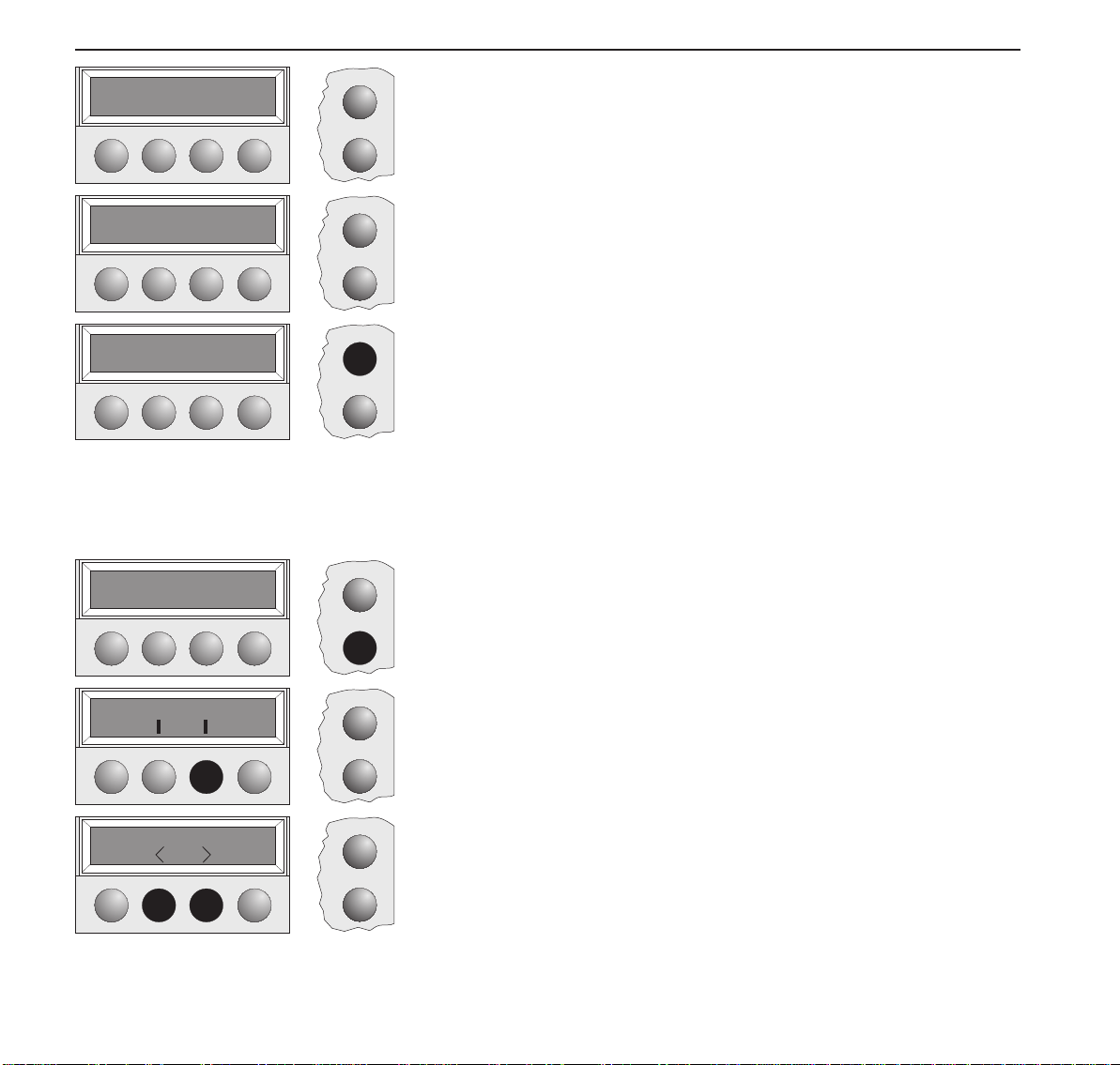
Controlpanel Youcancontrolprinteroperationusingthecontrolpanelandthekeys.
ThefirstlineofthedisplayinformsyouaboutwhethertheprinterisinOnlineorinOffline
modeandaboutthepaperpathselected(Trac.1orSingle).
➤Onlinemode Whenswitchingontheprinter,itautomaticallyselectsOnlinemode.Itcanreceivedatafromthe
computeronlyinthismode.
Online Trac.1
Tear
Online
Setup
➀SetstheprintertoOfflinemode.
➁SetstheprintertoSetupmode.
➀
➂Tearkey:Activatesthetearfunctionwhenfanfoldpaperisloaded
(seepage15).IfLoadisdisplayedabovethiskey,nopaperisloadedin
theprinter;pressthekeytofeedpapertotheprintingposition.
ENGLISH
➂
➁
➤Offlinemode Stepfeeds,linefeedsandformfeedscanbeperformedviathecontrolpanelonlyinthismode
(seepage15).
Offline Trac.1
Park LF/FF
Online
Setup
➀SetstheprintertoOfflinemode.
➁SetstheprintertoSetupmode.
➀
➂Ifnopaperisloaded:Loadkey(seeabove).Ifpaperisloaded:
Shortkeypress:Linefeed(LF)
Longkeypress:Formfeed(FF)
➃Shortkeypress:Micro-stepreturn
➄➅
➂➃
➁
Longkeypress:Constantpaperfeedreturn
➄Shortkeypress:Micro-stepforward
Longkeypress:Constantpaperfeedforward
➅Clearsthepaperpathwithpaperloadedandactivatespaperpathquick
selection(seepage14).
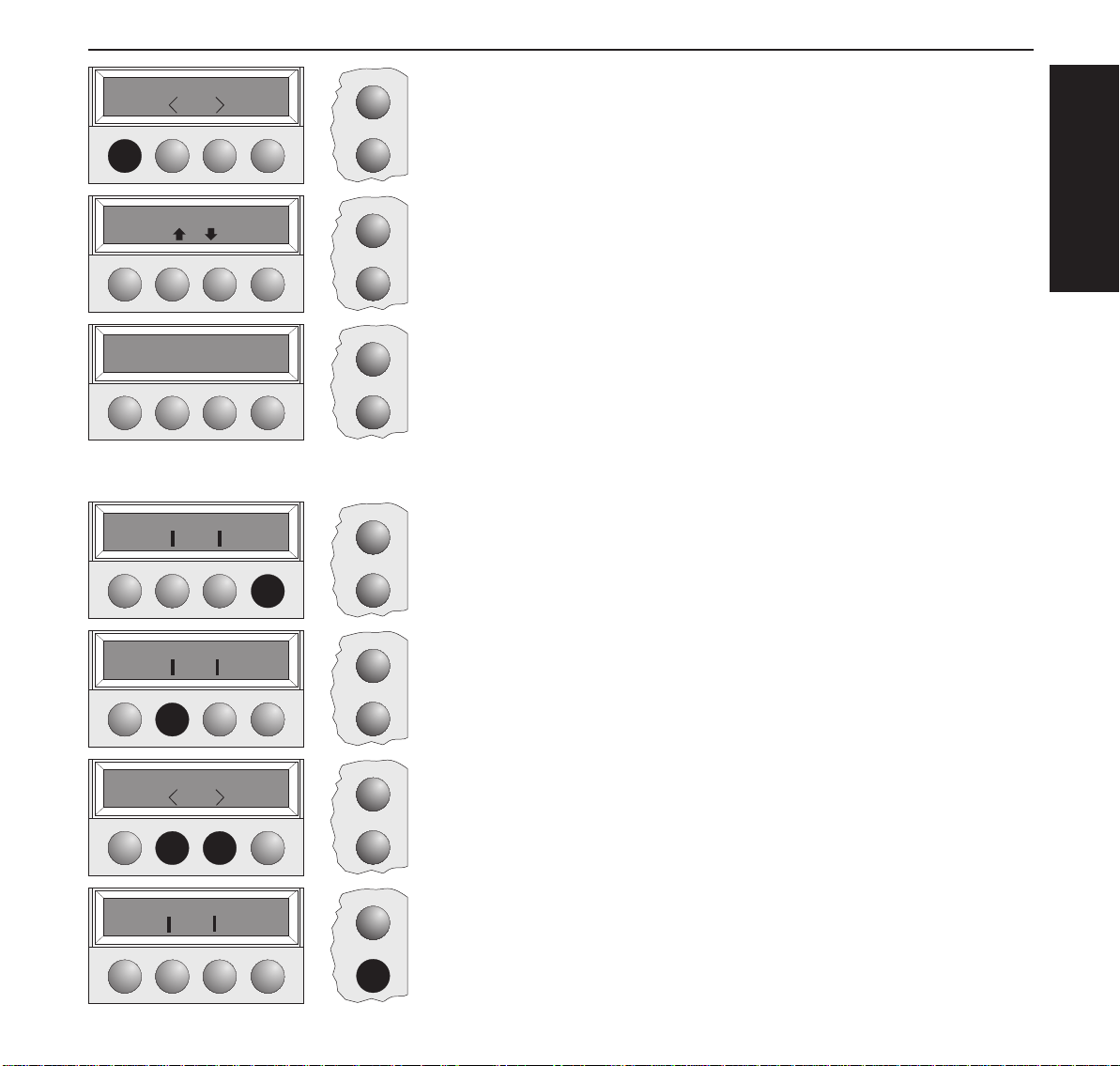
➤Setupmode
Adjust Paperway
Menu Char
➄
➃
➂
➁
Online
Setup
➀
➀SetstheprintertoSetupmode.Inthismode,thefollowingsettingsare
available:
➁Setsthefontandthenumberofcharactersperinch(Charmenu).
➂Paperpath(Paperwaymenu)
➃Tearpositionandfirstprintingline(Adjustmenu)
➄Othermenusettings(Menu)
Accesstotheothermenuoptionsisdisabledbythemanufacturer.Forinformationonhowto
enableaccesstotheseoptionsaswellasabouttheoptionsavailable,refertotheonlinedocumentationontheCD-ROM,chapter1, Operation (Unlock the menu mode).
7
Installing the ribbon cassette Quick start-up
Installing the
ribboncassette
STOP
Latch Lever
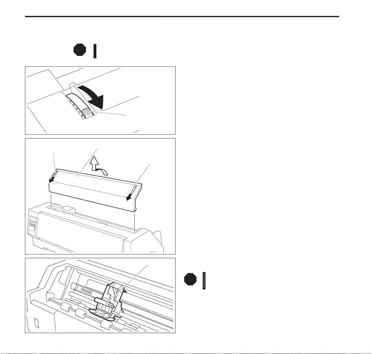
Remove any paper loaded into the printer.
Before opening the cover, make sure that the printer is switched off.
Set the Paper Thickness Adjustment Lever to the “8” position.
Paper Thickness
Adjustment Lever
Access Cover
Latch Lever
Pull the Latch Levers near the right and leftends on the Access
Cover to the front, and detach the entire Access Cover.
Print head
Move the Print head to approximately the center.
STOP
The PrintHead may be hot.So please be carefulnot
to touch the metal part of the Print Head.
8
Quick start-up Installing the ribbon cassette
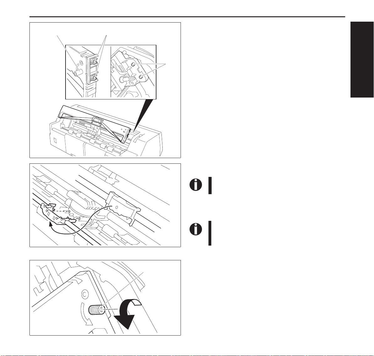
Ribbon Feed Knob
Ink-ribbon
cartridge
Part “A” (left side)
Align the part “A” on the left side of the Ink-ribbon Cartridge
to the two hooks of the printer, push the cartridge all the way
until it clicks. If there is resistance, push it while turning the
Ribbon Feed Knob.
Hooks
ENGLISH
Detach the Ribbon Guide from the Ink-ribbon Cartridge.
Do not detachthe shield that hasbeen attached tothe
Ribbon Guide; it is necessary to protect the ribbon.
Put the Ribbon Guide between the Print Head and the Platen
and push it all the way until it clicks.
Ribbon Feed
Knob
When attaching the RibbonGuide, be careful not to
fold the ribbon. Also, pay attention to the shield so
that it does not become damaged.
Turn the Ribbon Feed Knob in the direction indicated by the
arrow to remove any slack in the ribbon.
9
Loadingpaper Quickstart-up
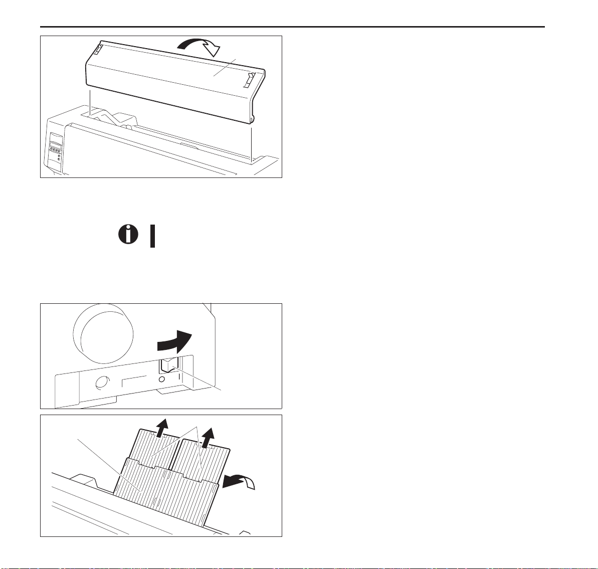
Access
Cover
WhentheInk-ribbonCartridgesettingiscomplete,attachthe
AccessCover.
SetthePaperThicknessAdjustmentLeverinaccordancewith
thethicknessofthepapertobeused.Refertopage18(Setting
theprintheadgap).
Loadingpaper
Onlyusepaperwhichissuitableforthisprinter.Formoreinformation,refertotheonline
documentationontheCD-ROM,AppendixC(Specification).
➤CutSheetpaper CutSheetPaperistobeinsertedfromthefrontoftheprinter.Thepost-printpapercanbefedout
fromtherearorthefront.PleaserefertotheonlinedocumentationontheCD-ROM,Chapter1,
Menu description table.
TurnthePowerSwitchoftheprinterON(“|”).
AdjustthePaperThicknessLeveraccordingtothetypeofpaper
tobeused.Refertopage18(Settingtheprintheadgap).
Paper Tray
10
Power Switch
Paper Extension Trays
StandthePaperTrayupinthedirectionindicatedbythearrow.
WhileholdingthePaperTray,pullupthePaperExtension
Trays.
Quick start-up Loading paper
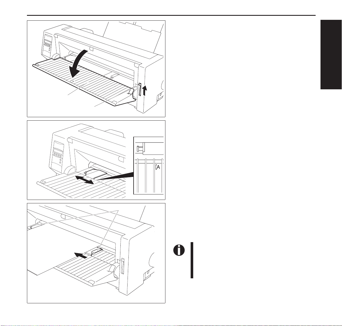
Set the Paper Type Selection Lever to Cut Sheet Paper mode.
Make sure that the printer is in Single Sheet mode. For how to
select Single Sheet mode refer to page 14 (Paper path quick
selection).
Cut Sheet Insert
Guide
Paper Type
Selection Lever
Determine the left margin by moving the Left Paper Guide left
or right. (The “[A” mark indicates the standard print start
position.)
ENGLISH
Cut sheet paper
Paper guides
Placea sheetof paperalignedtotheLeft PaperGuide, andadjust
the Right Paper Guide to the right edge of the paper.
Insert the paper between the Left and Right Paper Guides. The
paper is automatically fed to the print start position and the
printer is ready to print.
The paper feed-out capacity is about 30 sheets in
case 55Kg-paper (ream) is used and the post-print
paper is set to feed out to the rear side. When the
post-print paper is set to feed out to the front, the
paper must be removed sheet by sheet.
11
Loading paper Quick start-up
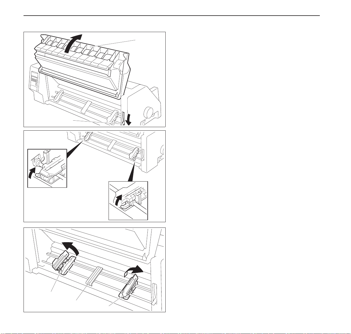
➤ Printer in fanfold paper mode
Paper Type
Selection Lever
Front Cover
Setthe PaperThicknessAdjustment Leveraccording tothe type
of paper to be used. Refer to page 18 (Setting the print head
gap).
Set the Paper Type Selection Lever to Continuous Form Feed
Paper mode.
Open the Front Cover to its upright position until it snaps in.
This prevents unexpected closing of the cover.
Stand the Left and Right Tractor Fixing Levers up (in the
direction indicated by the arrow), and release the locks.
12
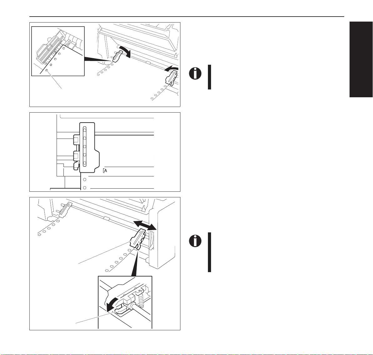
Open the Flaps of the Left and Right Tractors.
Match the Left and Right Tractors to the paper width.
Locate the Paper Plate in the center between the Left and Right
Tractors.
Tractor
Paper Plate
Tractor
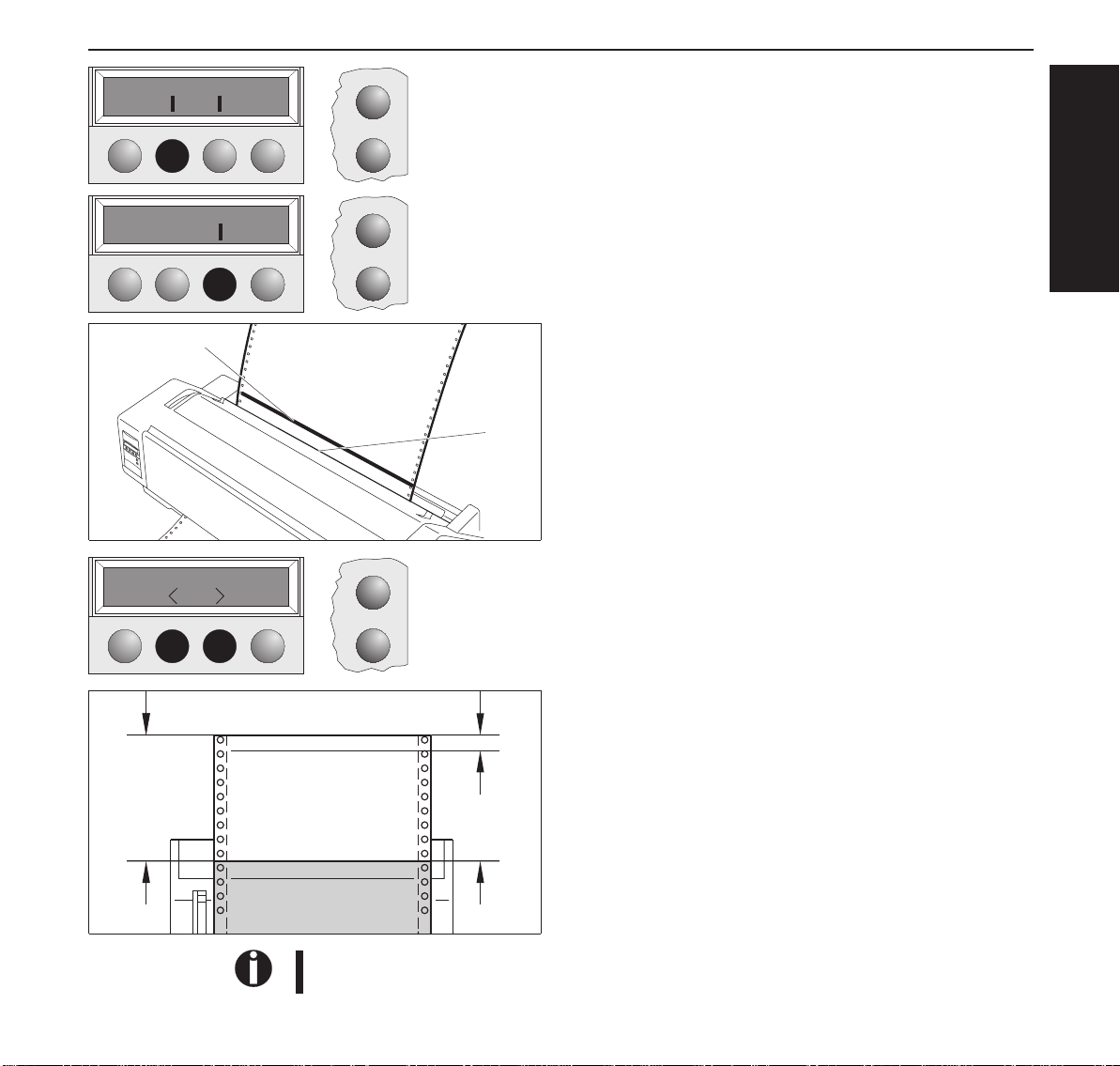
Quick start-up Loading paper
With the printing side of the paper facing up, fit the feeding
holesonthe left edgeofthe paper overthe Left Tractorpins and
close the Paper Flap.
Fitthe feedingholes onthe rightedge ofthepaperovertheRight
Tractor pins, and close the Paper Flap.
To avoid paper jams, ensure that the same left and
right feeding holes are used, and placed over tractor pins of the same level.
Paper Holes over
Tractor Pins
After the paper is set, adjust the left margin by moving the
Tractors left or right. The “[A” mark is the standard print start
position.
ENGLISH
Tractor
Fixing lever
Push down the Left Tractor Fixing Lever to lock the Left
Tractor.
Move the Right Tractor to remove any paper slack, and then
push down the Fixing Lever to lock it in place.
If the paperslackcannot be removed by moving the
Right Tractor alone, adjust the position of the Left
Tractor.
Be careful not to stretch the paper so much that it
tears.
Switch on the printer.
The active feeder (Trac.1) is displayed.
Paper is automatically fed when the printer is in Online status
and receives data from the computer.
Press the Load key to load paper before printing.
13
Changing the paper type Quick start-up
Changing the
papertype
➤ Paper path quick
selection
Offline Trac.1
Park Load
Single Trac.1
Offline Single
Park
Turn paperlever
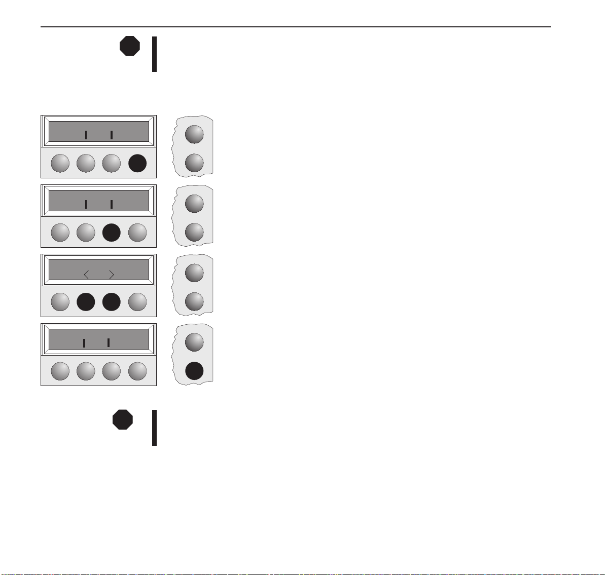
You canchange the paper type(thepaper path) either usingthe paper pathquickselection feature
or via the Setup menu.
First cut the fed-out portion of a Continuous Form Feed Paper at the perforated line. To do this,
proceed as follows.
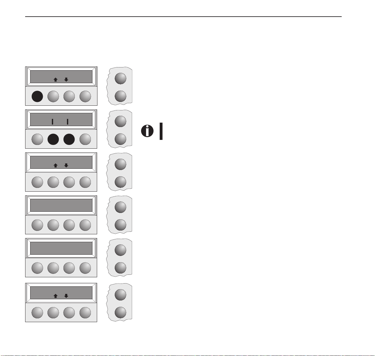
Online
Make sure that the printer is in Offline status; press the Onlinekey, if necessary.
Press the Park key.
Setup
If fanfold paper is in the printer, it is transported to the tear position. “Tear paper
off” appears on the display. Press any key.
If a single sheet is loaded in the printer, it is ejected.
Online
Setup
Online
Select the desired paper path bypressingoneof the Ikeys, inourexample Single.
If you do not make a selection within 5 seconds, the printerexits
the menu.
The printer returns to Offline mode.
The display toggles between…
Setup
and…
Online
SetthePaper TypeSelectionLever toCutSheet Papermode(see page11 Loading
paper).
Setup
Load paper from
Single
Offline Single
Park
14
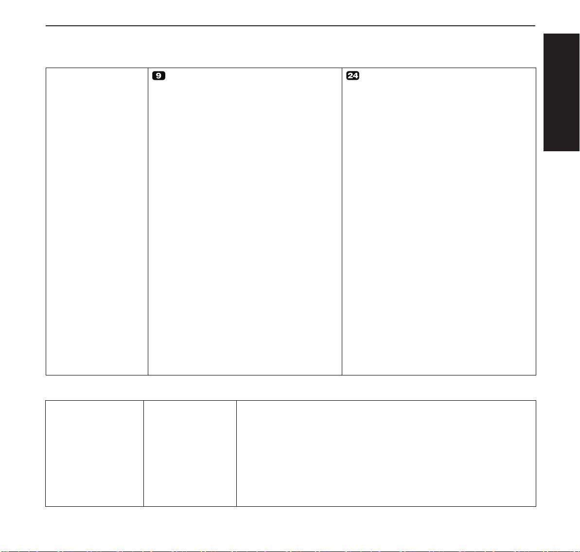
Online
Setup
Online
Setup
The display toggles between…
and…
Stand the Paper Tray up in the direction indicated by the arrow. While holding
the Paper Tray, pull up the Paper Extension Trays.
Determine the left margin by moving the Left Paper Guide left or right.
Place a sheet of paper aligned to the Left Paper Guide, and adjust the Right Paper
Guide to the right edge of the paper. Insert the paper between the Left and Right
PaperGuides. Thepaper isautomatically fedto theprint startposition (seepage11
Loading paper).
Quick start-up Paper transport
Online Single
Online
Setup
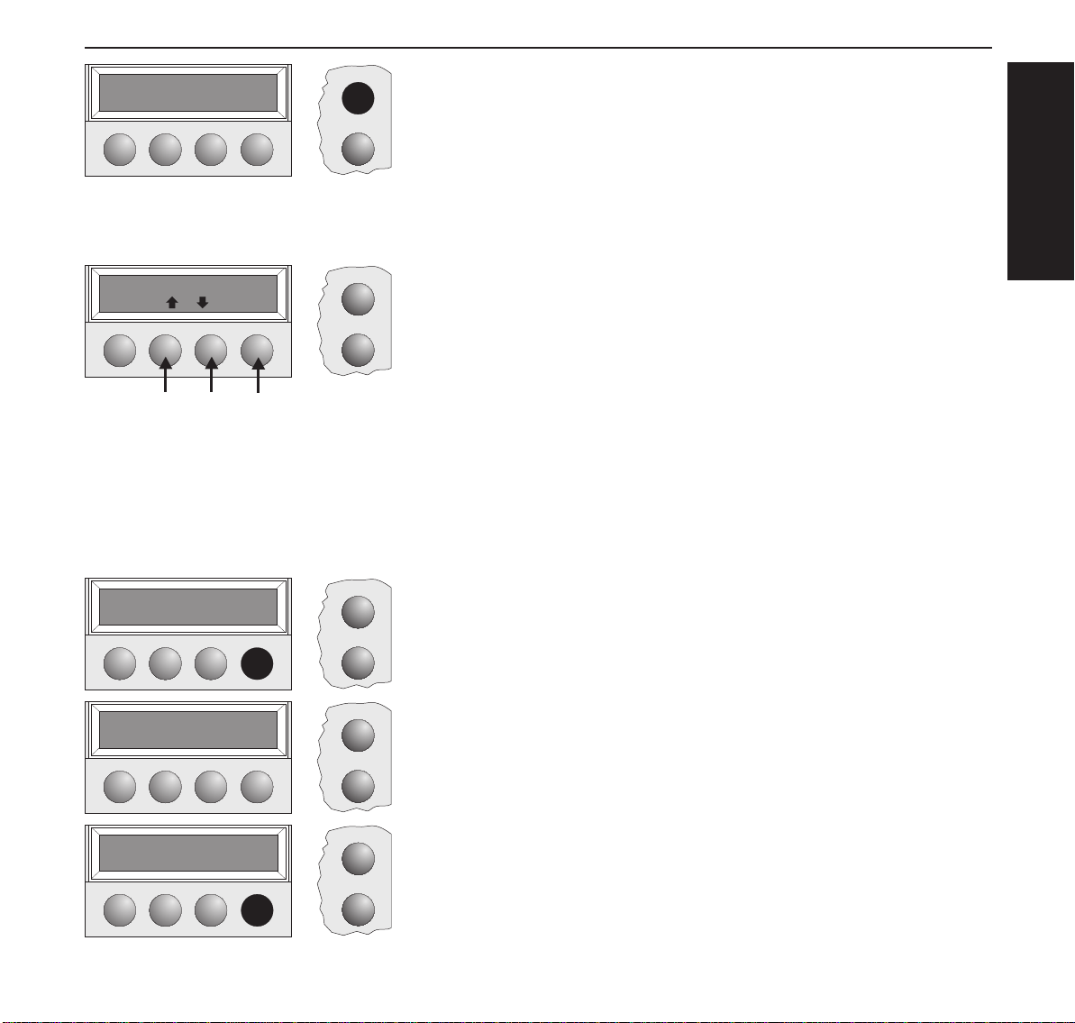
Press the Online key to make the printer ready for operation.
Paper transport Loaded paper (fanfold paper/single sheets) can be transported in the printer in different ways.
Offline Trac.1
Park LF/FF
➂
➁
➀
Online
Setup
Make sure that the printer is in Offline status; press the Online key, if
necessary.
➀ Short keypress: Line feed (LF) is initiated
Long keypress: Form feed (FF) is initiated
➁ Short keypress: Paper is transported downwards step by step
Long keypress: Continuous transport down
➂ Short keypress: Paper is transported upwards step by step
Long keypress: Continuous transport up
Using
➤ Moving paper to the
tear position
Online Trac.1
Tear
Fanfold paper can be transported to the tear position by pressing the Tear key.
Online
Make sure that the printer is in Online status.
Press the Tear key. The printer moves the perforation edge of the fanfold paper
Setup
to the tear edge.
ENGLISH
Tear position
Tractor1
Online Tear
Exit
Online
Setup
Online
Setup
The display toggles between…
and…
Press the Exit key after having torn off the paper. The printer moves the paper
back to the first printing position.
15
Settings (I) Quick start-up
Settings (I)
➤ Setting the tear
position
Offline Trac.1
Park LF/FF
Adjust Paperway
Menu Char
TOF
TearAdj=00/72" *
Set Exit
Tear
If the tear position of the paper is not aligned with the tear edge of the printer, you can adjust it.
Online
Setup
Online
Setup
Online
Setup
Online
Press the Setup key. The printer changes to Setup mode.
Press the Adjust key.
Press the Tear key.
Press the < or > key to move the perforation to the appropriate position.
Confirm thesetting by pressing theSet key. The printer returns toits initial status.
Setup
➤ Setting the first
printing line (TOF)
Adjust Paperway
Menu Char
16
The correction made (a maximum of approx. 2.5 cm [1"] in both directions) will be retained
after printer power-off.
You can use the TOF function to set the position of the topmost printing line individually for
each paper source and each menu.
You should adjust the tear position (see above) before using the TOF function (when using fanfold paper).
Online
Setup
Press the Setup key. The printer changes to Setup mode.
Quick start-up Settings (I)
Adjust Paperway
Menu Char
TOF
Tear
A
FormAdj=12/72" *
Set Exit
Online
Setup
Online
Setup
Online
Setup
Press the Adjust key.
Press the TOF key.
ENGLISH
The bottom edgeof the currently valid firstprintingline A of the
paper is transported to the tear edge B.
The factory setting for the first printing position is 12/72".
B
Press the < or > key to move the first printing line to the appropriate position.
You canset values from0 to 220/72" forfanfold paper,from 0 to72/72" for single
sheets.
Standard 1. print line 12/72"
Newly set 1. print line
The setting made will be retained after printer power-off. For more detailed information, refer to
the online documentation on the CD-ROM, chapter 3 (Mechanical adjustments to the printer).
Confirm the setting by pressing the Set key.
The printer returns to its initial status.
17
Settings (II) Quick start-up
Settings (II)
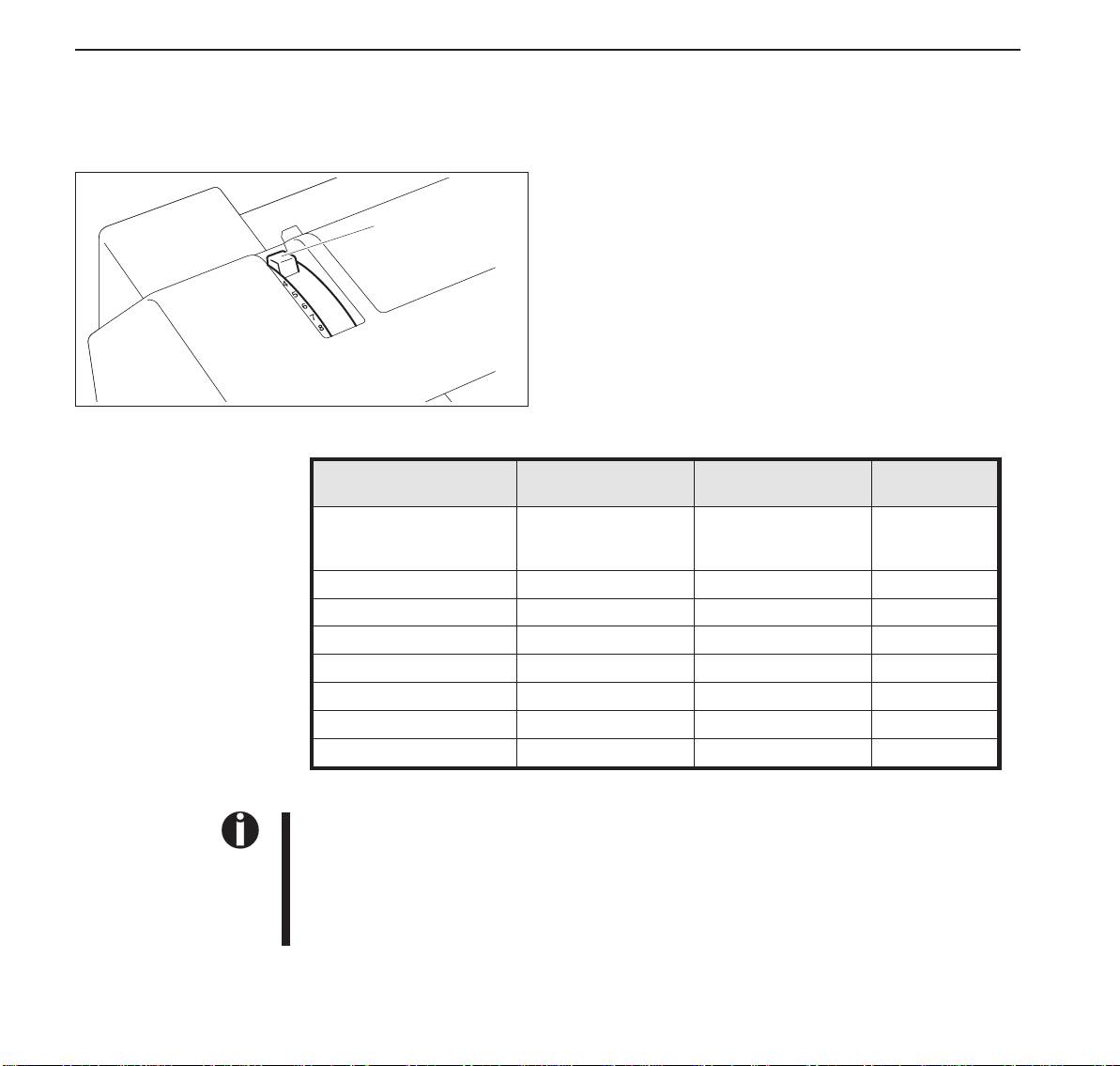
➤ Setting the print
head gap
The printer has been provided with a Paper Thickness Adjustment Lever for adjusting the print
head gap
Toobtain optimumprint quality,the gapbetween thePrintHead
and the Platen needs to be adjusted according to the thickness
Paper Thickness
Adjustment Lever
of the paper to be used.
The following table shows the adjustable range:
Number of Copies/
Thickness of Paper
Original only Thin
Normal
Thick
Original + 1 34/34 40/40
Original + 2 34/34/34 40/40/40
Original + 3 34/34/34/34 40/40/40/40
Original + 4 34/34/34/34/34 40/40/40/40/40
Original + 5 34/34/34/34/34/34 40/40/40/40/40/40
Postal Card 110 130
Reserved — —
Ream (kg) g/m
45–55
55–77
77–110
2
50–65
65–90
90–130
Lever Position
1
1–2
2
2–3
2–4
3–4
4–5
5–6
3
7–8
18
1. “Ream” is a unit of paper thickness, indicating the weight in kg, of 1,000 cut sheets at 788
mm x 1091 mm.
2. When printing the original sheet only, Cut Sheet Paper of 45 kg and thicker or Continuous
Form Feed Paper of 50 kg and thicker can be used.
3. When the Paper Thickness Adjustment Lever is set higher than appropriate, the printout
will appear scratchy and the print head and ribbon lives will be shortened.
Quick start-up Settings (II)
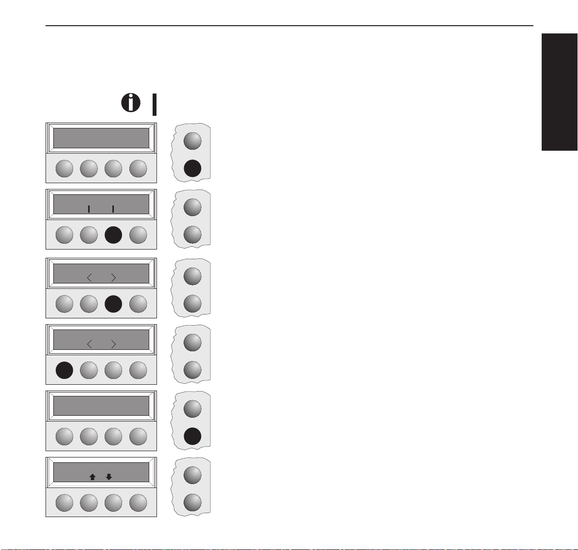
➤Changing paper in
Setup mode
➤From fanfold paper
to single sheet mode
Online Trac.1
Load
Adjust Paperway
Menu Char
Tractor 1 *
Set Exit
Single
Set Exit
When fanfold paper was in use and you want to change over to single sheet mode, proceed as
described below.
You do not need to remove the fanfold paper.
Online
Cut the fed-out portion of the Continuous Form Feed Paper at the perforated line.
To do this, proceed as follows.
Setup
Online
Setup
Online
Setup
Online
Press the Setup key. The printer changes to Setup mode.
Press the Paperway key. The printer changes to the paper path menu.
Press < or > to change to Single (sheet) operating mode.
The currently valid setting (Tractor 1) is marked by a “
*
”.
Confirm the setting by pressing the Set key.
The input is acknowledged by an acoustic signal and the fanfold paper is trans-
Setup
ported to the tear position. Cut the fed-out portion of the Continuous Form Feed
Paper at the perforated line.
In the display appears…
ENGLISH
Tear paper off
Press any key
Offline Single
Park Load
Online
Setup
Online
Setup
Press any key.
The printer returns to its initial status and the fanfold paper is transported to the
park position.
The display toggles between…
and…
19
Settings (II) Quick start-up
Turn paperlever
Load paper from
Single
Online Single
➤ From single sheet to
fanfold paper mode
Online Single
Online
Setup
Set the Paper Type Selection Lever to Cut Sheet Paper mode.
In the display appears…
Online
Stand the Paper Tray up and pull up the Paper Extension Trays (see page 10).
Place a sheet of paper aligned to the Left Paper Guide, and adjust the Right Paper
Setup
Guide to the right edge of the paper.
Insert the paper between the Left and Right Paper Guides. The paper is automatically fed to the print start position (see page 11).
Online
Setup
Press the Online key to make the printer ready for operation.
When single sheets were in use and you want to change over to fanfold paper mode, proceed as
described below.
Make sure that fanfold paper is loaded. Refer to page 12 (Loading Fanfold Paper) for details.
Online
Pull down the Paper Extension Trays and fold the Paper tray down.
Press the Setup key. The printer changes to Setup mode.
Setup
Adjust Paperway
Menu Char
Single
Set Exit
20
Online
Setup
Online
*
Setup
Press the Paperway key. The printer changes to the paper path menu.
Press < or > to change to Trac.1 (fanfold paper) mode.
The currently valid setting (Single) is marked by a “
*
”.
Quick start-up Settings (II)
Tractor1
Set Exit
Offline Trac.1
Online
Setup
Online
Confirm the settingbypressing the Set key. An acoustic signal acknowledges the
input.
The display toggles between…
Park LF/FF
Setup
and…
Turn paperlever
Online
Setup
Shift the Paper Type Selection Lever to the position needed.
The printer is now ready for printing fanfold paper.
Press the Online key to make the printer ready for operation.
➤ Selecting a font You can use the Font key to select fonts in Setup mode.
Adjust Paperway
Menu Char
Online
Setup
Press the Setup key.
Press the Char key.
ENGLISH
Font CPI
DRAFT COPY *
Set Exit
Font CPI
Online
Setup
Online
Setup
Online
Setup
Press the Font key.
Press the < or > key to select the desired font.
Confirm your selection by pressing the Set key.
Press the Setup key. The printer returns to its initial status.
You can also press the Online key. The printer changes directly in Online mode.
21
Settings(II) Quickstart-up
STOP
➤Settingthe
characterpitch
Adjust Paperway
Menu Char
Font CPI
10CPI *
Set Exit
Font CPI
Theselectionmadewillnotberetainedafterprinterpower-off.Forinformationonhowtoselectafontpermanently,refertoonlinedocumentationontheCD-ROM,chapter1(Menu
description table).
YoucanusetheCPIkeytosetthecharacterpitchinSetupmode.
Online
PresstheSetupkey.
PresstheCharkey.
Setup
Online
Setup
Online
PresstheCPIkey.
Pressthe<or>keytoselectthedesiredpitch.
ConfirmyourselectionbypressingtheSetkey.
Setup
Online
PresstheSetupkey.Theprinterreturnstoitsinitialstatus.
YoucanalsopresstheOnlinekey.TheprinterchangesdirectlyinOnlinemode.
Setup
22
STOP
Theselectionmadewillnotberetainedafterprin terpower-of f.Forinfo rmationonhowtose lecta
fontpermanently,refertoonlinedocumentationontheCD-ROM,chapter1(Menu description
table).
Quick start-up Specifications
Specifications
➤Printer specifications
Printing method serial printing with 9-pin matrix print head serial printing with 24-pin matrix print head
Print width narrow printer 80 characters at 10 cpi
wide printer 136 characters at 10 cpi
Print speed (bidirectional) LN-Draft 413 cps at 10 cpi
Draft 310 cps at 10 cpi
NLQ 77 cps at 10 cpi
Character densities 5, 6, 7.5, 8.6, 10, 12, 15, 17.1, 20 cpi
(HS-Draft: 10, 12 cpi only)
Graphics print density horizontal 240 dpi / vertical 144 dpi horizontal 360 dpi / vertical 180 dpi
Ribbon life 4 million char. 4 million char.
Acoustic noise levell ca. 55 dB (A) ca. 55 dB (A)
Dimensions narrow printer 485 x 206 x 272 mm (W x H x D)
wide printer 625 x 206 x 272 mm (W x H x D)
Weight narrow printer 9 kg / wide printer 11 kg narrow printer 9 kg / wide printer 11 kg
Power supply USA/Canada AC 120 V 10% / 60 Hz 3%
Europe AC 230 V 10%/ 5 0Hz 3%
Power consumption at 100% throughput < 60 VA
in the Ready state < 10 VA
Operating environment Temperature 10ºC to 40ºC
Humidity 20% to 80%
Print head specifications Number of pins 9
Pin diameters 0,3 mm
Number of copies 1 original + 5 copies
Interface buffer max. 64 kB max. 64 kB
Regulations UL 1950, VDE-GS, CE, FCC Class B, UL/Ulc UL 1950, VDE-GS, CE, FCC Class B, UL/ULc
narrow printer 80 characters at 10 cpi
wide printer 136 characters at 10 cpi
Draft 409 cps at 10 cpi
Draft Copy 275 cps at 10 cpi
NLQ/LQ 92 cps at 10 cpi
5, 6, 7.5, 8.6, 10, 12, 15, 17.1, 20 cpi
narrow printer 485 x 206 x 272 mm (W x H x D)
wide printer 625 x 206 x 272 mm (W x H x D)
USA/Canada AC 120 V 10% / 60 Hz 3%
Europe AC 230 V 10% / 5 0 Hz 3%
at 100% throughput < 60 VA
in the Ready state < 10 VA
Temperature 10ºC to 40ºC
Humidity 20% to 80%
Number of pins 24
Pin diameters 0,22 mm
Number of copies 1 original + 3 copies
ENGLISH
➤ Paper specifications
Cut sheets Paper weight
Fanfold paper
Simple forms
Sets of forms
Width
Length
Paper weight
Width
Length
Paper weight
Width/Length
Form thickness
Number of copies
60 – 120 g/m
narrow printer: 76 – 220 mm / wide printer: 76 – 420 mm
76 – 559 mm
60 – 120 g/m
narrow printer: 76 – 254 mm / wide printer: 76 – 420 mm
76 – 559 mm
original: 45 – 65 g/m
see simple forms
max. 0,5 mm
1+5 (9 wire) / 1+3 (24 wire)
2
2
2
/ copy: 45 – 56 g/m
2
/ last page: 45 – 65 g/m
2
23
Accessories Quick start-up
For more information on printer specifications and paper specifications, refer to the online
documentation on the CD-ROM.
Accessories Ribbon cassettes
Narrow printer: Part No. 044 829
Wide printer: Part No. 044 830
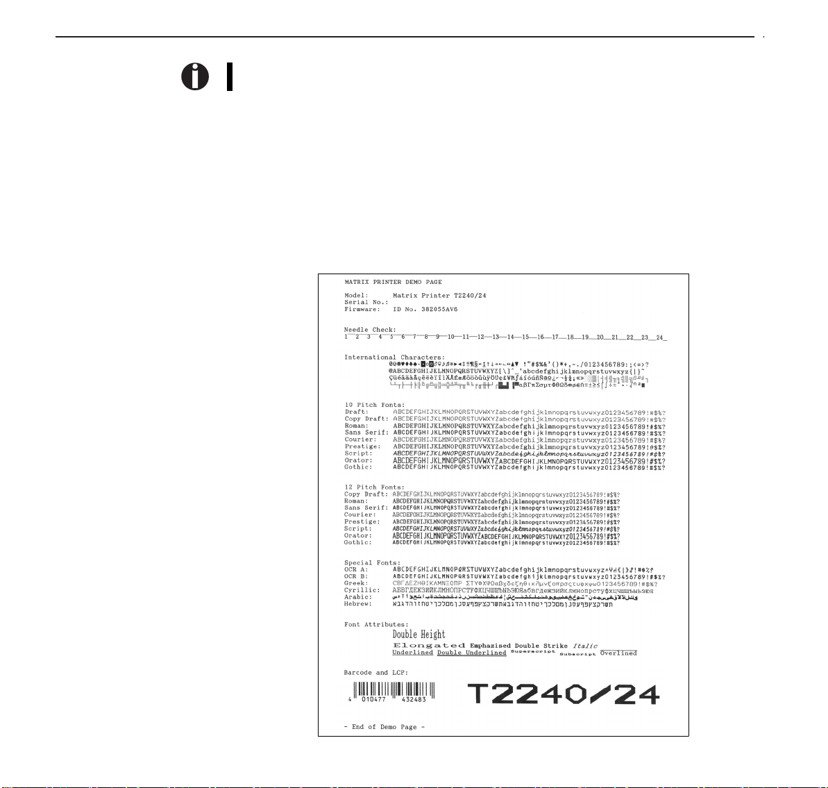
Demo page The demo page contains information on the firmware version, serial number, needle check,
fonts, font attributes and bar codes/LCP.
Hold down button 4 while switching on the printer to print the demo page.
To terminate printing, switch off the printer.
24

Der schnelle Einstieg
Bedienungsanleitung
Inhaltsverzeichnis
DER SCHNELLE
EINSTIEG
Einführung 2
Zu den verwendeten Symbolen 2
Wichtige Sicherheitshinweise 2
Arbeiten mit der Online-Dokumentation 2
Auf einen Blick 3
Installation 5
Drucker auspacken 5
Drucker aufstellen 5
Drucker anschließen 6
Drucker ein- und ausschalten 6
Bedienfeld 7
Online-Modus 7
Offline-Modus 7
Setup-Modus 7
Farbbandkassette auswechseln 8
Papier einlegen 10
Einzelblattpapier 10
Drucker im Endlospapierbetrieb 12
Papierart wechseln 14
Schnellumschaltung Papierweg 14
Papiertransport 15
Handhabung 15
Papier in Abreißposition fahren 15
Einstellungen (I) 16
Abreißpositioneinstellen 16
Erste Druckzeile einstellen (TOF) 16
Einstellungen (II) 18
Druckkopfabstand einstellen 18
Papierwechsel im Setup-Modus 19
Von Endlospapier- in Einzelblattbetrieb 19
Von Einzelblatt- in Endlospapierbetrieb 20
Schriftart wählen 21
Zeichendichte einstellen 22
Technische Daten 23
Druckerspezifikationen 23
Papierspezifikationen 23
Zubehör 24
DEUTSCH
1

Einführung Der schnelle Einstieg
Einführung Diese Bedienungsanleitung dient dem schnellen Einstieg in das Arbeiten mit dem Drucker und
Ah ha!
➤Zu den verwendeten
Symbolen
STOP
➤Wichtige
Sicherheitshinweise
STOP
soll auch dem ungeübten Benutzer den Umgang mit dem Gerät ermöglichen. Sie beschreibt die
wichtigsten Funktionen des Druckers und enthält unerläßliche Informationen für die alltägliche
Arbeit mit dem Gerät. Eine ausführliche Beschreibung des Druckers, seiner Leistungsmerkmale
und weiterführende Informationen enthält das Referenzhandbuch auf der Online-CD-ROM, die
Sie auf der vorletzten Seite dieser Bedienungsanleitung finden.
In der Bedienungsanleitung werden zwei Arten besonderer Hinweise verwendet, um wichtige
Informationen hervorzuheben.
VORSICHT enthält Informationen, die beachtet werden müssen, um den Benutzer vor Schaden
zu bewahren und Schäden am Drucker zu verhindern.
HINWEIS enthält allgemeine oder zusätzliche Informationen zu einem bestimmten Thema.
Lesen Sie die folgenden Hinweise genau durch, bevor Sie den Drucker in Betrieb nehmen.
Dadurch schützen Sie sich und vermeiden Schäden an dem Gerät.
Bewahren Sie diese Bedienungsanleitung an einem jederzeit zugänglichen Ort auf.
Den Drucker auf stabilem Untergrund so aufstellen, daß er nicht zu Boden fallen kann.
Den Drucker weder hohen Temperaturen noch direktem Sonnenlicht aussetzen.
Keine Flüssigkeiten mit dem Drucker in Berührung bringen.
Den Drucker keinen Erschütterungen, Stößen oder Vibrationen aussetzen.
Den Drucker nur an eine Steckdose mit der richtigen Wechselspannung anschließen.
Führen Sie Wartungsarbeiten und Reparaturen keinesfalls selbst aus, sondern verständigen
Sie immer einen qualifizierten Servicetechniker.
STOP
➤Arbeiten mit der On-
line-Dokumentation
Wenn Sie den Drucker vom Netz trennen wollen, immer den Netzstecker an der Steckdose
ziehen.
Weitere Sicherheitshinweise finden Sie an entsprechender Stelle im Text.
Installieren Sie zuerst den Adobe Acrobat Reader auf Festplatte, falls dieses Programm nicht
schon vorhanden ist. Befolgen Sie zur Installation die in der Readme-Datei im Verzeichnis
READER aufgeführten Schritte. Doppelklicken Sie zum Starten der Online-Dokumentation im
Datei-Manager (Windows 3.1) oder Explorer (Windows 95/Windows 98/Windows NT) auf die
Datei START.PDF. Folgen Sie dann der Bedienerführung.
Für den Fall, daß die CD-ROM fehlerhaft ist oder fehlt, wenden Sie sich bitte an -Ihren Händler.
Die Online-Dokumentation ist auch in gedruckter Form (gegen -Gebühr) oder im Internet
erhältlich.
Hardwarevoraussetzungen mindestens: PC AT 486, 4-fach CD-ROM, 15"-Bildschirm, Maus.
➤ Fehlersuche Die Online-Dokumentation auf CD-ROM enthält ausführliche Informationen zur Fehlersuche.
2
Der schnelle Einstieg Auf einen Blick
Auf einenBlick In den folgenden Abbildungen sind alle Druckerteile aufgeführt, die sich daran anschließende
Tabelle listet die Funktionen dieser Teile auf.
Papierablage
Papierstützen
Bedienfeld
Linker Randsteller
Rasthebel
Hintere
Abdeckleiste
Netzanschluß
Einzelblatteinzug
Rechter Randsteller
Papierabreißkante
Frontklappe
Papierdickenhebel
Obere Abdeckung
Handrad
Netzschalter
Optionenbuchse
Papierwahlhebel
DEUTSCH
Schnittstellenbuchse
Rasthebel
3

Auf einen Blick Der schnelle Einstieg
Bezeichnung Funktion
Bedienfeld Zeigt den Druckerstatusan; wird verwendet, um zahlreiche Einstellungen
Papierablage Wird als Papierablagefür schon bedruckte Einzelblätter verwendet, wenn
Papierstützen Dienen zur Verlängerung der Papierablage.
Obere Abdeckung Soll eine Farbbandkassette ersetzt, oder muß ein Papierstau beseitig
Handrad Wird verwendet, um Papier manuell vor oder zurückzubewegen.
Netzschalter Schaltet den Drucker EIN oder AUS.
Optionenbuchse Wird verwendet, um die automatischeEinzelblattzuführung (ASF) oder
Papierwahlhebel Wird verwendet, um die vom Druckerzu verarbeitende Papierart zu
Frontklappe Wird geöffnet, wenn Endlospapier eingelegt werden soll. Diese Klappe ist
Rechter Randsteller Durch Ausrichten des rechten Rands eines Einzelblatts an dieser Führung
Einzelblatteinzug Wird geöffnet, um Einzelblätter einzuführen und dient als Papierstütze.
Linker Randsteller Dient der Ausrichtung des linken Rands von Einzelblättern.
Rasthebel Ziehen der Hebel in Richtung Druckervorderseite öffnet die Verriegelung
Papierabreißkante An dieser Stelle wird Endlospapier abgerissen. Drücken der Taste Tear
Papierdickenhebel Wird verwendet, um den Druckkopfabstand in Überein-
Schnittstellenbuchse Hier wird das Kabel für den Anschluß an den Computer eingesteckt.
Netzanschlußbuchse Hier wird das Netzkabel angeschlossen.
Hintere Abdeckleiste Dientzur Geräuschdämmung am Drucker. Muß abgenommen werden,
vorzunehmen.
der Parameter „F-Eject“in den Menüeinstellungen auf AUS gesetzt ist.
werden, kann diese Abdeckung entfernt werden, um Zugang zu den
betroffenen Teilen zu erhalten.Dient außerdem dem Schutz des
Bedieners vor den mechanischen Bewegungen im Drucker.
den optionalen zweiten Traktor anzuschließen.
wählen:
Einzelblattpapier (Hebel in oberer Position)
Endlospapier (Hebel in unterer Position)
abgenommen, wenn die automatischeEinzelblattzuführung (ASF) oder
der optionale zweite Traktor angebracht ist.
kann ein ungleichmäßigerPapiereinzug verhindert werden.
Wird außerdem als Ablagefür bedrucktes Papier verwendet, wenn der
Parameter „F-Eject“in den Menüeinstellungen auf ASF, Singleoder ALL
gesetzt ist.
und die obere Abdeckung kann geöffnet werden.
transportiert das Papierbis zu dieser Position.
stimmung mit der verwendetenPapierdicke einzustellen. Einzelheiten
siehe Seite 18,
wenn die Papierablagehochgeklappt wird.
Druckkopfabstand einstellen.
4
 Loading...