

Page 1

7265
Programmer's Manual
Matrix printer
Page 2

Table of Contents
Chapter 1. Introduction............................................................................................................1
Chapter 2. ANSI......................................................................................................................2
Control Code Summary .......................................................................................................3
Control Code Comparison, 7 Bit/8 Bit..................................................................................4
8-bit Control Codes..............................................................................................................4
Escape Sequence Summary ...............................................................................................6
Printer Handshaking............................................................................................................8
Printer Control .....................................................................................................................9
Graphics Rendition (Fonts and Modes) .............................................................................15
NATIONAL CHARACTER SET......................................................................................16
Forms Setup......................................................................................................................20
Superscript/Subscript.........................................................................................................21
Vertical Movement.............................................................................................................22
Margins..............................................................................................................................25
Horizontal Movement.........................................................................................................26
Tabs...................................................................................................................................28
Dot Graphics......................................................................................................................29
Sample Basic Program for Dot Coding ..........................................................................30
Graphics Control Functions............................................................................................31
7265 Programmer’s Manual
Copyright © 2004 TallyGenicom
i
Page 3

Table of Contents
Chapter 3. ANSI Bar Codes....................................................................................................33
Before You Begin - Set the Form Length.............................................................................34
Setting Bar Code Parameters..............................................................................................35
General Rules for Assigning Parameters.........................................................................36
Bar Code Command Sequences .....................................................................................37
Element Widths................................................................................................................39
Other Parameters.............................................................................................................40
Delimiters.............................................................................................................................42
Horizontal Tab Delimiter...................................................................................................44
Horizontal Position - Relative Delimiter............................................................................45
Calculating Characters per Inch ..........................................................................................47
Bar Code Style Characteristics............................................................................................48
Interleaved 2 of 5 (Style 0)...............................................................................................48
Bidirectional/Industrial 2 of 5 (Styles 1 and 3)..................................................................48
Matrix 2 of 5 (Style 2).......................................................................................................49
Code 3 of 9 (Style 4) ........................................................................................................49
EAN-8 (Style 5)................................................................................................................50
EAN-13 (Style 6)..............................................................................................................50
Code 11 (Style 7).............................................................................................................51
Codabar A/t, B/n, C/*, D/e (9, 10, 11, 12).........................................................................52
UPC-A (Style 13)..............................................................................................................52
UPC-E (Style 14)..............................................................................................................53
Code 93 (Style 15)...........................................................................................................54
Code 128 (Style 16) .........................................................................................................54
MSI (Style 19) ..................................................................................................................55
POSTNET (Style 50)........................................................................................................56
Calculating the Checksum for Code 3 of 9 ..........................................................................58
Calculating the Checksum for CODE 93..............................................................................58
Code 93 Checksums for Full ASCII..................................................................................60
Chapter 4. ANSI Oversized Font.............................................................................................63
Control Function Summary..................................................................................................64
Oversized Control Functions ...............................................................................................64
Oversized Versus Expanded ...............................................................................................66
Setting the Expansion..........................................................................................................66
Device Timeout with Very Large Characters .......................................................................67
What is a Character Cell ?...................................................................................................68
Oversized Character Dimensions – 0
Oversized Character Dimensions - 270
o
...............................................................................69
o
...................................................................................70
Vertical Position-Relative in Oversized................................................................................70
Implementing the Line Feed Function - 0
Line Spacing and Intercharacter Spacing – 270
7265 Programmer’s Manual
Copyright © 2004 TallyGenicom
o
..........................................................................71
o
................................................................72
ii
Page 4

Table of Figures
Figure 2-1 Default Character Set for ANSI Emulation, 00 to 7F
........................................5
Figure 2-2 Default Character Set for ANSI Emulation, 80 to FF..............................................6
Figure 2-3 National Character Substitutions 0 - 18 ...............................................................17
Figure 2-4 Effects of Character Spacing Parameters............................................................22
Figure 2-5 Dot Column Coding..............................................................................................29
Figure 2-6 Dot Graphics Example ........................................................................................30
Figure 3-1 Parts of a Bar Code ............................................................................................35
Figure 3-2 Effects of Rotation Parameters ............................................................................40
Figure 3-3 Comma, Space, and Asterisk Delimiters..............................................................43
Figure 3-4 Horizontal Tab Delimiter.......................................................................................44
Figure 3-5 Horizontal Position-Relative Delimiter..................................................................45
Figure 3-6 Vertical Bar Code Sumbols.................................................................................46
Figure 4-1 Expanded and Oversized.....................................................................................66
Figure 4-2 Character Cells ....................................................................................................68
Figure 4-3 Vertical Character Dimensions.............................................................................69
Figure 4-4 Sideways Character Dimensions .........................................................................70
7265 Programmer’s Manual
Copyright © 2004 TallyGenicom
iii
Page 5

Chapter 1.
Introduction
The TallyGenicom 7265 provides rugged, versatile impact printers useful in a variety of
applications. Flexibility of use is guaranteed by the wide range of software emulations and
programming options. The current printer characteristics are the result of years of application
experience. It is a hallmark of TallyGenicom products that they may be used with a broad
range of systems, hardware, emulations, and protocols.
All trademarks and registered trademarks are property of their respective holders.
CENTRONICS of GENICOM LLC Epson of Epson America, Incorporated
DEC of COMPAQ Corporation GENICOM of TallyGenicom LP
IBM and Proprinter of International Business Machines Corporation
The information in this manual is believed to be accurate and correct. However, TallyGenicom
makes no claim as to its absolute accuracy and reserves the right to make improvements to this
document from time to time.
7265 Programmer’s Manual
Copyright © 2004 TallyGenicom Chapter 1 Introduction
1
Page 6

ANSI
The TallyGenicom im ple m entation of ANSI X3.64 is the native control protocol for the 7265
printer, as it is for a variety of other TallyGenicom impact matrix printer families. The control
functions presented here are a superset of ANSI control sets familiar to our customers. For the
most part, ANSI drivers written for other TallyGenicom printers should only need to be modified as
features introduced on the 7265 Series printers are exercised. Examples of such new features
include user-defined formats, alternate paper paths, user-defined character substitutions, and
remote selection of emulations.
Enabling the application to select among emulations provides access to some of the 7265
features not supported in emulated products. Toward this end, the printer can be commanded to
maintain the current status of fonts, pitches, tabs, margins and so forth across emulation
changes. Although some minute differences due to translations from, say, columns to decipoints
may be discernible when switching from one emulation to another, the printer is quite predictable
when switching from another emulation to ANSI and then back again.
The 7265 is a decipoint machine. Locations and dimensions such as tabs, margins, absolute and
relative positions, and form lengths are described in ANSI control sequences in units of 1/720
inch. If you have the choice of describing your page in one or another of the supported
emulations, consider that ANSI gives you more flexible control of locations of objects on the page.
In this chapter we include spaces between characters in escape sequences for clarity. ESC H,
for instance, is easier to read than is ESCH. Where the space character forms a component of a
control sequence, then it is designated by <SP> .
Listed below are the control codes interpreted by this printer, along with page numbers where you
can find detailed descriptions.
7265 Programmer’s Manual
Copyright © 2004 TallyGenicom
2
Page 7
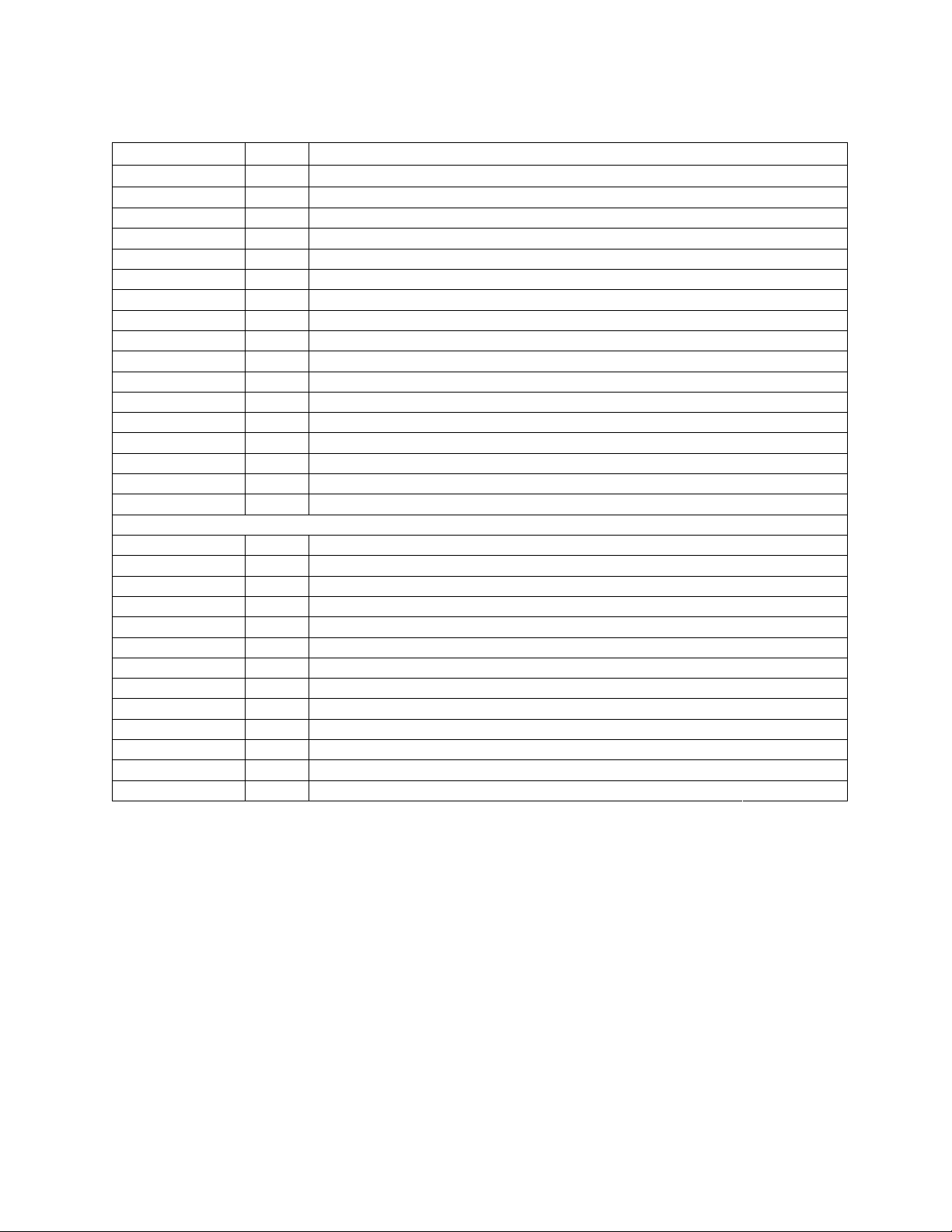
Control Code Summary
Code Hex Description
ETX 03 ETX/ACK Communication Protocol
ACK 06 ETX/ACK Communication Protocol
BEL 07 Sound Beeper
BS 08 Backspace
HT 09 Horizontal Tab
LF 0A Line Feed
VT 0B Vertical Tab
FF 0C Form Feed
CR 0D Carriage Return
SO 0E Barcode / Oversized On
SI 0F Barcode / Oversized Off
DC1(XON) 11 Printer Ready
DC3(XOFF) 13 Printer Busy
ESC 1B Escape
DEL 7F Delete
If 8-bit control code interpretation is enabled ...
IND 84 Index
NEL 85 Next Line
HTS 88 Set Horizontal Tab
VTS 8A Set Vertical Tab
PLD 8B Partial Line Down
PLU 8C Partial Line Up
RI 8D Reverse Index
DCS 90 Device Control String
PU1 91 Private Use 1
CSI 9B Control String Introducer
ST 9C String Terminator
OSC 9D Straps and Options Introducer
Some of the control codes are interpreted when encountered within a graphics data sequence.
Interpretations relative to graphics are shown on page 31.
7265 Programmer’s Manual
Copyright © 2004 TallyGenicom Chapter 2 ANSI
3
Page 8
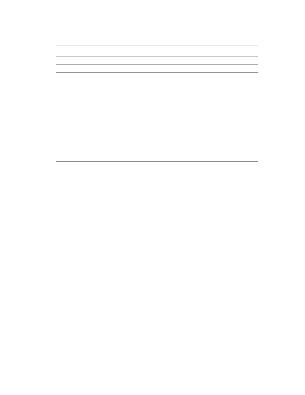
ompar ison, 7 Bi t/ 8 Bi t
8 B i t Hex Description 7 Bit Hex
IND 84 Index ESC D 1B 44
NEL 85 Next Line ESC E 1B 45
HTS 88 Set Horizontal Tab ESC H 1B 48
VTS 8A Set Vertical Tab ESC J 1 B 4A
PLD 8B Partial Line Down ESC K 1B 4B
PLU 8C Partial Line Up ESC L 1B 4C
RI 8D Reverse Index ESC M 1B 4D
DCS 90 Device Control String ESC P 1B 50
PU1 91 Private Use 1 ESC Q 1B 51
CSI 9B Control String Introducer ESC [ 1B 5B
ST 9C String Terminat or ESC \ 1B 5C
OSC 9D Straps and Options Introducer ESC ] 1B 5D
8-bit Control Codes
ANSI assigns control functions to characters 80 hex through 9F hex and calls these characters
C1 codes. You can set the printer to either interpret 80 hex - 9F hex as control codes or not. The
ISU default status of this option is disabled.
You can toggle the status of the 8-bit control code enable from the Emulations Options Menu or
with escape sequences. The pertinent escape sequences are the ANSI private use sequences
described on page 12. In 8-bit mode, all of the lower contro l codes and ESC sequences remain
active. For example, you can use either PLD or ESC K for subscript printing. In 7-bit mode, only
ESC K is available.
If 8-bit control code interpretation is disabled, then the printer processes characters 80 hex
through 9F hex according to IBM PC character sets 1 or 2, depending on which is currently
selected. The default is character set 1. You can toggle the character set selection from the
Emulation Options Menu.
If 8-bit control code interpretation is disabled and character set 1 is active, then the printer strips
the most significant bit of characters 80 hex through 9F hex. For example, if you send 8A hex
when 8-bit control code interpretation is disabled and character set 1 is active, then the printer
treats 8A hex as 0A hex and performs a line feed.
7265 Programmer’s Manual
Copyright © 2004 TallyGenicom
4
Page 9
0 123 456 7
00 NUL@P`p
1 DC1 !1AQaq
2“2BRbr
3 ETX DC3 #3CScs
4$4DTdt
5 ENQ %5EUeu
6 ACK &6FVfv
7 BEL ‘7GWgw
8 BS (8HXhx
9 HT )9IYIy
A LF *:JZjz
B VT ESC +;K[k{
C FF ,<L\ l|
D CR -=M]m}
E SO .>N^n~
F SI /?O_oDEL
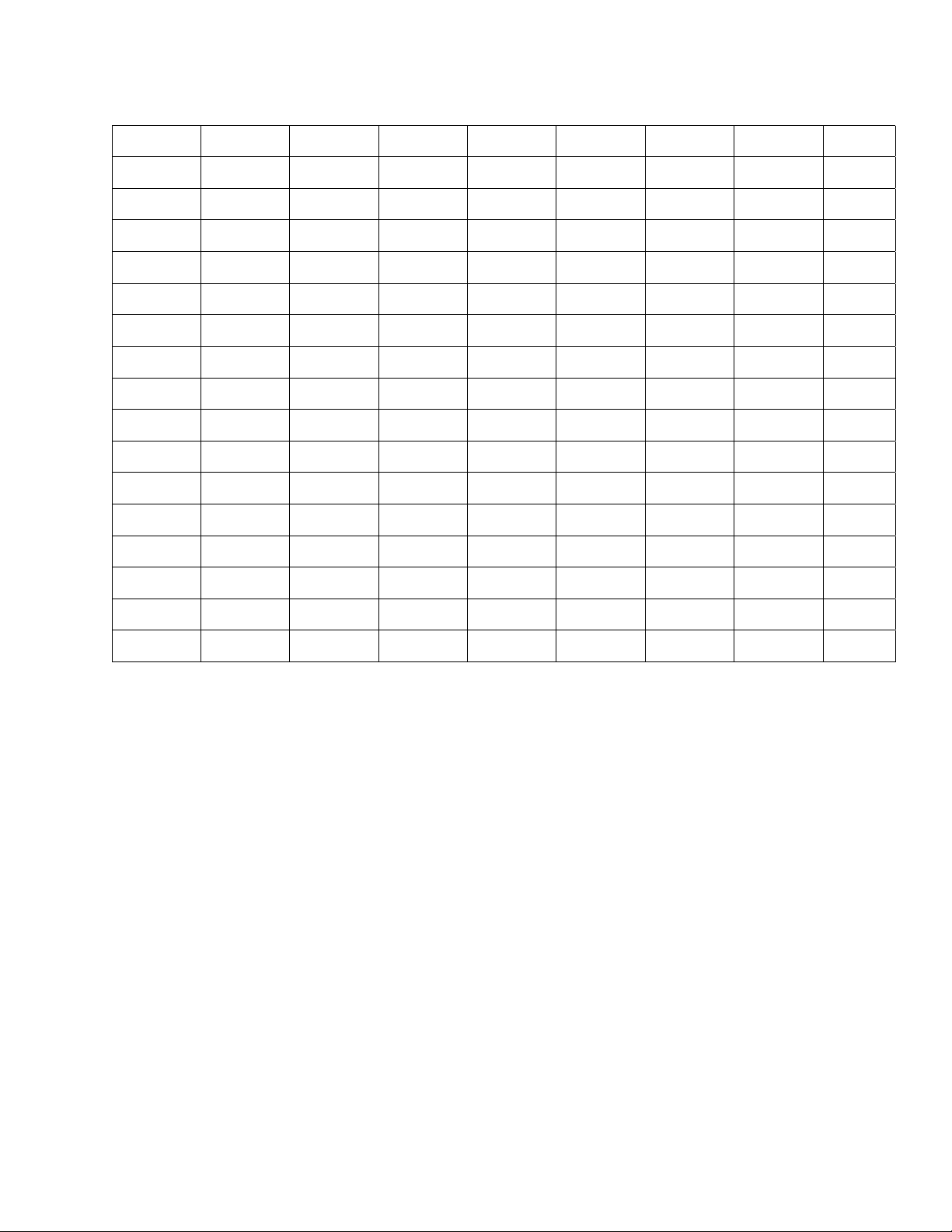
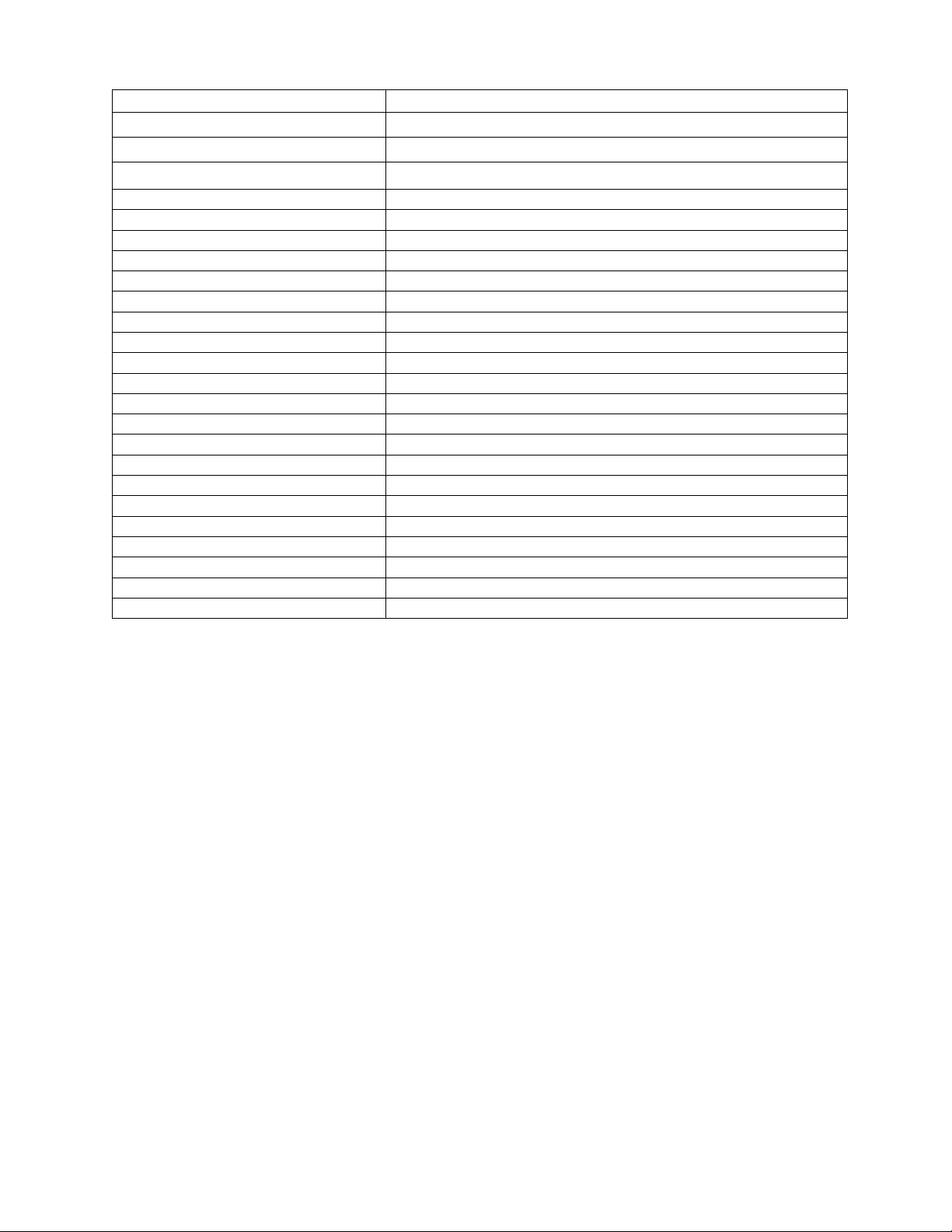
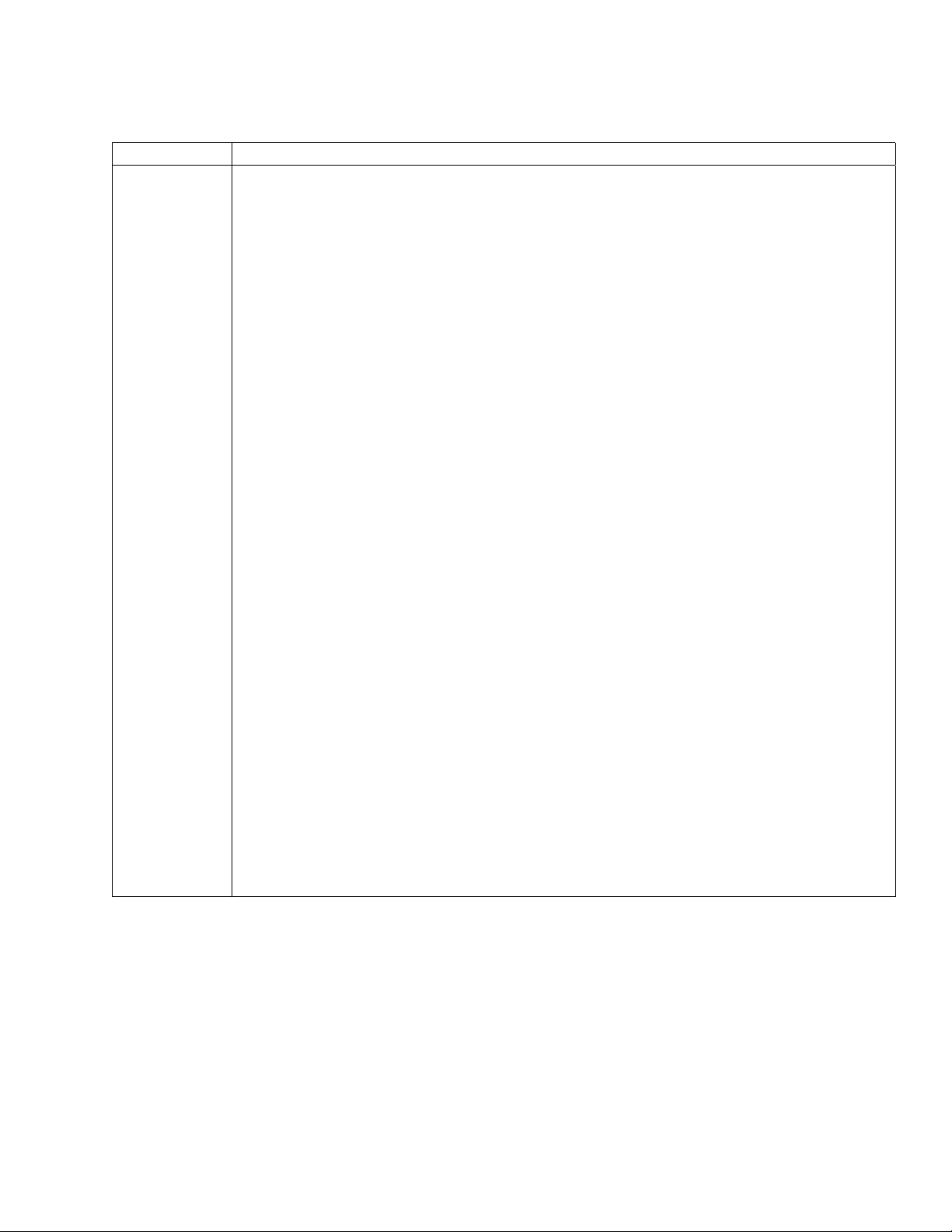
Figure 2-1 Default Character Set for ANSI Em ulati on, 00 to 7F
7265 Programmer’s Manual
Copyright © 2004 TallyGenicom
5
Page 10
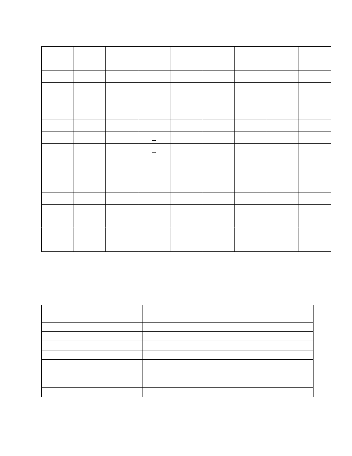
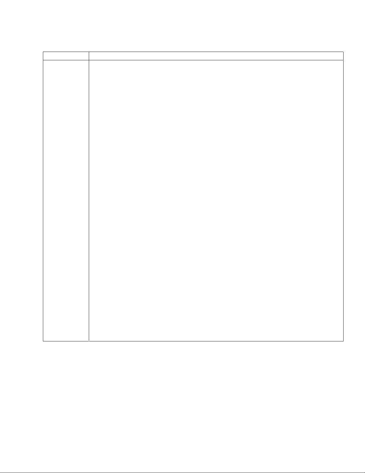
Code is Hexadecimal, Ordered Column|Row
89ABCDEF
0 DCS á
1 PU1 í
2ó
3ú
4 IND ñ
5 NEL Ñ
6a
7o
8 HTS ¿
9
A VTS
B PLD CSI
C PLU ST
D RI OSC
AB CD
¬ EFG
½ IJK
¼ MN Oæ P
¡ QR Sز
!"#
%& '
()*
,-#
/01
345
789
:;<
>?@
$
±
+
.
2
6
÷
=
º
•
H
L
E
F
« TUVW
» XYZ[
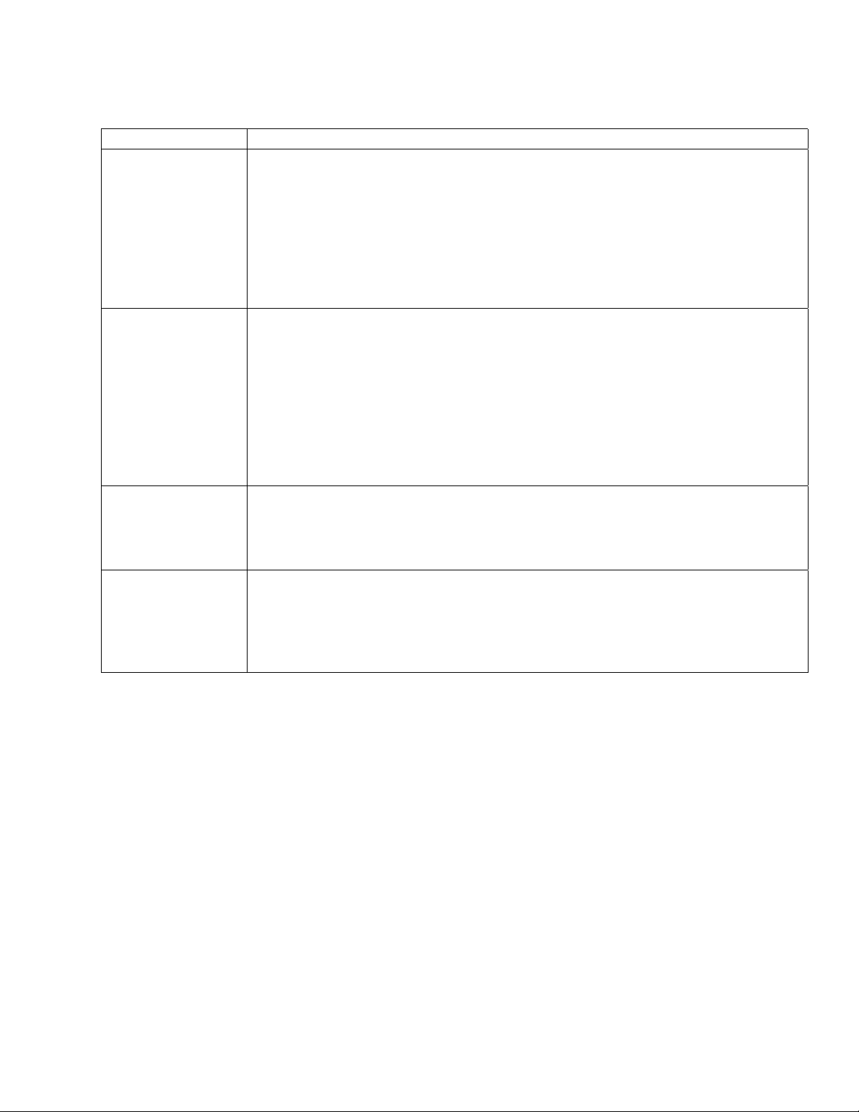
Figure 2-2 Default Character Set for ANSI Emulation, 80 to FF
Escape Sequence Summary
In this chart, the 7-bit representation is given. Use the Comparison Chart on page 4 to convert
7 bit to 8 bit sequences.
Code Description
ESC H Set Horizontal Tab
ESC J Set Vertical Tab
ESC K Subscript Printing
ESC L Superscript Printing
ESC P Enter Dot Graphics
ESC c Restore to Initial State
ESC \ Exit Dot Graphics Modes
ESC [(p1);(p2)<SP>B Graphic Size Modification
ESC [(p1);(p2)<SP>G Line/Character Spacing
!
7265 Programmer’s Manual
Copyright © 2004 TallyGenicom Chapter 2 ANSI
6
Page 11
Code Description
ESC [(p1);(p2)<SP>~ Select Emulation
ESC [(p)` Horizontal Position Absolute
ESC [(p)a Horizontal Position Relative
ESC [(p)d Vertical Position Absolute
ESC [(p)e Vertical Position Relative
ESC [(p1);(p2)f Vertical and Horizontal Position Absolute
ESC [(Ps)g Clear Tabs
ESC [(p1);...(pn)h Set Auto CR on LF
ESC [>(p1);...(pn)h Set Mode (GENICOM)
ESC [(p)j Horizontal Position Backwards
ESC [(p)k Vertical Position Backwards
ESC [(p1);...(pn)l Reset Auto CR on LF
ESC [>(p1);...(pn)l Reset Mode (GENICOM)
ESC [(P1);...(Pn)m Fonts and Print Modes (SGR)
ESC [(p1)p Select Paper Path
ESC [(p1)q Select Graphics Density
ESC [(p1);(p2);(p3)r Forms Setup
ESC [(p1);(p2)s Sets Left and Right Margins
ESC [(p1)t ENA/DIS Oversized/Expanded/Bar Code
ESC [(p1);(p2);...(p22)u Set Horizontal Tabs at Certain Positions
ESC [(p1);(p2);...(p12)v Set Vertical Tabs at Certain Positions
ESC [(p1);(p2);…} Set Bar Code Parameters
ESC [(p)x National Character Sets
7265 Programmer’
Copyright © 2004 TallyGenicomenico Chapter 2 ANSI
Manual 7
Page 12
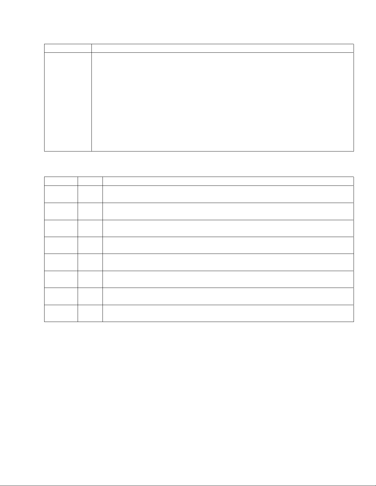
Pr inter Handshaking
Commands Description
DC1 PRINTER READY
In serial interface, if the printer is strapped for XON/XOFF handshaking, then
the printer sends DC1 to the host to signal that the printer is ready to accept
data.
In parallel interface, if the printer is strapped for select/ deselect by received
DC1/DC3 codes, then the host sends DC1 to the printer to set the printer
online.
Dec 17 Hex 11
DC3 PRINTER NOT READY
In serial interface, if the printer is strapped for XON/XOFF handshaking, then
the printer sends DC3 to the host to signal that the printer cannot, for the
moment, accept any more data.
In parallel interface, if the printer is strapped for select/ deselect by received
DC1/DC3 codes, then the host sends DC3 to the printer to set the printer to
Standby. In Standby, the printer will accept and acknowledge data from the
interface, but will discard all data received.
Dec 19 Hex 13
ETX ETX/ACK COMMUNICATION PROTOCOL
In serial interface, if the printer is strapped for ETX/ACK handshaking, then the
host sends the ETX control code at the end of a block of data.
Dec 3 Hex 03
ACK ETX/ACK COMMUNICATION PROTOCOL
In serial interface, if the printer is strapped for ETX/ACK handshaking, then the
printer sends an ACK in response to and ETX from the host to indicate that it is
ready to receive more data.
Dec 6 Hex 06
7265 Programmer’s Manual
Copyright © 2004 TallyGenicom Chapter 2 ANSI
8
Page 13
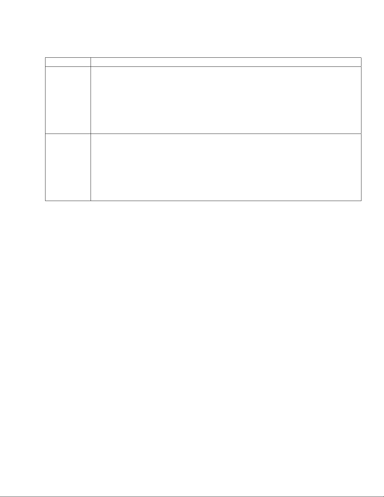
Printer Control
Commands Description
SO SHIFT OUT
You can strap the printer to start either barcode (page 37) or oversized (page 64)
mode, whichever is enabled, on receipt of SO. The ISU status of SO/SI control is
disabled. You can enable SO/SI control from Software Options on the printed menu,
or from the host via the Straps and Options control sequence. See page 14.
Dec 14 Hex 0E
SI SHIFT IN
If the printer is strapped to turn on barcode or oversized on receipt of SO, then SI
turns barcode (page 37) or oversized (page 64) mode off.
Dec 15 Hex 0F
ESC ESCAPE
Introduces an escape sequence. The printer evaluates characters following the ESC
character to determine if the sequence is valid. If the sequence is valid, then the
printer responds to the command. If the sequence is not valid, then the printer aborts
the process, discarding at least the first character following ESC.
Dec 27 Hex 1B
ESC P
(DCS)
ESC [
(CSI)
ESC \
(ST)
ESC ]
(OSC)
DEVICE CONTROL STRING
The control function introducer for the device control string structure, which is used to
frame graphics.
Dec 144 Hex 90
The CSI character is the control function introducer for the ANSI control sequence.
Control sequences are multi-character control functions that accept parameters.
Dec 155 Hex 9B
STRING TERMINATOR
Terminates the DCS and the OSC sequence.
Dec 156 Hex 9C
The OSC character is the introducer for straps and options.
Dec 157 Hex 9D
BEL BEEPER
Dec 7 Hex 07
9
7265 Programmer’s Manual
Copyright © 2004 TallyGenicom Chapter 2 ANSI
Page 14
Commands Description
DEL DELETE
DEL is a printable character, or is a valid graphics data byte if received
in dot graphics
Dec 127 Hex 7F
ESC [(p1);
(p2)<SP>~
SELECT EMULATION
If p2 is 0, which is the default, then the current settings in the printer remain in effect
through the emulation change to the extent that selected features are supported in
the target emulation. This affects such things as, font selection, character pitch,
margins, tabs, and so forth. If p2 is 1, then the status of such parameters reverts to
defaults dependent on the selected emulation.
p1 selects
0 GENICOM ANSI
1 Tally ANSI
2-21 Reserved
22 Epson FX286e
mode.
p2 selects
0-1 full reset
Example: Select Epson emulation with full reset:
Dec 27 91 50 50 59 49 32 126 Hex 1B 5B 32 32 3B 31 20 7E
ESC [(p1)p SELECT PAPER PATH
p1 selects
08 unload current path
10 unload current path and load tractor 2
12 unload current path and load tractor 1
Forms in the current path should be torn off before changing paper paths. If
you send a command to change paper paths and there is more paper
downstream of the print head than 1/2 times the current form length or six
inches, whichever is greater, then the printer returns paper to the position that
was current before the command was received, and a fault condition is set.
If you send a command to change paper paths and the target path is the
current path, then the printer executes a form feed. If you load tractor 2
when tractor 2 is not installed, the command will be ignored.
Example: Unload tractor 1 and load tractor 2:
Dec 27 91 49 48 112 Hex 1B 5B 31 30 70
7265 Programmer’s Manual
Copyright © 2004 TallyGenicom Chapter 2 ANSI
10
Page 15
Commands Description
ESC c RESET TO INITIAL STATE
Recalls the user format presently assigned to the current paper path.
Dec 27 99 Hex 1B 63
ESC [(p1)t ENABLE/DISABLE OVERSIZED/EXPANDED/BAR CODE MODES
p1 Effect Page
0 reset special modes
1 select oversized printing 4-2
2 select expanded printing 4-2
3 select bar code 3-6
Oversized printing and bar codes are explained in separate chapters. When
expanded printing is selected, the current font is expanded horizontally and vertically
in 100% increments according to expansion factors specified by ESC
[(p1);(p2)<SP>B (see page 11). The range of expansion is 1x through 8x.
Example: select expanded printing
Dec 27 91 50 116 Hex 1B 5B 32 74
ESC [(p1);
(p2)<SP>B
GRAPHIC SIZE MODIFICATION
Sets the size of expanded and oversized characters. The effect of this command on
oversized is explained in a separate chapter.
When expanded print is selected, the argument units for parameters p1 and p2 are
percentages of the vertical and horizontal dimensions of the current font. Parameter
p1 controls the vertical expansion and p2 controls the horizontal expansion. The
argument limits for expanded print are 800;800 (8x the parent font size).
Oversized enables much larger expansions. Parameters are rounded down to the
nearest 100.
Note: This printer goes into expanded mode immediately on receiving this
command. Any text between this sequence and a countermanding ESC [(p1)t
sequence (see page 11) is printed according to the specified expansion.
If height and width are different values, the height will be set the same as the width.
ESC [(p1);
...(pn)h
SET MODE (ANSI)
p Effect
20 auto CR on LF
Dec 27 91 50 48 104 Hex 1B 5B 32 30 68
7265 Programmer’s Manual
Copyright © 2004 TallyGenicom Chapter 2 ANSI
11
Page 16
Commands Description
ESC [(p1);
...(pn)l
RESET MODE (ANSI)
Resets mode(s) set by ESC [(p1);..(pn)h.
p Effect
20 reset auto CR on LF
Example: reset auto CR on LF
Dec 27 91 50 48 108 Hex 1B 5B 32 30 6C
ESC [>
(p1);..(pn)h
ESC [>
(p1);..(pn)l
SET MODE (GENICOM)
This is an ANSI private use sequence.
p Effect
1 proportional print
2 reserved
3 80 hex - 9B hex interpreted as C1 control codes
4 bold mode accomplished by overstrike
5 select character set 2
Example: set proportional print
Dec 27 91 62 49 104 Hex 1B 5B 3E 31 68
RESET MODE (GENICOM)
Resets modes set by ESC [>(pn)h. See the previous command. The parameter
definitions are the same.
Example: reset proportional print
Dec 27 91 62 49 108 Hex 1B 5B 3E 31 6C
7265 Programmer’s Manual
Copyright © 2004 TallyGenicom Chapter 2 ANSI
12
Page 17
Commands Description
ESC [(p1);
(p2);<SP>{
PAPER SHEAR
If the paper shear option is installed, then note that the appropriate strap must be set
in the hardware options menu in order for the paper shear to work.
Parameter p1 = 1 selects the paper shear.
Parameter p2 = 1 executes a cutting sequence: If the vertical position is not at top-of-
form, then a form feed is executed. Paper is advanced to the shear position and cut.
Next, it is advanced an inch to eject the sheet that has been cut off; then it is
retracted to the top margin on the following form. The horizontal position following a
shear is the left margin. The shear position should be set from the control panel so
that paper is cut precisely at the perforation. If a non-zero top print reference is
needed, then set the top print reference first and then set the shear position.
Dec 27 91 49 59 49 32 123 Hex 1B 5B 31 3B 31 20 7B
7265 Programmer’s Manual
Copyright © 2004 TallyGenicom Chapter 2 ANSI
13
Page 18
Commands Description
ESC ]6;4;
(p3);(p4)
ESC \
STRAPS AND OPTIONS
This command enables downline control of options found at various places in the
printer menus. This includes the Emulation and Software Options menus, as well as
the User-defined Options menu. For details and descriptions, see the User’s
Manual.
p3 = 0 reset
1set
p4 =
4 auto cr on lf
5 auto lf on cr
6 auto cr on vt
14 auto wrap
7265 Programmer’s Manual
Copyright © 2004 TallyGenicom Chapter 2 ANSI
14
Page 19
Graphics Rendition (Fonts and Modes)
Command Description
ESC [(p1);
...(pn)m
SELECT GRAPHICS RENDITION
Selects print modes and fonts.
p1 Printing Mode
0 normal printing - resets all modes (but does not affect font selection)
1 set bold print
4 set underline
5 set doublewide
6 set proportional
*
10 and 11 Gothic DP
12 Gothic LQ
13 Courier DP
14 Courier LQ
15 Gothic Italic DP
16 Gothic Italic LQ
17 Courier Italic DP
18 Courier Italic LQ
19 Wide Gothic DP
*
22 cancel bold
24 cancel underline
25 cancel doublewide / expanded
26 cancel proportional
30 select black ribbon color
31 select red ribbon color
32 select green ribbon color
33 select yellow ribbon color
34 select blue ribbon color
35 select magenta ribbon color
36 select cyan ribbon color
7265 Programmer’s Manual
Copyright © 2004 TallyGenicom Chapter 2 ANSI
15
Page 20
NATIONAL CHARACTER SET
Command Description
ESC [(p)x SELECT NATIONAL CHARACTER SET
p Character Set
0 USA
1 Germany
2 French A
6 Italian
7 United Kingdom
8 Spanish
9 Danish/Norwegian A
16 Swedish/Finnish D
If a parameter value (p) is not recognized, then the default character set (0 - USA) is
selected.
To use substitutions that have characters in the 80 hex to 95 hex range, first disable
8-bit control code processing, either by escape sequence or from the Emulation
Options Menu. Next, enable character set 2, either by the Straps and Options control
sequence on page 14 or from the Emulation Options menu. This causes ASCII
codes 80 hex - 9F hex to be mapped to printable characters instead of control codes.
Example: To select the United Kingdom character set:
Dec 27 91 55 120 Hex 1B 5B 37 78
7265 Programmer’s Manual
Copyright © 2004 TallyGenicom Chapter 2 ANSI
16
Page 21
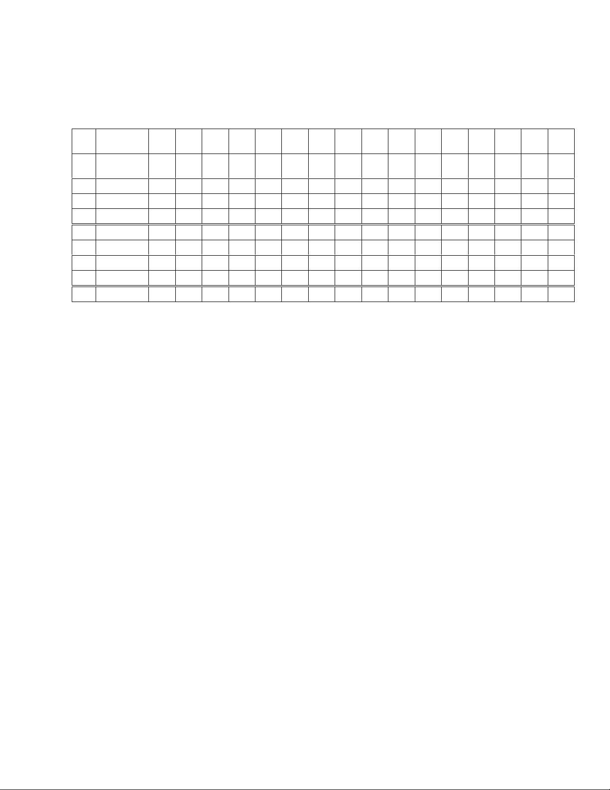
D/N = Danish/Norwegian S/F = Swedish/Finnish
Code D
Location H352336243826422A6440915B925C935D945E9660
Character
p
Set
0USA
1Germany
2 French A
6Italian
7UK
8 Spanish
9D/N A
16 Swedish
#$&* @[ \ ] ^` {
#$&* §ÄÖÜ^` äöüߢ¥
£$&* à° ç§^` éùè¨ ¢¥
£
$&*
£
$&*@[\]^`{
^
$&* @í Ñ¿^` ¨ ñ} ~¢¥
§°ç é
#$&* @ÆØÅ^` æøå~¢¥
¤
&*
É
ÄÖÅ
^
Üé
1237B1247C1257D1267E1559B157
!
}~¢¥
ùàòè ì
!
}~¢¥
¢¥
äöåü¢¥
9C
Figure 2-3 National Character Substitutions 0 - 18
7265 Programmer’s Manual
Copyright © 2004 TallyGenicom Chapter 2 ANSI
17
Page 22
Line/Character Spacing
Command Description
ESC [(p1); (p2)
<SP> G
LINE/CHARACTER SPACING
Sets the vertical and horizontal pitch in decipoints. Parameter (p1) is the
spacing between lines and (p2) is the spacing between characters.
Unspecified parameters remain at their current values. This command
does not affect oversized printing selected by ESC [1t.
7265 Programmer’s Manual
Copyright © 2004 TallyGenicom Chapter 2 ANSI
18
Page 23
Commands Description
ESC [(p1);
(p2) <SP> G
LINE/CHARACTER SPACING
p1 = line spacing parameter p2 = character spacing parameter
If you select doublewide printing (ESC [5m), then the printer doubles character
spacing set by this command. If the designed pitch of the current font is 10 cpi and
doublewide is set, then a character spacing argument of 72 results in a pitch of 5 cpi,
at which horizontal segments of line-draw characters are contiguous.
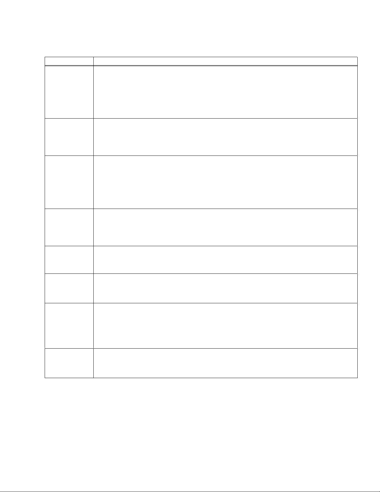
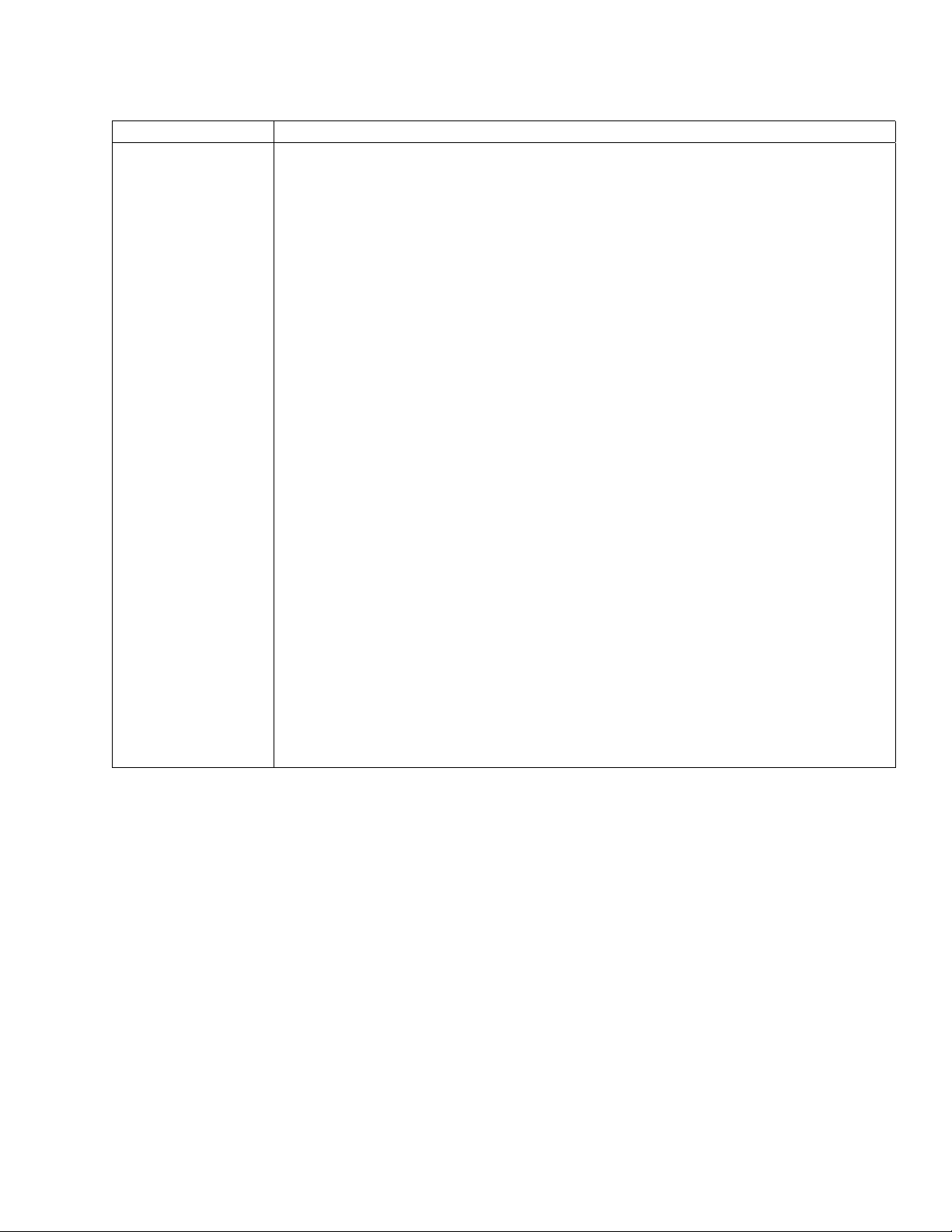
Example: ESC [90;60 <sp> G
sets the vertical spacing to 8 lines per inch and the horizontal spacing to 12
characters per inch. (720 divided by 8 = 90, and 720 divided by 12 = 60).
Dec 27 91 52 48 59 54 48 32 71
Hex 1B 5B 39 30 3B 36 30 20 47
p2 CPI
120 6
The quick brown fox jumped
90 8
72 10
60 12
51 14
45 16
40 18
36 20
The quick brown fox jumped over
The quick brown fox jumped over the lazy
The quick brown fox jumped over the lazy dog’s back.
The quick brown fox jumped over the lazy dog’s back.
The quick brown fox jumped over the lazy dog’s back.
The quick brown fox jumped over the lazy dog’s back.
The quick brown fox jumped over the lazy dog’s back.
Figure 2-4 Effects of Character Spacing Parameters
7265 Programmer’s Manual
Copyright © 2004 TallyGenicom Chapter 2 ANSI
19
Page 24

Forms Setup
Command Description
ESC [(p1);
(p2);(p3);(p4)
;(p5)r
FORMS SETUP
Sets top of form and sets form length, as well as top and bottom margins, in decipoints.
Parameter
p1 is form length 720ths ,
p2 is the top margin,
p3 sets the length of white space between the baseline of the last allowed
line and the end of form.
p4 is the top print reference, and
p5 is the left print reference
Any parameter not specified is assigned its default value. Maximum form length is
15840 decipoints (22 inches).
Default Values
p1 7920 decipoints 11-inch form
p2 0 decipoints 0-inch top margin
p3 0 decipoints 0-inch bottom margin
p4 0 decipoints 0-inch top print reference
p5 0 decipoints 0-inch left print reference
Example:
Set 8-inch form length, one-inch top margin, one-inch bottom margin
Dec 27 91 53 55 54 48 59 55 50 48 59 55 50 48 114
Hex 1B 5B 35 37 36 30 3B 37 32 30 3B 37 32 30 72
Note: Before you send this command, verify that the top print reference is zero in the
target paper path. One way to do this is to park and then load paper in the target path.
The top edge of the paper should line up with the top of the print head. If not, then set
the top print reference to zero from the menu and save the change to the format
associated with the target paper path. You must once again park and load paper in the
target path in order for the new print reference to take effect.
Next, send a command to set the vertical position-absolute to zero. If you do not do
this, then the printer establishes top-of-form at the current top margin, and form
registration is lost.
7265 Programmer’s Manual
Copyright © 2004 TallyGenicom Chapter 2 ANSI
20
Page 25
Superscript/Subscript
Command Description
ESC K
(PLD)
ESC L
(PLU)
NOTE: The partial line up does not respect top of form; that is, following a form feed, ESC L causes a partial line
movement upward. Also, partial line down does not respect bottom of form; that is, when printing the last line on
the form, ESC L causes a partial line movement downward.
SUBSCRIPT PRINTING
Moves paper 1/2 line below the current line for subscript printing. ESC K is used to
return to the original line following ESC L (superscript).
If 8-bit control code processing is enabled then
Dec 139 Hex 8B
otherwise
Dec 27 75 Hex 1B 4B
SUPERSCRIPT PRINTING
Moves paper 1/2 line above the current line for superscript printing. ESC L is used to
return to the original line following ESC K (subscript).
If 8-bit control code processing is enabled then
Dec 140 Hex 8C
otherwise
Dec 27 76 Hex 1B 4C
When printing the last line on a form, do not send a line feed (LF) code to move directly from superscript to
subscript. The LF code will be acted upon as the bottom of form terminator.
7265 Programmer’s Manual
Copyright © 2004 TallyGenicom Chapter 2 ANSI
21
Page 26
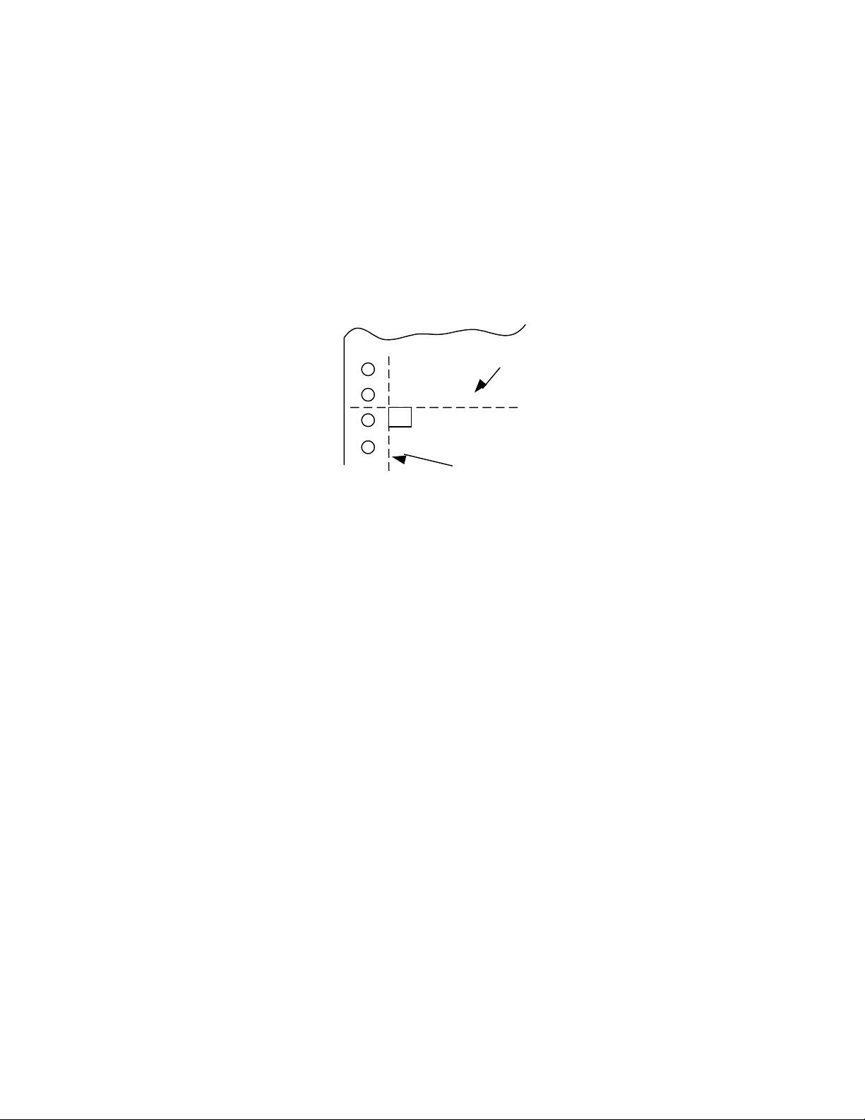
Vertical Movement
p
Absolute positions are calculated from the top and left print references without respect to margin
settings. The top of a character cell located at vertical position-absolute 0 is at top print reference.
The left edge of a character cell located at horizontal position-absolute 0 is at the left print
reference. If the default left print reference is current, and if the left tractor position(s) are as
shipped, then this is about 0.6 inches from the left edge of the paper.
Top and left print references are adjustable from the printer menu.
To
Shee
A
Extreme
Left Position
Character Printed at Zero Position
CAUTION: Do not attempt reverse paper motion across a perforation, since this may cause the
paper to snag on the print head. Vertical position accuracy is not specified for reverse paper
moves greater than 1.5 inches.
7265 Programmer’s Manual
Copyright © 2004 TallyGenicom Chapter 2 ANSI
22
Page 27
Vertical Movement
Commands Description
LF LINE FEED
Advances the paper one line according to the spacing currently in effect.
Dec 10 Hex 0A
VT VERTICAL TAB
Advances paper to the next vertical tab setting. If the current print position is at or
beyond the last tab setting, the paper advances to the top of form. If no tabs are set,
then VT is processed according to the status of emulation option strap 14.
Dec 11 Hex 0B
FF FORM FEED
Advances the paper to the top margin on the next form.
Dec 12 Hex 0C
ESC D
(IND)
ESC E
(NEL)
ESC M
(RI)
INDEX
Advances the paper to the next line. The current column is not changed, regardless
of the status of auto CR on LF.
Dec 132 Hex 84
NEXT LINE
The next line character advances the paper to the next line. The current column is
reset to the left margin. Auto CR on LF has no effect.
Dec 133 Hex 85
REVERSE INDEX
Moves the paper back one line.
Dec 141 Hex 8D
7265 Programmer’s Manual
Copyright © 2004 TallyGenicom Chapter 2 ANSI
23
Page 28
Commands Description
ESC [(p)e VERTICAL POSITION RELATIVE
Advances paper p decipoints. This command enables printing below the bottom
margin of the current form and above the top margin of the following form. The
example below advances the paper 4 1/4 inches.
Example: ESC [3060e
Dec 27 91 51 48 54 48 101 Hex 1B 5B 33 30 36 30 65
ESC [(p)k VERTICAL POSITION BACKWARDS
Moves the vertical position backwards to (p) decipoints above the current position.
The horizontal position does not change.
If the target position is above the top margin, then the vertical position is the top
margin. If no top margin is set, and the target position is above top-of-form, then the
vertical position is top-of-form.
NOTE: The printer economizes vertical motion with vertical logic seeking, so this
command may cause reverse paper motion in some instances and not in others.
Reverse paper motion can cause problems with some forms.
Example: ESC [1080k moves the vertical position up by 1.5 inches.
Dec 27 91 49 48 56 48 107 Hex 1B 5B 31 30 38 30 6B
ESC [(p)d VERTICAL POSITION ABSOLUTE
Moves the current print position to p decipoints from the top of the form.
The following example advances the paper to 2 inches below top of form.
Example: ESC [1440d
Dec 27 91 49 52 52 48 100 Hex 1B 5B 31 34 34 30 64
ESC[(p1);
(p2)f
VERTICAL AND HORIZONTAL POSITION ABSOLUTE
Moves the print position to any coordinate on the page. Coordinates are measured
in decipoints. Parameter p1 is the vertical coordinate, which is measured from the
top print reference. Parameter p2 is the horizontal coordinate, which is measured
from the left print reference. The computation of absolute positions is not influenced
by margin settings. Top and left print references are adjustable from the control
panel.
You can print characters beyond the left, top, and bottom margin setting, but no
printing is allowed beyond the right margin.
EXAMPLE: ESC [1440;2160f
Prints the next character 2 inches from the top print reference and 3 inches from the
left print ref erence.
Dec 27 91 49 52 52 48 59 50 49 54 48 102
Hex 1B 5B 31 34 34 30 3B 32 31 36 30 66
7265 Programmer’s Manual
Copyright © 2004 TallyGenicom Chapter 2 ANSI
24
Page 29
Margins
Use the Forms Setup command, page 2-39, to set vertical margins.
Commands Description
ESC [(p1);6 (p2)s SET LEFT AND RIGHT MARGIN
Sets the left and right margin in decipoints; p1 is the left margin and p2 is the
right. Distances are measured from the left print reference. This command
takes effect following the next line terminator (you cannot set margins for the
current line).
EXAMPLE: Set the left margin at 0.4 inch and right margin at 6.9 inches,
making a 6.5-inch print line.
Dec 27 91 50 56 56 59 52 57 54 56 115
Hex 1B 5B 32 38 38 3B 34 39 36 38 73
ESC [s ASSIGN MARGIN DEFAULTS
Assigns the default parameters. Sets the left margin to zero, right margin to
maximum print line width of the printer. This command takes effect following the
next line terminator.
Dec 27 91 115 Hex 1B 5B 73
7265 Programmer’s Manual
Copyright © 2004 TallyGenicom Chapter 2 ANSI
25
Page 30
Horizontal Movement
Commands Description
HT HORIZONTAL TAB
Causes the current print position to move to the next tab stop. If no tabs are set, then
the current position moves one space. If tab(s) are set but no tab(s) are set between
the active print position and the right margin, then following characters on the line are
either discarded or printed on the next line, depending on the status of auto wrap.
Dec 9 Hex 09
CR CARRIAGE RETURN
Initiates printing and returns the current print position to the left margin.
Dec 13 Hex 0D
ESC [(p)a HORIZONTAL POSITION RELATIVE
Advances the current print position by the distance specified. Parameter p is
specified in decipoints.
Example: ESC [1080a advances the print position 1.5 inches.
Dec 27 91 49 48 56 48 97 Hex 1B 5B 31 30 38 30 61
ESC [(p)j HORIZONTAL POSITION BACKWARDS
Moves the horizontal position (p) decipoints left of the current position.
Actual distance between symbols separated by this command is the argument (p)
minus the current horizontal pitch (text or graphics). For example, if you print an
uppercase E at 10 cpi, move backwards by (p), and print another uppercase E, then
the distance between leading edges of the two characters is (p) - 72 decipoints. If you
print graphics at 72 dpi, move backwards by p, and print another graphics column,
then the distance between the two graphics columns is (p) – 10 decipoints.
This command enables printing left of the left margin. Any data located left of the left
print reference is discarded.
Example: ESC [1080j moves the horizontal position back by 1.5 inches.
Dec 27 91 49 48 56 48 106 Hex 1B 5B 31 30 38 30 6A
7265 Programmer’s Manual 26
Copyright © 2004 TallyGenicom Chapter 2 ANSI
Page 31

Commands Description
ESC [(p)` HORIZONTAL POSITION ABSOLUTE
Causes the print position to move (in decipoints) a specified distance from the left
print reference.
Example: ESC [360` Move print head ½” from left print reference.
Dec 27 91 51 54 48 96 Hex 1B 5B 33 36 30 60
BS BACKSPACE
Prints the data in the print buffer, then moves the print position one character position
to the left.
Dec 8 Hex 08
7265 Programmer’s Manual
Copyright © 2004 TallyGenicom Chapter 2 ANSI
27
Page 32

Tabs
This printer stores tab stops in NVRAM while power is off. Therefore, all tab stops should be cleared before new
stops are set.
Commands Description
ESC H
(HTS)
ESC [(p1)
(p2);..(p22)u
ESC J
(VTS)
ESC [(p1);
(p2);.. (p12)v
ESC [(Ps)g CLEAR TABS
SET HORIZONTAL TAB AT CURRENT POSITION
If 8-bit control code processing is enabled then both
Dec 136 Hex 88
otherwise only
Dec 27 72 Hex 1B 48
SET HORIZONTAL TABS AT SPECIFIED POSITIONS
Sets up to 22 stops at one time. The value of p1, p2, etc. are in
decipoints (1 inch = 720 decipoints).
Dec 27 91 55 50 48 59 50 56 56 48 117
Hex 1B 5B 37 32 30 3B 32 38 38 30 75
The above example sets tabs at 1 inch and 4 inches. Existing tab stops ar e not
cleared. Margin settings have no effect on the positions of tab stops.
SET VERTICAL TAB AT CURRENT POSITION
If 8-bit control code processing is enabled then both
Dec 138 Hex 8A
otherwise only
Dec 27 74 Hex 1B 4A
SET VERTICAL TABS AT SPECIFIED POSITIONS
Sets vertical tabs at positions p1, p2, p3, etc. Up to 12 stops can be set at one
time. Tab stops are measured in decipoints from the top print reference.
Example: Set tab stops at 4 and 7 inches.
Dec 27 91 50 56 56 48 59 53 48 52 48 118
Hex 1B 5B 32 38 38 30 3B 35 30 34 30 76
Ps Effect
0 clear horizontal tab at current print position
1 clear vertical tab at current position
3 clear all horizontal tabs
4 clear all vertical tabs
Example: Clear all horizontal tabs
Dec 27 91 51 103 Hex 1B 5B 33 67
7265 Programmer’s Manual
Copyright © 2004 TallyGenicom Chapter 2 ANSI
28
Page 33

Dot Graphics
Dot graphics allows you to print individual dots at any position on the page and thus to print
pictures as well as text. When you enter dot graphics, the printer defaults to a dot density of 72
dpi horizontally and vertically, and a line spacing of 12 lpi. Exiting from dot graphics returns the
printer to its prior lpi setting. You can also choose a density of 144 dpih x 72 dpiv. The printer
powers up in low density. The density remains as last set until it is changed, or until power is
turned off.
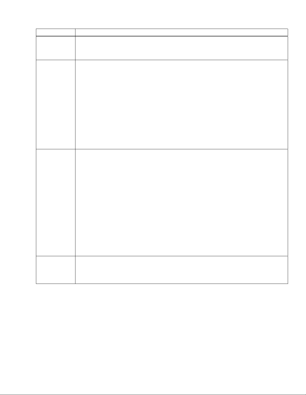
Each byte of graphics data defines one column of dots that is six dots high. You can think of the
least significant six bits in the byte as controlling the topmost six wires of the print head, with the
first bit controlling the top wire and the sixth bit controlling the sixth wire down. If you wanted to
fire all six wires, then you would send a byte with a decimal value of 63. Byte values of 0 through
31 decimal are interpreted as control codes, so you have to add 64 to any graphics data byte less
than 32 decimal.
You would expect to be able to simply add the value 64 decimal to every graphics data byte; in
other words, just set the seventh bit. This is risky because some variations within the 3000
product family interpret decimal 127, the Delete character, within a graphics sequence. The effect
is to delete everything following the last line terminator. The safest course is:
byte_val < 32 then byte_ val = byte_val + 64
WEIGHT WIRE
11
22
43
84
16 5
32 6
!!
!!
!!
!!!!!
!!
!
65 66 68 72 88 40 88 72 68 66 65
Figure 2-5 Dot Column Coding
7265 Programmer’s Manual
Copyright © 2004 TallyGenicom Chapter 2 ANSI
29
Page 34
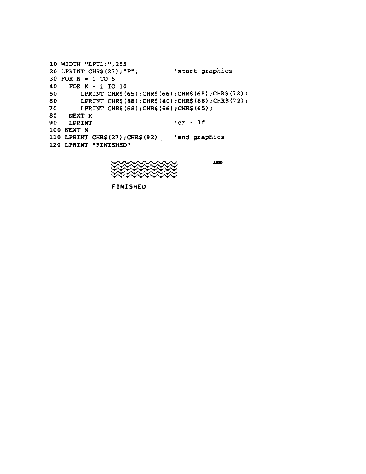
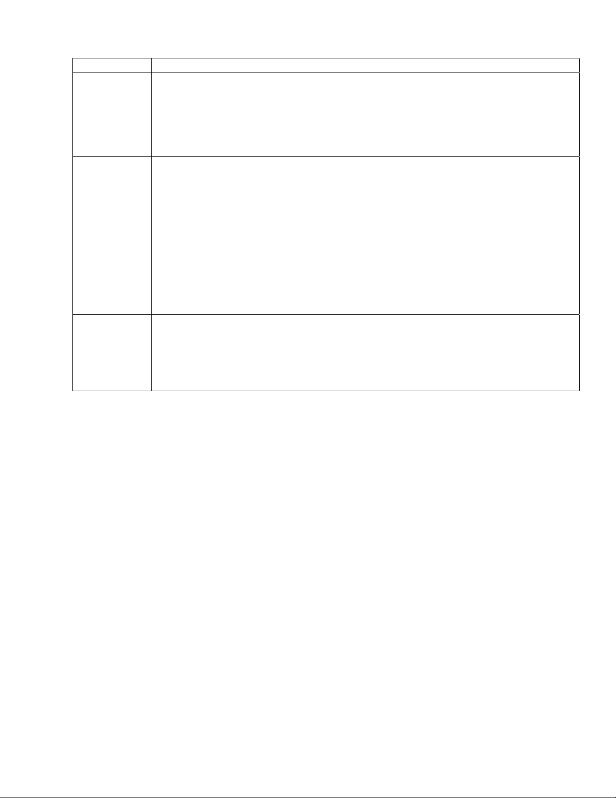
Sample Basic Program for Dot Coding
Figure 2-6
Dot Graphics Example
7265 Programmer’s Manual
Copyright © 2004 TallyGenicom Chapter 2 ANSI
30
Page 35

Graphics Control Functions
The set of control codes that are interpreted while in graphics mode are shown in the following
charts. Bytes less than 32 decimal that are not interpreted as control codes are ignored. The
printer processes valid escape sequences within a graphics data sequence. This is potentially
useful, for instance, in the cases of the absolute and relative position commands. A valid escape
sequence that is not applicable to graphics mode, such as bold printing mode, will be
implemented for text on exiting graphics. If the printer receives a nonvalid escape sequence while
in graphics mode, then it drops out of graphics mode.
Commands Description
BEL BELL
Causes the beeper to sound for about 1/2 second.
Dec 7 Hex 07
HT HORIZONTAL TAB
Causes the print head to move to the next tab stop.
Dec 9 Hex 09
LF
(NEL)
VT VERTICAL TAB
FF FO RM FEED
CR CARRIAGE RETURN
IND INDEX
RI REVERSE INDEX
ESC P ENTER DOT GRAPHICS MODE
ESC \ EXIT DOT GRAPHICS MODE
LINE FEED
Graphics next line. Causes printing to move to the left margin on the following line.
If 8-bit control code processing is enabled, then NExt Line does the same thing.
Dec 10 or 133 Hex 0A or 85
Causes printing to move to the left margin at the next vertical tab stop.
Dec 11 Hex 0B
Causes printing to move to the top left margin on the following form.
Dec 12 Hex 0C
Causes printing to move to the left margin on the current line. This permits
overprinting the current line.
Dec 13 Hex 0D
If 8-bit control code processing is enabled, then a line feed is performed at the
graphics vertical pitch. The horizontal position stays the same.
Dec 132 Hex 84
If 8-bit control code processing is enabled, then a reverse line feed is performed at
the graphics vertical pitch. The horizontal position stays the same.
Dec 141 Hex 8D
Also sets line spacing to 1/12 inch so that LF produces contiguous graphics lines.
Dec 27 80 Hex 1B 50
Also restores line spacing to its previously set value.
Dec 27 92 Hex 1B 5C
7265 Programmer’s Manual
Copyright © 2004 TallyGenicom Chapter 2 ANSI
31
Page 36

Commands Description
ESC [(p1)q GRAPHICS DENSITY
Sets the graphics density. The printer powers up with a graphics density of 72 x 72
dpi; changes are not stored in NVRAM.
p1 horizontal density vertical density
0 72 dpi 72 dpi
1 144 dpi 72 dpi
Dec 27 91 48 113 Hex 1B 5B 30 71
7265 Programmer’s Manual
Copyright © 2004 TallyGenicom Chapter 2 ANSI
32
Page 37

Chapter 3.
ANSI Bar Codes
This chapter describes the characteristics and lists ANSI control sequences for 23 resident bar
code styles. You have to be in ANSI emulation to print the resident bar codes. You can adjust
various bar code attributes including rotation, height, print density, status of the human-readable
line, and element widths. Subject to some constraints based on style and rotation, the humanreadable font is also selectable. For some styles, the printer will calculate checksum characters
for you.
To print a bar code symbol, you need to:
1) Set the printer to ANSI emulation.
2) Send the escape sequence to set the user-adjustable attributes. Always do this at least
once.
3) Send the control sequence to turn on bar code.
4) Send the ASCII representation of symbol data you want to encode.
5) Send the control sequence to turn off bar code.
6) Send a line terminator at some point thereafter.
In bar code parlance, a module is the narrowest nominal width of measure, while an element is a
single bar or space. A character is a group of elements that represents a number, letter, or
punctuation mark. A symbol is a group of characters that can stand alone in terms of being
interpreted by the reader. A symbol always comprises one or more data characters framed by
white spaces known as quiet zones. The symbol frame almost always includes start and stop
characters. Depending on the style, some bar code symbols can also include check characters,
center characters, and guard bars.
Among printers that generate bar codes internally and that also support any user-adjustment of
bar code widths, some enable the specification of module width, while others, such as this one,
enable the adjustment of element widths. From the programmer's point of view, adjustable
module widths tend to guarantee that the ratio among element widths remains correct, while
adjustable element widths afford more flexibility.
When we ship the printer, the ratios among element widths in a given bar code style are within
generic specifications for that style. You can restore these default element widths by performing
an initial setup (ISU) as described in the User's manual. Since this printer lets you specify
element widths independently of each other, it is possible to print bar codes that are outside of
generic specifications, or outside of the limits of your particular reading system, or both. You need
to know the requirements of your system before you program your printer.
Bar codes printed with this printer are suitable for readers designed for low- or medium-density
bar code symbols. Avoid readers with apertures smaller than 7 mils. If bar codes are to be read
with an infrared reader, then you must use a special carbon ribbon.
The examples given in this section use the Code 3-of-9 format.
7265 Programmer’s Manual
Copyright © 2004 TallyGenicom Chapter 3 ANSI Bar Codes
33
Page 38

Before You Begin - Set the Form Length
Programmers tend not to trust form feeds and sometimes use line feeds instead to move from
one form to another. If there is any advantage to that approach, it is that the vertical move will not
depend on the current form length. When printing bar codes on labels, you can greatly simplify
your task by setting a form length that exactly matches the length of your physical form and then
using form feeds to make vertical moves between labels or rows of labels.
If you print nothing but text, then the vertical position following each line feed lies on a grid that is
evenly spaced according to the line feed increment. If you print a bar code symbol, then positions
established by subsequent line feeds may not be on that grid. The vertical position following a bar
code symbol becomes the origin for a subsequent line feed; this new origin must be computed
based on bar code height, and the status of the human-readable line.
If you do not initialize your vertical position with a form feed for each row of labels, then printed
objects may creep cumulatively up or down with respect to the top of your physical form.
7265 Programmer’s Manual
Copyright © 2004 TallyGenicom Chapter 3 ANSI Bar Codes
34
Page 39

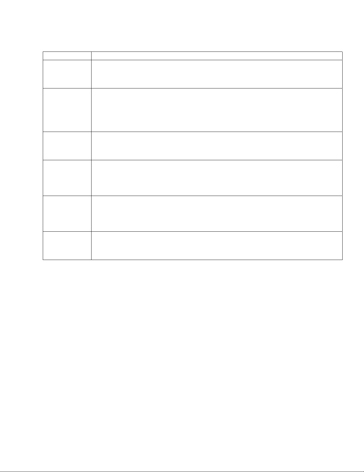
Setting Bar Code Parameters
The ANSI control sequence that sets bar code parameters has the format:
Command Description
ESC
[p1;p2;p3;p4;p
5;p6;p7;p8;p9;
p10;p11;p12;p
13}
Set Up Bar Code Parameters
Determines bar code parameters to be used when bar code mode is enabled.
See following sections.
Dec 27 91 (p1) 59 (p2) 59…(p13)125
Hex 1B 5B (p1) 3B (p2) 3B…(p13) 7D
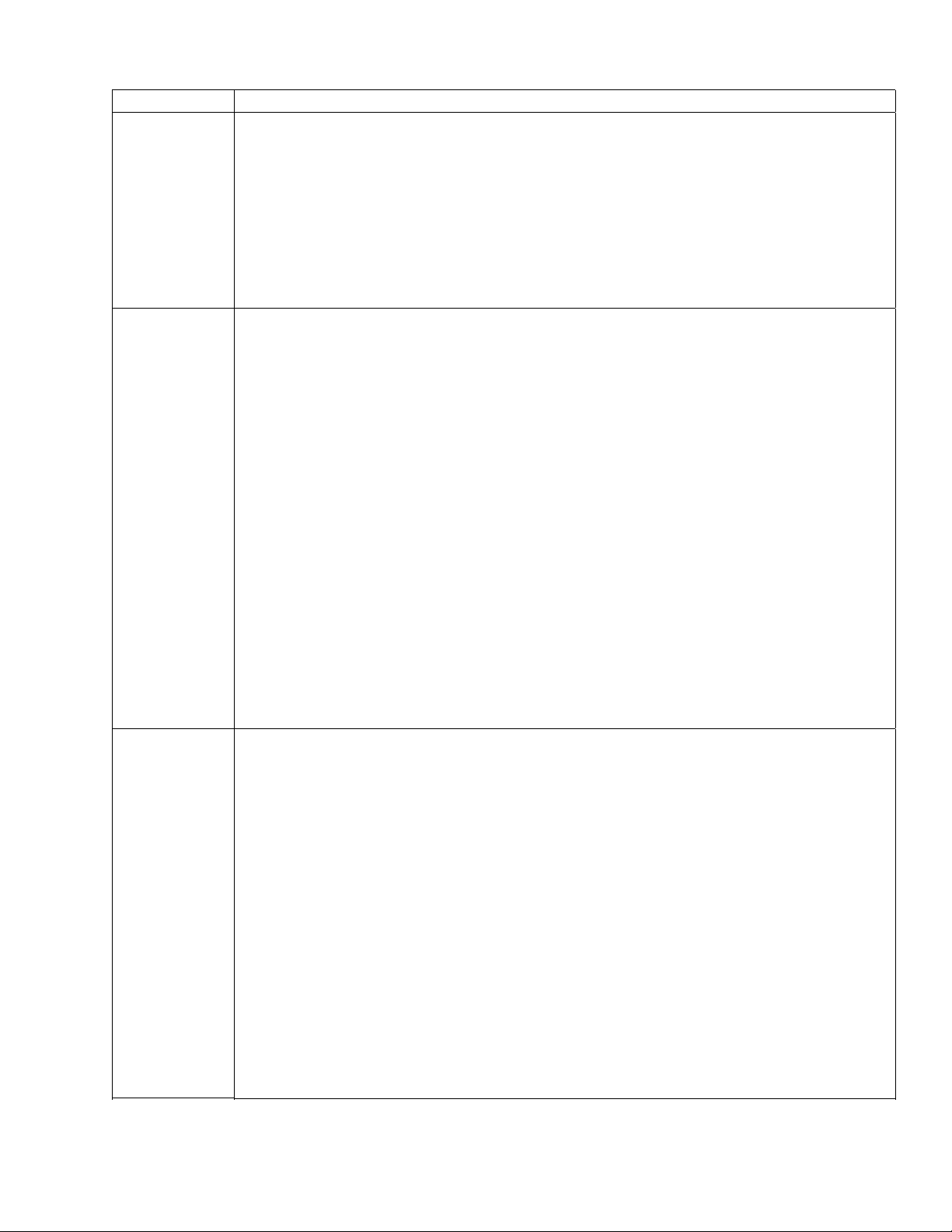
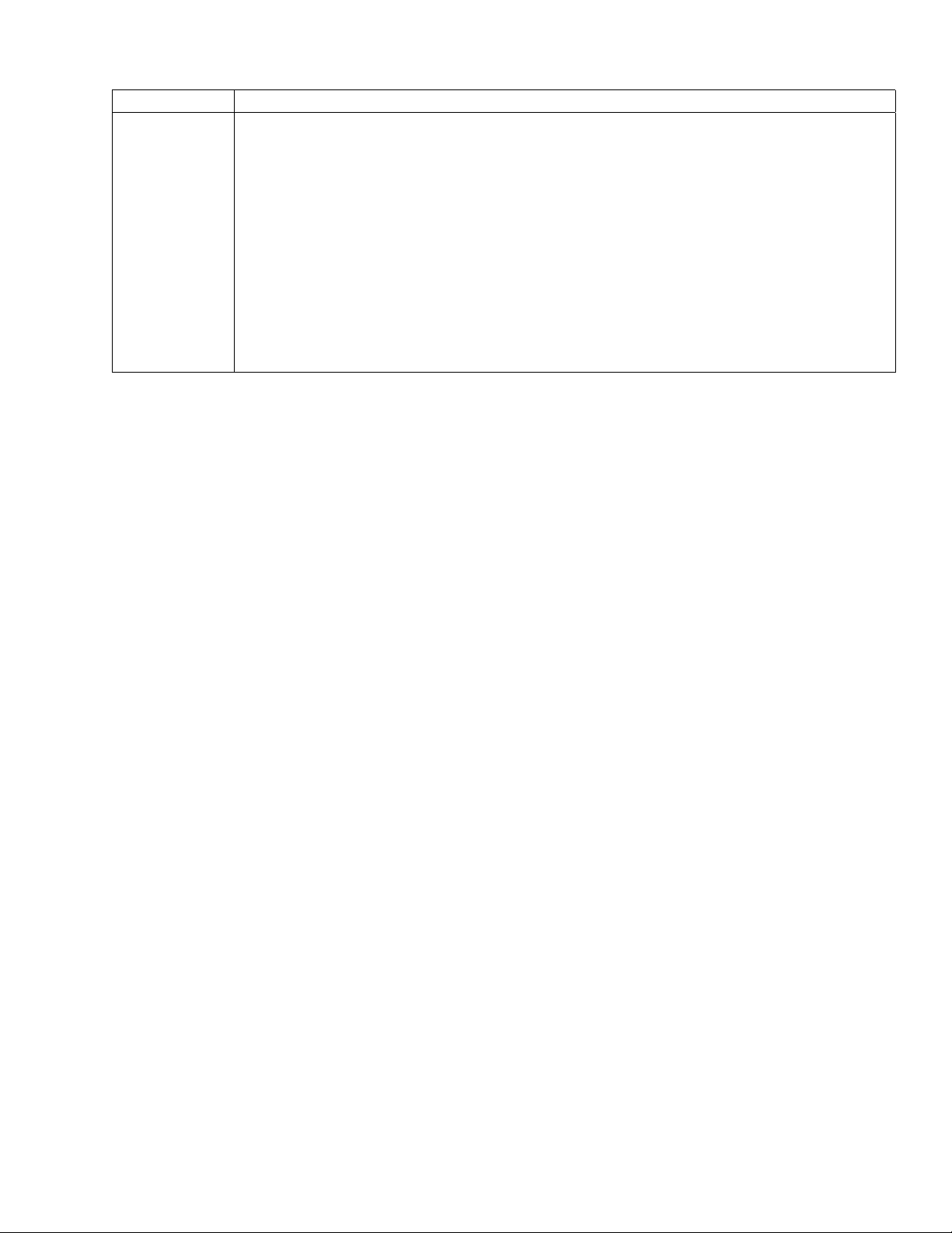
Bar Code Height
Parameter p2
0123456789
0123456789
01234567890123456789
0123456789
Human Readable
Line Parameter p3
Wide Bar Width
Parameter p5
Narrow Space
Width Parameter p6
Figure 3-1 Parts of a Bar Code
Narrow Bar Width
Parameter p4
Wide Space Width
Parameter p7
7265 Programmer’s Manual
Copyright © 2004 TallyGenicom Chapter 3 ANSI Bar Codes
35
Page 40

Values of all the adjustable bar code parameters are stored in NVRAM while power is off. You
can restore the bar code attributes to the factory settings by performing an ISU on the printer.
pn Attribute
p1 style
p2 height
p3 human readable line enable
p4 narrow bar width
p5 wide bar width
p6 narrow space width
p7 wide space width
p8 N / A
p9 rotation
p10 horizontal print density
p11 check character
p12 human readable font
p13 height (in 1/24” increments)
General Rules for Assigning Parameters
You can send the sequence to modify bar code parameters any time except when bar code
mode is active.
If you assign a parameter value outside the permissible range, then that parameter value
reverts to the default value.
Values for narrow bars must be less than values for wide bars. Values for narrow spaces
must be less than values for wide spaces. The ratio between wide and narrow elements
should be about 3:1.
As with other ANSI escape sequences that take multiple parameters, you can use the semicolon
as a place holder when you want to change a higher-numbered parameter while leaving lowernumbered parameters alone. For example, to set the horizontal print density to 60 dpi without
changing any other bar code attributes, you could send:
ESC [;;;;;;;;;0;;}
Semicolons that trail the last specified parameter are optional. For example, to turn off the
human-readable line without changing any other parameters, you could send:
ESC [;;0}
Or, you could send:
ESC [;;0;;;;;;;;;}
Note: The term “default” is misleading when applied to bar code parameters. This printer stores
bar code parameters in nonvolatile RAM while power is off; except for an ISU or an out-of-range
argument, you might never see the effects of the factory defaults. For this reason, your
application should probably initialize all 12 parameters one time before any symbols are sent.
This is particularly true when other bar code applications are sharing the printer.
7265 Programmer’s Manual
Copyright © 2004 TallyGenicom Chapter 3 ANSI Bar Codes
36
Page 41

Bar Code Command
Sequences
Command Description
ESC [3t ENABLE BAR CODES
Enables Bar Codes with the characteristics set by ESC [(p1);(p2)…}.
ESC [3t selects Bar Code mode and
activates Bar Code printing.
Dec 27 91 51 116 Hex 1B 5B 33 74
ESC [0t CANCEL OVERSIZED/EXPANDED/BAR CODE MODES
Dec 27 91 48 116 Hex 1B 5B 30 74
SO
SHIFT OUT
Turns off bar code printing, then enters bar code mode again.
Dec 14 Hex 0E
SI
SHIFT IN
SI
turns bar code printing off.
Dec 15 Hex 0F
7265 Programmer’s Manual 37
Copyright © 2004 TallyGenicom Chapter 3 ANSI Bar Codes
Page 42

p1 - Bar Code Style
This printer supports the following styles:
p1 Style
0 Interleaved 2 of 5
1 Bidirectional 2 of 5
2 Matrix 2 of 5
3 Industrial 2 of 5
4 Code 3 of 9 (default)
5 EAN-8
6 EAN-13
7 Code 11
9 Codabar a/t (see note)
10 Codabar b/n (see note)
11 Codabar c/* (see note)
12 Codabar d/e (see note)
13 UPC-A
14 UPC-E
15 Code 93
16 Code 128 (subsets A, B, and C)
17 Reserved
18 Reserved
19 MSI
p2 – Height
50 POSTNET
Note: Each of the four Codabar styles will accept any combination of valid start-stop characters
that you send. If you do not send any start-stop characters, then the printer generates start-stop
characters according to the style in force.
Height of the bar code in 1/12-inch increments. The default is ¾ inch, which corresponds to an
argument of 9.
Caution: In some versions of the printer, the last non-zero value of p13 supplants all subsequent
values of p2 until you ISU that printer. (See page 41.)
7265 Programmer’s Manual 38
Copyright © 2004 TallyGenicom Chapter 3 ANSI Bar Codes
Page 43

p3 - Human Readable Enable
An argument of 1 turns on the human-readable line, while 0 turns it off. The default is on. When
the human readable line is enabled, it is printed in the font specified by parameter p12. There is
0.1" between the bottom edge of the bar code and the top of the characters in the human-
readable line.
Element Widths
The default element widths are the narrowest that we recommend for consistent readability.
The argument units for horizontal bar code element widths are 1/120 inch. The print wire diameter
is 1/72 inch; a printed dot is about 1/60 inch in diameter. This is the finest line that the printer can
make. The printer accepts an element width of 1 as a valid argument, but the actual width of the
resulting element is 1/60 inch, the same as if you had specified a width of 2.
If the element width argument is greater than 2, then the printer rounds down odd numbers. A
width argument of 5 produces the same result as a width argument of 4.
p4 - Narrow Bar Width
Argument units are 1/120 inch if the bar code is horizontal (0o or 180o rotation) or 1/144 inch if the
bar code is vertical (90
p5 - Wide Bar Width
Argument units are 1/120-inch increments if the bar code is horizontal or 1/144 inch if the bar
code is vertical. The default is 6.
p6 - Narrow Space Width
Argument units are 1/120-inch increments if the bar code is horizontal or 1/144 inch if the bar
code is vertical. The default is 2.
p7 - Wide Space Width
Argument units are 1/120-inch increments if the bar code is horizontal or 1/144 inch if the bar
code is vertical. The default is 6.
Wide space and wide bar are both set to the smaller of the two values. This sets the proportion
of the large to small the same for spaces as it is for bars.
o
or 270o rotation). The default is 2.
7265 Programmer’s Manual
Copyright © 2004 TallyGenicom Chapter 3 ANSI Bar Codes
39
Page 44

Other Parameters
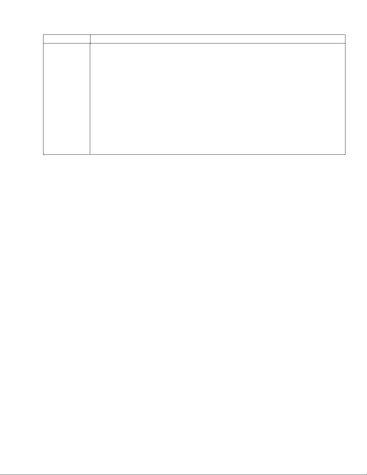
p9 – Rotation
Sets the absolute rotation in 90 degree increments. If parameter p12 = 0, then the humanreadable font is shown in the following table:
p9 Rotation HR Font if p12 = 0
0 no rotation (default) current font
1 no r otat ion special bar code HR font
2o270 rotation special bar code HR font
3 no rotation special bar code HR font
4 270o rotation special bar code HR font
Rotation 0
*1234*
1234
*1234*
1234
Rotation 1
*1234*
1234
Rotation 2
1234
*1234*
Rotation 3
Figure 3-2 Effects of Rotation Parame ters
Rotation 4
*1234*
1234
7265 Programmer’s Manual
Copyright © 2004 TallyGenicom Chapter 3 ANSI Bar Codes
40
Page 45

p10 - Horizontal Resolution
A value of 0 is 60 dots per inch, while a value of 1 is 1/120 dots per inch. The default depends on
the style in force. EAN and UPC styles default to 1. All other styles default to 0.
Note: This parameter affects bar codes printed at 0
resolution, then bar codes are darker and are printed at a somewhat slower speed.
p11 - Check Character Enable
N / A
p12 - Human Readable Font
N / A
p13 - Height in 1/24-inch Increments
Normally, bar code height is specified in 1/12-inch increments by p2. Only specify p13 if your job
requires the associated higher resolution of bar code height. A non-zero value of p13 supplants
the value of p2.
Caution: In some versions of the printer, a non-zero value of p13 supplants all subsequent
values of p2 until you ISU that printer. To be on the safe side, if you do not plan to use p13, then
set p13 to 0. NOTE: Bar code height is limited to 10 inches.
o
or 180o rotation only. If you select the higher
7265 Programmer’s Manual
Copyright © 2004 TallyGenicom Chapter 3 ANSI Bar Codes
41
Page 46

Delimiters
A bar code delimiter is a character or control function that tells the printer where one bar code symbol ends and
an adjacent symbol begins. Different bar code styles accept different delimiters, which might be spaces,
commas, asterisks, horizontal tabs, or horizontal position-relative commands. Valid delimiters for the various
styles are listed in the Bar Code Style Characteristics section.
There is always a minimum one-fourth inch of white space called the quiet zone on either side of a bar code
symbol, so there is always an irreducible half-inch space between adjacent symbols, no matter which delimiter is
used. The space character occupies an additional tenth of an inch. Neither the comma nor the asterisk imposes
any additional space between symbols. Asterisks are valid delimiters in Code 3 of 9 (style 4) only, and are
normally used in pairs.
110 LPRINT CHR$(27);"[0;9;1}"; 'height 3/4", hr = on, interleaved 2 of 5
120 LPRINT CHR$(27);"[3t"; 'turn on bar code
140 LPRINT "001234,001234"; 'comma delimiter
150 LPRINT CHR$(27);"[0t"; 'turn off bar code
160 LPRINT "comma delimiter"
170 LPRINT
180 LPRINT CHR$(27);"[3t"; 'turn on bar code
190 LPRINT "001234 001234"; 'space delimiter
200 LPRINT CHR$(27);"[0t"; 'turn off bar code
210 LPRINT "space delimiter"
220 LPRINT
230 LPRINT CHR$(27);"[4}"; 'style 4 = 3 of 9
240 LPRINT CHR$(27);"[3t"; 'turn on bar code
250 LPRINT "*1234**1234*"; 'asterisk delimiter
260 LPRINT CHR$(27);"[0t"; 'turn off bar code
270 LPRINT
280 LPRINT "asterisk delimiters are used in pairs"
7265 Programmer’s Manual
Copyright © 2004 TallyGenicom Chapter 3 ANSI Bar Codes
42
Page 47

!#/E"
!#/E"
Interleaved 2 of 5, comma delimiter
!#/E"
Interleaved 2 of 5, space delimiter
*1234*
*1234* *1234*
Asterisk delimiters are used in pairs, 3 of 9
Figure 3-3 Comma, Space, and Asterisk Delimiters
!#/E"
*1234*
7265 Programmer’s Manual
Copyright © 2004 TallyGenicom Chapter 3 ANSI Bar Codes
43
Page 48

Horizontal Tab Delimiter
The HT control code (09) is a valid delimiter in all bar code styles. The leading quiet zone of a subsequent
symbol begins at the first tab stop right of the trailing quiet zone of the current symbol. This is evident in the
sample, where the quiet zone of the second symbol begins at the third tab stop.
Since this printer stores tabs in nonvolatile RAM while power is off, and since the control sequence that sets
horizontal tabs does not clear existing tabs, you should clear all tabs before setting tabs. Note also that new tab
stops do not take effect until you send a line terminator; in other words, you cannot set tabs for the current line.
The superfluous tab stops in the following example are included to show you how the function works. If you use
horizontal tabs for delimiters, then set no more tab stops than you plan to use.
100 LPRINT CHR$(27);"[4;9;1}"; ‘3 of 9
110 LPRINT CHR$(27);"[3g"; 'clear all h_tabs
120 'set horizontal tabs at 1/2-inch intervals
130 LPRINT CHR$(27);"[360;720;1080;14 40; 180 0;21 60 u"
150 FOR K = 1 TO 6 'show where the tabs are
160 LPRINT CHR$(9);"T";
170 NEXT K
180 LPRINT
190 LPRINT CHR$(27);"[3t"; 'turn on bar code
200 LPRINT "1234";CHR$(9);"1 234 ";
210 LPRINT CHR$(27);"[0t"; 'turn off bar code
TTTTTT
*1234*
Figure 3-4 Horizontal Tab Delimiter
*1234*
7265 Programmer’s Manual
Copyright © 2004 TallyGenicom Chapter 3 ANSI Bar Codes
44
Page 49

Horizontal Position - Relative Delimiter
The horizontal position-relative command is a valid delimiter in all bar code styles except POSTNET.
ESC [(Pn)a
The argument units for this command are decipoints (1/720 inch), which the printer rounds off to the nearest
1/120 inch. This command is a valid delimiter even when issued with an argument of zero.
110 LPRINT CHR$(27);"[4;9;1}"; 'height 3/4", hr = on
120 LPRINT CHR$(27);"[3t"; 'turn on bar code
140 LPRINT "1234"; 'send a symbol
150 LPRINT CHR$(27);"[720a"; 'hp_relative 1 inch
160 LPRINT "1234"; 'send a symbol
170 LPRINT CHR$(27);"[0t"; 'turn off bar code
180 LPRINT "hp_rel delimiter"
*1234 *1234
1234 1234 hp_rel delimiter
Figure 3-5 Horizontal Position-Relative Delimiter
7265 Programmer’s Manual
Copyright © 2004 TallyGenicom Chapter 3 ANSI Bar Codes
45
Page 50

Delimiters and Vertical Bar Codes
If you rotate a bar code 90o or 270o, then space imposed by delimiters is not rotated, but is applied horizontally, as
the sample shows. The symbol dimensions that used to be horizontal are shortened to 120/144 of what they used
to be; this includes the quiet zones.
100 LPRINT CHR$(27);"[4;9;1}"; ‘3 of 9
110 LPRINT CHR$(27);"[3g"; 'clear all h_tabs
120 'set horizontal tabs at 1/2-inch intervals
130 LPRINT CHR$(27);"[360;720;1080;14 40; 180 0;21 60 u"
140 LPRINT CHR$(27);"[0;9;1;;;;;;2}";
150 FOR K = 1 TO 6 'show where the tabs are
160 LPRINT CHR$(9);"T";
170 NEXT K
180 LPRINT
190 LPRINT CHR$(27);"[3t"; 'turn on bar code
200 LPRINT "1234";CHR$(9);"5678" ;
210 LPRINT CHR$(27);"[0t" 'turn off bar code
220 LPRINT CHR$(27);"[3t"; 'turn on bar code
230 LPRINT "2345";CHR$(9);"6 789 ";
240 LPRINT CHR$(27);"[0t" 'turn off bar code
TTTTTT
!1234! !2345!
Figure 3-6 Vertical Bar Code Symbols
!5678! !6789!
7265 Programmer’s Manual
Copyright © 2004 TallyGenicom Chapter 3 ANSI Bar Codes
46
Page 51

Calculating Characters per Inch
We show characters per inch at the default element widths and 0o/180o rotation for each style in
the following chapter. All of our numbers ignore the quiet zones; you need to allow 1/2 inch per
symbol for the horizontal rotations.
Defining characters per inch for fixed-length codes is straightforward in that the start-stop and
center characters always take up the same portion of length of the symbol. The styles that have
center characters are all fixed-length.
For variable-length codes, net characters per inch depends on the number of data characters in
the symbol. The overhead imposed by start-stop characters is the same whether a symbol
represents 1 data character or 10, so the net cpi is greater for longer symbols. We show the
overhead imposed by start-stop characters separately for the variable length codes.
The default element widths are the narrowest that we recommend. If you use wider element
widths and maintain a 3:1 ratio of wide elements to narrow elements, then you can extrapolate
characters-per-inch for wider symbols. If you depart from the 3:1 ratio, then it's simpler for you to
print test symbols and derive formulae based on what you measure than it is for us to tell you how
to do the computation for each style.
One way to determine the combined length of start-stop characters for a variable-length symbol is
to print two symbols, one with twice as many data characters as the other. Measure the shorter
symbol and call this L1; measure the longer symbol and call this L2. The combined length of the
start-stop characters is:
d = (2 x L1) - L2
To summarize, when using our cpi figures to predict the length of a symbol, remember:
• Allow for two quiet zones per symbol.
• For variable-length symbols, allow the combined start-stop character length for each symbol.
• If you use a check character, then allow for the check character.
7265 Programmer’s Manual
Copyright © 2004 TallyGenicom Chapter 3 ANSI Bar Codes
47
Page 52

Bar Code Style Characteristics
The following pages show specific information about the various styles. A NULL character is a
combination of bars and spaces unique to a particular style that is printed when a nonvalid
character is encountered in received bar code symbol data. A null character in the symbol shows
up as a diamond in the human-readable line if the HRL is enabled.
Interleaved 2 of 5 (Style 0)
1 Bars per unit (2 characters): 5 dark bars and 5 light bars
2 Character set: 0 through 9
3 Start character: 2 dark bars and 2 light bars Stop character: 2 dark bars and 1
light bar
4 Center character code: None
5 NULL character: Yes
6 Intercharacter gap: None
7 Characters per symbol: Variable
8 Check digit: None.
9 Delimiters: Space, comma, horizontal tab, hp_relative
10 HR characters: Currently selected font, special HR font, special OCR-A/O CR-B
font (120 DPI only)
11 CPI at default element widths: 6.857
12 Combined start-stop character length: 0.167"
Bidirectional/Industrial 2 of 5 (Styles 1 and 3)
1 Bars per character: 5 dark bars and 4 light bars
2 Character set: 0 through 9
3 Start/Stop characters: 2 dark bars and 1 light bar
4 Center character code: None
5 NULL character: Yes
6 Intercharacter gap: None
7 Characters per symbol: Variable
8 Check digit: None
9 Delimiters: Space, comma, horizontal tab, hp_relative
10 HR characters: Currently selected font, special HR font, special OCR-A/O CR-B
font (120 DPI only)
11 CPI at default element widths: 4.3
12 Combined start-stop character length: Style 1 = 0.319", Style 3 = 0.139"
7265 Programmer’s Manual
Copyright © 2004 TallyGenicom Chapter 3 ANSI Bar Codes
48
Page 53

Matrix 2 of 5 (Style 2)
1 Bars per character: 3 dark bars and 2 light bars
2 Character set: 0 through 9
3 Start/Stop characters: 3 dark bars and 2 light bars
4 Center character code: None
5 NULL character: Yes
6 Intercharacter gap: None
7 Characters per symbol: Variable
8 Check digit: None
9 Delimiters: Space, comma, horizontal tab, hp_relative
10 HR characters: Currently selected font, special HR font, special OCR-A/O CR-B
font (120 DPI only)
11 CPI at default element widths: 6.0
12 Combined start-stop character length: 0.278"
Code 3 of 9 (Style 4)
1 Bars per character: 5 dark bars and 4 light bars
2 Character set: 0 through 9, upper case letters A through Z characters - . $ / + %
and the space character
3 Start/Stop characters: Yes
4 Center character code: None
5 NULL character: Yes
6 Intercharacter gap: None
7 Characters per symbol: Variable
8 Check digit: None
9 Delimiters: Comma, asterisk (use in pairs--one before the bar code symbol and
one following it), horizontal tab, hp_relative
10 HR characters: Currently selected font, special HR font, special OCR-A/O CR-B
font (120 DPI only)
11 CPI at default element widths: 3.78
12 Combined start-stop character length: 0.514"
72655 Programmer’s Manual
Copyright © 2004 TallyGenicom Chapter 3 ANSI Bar Codes
49
Page 54

EAN-8 (Style 5)
1 Bars per character: 2 dark bars and 2 light bars
2 Character set: 0 through 9
3 Start/Stop characters: 2 dark bars and 1 light bar
4 Center character code: Yes
5 NULL character: Yes
6 Intercharacter gap: None
7 Characters per symbol: 8
8 Check digit: The check digit can be
supplied by the data source.
9 Delimiters: Space, comma, horizontal tab, hp_relative
10 HR characters (without guard bars): Currently selected font, special HR font,
special OCR-A/OCR-B font (120 DPI only), HR characters (with guard bars):
OCR-B font
11 CPI at default element widths: 7.385
EAN-13 (Style 6)
1 Bars per character: 2 dark bars and 2 light bars
2 Character set: 0 through 9
3 Start/Stop characters: 2 dark bars and 1 light bar
4 Center character code: Yes
5 NULL character: Yes
6 Intercharacter gap: None
7 Characters per symbol: 13
8 Check digit: The check digit can be
supplied by the data source.
9 Delimiters: Space, comma, horizontal tab, hp_relative
10 HR characters (without guard bars): Currently selected font, special HR font,
special OCR-A/OCR-B font (120 DPI only), HR characters (with guard bars):
OCR-B font
11 CPI at default element widths: 8.283
7265 Programmer’s Manual
Copyright © 2004 TallyGenicom Chapter 3 ANSI Bar Codes
50
Page 55

Code 11 (Style 7)
1 Bars per character: 3 dark bars and 2 light bars
2 Character set: 0 through 9 and the dash character
3 Start/Stop characters: Yes
4 Center character code: None
5 NULL character: Yes
6 Intercharacter gap: None
7 Characters per symbol: Variable
8 Check digit: If needed, it must be generated by the data source
9 Delimiters: Space, comma, horizontal tab, hp_relative
10 HR characters: Currently selected font, special HR font, special OCR-A/OCR-B
font (120 DPI only)
11 CPI at default element widths: 6.00
12 Combined start-stop character length: 0.306"
7265 Programmer’s Manual
Copyright © 2004 TallyGenicom Chapter 3 ANSI Bar Codes
51
Page 56

Codabar A/t, B/n, C/*, D/e (9, 10, 11, 12)
1 Bars per character: 4 dark bars and 3 light bars
2 Character set: 0 through 9 and the four additional characters :/ . +
3 Start/Stop characters: Yes (A,B,C,D/A,B,C,D,T,N,*,E)
4 Center character code: None
5 NULL character: Yes
6 Intercharacter gap: None
7 Characters per symbol: Variable
8 Check digit: If needed, it must be generated by the data source
9 Delimiters: Space, comma, horizontal tab, hp_relative
10 HR characters: Currently selected font, special HR font, special OCR-A/O CR-B
font (120 DPI only)
11 CPI at default element widths: 5.05
12 Combined start-stop character length: 0.458"
UPC-A (Style 13)
1 Bars per character: 2 dark bars and 2 light bars
2 Character set: 0 through 9
3 Start/Stop characters: 2 dark bars and 1 light bar
4 Center character code: Yes
5 NULL character: Yes
6 Intercharacter gap: None
7 Characters per symbol: 12
8 Check digit: The check digit can
be supplied by the data source
9 Delimiters: Space, comma, horizontal tab, hp_relative
10 HR characters: Currently selected font, special HR
11 CPI at default element widths: 7.64
7265 Programmer’s Manual
Copyright © 2004 TallyGenicom Chapter 3 ANSI Bar Codes
52
Page 57

UPC-E (Style 14)
Ten digits must be entered as input. The first five represent a vendor number and the last five
represent a product number. Onl y 6 of the 10 input digits are enco ded in the bar code s ymbo l.
The six characters to be encoded in the symbol are determined as follows:
If the vendor number (first five digits) ends in 000, 100, or 200, then the product number (second
five digits) must be between 00000 and 00999. The six digits encoded are the first two characters
of the vendor number followed by the last three characters of the product number, followed by the
third character of the vendor number. (1st, 2nd, 8th, 9th, 10th, 3rd)
1. If the vendor number ends in 300, 400, 500, 600, 700, 800, or 900, then the product number
must be between 00000 and 00099. The six digits encoded are the first three characters of
the vendor number followed by the last two characters of the product number, followed by a
“3”. (1st, 2nd, 3rd, 9th, 10th, “3” )
2. If the vendor number ends in 10, 20, 30, 40, 50, 60, 70, 80, or 90, then the product number
must be between 00000 and 00009. The six digits encoded are the first four characters of the
vendor number followed by the last character of the product number, followed by a “4”. (1st,
2nd, 3rd, 4th, 10th, “4”)
3. If the vendor number does not end in zero, then the product number must be between 00005
and 00009. The six digits encoded are all five digits of the vendor number followed by the last
character of the product number. (1st, 2nd, 3rd, 4th, 5th, 10th)
1 Bars per character: 2 dark bars and 2 light bars
2 Character set: 0 through 9
3 Start/Stop characters: 2 dark bars and 1 light bar
4 Center character code: None
5 NULL character: Yes
6 Intercharacter gap: None
7 Characters per symbol: 10
8 Check digit: Automatically generated by the printer and used to check parity. It is
not encoded in the bar code symbol.
9 Delimiters: Space, comma, horizontal tab, hp_relative
10 HR characters (without guard bars): Currently selected font, special HR font,
special OCR-A/OCR-B font (120 DPI only) HR characters (with guard bars):
OCR-B font
11 CPI at default element widths: 7.2
7265 Programmer’s Manual
Copyright © 2004 TallyGenicom Chapter 3 ANSI Bar Codes
53
Page 58
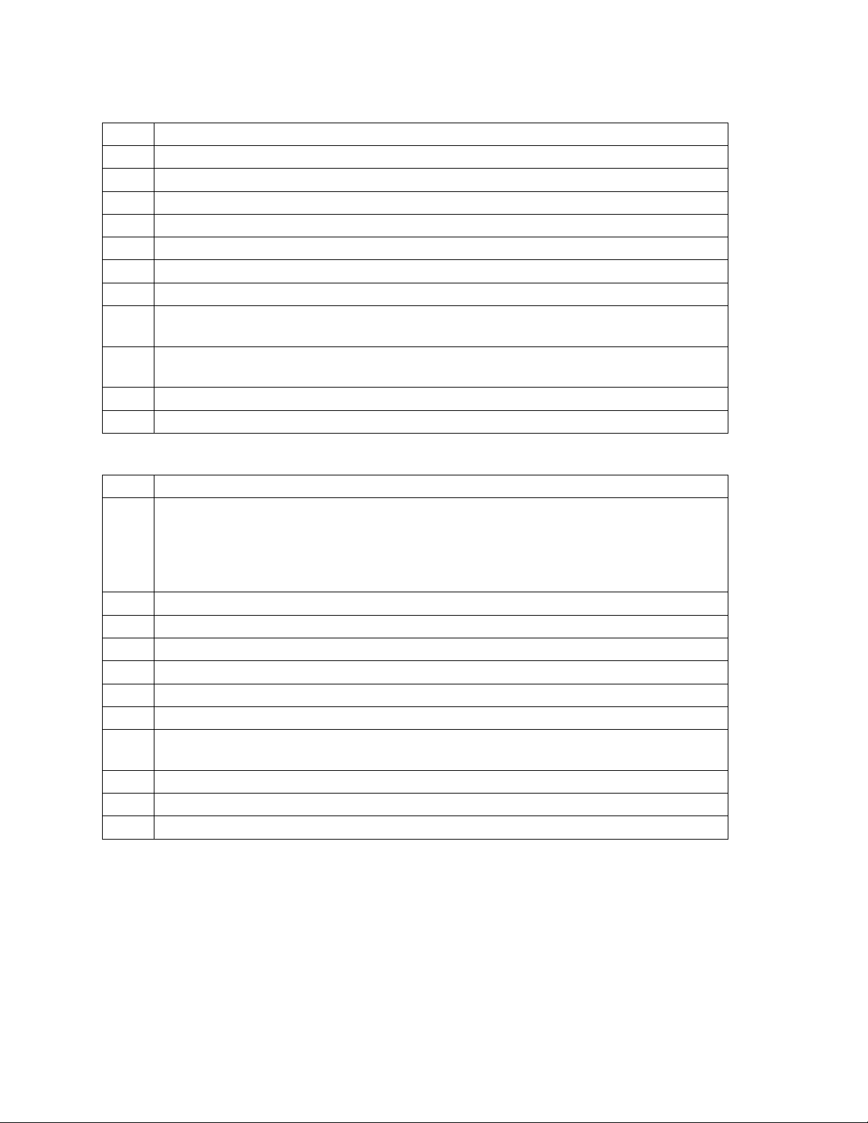
Code 93 (Style 15)
1 Bars per character: 3 dark bars and 3 light bars
2 Character set: All 128 ASCII characters
3 Start/Stop characters: Yes. (Stop character has 4 dark bars and 3 light bars)
4 Center character code: None
5 NULL character: Yes
6 Intercharacter gap: No
7 Characters per symbol: Variable
8 Check digit: Always required. Must be generated by data source. See page 58
9 Delimiters: Horizontal tab. (When no tabs are defined, a space is inserted.),
hp_relative
10 HR character s: Currently selected font, special HR font, special OCR-A/OCR-B
font (120 DPI only)
11 CPI at def ault element widths: 6.85
12 Combined st art- stop character length: 0.333"
Code 128 (Style 16)
1 Bars per character: 3 dark bars and 3 light bars
2 Character set: Any of 3 subsets. The printer automatically shifts among subsets
based on the data that you send. Subset A --All standard alphanumeric
keyboard characters, control characters and special characters Subset B --All
standard alphanumeric keyboard characters, lower case alpha characters and
special characters Subset C --Set of 100 digit pairs from 00 to 99
3 Start/Stop characters: Yes
4 Center character code: None
5 NULL character: Yes
6 Intercharacter gap: None
7 Characters per symbol: Variable
8 Check digit: Automatically generated by the printer. (Cannot be disabled.)
9 Delimiters: Horizontal tab. (When no tabs are defined, a space is inserted.),
hp_relative
10 Autom atic data compression and subset selection
11 CPI at def ault element widths: 11.07
12 Combined st art- stop character length: 0.583"
7265 Programmer’s Manual
Copyright © 2004 TallyGenicom Chapter 3 ANSI Bar Codes
54
Page 59
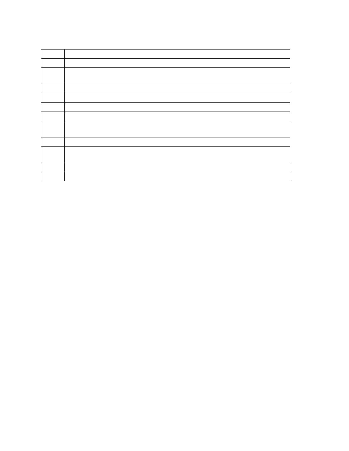
MSI (Style19)
1 Bars per character: 4 dark bars and 4 light bars
2 Character set: 0 through 9
3 Start characters: 1 dark bar and 1 light bar Stop characters: 2 dark bars and 1
light bar
4 Center character code: None
5 NULL character: Yes
6 Intercharacter gap: None
7 Characters per symbol: Variable
8 Check digit: The check digit
can be supplied by the data source
9 Delimiters: Space, comma, horizontal tab, hp_relative
10 HR characters: Currently selected font, special HR font, special OCR-A/OCR-B
font (120 DPI only)
11 CPI at default element widths: 3.8
12 Combined start-stop character length: 0.153"
7265 Programmer’s Manual
Copyright © 2004 TallyGenicom Chapter 3 ANSI Bar Codes
55
Page 60

POSTNET (Style 50)
You cannot adjust POSTNET bar code attributes with ESC[(p1);..(p12)}. All attribute parameters
except the style parameter (p1) are ignored by POSTNET, although they are processed, saved,
and would apply to a subsequent bar code of another style if not overwritten. To select
POSTNET, you need to send only ESC [50}. You cannot print human-readable characters with
this bar code style.
There are three variations of POSTNET. They are ZIP, ZIP+4, and ABC. The printer determines
which variation is being called for by the number of characters in the symbol string. Legal
characters are the numerals 0 - 9 (30 hex - 39 hex) and the dash symbol (2D hex), which is
ignored. Any other printable characters in the symbol string cause an error character (diamond) to
be printed.
ZIP 5 digits plus 1 check digit
ZIP+4 9 digits plus 1 check digit
ABC 11 digits plus 1 check digit
The check digit is the digit that makes the sum of the digits in the symbol string, including the
check digit, evenly divisible by 10. For example, if you send the ZIP symbol string "12345", then
the sum of those five digits is 15, so "123455" would be the complete ZIP symbol.
If you do not send a check digit, then the printer computes it and prints it. If you do send a check
digit, the printer compares your check digit with its internal computation; and if the two numbers
do not agree, then an error character is printed.
7265 Programmer’s Manual 56
Copyright © 2004 TallyGenicom Chapter 3 ANSI Bar Codes
Page 61
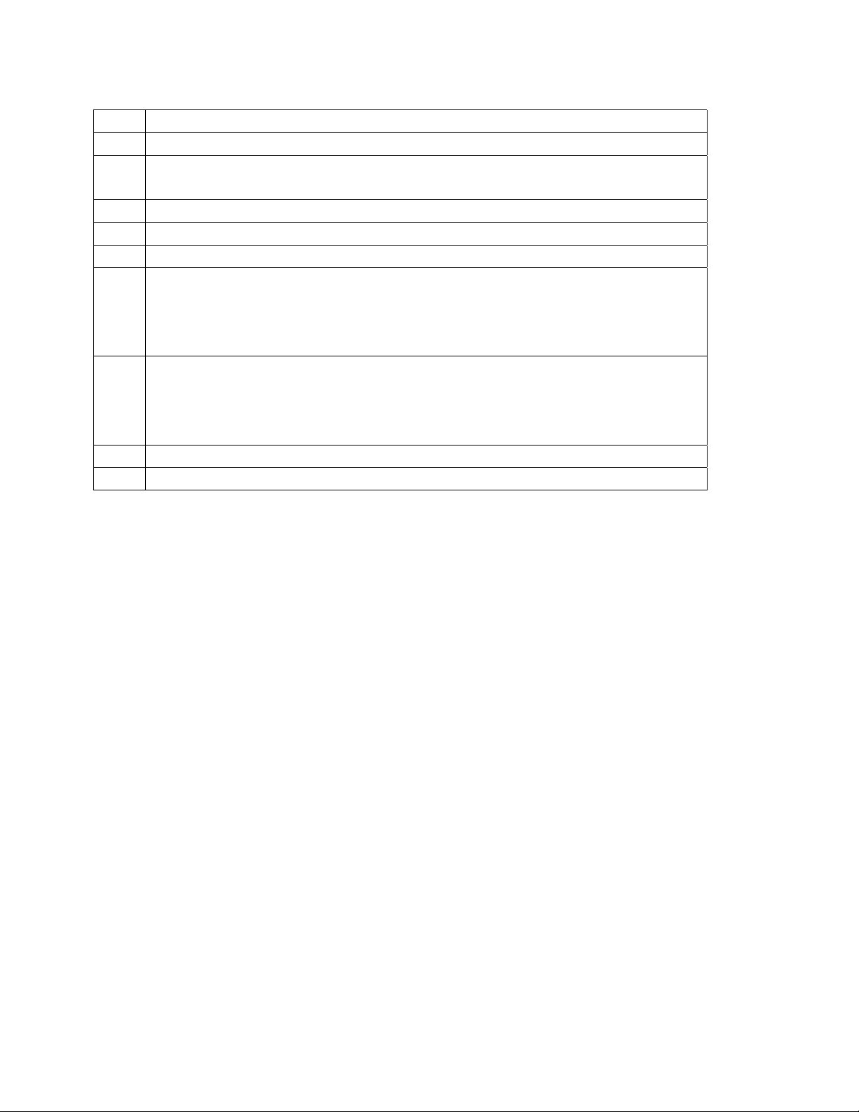
1 Bars per character: 2 tall bars and 3 short bars
2 Character set: 0 through 9
3 Start characters: 1 tall bar
Stop characters: 1 tall bar
4 Center character code: None
5 NULL character: diamond symbol
6 Intercharacter gap: Yes
7 Characters per symbol:
ZIP - 5 + 1 check character
ZIP+4 - 9 + 1 check character
ABC - 11 + 1 check character
8 Check digit: yes.
If a check digit is not sent, then the printer adds it.
If a check digit is sent, then the printer verifies it.
If a user-supplied check digit is wrong, then an error character is printed.
9 Delimiters: Space, comma, horizontal tab
10 HR character s: none
7265 Programmer’s Manual
Copyright © 2004 TallyGenicom Chapter 3 ANSI Bar Codes
57
Page 62
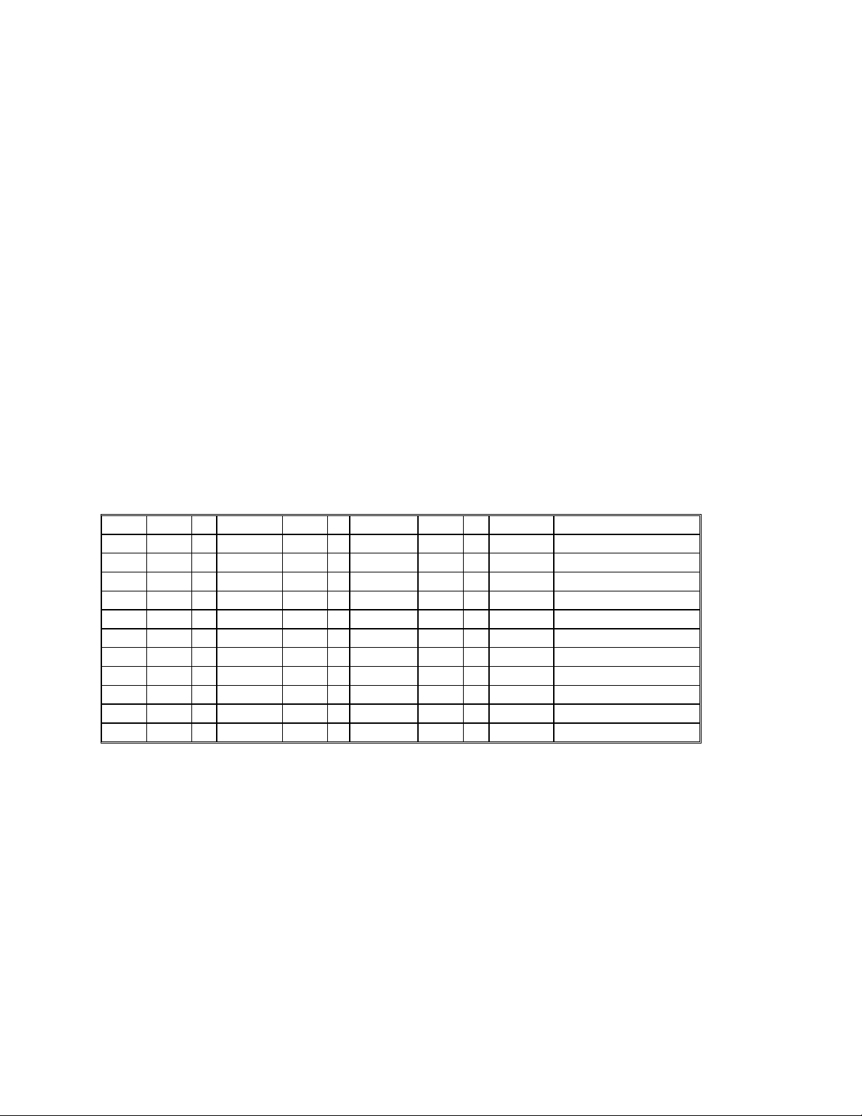
Calculating the Checksum for Code 3 of 9
A 3 of 9 symbol is a variable-length string which can include the digits 0 - 9, uppercase A - Z, and
six additional punctuation characters. The values used to compute the checksum for a 3 of 9
symbol are the locations of individual characters in the unique 3 of 9 character table. Your
program will need to refer to a 3 of 9 look-up table to acquire values for the characters you want
to encode, and again to convert the computed checksum back to a valid 3 of 9 character.
The check digit is the modulus 43 sum of all the character values in a given symbol.
1. Compute the check character for the character string:
12345ABCDE/
2. Sum the values of the characters based on their locations in the 3 of 9 character table:
1 + 2 + 3 + 4 + 5 + 10 + 11 + 12 + 13 + 14 + 40 = 115
3. Compute the modulus 43 of the sum:
115/43 = 2 Remainder 29
4. The check character is the character corresponding to location 29 in the 3 of 9 character
table, which is T. Send to the printer:
12345ABCDE/T
Code 3 of 9 Character Table
0 0 12 C 24 O 36 - (minus sign)
1 1 13 D 25 P 37 . (period)
2 2 14 E 26 Q 38 (space)
3 3 15 F 27 R 39 $
4 4 16 G 28 S 40 /
5 5 17 H 29 T 41 +
6 6 18 I 30 U 42 %
77 19 J 31 V
88 20 K 32 W
99 21 L 33 X
10 A 22 M 34 Y
11 B 23 N 35 Z
Calculating the Checksum for CODE 93
A Code 93 symbol consists of a start code, a variable number of data characters, two check digits
(referred to as "C" and "K"), and a stop code.
The values used to compute the checksum for a Code 93 symbol are the locations of individual
characters in the Code 93 character table. Check digit "C" is the modulo 47 sum of the character
values and a weighting sequence, where the weights from right to left are in the sequence 1, 2,
3...19, 20, 1, 2, 3...19, 20....
Check digit "K" is the modulo 47 sum of the character values and a weighting sequence, where
the weights from right to left, starting with the check character "C", are in the sequence
1, 2, 3...14, 15, 1, 2, 3...14,15....
7265 Programmer’s Manual
Copyright © 2004 TallyGenicom Chapter 3 ANSI Bar Codes
58
Page 63
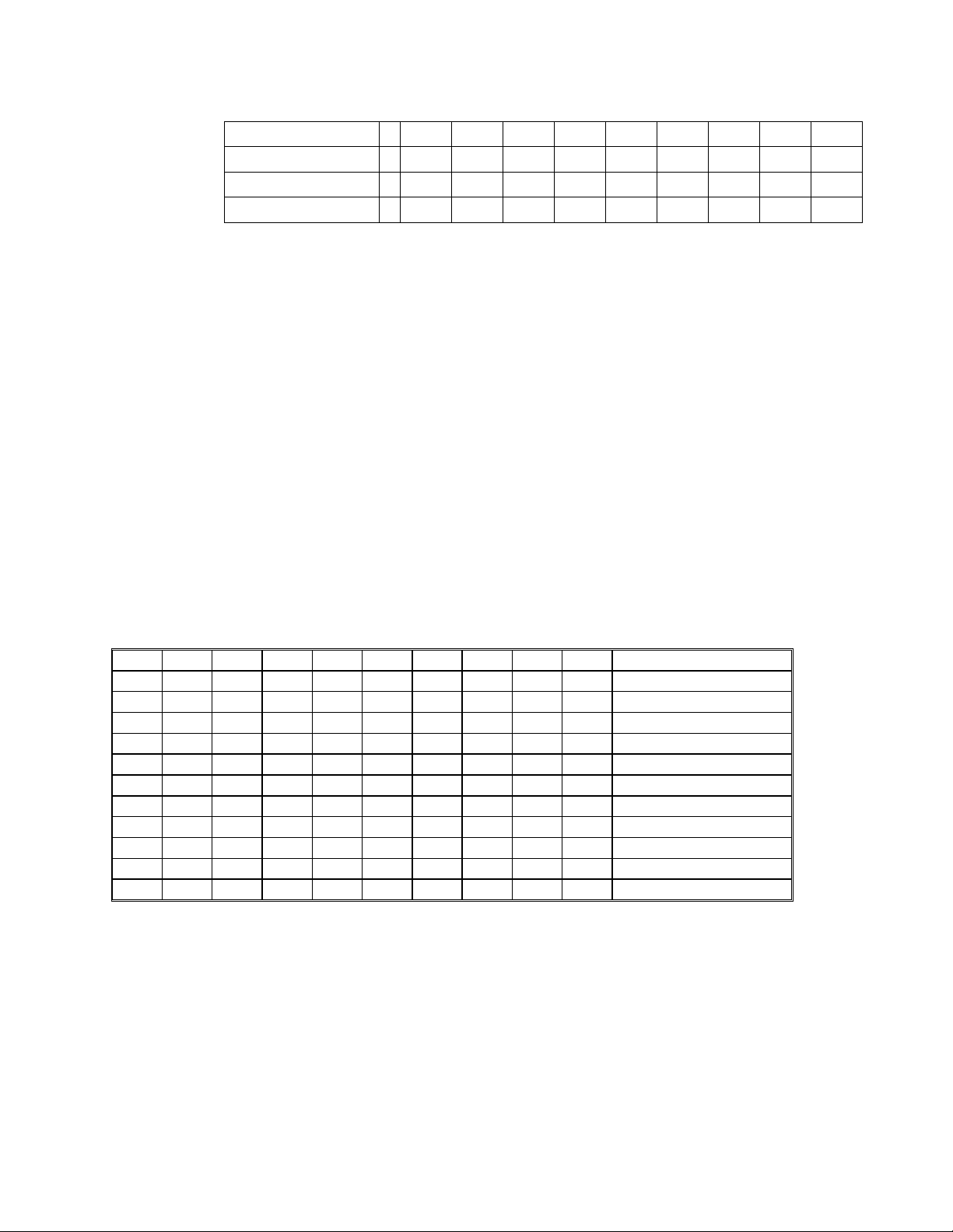
The following example illustrates the calculation of the check digits for the symbol CODE 93.
Data CODEsp93"C""K"
Data Values 12 24 13 14 38 9 3
C Weights 7654321
K Weights 87654321
1) For "C", sum the products of the (C WEIGHTS * DATA VALUES).
(1 * 3) + (2 * 9) + (3 * 38) + (4 * 14) + (5 * 13) + (6 * 24) + (7 * 12) = 484
2) Divide 484 by 47.
484 / 47 = 10 remainder 14.
3) Therefore, the value of "C" is 14, which corresponds to character E.
4) For "K", sum the products of the (K WEIGHTS * DATA VALUES), starting with the newly
calculated "C" digit.
(1*14) + (2*3) + (3*9) + (4*38) + (5*14) + (6*13) + (7*24) + (8*12) = 611
5) Divide 611 by 47.
611 / 47 = 13 remainder 0
6) The value of "K" therefore is 0, corresponding to character 0. Send to the printer:
CODE 93E0
The Code 93 character table is the same as the Code 3 of 9 character table, except that there are
four additional “control characters” at the end.
Code 93 Character Table
0 0 12 C 24 O 36 - (minus sign)
1 1 13 D 25 P 37 . (period)
2 2 14 E 26 Q 38 (space)
3 3 15 F 27 R 39 $
4 4 16 G 28 S 40 /
5 5 17 H 29 T 41 +
6 6 18 I 30 U 42 %
7 7 19 J 31 V 43 <CTRL> $
8 8 20 K 32 W 44 <CTRL> %
9 9 21 L 33 X 45 <CTRL> /
10 A 22 M 34 Y 46 <CTRL> +
11 B 23 N 35 Z
7265 Programmer’s Manual
Copyright © 2004 TallyGenicom Chapter 3 ANSI Bar Codes
59
Page 64

Code 93 Checksums for Full ASCII
You can send any of the 128 ASCII characters verbatim in a Code 93 symbol. You would not
need to worry about Code 93 control codes if you did not need to compute checksums.
The four control characters in the Code 93 character table do not correspond to any byte values
sent to the printer, but instead refer to “precedence codes” that the printer generates. If you send
the printer a lowercase “a” in a Code 93 symbol, for instance, then the printer prints bars and
spaces that correspond to the <CTRL> + code in front of bars and spaces that correspond to the
uppercase “A”. The reader then interprets this character combination as a lowercase “a”.
So far, this process is transparent both to routines sending symbol strings to the printer and to
routines receiving decoded data from the reader. When ASCII characters are represented as
character combinations, however, the reader expects to see a checksum based on the values of
these combinations; this is the reason that the control codes are assigned values in the Code 93character table. The following example illustrates the calculation of the check digits for the
symbol Cat :
7265 Programmer’s Manual
Copyright © 2004 TallyGenicom Chapter 3 ANSI Bar Codes
60
Page 65

Checksum calculation for the symbol Cat
Data C <CTRL> + A <CTRL> + T "C" "K"
Data Values 12 46 10 46 29
C Weights5432 1
K Weights654 3 21
1) For "C", sum the products of the (C WEIGHTS * DATA VALUES).
(1 * 29) + (2 * 46) + (3 * 10) + (4 * 46) + (5 * 12) = 395
2) Divide 395 by 47.
395 / 47 = 8 remainder 19.
Therefore, the value of "C" is 19, which corresponds to character J.
3) For "K", sum the products of the (K WEIGHTS * DATA VALUES), starting with the newly
calculated "C" digit.
(1*19) + (2*29) + (3*46) + (4*10) + (5*46) + (6* 12) = 557
4) Divide 557 by 47.
611 / 47 = 11 remainder 40
5) The value of “K” therefore is 40, corresponding to character /. Send to the printer:
7265 Programmer’s Manual
Copyright © 2004 TallyGenicom Chapter 3 ANSI Bar Codes
61
Page 66

Code 93 Full ASCII Table
Code Code Code Code
ASCII
93 ASCII 93 ASCII 93 ASCII 93
NUL
SOH
STX
ETX
EOT
ENQ
ACK
BEL
BS
HT
LF
VT
FF
CR
SO
SI
DLE
DC1
DC2
DC3
DC4
NAK
SYN
ETB
CAN
EM
SUB
ESC
FS
GS
RS
US
%U SP space @ %V ` %W
$A ! /A A A a +A
$B " /B B B b +B
$C # /C C C c +C
$D $ $ D D d +D
$E % % E E e +E
$F & /F F F f +F
$G ' /G G G g +G
$H ( /H H H h +H
$I ) /I I I i +I
$J * /J J J j +J
$K + + K K k +K
$L , /L L L l +L
$M - - M M m +M
$N . . N N n +N
$O / / O O o +O
$P 0 0 P P p +P
$Q 1 1 Q Q q +Q
$R 2 2 R R r +R
$S 3 3 S S s +S
$T 4 4 T T t +T
$U 5 5 U U u +U
$V 6 6 V V v +V
$W 7 7 W W w +W
$X 8 8 X X x +X
$Y 9 9 Y Y y +Y
$Z : /Z Z Z z +Z
%A ; %F [ %K { %P
%B < %G \ %L | %Q
%C = %H ] %M } %R
%D > %I ^ %N ~ %S
%E ? %J _ %O DEL %T
7265 Programmer’s Manual
Copyright © 2004 TallyGenicom Chapter 3 ANSI Bar Codes
62
Page 67

Chapter 4.
ANSI Oversized Font
This chapter describes the characteristics and lists the ANSI control sequences for the rotatable
oversized font, a unique sans-serif font with character shapes designed to accommodate very
large expansions. This is an industrial-strength feature. Horizontal resolution is held to 120 dpi to
enable oversized printing at carriage speeds of up to 50 inches per second. Combined with
vertical logic seeking, this enables the 7265 to print complex mixes of character sizes and
rotations at creditable throughputs.
The oversized font is monospaced only. ANSI print modes: bold, underscored, doublewide, and
proportional have no effect. You can print characters 20 hex through 7F hex; characters above
this range are ignored. User-defined character substitutions do not work in oversized, so you
cannot use the IBM line-draw characters. The resident international character substitutions work
the same as in normal text.
In contrast to the oversized function on earlier products, the 7265 interprets escape sequences
and control codes within an oversized string. As of this writing, however, we recommend that you
exit oversized before sending any other control functions.
To maintain compatibility with existing printers, the 7265 printer does not back paper up to print
oversized characters on the current baseline. If you enter an oversized mode and immediately
print one character, then the top of the character is at the vertical position that was current when
you entered oversized. This is no problem if all characters on a line are the same size. To mix
oversized with either normal type or with different expansions on the same baseline, however,
you will need to write a routine to find the baseline. We cover this later in this chapter.
Some of the oversized control sequences are redundant. The nonrotatable controls that let you
optionally toggle oversized with SHIFT OUT and SHIFT IN are retained for compatibility with older
printers. You could reasonably choose to use only the escape sequences for rotatable oversized
(ESC [(Ps)| ) for new applications.
7265 Programmer’s Manual
Copyright © 2004 TallyGenicom Chapter 4 ANSI Oversized
63
Page 68

Control Function Summary
Control Function Description
SO Activate Oversized, Expanded, Barcode
SI Exit Oversized, Expanded, Barcode
ESC [0t Cancel Oversized, Expanded, Barcode
ESC [1t Non-rotatable Oversized
ESC [2t Expanded Printing
ESC [Pv;Ph<sp>B Set Character Size
ESC[0| Exit Oversized
ESC[p1| Set Oversized
Oversized Control Functions
Commands Description
SO ACTIVATE OVERSIZED / EXPANDED / BAR CODE
Dec 14 Hex 0E
SI EXIT OVERSIZED / EXPANDED / BAR CODE
Dec 15 Hex 0F
ESC [0t CANCEL OVERSIZED / EXPANDED / BAR CODE
Cancels oversized, whether set with ESC [1t or ESC [(Ps)|, and also expanded and
bar code modes. This command does not clear the oversized dimensions set by ESC
[(Pv);(Ph)<sp>B.
Dec 27 91 48 116 Hex 1B 5B 30 74
ESC [1t NON-ROTATABLE OVERSIZED
Included for compatibility with older products. Use if you want to toggle oversized with
SHIFT OUT and SHIFT IN.
Dec 27 91 49 116 Hex 1B 5B 31 74
ESC [2t EXPANDED PRINTING
Selects expanded (as opposed to the oversized) printing at the current
expansion factor. Dec 27 91 50 116 Hex 1B 5B 32 74
7265 Programmer’s Manual 64
Copyright © 2004 TallyGenicom Chapter 4 ANSI Oversized
Page 69

Commands Description
ESC
[Pv;Ph<sp>B
SET CHARACTER SIZE
Sets the expansion of oversized characters in percentage points. Pv is the vertical
expansion and Ph is the horizontal expansion. The parent font is a 10-point font.
Dimensions established by this sequence are stored in nonvolatile RAM while power is
off.
Caution: Any text between receipt of this command and a countermanding mode
selection command, either ESC [(Ps)| or ESC[(Ps)t, will be printed in expanded mode.
If you do not want this to happen, then you must follow this command immediately with
a mode selection command.
The range of valid parameters (in the sense that a valid parameter does not abort the
escape sequence) is 0 <= Pn < 32767. The printer rounds off dimension parameters
as follows:
If Pn < 100, then Pn = 100
If 100 < Pn < 18700, then Pn is rounded down to the nearest 100.
If Pn >= 18700, then Pn = 18700
Example - to set 20-point type at 1:1 aspect ratio:
Dec 27 91 50 48 48 59 50 48 48 32 66
Hex 1B 5B 32 30 30 3B 32 30 30 20 42
ESC
[0|
ESC
[p1|
EXIT OVERSIZED
Dec 27 91 48 125
Hex 1B 5B 31 7C
SET OVERSIZED
p1 = 1-4
Dec 27 91 49-52 124
Hex 1B 5B 31-34 7C
7265 Programmer’s Manual
Copyright © 2004 TallyGenicom Chapter 4 ANSI Oversized
65
Page 70

Oversized Versus Expanded
There are two ANSI functions that print characters scaled according to the Graphics Size Modification
parameters. Both expanded and oversized are standard features with this printer. You can get into expanded
mode accidentally when you send the Graphic Size Modification sequence.
100 LPRINT CHR$(27);"[720e"; 'vp_relative
110 LPRINT "Expanded ";
120 LPRINT CHR$(27);"[400;400 B"; 'graphic size mod
130 LPRINT "ABCj" 'drops into expanded
140 LPRINT CHR$(27);"[0t"; 'cancel mode
150 LPRINT "Oversized ";
160 LPRINT CHR$(27);"[1|"; 'set oversized
170 LPRINT "ABCj"
180 LPRINT CHR$(27);"[0t" 'cancel mode
Figure 4-1 Expanded and Oversized
Expanded mode is based on the current font, is limited to 8x the parent font size, and propagates
up from the baseline. Reverse paper motion occurs for vertical expansions. The horizontal
resolution reflects the current font selection. If you send a line feed character while in expanded
mode, then the paper advances by the current vertical expansion factor times the current linefeed increment.
Oversized is based on a unique font, is rotatable, expandable to 1870x, and propagates down
from the top of the character cell. The resolution is always 120 dpih x 144 dpiv. If you send a line
feed character while in oversized, then paper advances five dot rows for 0
nine dot rows for 270
obviously better.
o
rotation. The scaling algorithms for the oversized function are
o
rotation, or
Setting the Expansion
The size of the parent oversized font is 10 points (12 cpi). You can set the horizontal and vertical
dimensions of oversized characters separately in increments of 100% of the parent font size.
Limits are 100% to 18,700%. The larger number corresponds to an uppercase M about 18.7
inches high. The control sequence that sets the expansion is the ANSI Graphic Size Modification:
7265 Programmer’s Manual
Copyright © 2004 TallyGenicom Chapter 4 ANSI Oversized
66
Page 71

ESC [(pv);(ph)<SP>B
where (pv) is the vertical expansion, (ph) is the horizontal expansion, and <SP> is the space
character (20 hex).
o
For 0
rotation, you can think of parameter (pv) as 10 times the point size of the
oversized character. If you set a 600 x 600 expansion and print an uppercase “E” at zero rotation,
then the resulting character will nearly match the 60-point Helvetica “E” on a typesetter's scale.
A sideways character shares neither the size nor the aspect ratio of a vertical character printed at
the same expansion factors. Relationships between expansion and character dimensions for
o
rotation reflect differences in the horizontal and vertical resolutions of the printer in
270
oversized mode.
Remember to always follow the graphic size modification command immediately with either ESC
[0t or the desired oversized mode selection if you do not want to drop into expanded mode.
Device Timeout with Very Large Characters
Normally, one byte of data in the printer's input buffer represents one text character, which takes
milliseconds to print. If our host creates a huge character using dot graphics, then one byte of
data in the buffer corresponds to one dot column. If we set oversized, however, then one byte of
data can command the printer to render several hundred thousand dot columns. A big oversized
character can take a while to print.
If we fill the printer's input data buffer while a big oversized character is printing, then the printer
goes BUSY. The big character, as well as a buffer full of following objects, has to be printed
before the printer goes READY again.
If the host now tries for some period of time to send data to the printer without seeing a READY at
the interface, then the host might decide that the printer is not working, show you a device
timeout message, and abort the data transfer.
This same possibility exists with large bar codes, and we discuss remedies in the ANSI Bar Code
chapter.
7265 Programmer’s Manual
67
Copyright © 2004 TallyGenicom Chapter 4 ANSI Oversized
Page 72

What is a Character Cell?
A character cell is the rectangular array of locations at which dots can be printed to form one
character.
All character cells for a given monospaced font at a given pitch are the same size. If you print a
line of characters with no countermanding motion instructions, then no character cell will impinge
horizontally on the character cell of an adjacent character. You can determine character cell width
in a monospaced font by measuring the distance from the leading edge of, say, an uppercase “E”
to the leading edge of an adjacent uppercase “E”.
In an impact-matrix printer font, the printed portion of a character is often centered horizontally in
the character cell. There might be a fixed number of dot columns on either end of the character
cell that are never printed. This is analogous to the side bearings in a typeset character.
Figure 4-2 Character Cells
In the oversized font, on the other hand, characters are left-justified in the cells. This lets you print
a larger character when you are printing, say, one huge character on a sheet. The 7265 printer
prints as much of an oversized character as will fit between the margins. If your character is going
to be clipped at the right margin, then you might rather clip the side bearing than clip a printed
portion of that character.
In the oversized font, the topmost dot in the uppercase “E”, for instance, is centered on the upper
boundary of the character cell. The lowest dot on the descender of the lowercase “j” is centered
on the lower boundary of the character cell.
7265 Programmer’s Manual
Copyright © 2004 TallyGenicom Chapter 4 ANSI Oversized
68
Page 73

Oversized Character Dimensions – 0
The width of an oversized character cell is 0.72 decipoints times the
horizontal expansion factor. In thousandths of an inch, it is the same as the horizontal expansion
factor. If you set a horizontal expansion of 1000, then characters will be 1 inch, or 720 decipoints,
apart.
Figure 4-3 Vertical Characte r Dimensions
o
The height of an oversized character cell is 0.9 decipoints times the
vertical expansion factor. In thousandths of an inch, it is 1.25 times the vertical expansion factor.
If you set a vertical expansion of 1000, then the top of the uppercase “E” is 1.25 inches, or 900
decpoints, from the bottom of the lowercase “j”.
The distance from the top of an oversized character cell to the baseline
is 0.7 decipoints times the vertical expansion factor. Top of the character cell means the upper
boundary of the cell before it was rotated.
7265 Programmer’s Manual
Copyright © 2004 TallyGenicom Chapter 4 ANSI Oversized
69
Page 74

Oversized Character Dimensions - 270
The width of a character cell is 0.6 decipoints times the horizontal
expansion factor. Width means the dimension that is left-to-right as you read the character.
The height of a character cell is 1.08 decipoints times the vertical
expansion factor. Height means the dimension that is vertical as you read the character.
Figure 4-4 Sideways Character Dimensions
The distance from the top of the character cell to the baseline is 0.76
decipoints times the vertical expansion factor. Top-of-cell means the upper boundary of the
character cell as you read the character.
o
When printing strings of sideways characters, the printer adds horizontal space between
character cells. This space is equal to 0.36 decipoints times the vertical expansion factor.
Vertical Position-Relative in Oversized
Normally, the origin of a vertical position-relative move is the current position. If the last object
printed on the current line was an oversized character, however, then the origin of a vertical
position-relative move is the top of that character cell, where top-of-cell means the character cell
boundary that is uppermost on the paper. This is true whether or not you are still in oversized
when the vertical position-relative command is sent.
7265 Programmer’s Manual
Copyright © 2004 TallyGenicom Chapter 4 ANSI Oversized
70
Page 75

Implementing the Line Feed Function - 0
A good technique is to exit oversized with ESC [0t and send a vertical and horizontal position
absolute command:
ESC [(Pv);(Ph)f
where (Pv) is decipoints from the top print reference and (Ph) is decipoints from the left print
reference. The logic seeking of the printer minimizes redundant paper motion associated with
position-absolute commands. You could also use vertical position-relative to implement line
feeds.
Try a line feed increment of 1.2 decipoints times the vertical expansion
factor.
If you send a line feed character while in oversized, then paper advances five dot rows for the 0
rotation.
o
o
7265 Programmer’s Manual
Copyright © 2004 TallyGenicom Chapter 4 ANSI Oversized
71
Page 76

Line Spacing and Intercharacter Spacing - 270
If you print sideways text, then the vertical move that otherwise corresponded to a line feed now
sets the distance from the leading edge of one character cell to the leading edge of the next
character cell (as you read the characters). A good starting value for this move is the character
cell width, which is 0.6 decipoints times the horizontal expansion factor.
Strings of sideways characters propagate left-to-right across the portrait page. The printer makes
“ line feeds” for you by inserting space between the trailing cell boundary of the previous
character and the leading cell boundary of the next character. This space is 0.36 decipoints times
the vertical expansion factor, which is generous line spacing.
If this line spacing is not satisfactory, then send sideways text one character at a time, preceded
by a locating command for each character. If you use the resident line spacing for sideways lines,
then you will probably use a character array to rotate text. In that case, remember to fill your array
with space characters (20 hex) before you copy strings into it.
o
7265 Programmer’s Manual
Copyright © 2004 TallyGenicom Chapter 4 ANSI Oversized
72
Page 77

Appendix A. Commands and Exceptions
Supported Control Codes and Escape Sequences
ACK Acknowledge
BEL Bell
BS Back Space
CR Carriage Return
CSI Control String Introducer, ESC [
DC1 Select printer (Data Control 1)
DC3 Deselect printer (Data Control 3)
DEL Delete
ENQ Enquiry
ESC Escape
ESC \ or ST String Terminator
ESC c Reset to Initial State (RIS)
ESC D or IND Index
ESC E or NEL Next line
ESC H or HTS Horizontal Tab Setting
ESC J or VTS Vertical Tab Setting
ESC K or PLD Partial Line Down
ESC L or PLU Partial Line Up
ESC M or RI Reverse Index
ESC P data or DCS Enter Dot Graphics Mode (Device Control String)
ESC [ p1; pn } Sets bar code parameters (GENBC)
ESC [ p1;....pn m Select Graphics Rendition (SGR), Character Pitch, Print Modes and
Color Ribbon color.
ESC [ p1; p2 SP B Graphic Size Modification (GSM)
ESC [ p1; p2 s Left/Right Margin Set (GENSLR)
ESC[ p1; pn u Sets horizontal tab stops at specified positions
Multiple Horizontal Tab Set (GENHTS)
ESC [ p1; pn g Tab Clear (TBC)
ESC [ p1; pn v Sets vertical tab stops at specified positions
(Multiple Vertical Tab Set - GENVTS)
ESC [ p1; p2; p3 r Form Definition (GENFD)
ESC [ p1; p2 <SP> G Sets the line/character spacing
ESC [ p1;...pn h Set Mode (SM)
ESC [ p1; pn l Reset mode (RM)
ESC [ p1 ’ Horizontal Position Absolute (HPA)
ESC [ p1 a Horizontal Position Relative (HPR)
ESC [ p1 d Vertical Position Absolute (VPA)
ESC [ p1 j Horizontal Position Backward (HPB)
ESC [ p1 k Vertical Position Backward (VPB)
ESC [ p1 q Select Graphics Mode/Density(GENGRM)
ESC [ p1 t Special Print Mode (Oversize/Expanded/Bar code Mode - GENSPM)
ESC [ p1; p2 f Horizontal and Vertical Position Absolute (HVP)
ESC [ p1 e Vertical Position Relative (VPR)
ETX End of transmission
FF Form Feed
HT Horizontal tab
LF Line Feed
NUL Ignored
OSC Operating System Command, ESC ]
SI Shift In
SO Shift Out
SP Space
VT Vertical tab
Page 78

Commands not implemented in the 7265 ANSI Emulation
ESC ] p1;pn<ST> User Defined Character Substitution (GENUDS)
ESC ] p1;p2;p3;data<ST> Operating system command (Load Mode OSC)
ESC [ p1;p2 SP ~ Selects emulation (GENEMU)
ESC [ p1;pn { Unidirectional Printing (GENUPD)
ESC [ p1;p2;p3 SP | Customer Setup Save/Unsave (GENCSX)
ESC [ p1;pn p Assign Source for Forms (GENASF)
ESC [ p1 x Selects National character set (Select National Characters - GENSNC)
ESC k Print Test Character (GENPTC)
ESC Q or PU1 Executes Self Test
Exceptions
1.) Barcode ratios are controlled by one parameter that affects both width and height.
2.) Block characters print at a fixed size.
3.) Block characters printed with a fixed rotation.
4.) The Genicom printer saves ESC sequence changes to powerup; we load from the powerup menu.
5.) <DEL> character prints a space; Genicom prints a “house” character.
6.) Across 13.6 inches we print one less character per line in the following CPI's:
6, 6.25, 6.67, 8.33, 8.57, 9, 12, 12.5, 13.3, 17.14 and 18
7.) If we set Auto CR to ON then form feeds also get a CR, where Genicom does not add CR to form feeds.
Genicom does add CR to FF if "Auto CR on Vertical Tab" is enabled.
8.) Different combinations of adding and removing vertical tabs will produce different results compared to the
Genicom printer.
9.) Differences when mixing some form lengths with top and bottom margins.
10.) Some illegal parameters are treated different than the Genicom printer.
11.) Default horizontal and vertical tabs are not defined at power up.
Page 79

Programmer's Reference
EPSON Emulation
Page 80

Table of Contents
Description of Escape Sequences
Introduction
Paper and Text Formatting
Form Length . . . . . . . . . . . . . . . . . . . . . . . . . . . . . . 5
Page Length in Units . . . . . . . . . . . . . . . . . . . . . . . . . 7
Page Format . . . . . . . . . . . . . . . . . . . . . . . . . . . . . . 7
Perforation Skip . . . . . . . . . . . . . . . . . . . . . . . . . . . . 10
Right Margin . . . . . . . . . . . . . . . . . . . . . . . . . . . . . . 12
Left Margin . . . . . . . . . . . . . . . . . . . . . . . . . . . . . . . 12
Justification and Centering . . . . . . . . . . . . . . . . . . . . . . 14
Character Spacing
HMI (Horizontal Motion Index) . . . . . . . . . . . . . . . . . . . . . 16
Enlarged print mode . . . . . . . . . . . . . . . . . . . . . . . . . . 18
Continuous enlarged print mode . . . . . . . . . . . . . . . . . . . 18
Condensed Character Density . . . . . . . . . . . . . . . . . . . . 20
Character Density 10 cpi . . . . . . . . . . . . . . . . . . . . . . . 21
Character Density 12 cpi . . . . . . . . . . . . . . . . . . . . . . . 21
Character Density 15 cpi . . . . . . . . . . . . . . . . . . . . . . . 21
Proportional Spacing . . . . . . . . . . . . . . . . . . . . . . . . . 23
Character Spacing . . . . . . . . . . . . . . . . . . . . . . . . . . . 24
Line Spacing
Fixed Line Spacing 1/8 inch . . . . . . . . . . . . . . . . . . . . . . 25
Fixed Line Spacing 7/72 inch . . . . . . . . . . . . . . . . . . . . . 25
Fixed Line Spacing 1/6 inch . . . . . . . . . . . . . . . . . . . . . . 25
Variable Line Spacing n/180 or n/216 Inch . . . . . . . . . . . . . . 27
Variable Line Spacing n/60 or n/72 Inch . . . . . . . . . . . . . . . . 27
Variable Line Spacing n/360 Inch . . . . . . . . . . . . . . . . . . . 27
. . . . . . . . . . . . . . . . . . . . . . . . . . . . . . . . . 2
. . . . . . . . . . . . . . . . . . . . . . . . . 5
. . . . . . . . . . . . . . . . . . . . . . . . . . . . . 16
. . . . . . . . . . . . . . . . . . . . . . . . . . . . . . . . 25
Page 81

Character Styling . . . . . . . . . . . . . . . . . . . . . . . . . . . . . . 29
Super-/Subscript Mode ON . . . . . . . . . . . . . . . . . . . . . . 29
Double Strike . . . . . . . . . . . . . . . . . . . . . . . . . . . . . 31
Select Font and Pitch by Point . . . . . . . . . . . . . . . . . . . . 32
Print Quality . . . . . . . . . . . . . . . . . . . . . . . . . . . . . . 34
Font Type Selection . . . . . . . . . . . . . . . . . . . . . . . . . . 35
Typeface Selection . . . . . . . . . . . . . . . . . . . . . . . . . . 37
Emphasized Mode . . . . . . . . . . . . . . . . . . . . . . . . . . . 38
Underline Mode . . . . . . . . . . . . . . . . . . . . . . . . . . . . 39
Score Selection . . . . . . . . . . . . . . . . . . . . . . . . . . . . 40
Italic Mode . . . . . . . . . . . . . . . . . . . . . . . . . . . . . . . 42
Print Mode Selection . . . . . . . . . . . . . . . . . . . . . . . . . 43
Double Height . . . . . . . . . . . . . . . . . . . . . . . . . . . . . 46
Print Positioning . . . . . . . . . . . . . . . . . . . . . . . . . . . . . . 47
Horizontal Tab Stops . . . . . . . . . . . . . . . . . . . . . . . . . 47
Set Horizontal and Vertical Pitch . . . . . . . . . . . . . . . . . . . 49
Horizontal and Vertical Step Forward . . . . . . . . . . . . . . . . . 50
Absolute Horizontal Step . . . . . . . . . . . . . . . . . . . . . . . 51
Relative Horizontal Step . . . . . . . . . . . . . . . . . . . . . . . . 53
Vertical Tab Stops . . . . . . . . . . . . . . . . . . . . . . . . . . . 55
Set/Reset Vertical Tabs in Channels . . . . . . . . . . . . . . . . . 57
Select Vertical Tab Channel . . . . . . . . . . . . . . . . . . . . . . 57
Set Absolute Vertical Print Position . . . . . . . . . . . . . . . . . . 59
Set Relative Vertical Print Position . . . . . . . . . . . . . . . . . . 59
Set Unit . . . . . . . . . . . . . . . . . . . . . . . . . . . . . . . . 62
Graphics . . . . . . . . . . . . . . . . . . . . . . . . . . . . . . . . . . . 63
Select Graphics Mode . . . . . . . . . . . . . . . . . . . . . . . . . 67
Graphics 60 dpi . . . . . . . . . . . . . . . . . . . . . . . . . . . . 63
Graphics 120 dpi . . . . . . . . . . . . . . . . . . . . . . . . . . . 63
Graphics 240 dpi . . . . . . . . . . . . . . . . . . . . . . . . . . . 63
Graphic Modes . . . . . . . . . . . . . . . . . . . . . . . . . . . . 63
Graphics Mode Reassignment . . . . . . . . . . . . . . . . . . . . 69
Graphics Printing with 9 Print Dots . . . . . . . . . . . . . . . . . . 71
Page 82

Download Character Generator . . . . . . . . . . . . . . . . . . . . . . 73
General . . . . . . . . . . . . . . . . . . . . . . . . . . . . . . . . 73
Copy ROM into RAM . . . . . . . . . . . . . . . . . . . . . . . . . 75
Print Raster Graphics . . . . . . . . . . . . . . . . . . . . . . . . . 76
Activate User Defined Character Set . . . . . . . . . . . . . . . . . 79
Download Characters . . . . . . . . . . . . . . . . . . . . . . . . . 80
Draft Character Definition (9 Needle Printer) . . . . . . . . . . . . . 80
Definition of a Character (9 Needle Printer) . . . . . . . . . . . . 81
Attribute"A" (9 Needle Printer) . . . . . . . . . . . . . . . . . . . 83
Descenders (9 Needle Printer) . . . . . . . . . . . . . . . . . . . 83
Proportional Spacing Data (9 Needle Printer) . . . . . . . . . . . 84
Calculation of the Attribute (9 Needle Printer) . . . . . . . . . . . 84
Definition of NLQ Characters (9 Needle Printer) . . . . . . . . . . . 88
24 Needle Printer . . . . . . . . . . . . . . . . . . . . . . . . . . . 92
Miscellaneous . . . . . . . . . . . . . . . . . . . . . . . . . . . . . . . . 95
Print Data as Characters . . . . . . . . . . . . . . . . . . . . . . . 95
Printing Direction unidirectional for one line . . . . . . . . . . . . . . 96
Half-Speed Printing . . . . . . . . . . . . . . . . . . . . . . . . . . 97
Single n/180 inch or n/216 inch line feed . . . . . . . . . . . . . . . 98
Single n/216 inch back feed . . . . . . . . . . . . . . . . . . . . . . 98
Colour Selection . . . . . . . . . . . . . . . . . . . . . . . . . . . . 99
International Character Sets . . . . . . . . . . . . . . . . . . . . . . 101
Character Sets . . . . . . . . . . . . . . . . . . . . . . . . . . . . . 103
Assign Character Table . . . . . . . . . . . . . . . . . . . . . . . . 105
Input Data Control . . . . . . . . . . . . . . . . . . . . . . . . . . . 107
Sheet Feeder . . . . . . . . . . . . . . . . . . . . . . . . . . . . . 108
Print Code Area Expansion . . . . . . . . . . . . . . . . . . . . . . 110
Activate/Deactivate Graphics Characters . . . . . . . . . . . . . . . 112
Activate/Deactivate Direct Print Mode . . . . . . . . . . . . . . . . . 112
International Code Table . . . . . . . . . . . . . . . . . . . . . . . 113
Printer Initialization . . . . . . . . . . . . . . . . . . . . . . . . . . 114
Activate Paper End Sensor . . . . . . . . . . . . . . . . . . . . . . 115
Control Codes . . . . . . . . . . . . . . . . . . . . . . . . . . . . . . . . 116
Page 83

Appendix A Summary of Possible Codes
Sorted by Sequences
Sorted by Functions
. . . . . . . . . . . . . . . . . . . . . . . . . . . . A-2
. . . . . . . . . . . . . . . . . . . . . . . . . . . . A-7
Appendix B Character Sets
Standard Character Set
International Substitution Table - normal font
International Substitution Table - italic font
Graphics Character Set
Standard Character Set, extended
Graphics Character Set, extended
International Character Set
International Character Set, extended
Table of Character Width for Proportional Printing
. . . . . . . . . . . . . . . . . . . . . . . . . . . B-3
. . . . . . . . . . . . . . . . . . . . . . . . . . . B-6
. . . . . . . . . . . . . . . . . . . . . B-7
. . . . . . . . . . . . . . . . . . . . . B-8
. . . . . . . . . . . . . . . . . . . . . . . . . B-9
. . . . . . . . . . . . . . B-4
. . . . . . . . . . . . . . . . B-5
. . . . . . . . . . . . . . . . . . . B-10
. . . . . . . . . . . . B-11
Index
Page 84

Description of Sequences
Introduction
Paper and Text Formatting
Character Spacing
Line Spacing
Character Styling
Print Positioning
Graphics
Download Character Generator
Miscellaneous
Control Codes
Page 85

Introduction
This User’s Manual describes the sum of all EPSON Escape sequences, regardless of
the specific EPSON emulation used by your printer. The only differentiation is made between 9 and 24 needle printers as well as the maximum possible paper width of 8 inches
(80 column printer) or 13.6 inches (136 column printer). Please note that the print quality
LQ (Letter Quality) is only available in the 24 needle printer.
Please be sure to observe the notes and steps described in the Operator’s Manual as
well as the specific EPSON emulations implemented in your printer and which of the
described sequences are thus not available for that specific emulation.
Select the EPSON mode as described in the Operator’s Manual. Selecting this emulation
mode will automatically select the Epson character set.
Read the Operator’s Manual to see whether it is also possible to use ANSI (MTPL)
sequences in addition to the special Epson sequences.
The following explanations will help you understand the sequences better:
Every sequence description begins with a header, in which the function and the short
form of the sequence are listed without parameters, e.g.:
Introduction
2
Setting the form length in lines
Setting the form length in inches
ESC
The
ters following the ESC control code (here C) determine the sequence’s function.
control code (hex. 1B, dec. 27) introduces every Escape sequence. The charac-
ESC C
ESC C NUL
Page 86

This is followed by the Data Structure in ASCII, hexadecimal and decimal syntax with the
necessary parameters, e.g.:
ASCII ESC "C" <n> Setting the form length in lines
hex. 1B 43 <n>
dec. 27 67 <n>
For the parameter (here n) it is necessary to differentiate between two types of syntax.
if the parameter is in pointed parentheses, the decimal value is transferred
if the parameter is not in pointed parentheses, the ASCII value is transferred
Example:
Parameter syntax: <n>, with n=0
to be transmitted: ASCII "NUL" (hex.00, dec.0)
Parameter syntax: n, with n=0
to be transmitted: ASCII "0" (hex.30, dec.48)
Character explanation and symbol description
Lower case "l"
l
Information
Sequence only applies for 9 needle printer
Sequence only applies for 24 needle printer
Sequence only applies for ESC/P2 printers
On the next page you will find examples for Escape sequences complete with BASIC programming examples.
Introduction
3
Page 87
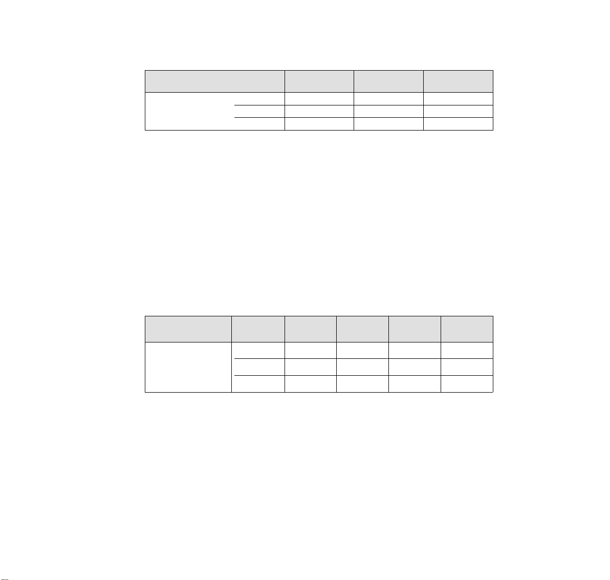
Setting the form length to 72 lines
Escape Sequence ESC C <n>
Transfer ASCII ESC "C" "H"
hex. 1B 43 48
dec.276772
100 REM Sample for the ESC C <n> sequence in ASCII,
110 REM using form with 72 lines.
120 REM Please note, in ASCII-Syntax you can use ASCII values
130 REM equal or bigger codetable no. 32 only.
140 REM LPRINT CHR$(27);"C";"H": REM mixed syntax;
150 REM set form length up to 72 lines
160 REM The same sequence written in hexadecimal syntax
170 LPRINT CHR$(&H1B);CHR$(&H43);CHR$(&H48);
180 REM set form length up to 12 lines
190 REM The same sequence written in decimal syntax
200 LPRINT CHR$(27);CHR$(67);CHR$(72);
210 REM set form length up to 72 lines
Setting the form length to 12 inches
Escape Sequence ESC C NUL <n>
Transfer ASCII ESC "C" NUL FF
hex. 1B 43 00 0C
dec. 27 67 0 12
with n=72
with n=12
Introduction
4
100 REM Sample for the ESC C NUL <n> sequence in ASCII,
110 REM using form with 12 inch length.
120 REM Please note, in ASCII-Syntax you can use ASCII values
130 REM equal or bigger codetable no. 32 only.
140 REM LPRINT CHR$(27);"C";CHR$(0);CHR$(12): REM mixed syntax;
150 REM set form length up to 12 inch
160 REM The same sequence written in hexadecimal syntax
170 LPRINT CHR$(&H1B);CHR$(&H43);CHR$(&H0);CHR$(&HC);
180 REM set form length up to 12 inch
190 REM The same sequence written in decimal syntax
200 LPRINT CHR$(27);CHR$(67);CHR$(0);CHR$(12);
210 REM set form length up to 12 inch
Page 88
Paper and Text Formatting
Form Length in Lines
Form Length in Inches
Data Structure
Description
ASCII ESC "C" <n> set form length in lines
hex. 1B 43 <n>
dec. 27 67 <n>
ASCII ESC "C" <0> <n> set form length in inches
hex. 1B 43 0 <n>
dec. 27 67 00 <n>
This code sequence sets the form length to n times the current line feed pitch (in in-
➊
ches). Also the current print position is simultaneously defined as top of form.
The value specified for n must be an integer in the range of 1 to 127. This value is mul-
tiplied by the current line feed pitch to obtain the form length. For example, if 60 is
specified for n and the current line feed pitch is
ches. Once set by this sequence, the form length is not affected by changing the line
spacing. This code sequence is ignored if the value specified for n is not in the range
of 1 to 127.
This code sequence sets the form length to the number of inches specified by n. It
➋
also defines the current print position as top of form.
The value specified for n must be an integer in the range of 1 to 22; otherwise the se-
quence will be ignored.
ESC C
ESC C NUL
➊➌
➋➌
1
inch, the form length is set to 10 in-
⁄
6
This code sequence resets the perforation skip function (ESC N).
➌
Paper and Text Formatting
5
Page 89

Example 10 REM form length
20 FF$=CHR$(12)
30 K=1
40 LPRINT CHR$(27);"C";CHR$(4);
50 FOR F=1 TO 3
60 FOR L=1 TO K
70 LPRINT "length 4: form";F;"line";L
80 NEXT L
90 K=K+1
100 LPRINT FF$;
110 NEXT F
120 K=1
130 LPRINT CHR$(27);"C";CHR$(3);
140 FOR F=1 TO 3
150 FOR L=1 TO K
160 LPRINT "length 3: form";F;"line";L
170 NEXT L
180 K=K+1
190 LPRINT FF$;
200 NEXT F
210 END
Paper and Text Formatting
6
Page 90

Set Page Length in Units
ESC ( C
Data Structure
ASCII ESC "(" "C" <n
hex. 1B 28 43 <n
dec. 274067<n
Description Valid values:
n
= 2, nH = 0
L
0 < ((m
x 256) + mL) x (defined unit) ≤ 22
H
Defines page length in untis previously defined with the sequence ESC ( U (see page 62).
(page length) = ((m
(page length) x
m
= INT
H
m
= MOD
L
This sequence sets top and bottom margins to default.
x 256) + mL) x (defined unit)
H
256
(page length) x
256
><nH><mL><mH> set page length in units
L
><nH><mL><mH>
L
><nH><mL><mH>
L
1
(defined unit)
(defined unit)
1
Set page length first, then load paper. Using this sequence within the form sets top of
form position at the current position.
Paper and Text Formatting
7
Page 91

Set Page Format
ESC ( c
Data Structure
ASCII ESC "(" "c" <n
hex. 1B 28 63 <n
dec. 274099<n
Description Valid values:
n
= 4, nH = 0
L
((t
x 256) + tL) < ((bH x 256) + bL) top margin < bottom margin
H
((b
x 256) + bL) x (defined unit) ≤ 22 bottom margin < 22 inches
H
Defines top and bottom margins previously defined with the sequence ESC ( U
(see page 62).
(top margin) = ((t
(top margin) x
= INT
(top margin) x
t
H
t
= MOD
L
><nH><tL><tH><bL><bH> set page format
L
><nH><tL><tH><bL><bH>
L
><nH><tL><tH><bL><bH>
L
x 256) + tL) x (defined unit)
H
1
(defined unit)
256
(defined unit)
256
1
(top margin) = ((t
b
= MOD
H
= MOD
b
L
Paper and Text Formatting
8
x 256) + tL) x (defined unit)
H
(bottom margin) x
(bottom margin) x
256
256
1
(defined unit)
1
(defined unit)
Page 92

This sequence sets new top and bottom. it does not affect the current page length setting.
Set top and bottom margin first, then load paper. Using this sequence within the form
sets top margin at the current position.
Paper and Text Formatting
9
Page 93

Perforation Skip
ESC N
Reset Perforation Skip
Data Structure
Description
ASCII ESC "N" <n> set space before perforation (perforation skip)
hex. 1B 4E <n>
dec. 27 78 <n>
ASCII ESC "O" reset perforation skip
hex. 1B 4F
dec. 27 79
This code sequence enables the perforation skip function and sets the bottom margin
➊
(distance between the last print line of one page and the first print line of the following
page) to n lines. The value specified for n must be in the range of 1 to 127 and must
be smaller than the form length minus the top margin.
The printer automatically advances the paper to the first printable line of the next page
whenever the current print line falls within the margin area defined as n lines from the
bottom of the current page (n being the value specified for the bottom margin area).
The margin area before and after the perforation is n times the current line spacing.
Once this margin area has been defined, it will not be affected by changing the line
spacing and remains effective until the printer receives code sequence ESC O (reset
perforation skip), or until form length is changed by ESC C or ESC C 0.
This code sequence deselects the perforation skip function set by ESC N <n>.The bot-
➋
tom margin is set to 0 lines, thus disabling perforation skip. This results in continuous
printout, unless the software used in the computer defines the form length by counting
the printed lines.
ESC O
➊
➋
This function only applies for fanfold paper, not for cut sheet processing or with mounted
sheet feeder.
Paper and Text Formatting
10
Page 94

Example 10 REM skip
20 LPRINT CHR$(27);"C";CHR$(6);:REM form length
30 LPRINT CHR$(27);"N";CHR$(1);:REM set skip
40 FOR F=1 TO 2
50 FOR L=1 TO 5
60 LPRINT "form";F;" line";L
70 NEXT L:NEXT F
80 END
Paper and Text Formatting
11
Page 95

Right Margin
ESC Q
Left Margin
Data Structure
Description
ESC
ASCII ESC "Q" <n> set right margin
hex. 1B 51 <n>
dec. 27 81 <n>
ASCII ESC "
hex. 1B 6C <n>
dec. 27 108 <n>
Character
density
10 cpi
12 cpi
15 cpi
17.1 cpi
20 cpi
Values for n are valid for a line length of 8 inch (80 columns printer) or 13.6 inch
(136 columns printer) set in the menu.
The absolute margin position depends on whether enlarged print mode, compressed print
mode, Pica or Elite are selected. When using proportional spacing, the setting of the margins corresponds to the setting when in Pica font type (10 cpi).
The command for setting the margins must be given at the beginning of a line, all data of
the same line are lost in the print buffer.
" <n> set left margin
l
Values for n
80 columns
printer
1... 80
1... 96
1...120
1...136
1...160
136 columns
printer
1...136
1...163
1...204
1...232
1...255
➊
➋
l
The right margin is set to n columns, depending on the character density selected. As
➊
soon as the right margin is reached after this command has been given, a carriage return and a line feed are added to the characters to be printed.
The left margin is set to n columns, depending on the character density selected.
➋
Paper and Text Formatting
12
Page 96

Example 10 REM left and right margin
20 LPRINT " 1 2 3 4 5"
30 LPRINT "12345678901234567890123456789012345678901234567890123"
40 LPRINT CHR$(27);"l";CHR$(10);CHR$(27);"Q";CHR$(53);
50 LPRINT "Now the left margin is set to column 10 and";
60 LPRINT "the right margin is set to column 53."
70 LPRINT CHR$(27);"l";CHR$(5);CHR$(27);"Q";CHR$(41);
80 LPRINT "Now the left margin has been reduced";
90 LPRINT "to column 5 and the right margin has";
100 LPRINT "been set to column 41."
110 END
Paper and Text Formatting
13
Page 97

Justification and Centering
ESC a
Data Structure
Description
ASCII ESC "a" <n>
hex. 1B 61 <n> or n
dec. 27 97 <n> or n
In some cases it is necessary to center headlines or to have the text printed in a way that
left or right margin or both margins are justified. By means of this code sequence the printer automatically justifies the text.
Justification mode depends on the value selected for n:
0 (hex.00 or hex.30) left justification (default setting)
1 (hex.01 or hex.31) centered
2 (hex.02 or hex.32) right justification
3 (hex.03 or hex.33) left and right justification
The justification mode must always be set at beginning of the line.
Justification mode can be used in all print qualities.
If left and right justification is activated, the validity of codes ESC $, ESC\ and HT at
➊
the beginning of the line is checked.
Left and right justification is only achieved if the length of the data line (measured from
the start of data input up to a CR or LF code) fills 75% to 125% of the given printed
area.
At less than 75%, left and right justification justification is not achieved. If the length of
the printed line extends more than 25% outside of the printed area, left and right justification justification is carried out for the character spacing which comes closest to the
value of 100% within the printed area. The remaining data are printed in the next line.
➊
Paper and Text Formatting
14
Page 98

Example 10 REM justification and centering
20 WIDTH "LPT1:",255
30 LPRINT CHR$(27);"Q";CHR$(48);:REM set right margin
40 LPRINT CHR$(27);"a";CHR$(1);"CENTERED"
50 LPRINT "HEADLINE"
55 LPRINT CHR$(27);"a";CHR$(3)
60 LPRINT "Now the right and the left justification ";
70 LPRINT "is on. The lines are filled with blanks ";
80 LPRINT "until they are long enough to reach the ";
90 LPRINT "right margin."
100 LPRINT
110 LPRINT CHR$(27);"a";CHR$(2);"These lines are only"
120 LPRINT "justificated on the"
130 LPRINT "right margin."
140 LPRINT
150 LPRINT CHR$(27);"a";CHR$(0);"Now the default setting"
160 LPRINT "is selected again. The lines are"
170 LPRINT "justified on the left margin."
180 END
Paper and Text Formatting
15
Page 99

Character Spacing
Set HMI (Horizontal Motion Index)
Data Structure
Description Valid values:
ASCII ESC "c" <n
hex. 1B 63 <n
dec. 27 99 <n
0 ≤ n
≤ 4
H
0 ≤ n
≤ 255
L
0 < ((n
x 256) + nL)) ≤ 1080; HMI ≤ 3.00 inches
H
The normal print density is enlarged according this formula:
x 256) + nL
(n
= INT
H
360
HMI x 360
256
HMI x 360
256
HMI =
n
H
nL = MOD
><nH> set HMI (Horizontal Motion Index)
L
><nH>
L
><nH>
L
inch
ESC c
Character Spacing
16
Page 100

This sequence terminates previously set additional character space defined with
ESC SP.
Following sequences will cancel the HMI mode:
ESC ! print mode selection
ESC @ printer initialization
DC2 reset condensed print
DC4 reset enlarged print mode (set by <SO> or ESC <SO>)
ESC g character density 15 cpi
ESC M character density 12 cpi (Elite)
ESC P character density 10 cpi (Pica)
ESC p proportional spacing ON/OFF
ESC SP character spacing
ESC W continuous enlarged print mode ON/OFF
SI condensed print ON
SO enlarged print mode (automatically reset after one line)
Character Spacing
17
 Loading...