

Page 1
Administrator’s Manual
6800 Series Printer s
Page 2

READ THIS SOFTWARE LICENSE AGREEMENT BEFORE USING THIS PRINTER
Software License Agreement
CAREFULLY READ THE FOLLOWING TERMS AND CONDITIONS BEFORE USING THIS PRINTE R. USING THIS PRINTE R INDICATES
YOUR ACCEPTANCE OF THESE TERMS AND CONDITIONS. IF YOU DO NOT AGREE TO THESE TERMS AND CONDITIONS,
PROMPTLY RETURN THE PRINTER AND ALL ACCOMPANYING HARDWARE AND WRITTE N MATERIA LS TO THE PLACE YOU
OBTAINED THEM, AND YOUR MONEY WILL BE REFUNDED.
Definitions.
“Software” shall mean the digitally encod ed, machine-readable data and program. The term “Software Product” in clude s the Software
resident in the printer and its documentation. The Software Product is licensed (not sold) to you, and TallyGenicom. either owns or licenses
from other vendors who own, all copyright, trade secret, patent and other proprietary rights in the Software Product.
License.
1.
Authorized Use. You agree to accept a non-exclusive license to use the Software resident in the printer solely for your own customary
business or personal purposes.
2.
Restrictions.
a.
To protect the proprietary rights of TallyGenicom, you agree to maintain the Software Product and other proprietary information
concerning the typefaces in strict confidence.
b.
You agree not to duplicate or copy the Software Product.
c.
You shall not sublicense, sell, lease, or otherwise transfer all or any portion of the Software Product separate from the printer,
without the prior written consent of TallyGenicom.
d.
You may not modify or prepare derivative works of the Software Product.
e.
You may not transmit the Software Product over a network, by telephone, or electronically using any means; or reverse engineer,
decompile or disassemble the Software.
f.
You agree to keep confidential and use your best efforts to prevent and protect the contents of the Software Product from
unauthorized disclosure or use.
3.
Transfer. You may transfer the Software Product with the printer, but only if the recipient agrees to accept the terms and conditions of
this Agreement. Your license is automatically terminated if you transfer the Software Product and printer.
Limited Software Product Warranty
TallyGenicom warrants that for ninety (90) days after delivery, the Software will perform in accordance with specifications publi sh ed by
TallyGenicom. TallyGenicom does not warrant that the Software is free from all bugs, errors and omissions.
Remedy
Your exclusive remedy and the sole liability of TallyGenicom in connection with the Software is replacement of defective software with a copy
of the same version and revision level.
Disclaimer of Warranties and Limitat ion of Remedies
1.
THE PARTIES AGREE THAT ALL OTHER WARRANTIES, EXPRESS OR IMPLIED, INCLUDING WARRA NTIE S OF
FITNESS FOR A PARTICULAR PURPOSE AND MERCHANTABILITY ARE EXCLUDED. TallyGenicom does not warrant that
the functions contained in the Software will meet your requirements or that the operation of the Software will be uninterrupted
or error free. TallyGenicom reserves the right to make changes and/or improvements in the Software w ithout notice at any
time.
2.
IN NO EVENT WILL TALLYGENICOM BE LIABLE FOR LOST PROFITS, LOST DATA, BUSINE S S INTERRUP TIONS, OR
ANY OTHER DIRECT, INDIRECT, INCIDENTAL OR CONSEQ UENTI A L DAMA GES ARIS ING OUT OF THE USE OF OR
INABILITY TO USE THIS PRODUCT, EVEN IF TALLYGENICOM HAS BEEN ADVISED OF THE POSSIBILITY OF SUCH
DAMAGES, OR ANY DAMAGES CAUSED BY THE ABUSE OR MANIPULATION OF THE SOFTWARE. SOME STATES DO
NOT ALLOW THE EXCLUSION OR LIMITATION OF LIABILITY FOR CONSEQUENTIAL OR INCIDENTAL DAMAGES, SO
THE ABOVE LIMITATION MAY NOT APPLY TO YOU.
3.
TallyGenicom will not be liable for any loss or damage caused by delay in furnishing a Software Product or any other
performance under this Agreement.
4.
Our entire liability and your exclusive remedies for our liability of any kind (including liability for negligence except liability for
personal injury caused solely by our negligence) for the Software Product covered by this Agreement and all other
performance or nonperformance by us under or related to this Agreement are limited to the reme dies specified by this
Agreement.
5.
California law governs this Agreement.
Termination of License Agreement
This License shall continue until terminated. This license may be terminated by agreement between you and TallyGenicom or by
TallyGenicom. If you fail to comply with the term s of this Licen se and su c h failur e is not corre cted within thirty (30) days after notice.
When this License is terminated, you shall return to the pla ce you obta ined them, the printer and all copies of the Software and
documentation.
U.S. Government Restricted Rights
Use, duplication or disclosure by the Government is subject to restrictions as set forth in the Rights in Technical Data and Computer
Software clause at FAR 242.227-7013, subdivision (b) (3) (ii) or subparagraph (c) (1) (ii), as appropriate. Further use, duplication or
disclosure is subject to restrictions applicable to restricted rights software as set forth in FAR 52.227-19 (c) (2).
Page 3

Acknowledgement of Terms and Conditions
YOU ACKNOWLEDGE THAT YOU HAVE READ THIS AGREEMENT, UNDERSTAND IT, AND AGREE TO BE BOUND BY ITS
TERMS AND CONDITIONS. NEITHER PARTY SHALL BE BOUND BY ANY STATEMENT OR REPRESENTATION NOT
CONTAINED IN THIS AGREEMENT. NO CHANGE IN THIS AGREEMENT IS EFFECTIVE UNLE SS WRITTE N A ND SIGNED BY
PROPERLY AUTHORIZED REPRESENTATIVES OF EACH PARTY. BY USING THIS PRINTE R, Y O U AGREE TO ACCEPT THE
TERMS AND CONDITIONS OF THIS AGREEMENT.
This document contains proprietary information protected by copyright. No part of this document
may be reproduced, copied, translated, or incorporated in any other material in any form or by any
means, whether manual, graphic, electronic, mechanical, or otherwise, without the prior written
consent of TallyGenicom.
TallyGenicom makes no representations or warranties of any kind regarding this material, including,
but not limited to, implied warranties of merchantability and fitness for a particular purpose.
TallyGenicom shall not be held responsible for errors contained herein or any omissions from this
material or for any damages, whether direct or indirect, incidental or consequential, in connection
with the furnishing, distribution, performance, or use of this material. The information in this manual
is subject to change without notice.
COPYRIGHT 2013 PRINTRONIX, LLC.
Trademark Acknowledge ments
IBM, AS/400, and Proprinter are registered trademarks, and Intelligent Printer Data Stream and IPDS are
trademarks of International Business Machines Corporation.
Printronix, PGL, LinePrinter Plus, and IGP are registered trademarks, and 6805, 6810, 6805Z, 6810Z,
6805Q, 6810Q, 6815Q, 6820Q, and SureStak are trademarks of Printronix, LLC.
ANSI is a registered trademark of the American National Standards Institute, Inc.
Centronics is a registered trademark of Genicom Corporation.
CSA is a registered certification mark of the Canadian Standards Association.
Dataproducts is a registered trademark of Dataproducts Corporation.
EIA is a registered service mark of the Electronic Industries Association.
Epson is a registered trademark of Seiko Epson Corporation.
Ethernet is a trademark of Xerox Corporation.
IEEE is a registered service mark of the Institute of Electrical and Electronics Engineers, Inc.
QMS is a registered trademark, and Code V is a trademark of Quality Micro Systems, Inc.
TallyGenicom brand is owned by Printronix, LLC.
TUV is a registered certification mark of TUV Rheinland of North America, Inc.
UL is a registered certification mark of Underwriters Laboratories, Inc.
Page 4

Table of Contents
Introduction .................................................................... 9
Printer Overview .................................................................................................. 9
TallyGenicom 6800 Series Cartridge Ribbon Printers (CRP) ....................... 9
Consumable Monitoring with PrintNet Enterprise ............................................. 10
Protocols and Emulations .................................................................................. 10
Taking Care of your Printer ............................................................................... 11
Conventions in this Manual ............................................................................... 11
Warnings and Special Information .................................................................... 11
Related Documents ........................................................................................... 11
Setting Up The Printer ................................................. 13
Before You Begin .............................................................................................. 13
Power Requirements ......................................................................................... 13
Select a Site ...................................................................................................... 13
Printer Dimensions ............................................................................................ 14
Printer Component Locations ............................................................................ 17
Operating The Printer .................................................. 19
Powering on the Printer ..................................................................................... 19
Operating Modes ............................................................................................... 19
The Control Panel .............................................................................................. 20
Control Panel Keys ..................................................................................... 21
Cancel a Print Job ....................................................................................... 23
Operational Procedures ..................................................................................... 23
Reload Paper .............................................................................................. 23
Unload Paper .............................................................................................. 30
Integrated Print Management System ............................................................... 31
Output Darkness ......................................................................................... 32
Loading a Used Ribbon Cartridge .............................................................. 32
Lighter Or Darker Print ................................................................................ 32
Changing Ribbon Cartridge ........................................................................ 32
Configuration Menus .................................................... 37
Configuration Overview ..................................................................................... 37
Changing Parameter Settings ..................................................................... 37
Saving Parameter Settings ......................................................................... 37
Default and Custom Configur atio ns ............................................................ 37
Navigating the Menus ................................................................................. 38
Top Level Menu Overview ................................................................................. 39
Changing Parameters Example .................................................................. 40
Auto Save Configuration ............................................................................. 42
Page 5

Saving Your New Configuration .................................................................. 42
6800 CRP Main Menu ....................................................................................... 48
Quick Setup ....................................................................................................... 49
Operator Menu .................................................................................................. 51
Font Submenu ............................................................................................ 52
Forms Submenu ......................................................................................... 57
Vertical Format Units (VFU) Submenu ....................................................... 61
Config Menu ...................................................................................................... 62
Printer Submenu ......................................................................................... 62
Codes Submenu ......................................................................................... 65
Graphics Submenu ..................................................................................... 69
Configurations Submenu ............................................................................ 73
Host Interface Submenu ............................................................................. 75
USB I/O Submenu ...................................................................................... 76
Serial I/O Submenu ..................................................................................... 77
Parallel I/O Submenu .................................................................................. 80
Intellifilter Submenu .................................................................................... 81
Main File Mgmt Submenu ........................................................................... 82
SD File Mgmt Submenu .............................................................................. 83
CST/PAA Submenu .................................................................................... 84
PTX_SETUP Option Submenu ................................................................... 84
TCP/IP Menu ..................................................................................................... 84
Ethernet Address ........................................................................................ 85
Ethernet Params ......................................................................................... 86
Test Menu .......................................................................................................... 87
Pattern Submenu ........................................................................................ 88
Fault Override Submenu ............................................................................. 89
Diag Submenu ............................................................................................ 90
Interfaces ..................................................................... 91
Overview ............................................................................................................ 91
RS-232 Serial Interface ..................................................................................... 93
USB ................................................................................................................... 94
Centronics Parallel Interface ............................................................................. 94
Centronics Parallel Interface Signals .......................................................... 95
IEEE 1284 Parallel Interface ............................................................................. 95
Compatibility Mode ..................................................................................... 95
Nibble Mode ................................................................................................ 95
Byte Mode ................................................................................................... 95
Signals ........................................................................................................ 95
Ethernet ............................................................................................................. 97
Reprogramming the Security Key ................................ 99
Reprogramming the Security Key ..................................................................... 99
Page 6

How to Program the Security Key ............................................................... 99
Downloading Firmware .............................................. 101
Firmware File Types (.prg) and (.exe) ............................................................. 102
WebPanel Download ....................................................................................... 102
Automatic Download (.exe) ............................................................................. 105
Manual Two-Key Download Sequence ........................................................... 107
Manual Three-Key Download Sequence......................................................... 107
Sending Firmware in Download Mod e ............................................................ 108
Sending Firmware via Ethernet (FTP) ...................................................... 108
Sending Firmware via USB ....................................................................... 109
Sending Firmware via Parallel .................................................................. 113
Sending Firmware via Serial ..................................................................... 113
Downloading Files to the Main File System .................................................... 114
Filename Extensions Not Shown in Menus ..................................................... 114
WebPanel File Download ................................................................................ 115
PTX_SETUP Download................................................................................... 116
Manual Two-Key Download ............................................................................ 116
Downloading Files to the SD Card .................................................................. 117
Demo Facility ................................................................................................... 117
Downloading a Demo File ......................................................................... 117
Configuring the Printer to run a Demo File ............................................... 118
Starting a Demo File ................................................................................. 118
Pausing a Demo File ................................................................................. 118
Stopping a Demo File ............................................................................... 118
Deleting a Demo File ................................................................................ 118
Troubleshooting ......................................................... 119
Cleaning Requirements ................................................................................... 119
Exterior Cleaning ...................................................................................... 119
Interior Cleaning ........................................................................................ 119
Diagnosing Problems ...................................................................................... 121
Bar Code Verification ................................................................................ 121
Printing a Hex Dump ................................................................................. 122
Most Frequent Problems and Solutions .......................................................... 124
Diagnostics for EXX, BAD NVM, or ILL NVM Errors ....................................... 124
Fault Messages ......................................................................................... 125
Printer Specifications ................................................. 143
Ribbon Cartridge Specifications ...................................................................... 143
Paper Specifications ........................................................................................ 143
Labels .............................................................................................................. 143
Printer Weight and Dimensions ....................................................................... 144
Environmental Characteristics ......................................................................... 144
Page 7

Acoustic Noise Level ....................................................................................... 144
Electrical Characteristics ................................................................................. 145
Interfaces .................................................................................................. 145
Printing Speed ................................................................................................. 145
ASCII Character Set .................................................. 147
Zero Tear Pedestal Printer ......................................... 149
Overview .......................................................................................................... 149
Operation ......................................................................................................... 149
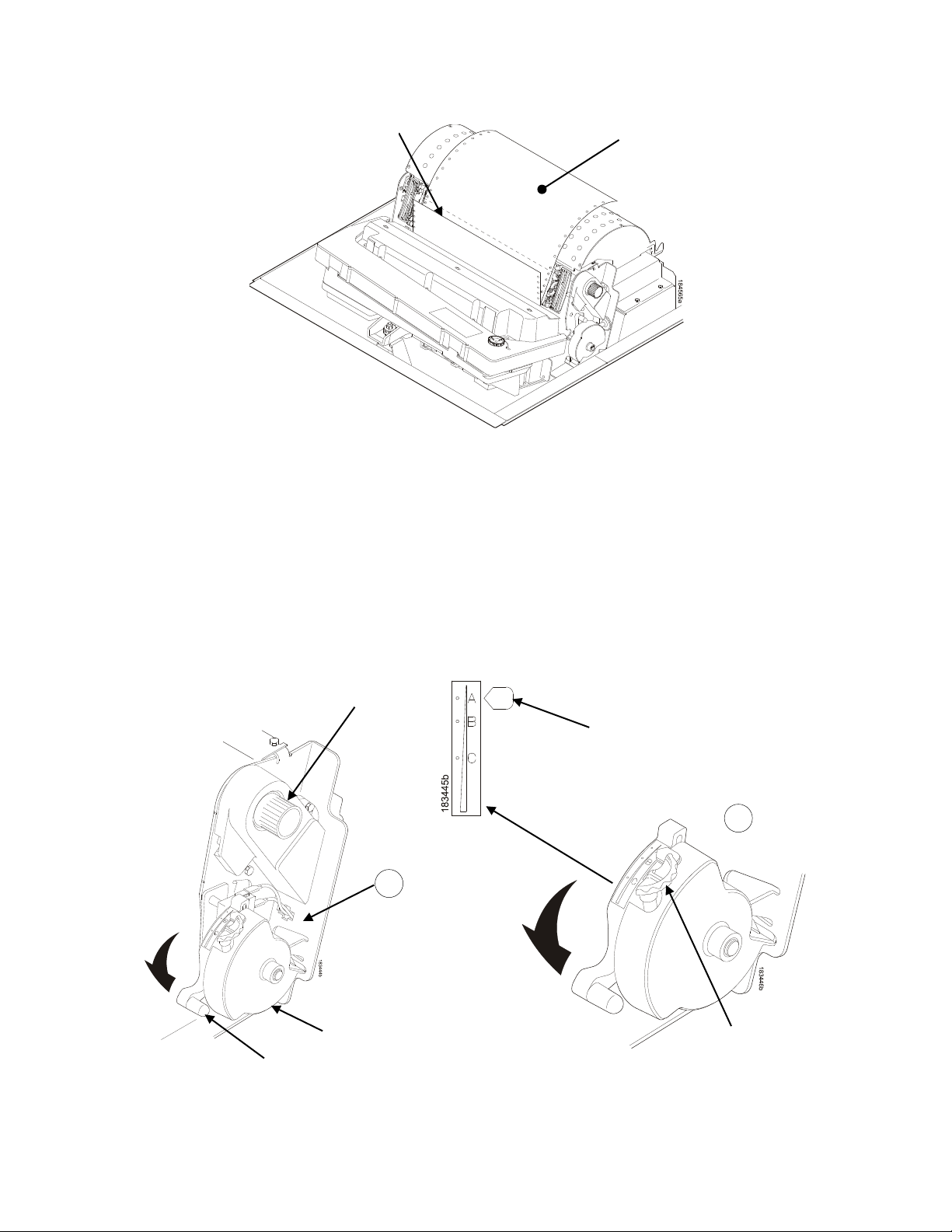
Position the Paper Input and Adjust the Paper Guides ............................ 149
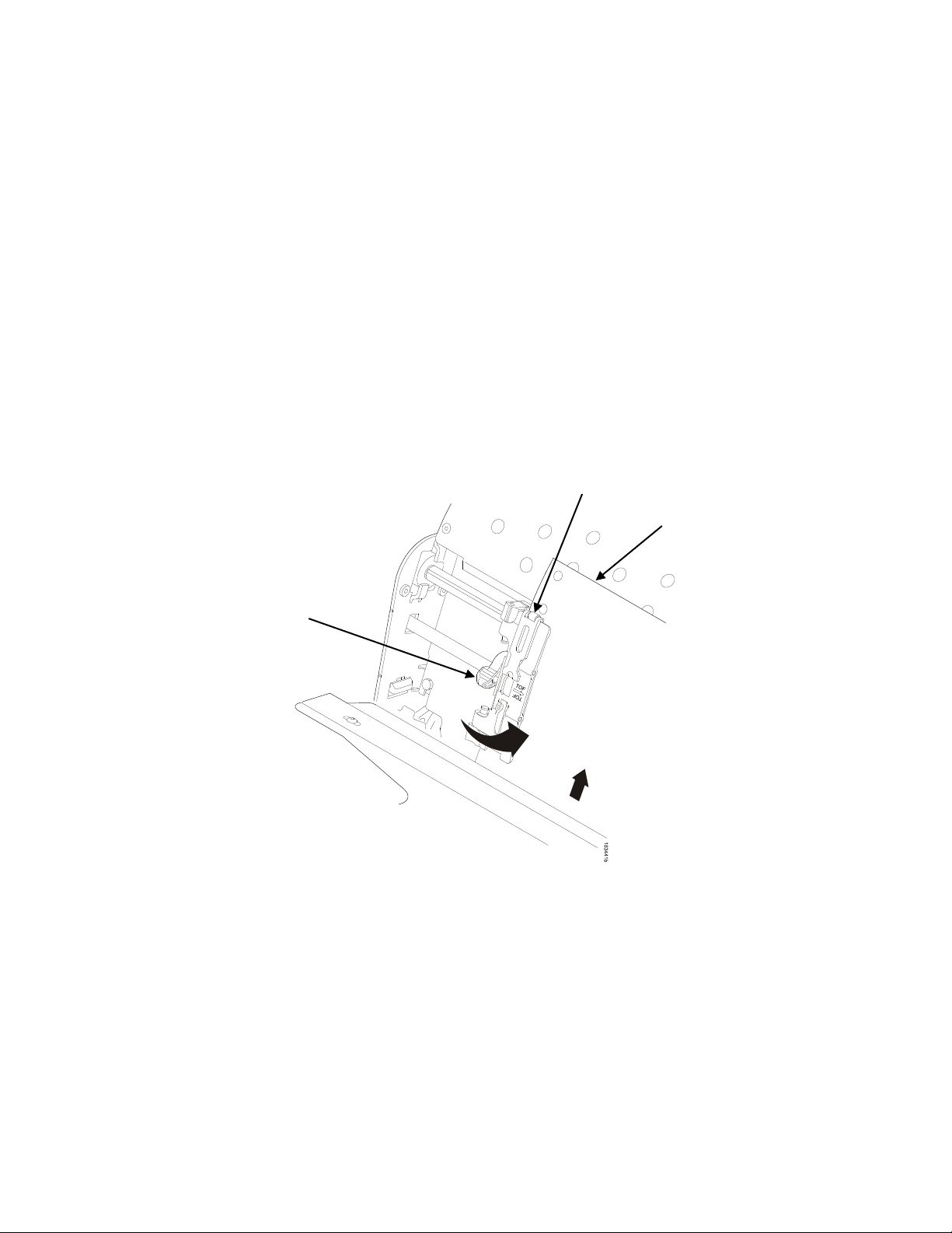
Load Paper................................................................................................ 151
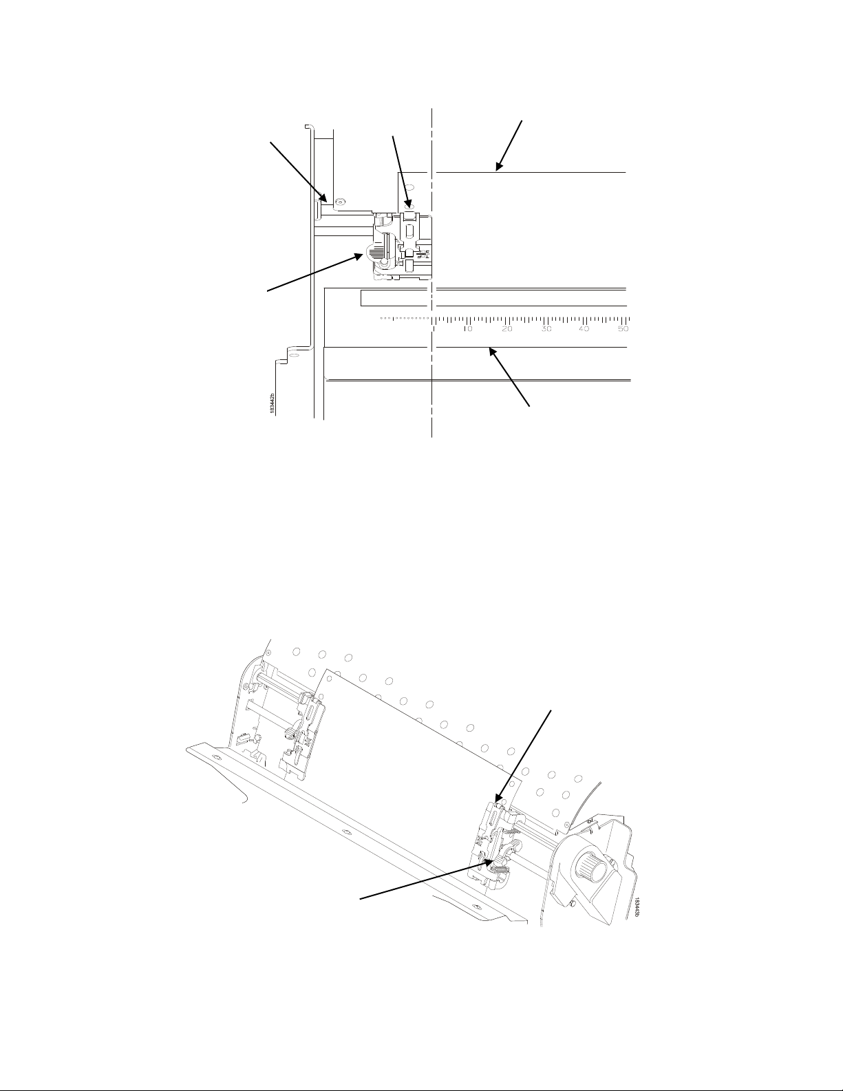
Position the Paper Out Sensor ................................................................. 153
Set the Tear Bar Distance ......................................................................... 154
ZTP SETTINGS Menu ..................................................................................... 156
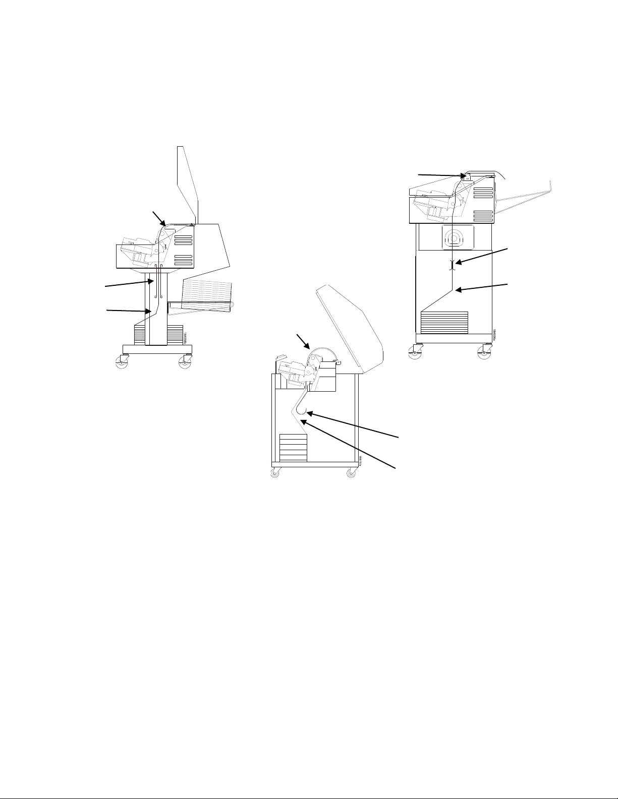
Performance Considerations ........................................................................... 157
How to Set the ZTP Printer to Help Mitigate Paper Jams ........................ 158
Quick Change Memory Card (QCMC) ....................... 159
Overview .......................................................................................................... 159
Installing the QCMC ........................................................................................ 160
Saving the Printer’s Configuration to the QCMC ............................................. 161
Copying the QCMC “Snapshot” Image to a Second Printer............................ 162
PTX_SETUP Commands ........................................... 165
Overview .......................................................................................................... 165
The PTX_SETUP Commands ......................................................................... 165
Commands ................................................................................................ 165
Customer Support ...................................................... 171
TallyGenicom Customer Support Center ........................................................ 171
TallyGenicom Supplies Department ......................................................... 171
Corporate Offices ...................................................................................... 172
Communication Notices ............................................. 173
Notices ............................................................................................................. 173
Communication Statements ............................................................................ 174
Software License Agreement .......................................................................... 179
Page 8

Page 9
Introduction
Printer Overview
This chapter provides a general overview of your printer and the conventions used within this manual.
TallyGenicom 6800 Series Cartridge Ribbon Printers (CRP)
TallyGenicom® is pleased to announce the TallyGenicom 6800™ Series Line Matrix printers, the latest
generation product from a long heritage of high quality extending over 30 years. TallyGenicom® is a
global leader for design and manufacturing with the ability to deliver unsurpassed service and support.
The TallyGenicom 6800™ Line Matrix Printing Platform extends the series of technology innovations that
cement TallyGenicom’s reputation of world class printing. Line matrix printing is TallyGenicom’s flagship
technology, and it remains the workhorse solution for supply-chain and back-office printing applications
because of its reliability, lower cost of ownership and flexibility of printing applications.
• Most reliable printer ever – Durability provides more up time and lower operating costs
• High capacity ribbon cartridge – Darker, easy to read images, last longer, and costs less to operate
than other print technologies
• Integrated print management system – provides precise control over print quality, print costs, and job
planning
• Cabinet, pedestal, or zero tear pedestal (ZTP) styles – best user access and forms handling flexibility
• Unsurpassed ease of use – larger graphics LCD simplifies operation and enhances productivity
Table 1 6800 Series Models and Configurations
Number Model
LMPPLS
(Line Matrix Printer Pedestal Low Speed)
LMPCLS
(Line Matrix Printer Cabinet Low Speed)
Configuration
Number
6805 500
6805Z 500
6810 1000
6810Z 1000
6810Q 1000
Print Speed (Lines
per Minute)
LMPCHS
(Line Matrix Printer Cabinet High Speed)
6815Q 1500
6820Q 2000
9
Page 10

Five printer configurations are available:
Cabinet (68XXQ)
• The enclosed cabinet models provide for near silent operation, making these printers perfectly
suitable for use in the quietest of office environments.
• Provides the best paper handling for large print runs. All paper input and outp ut i s contai ned insi de
the cabinet and protected from bumping and contamination.
• Highly effective combination of moveable fences and chains allows for precise stacking all the way up
to a full box of paper.
• Available in the following print speeds: 1000, 1500 and 2000 lpm models.
Pedestal (68XX)
• The pedestal model has a clamshell design that allows easy access to all controls providing faster
ribbon replacements and easier paper loading.
• Oversized casters are standard making movement easy.
• Available in the following print speeds : 500 and 1000 l pm models.
Zero Tear Pedestal (68XXZ)
• Special push tractor configuration enables printing from the very first to the very last line of a form and
then tear-off with no forms lost
• The elimination of wasted forms between jobs can yield significant savings.
• An ideal solution for supply-chain and back-office applications.
• Available in the following print speeds : 500 and 1000 l pm models.
Consumable Monitoring with PrintNet Enterprise
The Integrated Print Management System works with PrintNet Enterprise (PNE). PNE allows a system
administrator to remotely view the current consumable status of all printers. PNE can be configured to
deliver alerts on all consumable warnings. When a ribbon reaches the low state, PNE notifies the system
administrator remotely via an automated e-mail alert of the low condition. This allows corrective action to
be taken before the ribbon reaches its end of life. If the ribbon is not changed, an alert will again be
initiated once the ribbon reaches the 0% end point. Refer to your PrintNet Enterprise Remote
Management Software manual for details.
Protocols and Emulations
A protocol is a set of rules governing the exchange of information between the printer and its host
computer. These rules consist of codes that manipulate and print data and allow for machine-to-machine
communication. A printer and its host computer must use the same protocol. As used in this manual,
protocol and emulation mean the same thing.
Most impact printers use single ASCII character codes to print text, numbers, and punctuation marks.
Some characters, are defined as control codes. Control codes instruct the printer to perform specific
functions, such as underlining text, printing subscripts, setting page margins, etc. The difference between
most printer protocols is the characters used to create control codes and the ways in which these
characters are formatted.
When the printer executes the character and control codes of a particular printer protocol, it is emulating
that printer.
10
Page 11

Taking Care of your Printer
Your printer will produce high quality print jobs if it is well taken care of. Periodic cleaning, handling the
printer properly, and using the correct printer supplies such as ribbon and paper ensures optimum
performance. Chapter 8 explains how to clean the printer, and printer supplies are listed in Appendix A.
Conventions in this Manual
Control panel keys and indicators are highlighted in UPPERCASE BOLD PRINT.
Example: Press the CANCEL key, then press the ONLINE key.
Quotation marks (“ ”) indicate messages on the Liquid Crystal Display (LCD).
Example: Press the ONLINE key. “OFFLINE” appears on the LCD.
The + (plus) symbol represents key combinations.
Example: “Press + ” means press the (UP) key and the (DOWN) key at the same time.
Warnings and Special Information
Read and comply with all information highlighted under special headings:
WARNING A warning notice calls attention to a condition that could harm you.
CAUTION A caution notice calls attention to a condition that could damage the printer.
IMPORTANT Information vital to proper operation of the printer.
NOTE: A note gives you helpful tips about printer operation and maintenance.
Related Documents
• Quick Reference Guide — Explains how to set up the printer for basic operation (load ribbon cartridge
and media, and clear paper jams).
• Maintenance Manual — Explains how to maintain and repair the line matrix printer at the field service
level of maintenance.
• Integrated Network Interface Card User’s Manual
Information about network protocols, configuration, and network operation.
• 6800 Series Printers Emulations App l icati ons Manu al, Vol um e 1
Defines printer emulations.
• 6800 Series Printers Fonts and Character Sets App lic a tions Man ua l, Volume 3
Defines printer fonts and character sets.
• 6800 Series Printers Graphics Languages Applications Manual, Volume 4
Defines Code V, PGL, and MT660 IG printer graphics languages.
11
Page 12

12
Page 13

Setting Up The Printer
Before You Begin
Read this chapter carefully before installing and operating the printer. The printer is easy to install.
However, for your safety and to protect valuable equipment, perform all the procedures in this chapter in
the order presented.
Power Requirements
The printer must be connected to a power supply outlet that supplies 90 to 264 volts AC at its upper and
lower limits. These limits take into account normal voltage sags and surges created on the nominal line
voltage by other AC power loads associated with the AC distribution line. The printer automatically
senses and adjusts itself to conform to the correct voltage range.
Primary circuit protection is provided by the AC source protection device. Consult an electrician if printer
operation affects local electrical lines.
IMPORTANT Pri nter p ower should be supplied from a separate AC circuit protected at 20
amperes maximum for 100 - 240 volts at 50 or 60 Hertz.
Select a Site
Select a printer site that meets all of the following requirements:
• Permits complete opening of the printer cover and doors.
• For cabinet models, allows at least three feet of clearance behind the printer. (This permits air to
circulate freely around the printer and provides access to the paper stacking area.)
• For pedestal models, DO NOT place the side of the printer (inlet and exit air vents) against a wall or
other object. A minimum of 6 inch spacing is recommended.
• Has a standard power outlet that supplies 100-135 Volts AC or 178-240 Volts AC power, at 47 to 63
Hz.
• Is relatively dust-free.
• Has a temperature range of 10° C to 40° C (50° F to 104° F) and a relative humidity from 15% to 90%
non-condensing.
• Is located within the maximum allowable cable length to the host computer. This distance depends on
the type of interface you plan to use, as shown in Table 2.
13
Page 14
41.0 in
27.0 in
(68.6 cm)
27.0 in
83.0 in
(210.8 cm)
29.0 in
27.0 in
(68.6 cm)
Table 2 Maximum Interface Connection Cable Length
Interface Type Maximum Cable Length
Centronics Parallel 5 meters (15 feet)
IEEE 1284 Parallel 10 meters (32 feet)
Serial RS-232 15 meters (50 feet)
USB 2.0 Universal Serial Bus 5 meters (15 feet)
Twisted Pair / Type 3 300 meters (985 feet)
Ethernet 10/100Base-T 100 meters (328 feet)
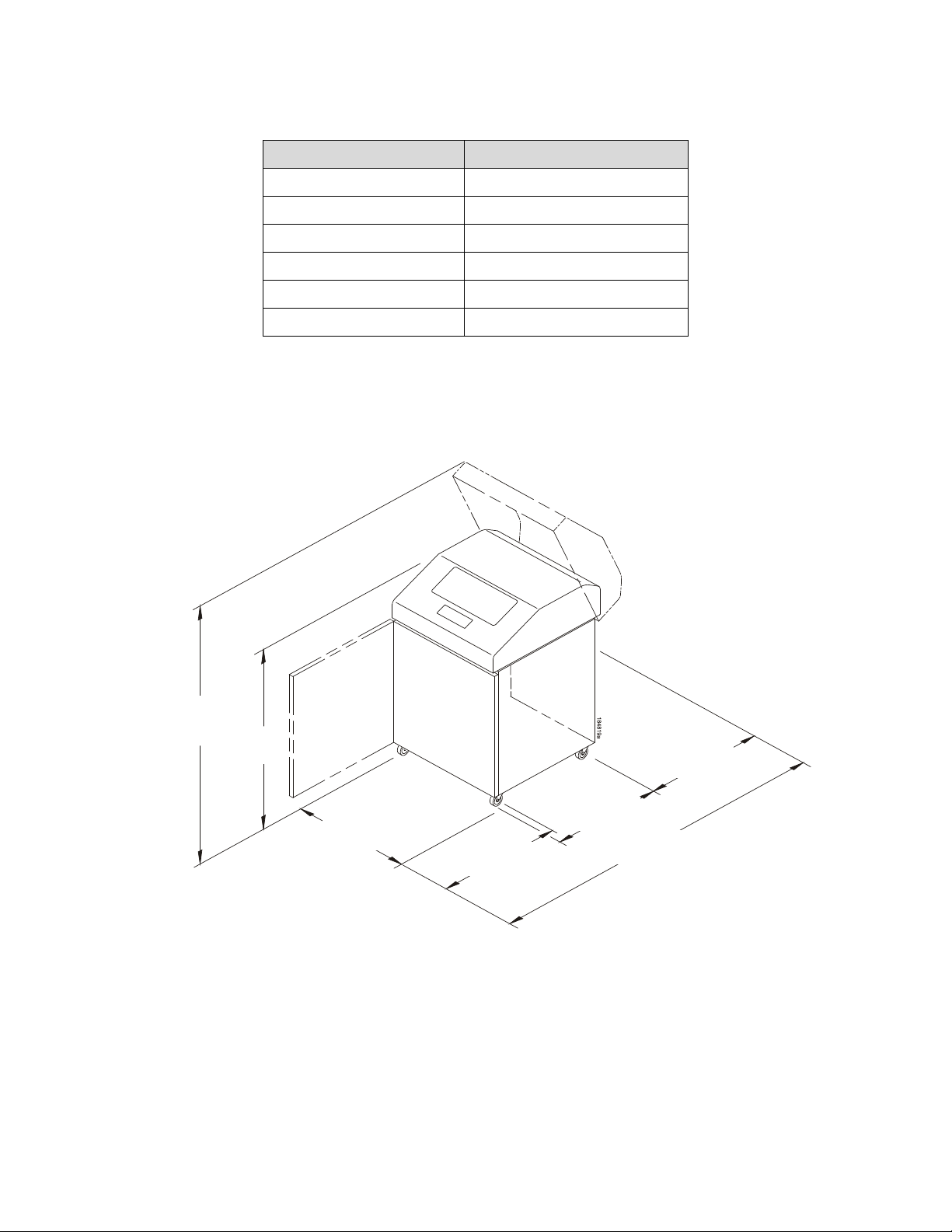
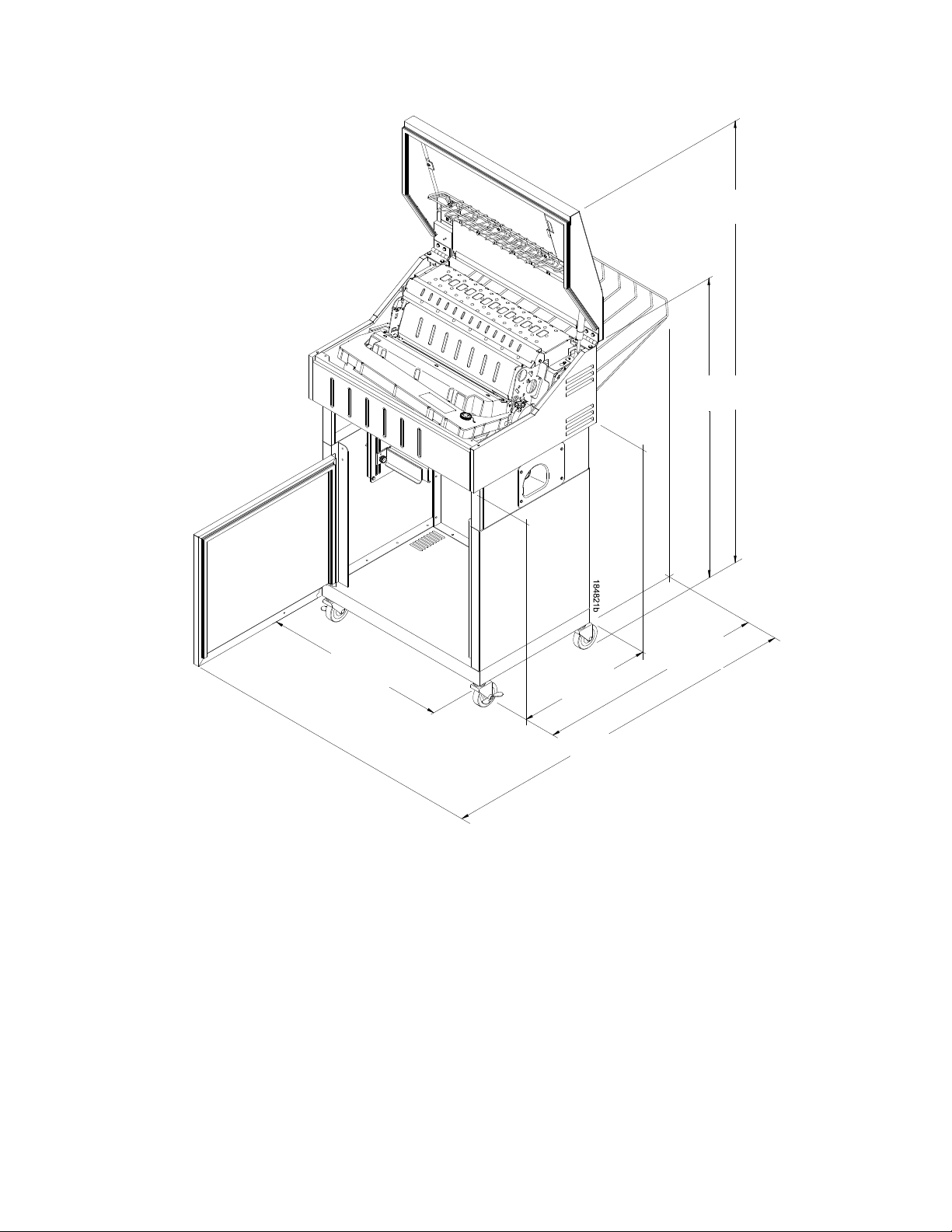
Printer Dimensions
57.5 in
(146.1 cm)
(104 cm)
(73.7 cm)
(68.6 cm)
Figure 1 Cabinet Model
14
Page 15
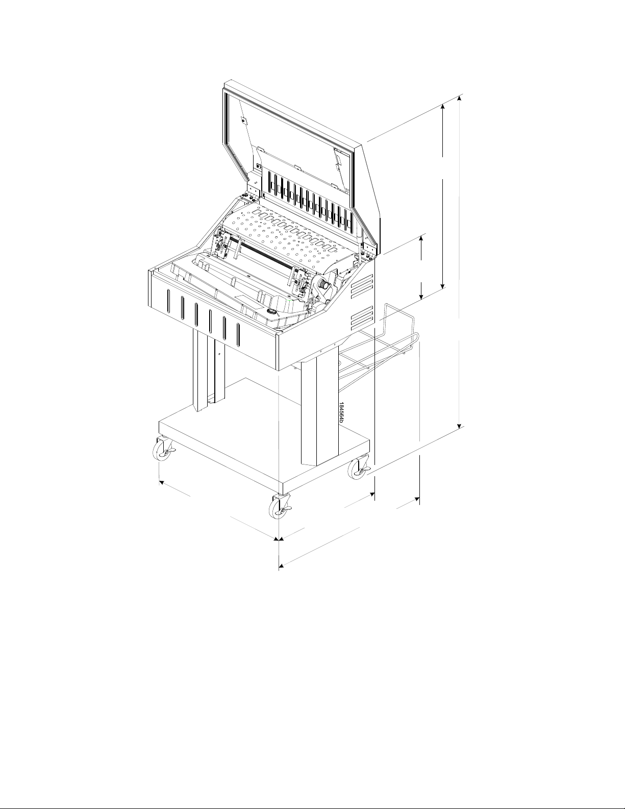
54.0 in
(28.9 cm)
29.5 in
(74.93 cm)
29.1 in
(73.9 cm)
19.1 in
(48.5 cm)
25.92 in
(65.8 cm)
11.36 in
(137.2 cm)
Figure 2 Pedestal Model
15
Page 16
38.9 in
(98.8 cm)
19.1 in
(43.8 cm)
31.95 in
(81.2 cm)
25.92 in
(65.8 cm)
(106.7 cm)
60.1 in
(152.7 cm)
Figure 3 Zero Tear Pedestal Mode
42.0 in
16
Page 17
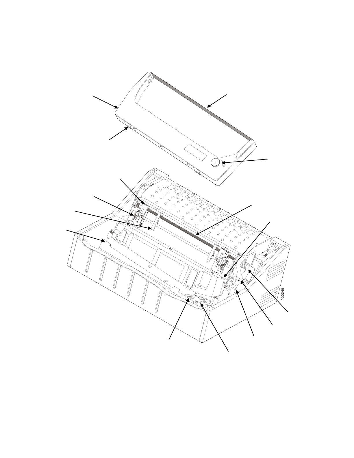
Ribbon
Cartridge
Tab (2)
Tractor (2)
Blue Tractor
Lock (2)
Paper
Support (2)
Tab Slot (2)
Ribbon Cartridge
Interface
Air Shroud
Assembly
Platen Stop
Platen Lever
Vertical Position
Knob
Hammerbank Cover
and Ribbon Mask
Splined Shaft
Ribbon
Tension Knob
Ribbon
Printer Component Locations
Figure 4 Printer Component Locations
17
Page 18

18
Page 19

Operating The Printer
Powering on the Printer
When you power on the printer, it executes a self-test. The default power-up state is offline. When the
self-test completes and the software has initialized successfully, the status indicator light is off, indicating
the printer is offline. When the printer is online, the default emulation type you have installed appears in
LCD display. The configuration name or ribbon life remaining is shown on the bottom of the LCD display.
If there is a fault during the self-test, the status indicator flashes and a specific fault message appears on
the display (such as “LOAD PAPER”). The alarm also sounds if it is configured to do so. See LCD
Message Troubleshooting Table on page 125 for information on fault messages and solutions.
Operating Modes
Online. In online mode, the printer can receive and print data sent from the host. Pressing the ONLINE
key toggles the printer from online to offline mode. The status indicator is lit in online mode.
Offline. In offline mode, you can perform operator functions, such as loading paper and setting top-of-
form. Pressing the ONLINE key toggles the printer from offline to online mode. The status indicator is off
in offline mode.
Menu. In offline mode, pressing ENTER moves the printer into Menu mode. In this mode, you can
navigate through all menus and change the printer configuration. To return to offline mode, press the
ONLINE key.
Fault. In fault mode, a condition exists which must be cleared before printing can continue. The status
indicator flashes, the alarm beeps (if configured to sound), and a descriptive fault message displays.
The current operating mode can be selected via control panel keys or can result from routine operations
such as powering on the printer.
19
Page 20
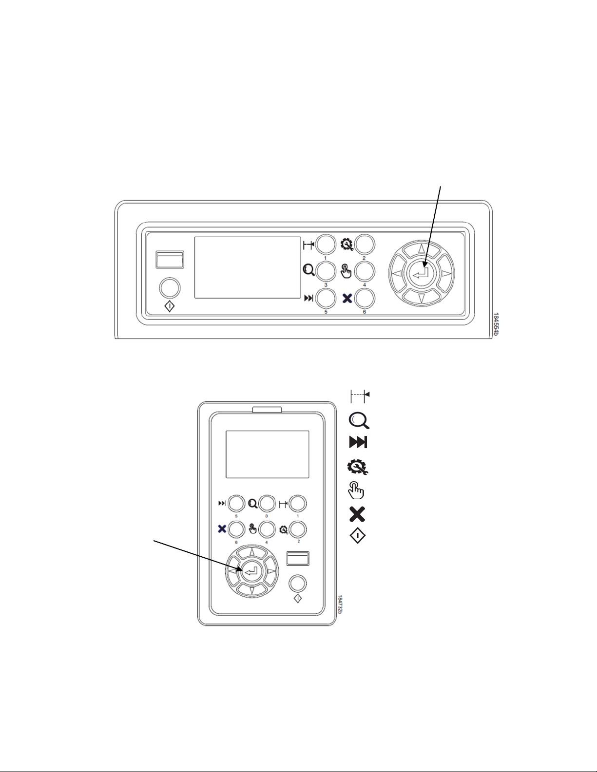
Enter
ENTER
TOF = Set TOF (Top of Form)
VIEW = View/Eject
ADVANCE = Paper Advance
CONFIG = Print Config
SELECT = Load Config/Print Mode
1
CANCEL = Cancel Job
ONLINE = Online/Clear
Legend:
The Control Panel
Figure 5 shows the keys, displays, and indicators as they appear on the control panel. The following
section provides the descriptions, and functions of the control panel keys.
Key combinations are indicated with the plus (+) sign. For example, “Press
key and the key at the same time.
Cabinet Model
Pedestal Model
Figure 5 Control Panel
NOTE:
1
Print Mode only available for H-Series printers.
+ ” means to press the
20
Page 21

Control Panel Keys
ONLINE
Toggles the printer between online and offline modes. The key performs the following in Online, Offline,
Fault, and Menu modes:
• Online Mode – sets the printer to Offline Mode.
• Offline Mode – sets the printer to Online Mode.
• Fault Mode – causes the printer to recheck the faults; if the faults are cleared, the printer toggles to
Offline Mode. If the fault condition is not corrected before pressing the ONLINE key, the fault
message reappears.
• Menu Mode – sets the printer to Offline Mode.
NOTE: When changing to Online Mode, if the user has changed menu items without saving the changes
in a configuration, the user will be prompted to save the changes.
ADVANCE
Performs advance to top-of-form, as defined by the current active form length. The key works both online
and offline.
• If online with data in the printer buffer, the data will print and then the paper will move to the next top-
of-form.
• In the fault state, pressing ADVANCE will advance the paper. The first press moves to the top of the
next available form. All subsequent presses advances one forms length as defined by the current
active forms length.
VIEW
When the printer is online or offline, pressing this key executes the view or eject function, depending on
whether the printer is a cabinet or a pedestal model.
If online with data in the printer buffer, the data prints and the key functions as described below.
If in a fault state, this key will be ignored.
• View Function — For cabinet and pedestal models, pressing the VIEW key for a short time (less
than 1/2 second) moves the last data printed to the tractor area for viewing. While in the view state,
the message "Printer in View" displays, pressing the UP or DOWN arrow keys moves the paper up or
down in 1/72 inch increments. This is done to align the image within a pre-printed form, for example.
Refer to the UP and DOWN key functions for additional details on the microstep feature. Pressing
VIEW a second time moves the paper back to the adjusted print position.
• Eject Function — For pedestal models only, if the View key is pressed for a long time (more than 1/2
second), the bottom of the last printed form will move to the tear bar position as set by the Tear Bar
Dist menu. The message "READY TO TEAR/EJECT To Return" displays. While in this position,
pressing the UP or DOWN arrow keys moves the paper up or down in 1/72 inch increments. Refer to
the Up and Down key functions for additional details on the microstep feature. When the VIEW key is
pressed a second time, the printer will move the paper either forward or backward to enable printing
on the next available form.
CANCEL
In offline mode, this key cancels all data in the print buffer. The print buffer is cleared without printing any
of the data and the current paper position moves to the next top-of-form. If this function is disabled, the
CANCEL key will be ignored.
21
Page 22

NOTE: Use of this key will cause loss of data.
TOF
Sets the top-of-form on the printer. This key is active only when the printer is offline and will not operate if
the printer is in a fault condition. The paper moves down to the print position and aligns to the top-of-form.
Refer to the User’s Setup Guide for com plete instr ucti ons on how to set the top-of-form.
CONFIG
In offline mode, CONFIG prints the current full configuration. This key requires a confirmation with the
ENTER key; pressing any other key will exit from this function. See Config Menu on page 62 for an
explanation of configuration menus.
SELECT
In offline mode, this key allows for fast selection of any of the previously stored configurations. Pressing
this key causes the printer to cycle through the following configuration load options: Factory, Cfg 1, Cfg 2,
Cfg 3,..., Cfg 8.
ENTER ( ↵ )
When navigating the configuration menus, the Enter key (referenced by the symbol ↵) selects the
currently displayed option value as the active value. An asterisk (*) appears next to the active value on
the display. ENTER is also used for starting and stopping printer tests and generating a configuration
printout.
NOTE: The ENTER key must be unlocked to execute the select function. See UP + DOWN, later in this
section.
• In Offline mode, pressing the Enter key places the printer in Menu mode. This will bring up a set of
icons to select.
• In Menu mode (at the icon menu level), pressing the Enter key moves down into the menu tree of the
highlighted icon.
• Within a menu tree: if the highlighted menu contains submenus instead of a selectable parameter,
pressing the Enter key will go into the submenu. If the highlighted menu is a display only menu, then
pressing the Enter key performs no function. If the highlighted menu has selectable parameters,
pressing the unlocked Enter key will select the displayed parameter. An asterisk (*) displays next to
the selected parameter.
• If the highlighted menu is an executable menu, pressing the unlocked Enter key will cause the
function associated with the executable menu to run. If the ENTER key is locked, pressing the Enter
key for highlighted menus that are executable or contain selectable parameters will cause the
message, THE
NOTE: Press the UP and Down keys at the same time to lock/unlock the
For special Network Address menus or String menus, pressing the Enter key will move down into a
special multiple segment setting menu. Exit this menu by pressing Enter again to save changes or Cancel
to exit without saving changes. This key is inactive in all other modes.
UP or DOWN ( or )
↵ KEY IS LOCKED, to display momentarily.
↵ key.
Moves up or down between levels in the configuration menus and makes vertical forms adjustment. In
Offline mode or after pressing VIEW, press or to adjust the paper up or down in 1/72 inch
increments for fine vertical forms alignment. When the printer is in Menu mode, press or to move
through levels in the configuration menus.
22
Page 23

UP + DOWN ( + )
Locks and unlocks the ENTER key.
PREV or NEXT ( or )
Moves between the options on the current level of configuration menu. In the configuration menu,
press to scroll backward or press to scroll forward through the menu selections on the same level.
PREV + NEXT ( + )
When both keys are pressed simultaneously, the printer will reset to the power-up configuration and reset
its internal state (in offline mode).
Ribbon Life Indicator
If the Panel Display menu is set to Ribbon Life, the bottom of the LCD displays the remaining life of the
currently installed ribbon. The default settings for this feature should match the requirements for most
applications; no special user setup is needed. If your particular application requires darker printing or can
tolerate lighter printing, the ribbo n end poi nt can be adj usted as appr o priat e. See Ribbon on page 51.
Cancel a Print Job
The procedure to cancel a print job depends on the printer emulation and your application software.
Contact your system administrator for additional information.
1. If the printer is online, press ONLINE to place the printer in offline mode.
2. From the host system, stop the print job.
NOTE: If the print job is not stopped from the host system before pressing CANCEL, the print job
continues with data missing when the printer returns to online mode. Exercise caution to prevent
unwanted data loss occurrences, as this function deletes unprinted data in the printer. This
function is active only in offline mode; the purpose of this function is to eliminate the necessity of
printing unwanted data when print jobs are canceled.
3. Press CANCEL.
4. Set the top-of-form. Refer to the Quick Reference Guide.
Operational Procedures
This section contains routine printer operating procedures on how to:
• reload paper
• unload paper.
Reload Paper
Do this procedure when “LOAD PAPER” displays. (This message occurs when the last
sheet of paper passes through the paper slot.) This procedure reloads paper without
removing the last sheet of the old paper supply, while retaining the current top-of-form
setting.
23
Page 24
Paper Slot
Wire Guide
(2)
Pedestal Model
Metal Paper Guide
(200
Paper Slot
Cabinet
Paper Slot
Wire Guide (2)
Zero Tear
Pedestal Model
Model
0 lpm only)
Figure 6 Paper Slot Location
1. Raise the printer cover. Raise the platen lever as far as it will go. (See Figure 4 on page 17 for the
location of the lever.)
NOTE: Do not open tractor doors or remove the existing paper.
2. Cabinet models: open the front door and align the paper supply with the label on the floor.
Pedestal models: place the paper supply on the floor of the printer, centered under the paper slot.
Zero Tear Pedestal models: open the front door and place the paper supply inside the printer, on
the floor of the cabinet.
3. Ensure the paper pulls freely.
4. Feed the paper up through the paper slot (see Figure 6). It may be easier to feed one corner of the
new paper up through the slot first. When this corner can be grasped from the top, rotate the paper
back to the normal position.
NOTE: If you are using thick, multi-part forms and are unable to load the new paper over the existing
paper, go to step 15.
5. Hold the paper to prevent it from slipping down and through the paper slot.
24
Page 25
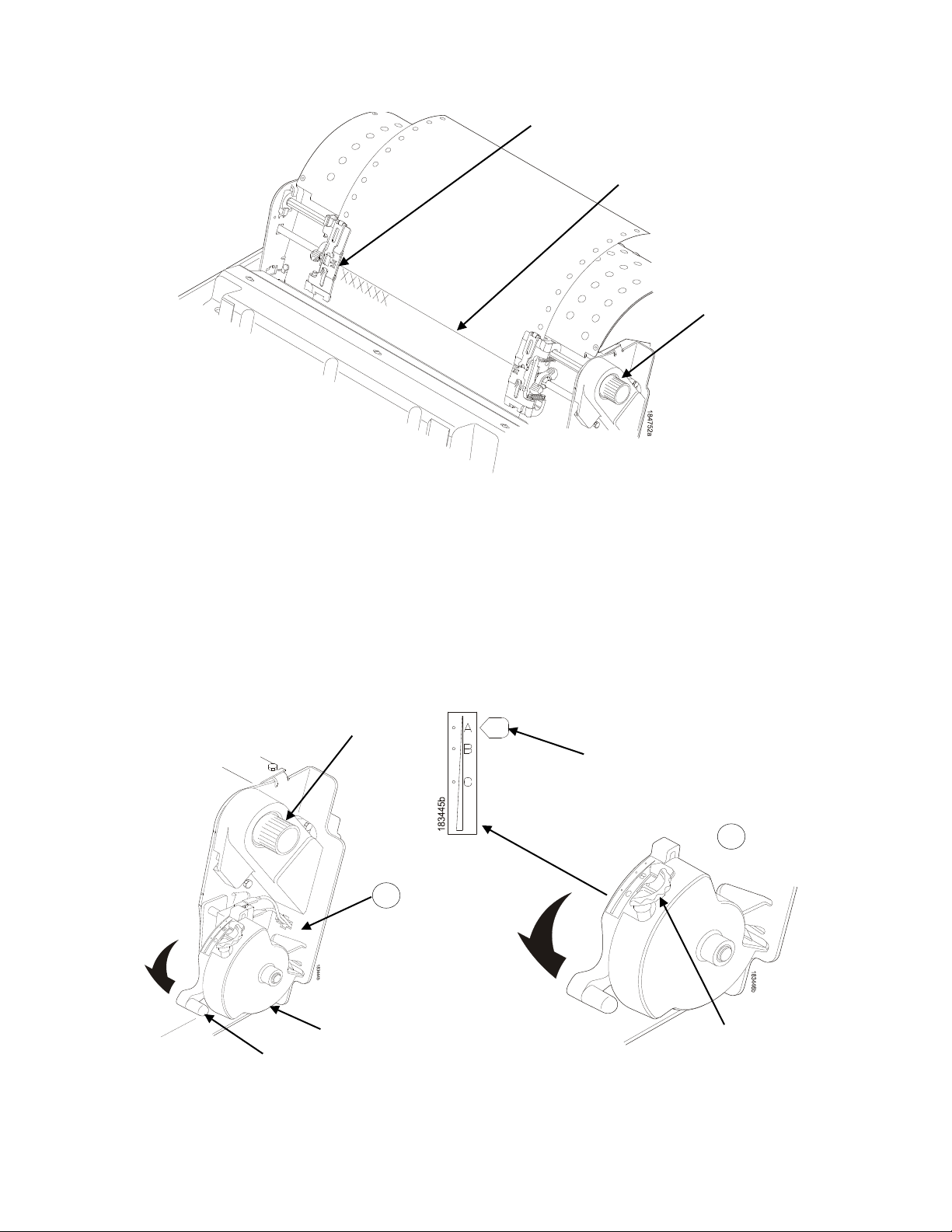
Vertical Position
Knob
Platen Lever
Platen Stop
Platen Stop
Knob
Paper Thickness
Indicator
New Paper
Existing Paper
Figure 7 Loading New Paper into the Printer
6. Pull the new paper above and behind the ribbon mask, but in front of the existing paper. See Figure 4
on page 17 for the ribbon mask location. If necessary, gently press the existing paper back.
7. Align the top edge of the new paper with the top perforation of the existing paper.
8. Load the new paper over the existing paper. Open and load the tractors one at a time to prevent the
paper from slipping.
NOTE: Make sure that the top edge of the new paper lines up with the top horizontal perforation of the
last page.
A
A
Figure 8 Setting the Platen Lever
25
Page 26
Left Tractor Lock
Paper
Left T
9. Turn the platen stop knob clockwise or counterclockwise to match the paper thickness. (The A-B-C
scale corresponds approximately to 1-, 3-, and 6-part paper thickness).
NOTE: If you are using the same thickness of paper, there is no need to readjust.
10. Lower the platen lever until it stops.
11. Press ONLINE to remove the “LOAD PAPER” fault message from the display.
12. Press ADVANCE several times to make sure the paper feeds properly beyond the tractors and over
the lower paper guide. Feed sufficient paper to ensure the paper stacks correctly.
13. Close the printer top cover. Close the cabinet front door.
14. Press ONLINE to place the printer in online mode and resume printing.
NOTE: Perform steps 15 to 31 only if you are unable to load the new paper over the existing paper.
15. Open both tractor doors.
16. Remove the old paper from the tractors. Allow the paper to fall into the paper supply area.
17. Feed the new paper up through the paper slot. Hold the paper to prevent it from slipping down
through the paper slot (see Figure 6 on page 24).
ractor Door
Figure 9 Loading Paper on the Left Tractor
18. Pull the paper above and behind the ribbon mask. See Figure 4 on page 17 for the ribbon mask
location.
19. Load the paper on the left tractor.
20. Close the tractor door.
26
Page 27
Tractor Splined
Shaft
Tractor Lock
Tractor
Paper
Paper Scale
Tractor Door
Tractor Lock
Figure 10 Positioning the Left Tractor to Avoid Damage
CAUTION To avoid damage to the printer caused by printing on the platen, always position
the left tractor unit directly to the left of the “1” mark on the paper scale.
21. Normally, you should not need to adjust the position of the left tractor. If adjustment is necessary,
unlock the left tractor by placing the tractor lock in the middle position. Slide the tractor until it is
directly to the left of the number “1” on the paper scale and lock it. (You can also use the paper scale
to count columns.)
Figure 11 Loading Paper onto the Sprockets
27
Page 28
Paper Slot
Cabinet Model
Upper Paper
Guide
Paper Slot
Wire Guide
Upper Paper
Guide
Paper Slot
Wire Guide (2)
Pedestal Model
Upper Paper
Guide
22. Unlock the right tractor.
23. Load the paper onto the sprockets and close the tractor door. If necessary, slide the right tractor to
remove paper slack or to adjust for various paper widths. Then, lock the tractor.
Zero Tear
Pedestal Model
(2)
Metal Paper Guide
(2000 lpm only)
Figure 12 Using the Paper Guide to Orient the Paper
24. Press ADVANCE several times to make sure the paper feeds properly beyond the tractors and over
the lower paper guide. Feed sufficient paper to ensure the paper stacks correctly.
25. Cabinet models: Open the cabinet rear door. Make sure the paper is aligned with the label in the
output area (inside the cabinet). Close the front and rear doors.
28
Page 29
TOF Indicator
Perforation
Vertical
Position Knob
Vertical Position
Knob
Platen Lever
Platen Stop
Platen Stop
Knob
Paper Thickness
Indicator
Figure 13 Aligning the Perforation with the TOF Indicator
26. Align the top of the first print line with TOF indicator on the tractor by rotating the vertical position
knob. For best print quality, it is recommended that the top-of-form be set at least one print line or
more below the perforation.
NOTE: For exact positioning, perform a short press of the VIEW key to move the last data printed to the
tractor area for viewing. While in View mode “Printer in View” displays. Press the Up or Down
Arrow keys to move the paper vertically in small increments. Pressing the VIEW key a second
time moves the paper back to the adjusted print position. The key works both online and offline
provided that the printer is in View mode. (This procedure is applicable for both the cabinet and
pedestal models.)
A
A
Figure 14 Adjusting the Platen Lever
29
Page 30
Paper
Perforation
27. Turn the platen stop knob clockwise or counterclockwise to match the paper thickness. (The A-B-C
scale corresponds approximately to 1-, 3-, and 6-part paper thickness. Adjust unti l you have the
desired print quality).
NOTE: The platen stop allows you to set an optimum and consistent thickness that is not affected when
opening and closing the platen lever.
28. Lower the platen lever until it stops.
29. Press ONLINE to clear any fault messages (such as “LOAD PAPER”) from the LCD.
30. Press TOF. The top-of-form you have set moves down to the print position. If there is data in the
buffer, the paper moves forward to the last print position on the next page.
31. Press ONLINE and close the printer cover.
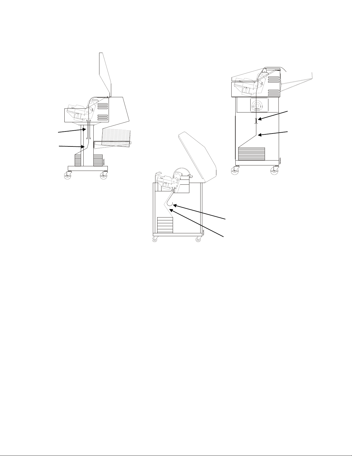
Unload Paper
1.
Press ONLINE to place the printer in offline mode and open the printer cover.
2.
For cabinet models, open the cabinet rear door.
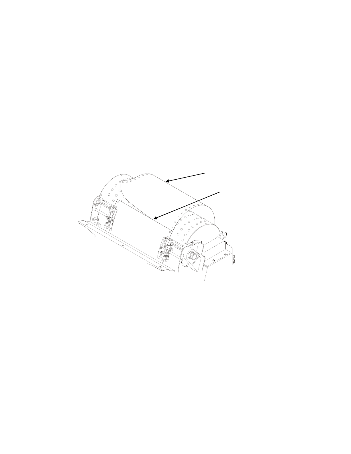
Figure 15 Unloading the Paper from the Printer
3.
Tear off the paper at t he pe r f or ation.
4.
Allow the paper to fall to the back of the printer and into the paper stacking area.
5.
For pedestal models, remove the stacked paper from the paper tray.
6.
For cabinet models, remove the stacked paper from the rear cabinet floor.
7.
Close the cabinet rear door.
30
Page 31

Tractor Door
Platen Lever
Figure 16 Completely Removing the Paper
8.
To completely remove the paper from the printer:
a.
Raise the platen lever as far as it will go and open both tractor doors.
CAUTION Be careful when pulling any paper backward through the paper path, especially
when using a label stock. If you are not careful, labels can detach and adhere to
the printer within the paper path, where only an authorized service representative
can remove them.
b.
Open the cabinet front door.
c.
Gently pull the paper down through the paper slot. Allow the paper to fall into the paper supply
area.
d.
Remove the paper from the paper supply area.
Integrated Print Management System
The 6800 CRP has a feature that automatically monitors and communicates the status of the ribbon life to
help the operator know when to change ribbons. Using an ink delivery system called the Cartridge Ribbon
System (CRS), the printer can automatically detect when a new or used ribbon is loaded, and all ribbon
properties. The ribbon is contained in a plastic box (the cartridge) and feeds only in one direction. The
CRS contains an interface board that allows communication between the printer and the cartridge. Using
the CRS, the 6800 automatically detects when a new or used ribbon is installed and determines the
ribbon’s length, ink color, and expected yield. The ribbon life, starting from 100% when new and
decreasing to 0% when depleted, can be displayed on the control panel if configured by the Panel Display
Menu. See Figure 5 on page 20.
When the ribbon life reaches 2%, a warning message “RIBBON UNDER 2%/ Change RBN soon” appears
on the control panel display. The control panel status indicator lamp flashes. The printer will continue
printing in this condition until the ribbon life reaches 0% at which time, printing will stop. The ribbon may
be changed at any time while the printer is in the “CARTRIDGE AT END POINT/Change Cart” condition
31
Page 32

without losing data in the printer’s buffer. If a new ribbon is loaded, the system automatically detects the
change, clears the condition when the platen is closed, and restarts the life at 100%. If a partially used
ribbon is loaded, the system continues the life at the percentage indicated for the used ribbon.
You may also resume printing for approximately two more minutes without changing the ribbon by
pressing the ONLINE key twice. This may be done as many times as needed to complete the job in
progress.
Ribbon usage information is calculated by maintaining a count of impressions (dots) that is stored on the
ribbon cartridge and updated periodically so that the cartridge can be used on a different printer with the
information intact. This allows the system administrator to have precise control over print quality and
consumable costs. The accurate presentation of available ribbon life allows for efficient planning of print
jobs. For example, if the displayed ribbon life were low, you can install a new ribbon before printing a
large print job.
Output Darkness
By default the system is configured to meet most user requirements. However, some applications require
that the output remains darker than the nominal set point while some applications are less critical and
could tolerate a lighter final image. The system can easily adjust to this variability. A setting under the
QUICK SETUP or FORMS menu is available that allows the user to adjust the final output. The range is
as follows:
Normal (Default)
Darker +1 through +6
Lighter -1 through -10
The ribbon life indicator always cycles between 100% and 0%, but if a darker setting is selected, zero will
be reached more quickly. If a lighter setting is selected, the system will extend the amount of printing it
takes to reach zero.
Loading a Used Ribbon Cartridge
You can take the ribbon cartridge off the printer and reload it at a later time. The ribbon life gauge
automatically updates to reflect the correct remaining capacity.
NOTE: Since the ribbon usage information is stored on the ribbon cartridge, you can reload a partially
used cartridge onto a different printer.
Lighter Or Darker Print
The ribbon life value as determined by the Integrated Print Management System is factory set so that the
image quality at the end of the ribbon life is as good as it was when the ribbon was new. You may adjust
the ribbon end point for a lighter or darker image as required for your printing needs. See Ribbon End
Point on page 51.
Changing Ribbon Cartridge
Before changing the ribbon cartridge, determine whether at the end of ribbon life, you want to make the
print lighter (extend the ribbon life) or darker (shorten the ribbon life). If you want to make the print lighter
or darker, go to “Ribbon End Point” on page 51 and follow the procedures for adjusting the image density.
If you are satisfied with the print darkness, continue with the following steps.
NOTE: Ribbon cartridge instructions and illustrations shown in the following section are for the pedes tal
model. Follow the same procedures for the cabinet model.
32
Page 33

Blue Tractor
Door (2)
Platen Lever
Figure 17 Preparing to Load the Ribbon
1. Open the printer cover.
2. Raise the platen lever as far as it will go.
3. Ensure the tractor doors are closed.
4. Remove the old ribbon cartridge and discard properly.
33
Page 34

184556b
Ribbon
Cartridge
Tab (2)
Tab Slot (2)
Air Shroud
Assembly
Ribbon
Tension Knob
Ribbon
Figure 18 Installing the Ribbon Ca rtridge
5. Remove the ribbon slack on the new ribbon cartridge by turning the ribbon tension knob clockwise.
CAUTION Do not turn the ribbon tension knob counterclo ckwise. This could damage the
ribbon cartridge.
6. Hold the cartridge at an angle, so that the rear side nearest you is lower than the side with the ribbon.
Find the two tabs on the outside of the cartridge and place them into the corresponding slots on the
air shroud assembly (see Figure 18).
34
Page 35

Ribbon
Cartridge
Ribbon Cartridge
Ribbon Tension Knob
Hammerbank Cover
Ribbon
Mask
Ribbon
A
A
Figure 19 The Ribbon Cartridge Snapped in Place
7. Rock the cartridge downward, making sure that the ribbon goes between the guide and the mask
(see Figure 19). You will feel it snap into place .
CAUTION Make sure that the ribbon does not twist or fold over.
8. Turn the ribbon tension knob clockwise a few times to make sure the ribbon tracks correctly in the
ribbon path.
9. Close the platen lever.
10. Close the printer top cover.
11. Press the ONLINE key to return the printer to operation.
35
Page 36

36
Page 37

Configuration Menus
Configuration Overview
To print data, the printer must respond correctly to signals and commands received from the host
computer. Configuration is the process of matching the printer's operating characteristics to those of the
host computer and to specific tasks, such as printing labels or printing on different sizes of paper. The
characteristics which define the printer's response to signals and commands received from the host
computer are called configuration parameters.
You can configure the printer using the configuration menus and the control panel or by sending control
codes in the data stream from a host computer attached to the printer. This chapter provides an
introduction to configuring the printer and includes the configuration menus available (depending on
which emulation you have instal led in the prin ter) .
IMPORTANT Configuration directly affects printer operation. Do not change the configuration of
your printer until you are thoroughly familiar with the procedures in this chapter.
Changing Parameter Settings
You may change a printer parameter setting, such as line spacing or forms length, either by pressing
keys on the control panel or by sending emulation control codes in the data stream from a host attached
to the printer. The control panel allows you to configure the printer’s resident set of configuration menus.
An example procedure for using the control panel to change parameter settings begins on page 40.
When control codes are sent from a host attached to the printer, they override control panel settings. For
example, if you set the line spacing to 6 lpi with the control pan el, an d applic ati on software later changes
this to 8 lpi with a control code, the control code overrides the control panel setting.
Saving Parameter Set t in gs
The parameter settings that you have changed can be permanently stored in the printer’s memory as a
configuration. See Auto Save Configuration on page 42. and Saving Your New Configuration on page 42.
You may also save your new configurations using the PTX_SETUP command host control code. See
Appendix E on page 165.
Default and Custom Configurations
A configuration consists of a group of parameter settings, such as line spacing, forms length, etc. Your
printer provides a fixed default configuration and allows you to define several custom configurations for
use with particular print jobs. The factory default configuration can be loaded, but it cannot be altered.
Eight configurations can be modified for unique print job requirements. The “Save Config.” option allows
you to save eight groups of parameter settings in memory as custom configurations numbered from 1
through 8. An explanation on how to save a set of parameter values as a custom configuration using the
“Save Config.” menu option begins on page 42.
37
Page 38

Press to toggle between ONLINE and OFFLINE.
Press to enter the area of interest. This will take
Press to scroll through the available choices for the
ONLINE
ENTER
+
OR
CANCEL
OR
Navigating the Menus
To manipulate configurations review the following instructions about navigating through the menus.
You must be offline to move within the menus.
Press ENTER to enter Menu mode. Menus are
accessed only in Menu mode.
Scroll up, down, left, or right through the icons to
highlight the area of interest.
you into that section and list three menu selections,
with the middle selection highlighted.
Press to move up or down through the menu
selections. The highlighted menu is the active
selection.
highlighted menu. If the highlighted menu contains
submenus, these buttons have no effect and the
message “
Press to confirm selection. For normal menus, this
will change or execute the menu. If the selection
has submenus, the submenu will be entered.
Press simultaneously to lock and unlock the
ENTER key. Lock or Unlock settings of the ENTER
key at power is defined in the Panel Lock Menu.
The ENTER key is unlocked by default.
↵ for Submenu” will display.
38
Press to return to the previous menu level.
Page 39

Press to return to Offline mode. If changes were
ONLINE
made, the user will be prompted to save or discard
the configuration.
To experiment with navigating the menus, use the example on the next page as a tutorial.
Top Leve l Menu Overvie w
When entering Menu mode, the user will see top level menus represented as icons as shown below. Use
the navigation buttons up, down, right, and left to highlight the desired icon. As the user navigates, the
name of the top level menu displays on the top line of the LCD.
Table 3 provides brief descriptions of first level configuration menu options:
Table 3 Icon Level Menus
Menu Icon Menu Description
Quick Setup This menu allows quick access to the most
frequently changed or entered parameters during
printer installation.
Operator Menu This menu allows you to set fonts, forms, and
vertical format units (VFU) parameters.
Config Menu This menu allows you to select from Printer, Codes,
Graphics, I/O, Intellifilter, CST/PAA, and
PTX_SETUP options, as well as perform file and
configuration management.
TCP/IP Menu This menu allows you to select Ethernet Address
and Ethernet Parameters optio ns .
Test Menu This menu includes diagnostic tests, system memory,
software build part number, Feature File (if available),
shuttle type, and printer statistics.
Help Menu This m enu allo ws pri nting of the He lp Me nu to view
current options and the range of options allowed for
each setting.
39
Page 40

1.
ONLINE
ENTER
Forms
Operator
Menu
Font
Length
(lines)
Length
(inches)
OFFLINE
Quick
Setup
*= Factory Default
Unidirectional
Disable*
Enable
VFU
11*
(0.1-25.5)
66*
(1-255)
UNTIL
Changing Parameters Example
A configuration consists of several parameters. The default factory configuration has a starting set of
parameters. In the configuration menu above, and in all the configuration menus in this chapter, the
factory default values are indicated by an asterisk (*).
Your print jobs may require parameter values which vary from the default settings. This section provides
an example procedure for changing individual parameter values.
The following procedure shows how to change and save the setting for the Form Length option from the
default of 66 lines to 65 lines. Use these guidelines to navigate the configuration menus and change other
parameters.
40
Step Press LCD Notes
Make sure the printer is on.
2.
3.
Press to enter Menu mode.
4.
Page 41

ENTER
UNTIL
ENTER
ENTER
ONLINE
ONLINE
ENTER
Step Press LCD Notes
5.
6.
7.
8.
9.
The * indicates this choice is active.
Press until the desired selection or
value displays.
The * indicates this choice is active.
10.
Press ENTER to go back into the
menus or press ONLINE again to
go ONLINE.
11.
12A.
Configuration changes were
detected and you are prompted to
save the configuration permanently
or temporarily, to cancel changes,
or restore the Factory
Configuration.
Configuration changes have been
saved as Configuration 1, and will
be set as the Power-Up config. The
printer will then be brought online.
12B.
13.
The printer is ready for operation
Places the printer online after
permanently saving the
configuration changes as Config. 1.
41
Page 42

Auto Save Configuration
If the user makes a menu change and attempts to place the printer online without saving the changes to a
configuration, the following prompt displays:
The active option is highlighted. Use the Up and Down keys to scroll through the different options; the
keys will loop at the top and bottom options. The
performing the selected option, the printer will go to Online mode.
NOTE: Only the Up, Down, and Enter keys work at the Menu Changes Detected prompt.
• Save Permanently (factory default). This option causes the printer to save the configuration to the
active configuration and make the active configuration the Power-Up default configuration. If the
active configuration is the Factory Configuration, the printer will save the configuration to an open
configuration and make that open configuration the Power-Up default configuration.
↵ (Enter) key selects the highlighted option. After
If no open configuration is available, the user must decide which configuration to overwrite. In this
case the printer will display the Save Configuration menu, otherwise, the printer will go Online.
• Save Temporarily. Menu changes will be implemented, but will not be saved once the printer is
powered off.
• Cancel Changes. This option causes the printer to reload the Active Configuration, then go Online.
• Restore Factory. This option will cause the printer to reload the Factory Configuration, then go
Online.
NOTE: A printer fault during the Auto Save process causes the printer to Save Temporarily.
Saving Your New Configuration
The Save Config. option allows you to save up to eight custom configurations to meet different print job
requirements. Once you have changed all of the necessary parameters, you may save them as a
numbered configuration (Example 1 on page 43) or a named configuration (Example 2 on page 45) that
can be stored and loaded later for future use. If you do not save your configuration using the Auto Save,
or this option, all of your parameter changes will be erased when you power off the printer.
Once you have saved a custom configuration using this option, it will not be lost if you power off the
printer. You can load a configuration for a specific print job (see Load Config. on p age 74). You can also
modify and resave it. You may want to print your configurations and store them in a safe place, such as
inside the printer cabinet. If the Protect Configs. parameter is enabled and you try to resave an existing
configuration, the new configuration will not be saved until the existing configuration has been deleted
(see Delete Config. on page 74).
NOTE: Once you change active emulations, any changes to the previously selected emulation will be
gone unless they have been saved.
42
Page 43

1.
ONLINE
ENTER
ENTER
UNTIL
ENTER
OR
ENTER
UNTIL
Example 1
This example shows how to save a configuration as a numbered configuration, then later print it.
Step Press LCD Notes
Make sure the printer is on.
2.
3.
Shows the top level icons.
4.
5.
6.
7.
8.
9A.
Cycle through the choices.
Configuration is in the process of
being saved.
43
Page 44

CANCEL
ENTER
UNTIL
ENTER
ONLINE
UNTIL
Step Press LCD Notes
9B.
NOTE:
We recommend that you print the configuration. To print the configuration go to Step 10. To skip
this procedure and resume printer operation, go to Step 16.
10.
11.
12.
13.
The * indicates this choice is
active.
The Cancel Key will return back
one level.
14.
15.
16.
The selected configuration is
printed.
Press ENTER to go back into the
menus or press ONLINE again to
go ONLINE.
44
Page 45

1.
ONLINE
ONLINE
ENTER
UNTIL
ENTER
UNTIL
ENTER
Step Press LCD Notes
17.
18.
If you printed the configuration, store it in a safe place. The printer is ready for operation.
Example 2 This example shows how to save a configuration as a named configuration.
Step Press LCD Notes
Make sure the printer is on.
2.
3.
Shows the top level icons.
4.
5.
6.
7.
45
Page 46

UNTIL
ENTER
ENTER
OR
OR
ENTER
CANCEL
CANCEL
Step Press LCD Notes
8.
9.
10.
11.
12.
You will rename config. 2.
The LCD flashes.
Press the left or right key to
choose the character that is
highlighted.
13.
14.
15.
16.
Press the up key to select the next
character in the string. Press the
down key to go back to the
previous character and continue
editing as necessary.
Configuration 2 is renamed TEST.
Goes back up one level.
Goes back up another level.
46
Page 47

UNTIL
ENTER
ONLINE
ONLINE
Step Press LCD Notes
17.
18.
19A.
19B.
20.
TEST now appears as one of the
configuration choices.
Your configuration is saved as
TEST.
Press ENTER to go back into the
menus or press ONLINE again to
go ONLINE.
21.
Now you have the saved configuration for later use if needed.
47
Page 48

Pattern
Fault Override
Diag
OFFLINE
Host Interface
Emulation
Ribbon
Configuration
Clear
Font
Forms
VFU
Printer
Codes
Graphics
Configurations
Host Interface
USB I/O
Serial I/O
Parallel I/O
Intellifilter
Main File Mgmt
SD Fil e Mgmt
CST/PAA
PTX_SETUP Optio n
1
If Ethernet is installed.
2
3
TCP/IP
page 84
Operator
page 51
Ethernet Address
Ethernet Params
6800 CRP Main Menu
If Parallel is installed.
If SD is installed.
Test Menu
page 87
Help Menu
Quick Setup
page 49
Menu
Config Menu
page 62
Menu 1
2
3
Figure 20 6800 CRP Main Menu Configuration
48
Page 49

Buffers
All Configs
Current Configs
Reset
Quick Setup
Active Host
Paral
Serial Hotport
USB Hotport
Ethernet Hotport
Ser/Par Emul CPI
Lan Emulation
Length
Length (inches)
Ribbon End Point
* = Factory Default
1
2
Save Config.
Power
Quick Setup
(from page 48)
Host
Interface
Auto Switching*
Centronics2
Serial
IEEE 12842
USB
Ethernet1
lel Hotport2
Port Type
Trickle Time
Timeout
Report Status
Trickle Time
Timeout
Report Status
Timeout
Timeout
Switch Out On
Emulation
Tally ANSI* 10*
Genicom ANSI 12
P5000 13.33
P6000 15
P600 16.67
DEC LG01 17.14
HP2564C 20
IBM Proprinter 5
Epson FX-1180 6
MTPL 6.67
Tally ANSI* 8.33
Genicom ANSI 8.57
P5000 LPI
P6000 1.5
P600 2
DEC LG01 3
HP2564C 4
IBM Proprinter 5
Epson FX-1180 6*
MTPL 8
66* 10
1-255 12
11.0”*
00.1 – 25.5
1
7.5
(lines) 9
Ribbon
Darker +6
Darker +5
Darker +4
Darker +3
Darker +2
Darker +1
Normal*
Lighter -1
Lighter -2
Lighter -3
Lighter -4
Lighter -5
Lighter -6
Lighter -7
Lighter -8
Lighter -9
Lighter -10
If Ethernet is installed.
If Parallel is installed.
Cfg 1*
Cfg 2 – Cfg 8
Cfg 1*
Cfg 2- Cfg 8
Factory
-Up Config
Clear Configuration
Host Interface
The Host Interface menu enables you to select and configure interfaces between the printer and your
host computer. Options include:
• Auto Switching (default). This menu selects which host I/O is currently active (see page 75). Other
selections include Centronics, Serial, IEEE 1284, USB, and Ethernet. Note that selections will only
appear if installed.
• Parallel Hotport. This submenu controls the parameters for hot porting with the Centronics or IEEE
1284 interface.
• Serial Hotport. This submenu controls the parameters for hot porting with the serial interface.
• USB Hotport. This submenu controls the parameters for hot porting with the USB interface.
• Ethernet Hotport. This submenu controls the parameters for hot porting with the Ethernet interface.
49
Page 50

Emulation
• Ser/Par Emul. This parameter allows you to define which set of printer control commands will be
emulated for data received on the Serial and Parallel ports. Tally ANSI is the default selection. This
menu also enables you to define the form length, characters per inch (cpi) and lines per inch (lpi).
When a new emulation setting is entered through the Printer Control Panel, emulation dependent
parameters in the Current configuration changes to match the default settings for the elected
emulation. The following table lists those parameters by emulation:
Parameter Tally ANSI
Character Set Latin 1 Code Pg 437 Code Pg 437 Latin1 Latin1
OCR-A ANSI ANSI ANSI ANSI ANSI
OCR-B ANSI ANSI ANSI ANSI ANSI
Auto CR OFF ON ON ON OFF
Line Wrap OFF ON OFF OFF OFF
Wrap LF OFF ON OFF OFF OFF
Code 7F FILL FILL Space Space Space
VT Channel 2 12 N/A 12 12
Skip When Before Before N/A After After
Parameter HP 2564C DEC LG01
Character Set Roman-8 DEC Multi Italic Code Pg 437 Code Pg 437
OCR-A ANSI ANSI ANSI ANSI ANSI
OCR-B ANSI DIN ANSI ANSI ANSI
Genicom
ANSI
P5000 P6000 P600
Epson
FX-1180
IBM
Proprinter
MTPL
Auto CR OFF OFF ON ON ON
Line Wrap OFF OFF ON ON ON
Wrap LF OFF OFF ON ON ON
Code 7F FILL FILL Delete Char Ignore Delete Buffer
VT Channel 12 12 N/A N/A N/A
Skip When After After N/A N/A N/A
• LAN Emulation (LAN Interface only). Used to select the emulation attached to the Ethernet port
when using the Ethernet interface. The possible selections are the same as the Ser/Par Emul option.
• Length (lines). To define the length of your form in lines, select a form length from 1 to 255. The
default is 66 lines.
• Length (inches). To define the length of your form in inches, select a form length from 0.1 to 25.5
inches. The default is 11.0 inches.
• CPI. This parameter allows you to select characters per inch (CPI) settings. The possible selections
are 5, 6, 6.67, 7.5, 8.33, 8.57, 10, 12, 13.33, 15, 16.67, 17.14, and 20. The default is 10 CPI.
50
Page 51

Operator Menu
(see page 52)
(see page 57)
(see page 61)
* = Factory Default
• LPI. This parameter allows you to set the lines per inch (LPI). The possible selections are 1.5, 2, 3, 4,
5, 6, 8, 9, 10, and 12. The default setting is 6 LPI.
Ribbon
Ribbon End Point. This parameter adjusts the point at which the system will declare the ribbon as being
expended. The life count is from 100% to 0%, but if a darker setting is selected, 0% will be reached more
quickly.
If a lighter setting is selected, the system will extend the time it takes to reach 0%.
Configuration
• Save Config. This option allows you to save up to eight configurations to meet different print job
requirements. This eliminates the need to change the parameter settings for each new job. The
configurations are stored in m em or y and will not be lost if you turn off the printer. If the Protect
Configs. parameter is enabled, the new configuration will not be saved unless the existing
configuration has been deleted first. The factory default configuration cannot be changed. See Saving
Your New Configuration on page 42 for details.
• Power-Up Config. This option allows you to specify which of the nine configurations (Factory or 1-8)
will be the power-up configuration.
Clear
• Buffers. Clears all buffers and resets the application task to its initial state.
• All Configs. Copies the Factory Configuration settings into all saved configurations. Any parameters
not listed on the Configuration Report, such as special characters downloaded from the host
computer, are unaffected.
• Current Config. Copies the Factory Configuration settings into the current configuration. Any
parameters not listed on the Configuration Report, such as special characters downloaded from the
host computer, are unaffected.
• Reset. The printer controller performs a hardware reset. You may use this in place of cycling power
to the printer. As with cycling power, the Powerup Configuration is loaded as the Current
Configuration.
Operator Menu
Following are explanations of each submenu and parameter.
(from page 48)
Forms Font
VFU
51
Page 52

DP*
Gothic
Courier
OCR
OCR
Download
Draft
Font
US*
German
Norwegian/Dan
French
UK
Spanish
Swedish/Finish
Italian
Japanese
Portuguese
Canadian
Hungarian
Chinese
French T6
Swedish T6
Italian T6
Canadian Alt
Swedish Basic
French Withdrwn
Nor/Dan T6
UK LG
Dutch
Finnish LG
Swiss LG
JIS Roman LG
Nor/Dan LG
Swedish LG
ISO Nor/Dan LG
Portuguese LG
VT 100
Turkish LG
Cro
Nor/Dan Epson
French Epson
UK Epson
Spanish Epson
Italian Epson
Norwegian Epson
Danish Epson
Spanish 2 Epson
Lat Amer Epson
Hebrew 8858
Co
Code Page 1255
Hebrew LG
Hebrew Supp.
IRV
Latin1 8859-1*
Latin2 8859
Latin9 8859
Cyrillic 8859
Greek 8859
Turkish 8859
Code Page 437
Code Page 850
Code Page 851
Code Page 852
Code Page 855
Code Page 857
Code Page 863
Code Page 866
C
Code Page 928
Code Page 437G
Code Page 866B
Code Page 1250
Code Page 1251
Code Page 1252
Code Page 1253
Code Page 1254
DEC MultiNation
DEC Turkish
Siemens Turkish
DEC Technical
DEC Supp.
Greek Supp.
Turkish Supp.
Mazovia
Kamenicky
Roman
Kata
Line Draw
Hebrew 8859
Code Page 862
Code Page 1255
Hebrew Supp.
SAP 8859
SAP 8859
SAP 8859
Italic
CDF*
Enhanced
* = Factory Default
Standard*
10*
12
13.33
15
16.67
17.14
20
5
6
6.67
7.5
8.33
8.57
Open*
Slashed
English*
German
French
Italian
Spanish
Portuguese
A:ANSI B:ANSI*
A:DIN B:ANSI
A:ANSI B:DIN
A:DIN B:DIN
OFF*
ON
Compressed
Light*
Medium
Dark
Standard*
Fast
Font Submenu
This submenu contains parameters that control how print looks on a page and the display language. The
Level 2 headings are as follows:
(from page 51)
52
Ser/Par
Lang
LG
-ASCII
-9
de Page 862
Ser/Par
Char Set
-2
-15
-5
-7
-9
ode Page 869
-8
kana ISO 13
-8
-1
-2
-5
Matrix
OCRA
Density
Enhanced
High
Ser/Par
Style
-A
-B
CPI
Panel
Language
OCR
Standards
Zero
8
Panel
Language
OCR
Standards
Page 53

Ser/Par Lang
This option allows you to select the language used by emulations attached to the Para llel, Ser ial, and
LAN ports. The language selection defines the character substitutions in Hex locations 23, 24, 40, 5B, 5C,
5D, 5E, 60, 7B, 7C, 7D, and 7E. The default is US.
Refer to the 6800 Emulations Manual for details on character substitutions. The possible selections are:
US German Norwegian/Dan
French UK Spanish
Swedish/Finnish Italian Japanese
Portuguese Canadian Hungarian
Chinese French T6 Swedish T6
Italian T6 Canadian Alt Swedish Basic
French Withdrwn Nor/Dan T6 UK LG
Dutch LG Finnish LG Swiss LG
ISO Nor/Dan LG Portuguese LG VT 100
JIS Roman LG Nor/Dan LG Swedish LG
Turkish LG Cro-ASCII Nor/Dan Epson
French Epson UK Epson Spanish Epson
Italian Epson Norwegian Epson Danish Epson
Spanish 2 Epson Lat Amer Epson Hebrew 8859-8
Code Page 862 Code Page 1255 Hebrew LG
Hebrew Supp. IRV
Ser/Par Character Set This option allows you to select a character set that occupies locations Hex 80 through FF used by
emulations attached to the Parallel, Serial, and LAN ports. The default depends on the following:
Emulations Default Character Set
Tally ANSI, P600, P6000 Latin 1 8859-1
IBM Proprinter, MTPL, Genicom ANSI, P5000 Code Page 437
Epson FX-1180 Italic
DEC LG DEC MultiNation
HP 2564C Roman-8
53
Page 54

Refer to the 6800 Emulations Manual for details on character sets. The possible selections are:
Latin1 8859-1 Latin2 8859-2 Latin9 8859-15
Cyrillic 8859-5 Greek 8859-7 Turkish 8859-9
Code Page 437 Code Page 850 Code Page 851
Code Page 852 Code Page 855 Code Page 857
Code Page 863 Code Page 866 Code Page 869
Code Page 928 Code Page 437G Code Page 866B
Code Page 1250 Code Page 1251 Code Page 1252
Code Page 1253 Code Page 1254 DEC MultiNation
DEC Turkish Siemens Turkish DEC Technical
DEC Supp. Greek Supp. Turkish Supp.
Mazovia Kamenicky Roman-8
Katakana ISO 13 Line Draw Hebrew 8859-8
Code Page 862 Code Page 1255 Hebrew Supp.
SAP 8859-1 SAP 8859-2 SAP 8859-5
Italic
Matrix
There are two font modes available on your printer:
• Enhanced. Includes Draft and Data Processing, Near Letter Quality (Gothic and Courier), and Optical
Character Recognition Fonts (OCR-A and OCR-B).
• Constant Density. Includes Draft and Data Processing.
NOTE: The CPI selections are different for each mode.
When this parameter is set to Enhanced, characters printed at 12, 13.3, 15, and 17.14 will use a denser
character matrix the default CDF matrix. If this parameter is set to CDF and a CDF font matrix is not
available for the current Font Style and CPI, the Enhanced matrix will be selected.
NOTE: CPI Selection is limited in Constant Density Mode. See Printer Specifications on page 143 for a
listing of the CPI selections available in Constant Density fonts. If you select a CPI value (via the
Control Panel or an escape sequence from the host computer) that is not available in Constant
Density Mode, the printer automatically switches to Enhanced Mode for printer output.
OCRA Density
This parameter sets the density for the OCRA font. There are three options:
• Standard (default). Prints at 85 DPI vertical.
• Enhanced. This option causes the OCR-A font to print at 96 DPI vertical.
• High. This option causes the OCR-A font to print at 144 DPI vertical.
Standard and Enhanced print at the same speed, but the enhanced font is slightly shorter than the
Standard. High prints at a slower speed.
54
Page 55

Ser/Par Style
This option allows you to select the font style for use by emulations attached to the Parallel, Serial, and
LAN port. For emulations that support downloaded fonts, you can use this parameter to select the
download font. The default is DP.
Style selections include:
Draft (High-speed)
DP (default) (Data Processing)
Gothic (San Serif NLQ)
Courier (Serif NLQ)
OCR-A (Optical Character Recognition)
OCR-B (Optical Character Recognition)
Download (Selects the downloaded font)
CPI
This parameter allows you to select characters per inch (CPI) settings. The possible selections are 5, 6,
6.67, 7.5, 8.33, 8.57, 10, 12, 13.33, 15, 16.67, 17.14, and 20. The default is 10 CPI.
Panel Language
This option allows you to set up the printer to display messages on the Control Panel in a particular
language. Printed reports also display in your chosen language. Possible selections are English (default),
German, French, Italian, Spanish, and Portuguese.
OCR Standards
This parameter defines the combination of ANSI and DIN standards to be used for the OCR A and OCR
B character sets. The default value depends on the emulation. The possible selections are:
• A:ANSI B:ANSI (default). This means ANSI OCR-A and ANSI OCR-B.
• A:DIN B:ANSI. This means DIN OCR-A and ANSI OCR-B.
• A:ANSI B:DIN. This means ANSI OCR-A and DIN OCR-B.
• A:DIN B:DIN. This means DIN OCR-A and DIN OCR-B.
Zero
As an aid in distinguishing zeros from the uppercase letter O, you can choose to have your zeros slashed
(Ø). Default is open (non-slashed) zeros.
Compressed 8
Use this option for higher lines per inch settings to decrease the space between the dot-rows of the
printed characters. This increases the vertical spacing between each printed line, which increases
readability without changing the current LPI settings. Compressed 8 functions at 8 LPI and above (at any
CPI). Setting this parameter to ON causes all characters printed at 8, 9, 10, or 12 LPI to be compressed
vertically. The default is OFF.
Bold Weight
Use this option to adjust the boldness of bold text characters. The option is only applicable when the Font
Matrix is set to CDF, or the Font CPI is set to 10 CPI, or the Font Ser/Par Style is set to OCR-A. The
default is Light.
• Light (default). Prints a thin bold character. This weight is ideal for all CPI’s and provides an increase
in print speed over the Medium weight.
55
Page 56

• Medium. Prints a normal bold text character. Although selecting this weight reduces print speed, it
provides the best boldness appearance.
• Dark. Prints a thick bold character. This weight is best for 10 and 12 CPI characters and provides an
increase in print speed over the Medium weight.
Italic Quality
Use this option to adjust the quality of italic printing.
• Standard (default). This prints the best quality italic.
• Fast. This prints a faster version of italic.
56
Page 57

66*
1-255
FORMS
* = Factory Default
1
2
3
11.0*
00.1-25.5
1.5
2
3
4
5
6*
8
9
10
12
0*
0-255
66*
0-255
1*
1-272
136*
1-272
0*
±45
0*
±108
Disable*
Enable
13.98*
4.5 to 15.5
Enable*
Disable
Stack
Darker +6
Darker +5
Darker +4
Darker +3
Darker
Darker +1
Normal*
Lighter
Lighter
Lighter
Lighter
Lighter
Lighter
Lighter
Lighter
Lighter
Lighter
Under 2%
Under 5%
Under 10%
Under 20%
Under 30%
Warn & Continue*
Warn & Pause
Ignore RBN End
Stop At RBN End*
Standard*
PowerPrint
Disable*
Enable
Print Energy 2
Quick Access
15 seconds* 3
(5 sec
(1 min
In
Disable*
Enable
Unidirectional
Power Save
Forms Submenu
This submenu is used for setting form specifics. The Level 2 headings are as follows:
2000 lpm printer only.
(from page 51)
1000 lpm printer only.
Default is 15 minutes for cabinet models.
Length
(lines)
Ribbon End
Point
Length
(inches)
Horz Adjust Right Margin
RBN Low
Warn @
2
LPI
Top Margin
Bottom
Margin
Left Margin
Vert Adjust
RBN Low
Action
RBN End
Action
Eject
Distance
Fast Slew
1
Perf Skip
Time
stant
– 30 sec)
– 240 min)
+2
-1
-2
-3
-4
-5
-6
-7
-8
-9
-10
57
Page 58

Length (lines)
To define the length of your form in lines, select a form length from 1 to 255. The default option is 66.
Length (inches)
To define the length of your form in inches, select a form length from 00.1 to
25.5 inches. The default is 11.0 inches.
LPI
This allows you to set the lines per inch. Possible selections are 1.5, 2, 3, 4, 5, 6, 8, 9, 10, and 12. The
default is 6 LPI.
Top Margin
This parameter dictates where the first print line is located on the page. The Top Margin location is
measured in lines from the current Top-of-Form location. The range is 0 to 255, with the default at 0.
Bottom Margin
This parameter allows you to set the bottom margin. The Bottom Margin is measured in lines from the
current Top-of-Form location. The range is 0 to 255, with the default at 66.
NOTE: The Bottom Margin and Top Margin selections are translated into a physical location on the page.
Subsequent changes in LPI affect this location. If the new location does not exactly correspond
with a line position, no asterisk is shown as a "current setting" indicator.
For example:
The initial Bottom Margin selection is line 60 and the current LPI is 6. The Bottom Margin location would
be 10 inches from the Top-of-Form location. If the LPI is changed to 10 LPI, the selection for Bottom
Margin would change to line 100.
Left Margin
You can place the left margin at any column number across the page, using selections 1 to 272. The
range of selections for this parameter depends on the CPI setting. Column 1 is the Default. The left
margin must be less than or equal to the right margin.
Right Margin
You can place the right margin at any column number across the page. Similar to the Left Margin
parameter, the range of this value depends on the CPI. Column 136 is the Default selection. The right
margin must be greater than or equal to the left margin.
NOTE: If a margin setting is a column number that is greater than the maximum allowable for the current
CPI, the printer will default to the last valid setting.
The current value of the right and left margins reflects a physical location on the form, and therefore,
changes when the CPI setting changes. If the physical location of the right or left margin does not exactly
correspond with a line position after changing the CPI (characters per inch) setting, there will be no
current setting indicator (asterisk).
Horz Adjust
The print position on the form may be adjusted horizontally in increments of 1/30 an inch. The default
option is 0.
Vert Adjust
The print position on the form may be adjusted vertically in increments of 1/72 an inch. The default option
is 0.
58
Page 59

Quick Access
This option provides a way for a pedestal printer to position printed forms for quick tear-off access. When
Quick Access is enabled, the paper is moved to the tear position by holding down the VIEW key for one
second for Eject. The Eject mode may be exited by pressing the VIEW key. (This typically results in a
blank form separating the next-to-print form from the previously printed form.) Placing the printer back
online while in the Eject mode will automatically move to the next available form, and printing will resume
as soon as data is received. The default option for the Quick Access parameter is Disabled. The distance
that the paper is ejected is set with the Eject Distance parameter (below).
Eject Distance
The Eject Distance parameter allows you to select the distance at which the paper ejects during a Quick
Access operation. The units are in tenths of an inch, from 4.5 to 15.5. The default is 13.98 inches.
Fast Slew
Slew refers to the high speed paper motion that occurs whenever the printer moves paper more than one
line. If your forms are thin or fragile in which output stacking is a problem, you can decrease the printer's
slew speed by setting this parameter to Disabled. The default setting is Enabled. The 2000 lpm printer
also has a stack selection which aids in paper stacking and is faster than the parameter setting for
Disable.
Ribbon End Point
This parameter adjusts the point at which the system will declare the ribbon as being expended. The life
count will always be from 100% to 0%, but if a darker setting is selected, 0% will be reached more quickly.
If a lighter setting is selected, the system will extend the time it takes to reach 0%. The range of values is
as follows:
• Normal (default)
• Darker +1 through Darker +6
• Lighter -1 through Lighter -10
NOTE: This value can be adjusted at any time; the display will automatically adjust to show the correct
percentage relative to the new end point.
RBN Low Warn @
This option allows the user to select the Ribbon Life value, at which point the printer will declare a ribbon
low condition and display the "RIBBON UNDER XX% / Change RBN Soon" warning message. The
default is Under 2%. See RBN Low Action below for details of how the printer behaves once a ribbon low
condition is reached.
The values are Under 2% (default), Under 5%, Under 10%, Under 20%, and
Under 30%.
RBN Low Action
This menu determines how the printer behaves once a ribbon low condition is reached.
• Warn & Continue (default). Once a ribbon low condition is reached the printer beeps and displays
the "RIBBON UNDER XX% / Change RBN Soon" warning message. Printing will continue without
interruption. The warning message can be cleared by pressing the CLEAR key, however the
message will reappear in two minutes. This action will continue until a ribbon out (ribbon life reaches
0%) condition occurs.
• Warn & Pause. This setting is similar to the Warn & Continue selection with one exception. When a
ribbon low condition is reached, the printer will still display the "RIBBON UNDER XX%/Change RBN
Soon" warning message; however, the printer will stop printing. This is meant to get the user’s
attention. To resume printing, the user must press the CLEAR key.
59
Page 60

NOTE: Printing will only stop on the first occurrence of a ribbon low condition. Once the user clears the
warning message, subsequent warnings will display the warning message, but printing will
continue.
RBN End Action
This menu allows the user to override the normal ribbon low warning and ribbon out conditions.
• Stop At RBN End (default). When this factory default option is selected, the printer displays a
warning message when a ribbon low condition is reached, and displays a ribbon out fault when ribbon
life reaches 0%.
• Ignore RBN End. When this menu option is selected, it overrides the ribbon low and ribbon out
conditions, i.e., no warning or fault messages are displayed and printing continues even after ribbon
life reaches 0%. However, once the ribbon life reaches an excess wear condition as indicated by the
fault message "EXCESS RBN WEAR / Install New RBN", printing will stop and the user must install a
new ribbon before printing can resume.
NOTE: The excess ribbon wear is set below the "Lighter -10" Ribbon End Point setting. Print Energy
NOTE: For 1000 lpm printers only.
This menu allows the user to optimize the energy or impact of the hammers when printing single or
multipart forms.
• Standard (default). When this option is selected the printing energy is optimized for normal jobs.
• PowerPrint. When this option is enabled printing is optimized for multi-part forms.
Perf. Skip
• Disable (default). The platen does not open at the perforation.
• Enable. This parameter enables the automatic perforation skip feature that causes the platen to
automatically open between the last line printed on the current form and the first line printed on the
next form. This feature is useful when using heavy forms that have a large perforation “tent” that can
get hung up in the print station.
NOTE: When enabled, the printer throughput is reduced due to the time required to automatically open
and close the platen.
Power Saver Time
The time interval you specify for this parameter sets the amount of idle time before the printer goes into
Power Saver mode. When Instant is chosen, the printer goes into Power Saver mode as soon as it is able
to stop the shuttle properly. The time allotted to perform this function depends upon the shuttle timeout
value which can be set in the menu. The default is 15 minutes for cabinet models and 15 seconds for all
other models.
Unidirectional
The Unidirectional feature affects both print quality and printing speed. By setting this feature, you can
configure the printer to print in both directions of the shuttle sweep (bidirectional), or to print in one
direction only (unidirectional).
• Disable (default). The printer will print all data in both directions of the shuttle sweep (bidirectional
printing). This choice produces higher printing speed.
• Enable. The printer will print all data in only one direction of the shuttle sweep (unidirectional
printing). Although enabling this feature reduces print speed, it enhances the vertical alignment of
dots and produces cleaner, sharper barcodes and text.
60
Page 61

VFU
Disable*
Enable
2*
1
Unused
Before*
* = Factory Default
Vertical Format Units (VFU) Submenu
This submenu is used for setting VFU specifics. The Level 2 headings are as follows:
(from page 51)
VFU
Enable
VT
Channel
Skip When
-12
After
VFU Enable
A Vertical Format Unit is a means for loading sets of vertical tabs. These vertical tabs define various
parameters of a form. This parameter applies only to the emulations which make explicit use of the VFU
channels.
• Disable (default).
• Enable. Causes the printer to use the last loaded EVFU instead of using the Form Length, Top
Margin, and Bottom Margin settings. When an EVFU is loaded, this parameter is automatically set to
Enabled.
VT Channel (Vertical Tab Channel)
You can select which VFU Channel is designated as the Vertical Tab Channel. This parameter applies
only to the emulations which make explicit use of the VFU channels. Selections are 1 - 12 and Unused.
The default depends on the emulation as defined in the tables under the Emulation selection parameter,
page 50.
Skip When
This parameter applies only to the emulations which make explicit use of the VFU channels. This
parameter designates where the Skip Length distance will begin, before or after the Bottom of Form
channel. The Skip location is determined by using the designated Bottom-of-Form Channel in the
downloaded VFU. The Skip When parameter only functions when the VFU Environment is enabled. The
default depends on the emulation as defined in the table under the Emulation selection parameter.
61
Page 62

(see below)
Config Menu
* = Factory Default
1
2
Configurations
(see page 65)
(see page 69)
(see page 73)
(see page 75)
(see page 76)
(see page 80)
(see page 81)
(see page 82)
(see page 83
(Refer to the
PNE User’s
Manual
(see page 84)
PTX_SETUP
(see page 77)
Tally ANSI*
Genic
P5000
P6000
P600
DEC LG01
HP 2564C
IBM Proprinter
Epson FX
MTPL
Printer
* = Factory Default
1
Beeper Mode
Tally ANSI*
Genicom ANSI
P5000
P6000
P600
DEC LG01
HP 2564C
IBM Proprinter
Epson FX
MTPL
Offline*
Online
OFF*
Style 1
Style 2
Style 3
Off
On*
Cont. Beep
2*
0
Current Short*
Current Full
factory
power
All
Cfg 1
Intellifilter
Config Menu
(from page 48)
If Parallel Installed.
If SF card is installed.
Codes Printer USB I/O
Graphics
Intellifilter Parallel I/O 1
Main File
Mgmt
SD File
Mgmt
2
The following are explanations of each submenu and parameter.
Printer Submenu
(from “Config
Menu” above)
If Ethernet is installed.
Ser/Par Emul
Lan
Emulation
Powerup
1
Dump Mode
om ANSI
-1180
-1180
Host
Interface
CST/PAA
)
Serial I/O
Option
Disp.
Intensity
-20
Report
-up
-Cfg 8
62
Page 63

Ser/Par Emul
This parameter allows you to define which set of printer control commands will be emulated for data
received on the Serial and Parallel ports. The emulation settings are automatically saved in the Powerup
Configuration. Tally ANSI is the default selection.
When a new emulation setting is entered through the Printer Control Panel, emulation dependent
parameters in the Current and Powerup configurations are changed to match the default settings for the
elected emulation. The following table lists those parameters by emulation:
Parameter Tally ANSI
Character Set Latin1 Code Pg 437 Code Pg 437 Latin1 Latin1
OCR-A ANSI ANSI ANSI ANSI ANSI
OCR-B ANSI ANSI ANSI ANSI ANSI
Auto CR OFF ON ON ON OFF
Line Wrap OFF ON OFF OFF OFF
Wrap LF OFF ON OFF OFF OFF
Code 7F FILL FILL Space Space Space
VT Channel 2 12 N/A 12 12
Skip When Before Before N/A After After
Parameter HP 2564C DEC LG01
Character Set Roman-8 DEC Multi Italic Code Pg 437 Code Pg 437
OCR-A ANSI ANSI ANSI ANSI ANSI
OCR-B ANSI DIN ANSI ANSI ANSI
Genicom
ANSI
P5000 P6000 P600
Epson
FX-1180
IBM
Proprinter
MTPL
Auto CR OFF OFF ON ON ON
Line Wrap OFF OFF ON ON ON
Wrap LF OFF OFF ON ON ON
Code 7F FILL FILL Delete Char Ignore Delete Buffer
VT Channel 12 12 N/A N/A N/A
Skip When After After N/A N/A N/A
Lan Emulation (LAN Interface only)
Used to select the emulation attached to the Ethernet port when using the Ethernet interface. Possible
selections are the same as the Ser/Par Emul option (page 63).
Powerup
This parameter sets the printer either Online or Offline when the power switch is turned on. This
parameter setting is automatically saved to the Powerup Configuration when it is changed. The default is
Offline.
63
Page 64

Dump Mode
Dump Mode is used to troubleshoot problems that may arise when processing data. It plac es the print er
into a Hex Dump Mode. You can select three styles of printouts for use as debugging tools. The standard
selections are:
• OFF (default). Dump Mode is disabled.
• Style1. Two column output. Text, spaces, and control codes are printed in hexadecimal code format
in one column and ASCII equivalents in another column.
• Style2. Only control codes are printed in hexadecimal format. ASCII characters are printed as is and
escape sequences force a new line.
• Style3. Control codes and spaces are printed in hexadecimal format. ASCII characters are printed as
is and escape sequences force a new line.
Beeper Mode
When a fault event occurs, the beeper will sound. There are three options:
• Off
• On (default). Each fault event causes the fault alert beeper to produce a few short-duration audio
tones.
• Cont. Beep. A fault event causes periodic short-duration audio tones that cycle about once per
second and persists until the operator clears the fault.
Disp. Intensity
This menu controls the intensity of the LCD display. The range is 0-20 and the default setting is 2.
Report
You can use this parameter to print or display a report.
• Current Short (default). This produces a brief printed report of the current printer Quick Setup
configuration. The report contains a header which identifies the installed software and interface, and
any options that are installed.
• Current Full. This produces a complete printed report of the current printer configuration. The report
contains a header which identifies the installed software and interface, and any options that are
installed.
• Factory. This produces a complete printed report of the factory (default) configuration. The report
contains a header which identifies the installed software and interface, and any options that are
installed.
• Power up. This produces a complete printed report of the power-up printer configuration. The report
contains a header which identifies the installed software and interface, and any options that are
installed.
• All. This produces a complete printed report of all saved printer configurations. Each report contains
a header which identifies the installed software and interface, and any options that are installed.
• Cfg 1 – Cfg 8. This produces a complete printed report of any of the saved printer configurations.
Each report contains a header which identifies the installed software and interface, and any options
that are installed.
• Intellifilter. Prints the currently downloaded Intellifilter.
64
Page 65

OFF*
ON
CODES
* = Factory Default
1
2
ON
OFF*
ON
OFF*
ON
OFF*
OFF*
Doub
Bold
Enable*
Disable
Enable*
Disable
Disable*
Enable
Disable*
Enable
Ignore
Delete Char
Delete Buffer
Sapce
Fill*
ON*
OFF
OFF*
0
OFF*
0
OFF*
0-255
1*
1-255
8*
10.3
Enable*
Disable
Enable*
Disable
Disable*
Enable
Enable*
Disable
Enable*
Disable
Codes Submenu
(from page 62)
Sub Char
From
-255
SISO
OverszBar
2
Auto CR Auto LF
Alt ESC ESC
Sub Char
To
Barcod
Top Pos
2
Line Wrap
Upper Only
PTX SFCC
Oversz
Top Pos
If P5000 emulation is selected.
If Genicom ANSI emulation is selected.
Wrap
Line Feed
Code 7F
Print on CR
le Strike
Print
80-9F Hex
1
PTX ALS
2
1
TOF
Control
Form Feed
At TOF
Ignore Char
-255
2
DC3
Operation
2
Auto LF (Line Feed)
Auto LF causes the printer to perform a Line Feed each time it receives a Carriage Return Control Code.
This parameter is available for host systems that cannot send a Line Feed Control Code.
Some computers automatically generate a Line Feed of their own at the right margin. If your system does
this and if Auto LF is enabled, it will result in a double-space between lines of print. Consult your
computer manual to determine whether this function should be turned off or on. Default is OFF.
Auto CR (Carriage Return)
Auto CR allows the printer to perform a Carriage Return (moves print location to the left margin) when it
receives either a Line Feed or Vertical Tab Control Code. The default value depends on the emulation
(see Emulate under the Config Menu, Printer category, page 62).
65
Page 66

Line Wrap
If the printer gets to the right margin without receiving a paper movement command, the Line Wrap
Parameter dictates how the rest of the data will be treated. If Line Wrap is OFF, the excess characters are
lost. If Line Wrap is ON, printer response is determined by the Wrap Line Feed parameter (see below).
If Line Wrap is ON and Wrap LF is OFF, the printer performs a Carriage Return only and overprinting can
result.
If Line Wrap is ON and Wrap LF is ON, the printer performs a Carriage Return plus a Line Feed and
excess characters are printed on a new line at the left margin.
The default value is dependent on the emulation (see Emulate under the Config Menu , Printer category,
page 62).
Wrap Line Feed
This parameter works in conjunction with the Line Wrap parameter, above. The default value depends on
the emulation (see Emulate under the Config Menu, Printer category, page 62).
Print on CR
This parameter is intended for use by customers whose applications embolden characters by using a CRonly method to selectively reprint all or parts of a line.
• Off (default). Ignores bolding, print as regular text.
• Double Strike. Prints a line, then backups to reprint (bold by overstriking).
• Bold. Prints line once, bold portions are printed with enhanced "bold" style.
For example, the application may embolden the word "bold" in the following sentence by sending:
This is bold<CR> bold<CR><LF>
"Double Strike" corresponds to the previous POCR=ON setting. With "Double Strike" selected, bolding is
accomplished by re-striking the characters at the same dot positions. This requires a one line backup
after printing each <CR> pass; some applications use many passes to print a single bolded line, so
printing throughput ma y be reduced acc or din gly.
With "Bold" selected, bolding is accomplished by rendering the bolded characters twice, one with a small
offset to create a "shadow" effect. The resulting print is thicker and thus appears darker. This is the same
technique used with the "bold" character attribute selected via emulation escape sequences.
Form Feed at TOF
This parameter dictates how the printer will respond to a Form Feed Control Code received from the host
computer when it is already at a top-of-form location.
• Enable (default). The printer performs the requested form feed and advances to the next top-of-form.
• Disable. The printer ignores the Form Feed Control Code sent from the host.
ESC
This parameter is valid only in the Tally ANSI and LG01 emulations. When set to Disabled, the ESC
control character is ignored. The default is Enable.
Alt ESC (Alternate Escape)
This parameter is only valid in the Tally ANSI and LG01 emulations. When set to Enabled, a "^" (carat)
character in column 1 (left margin) followed by a CR or a CR LF can be used in place of the ESC control
code. The default is Disable. ESC (see above) must also be Enabled for this to work.
66
Page 67

Upper Only
This parameter allows you to set up your printer to print in uppercase characters only from the active
Character Set. When this parameter is enabled, the lower-case characters in Hex positions 61 through 7A
are overwritten by the uppercase characters in positions 41 through 5A. The default is Disable.
Code 7F
This parameter allows you to dictate how the printer will react when it receives a Hexadecimal code 7F.
The default value depends on the emulation.
(See the Emulation Parameter, page 49.).
• Ignore. The code is ignored.
• Delete Char (default). The previous character is deleted.
• Delete Buffer. The previous characters on the current print line are deleted.
• Space. A Space character is substituted.
• Fill. A Fill character is substituted.
Print 80 - 9F Hex
This parameter defines whether locations 80 through 9F Hex are to be treated as control characters or
printable characters. The function of the control characters in this area depends on the emulation. The
selections are ON (printable characters) or OFF (control characters). The default value depends on the
emulation.
Ignore Char
This parameter allows you to select a character that will be ignored in the incoming data stream. This
parameter functions in all emulations and non-downloadable print modes. It does not function in plot
mode, font download, or VFU download. Selections are 0-255, referring to the decimal value of any 8-bit
character, or OFF. Default is OFF.
Sub Char From
This parameter allows you to select a character that will be replaced by the character designated by the
Sub Char To parameter. This parameter functions in all emulations and non-downloadable print modes. It
does not function in plot mode, font download, or VFU download. Default is OFF.
Sub Char To
This parameter allows you to select the character that will replace the character designated by the Sub
Char From Parameter. This parameter functions in all emulations and non-downloadable print modes. It
does not function in plot mode, font download, or VFU download. Default is OFF.
PTX SFCC
Defines the Special Function Control Character used by the Printronix P5000 emulation. The decimal
value of the ASCII character code is entered. The default value is 1 (SOH).
PTX ALS
Defines the single line Alternate Line Spacing used by the ACK (Hex 06) command in the Printronix
P5000 emulation. The possible selections are 8 or 10.3 which define the line density. The default value is
8.
NOTE: The PTX SFCC and PTX ALS options will only appear if the Printronix P5000 emulation is
selected with the Ser/Par Emul control panel option.
67
Page 68

TOF Control (Available when Genicom ANSI emulation is selected)
When a new form is defined, the top-of-form position is left unchanged if this parameter is set to Enable
(the default). When a new form is defined, and this parameter is set to Disable, the top-of-form position is
reset to the top margin of that form.
DC3 Operation (Available when Genicom ANSI emulation is selected)
This parameter allows DC1 - DC3 operation. When set to Enable (the default), the printer can be selected
and deselected using DC1 and DC3 control codes. The printer select/deselect operation is not in effect
when set to Disable.
SISO OverszBar (Available when Genicom ANSI emulation is selected)
This parameter allows SI-SO operation for barcodes and oversize characters. When set to Disable (the
default), barcode and oversize character modes do not need to be activated with SO and deactivated with
SI. When set to Enable, barcode and oversize character modes will be activated and deactivated using
the SO and SI control codes.
Barcod Top Pos (Available when Genicom ANSI emulation is selected)
When set to Enable (the default), the paper position is reset to the top of the bar code after printing. When
set to Disable, the paper position is left at the end of the bar code after printing.
Oversz Top Pos (Available when Genicom ANSI emulation is selected)
The paper position will be reset to the top of the oversize characters after printing when this parameter is
set to Enable (default). When set to Disable, the paper position is left at the end of the oversize
characters after printing.
68
Page 69

94*
1
Graphics
* = Factory Default
1
2
3*
2
None*
All
Term
Free Format
None*
All
Free Format
Low*
Medium
High
ON*
OFF
1
2*
Fixed*
Auto
OFF
Style 1*
Style 2
Open
Slashed*
126*
1
US*
UK
Swedish/Finnish
Norwegian/Dan
Japanese
German
French
Italian
Spanish
ASCII*
German
Swedish
Danish
Norwegian
Finnish
English
Dutch
French
Spanish
Italian
Turkish
OFF*
ON
Disable*
Enable
OFF*
ON
Off*
On
Enable*
Disable
CR/LF*
CR
Automatic PY
20*
0-136
20*
0-136
2*
0-136
2*
0
Low*
High
Normal*
High
Low*
High
Graphics Submenu
This submenu allows you to configure certain aspects of the Graphic Processing Options on your printer.
The Level 2 headings are as follows:
(from page 62)
If MTPL emulation is selected
If Genicom ANSI emulation is selected
Code V
Cmd Char
-255
Smooth Size
-99
Descender
Free Format
PY Then
Vertical
Scale
Zero
Dark Bar PN Then
-255
SFCC
Modplot
Code V
Language
Version
PGL
Language
MTPL Bar
1
MTPL
Secured
1
Ignore Term
PGL
Terminator
BlkMaxH BlkMinH
BlkMaxV
BlkMinV
-136
Postnet
Density
Code V
Grph Den
IMB Density
69
Page 70

Code V Cmd Char
This parameter allows you to change the CVCC. The Default for this parameter is the ASCII caret ( ^ ,
Decimal 94, HEX 5E) character.
Smooth Size
This parameter controls the size at which block characters are smoothed. The default is 3, which means
that size 3 block characters will be smoothed, but size 2 block characters will not. This parameter is used
by Code V and PGL.
PY Then
This parameter defines printer response to characters following the ^PY Command on the same line.
• None (default). All data, plus the line terminator are ignored.
• All. All data is executed.
• Term. All but the terminator is ignored.
• Free Format. Depends on the state for Free Format Mode.
PN Then
This command defines printer response to characters following the ^PN Command on the same line.
• None (default). All data, plus the line terminator are ignored.
• All. All data is executed.
• Free Format. Depends on the state for Free Format Mode.
NOTE: For PY Then and PN Then, even though Code V documentation states that all other data on the
line is ignored, some Code V installations do not follow this rule.
Dark Bar
This parameter allows you to set the base dot density at which bar codes will print. Default is Low.
All barcodes will print at the selected density unless the user program requests a higher density. When
the user program requests a higher density, the printer will switch to the next higher density than the base
density. The following table shows the density selections and how they change when the printer receives
a program request for a higher density:
DarkBar Selection Normal Mode Dark Mode
Low (Default) 60 x 72 60 (120) x 144
Medium 60 (120) x 144 120 x 144
High 120 x 144 120 x 144
Modplot
This parameter eliminates the need to send an Align to Line Boundary Command (Tally ANSI) or an extra
Line Feed (LF) Control Code (Printronix) when exiting Plot Mode. Whenever you are using Plot Mode in
these emulations, set this parameter to ON to avoid graphic and text alignment problems. Modplot ON is
the default selection. In addition to Code V and PGL graphics, this parameter also applies to Tally ANSI
and Printronix style graphics. It does not apply to text following Epson or Proprinter graphics.
70
Page 71

Version
This parameter controls the version of Code V the printer emulates. Version 2 is the default selection.
Descender
This parameter controls insertion of the character descender gap between print lines.
• Fixed (default). The descender gap is always inserted after the line whenever Descender Mode is ON
regardless of whether descenders are present or not.
• Auto. The descender gap is only inserted after lines containing characters with descenders. Vertical Scale
This parameter determines whether vertical block characters will be scaled to the same dimensions as
horizontal block characters.
• Style1 (default). Adds intercharacter gap after the character has been rotated.
• Style2. Does not add gap.
• Off. Vertical block characters will be compressed vertically due to the higher vertical density (72 DPI
vs. 60 DPI).
Zero
As an aid in distinguishing zeros from the uppercase letter O you can choose to have your zeros slashed
(Ø). Slashed is the default selection. This parameter is used by Code V and PGL.
SFCC
This parameter allows you to change the Special Function Command Character. The Default for this
parameter is the ASCII tilde ( ~, Decimal 126, HEX 7E) character. Options are 1-255 (Decimal
designators for ASCII characters).
Code V Language
This parameter allows you to select the language character set that will be used for text output in Code V
Graphics Mode. The default is US. The available selections are:
71
Page 72

US UK Swedish/Finnish
Norwegian/Dan Japanese German
French Italian Spanish
PGL Language
This parameter allows you to select the language character set that will be used for text output in
Printronix Graphics Mode. The default is ASCII. The available selections are:
ASCII German Swedish
Danish Norwegian Finnish
English Dutch French
Spanish Italian Turkish
Free Format
This parameter turns on Free Format Mode in Code V graphics whenever a ^PY is encountered. Free
Format Mode will remain active until a ^PN or ^O (Free Format Mode Off) command is received. The
default is OFF.
Automatic PY
If Automatic PY is Enabled, the printer is automatically in Code V graphics mode, and a ^PY command is
not needed in the file being sent to the printer to begin Code V graphics. The default is Disabled.
MTPL Bar
Setting this parameter will print out barcodes for MTPL. Otherwise, the sequences will be printed as text
only. The selections are ON and OFF, with the default being OFF. This parameter only affects the MTPL
emulation.
MTPL Secured
In secured mode (ON), normal text characters can be printed to the right or left of barcodes. In unsecured
mode (OFF), it is not possible to print more than one line with normal characters in the bar code line. The
default is OFF. This parameter only affects the MTPL emulation.
Ignore Term
Determines whether or not a line feed following the CR terminator, an SFOFF, or an IGOFF command will
cause a line feed to occur. There are two options: Enable (usually the default) and Disable (the default for
Genicom ANSI).
• Disable. A LF following the CR terminator, SFOFF, or IGOFF command will execute.
Example: ~SFOFF<cr><lf>
~IGOFF<cr><lf>
• Enable. A LF following the CR terminator in the above example will not execute.
72
Page 73

Cfg 1*
Cfg 2
CONFIGURATIONS
* = Factory Default
Cfg 1*
Cfg 2
Factory
All*
Cfg 1
Cfg 1*
Cfg 2
Name Config 1
Name Config 2
…
Name Config 8
Cfg 1*
Cfg 2
All
Enable*
Disable
PGL Terminator
Determines whether or not a CR-LF terminator for PGL commands will cause a line feed to occur.
• CR. Allows line feeds which follow the carriage return to be executed.
Example: ~EXECUTE;TEST<cr><lf>
<cr><lf>
~NORMAL<cr><lf>
The above example would execute three line feeds following the job TEST.
• CR-LF (default). Will not execute line feeds following a carriage return. In the above example, the LFs
would not execute.
BlkMaxH, BlkMaxV, BlkMinH, BlkMinV
These four parameters provide the ability to create block characters using FreeType fonts. However, the
user may find that very small FreeType characters are not legible, and very large FreeType characters
may print too slowly. These four allow the user to select the minimum and maximum horizontal and
vertical size of block characters that will be generated using the FreeType characters.
Postnet Density
Determines whether POSTNET bar codes are printed in Low Density (72 DPI) or High Density (144 DPI).
Low Density is the default setting. POSTNET bar codes printed in High Density will print at half the speed
of Low Density.
Code V Grph Den
This parameter allows for graphic items in Code V to be printed in either single density (Normal) or double
density (High). The default is Normal.
IMB Density
Determines whether the horizontal Intelligent Mail barcodes (IMB) are printed in Low Density (120 DPI) or
High Density (180 DPI). Low Density is the default setting. IMB barcodes printed in High Density will print
at lower speeds.
Configurations Submenu
Your printer can save up to eight personalized configurations, so you don't have to recreate
configurations you use frequently. In addition, each configuration you save can be tagged with a label of
up to 15 characters. The Level 2 headings are as follows:
Config.
-Cfg 8
Name
Configs
Reset Cfg
Names
-Cfg 8
Auto Save
(from page 62)
Save Config.
-Cfg 8
Load Config.
-Cfg 8
Delete
Config.
-Cfg 8
Power-Up
73
Page 74

Save Config.
This option allows you to save up to eight configurations to meet different print job requirements. This
eliminates the need to change the parameter settings for each new job. The configurations are stored in
memory and will not be lost if you turn off the printer. The factory default configuration cannot be
changed. See Saving Your New Conf iguration on page 42 for details.
Load Config.
The printer can store numerous configurations in memory. This parameter allows you to select and load a
specific configuration.
Delete Config.
You can delete one or all of your eight customized configurations. The factory default configuration
cannot be deleted.
Power-Up Config.
You can specify which of the nine configurations (Factory or Cfg 1 - Cfg 8) will be the power-up
configuration.
Name Configs
Under this option are eight different submenus that allow you to select which configuration you wish to
rename.
You may specify a 15-character name which can be used to refer to a configuration. The name you enter
for a configuration will be used in the Load Config., Save Config., Print Config., Delete Config., and
Power-Up Config. menus. The name can only be cleared by using the Reset Cfg Names menu. See
Example 2 on page 45 on how to name configurations.
Reset Cfg Names
You can reset specific configuration names back to the default value of the configuration number.
Auto Save
• Enable (default). When a change has been made to a Config. menu, this option automatically
prompts the user to save or not save the change to a Config #.
If you are currently in the Factory Config. menus and make a change, pressing Enter saves to Config
1 or the next available Config. and becomes the Power-Up Config. If the Current Config is Config 1
and a menu change is made, pressing Enter will save the change to Config 1.
• Disable. The printer will not prompt you to save any changes made.
74
Page 75

Auto Switching*
Host Interface
* = Factory Default
1
2
Port Type
Auto Trickle
Trickle Time
Timeout
Report Status
Trickle Time
Timeout
Report Status
Timeout
Timeout
Switch Out On
Host Interface Submenu
(from page 62)
If Ethernet is installed.
If Parallel is installed.
Active Host
Parallel
Hotport
2
Serial
Hotport
USB
Hotport
Ethernet
Hotport
Centronics 2
Serial
IEEE 1284
USB
Ethernet
1
2
Centronics*
IEEE 1284
Disable
Disable*
Enable
1/4 sec*
1/2 sec
1 sec
2 sec
4 sec
8 sec
16 sec
Off
30 sec*
(10-60)
Disable*
Enable
1/4 sec*
1/2 sec
1 sec
2 sec
4 sec
8 sec
16 sec
Off
30 sec*
(10-60)
Disable*
Enable
30 sec.*
(10-60)
30 sec*
(10-60)
Data Timeout*
Session Close
The Host Interface Submenu enables you to select one of many types of interfaces between the printer
and your host computer. The currently selected interface is indicated with an asterisk on the control panel
message display. There are also submenus available to setup the hotport parameters for each interface
type.
Auto Switching
Auto Switching gives the printer the ability to handle multiple data streams sequentially. With Auto
Switching, the printer can service hosts attached to the serial, parallel, and Ethernet ports as if they were
the only interface connected.
For example, if the host computer sends one print job to the RS-232 serial port and a separate print job to
the IEEE 1284 parallel port, the printer's Auto Switching is able to handle both jobs, in the order they were
received. The user does not have to reconfigure the selected interface between jobs.
Port Type
Select the parallel interface type connected to the printer. For example, if your printer is attached to one
host with a Centronics connection, you would select Centronics under the Parallel Hotport menu.
Auto Trickle
Auto Trickle is used to prevent a host computer from timing out because the parallel interface was busy
for too long. When Auto Trickle is enabled and the printer's buffers are almost full, the printer will begin to
trickle data in (at the rate set in the Trickle Time menu) until the buffers start to empty.
75
Page 76

16 K*
1K
USB I/O
* = Factory Default
Trickle Time
When the printer is printing data from a host and a second job is received by the printer from a different
host, Trickle Time prevents the second host from timing out while it is waiting for its data to be printed. To
support this feature, the port has to be able to accept data from the host and store it for future use.
For example, if the printer is printing a job from the serial port, and then receives a second print job from
the parallel port, the data from the parallel port will “trickle” bit by bit into the printer buffer to prevent a
timeout error from being sent back to the host connected to the parallel port.
The selected value is the time that the printer waits before getting the next byte of data from the host. The
Trickle Time value should be less than the host time out value, but not too much shorter or else the
printer fills up its buffer too fast.
Timeout
This is the value used by the printer to time out from the current port and check the other selected port
types for data to print. When the printer has not received data from the host after a certain period of time,
it needs to timeout in order to service the other ports.
Report Status
• Disable (default). When a fault occurs on the printer, only the active port reports the fault to the host.
• Enable. The port will report any fault even when it is not the current active port.
Switch Out On
• Data Timeout (default). Allows Autoswitching when no data has been received for the selected Time
Out period.
• Session Close. Allows Autoswitching only when the Network Socket is closed. If the Ethernet option
is not installed the Network Socket is always reported as closed and this menu option is ignored.
USB I/O Submenu
(from page 62)
Buffer Size
in K
-16K
Buffer Size in K
This option configures the amount of memory allocated for the USB buffer. You may specify
between 1 and 16 Kbytes, in 1-Kbyte increments.
The default is 16K.
76
Page 77

600
1200
2400
4800
9600*
19200
38400
57600
115200
Serial I/O
* = Factory Default
8 Bits*
7 Bits
1 Bits*
2 Bits
None*
Odd
Even
Data*
Unused
Ready/Busy*
Xon/Xoff
Enq/Ack
Etx/Ack
Etx/Ack/Nak
Ack/Nak
Xon/off/Etx/Ack
Xon/off/Enq/Ack
Off*
On
Busy*
Offline
Power
Active Low*
Active High
Active Low*
Active High
Busy*
High
Off*
On
16K*
1K to 16K
No*
Sm
Big
RTS Function
Serial I/O Submenu
(from page 62)
Data Bits Baud Protocol
Stop Bits
8th Bit Parity
Status
Enquiry
DTR
Function
DTR Polarity
Busy Polarity
Robust Xon
Buffer Size
in K
Unsolicit
Rpt.
all
Baud
Sets the baud rate of the serial interface in the printer. Baud rate is the speed at which serial data is
transferred between the host computer and the printer. The choices for the RS-232 interface are 600,
1200, 2400, 4800, 9600, 19200, 38400, 57600, and 115200 Baud. The default is 9600 Baud.
Data Bits
Sets the length of the serial data word. The length of the data word can be set to 7 or 8 bits, and must
match the corresponding data bits setting in the host computer. The default is 8 bits.
Stop Bits
Sets the number of stop bits in the serial data word. Either one or two stop bits can be selected. The
setting must match the corresponding stop bit setting in the host computer. The default is one stop bit.
Parity
Set for odd parity, even parity, or no parity. The setting must match the corresponding parity setting
in the host computer. The default is no parity.
77
Page 78

8th Bit
If 8 bits per byte is selected under Data Bits above, use this parameter to determine how the 8th bit is to
be used. If this bit is to be ignored, set the parameter to Unused. If the bit is to be used, set the parameter
to Data. Data is the default, used for 8-bit characters.
Protocol
The printer and host computer must establish common signals, understood by both units, for indicating
when to send new data and when to stop sending data.
The eight protocols are:
• Ready/Busy (default)
• Xon/Xoff
The six Block Mode protocols:
• Enq/Ack (Enquiry/Acknowledge)
• Etx/Ack (End of Text/Acknowledge)
• Etx/Ack/Nak (End of Text/Acknowledge/Neg. Acknowledge)
• Ack/Nak (Acknowledge/Negative Acknowledge)
• Xon/off/Etx/Ack (XON/XOFF/End of Text/Acknowledge)
• Xon/off/Enq/Ack (XON/XOFF/Enquiry/Acknowledge)
Status Enquiry
When this parameter is set to On, the host may send an enquiry packet to the printer requesting status.
The printer will send back a 1 byte packet denoting the status of the printer. If this option is set to Off (the
default), no packet will be sent back. The Status Enquiry feature may be enabled in conjunction with any
other protocol. When enabled and the host sends an ENQ character, the printer responds by sending a
printer status byte. The status byte is designed to be a printable code and is the only printable code the
printer can transmit.
The bit pattern is as follows:
Table 4 Status Enquiry Bit Pattern
Bit Meaning/Value
7 Parity if 7 bit data and parity enabled (MSB)
6
5
4
Always a 1
1 if Data Overrun
Always a 0
3
2
1
0
1 if Parity Error
1 if Paper System Error or Platen Open
1 if Offline
1 If Busy (fault or buffer full) (LSB)
The Status Enquiry feature is slightly different when the current emulation is the HP2564C. Instead of
responding to the ENQ character, the printer will respond to the ESC ? DC1 sequence. The bit pattern of
the status response is as follows:
78
Page 79

Table 5 Status Enquiry Response Bit Pattern
Bit Meaning/Value
7 Parity if 7 bit data and parity enabled (MSB)
6
5
4
3
2
1
0
Always a 0
Always a 1
Always a 1
0 if Parity Error, Data Overrun, or Buffer Overflow
1 if Offline
1 if Busy (fault or buffer full)
1 if Paper System Error or Platen Open (LSB)
DTR Function
This parameter allows the user to change the operation of the Data Terminal Ready (DTR) line on the
printer interface. The DTR line is used to indicate printer status to the host computer.
• Busy (default). In this mode the DTR line is used to signal the host to stop sending data because the
printer buffer is 85% full. However, some cabling systems require the DTR Line of the printer to be
configured differently. This cabling scheme can interfere with printer transmission or host reception of
the Xoff signal when using the Xon/Xoff Serial Protocol. This situation can result in Buffer Overflow
and Data Overrun situations and loss of data.
• Offline. When this option is active, the DTR Line is used to signal only that the printer is Online or
Offline. Unlike the Busy option, the Offline option will not interfere with operation of the Xon/Xoff
Communication Protoco l.
• Power. When this option is active, the DTR Line is used to signal the host that the printer is powered
up. This DTR Selection will not interfere with host reception of the Xoff/Xon Serial Protocol, because
unlike the Busy selection, the DTR Signal is not toggled at the same time as the Xoff Signal. When
using this option, the DTR Polarity parameter must be set to Actv Hi.
DTR Polarity
This parameter is used to set the DTR Signal polarity. Active Low is the default.
Busy Polarity
This parameter allows you to control the polarity of the Busy Signal. Active Low is the default.
RTS Function
The RTS line of the serial interface has been used to indicate Busy in addition to the DTR line. This
option allows the RTS line to either be continuously High or to function as Busy (default).
Robust Xon
This parameter behaves the same as a normal Xon/Xoff protocol, except that with this parameter set to
On, the Xon code will be sent every 5 seconds when the printer is ready to accept data. Off is the default.
79
Page 80

Enable*
Disable
Parallel I/O 1
* = Factory Default
1
Standard*
Inverted
Standard*
Inverted
Enable*
Disable
Leading*
Trailing
Enable*
Disable
Reset*
Do Nothing
16K*
(1K
Buffer Size in K
This option configures the amount of memory allocated for the serial port buffer. You may specify
between 1 and 16 Kbytes, in 1-Kbyte increments.
The default is 16K.
Unsolicit Rpt
This option enables or disables Printer Device Status Reports to be sent to the host when a reportable
status or error condition has occurred.
• No (default). Disables all unsolicited status reports from the printer.
• Small. Enables brief unsolicited status reports and sends an extended status report to the host.
• Big. Enables extended, unsolicited status reports and sends an extended status report to the host.
Parallel I/O Submenu
(from page 62)
If Parallel is installed.
Data Bit 8 Prime Signal
Data Polarity
Resp.
Polarity
Busy On
Strobe
Latch
Data On
TOF Action
Buffer Size
in K
-16K)
Data Bit 8
• Enable (default). Allows access to the extended ASCII character set.
• Disable. The printer interprets bit 8 of each incoming data character as a zero, regardless of its
actual setting.
Data Polarity
The Data Polarity parameter must be set to match the data polarity of your host computer.
• Standard (default). Does not expect the host computer to invert the data.
• Inverted. Expects the data received on the data lines from the host computer to be inverted. Ones
become zeros, and vice versa.
80
Page 81

Disable*
En
Intellifilter
* = Factory Default
Disable*
Enable
Disable*
Enable
Download
Delete
Resp. Polarity
The Resp. Polarity parameter must be set to match the response polarity of your host computer.
• Standard (default). Does not invert the response signal.
• Inverted. Inverts the response signal sent to the host computer.
Busy On Strobe
• Enable (default). Asserts a busy signal after each character is received.
• Disable. Asserts a busy signal only when the print buffers are full.
Latch Data On
Specifies whether the data is read on the leading or trailing edge of the data strobe signal. The default is
leading.
Prime Signal
• Enable (default). The parallel port will perform a warm start (reboot) if the host asserts the prime
signal.
• Disable. The parallel port will not perform a warm start (reboot) if the host asserts the prime signal. TOF Action
• Reset (default). A form feed is performed before a warm start when the prime signal is asserted from
the host. This setting is used only if the prime signal parameter is enabled.
• Do Nothing. Nothing occurs before a warm start when the prime signal is asserted from the host. Buffer Size in K
Configures the amount of memory allocated for the Centronics parallel port buffer. You can specify
between 1 and 16 Kbytes, in 1-Kbyte increments.
The default is 16K.
Intellifilter Submenu
(from page 62)
Parallel Serial
able
LAN
Management
File
Intellifilter is a programmable feature, standard on TallyGenicom line printers. Without having to touch a
well-working host system, Intellifilter permits users to free their systems from hard coded dependence on
a specific printer that is no longer maintainable, or able to meet the demands of the application.
81
Page 82

Enable*
Disable
Main File Mgmt
* =
1
Serial, Parallel, LAN
• Disable (default). The Intellifilter will be Disabled on the respective port.
• Enable. The Intellifilter will be Enabled on the respective port.
File Management
• Download. This selection will place the printer in the IntelliFilter download mode.
• Delete. This selection will delete the currently downloaded IntelliFilter.
Main File Mgmt Submenu
(from page 62)
Overwrite
Files
View File List
Delete Files
Factory Default
If SD card is installed.
Flash Avail.
Flash
Reclaimable
Copy to SD
1
Optimize &
Reboot
Print File List
Overwrite Files
• Enable (default). Allows files to be overwritten.
• Disable. Prevents files from being overwritten by disabling the overwrite function.
View File List
Displays the list of files in the file system. Pressing the DOWN key displays the file size.
Delete Files
Displays the list of files in the file system. Pressing the ENTER key deletes the file displayed on the front
panel.
Flash Avail
The amount of flash available for the user to save or download files into flash.
Flash Reclaimable
The amount of flash marked deleted. The deleted flash but cannot be used until the Optimize&Reboot
operation is performed.
Copy To SD
If the SD card is inserted, then section will allow the user to copy selected files from the main file system
to the SD card (root directory).
82
Page 83

Enable*
Disable
SD File Mgmt 1
* = Fa
1
Optimize&Reboot
Reclaims flash space from deleted flash files. After pressing ENTER, wait for the printer to reboot.
NOTE: When the Optimize&Reboot option is executed, the message, “Optimizing Flash Files” does not
display before printer rebooting takes place.
IMPORTANT Do not turn the printer off until it has completely rebooted and i s either back online
or offline.
Print File List
Prints a summary of the files stored in flash memory and several statistics on File System usage.
SD File Mgmt Submenu
(from page 62)
Overwrite
Files
View SD List
Delete SD
Files
ctory Default
If SD card is installed.
SD Flash
Avail.
Copy
From SD
Print File List
Erase QCMC
Overwrite Files
• Enable (default). Allows S D files to be overwritten.
• Disable. Allows you to prevent SD files from being overwritten by disabling the overwrite function.
View SD List
Displays the list of files on the SD card (root directory). Pressing the DOWN key displays the file size.
Delete SD Files
Displays the list of SD files on the SD card (root directory). Pressing the ENTER key deletes the file
displayed on the front panel.
SD Flash Avail
The amount of SD memory available for the user to save or download files into the SD card.
Update QCMC
Copy From SD
This selection allows the user to copy selected files from the SD card (root directory) to the Main File
System.
Print File List
Prints a summary of the files stored on the SD card (root directory) and several statistics regarding the SD
File System usage.
Update QCMC
Updates the configuration within the QCMC image stored on the SD card (see Appendix D, Quick
Change Memory Card (QCMC).
83
Page 84

PTX_SETUP
Enable*
Ignore
Disable
21h*
(1
* = Factory Default
TCP/IP Menu 1
(See page 85)
(See page
1
Erase QCMC
Erases the QCMC image stored on the SD card (see Appendix D, Quick Change Memory Card (QCMC).
CST/PAA Submenu
Refer to the PrintNet Enterprise Suite User’s Manual.
PTX_SETUP Option Submenu
Option
(from page 62)
Setup Parse
Setup SFCC
-FF hex)
Selects the Special Function Control Code for the PTX_SETUP command and functions. See Appendix E
on page 165 for PTX_SETUP Commands.
Setup Parse
Disables or enables the PTX_SETUP command.
Setup SFCC
Allows you to choose the hex value of the ASCII character you wish to use as the SFCC for the
PTX_SETUP command. Valid hex values are 01-FF.
The default value is hex 21, which corresponds to the “!” character.
TCP/IP Menu
(from page 48)
Ethernet
Address
If Ethernet is installed
Ethernet
Params
86)
84
Page 85

xxx.xxx.xxx.xxx
Ethernet
* = Factory Default
DHCP
BootP
hhhhhhhhhhhh
xxx.xxx.xxx.xxx
xxx.xxx.xxx.xxx
Ethernet Address
Address
(from page 84)
IP Address
Subnet Mask
Gateway
Address
MAC
Address
IP
Assignment
Enable*
Disable
Disable*
Enable
IP Address
A numeric address such as 123.45.61.23 which identifies a printer or server in a LAN or WAN.
Subnet Mask
A binary value used to divide IP networks into smaller networks or subnets. This mask is used to help
determine whether IP packets need to be forwarded to other subnets.
Gateway Address
A gateway address is the IP address of a hardware device (gateway) that translates data between two
incompatible networks, which can include protocol translation.
MAC Address
This menu item is the Manufacturer’s Assigned Number, and is unique for each printer. It is read-only.
IP Assignment
This menu includes two submenus: DHCP and BootP. Press the ENTER key to go to these submenus.
DHCP
You can enable/disable the DHCP protocol using this option, but consult your administrator for the
appropriate setting.
The options include:
• Disable
• Enable (default)
BootP
You can enable or disable the BootP protocol using this option. Consult your administrator for the
appropriate setting.
The options include:
• Disable (default)
• Enable
For information on assigning the IP Address, Gateway Address, Subnet Mask, and MAC Address, refer to
the Integrated Network Interface Card User's Manual.
85
Page 86

9100*
1025
Ethernet
* = Factory Default
Disable*
Enable
Standard*
Enhanced
Fas
Off
Auto Select*
10 Half Duplex
10 Full Duplex
100 Half Duplex
100 Full Duplex
3 Minutes*
0
Ethernet Params
Params
(from page 84)
ASCII
Data Port
-65535
Keep Alive
Timer
-10 Minutes
Ethernet
Speed
Job Control
t Standard
Offline
Process
The Ethernet Params menu helps your printer communicate on a network.
ASCII Data Port
This option sets the port number for ASCII print jobs. The data port number needs to match your host
system setting.
• 9100 (default)
• 1023 - 65535
Keep Alive Timer
This is the time that the Keep Alive Timer will run. With the Keep Alive Timer on, the tcp connection will
stay connected even after the print job has terminated.
• 3 Minutes (default)
• 2 - 10 Minutes
Ethernet Speed
This menu option only appears if a 10/100Base-T network interface card (NIC) is installed. The Ethernet
Speed menu allows compatibility with different systems and networks. The factory default is Auto Select.
• Auto Select. (default) This setting tells the 10/100Base-T NIC to perform an auto detection scheme
and configure itself to be 10 Half Duplex, 10 Full Duplex, 100 Half Duplex, or 100 Full Duplex.
• 10 Half Duplex. Tells the 10/100Base-T NIC to communicate at 10 Megabits per second using half
duplex.
• 10 Full Duplex. Tells the 10/100Base-T NIC to communicate at 10 Megabits per second using full
duplex.
• 100 Half Duplex. Tells the 10/100Base-T NIC to communicate at 100 Megabits per second using half
duplex.
• 100 Full Duplex. Tells the 10/100Base-T NIC to communicate at 100 Megabits per second using full
duplex.
Job Control
The job control mode has three options:
• Standard (default). The NIC waits for the printer to finish receiving the current job before sending
another job. The status line shows “done” when the job is completely received by the NIC. This is the
default.
86
Page 87

Enable*
Disable
Test Menu
* = Factory Default
5 Seconds*
1 to 60 Seconds
Off*
On
Configuration*
IP Address
Ribbon Life
Shift Recycle*
All E’s
E’s + TOF
All H’s
All Underlines
All Black
Shuttle Slow
Shuttle Fast
Shuttle Only
Phase Printer
Paperout Adj.
Burnin Test
Print Error Log
Clear Error Log
Ethernet Test
Acoustics
Dice 5
Print Ribbon Log
Checker
Weld Patch Log
Novram Err Log
All Characters
Full Width*
80 col.
50*
1
40 dots*
(4
128 Megabytes
On: x.x Hrs.
Prin t: x.x Hrs
Print Strokes:
Print L
11 inch Pages:
Poweron Pages
Panel Display
Disable*
Enable
• Enhanced. The NIC waits for the printer to finish receiving the current job before sending another job.
The status line shows “done” when the job is fully printed.
• Fast Standard. The EOJ (End of Job) packet is acknowledged immediately. Use this selection if the
job is timed out due to a delay in the acknowledgement of the EOJ packet because of the amount of
data being printed.
• Off. No job synchronization between the NIC and the printer. Offline Process
• Disable (factory default). When set to disable, the printer does not network data while in offline mode.
• Enable. When set to enable, the printer continues to process without printing the current network job
while the printer is offline until the printer’s buffer is full.
Test Menu
(from page 48)
Pattern
Fault
Override
Shuttle Off
Paper Out
Dots
-76)
Paper Motion
Test Width Printer Tests
Phase Value
-2000
Diag
Panel Lock
System
Memory
Print
Statistics
Auto Dump
xxxxx
ines:
xxxxx
xxx
87
Page 88

Pattern Submenu
The Pattern Submenu has a series of printer self-tests which have predefined patterns used to test the
basic printer functions.
Printer Tests
These tests are used to check the print quality and operation of the printer.
NOTE: Your authorized service representative will typically run the tests. They are described in more
detail in the Maintenance Manua l.
• Shift Recycle. A sliding alphanumeric pattern which identifies missing or malformed characters,
improper vertical alignment, or vertical compression.
• All E's. A pattern of all uppercase E's which identifies missing characters, misplaced dots, smeared
characters, improper phasing problems, or light/ dark character variations.
• E's + TOF. A pattern of all E's followed by a form feed to the next page top-of-form, which identifies
paper motion or feeding problems.
• All H's. A pattern of all uppercase H's used to detect missing characters, misplaced dots, smeared
characters, or improper phasing.
• All Underlines. An underline pattern useful for identifying hammer bank misalignment.
• All Black. A condition where all dot positions are printed, creating a solid black band.
• Shuttle Slow. Verifies proper operation by exercising shuttle and ribbon motion at low speed.
• Shuttle Fast. Verifies proper operation by exercising shuttle and ribbon motion at fast speed.
• Shuttle Only. Exercises only the shuttle at fast speed.
• Phase Printer. Checks for wavy print. The initial phase value is set in the factory. Run the test and
check the quality. (The phase value prints on the left margin.) If the print looks too wavy, change the
Phase Value parameter while the test is running. While the phase printer test runs, press the DOWN
key until the Phase Value menu is reached. To change the Phase Value, press the PREV or NEXT
key until the desired value displays and then press ENTER.
• Paperout Adj. Verifies the current Paper Out Dots setting, which determines where the last line of
text will print when there is a paper out condition. Setting this parameter correctly prevents printing on
the platen.
• Burnin Test. Reserved for factory use.
• Print Error Log. Prints the current log of errors. Most non-routine faults (ribbon stall, voltage faults)
are stored in the error log.
• Clear Error Log. Clears entries in the error log.
• Ethernet Test. Prints the Ethernet statistics stored on the Ethernet (if present).
• Acoustics. A particular test pattern that is used to measure acoustics.
• Dice 5. Pattern used to measure print density.
• Prnt Ribbon Log. Prints log of cartridge installed in the printer.
• Checker. For factory use. This pattern helps identify marginal printhead elements, quality of edge
sharpness, and uneven print quality.
• Weld Patch Log. Prints the ribbon weld log.
88
Page 89

• Novram Err Log. Prints detailed information about the most recent Novram related failure that has
occurred. It is useful when the front panel reports “BAD NVM” or “ILL NVM” error types. Contact the
Customer Solutions Center and provide this information if such an error occurs.
• All Characters. Prints all characters from the available character sets. Test Width
Set this parameter to run the self-tests at full width or 80 columns.
Paper Out Dots
CAUTION Only authorized service representatives should set this parameter.
This parameter is used to adjust the paper out distance from the perforation; you can specify where the
last line on the page will print when there is a paper out condition. Setting this parameter correctly
prevents printing on the platen.
Phase Value
During the Phasing Test, this value changes until printing is phased. The range is between 1-2000.
System Memory
Displays the amount of RAM installed (128 Megabytes).
Print Statistics
You can view various printer statistics and refer to them for preventive maintenance purposes. Printer
statistics accumulate continuously; they do not reset when you turn off the printer. All of the printer
statistics are set to zero at the factory after burn-in testing.
• On. The cumulative time in hours the printer has been powered on. The range is 0 to 30,000 hours.
• Print. The cumulative time in hours the printer has actually been printing. The range is 0 to 30,000
hours.
• Print Strokes. The cumulative number of back-and-forth shuttle strokes the printer has printed during
normal printer operation. The range is 0 to 2,147,483,647 shuttle strokes.
• Print Lines. The cumulative number of lines the printer has printed. The range is 0 to 2,147,483,647
print lines.
• 11 inch Pages. The cumulative number of pages the printer has printed. The range in print pages is
0 to 2,147,483,647 total inches of paper movement divided by 11.
• Poweron Pages. The number of 11 inch pages that have been printed since the current power on of
the printer.
Auto Dump
• Disable (factory default).
• Enable. When a printer receives a ‘E03x’ message type on the control panel, a dump file will be
automatically created and stored in flash as file “autodbg1.dbg” or “autodbg2.dbg” in the printer file
system. This file can be uploaded to the host using the PrintNet Enterprise Suite application. Upon
receipt of this file, it should be sent to TallyGenicom Customer Support for review and evaluation.
Fault Override Submenu
This submenu deals with the configuration of fault information from the engine.
89
Page 90

Paper Motion
This parameter controls paper motion fault reporting status. This setting is saved in NVRAM so that it
does not need to be set up on powerup each time.
Shuttle Off
The amount of time the shuttle continues moving after no data is received. If your host is slow, setting the
number to a higher value will prevent the printer from spending time shuttling up and down between data
bursts.
Diag Submenu
This submenu deals with the configuration of panel functionality defaults.
Panel Lock
This parameter controls whether the Enter key is locked or unlocked at power-up.
• Off (default). The panel is unlocked upon power-up.
• On. The panel is locked upon power-up.
Panel Display
This parameter controls the information displayed on the second line of the control panel display.
• Configuration (default). The active configuration name displays on the second display line.
• IP Address. The IP Address displays on bottom line of the LCD.
• Ribbon Life. The Ribbon Life indicator displays on the bottom line of the LCD.
90
Page 91

Interfaces
Overview
This chapter describes the host interfaces provided with the printer. The printer interface is the point
where the data line from the host computer plugs into the printer. The interface processes all
communications signals and data to and from the host computer. Plus, with the Auto Switching feature,
you can configure the printer to accept several interfaces at the same time (see Auto Switching on page
75).
IMPORTANT To comply with Electromagnetic Compatibility (EMC) regulatory requirements all
electrical signal interface cables connected to this printer must be of a minimal
quality level, be of the correct length, and be properly installed.
The RS-232 port and parallel port interface cables must meet the following
specifications:
• The cable design must be double shielded with a copper braid over an
aluminum mylar foil and not just a conductive foil spiral wrapped around a
drain wire.
• The shield must terminate coaxially (360 degrees) to a metal connector
housing and not be terminated by just a simple wire lead.
• The cable length, including connectors, must be 5 meters or less.
• The cable connector anchor screws must be securely seated into the
printer receptor hardware.
For reference purposes only, two specific Centronics parallel port cables that have
been tested and found to comply with these requirements are Belkin
F2A046-10 and Primelogic
cables are acceptable.
This chapter describes the interfaces provided with the printer.
Standard Host Interfaces:
• High Speed Serial Port (RS-232)
• USB 2.0 Universal Serial Bus
Optional Host Interfaces:
• Centronics Parallel
• IEEE 1284 parallel bidirectional
• Ethernet 10/100BaseT
In addition to descriptions for the multi-line interfaces, this chapter also provides instructions for
configuration of terminating resistors for the parallel interfaces.
®
part number PLU 2823224. Other electrically equivalent
®
part number
91
Page 92

1
234
5
67
8
9
184951a
Optional Parallel
I/O Connection
Serial Port
(RS-232)
USB 2.0
Ethernet
10/100 BaseT
Debug Port
184952a
Optional Parallel
I/O Connection
Serial Port
(RS-232)
USB 2.0
Ethernet
1
Debug Port
0/100 BaseT
Figure 21 Cabinet Model Interface Connectors
92
Figure 22 Pedestal Model Interface Connectors
Page 93

RS-232 Serial Interface
NOTE: The RS-232 serial interface circuit characteristics are compatible with the Electronic Industry
Association Specificati ons EIA-232-E and EIA-422-B.
The RS-232 serial interface enables the printer to operate with bit serial devices that are compatible with
an RS-232 controller. The input serial data transfer rate (in baud) is selectable from the printer's control
panel. Baud rates of 600, 1200, 2400, 4800, 9600, 19200, 38400, 57600, and 115200 baud
rates are available.
The length of the data cable from the host computer to the printer must not exceed 50 feet (15 meters) for
RS-232.
Table 6 Standard 500, 1000, 1500 and 2000 lpm Models
RS-232 Serial Interface Connector Pin Asignmen ts
Input Signals Output Signals Miscellaneous
Signal Pin Signal Pin Signal Pin
Receive Data (RD) 3 Transmit Status &
Control Data (TD)
Clear To Send (CTS) 5 Request To Send (RTS) 4 Signal Ground 7
Data Set Ready (DSR) 6 Data Terminal Ready (DTR) 20
Data Carrier Detect (DCD) 8
2 Chassis Ground 1
Table 7 RS-232 Serial Interface Connector Pin Assignments
Input Signals Output Signals Miscellaneous
Signal Pin Signal Pin Signal Pin
Receive Data (RD) 2 Transmit Status &
Control Data (TD)
Clear To Send (CTS) 8 Request To Send (RTS) 7
Data Set Ready (DSR) 6 Data Terminal Ready (DTR) 4
Data Carrier Detect (DCD) 1
3 Chassis/Signal Ground 5
Receive Data (RD). Serial data stream to the printer.
Transmit Data (TD). Serial data stream from the printer for transmitting status and control information to
the host. Subject to protocol selection.
Request To Send (RTS). Control signal from the printer. Subject to configuration.
Clear To Send (CTS). Status signal to the printer indicating the host is ready to receive data/status
signals from the printer.
Data Set Ready (DSR). Status signal to the printer indicating the host is in a ready condition.
Data Carrier Detect (DCD). Status signal to the printer. The ON condition is required for the printer to
receive data.
Data Terminal Ready (DTR). Control signal from the printer. Subject to configuration.
93
Page 94

Return
20
Return
28
Return
21
Return
28
Return
23
Return
28
36
Return
25
Return
26
Return
27
Return
19
Return
29
Return
30
USB
Menus
The Universal Serial Bus (USB) port is part of Auto Switching and is active when the Host Interface menu
is set to Auto Switching. It can also be selected as the only Host Interface under the Host Interface menu
by selecting USB.
A top level USB Port menu with two submenus is also available:
• Buffer Size in K. The input buffer size used by the USB port. The range is from 1 to 16. The default
is 16.
• Timeout. The Hotport Timeout value used to determine when the port is inactive. The range is from 1
to 60 seconds. The default is 10 seconds.
Centronics Parallel Interface
Table 8 Centronics Interface Connector Pin Assignments
Input Signals Output Signals Miscellaneous
Signal Pin Signal Pin Signal Pin
DATA LINE 1 2 ACKNOWLEDGE 10 CHASSIS GROUND 17
DATA LINE 2 3 ONLINE 13 GROUND 30
DATA LINE 3
Return
DATA LINE 4 5 PAPER EMPTY 12 No Connection 34,35,
DATA LINE 5
Return
DATA LINE 6 7
DATA LINE 7 8
DATA LINE 8 9
DATA STROBE 1
4
22
6
24
FAULT
Return
BUSY
Return
32
29
11
29
Spares 14
+5 Volts 18
PAPER INSTRUCTION 15
PRIME 31
The length of the data cable from the host computer to the printer must not exceed 15 feet (5 meters).
94
Page 95

Centronics Parallel Interface Signals
Data Lines 1 through 8. Provides eight standard or inverted levels from the host that specify character
data, plot data, or a control code. Data Line 8 allows access to the extended ASCII character set. You
may enable or disable this line via the Data Bit 8 parameter on the Centronics submenu.
Data Strobe. Carries a low true, 100 ns minimum pulse from the host that clocks data into the printer.
Acknowledge. A low true pulse from the printer indicating the character or function code has been
received and the printer is ready for the next data transfer.
Online. A high true level from the printer to indicate the printer is ready for data transfer and the ONLINE
key on the control panel has been activated. When the printer is in online mode, it may accept data from
the host.
Paper Empty (PE). A high true level from the printer to indicate the printer is in a paper empty or paper
jam fault.
Busy. A high true level from the printer to indicate the printer cannot receive data.
Prime. A high true level from the host to indicate the printer should perform a warm start (printer is reset
to the power-up configuration values).
Paper Instruction (PI). Carries a CVFU signal from the host with the same timing and polarity as the data
line.
Fault. A low true level from the printer indicates a printer fault.
IEEE 1284 Parallel Interface
The 1284 supports three operating modes, which are determined by negotiation between the printer and
the host.
Compatibility Mode
This mode provides compatibility with Centronics-like host I/O (see Table 9). Data is transferred from the
host to the printer in 8-bit bytes over the data lines.
Compatibility Mode can be combined with N ibble and B yte Modes to provide bidirectional communication.
Nibble Mode
Eight bits equals one byte. When a byte of data is sent to the printer, the eight bits are sent over eight
data lines.
Some devices cannot send data over their eight data lines. To bypass this, the 1284 permits data to be
sent as half a byte over four status lines. (Half a byte equals one nibble.) Two sequential four-bit nibbl es
are sent over the lines.
Data is transferred from printer to host in four-bit nibbles over the status lines, and the host controls the
transmission.
Byte Mode
The printer and host send data to each other along eight data lines (one bit per line).
If bidirectional communication is supported by the printer and the host, the host will take control of the
data transfer.
Signals
Table 9 lists each of the signals associated with the corresponding pins on the 1284 interface.
Descriptions of the signals follow.
95
Page 96

Table 9 1284 Signals
Type of Mode
Pin
Source of Data
Compatible Nibble Byte
1 Host nStrobe HostClk Host/Clk
2 Host/Printer Data 1 (LSB)
3 Host/Printer Data 2
4 Host/Printer Data 3
5 Host/Printer Data 4
6 Host/Printer Data 5
7 Host/Printer Data 6
8 Host/Printer Data 7
9 Host/Printer Data 8 (MSB)
10 Printer nAck PtrClk PtrClk
11 Printer Busy PtrBusy PtrBusy
12 Printer PError AckDataReq AckDataReq
13 Printer Select Xflag Xflag
14 Host nAutoFd Host Busy HostAck
15
16
17
18 Printer Peripheral Logic High
19
20
21
22
23
24
25
Not Defined
Logic Grid
Chassis Grid
Signal Ground (nStrobe)
Signal Ground (Data 1)
Signal Ground (Data 2)
Signal Ground (Data 3)
Signal Ground (Data 4)
Signal Ground (Data 5)
Signal Ground (Data 6)
26
27
28
29
30
Signal Ground (Data 7)
Signal Ground (Data 8)
Signal Ground (PError, Select, nAck)
Signal Ground (Busy, nFault)
Signal Ground (nAutoFd, nSelectIn, nInit)
96
Page 97

Table 9 1284 Signals
Type of Mode
Pin
31 Host nInit
32 Printer NFault nDataAvail aDataAvail
Source of Data
Compatible Nibble Byte
33
34
35
36 Host nSelectIn 1284 Active 1284 Active
NOTE: The length of the data cable from the host computer to the printer should not exceed 32 feet (10
meters).
Host Clock / nWrite. Driven by host. Data transferred from host to printer. When printer sends data, two
types are available. If Nibble mode, signal is set high. If Byte mode, signal is set low.
Data 1 through Data 8. These pins are host-driven in Compatibility mode and bidirectional in Byte mode.
They are not used in Nibble mode. Data 1 is the least significant bit; Data 8 is the most significant bit.
Printer Clock / Peripheral Clock / Interrup. Driven by the printer. A signal from the printer indicating the
character or function code has been received and the printer is ready for the next data transfer.
Printer Busy / Peripheral Acknowledge / nWait. Driven by the printer. Indicates the printer cannot
receive data. (Data bits 4 and 8 in Nibble mode.)
Acknowledge Data Request / nAcknowledge Reverse. Driven by the printer. Indicates the printer is in
a fault condition. (Data bits 3 and 7 in Nibble mode.)
Xflag. Driven by the printer. A high true level indicating the printer is ready for data transfer and the
printer is on line. (Data bits 2 and 6 in Nibble mode.)
Host Busy / Host Acknowledge / NDStrobe. Driven by the host. Activates auto-line feed mode.
Peripheral Logic High. Driven by the printer. When the line is high, the printer indicates all of its signals
are in a valid state. When the line is low, the printer indicates its power is off or its signals are in an invalid
state.
nReverse Request. Driven by the host. Resets the interface and forces a return to Compatibility mode
idle phase.
nData Available / nPeripheral Request. Driven by the printer. Indicates the printer has encountered an
error. (Data bits 1 and 5 in Nibble mode.)
1284 Active / nAStrobe. Driven by the host. A peripheral device is selected.
Host Logic High—Driven by the host. When set to high, the host indicates all of its signals are in a valid
state. When set to low, the host indicates its power is off or its signals are in an invalid state.
nInit —Resets init interface from the host.
Not Defined
Not Defined
Not Defined
Ethernet
Refer to the Integrated Network Interface User’s Manual for detailed information on the ethernet interface.
97
Page 98

98
Page 99

Debug Port
SPX
Reprogramming the Security
Key
Reprogramming the Security Key
The security key on the PSA3 controller board can be reprogrammed with a Software Program Exchange
(SPX) module. The SPX is an intelligent module that plugs into the debug port on the back of the 6800.
The SPX is used only once; it automatically overwrites itself after successfully reprogramming a security
key. This allows the end user or a service technician to enable features such as new emulations without
having to remove covers and install a new security key on the controller board.
The SPX is used at power-up only and is not left in the printer during normal operation. Because it is a
single-use disposable item the user is not required to return it to the vendor or manufacturer.
How to Program the Security Key
1. Power off the printer.
2. On cabinet models, open the rear door. On pedestal models, refer to Figure 23 to locate the debug
port at the rear of the printer.
3. Insert the SPX into the debug port as shown.
A
A
Figure 23 Inserting The SPX into the Debug Port
99
Page 100

4. Power on the printer. The printer will begin its boot-up sequence.
5. When the printer detects a valid SPX, the control panel displays:
“NEW SPX DETECTED
PRESS ENTER”
NOTE: If an error message displays, find the message in the Message List in Chapter 8 and follow the
troubleshooting instruc tions.
6. Press the ENTER key to activate the reprogramming sequence. The display will read:
“PROGRAMMING. PLEASE WAIT.”
7. When the security key is reprogrammed, the display will read:
“UPGRADED - REM OVE SPX
Downld code if needed”
8. Remove the SPX from the debug port at the rear of the printer.
9. Press the ENTER key. The printer will reboot itself and you may resume normal printing.
10. You may need to download a new program file to use the new feature.
11. You may need to set additional menu parameters for any new features that have been added or
enabled.
100
 Loading...