

Page 1

TP9300
DMR Portable Radios
User’s Guide
MPD-00001-07 · Issue 7 · March 2017
Page 2

Page 3

Contents
For your safety..................................................................8
Menu maps......................................................................29
1 About this guide ............................................................31
Safety warnings used in this guide ........................................... 31
Related documentation............................................................. 32
2 Before using your radio ................................................33
For your safety — battery warning ...................... ....................... 34
Attaching labels to the radio or battery ..................................... 34
Charging the battery before first use ........................................ 35
Attaching the battery................................................................. 36
Removing the battery ............................................................... 36
Attaching the antenna............................................................... 37
Removing the antenna ............................................................. 37
Attaching a belt clip .................................................................. 37
Removing a belt clip ................................................................. 37
Installing an audio accessory ................................................... 38
3 Getting started ...............................................................39
About your DMR digital radio.................................................... 40
About the radio controls............................................................ 42
Understanding the radio display ............................................... 47
Understanding the radio indicators........................................... 49
Using function keys to access frequently used features........... 53
Navigating the radio’s menus ................................................... 55
Using the alphanumeric keys to search a list ........................... 58
4 Basic operation ..............................................................59
Turning the radio on and off ..................................................... 60
Adjusting the speaker volume .................................................. 61
Locking and unlocking the keypad ........................................... 62
Using a wireless headset.......................................................... 62
Changing the radio’s operating mode....................................... 68
Setting and viewing the radio’s time and date .......................... 69
5 Operating in conventional mode ..................................70
Selecting a zone ....................................................................... 71
Selecting a channel .................................................................. 72
Selecting a group...................................................................... 73
Understanding talkgroups......................................................... 74
Making a call............................................................................. 76
Making an individual call........................................................... 78
Making a preset call.................................................................. 78
Contents 3
Page 4

Making a call using the address book ...................................... 79
Making a local call .................................................................... 80
Connecting to a telephone network .......................................... 81
Making an emergency call........................................................ 83
Sending a status message ....................................................... 83
Resending calls automatically .................................................. 84
Transmitting at low power......................................................... 85
Ending active calls.................................................................... 86
Using monitor and squelch override (on analog channels) ...... 87
Bypassing the repeater (on analog channels).......................... 88
Receiving a call ........................................................................ 89
Using the radio in different repeater areas ............................... 89
Scanning a group of channels.................................................. 90
6 Operating in trunked mode ...........................................97
Checking that your network is available ................................... 98
Changing your network............................................................. 98
Making a preset call.................................................................. 99
About trunked zones and workgroups .................................... 101
About emergency operation ................................................... 104
Dialing a PABX number.......................................................... 107
Dialing a PSTN number.......................................................... 107
Receiving a call ...................................................................... 108
Re-establishing a call ............................................................. 109
Checking the queue................................................................ 110
About status messages .......................................................... 112
About trunked text messages ................................................. 114
Placing the radio in do-not-disturb mode................................ 117
Calls to conventional channels or conventional groups.......... 118
7 Dialing calls in trunked mode .....................................119
MPT 1343 dialing.................................................................... 120
DMR dialing ............................................................................ 122
Nokia ANN fleet calls.............................................................. 124
Accessing common trunking functions ................................... 126
8 GPS location services .................................................128
About GPS location information ............................................. 129
About GPS status information ................................................ 129
Viewing GPS information........................................................ 130
9 Loneworker monitoring ..............................................131
Activating loneworker monitoring............................................ 132
Responding to a loneworker alarm......................................... 132
10 Encryption ....................................................................134
About encryption..................................................................... 135
Encrypting calls ...................................................................... 135
4 Contents
Page 5

Making an encrypted call........................................................ 136
Receiving an encrypted call.................................................... 136
Removing encryption keys from the radio .............................. 137
11 Customizing radio settings ........................................138
Changing the volume of all audible indicators ........................ 139
Changing the volume of keypress tones ................................ 139
Changing to quiet operation ................................................... 140
Changing to silent operation................................................... 140
Changing the external alert option.......................................... 141
Turning on backlighting .......................................................... 141
Adjusting the display contrast................................................. 143
12 Charging and caring for batteries ..............................144
About the chargers ................................................................. 145
Special conditions when using IS and NI radios..................... 146
Before using the charger ........................................................ 146
Charging the battery ............................................................... 150
Maintaining battery life and performance ............................... 152
Storing batteries ..................................................................... 153
Disposing of batteries ............................................................. 153
13 Troubleshooting ..........................................................154
About troubleshooting............................................................. 155
When your radio won’t turn on................................................ 155
Identifying the radio’s audible tones ....................................... 155
Viewing radio information ....................................................... 156
Removing the microphone...................................................... 157
General care........................................................................... 157
Directive 1999/5/CE Declaration of Conformity .........159
Tait Software Licence Agreement...............................160
Contents 5
Page 6

Copyright and trademarks
All information contained in this document is the property of
Tait Limited. All
whole or in part, be copied, photocopied, reproduced,
translated, stored, or reduced to any electronic medium or
machine-readable form, without prior written permission from
Tait Limited.
The word TAIT and the TAIT logo are trademarks of Tait
Limited.
All trade names referenced are the service mark, trademark
or registered trademark of the respective manufacturers.
rights reserved. This document may not, in
Disclaimer
There are no warranties extended or granted by this
document. Tait Limited accepts no responsibility for damage
arising from use of the information contained in the document
or of the equipment and software it describes. It is the
responsibility of the user to ensure that use of such
information, equipment and software complies with the laws,
rules and regulations of the applicable jurisdictions.
Enquiries and comments
If you have any enquiries regarding this document, or any
comments, suggestions and notifications of errors, please
contact your regional Tait office.
6
Updates of manual and equipment
In the interests of improving the performance, reliability or
servicing of the equipment, Tait Limited reserves the right to
update the equipment or this document or both without
prior
notice.
Intellectual property rights
This product may be protected by one or more patents or
designs of Tait Limited together with their international
equivalents, pending patent or design applications, and
registered trade marks: NZ
415278, NZ 524509, NZ 530819, NZ 534475, NZ 547713,
NZ
NZ
577009, NZ 579051, NZ 579364, NZ 586889, NZ 593887,
NZ
610563, NZ 615954, NZ 700387, NZ 708662, NZ 710766,
711325 , NZ 726313, AU 2015215962, AU 339127,
NZ
AU
339391, AU2016259281, AU2016902579,
EU
000915475-0001, EU 000915475-0002, GB 2532863,
US14/834609 Div. no 1, US
350332, US
15/387026 Div., US 20150085799,
409837, NZ 409838, NZ 415277,
15/346518 Div. no 2, US 15/
Page 7

US 20150350090, US 20160044572, US 20160057051,
US
640974, US 640977, US 698339, US 702666, US 7758996,
US
7937661, US 8902804, US 9107231, US 9504034.
This product may also be made under license under one or
more of the following patents:
- US7203207, AU2004246135, CA2527142, GB2418107,
HK1082608, MY134526, US8306071
- US7339917, AU2004246136, CA2526926, GB2418812,
MY134217
- US7499441, AU2005262626, CA2570441, GB2430333,
JP4690397, NZ551231, KR100869043, RU2351080,
BRP10512052, MXPA06015241
- US 7200129, AU2005226531, CA2558551, CN1930809,
GB2429378, JP4351720, BRP10508671, NZ549124,
KR848483, RU2321952
The AMBE+2™ voice coding Technology embodied in this
product is protected by intellectual property rights including
patent rights, copyrights and trade secrets of Digital Voice
Systems, Inc. This voice coding Technology is licensed solely
for use within this Communications Equipment. The user of
this Technology is explicitly prohibited from attempting to
decompile, reverse engineer, or disassemble the Object
Code, or in any other way convert the Object Code into a
human-readable form. Protected by U.S. Patent 5,826,222.
The Bluetooth® word mark and logos are registered
trademarks owned by Bluetooth SIG, Inc, and any use of
such marks by Tait Limited is under licence. Other
trademarks and trade names are those of their respective
owners.
Environmental responsibilities
Tait Limited is an environmentally responsible company
which supports waste minimization, material recovery and
restrictions in the use of hazardous materials.
The European Union’s Waste Electrical and Electronic
Equipment (WEEE) Directive requires that this product be
disposed of separately from the general waste stream when
its service life is over. For more information about how to
dispose of your unwanted Tait product, visit the Tait WEEE
website at
environmentally responsible and dispose through the original
supplier, or contact Tait Limited.
Tait Limited also complies with the Restriction of the Use of
Certain Hazardous Substances in Electrical and Electronic
Equipment (RoHS) Directive in the European Union.
In China, we comply with the Measures for Administration of
the Pollution Control of Electronic Information Products. We
will comply with environmental requirements in other markets
as they are introduced.
www.taitradio.com/weee
. Please be
7
Page 8
For your safety
Before using your radio, please read the following
important safety and compliance information.
Intrinsically Safe and Non-Incendive
radios and accessories
Intrinsically Safe (IS) and Non-Incendive (NI) radios and
accessories are certified by a third party to be safe to use
in particular hazardous locations, or in potentially
explosive atmospheres.
Warning Explosion hazard!
only while the product is used in accordance with these
instructions.
Warning Explosion hazard!
printed on a label on the equipment will permit your IS/NI
radio and accessories to be used in your hazardous
location. Refer also to
Warning Explosion hazard!
IS/NI-approved battery, charger, antenna, audio
accessory, carry accessory or programming adapter with
an IS/NI radio. Fitting a battery or accessory that is not IS/
NI-approved, using a charger that is not IS/NI-approved,
or failing to use the IS/NI programming adapter, creates a
risk of explosion which could cause serious injury or
death. For an up-to-date list of approved accessories,
contact your regional Tait office.
Warning Explosion hazard!
battery, or change the antenna, in a hazardous location.
An explosion could cause serious injury or death.
Warning Explosion hazard!
carry case when carrying a spare battery into a hazardous
area.
"Rating matching" on page 13
IS/NI certification applies
Ensure that the ratings
.
Use only a Tait-supplied,
Do not charge the
You must use a battery
8 For your safety
Page 9

IS/NI radios, batteries, antennas and accessories must
not be engraved or modified in any way. Do not use the
radio, battery or accessory if it is cracked or damaged. Do
not use the antenna if the sheathing is split or the end cap
is missing. Do not expose the radio to solvents. IS/NI
radios and accessories must be serviced only by an
agency certified by both the approval authority and by Tait
Limited. Any unauthorized repair or substitution of parts
invalidates the IS/NI rating and the third party IS/NI
approval. To have an IS/NI radio serviced, return it to your
regional Tait office.
Radios
One or more of the following marks identifies a TP9300/
TP9400 radio as an IS/NI radio:
■
an IS circle logo on the radio’s front panel
■
a label on the radio, showing IS/NI information
■
a label on the radio battery, showing IS/NI information
Radios with the product code “T03-22xxx-xxxx” have IS/
NI approval and are approved to one or several of the
following ratings. Refer also to
page 13
.
"Rating matching" on
■
Class I, Zone 1, AEx ib IIC T4...T3 (USA)
■
Class I, Zone 1, AEx ib IIA T4...T3 (USA)
■
Class I, Division 2, Group A, B, C, D, T4...T3
(USA and Canada)
■
Class II, Division 2, Group E, F, G T4...T3
(USA and Canada)
■
Class III, Division 1 (USA and Canada)
■
Ex ib IIC T4...T3 Gb (Canada)
■
Ex ib IIA T4...T3 Gb (Canada)
For your safety 9
Page 10
■
II 2 G Ex ib IIC T4...T3 Gb (ATEX)
■
II 2 G Ex ib IIA T4...T3 Gb (ATEX)
■
Ex ib IIC T4...T3 Gb (IECEx)
■
Ex ib IIA T4...T3 Gb (IECEx)
T4: –20°C
≤
Ta ≤ +50 °C
T3: –20°C ≤ Ta ≤ +60 °C
Batteries
The following batteries have been approved for use with
TP9300/ TP9400 IS/NI portable radios.
"Rating matching" on page 13
Description Product code
Li-Ion, 2300 mAh, AEx-USA, IIA T03-22001-AAAA
Li-Ion, 2300 mAh, AEx-USA, IIC T03-22001-AACA
Li-Ion, 2300 mAh, ATEX, IIA T03-22001-ABAA
Li-Ion, 2300 mAh, ATEX, IIC T03-22001-ABCA
Li-Ion, 2300 mAh, IECEx, IIA T03-22001-ADAA
Li-Ion, 2300 mAh, IECEx, IIC T03-22001-ADCA
Li-Ion, 2300 mAh, Ex-Canada, IIA T03-22001-AEAA
Li-Ion, 2300 mAh, Ex-Canada, IIC T03-22001-AECA
Refer also to
.
Chargers
Chargers are common to IS and NI batteries. The
chargers for IS/NI batteries are marked with an IS circle
logo and have the following product code:
10 For your safety
■
T03-22011-xAxx (AEx and Canada)
■
T03-22011-xDxx (IECEx and EU)
You must use these chargers with an IS/NI battery, as
their internal circuitry provides additional protection for the
IS circuitry in the battery and radio.
Warning Explosion hazard!
Do not use the charger in
a hazardous location. An explosion could cause serious
injury or death.
Page 11

Notice
The IS/NI battery can only be charged in the
chargers listed above. It will not charge in other TP8100/
TP9300/TP9400 chargers. However, the chargers listed
above can charge non-IS TP8100/TP9300/TP9400
batteries.
The operating temperature range for the charger is +32 °F
to +104 °F (0 °C to +40 °C).
Audio accessories
One or more of the following marks identifies a TP9300/
TP9400 audio accessory as an IS/NI audio accessory:
■
an IS circle logo on the audio accessory
■
a label on the audio accessory, showing IS/NI information
The following audio accessories have been approved for
use with TP9300/ TP9400 IS/NI portable radios.
also to
"Rating matching" on page 13
Description Product code
Headset, Heavy Duty, over-the-head T03-22008-BAAA
Headset, Heavy Duty, behind-the-head T03-22008-BABA
.
Refer
Earphone, in-ear, 2.5 mm jack T03-22008-CAAA
Speaker microphone, Storm, IP68-rated,
emergency button, High/Low volume button,
2.5 mm jack
T03-22008-AAAA
For your safety 11
Page 12
Carry cases
IS/NI leather carry cases are marked with an IS circle logo
. The following carry cases have been approved for use
with TP9300/TP9400 IS/NI portable radios.
Description Product code
Carry case, heavy-duty, leather, belt loop with
D-stud
Carry case, heavy-duty, leather, spring clip T03-22007-0002
Carry case, heavy-duty, leather, belt loop
Battery carry case, heavy-duty, leather T03-22007-0004
Battery carry case, heavy-duty, leather, belt
loop with D-stud
Battery carry case, heavy-duty, leather,
spring clip
Battery carry case, heavy-duty, leather, belt
loop
Belt loop for D-stud, 55 mm T03-00038-0022
Spring clip for D-stud, 40 mm T03-00038-0023
Belt clip, 55 mm TPA-CA-201
Belt clip adaptor for 55 mm belt clip TPA-CA-208
1. Must not be used with H7 band radios with whip antenna (TPA-AN-012).
T03-22007-0001
T03-22007-0003
T03-22007-0005
T03-22007-0006
T03-22007-0007
Carry accessories are not specifically rated, and may be
used in any area, subject to the rating restrictions of the
overall radio system.
1
12 For your safety
Warning Explosion hazard!
You must use a battery
carry case when carrying a spare battery into a hazardous
area.
Antenna
Use only genuine Tait-supplied antennas. Antennas are
not specifically rated and may be used in any area,
subject to the rating restrictions of the overall radio
system.
Page 13
Programming adapter
The IS programming adapter is marked with an IS circle
logo and has the product code:
■
T03-22009-AAAA (AEx and Canada)
■
T03-22009-ADAA (IECEx and EU)
Warning Explosion hazard!
Do not use the IS
programming adapter in a hazardous location.
You must use the IS programming adapter with an IS/NI
radio, as its internal circuitry provides additional protection
for the IS/NI circuitry in the radio. All programming
activities are permitted. Calibration activities are only
permitted if the activity can be done with the programming
adapter alone. Other connections (e.g. antenna port) are
not permitted.
Equipment repair
Warning Explosion hazard!
accessories are not user-serviceable. IS and NI radios
and accessories must be serviced only by an agency
certified by both the approval authority and by Tait Limited.
Any unauthorized repair or substitution of parts invalidates
the intrinsic safety or non-incendive rating and the third
party IS or NI approval. To have an IS and NI radio
serviced, return it to your regional Tait office.
IS/NI radios and
Rating matching
The rating of the radio, battery and accessories must be
reviewed to ensure a safe IS/NI radio system. IS/NI
ratings must be “matched”, and the lowest approval level
determines the overall IS/NI radio system approval.
Equipment labels clearly identify the item’s ratings.
Zone ratings
■
Use only Gas Group IIC batteries with Gas Group IIC
radios.
Use only Gas Group IIA batteries with Gas Group IIA
radios.
■
Gas Group IIC rated accessories may be used with
IIA radios, but the combination may only be used in a
IIA Gas atmosphere.
For your safety 13
Page 14

■
Gas Group IIC and Dust Group IIIC rated accessories
may be used with Gas Group IIC or IIA radios, but the
combination may only be used in a gas atmosphere.
■
Gas Group IIC rated radios and accessories may be
used in Gas Group IIB or IIA areas.
■
Zone 1 rated radios and accessories may be used in
Zone 2 areas.
■
Any item approved to Gas Group IIA will limit the
radio system to a Gas Group IIA area. For use in a
Gas Group IIC area, all items must be approved to
Gas Group IIC.
Division ratings
■
Use only Group D battery with Group D radios.
Use only Group A, B, C, D battery with Group A, B, C, D
radios.
■
Gas Class I and Dust Class II and Class III rated
accessories may be used with Gas Class I radios, but
the combination may only be used in a Gas Class I
hazardous (classified) location.
■
Division 2 rated radios and accessories may only be
used in Division 2 or Zone 2 hazardous (classified)
locations.
14 For your safety
■
Division 2, Group A radios and accessories may be
used in Division 2, Group B, C, or D areas.
■
Any item approved to Group D will limit the radio system to Group D areas. For use in a Group A area, all
items must be approved to Group A.
Temperature class
Different ambient temperature ranges apply for the T3
and T4 temperature classes. The item with the most
restrictive temperature range will determine the allowed
temperature range of the radio system. T4-rated radios
and accessories can be used in T3 areas, within the rules
stated above.
Page 15

Entity parameters
The Entity Concept allows interconnection of IS/NI
equipment with associated equipment when the following
is true:
Ui
≥
Uo, Ii ≥ Io, Pi ≥ Po, Ci ≤ Co, Li ≤ Lo, and Li/Ri ≤ Lo/Ro.
The installation must be in accordance with the following
standards:
■
National Electrical Code (NEC), ANSI/NFPA 70, Articles 504 and 505
■
Canadian Electrical Code (CEC) Part I, CAS C22.1
■
ANSI/ISA-RP12.06.01
■
EN/IEC 60079-25
■
relevant local regulations.
TP9300/TP9400 IS/NI radios have the following entity
parameters.
Radio accessory port:
■
Uo 7.2 V
■
Io 0.42 A
■
Co 1.97 μF
■
Lo 100 μH
■
Po 1.3 W
Radio battery port:
■
Ui 8.4 V
■
Ii IIA: 2.9 A
IIC: 1.9 A
■
Um 9.0 V (charging)
■
Lo/Ro 20 μH/
■
Ci 1.2 μF
■
Li 5.7 μH
Ω
For your safety 15
Page 16

Battery:
Charging Terminals
■
Um 9.0 V
Ambient pollution degree: 4
Battery Output (radio port)
■
Uo 8.4 V
■
Io IIA: 2.9 A
■
Co 1.2 μF
■
Lo 5.7 μH
Overvoltage category: I
Certificates
Radio: Battery:
■
MET E113958
■
TÜV 15 ATEX 7792X
■
IECEx ITA 15.0015X
■
TÜV 15 ATEX 7791X
■
IECEx ITA 15.0009X
Standards
■
ANSI/ISA-12.12.01-2015
■
CAN/CSA-C22.2 No. 213-15
IIC: 1.9 A
16 For your safety
■
ANSI/UL 60079-0
■
ANSI/UL 60079-11
■
CAN/CSA-C22.2 No. 60079-11:14
■
CAN/CSA-C22.2 No. 60079-0:15
■
EN 60079-0:2012/A11:2013
■
EN 60079-11:2012
■
IEC 60079-0:2011 6th edition
■
IEC 60079-11:2011 6th edition
Page 17

Radio frequency exposure information
For your own safety and to ensure you comply with the
radio frequency (RF) exposure guidelines of the United
States Federal Communication Commission’s (FCC),
Industry Canada, and those from other administrations,
please read the following information before using this
radio.
Using this radio
You should use this radio only for work-related purposes
(it is not authorized for any other use) and if you are fully
aware of, and can exercise control over, your exposure to
RF energy. To prevent exceeding FCC RF exposure
limits, you must control the amount and duration of RF
that you and other people are exposed to.
It is also important that you:
■
Do not remove the RF Exposure label from the radio.
■
Ensure this RF exposure information accompanies
the radio when it is transferred to other users.
■
Do not use the radio if you do not adhere to the guidelines on controlling your exposure to RF.
Controlling your exposure to RF energy
Warning
To comply with FCC and Industry Canada RF exposure
limits, mount the antenna at a location such that no person
or persons can come closer than 35 inches (0.9 m) to the
antenna:
For radios with a transmit power >25 W:
VHF radios must be installed using an antenna mounted
centrally on the vehicle roof, with a gain of 2.15 dBi or
5.15 dBi.
UHF and 800 MHz radios must be installed using an
antenna mounted either centrally on the vehicle roof with
a gain of 2.15 dBi or 5.65 dBi, or centrally mounted on the
trunk with a gain of 5.65 dBi.
900 MHz radios must be installed using an antenna
mounted either centrally on the vehicle roof or centrally
mounted on the trunk with a gain of 2.15 dBi or 8 dBi.
For radios with a transmit power of 25 W:
RF exposure hazard!
For your safety 17
Page 18

The radio must be installed using an externally mounted
antenna with a gain of either 2.15 dBi or 5.15 dBi.
This radio emits radio frequency (RF) energy or radio
waves primarily when calls are made. RF is a form of
electromagnetic energy (as is sunlight), and there are
recommended levels of maximum RF exposure.
To control your exposure to RF and comply with the
maximum exposure limits for occupational/controlled
environments, follow these guidelines:
■
Do not talk (transmit) on the radio more than the rated
transmit duty cycle. This is important because the
radio radiates more energy when it is transmitting
than when it is receiving.
■
While you are transmitting (talking or sending data) on
the radio, you must ensure that there is always a distance of 35 inches (0.9 m) between people and the
antenna. This is the minimum safe distance.
■
Use the radio only with Tait-approved antennas and
attachments, and make only authorized modifications
to the antenna otherwise you could damage the radio
and violate FCC regulations.
■
When listening and talking on the radio, hold it upright
in front of your face so that it is at least one inch
(2.5 cm) away from any part of your face. Keeping the
radio at the recommended distance is important
because exposure to RF decreases rapidly the further
away the antenna is from your body.
18 For your safety
■
Keep the antenna at least one inch (2.5 cm) from your
face at all times.
■
If you wear your radio, you must always put it in a carrying accessory that has been specifically approved
by Tait for this radio. Using non-approved body-worn
accessories may mean you expose yourself to higher
levels of RF than recommended by the FCC’s occupational/controlled environment RF exposure limits.
■
Ensure you only use Tait-approved antennas, batteries, and accessories.
Page 19

For more information on what RF energy is and how to
control your exposure to it, visit the FCC website at
www.fcc.gov/oet/rfsafety/rf-faqs.html
.
Health Canada warning statement
The installer of this radio equipment must ensure that the
antenna is located or pointed such that it does not emit an
RF field in excess of Health Canada limits for the general
population; consult Safety Code 6, obtainable from the
Health Canada’s website
http://www.hc-sc.gc.ca
.
Compliance with RF energy exposure standards
This two-way radio complies with these RF energy
exposure standards and guidelines:
■
United States Federal Communications Commission,
Code of Federal Regulations; 47 CFR §§ 1.1307,
1.1310, and 2.1093.
■
United States Federal Communications Commission,
Code of Federal Regulations; 47 CFR §§ 1.1307,
1.1310, and 2.1091.
■
American National Standards Institute (ANSI) / Institute of Electrical and Electronic Engineers
(IEEE) C95.1-1992.
■
Institute of Electrical and Electronic Engineers (IEEE)
C95.1-1999 Edition.
■
European Directive 2004/40/EC on minimum health
and safety requirements regarding the exposure of
workers to the risks arising from physical agents
(electromagnetic fields).
This radio complies with the IEEE and ICNIRP exposure
limits for occupational/controlled RF exposure
environments at operating duty factors of up to 50% talk
to 50% listen.
Conformité aux normes d’exposition à l’énergie
RF
Cette radio émetteur-récepteur se conforme aux normes
et aux règlements d’exposition à l’énergie RF :
For your safety 19
Page 20

■
La Commission fédérale de la communication des
Etats-Unis, Code de règlements fédéraux (CFR) Titre
47 Sections 1.1307, 1.1310 et 2.1091 (radios mobiles) ou 2.1093 (radios portatives).
■
American National Standards Institute (ANSI) / Institute of Electrical and Electronic Engineers (IEEE)
C95. 1-1992.
■
Institute of Electrical and Electronic Engineers (IEEE)
C95.1-1999 Edition.
■
La directive européenne 2004/40/EC concernant les
prescriptions minimales de sécurité et de santé relatives à l'exposition des travailleurs aux risques dus aux
agents physiques (champs électromagnétiques).
Cette radio se conforme aux limites d’exposition de l’IEEE
(FCC) et ICNIRP pour les environnements d’exposition
au rayonnement RF professionnel et contrôlé aux cycles
de marche de 50% en mode transmission et 50% en
mode réception.
Radio frequency emissions limits in
the USA
20 For your safety
CFR Title 47 Part 15.19 (a) (1) - Receivers
Part 15 of the FCC Rules imposes RF emission limits on
receivers. This radio complies with Part 15 of the FCC
Rules. Operation is subject to the condition that this
device does not cause harmful interference.
CFR Title 47 Part 15.19 (a) (3) - All other devices
This device complies with Part 15 of the FCC Rules.
Operation is subject to the following two conditions.
(1) This device may not cause harmful interference, and
(2) This device must accept any interference received,
including interference that may cause undesired
operation.
Page 21

Radio frequency emissions limits in
Canada
This device complies with Industry Canada licence
exempt RSS standard(s). Operation is subject to the
following two conditions: (1) this device may not cause
interference, and (2) this device must accept any
interference, including interference that may cause
undesired operation of the device.
Le présent appareil est conforme aux CNR d'Industrie
Canada applicables aux appareils radio exempts de
licence. L'exploitation est autorisée aux deux conditions
suivantes : (1) l'appareil ne doit pas produire de
brouillage, et (2) l'utilisateur de l'appareil doit accepter tout
brouillage radioélectrique subi, même si le brouillage est
susceptible d'en compromettre le fonctionnement.
USA public safety bands
(764 –776 MHz and 794 – 806 MHz)
The Code of Federal Regulations (CFR) Title 47
Subpart R deals with the use of frequencies in the 764 to
776 MHz and 794 to 806 MHz bands.
Low-power channels
This radio complies with § 90.531 (b) (3) and
§ 90.531 (b) (4) of 47 CFR. These sections state that only
low-power transmission is permitted on the
following channels:
■
Regional Planning channels, as defined in
§ 90.531 (b) (3).
■
Itinerant channels, as defined in § 90.531 (b) (4).
Use of encryption
This radio complies with § 90.553 (a) of 47 CFR. This
states that:
■
Encryption is not permitted on the nationwide Interoperability calling channels. These channels are defined
in § 90.531 (b) (1) (ii).
For your safety 21
Page 22

■
Radios using encryption must have a readily accessible switch or control to allow the radio user to
disable encryption.
EMC regulatory compliance in
Australia
This product meets all ACMA regulatory requirements for
electromagnetic compatibility (EMC). For more
information about EMC compliance, visit the ACMA
website at
www.acma.gov.au
.
Frequency band reserved for
distress beacons
Frequency band 406 to 406.1 MHz is reserved for use by
distress beacons. Transmissions should not be made
within this frequency band.
Health, safety and electromagnetic
compatibility in Europe
In the European Community, radio and
telecommunications equipment is regulated by Directive
1999/5/EC, also known as the Radio and
Telecommunications Terminal Equipment (R&TTE)
directive. The requirements of this directive include
protection of health and safety of users, as well as
electromagnetic compatibility.
22 For your safety
Intended purpose of product
This product is an FM radio transceiver. It is intended for
radiocommunication in the Private Mobile Radio (PMR) or
Public Access Mobile Radio (PAMR) services, to be used
in all member states of the European Union (EU) and
states within the European Economic Area (EEA).
Page 23

Restrictions
This product can be programmed to transmit on
frequencies that are not harmonized throughout the EU/
EEA, and will require a licence to operate in each member
state.
This product can be programmed for frequencies or
emissions that may make its use illegal. Where
applicable, a license must be obtained before this product
is used. All license requirements must be observed.
Limitations may apply to transmitter power, operating
frequency, channel spacing, and emission.
Declaration of conformity
Brief Declarations of Conformity appear on
this booklet. To download the formal declaration of
conformity, go to
www.taitradio.com/eudoc
page 159
.
Interference with electronic devices
of
Warning
malfunction due to the lack of protection from RF energy
that is present when your radio is transmitting.
Examples of electronic devices that may be affected by
RF energy are:
■
aircraft electronic systems
■
vehicular electronic systems such as fuel injection,
anti-skid brakes, and cruise control
■
medical devices such as pacemakers and hearing
aids
■
medical equipment in hospitals or health care facilities.
Switch off the radio before boarding an aircraft. Using your
radio while in the air is not permitted.
Consult the manufacturer (or its representative) of any
such electronic devices to determine whether electronic
circuits in those devices will perform normally when the
radio is transmitting.
Some electronic devices may be prone to
For your safety 23
Page 24

Warning
the radio if you suspect it is interfering with the pacemaker.
Warning
■
immediately turn off the radio if you suspect it is interfering with the pacemaker
■
keep the radio at least 6 inches (15 cm) from the
pacemaker while the radio is on
■
use the radio on the side opposite to the pacemaker
to minimize interference
■
never carry the radio in a breast pocket.
If there is interference between your hearing aid and the
radio, please discuss an alternative solution with the
hearing aid manufacturer.
If you have a pacemaker, immediately turn off
If you have a pacemaker:
Potentially explosive atmospheres and
blasting areas
Radio installation and operation in
vehicles
24 For your safety
Warning
in a potentially explosive atmosphere, turn off the radio
before entering such an atmosphere. An explosion could
cause serious injury or death. Examples of potentially
explosive atmospheres include filling stations, and any
environment where there are flammable liquids, gases, or
dusts.
Warning
caps, a blasting area, or any area where you are
instructed to turn off a two-way radio. Obey all signs and
instructions. Interference with blasting operations could
cause serious injury or death.
Warning
deployment areas. Do not install, charge, or place a radio
near such areas. An activated airbag can propel a
portable radio with sufficient force to cause serious injury
to vehicle occupants. An airbag may not perform to
specification if obstructed by a radio.
Unless the radio is specifically certified for use
Turn off the radio before approaching blasting
Keep the radio away from airbags and airbag
Page 25

Warning
fuel tanks, fuel and brake lines, or battery cables, refer to
the installation guide for the radio, and to the vehicle
manufacturer’s manual, before installing electronic
equipment in the vehicle.
Using a handheld microphone or a radio while driving a
vehicle may violate the laws and legislation that apply in
your country or state. Please check the vehicle
regulations in your area.
To avoid damage to existing wiring, airbags,
Vehicle charger installation and
operation
For detailed instructions necessary to the safe installation
and operation of the vehicle charger, please refer to the
documentation supplied with the vehicle charger.
Multicharger safety information
Warning
mains socket-outlet.
Norsk (no): Apparatet må tilkoples jordet stikkontakt.
Suomi (fi): Laite on liitettävä suojamaadoituskoskettimilla
varustettuun pistorasiaan.
Svenska (sv): Apparaten skall anslutas till jordat uttag.
This device must be connected to an earthed
Radio protection when charging the
vehicle battery
Always remove the fuses from the radio power cable
before charging the vehicle battery, connecting a second
battery, or using power from another vehicle (e.g. when
jump-starting the vehicle).
For your safety 25
Page 26

Electromagnetic compatibility in
European vehicles
In the European Community, radio equipment fitted to
automotive vehicles is regulated by Directive 72/245/EEC
and its amendments. The requirements of this directive
cover the electromagnetic compatibility of electrical or
electronic equipment fitted to automotive vehicles.
To meet the requirements of Directive 72/245/EEC and its
amendments, installation of this product in a vehicle must
be performed according to the instructions provided by
the vehicle manufacturer
Notice
the vehicle’s type-approval. The owner could be held
responsible for any damage resulting from vehicle failure
that can be attributed to RF energy interfering with the
vehicle systems.
Failure to install the product correctly may void
Unapproved modifications or changes
to radio
The radio is designed to satisfy the applicable compliance
regulations. Do not make modifications or changes to the
radio that are not expressly approved by Tait. Failure to
do so could invalidate compliance requirements and void
the user’s authority to operate the radio.
Engraving and modification of intrinsically
safe radios
Warning
radios and batteries must not be engraved or modified in
any way. For more information on IS and NI radios refer to
"Intrinsically Safe and Non-Incendive radios and
accessories" on page 8
Attaching of labels
Warning
the vent hole on the radio chassis label. If the vent on the
battery is obstructed, the battery may explode, causing
personal injury and/or damage to property. If the vent on
the radio is obstructed, audio quality and/or key function
may deteriorate and radio seals may be damaged.
Intrinsically Safe (IS) and non-incendivce (NI)
.
Do not obstruct the vent hole on the battery or
26 For your safety
Page 27

Caution
labels to the surfaces between the radio chassis and the
battery. The fit between these surfaces is intentionally firm
and any added thickness will damage the points of
attachment between radio and battery. If you must attach
a customized label, use only a thin gummed paper label
applied to the bottom 25% of the radio chassis label and/
or to the top 25% of the battery label. Do not obstruct the
vent holes (see Warning above). Do not allow the paper
label to extend beyond the recessed label area or to
conceal relevant product information.
Tait recommends that you do not affix additional
High radio surface temperatures
Caution
heatsink fins can become hot during prolonged operation.
Do not touch these parts of the radio.
The bottom surface of the radio and the
EN 60950 requirements (25 watt mobiles)
This radio complies with the European Union standard
EN 60950 when operated up to the rated 33% duty cycle
of two minutes transmit and four minutes receive, and with
ambient temperatures of 30 °C or lower.
Caution
external temperature of the radio to rise higher than this
standard permits.
Operation outside these limits may cause the
Use of lithium-ion batteries
Warning
fire, and can result in personal injury and/or property
damage. To prevent personal injury and/or damage to
property, read the important safety information supplied
with the battery.
A damaged battery can cause an explosion or
Short-circuiting battery contacts
Warning
neither intentionally nor accidentally, e.g. by placing the
battery with conductive materials such as keys or jewelry
inside a pocket or container. Short-circuiting the battery
Do not short-circuit the battery contacts,
For your safety 27
Page 28

contacts can heat up the conductive material and cause
personal injury and/or damage to property.
28 For your safety
Page 29

Menu maps
This section shows the menus and submenus that may be
programmed for your radio. Some features are controlled by
software licenses and may not be available with your model.
Main menu (conventional mode)
Channels
Zones
Address book
Individual call
Local calls
Set status
Dial radio call
Dial patch call
Services
Status update
Call alert
Radio check
Radio monitor
Radio inhibit
Radio uninhibit
Wireless headset
Connect
Reconnect last
Disconnect
Connection info
Manage headsets
Find new devices
Options
Power-on option
Confirm connect
Radio settings
Functions
Scrambler
Lock radio
Low power tx
Monitor
Squelch o’ride
VOX
VOX sensitivity
Repeater
Talkaround
External PA
Voice annunciation
Call settings
Ignore 2-tone
Extra features
Lone worker
Alert settings
External alert
Indicator level
Keypress tones
Quiet operation
Silent operation
Display settings
Backlight level
Backlighting
Contrast adjust
Talk party ID
RSSI
Radio info
Radio ID
Key settings
Multi head info
Version info
Customer info
Serial number
Advanced
Program groups
Set scan key
GPS info
Change mode
Diagnostics
Menu maps 29
Page 30

Main menu (trunked mode)
Preset calls
Set zone
Set workgroup
Go to homegroup
Scanning
Send
Status
Text message
Preset message
Edit message
New message
Dispatcher call
Broadcast call
Send group
Send to preset
Send to dialed
Conference call
Send group
Send to preset
Send to dialed
Priority call
Send dispatcher
Send to preset
Send to dialed
Emergency call
Send dispatcher
Send to preset
Send to dialed
Wireless headset
Connect
Reconnect last
Disconnect
Connection info
Manage headsets
Find new devices
Options
Power-on option
Auto-connect
Workgroup setup*
My Workgroups**
Set homegroup
Subscribe all
Unsubscribe all
Radio settings
Functions
Scrambler
Lock radio
VOX
VOX sensitivity
External PA
Call settings
Call queuing
Do not disturb
Extra features
Lone worker
Alert settings
External alert
Indicator level
Keypress tones
Quiet operation
Silent operation
Display settings
Backlight level
Backlighting
Contrast adjust
Channel display
RSSI
Radio info
Trunked ID
Key settings
Multi head info
Version info
Customer info
Serial number
Call groups
GPS info
Security
Encryption
Zeroize key
Zeroize all
Change network
Change mode
Diagnostics
* This menu item may appear as
‘Group select’
** This menu item may appear as
‘Edit groups’.
30 Menu maps
Page 31
1 About this guide
This user’s guide provides information about all
TP9300 portable radios, except the TP9310 (without
display and keypad).This user’s guide provides
information about all TM9300 mobile radios except
the TM9315 (with 2-digit display).
The radio behavior described in this guide applies to
radios with firmware version 2.14. To check the
radio’s firmware version, see "Viewing radio
information" on page 156. If your radio does not
operate as you expect, contact your radio provider for
assistance.
Safety warnings used in this
guide
Please follow exactly any instruction that appears in
the text as an ‘alert’. An alert provides necessary
safety information as well as instruction in the proper
use of the product. This user’s guide uses the
following types of alert:
Warning This alert is used when there is a hazardous
situation which, if not avoided, could result in death or
serious injury.
Caution This alert is used when there is a hazardous
situation which, if not avoided, could result in minor or
moderate injury.
Notice This alert is used to highlight information that
is required to ensure procedures are performed
correctly. Incorrectly performed procedures could
result in equipment damage or malfunction.
This icon is used to draw your attention to
information that may improve your
understanding of the equipment or procedure.
About this guide 31
Page 32

Related documentation
The following documentation is also available for your
Tait radio, which you can access from the Tait
Technical Support website (http://
support.taitradio.com):
■ Safety and Compliance Information—supplied
with each radio. (The same information is included
in this user’s guide.)
■ Installation Guide—covers installing TM9300
mobile radios, microphones, antennas, emergency switches, and external alert devices.
■ Accessory installation instructions—may be sup-
plied with an accessory.
■ Li-ion Battery Safety Information—supplied with
each Li-ion battery.
■ Battery Care and Charging Guide—supplied with
each charger. (The same information is in the section "Charging and caring for batteries" on
page 144.)
32 About this guide
Page 33
2 Before using your radio
Once you have unpacked your radio, there are a few
tasks you must do before you can use it. The most
important of these is to charge your battery for the first
time .
Warning Use only a Tait-supplied, IS and
NI-approved battery, charger, antenna, audio
accessory, carry accessory or programming adapter
with an IS and NI radio. Fitting a battery or accessory
that is not IS and NI-approved, using a charger that is
not IS and NI-approved, or failing to use the IS and NI
programming adapter, creates a risk of explosion
which could cause serious injury or death. For an upto-date list of approved accessories, contact your
regional Tait office. For detailed information about IS
and NI radios and how to identify them, see
"Intrinsically Safe and Non-Incendive radios and
accessories" on page 8.
Warning Do not charge the battery or change the
antenna in a hazardous location. An explosion could
cause serious injury or death.
This section covers:
■ For your safety — battery warning
■ Attaching labels to the radio or battery
■ Charging the battery before first use
■ Attaching the battery
■ Removing the battery
■ Attaching the antenna
■ Removing the antenna
■ Attaching a belt clip
■ Removing a belt clip
■ Installing an audio accessory
Before using your radio 33
Page 34

For your safety — battery
warning
Warning This radio uses a Lithium-ion battery. If the
battery is damaged or handled in an unsafe manner, it
can cause personal injury and/or damage to property.
Read the important safety information included with
your battery.
Attaching labels to the radio or
battery
Warning Do not cover the battery vent hole or the
vent hole on the radio chassis. If the vent on the
battery is obstructed, the battery may explode,
causing personal injury and/or damage to property. If
the vent on the radio is obstructed, audio quality and/
or key function may deteriorate and radio seals may
be damaged.
Notice Tait recommends that you do not affix
additional labels to the surfaces between the radio
chassis and the battery. The fit between these
surfaces is intentionally firm and any added thickness
will damage the points of attachment between radio
and battery.
34 Before using your radio
Page 35
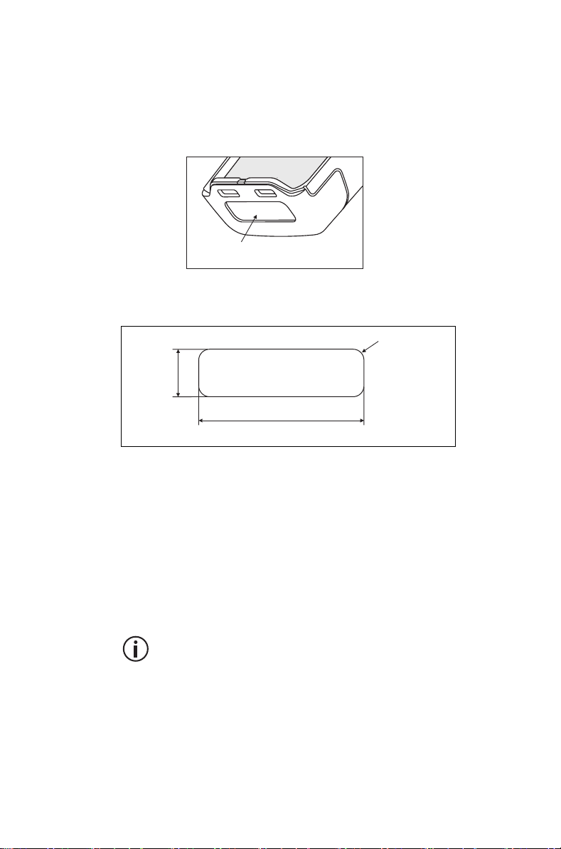
Attaching a label to the front panel
If a customer requires an additional label, attach the
label in the spare label recess in the bottom edge of
the radio front panel. In this position, the label is still
visible while the battery is attached to the radio.
spare label recess
The diagram below shows the specified dimensions of
the label.
0.28 in
(7 mm)
1.22 in (31 mm)
maximum label thickness: 0.03 in (0.8 mm)
R0.02 in
(0.5 mm)
Charging the battery before first
use
Before using your battery for the first time, you must
charge it. Follow the instructions included with your
Tait charger. This information is repeated in the
section "Charging and caring for batteries" on
page 144.
For best charging performance, switch off the
radio before placing it in the charger.
Before using your radio 35
Page 36
Attaching the battery
Warning Use only a Tait-supplied, IS and
NI-approved battery with an IS and NI radio.
Notice Fit the bottom edge of the battery to the radio,
then the top edge. Attempting to fit the top edge first
may damage the contacts.
1 Rotate the power/volume control switch
counterclockwise to turn off the radio.
If the battery has been attached while the radio
is turned on, turn the radio off and then on again
before use.
2 Holding the radio firmly, align the back of the
battery with the back of the chassis.
3 Place the two lugs at the bottom edge of the
battery into the two slots in the bottom of the front
panel.
4 Lightly press the top of the battery towards the
radio until the battery catch clicks.
5 Make sure that the battery is firmly in position.
Removing the battery
The battery is secured to the radio by a battery catch
in the radio’s rear panel.
To remove the battery from the radio, so that the
battery can be charged or replaced:
1 Rotate the power/volume control switch
counterclockwise to turn off the radio.
2 Slide the battery catch up.
3 From the sides, pull the battery away from the
radio.
36 Before using your radio
If the battery has been removed while the radio
is turned on, turn the radio off and then on again
before use.
Page 37

Attaching the antenna
Before using the radio, screw the antenna clockwise
into the antenna connector. The antenna should be
screwed sufficiently tight so that it doesn’t unscrew
easily. This is important as it creates a seal.
Removing the antenna
Warning Do not change the antenna in a hazardous
location. An explosion could cause serious injury or
death.
Use a firm grip and turn the antenna counterclockwise
half a turn. Use a lighter grip to fully unscrew the
antenna, and carefully remove it.
Attaching a belt clip
To attach a belt clip to the radio:
1 Slide the belt clip into the two grooves at the top of
the battery.
2 Press down on the belt clip until it snaps into place.
Removing a belt clip
The belt clip has been designed to prevent accidental
removal, but you can take it off, if required.
To remove a belt clip from a battery:
1 Insert a flat screwdriver blade or similar flat object
under the lip of the release lock (that is, between it
and the metal slider).
2 Lift the release lock up (away from the metal slider)
and hold it in position.
3 Slide the belt clip out.
Before using your radio 37
Page 38

Installing an audio accessory
Warning Use only Tait-supplied, IS and NI-approved
audio accessories with IS and NI radios. Fitting an
audio accessory that is not IS-approved exposes the
customer to a risk of explosion which could cause
serious injury or death. For an up-to-date list of
approved audio accessories, contact your regional
Tait office. For detailed information about IS and NI
radios and how to identify them, see "Intrinsically Safe
and Non-Incendive radios and accessories" on
page 8.
Audio accessories plug into the radio’s accessory
connector. The accessory connector is protected by a
cover, which needs to be removed before an
accessory can be installed.
Notice The accessory cover protects the accessory
connector from electrostatic discharge. Keep the
cover in place unless the connector is in use.
To remove the accessory cover and install an audio
accessory:
1 Use a coin or other blunt object to loosen the screw
that secures the accessory cover to the radio.
2 Remove the accessory cover and store it in a safe
place.
3 Plug the accessory into the accessory connector.
4 Tighten the screw.
38 Before using your radio
Page 39

3 Getting started
This section gives an overview of your DMR radio,
describes the radio’s controls and indicators, and
explains how the radio menus are organized.
This section covers:
■ About your DMR digital radio
■ About the radio controls
■ Understanding the radio display
■ Understanding the radio indicators
■ Using function keys to access frequently used fea-
tures
■ Navigating the radio’s menus
■ Using the alphanumeric keys to search a list
Getting started 39
Page 40

About your DMR digital radio
Your DMR digital radio can be programmed for DMR
conventional or DMR trunked operation. Analog
conventional and MPT operation is also available.
DMR and MPT trunking operation is controlled
by a software license (SFE) and may not be
available with your radio.
In DMR and MPT trunking operation, dual-mode
networks are able to receive both digital and analog
calls.
You may notice differences between digital and
analog calls in terms of:
■ static noise in low signal areas, and
■ radio coverage in marginal reception areas.
Lack of static noise
On digital networks there is no static noise, even in
low signal areas. This lack of static is because your
digital radio removes the ‘noise’ from the call, so that
you hear only clear voice.
Coverage
40 Getting started
With digital networks, a call remains clear and then
drops off quickly at the border of a coverage area. The
reason for this is that a digital call is either received or
it isn't. With analog networks, the background noise in
a call gets progressively worse when you are in fringe
areas or even slightly outside normal coverage areas.
Page 41

What you hear on an analog channel
On analog channels, your radio may be programmed
so that you hear all conversations on a channel, or
your user group may be segregated from other user
groups by using special signaling. The special
signaling is used to control the muting and unmuting
of your radio, so that your radio is muted when other
user groups are talking and unmuted for members of
your user group.
There are two muting controls that operate in your
radio:
■ signaling mute
■ squelch
Signaling mute
The radio’s signaling mute only allows the radio to
unmute if the incoming call carries the tones specific
to your user group. Your user group may use tones
that are either audible, subaudible or both.
Squelch
The radio’s squelch allows the radio to unmute only
when the strength of the incoming signal is above a
predetermined threshold. This means that only
signals of reasonable intelligibility are made audible.
Getting started 41
Page 42
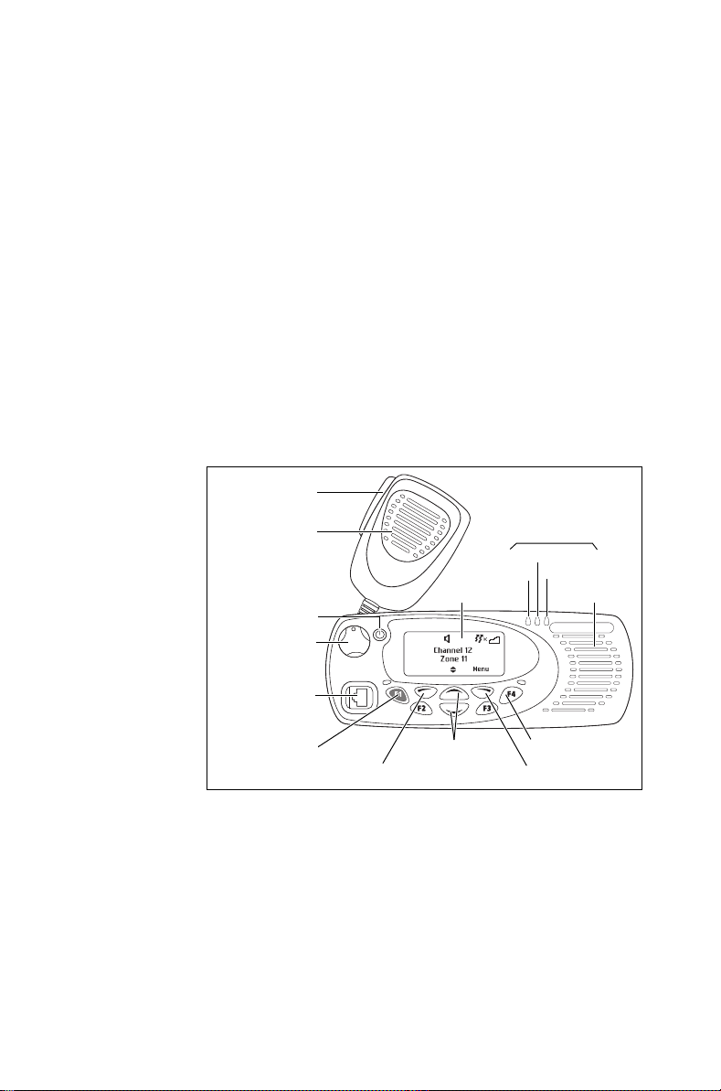
About the radio controls
The radio controls are the PTT key, volume control,
on / off key, scroll keys, selection keys and function
keys. Some keys have functions assigned to both
short and long key presses:
The radio controls are the PTT key, power/volume
control, channel selector, 3-way selector control
(optional), scroll keys, selection keys, and function
keys. Some keys have functions assigned to both
short and long key presses:
■ a short key press is less than one second, and
■ a long key press is more than one second.
The radio controls and their functions are described in
the following sections.
PTT key
(press-to-talk)
microphone
display
on/off key
volume
control
radio status
LEDs
green
red
orange
speaker
42 Getting started
microphone
socket
emergency
key
scroll
left selection key right selection key
keys
function keys
1 to 4
Page 43
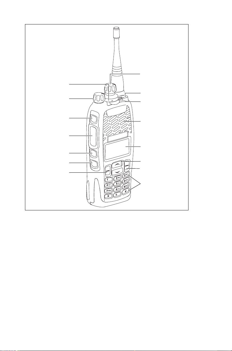
3-way selector
control (optional)
power / volume
control
channel selector
function key 1
status LED
function key 2
PTT key
(press-to-talk)
function key 3
function key 4
left selection key
speaker /
microphone
display
scroll keys
right selection key
alphanumeric
keys
Getting started 43
Page 44

Name Function
PTT key Press and hold to transmit and release to
listen
Volume control Rotate to change the speaker volume
On/off key Turn the radio on or off with a long press
Power/volume
control
Channel
Rotate to turn the radio on and change
the speaker volume
Select and change channels
selector
3-way selector
Select frequently used features
(optional)
Left and right
selection keys
Action determined by the text above the
selection key
Scroll keys Scroll up and down through a list of menu
options, scroll left and right in messages,
or select the Quick Access menu
Emergency key Activates emergency mode
Function keys Programmed for frequently used options
Alphanumeric
Used to enter letters and numbers
keys
44 Getting started
Page 45
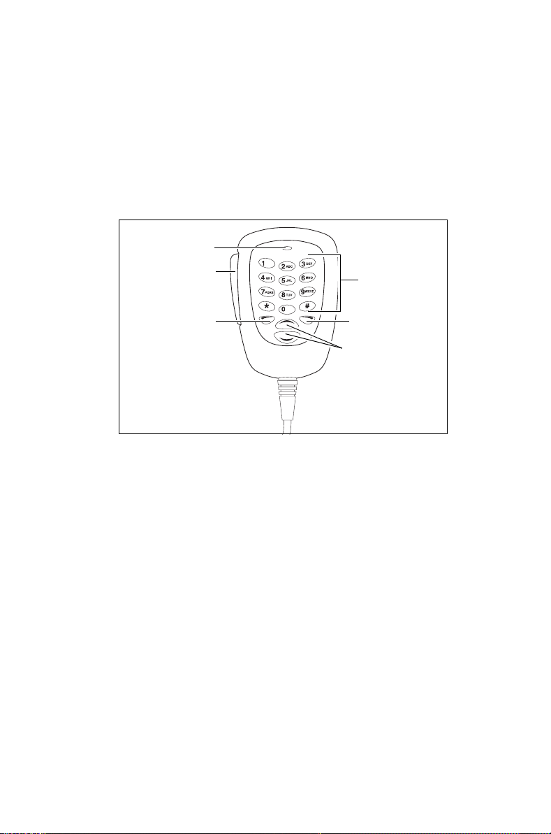
About the keypad microphone
Your radio may have a keypad microphone installed.
The keypad microphone has a PTT key as well as
alphanumeric keys, two scroll keys, and left and right
selection keys.
The PTT key, the scroll keys and the selection keys all
work in the same way as those on the radio control
head (see "About the radio controls").
microphone
PTT key
(press-to-talk)
left selection
key
alphanumeric
keys
right selection
key
scroll keys
Getting started 45
Page 46
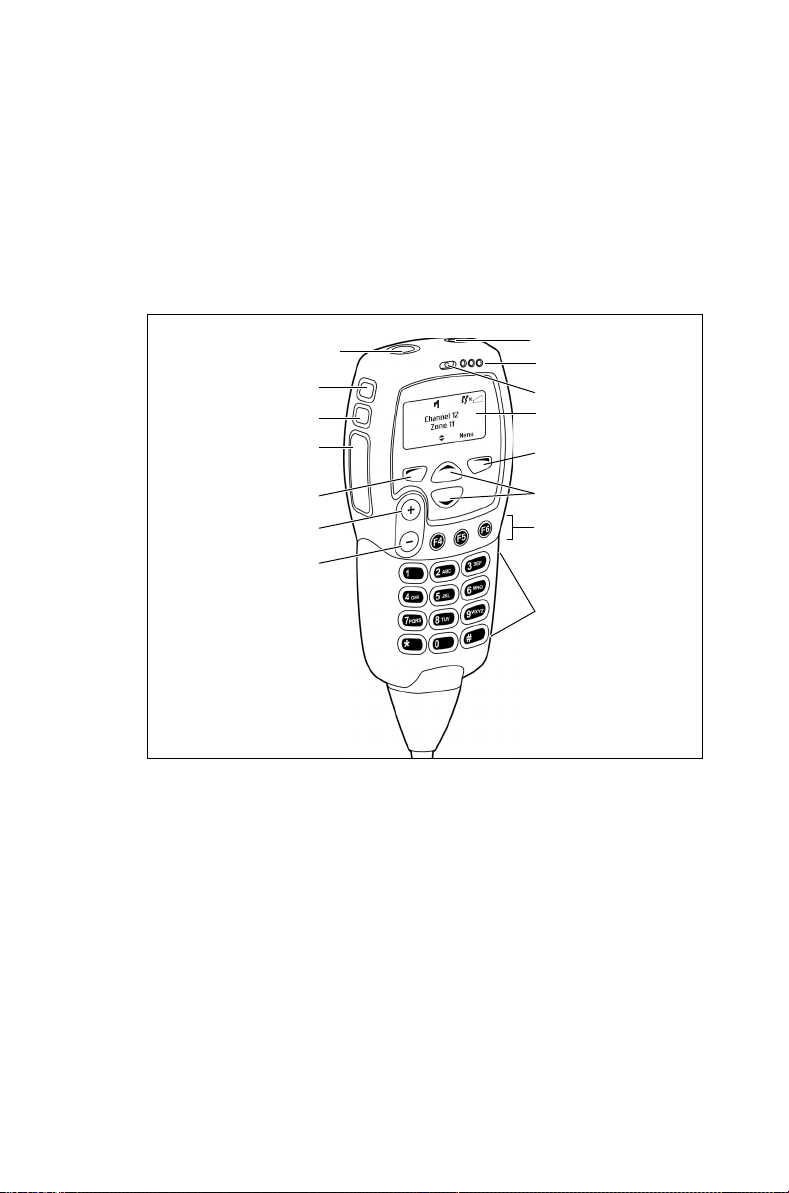
About the hand-held control head
Your radio may have a hand-held control head installed,
to enable you to operate the radio at a distance from the
radio body.
The keys and controls work in the same way as those
on the standard control head, with the exception of the
PTT and volume up and down keys. The hand-held
control head also has two additional function keys.
function key 1
function key 2
function key 3
PTT key
(press-to-talk)
left selection key
volume up
volume down
on/off key
status LEDs
microphone
display
right selection
key
scroll keys
function keys 4
to 6
alphanumeric
keys
46 Getting started
Page 47
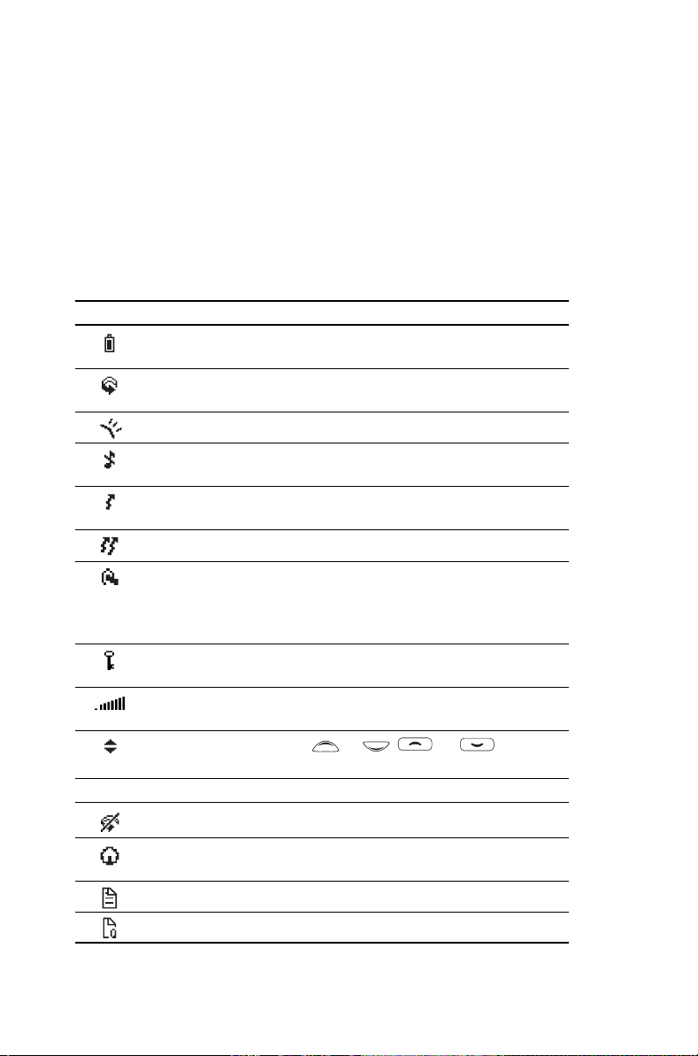
Understanding the radio display
The messages and icons you see on your radio
display depend on the mode in which your radio is
operating and the way it is programmed.
Radio display icons
These are some of the icons you may see on your
radio display:
Icon Meaning
Battery indicator: shows how much charge is available in
the battery
Scanning: your radio is monitoring a group of channels or
workgroups for activity
External alert: external alert is turned on
Silent operation: your radio’s audible tones have been
turned off
Low-power transmit: your radio is set to transmit on low
power
Transmit: your radio is transmitting
Headset connected: there is a wireless headset connected
to your radio
Flashing: your radio is attempting to connect to a headset,
or the headset connection has been lost
Scrambler: the voice-inversion scrambler is turned on
(analog channels only)
Signal strength indicator: the more bars, the stronger the
signal being received by the radio
Scrolling: you can use or or
through a list, or access a Quick Reference menu
Trunked mode icons
Scanning: scanning has been turned off
to move
Homegroup: your radio has been returned to the
homegroup using the homegroup toggle function key
Call queuing: call queuing is turned on
Call queuing: there are calls in the call queue
Getting started 47
Page 48
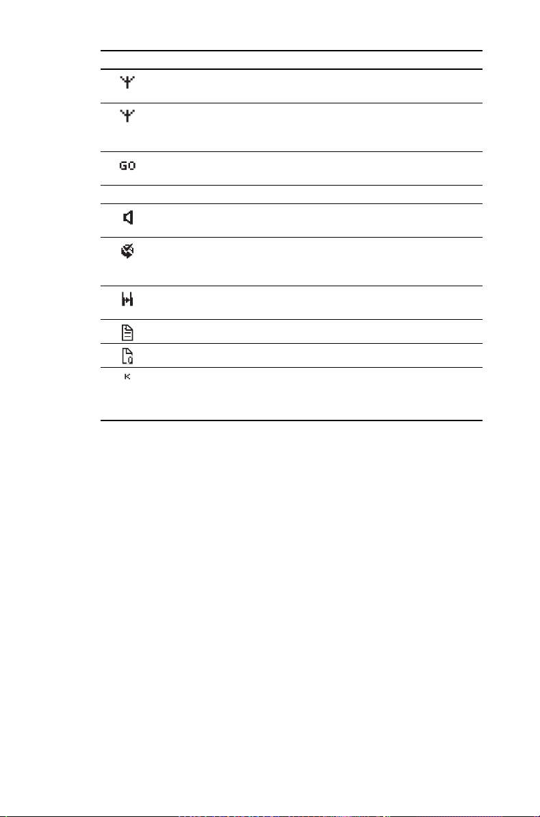
Icon Meaning
Network (flashing): your radio is registered on a DMR or
MPT trunked network
Network: your radio is registered on a trunked network
Flashing: your radio is attempting to register on a trunked
network
Trunking: your radio has established a call and you are now
able to speak to the other party
Conventional mode icons
Monitor or squelch override: monitor or squelch override is
turned on
Scanning: your radio is monitoring a group of channels for
activity, and the currently selected channel is a member of
the scan group.
Repeater talkaround: your radio is operating in repeater
talkaround mode, or you are on a simplex channel
Text message: there is no text message in the call queue
Text message: there is a text message in the call queue
Zone: this letter represents the zone in which your radio is
operating, where
represents zone 11)
A is zone 1, Z is zone 26 (for example, K
48 Getting started
Page 49
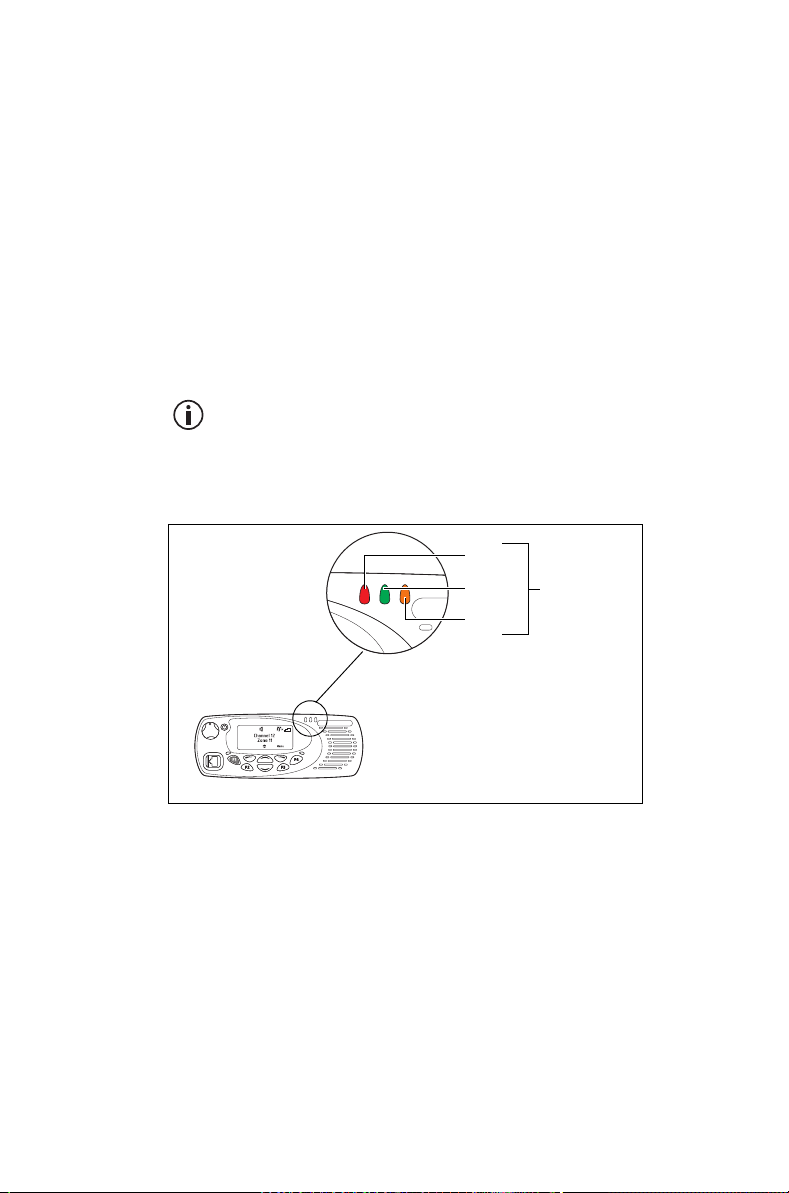
Understanding the radio
indicators
The status LED indicators and the radio’s audible
tones—together with the radio display—all combine to
give you information about the state of your radio.
The status LED indicator and the radio’s audible
tones—together with the radio display—all combine to
give you information about the state of your radio.
The most common way the indicators work is
described in the following sections.
The way these indicators behave may be
affected by the way your radio is programmed.
Status indicators
red
green
orange
status
LEDs
Getting started 49
Page 50
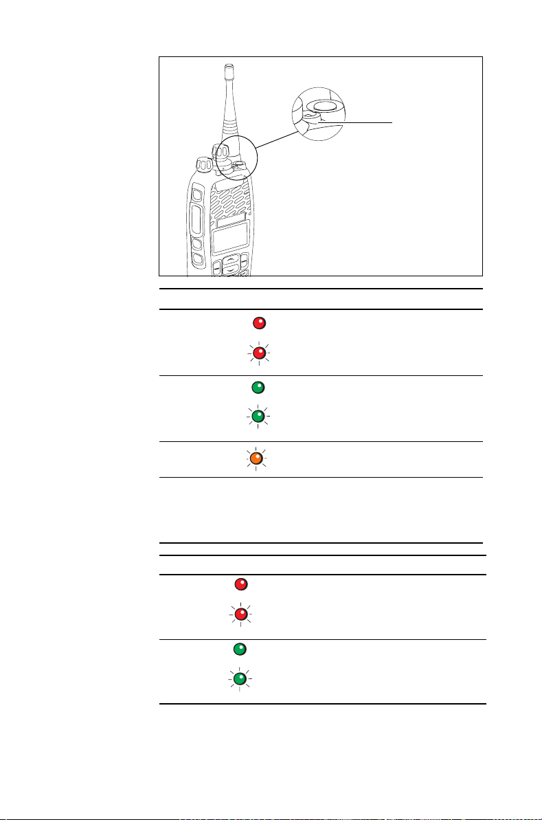
status LED
Color Meaning
Red
(transmit)
Glowing: your radio is transmitting
Flashing: your transmit timer is
about to expire
Green
(receive)
Glowing: the current channel is
busy
Flashing: you have received a call
(analog channel only)
Orange
(network)
Flashing: you are registered on a
trunked network
All LEDs off Trunked: network not available, or
your radio is attempting to register
on a trunked network
Conventional: receive standby
50 Getting started
Color Meaning
Red
(transmit)
On: your radio is transmitting
Flashing: your transmit timer is about to
expire
Green
On: the current channel is busy
(receive)
Flashing: you have received a call or
monitor is active
Page 51
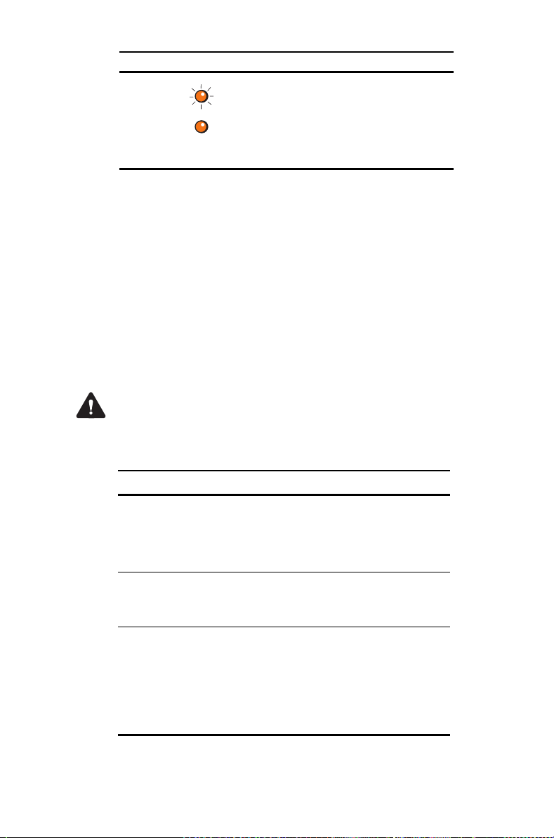
Color Meaning
Orange
(network)
Audible tones
The radio uses audible tones to alert you to its status:
■ Radio controls and keypress tones—the tones
and beeps you hear when you press your radio’s
keys or use the controls.
■ Incoming call tone—when the radio is receiving
a call.
■ Warning tones—when there is an error, or the bat-
tery is low, for example.
Warning If quiet or silent mode is turned on, you will
not hear any alert tones.
Some of the more common audible tones are
described below:
Off: No service
Flashing: Limited service (no inter-site or
fixed network services are available)
On: Full service
For more information see "Checking that
your network is available" on page 97.
Tone Meaning
One short
beep
One short,
low-pitched
beep
One long, lowpitched beep
■ Valid keypress: The action you have
attempted is permitted.
■ Function activated: A function has
been turned on (using a function key).
Function deactivated: A function has been
turned off (using a function key).
■ Invalid keypress: The action you have
attempted is not permitted.
■ Transmission inhibited: You have
attempted to transmit, but for some
reason you cannot make a call at
this time.
Getting started 51
Page 52

Ton e Mea ning
Two short
beeps
■ Radio turned on: The radio is powered
on and ready to use.
■ Radio is revived: The radio has been
made operable by your service provider.
Three short
beeps
Channel now free: You were prevented
from transmitting on a busy channel and
that channel is now free.
Three long
beeps
Transmit timeout imminent: Your transmit
timer will expire and your current
transmission will be terminated.
one short,
high-pitched
Radio is stunned: The radio has been
made inoperable by your service provider.
beep
two lowpitched beeps
Radio’s temperature is high: The radio’s
temperature is in the high-temperature
range, but the radio will continue
to operate.
52 Getting started
two highpitched beeps
Continuous
low-pitched
tone
two long highlow pitched
tone pairs
Radio’s temperature is very high: The
radio’s temperature is in the very high
temperature range and all transmissions
will now be at low power; if the radio’s
temperature rises outside this range,
transmissions will be inhibited. Turn off
the radio and allow it to cool down.
Radio system error: A system error has
occurred and the radio may be inoperable.
Contact your radio provider.
Synthesizer is out-of-lock: The radio’s
synthesizer is out-of-lock on the current
channel and you cannot operate on that
channel (Out of lock appears on the
display).
Page 53
Voice annunciation
In conventional mode, your radio may be programmed
to play a pre-recorded message for the start-up
channel and, when changing a channel, and for the
battery condition.
Using function keys to access
frequently used features
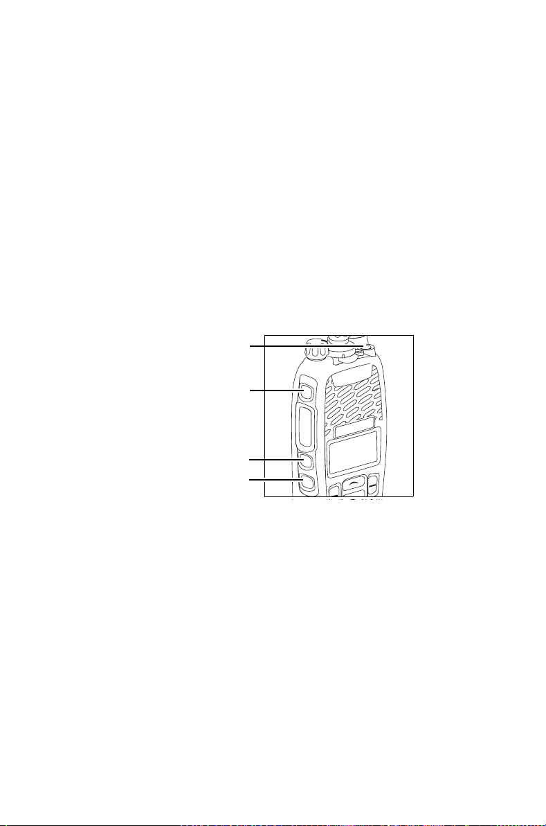
The function keys provide access to some of the
features you will use most often. These features are
assigned to the function keys when the radio is
programmed. Some keys may have a feature
associated with both a short key press and a long key
press.
function key 1
(emergency key)
function key 2
function key 3
function key 4
The function keys provide access to some of the
features you use most often. These features are
assigned to the function keys when the radio is
programmed. Some keys may have a feature
associated with both a short key press and a long key
press.
Getting started 53
Page 54
Channel 12
Zone 11
Talkgr
Menu
Viewing the function key settings
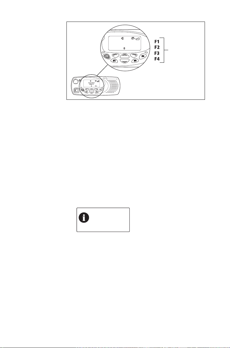
Use the Main menu to check the features assigned to
your radio’s function keys:
1 Press Menu and select Radio settings > Radio
info > Key settings.
2 In the Key Settings menu, scroll through the list of
function keys.
3 Press Select to view details of the function
associated with a particular function key.
The example shown is for a function key
programmed to turn backlighting on and off.
function keys
54 Getting started
Backlighting
toggle
OKBack
4 Press Back to return to the Key Settings menu.
Page 55
Use the following table to record the function keys
programmed for your radio:
Short key press Long key press
F1
F2
F3
F4
1
F5
1
F6
1. On speaker microphone (if fitted)
For more information about the function keys that can
be programmed on your radio, contact your radio
provider.
Navigating the radio’s menus
Your radio has a number of menus, each containing
lists or submenus. The menus available depend on
the way your radio is programmed.
Using the Main menu
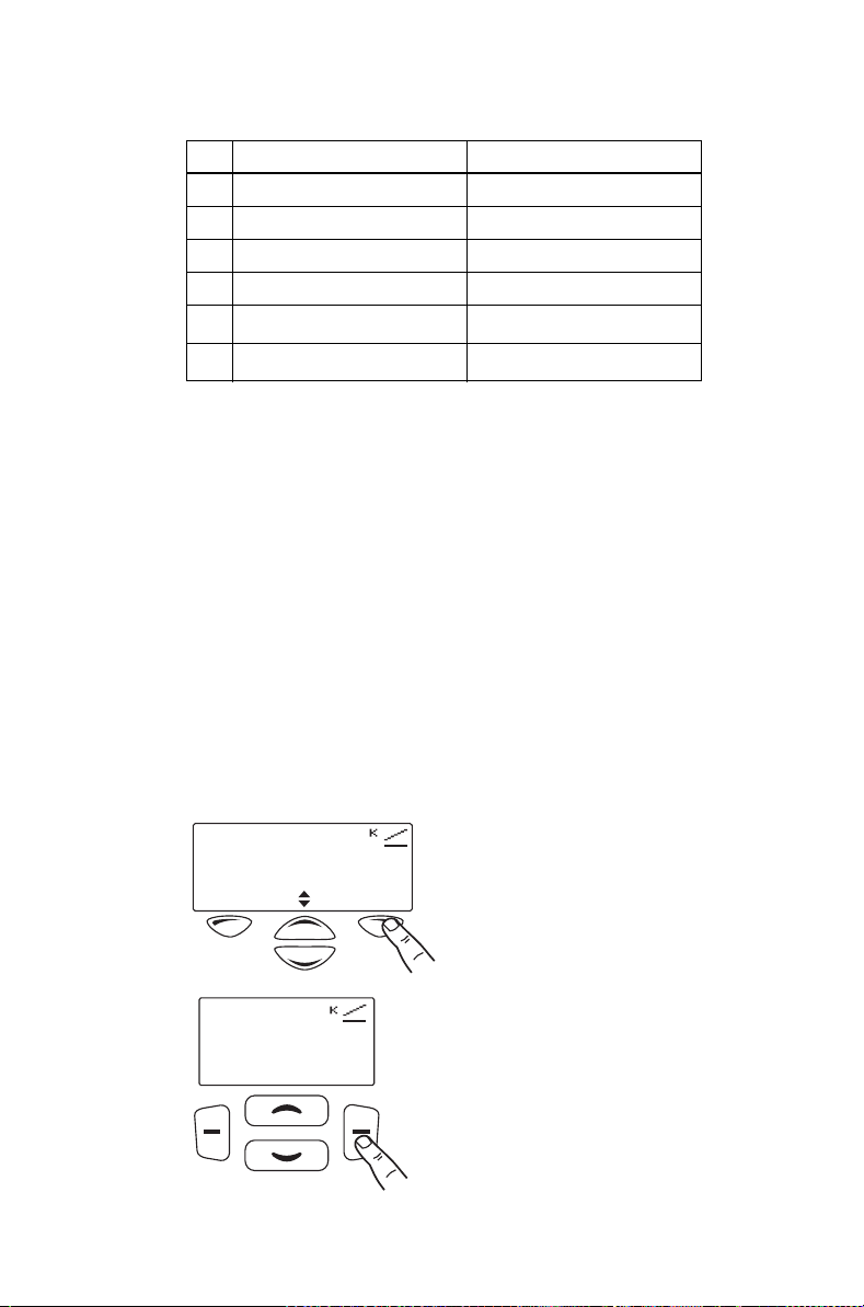
To access the Main menu, press the right selection
key whenever Menu appears above it.
Channel 12
Zone 11
Channel 12
Zone 11
Lock Menu
Menu
Getting started 55
Page 56
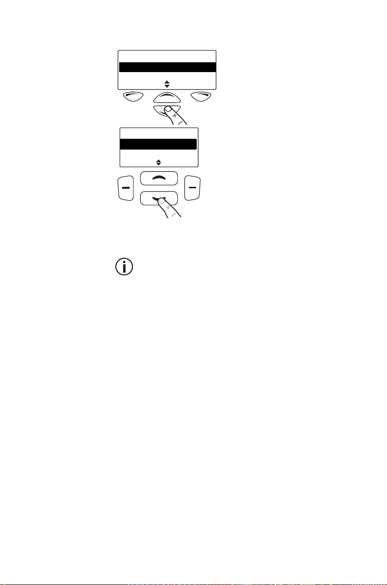
Use the scroll keys to move through the menu list.
Main menu
Zones
Address book
SelectBack
Main menu
Zones
Address book
Back Select
When the menu you want is highlighted, press Select
to open the menu you have chosen.
To quickly exit the menu system, press and hold
the left selection key when the word Cancel or
Back appears above it.
Accessing frequently used menus
56 Getting started
Depending on how your radio is programmed, you
may have two different Quick Access menus. One
Quick Access menu is displayed when you press a
scroll key, and the other when you press the left
selection key. These give you easy access to the
menus you use most often.
Using the scroll key Quick Access menu
There are two ways to use this Quick Access menu:
■ Use the scroll keys to scroll through a list of zones
or channels.
■ Press the scroll keys and the Quick Access menu
appears.
Page 57
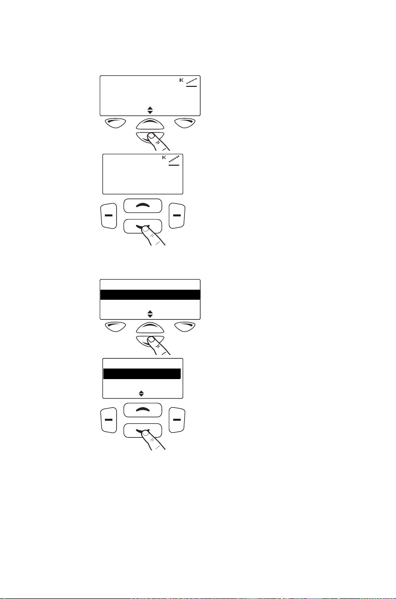
In this example, the Channels menu is the Quick
Access menu. Use the scroll keys to go directly to
the Channels menu.
Channel 12
Zone 11
Menu
Channel 12
Zone 11
Menu
The Channels menu, with a list of your available
channels, is now displayed.
Channels
Channel 1
Channel 2
SelectBack
Channels
Channel 1
Channel 2
Back Select
Using the left selection key Quick
Access menu
The text above the left selection key corresponds to
the Quick Access menu, for example, Zones.
To use this Quick Access menu:
Getting started 57
Page 58
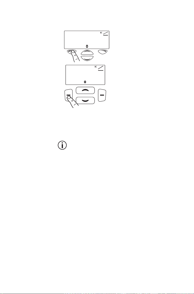
■
Press the left selection key and the associated
menu appears.
Channel 12
Zone 11
MenuZones
Channel 12
Zone 11
Zones Menu
Using the alphanumeric keys to
search a list
This feature is only available for radios with
alphanumeric keys.
If a blinking cursor appears when you select a list, you
are able to search for the menu item you want using
the alphanumeric keys. This is of particular benefit if
you have a large number of items in a list.
58 Getting started
Lists that you may be able to search are channels,
zones, workgroups, and preset calls.
■ To search a list, enter the required name using the
keypad.
Page 59

4 Basic operation
This section describes the basic operation of your
radio.
This section covers:
■ Turning the radio on and off
■ Adjusting the speaker volume
■ Locking and unlocking the keypad
■ Using a wireless headset
■ Changing the radio’s operating mode
■ Setting and viewing the radio’s time and date
Basic operation 59
Page 60
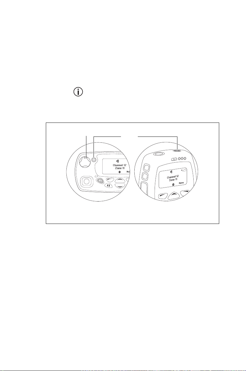
Turning the radio on and off
Rotate the power/volume control switch clockwise to
turn the radio on. Rotate the switch counterclockwise
to turn the radio off.
When the radio is first turned on, the status LED briefly
glows red, and the radio gives two short beeps.
Your radio may not turn on if your battery is very
low. (See "Low battery warning" on page 149.)
Long press the on/off key to turn the radio either on
or off.
volume control
Standard control head Hand-held control head
When the radio is first turned on, the red, green, and
orange LEDs flash briefly, and the radio gives two
short beeps. A brief message may appear on the
display.
on/off
Security lock on power-up feature
Your radio may be automatically locked each time it is
powered-up. If the message Enter PIN appears on
the display, enter your assigned PIN (personal
identification number). See “Unlocking the radio”
below.
60 Basic operation
Page 61

Locking the radio
1 Press Menu and select Radio settings >
Functions > Lock radio. (Depending on how your
radio is programmed, you may be able to press a
function key to turn radio lock on and off.)
2 Scroll to either On or Off and press Select.
(The current setting is highlighted.)
The radio is now locked, and the message Enter
PIN appears on the display.
The radio remains locked until the correct
sequence of keys is pressed. If you forget the
unlock sequence or you do not know it, contact
your radio provider for assistance.
Unlocking the radio
■ To unlock your radio, use the unlock sequence
you have been given. (This is a pre-programmed
sequence of four keys.)
Adjusting the speaker volume
Standard control head
Rotate the volume control clockwise to increase the
speaker volume and counterclockwise to decrease
the volume. The raised dot indicates the current
volume setting.
Hand-held control head
Press to increase the speaker volume, and to
decrease the volume.
Rotate the power/volume control clockwise to
increase the speaker volume and counterclockwise to
decrease the volume.
The volume control also changes the volume
level of the radio’s audible indicators.
Basic operation 61
Page 62

Locking and unlocking the
keypad
The keypad lock feature prevents you from pressing a
key accidentally. The number of keys that are locked
depends on the way your radio is programmed.
If you receive a call while the keypad is locked, press
any key to answer.
To lock the keypad:
■ Press and hold the right selection key for about
one second.
(Depending on your radio model and the way it is
programmed, your radio may have a 3-way
selector that can be used to lock the keypad.)
The message Keypad locked briefly appears on
the display, and Unlock appears above the right
selection key, in place of Menu.
When any of the locked keys are pressed, the
message Keypad lock active appears.
To unlock the keypad:
Using a wireless headset
62 Basic operation
■ Press and hold the right selection key for about
one second.
This feature is controlled by a software license
(SFE) and may not be available with your radio.
You may be able to connect a Bluetooth® wireless
headset to your radio, using the Wireless headset
menu or a function key.
When you have selected a menu option in the
Wireless headset menu, you can still receive
and reply to calls without interrupting the
selected operation.
Page 63

Headset compatibility with Tait radios
Bluetooth wireless headsets may operate with Tait
radios, provided the headset:
■ Is compatible with the Bluetooth Specification Ver-
sion 2.0 or higher. Tait recommends Bluetooth
Specification Version 2.1 or higher.
■ Includes Bluetooth Headset Profile (HSP) adopted
version 1.1 or 1.2, or Bluetooth Handsfree Profile
(HFP) version 1.5 or 1.6.
Wearing the headset
Place the headset on your ear. Depending on which
ear you are going to wear the headset, simply adjust
the ear hook accordingly.
To get the best performance from your headset:
1 Do not block the device’s internal antenna (see the
device’s user documentation). The human body
can interfere with a Bluetooth signal.
2 If you usually use your radio with your right hand,
wear the headset on your right ear.
3 Avoid coming in contact with the internal antenna
of a headset or radio.
Pairing a wireless headset with the radio
Before attempting to connect a wireless
headset, Tait recommends that the headset is
fully charged. Refer to the headset installation
instructions for charging instructions.
Pairing creates a unique and encrypted wireless link
between the Bluetooth-capable radio, and the
Bluetooth headset. To use a headset with your radio,
the devices must first be paired.
Basic operation 63
Page 64
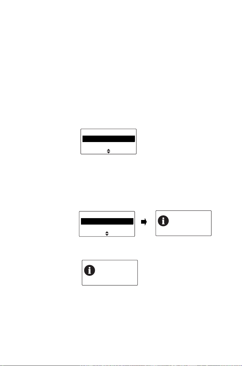
When you connect to a wireless headset for the first
time, you need to instruct the radio to search for
compatible headsets using Bluetooth wireless
technology. The search should take less than one
minute.
To pair a wireless headset with the radio:
1 Turn on the radio.
2 Put the wireless headset into pairing mode.
Refer to the headset installation instructions for
instructions on how to do this.
3 Press Menu and select Wireless headset > Find
new devices.
Wireless headset
Find new devices
Options
SelectBack
The New devices menu opens, and while the
radio searches for the new device, the message
Searching ... appears.
4 Select Connect when the required headset
appears in the list of new devices, then Yes to add
the headset to My Headsets.
64 Basic operation
New devices
HM1100
Searching ,,,
ConnectCancel
The message Connecting appears, while the
radio attempts to pair with the headset.
Add to My
Headsets?
No
Connecting:
HM1100
Clear
Yes
Page 65
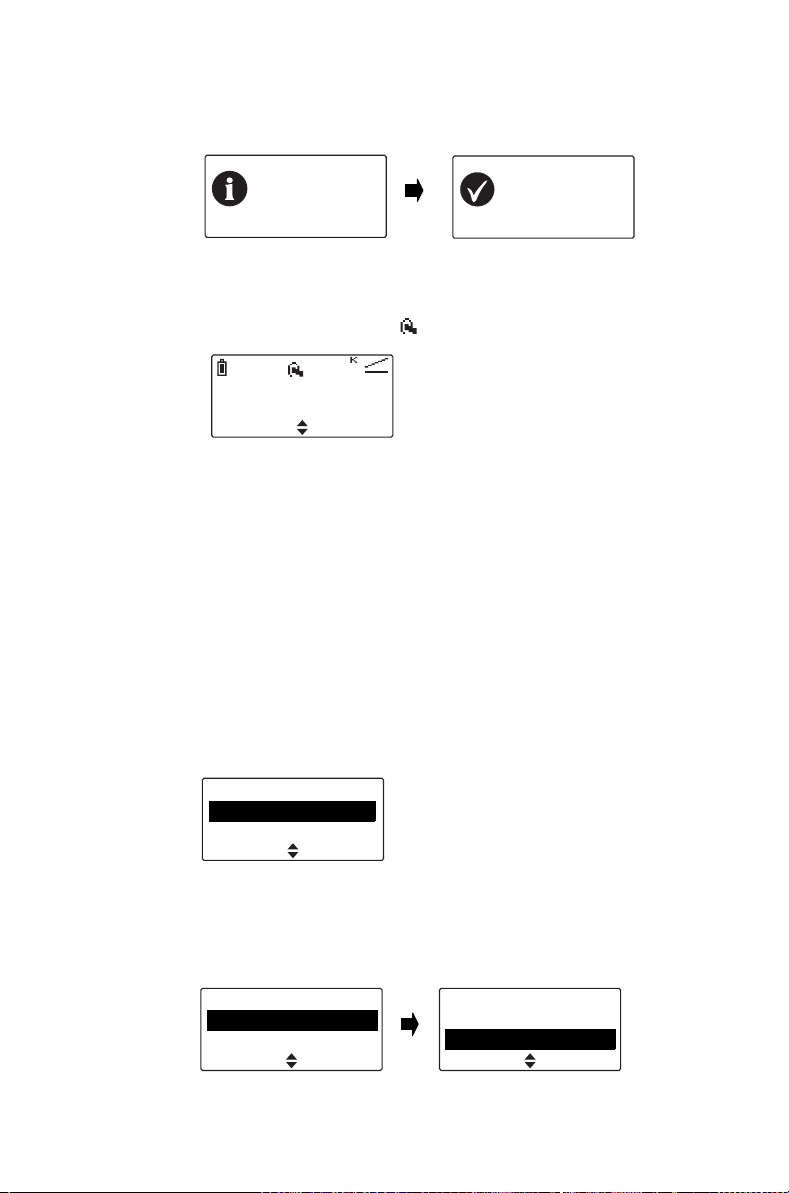
5 When the message Calling. Answer on headset
appears, press the Answer button on the headset
to confirm the connection.
Calling.
Answer on
headset
Clear
6 Repeat the previous steps to add other headsets.
While the wireless headset is connected, the
wireless headset icon appears on the display.
Cancel
Channel 12
Menu
Managing your headsets
Once a headset has been added to My Headsets, the
Manage headsets menu item appears under the
Wireless headsets menu. The Manage headsets
menu shows the headsets currently in My Headsets,
along with the following information:
■ + This headset is currently connected.
■ a This headset will be automatically connected.
■ c The radio will ask you for confirmation before
connecting this headset.
Headset
connected
Clear
My Headsets
BlueAnt T1V1. +a
CSR-bc6 a
Back
Press Options to disconnect or connect a headset
(Disconnect, Connect), change the priority order of
the headsets (Move down), or remove a headset
from My Headsets (Remove, Remove all).
My headsets
Disconnect
Move down
Options
SelectBack
My headsets
Disconnect
Move down
SelectBack
Basic operation 65
Page 66
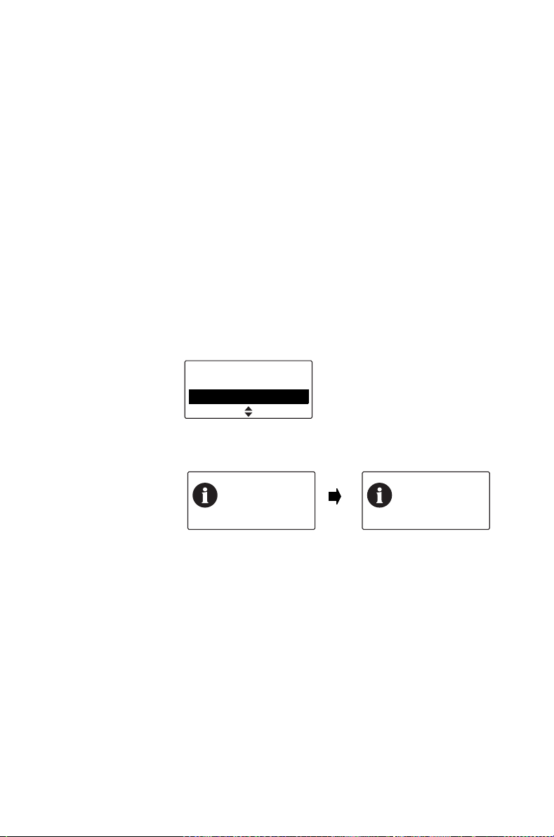
Disconnecting the headset
To disconnect the headset from your radio:
■ Press Menu and select Wireless headset >
Disconnect.
Alternatively, in the My headsets menu select
Options > Disconnect.
Reconnecting the headset
Your radio may be programmed so that each time the
headset is turned on, it will automatically reconnect to
the radio.
If the radio does not automatically reconnect to the
headset:
1 On the radio, press Menu and select Wireless
headset > Reconnect last.
Wireless headset
Connect
Reconnect last
SelectBack
The radio then prompts you to connect to the
headsets in My Headsets, in priority order.
66 Basic operation
Connect.
HM1100?
No
Yes
Connect
BlueAnt T1
V1?
No
Yes
2 Select Yes to connect, or No to choose another
headset.
Changing the way your headset reconnects
You can use the Power-on option menu to change
the way your radio reconnects with a headset when
the radio is first turned on. The choices are:
■ None: The radio does not connect to any head-
sets, and you will need to manually connect or
reconnect to your headset.
■ Reconnect last: The radio connects to the previ-
ously connected headset.
Page 67
■
Connect: The radio will attempt to connect to the
headsets in My Headsets, in priority order.
To change the power-on option:
1 Press Menu and select Wireless headset >
Options > Power-on option, and change to the
required option.
Power-on option
None
Reconnect last
SelectBack
Basic operation 67
Page 68
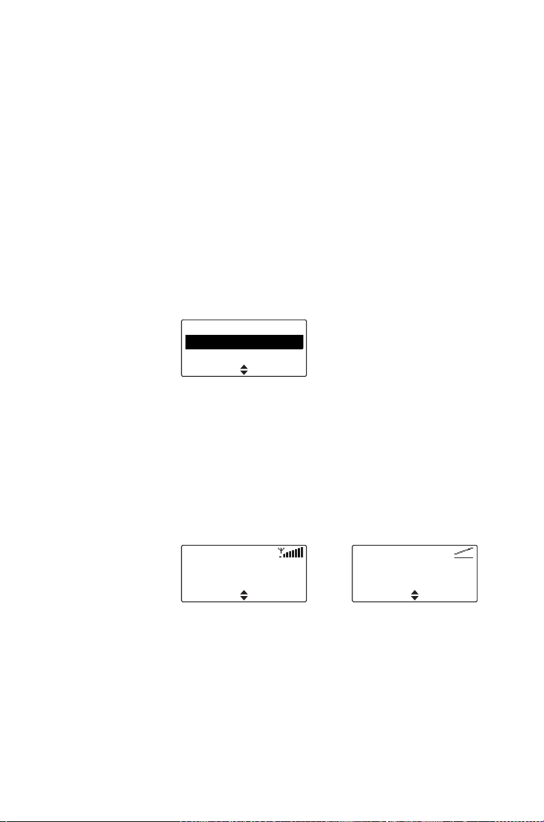
Changing the radio’s operating
mode
The way your radio performs basic functions, such as
sending and receiving calls, depends on the operating
mode of your network. The two operating modes that
may be available on your radio are:
■ conventional mode (see "Operating in conven-
tional mode" on page 70), and
■ trunked mode (see "Operating in trunked mode"
on page 97).
To change your operating mode:
1 Press Menu and select Change mode.
Main menu
Change mode
Channels
(Depending on how your radio is programmed, you
may be able to press a function key to change
mode.)
2 Select Yes to confirm your selection, and your
radio now shows the default display for either
trunked or conventional.
SelectBack
68 Basic operation
The following examples show typical default
displays for trunked and conventional modes.
Network 1
200-20001-20
trunked mode conventional mode
16A
Channel 1
Zone 2
Menu
Menu
Page 69

Setting and viewing the radio’s
time and date
Your radio may be programmed to use its internal
real-time clock. You may be able to view the time and
date via a function key or via the radio menu. Other
features may also make use of the radio’s time and
date by showing entries based on the current clock
setting.
To set the time, date, and time format:
Your radio may be programmed to allow you to
set time and date manually, or time and date can
be updated using a GPS source.
1 Press Menu and select Time and Date and the
corresponding option.
2 Follow the prompts on the display.
To view the time and date:
■ Press Menu and select Time and Date > View
clock (Depending on how your radio is pro-
grammed, you may be able to press a function
key to view the time and date).
Basic operation 69
Page 70

5Operating in
conventional mode
This section explains how to operate your radio on a
conventional network (digital and analog). This
includes how to make and receive different types of
calls, use your radio in different repeater areas, and
scan a group of channels for activity.
This section covers:
■ Selecting a zone
■ Selecting a channel
■ Selecting a group
■ Understanding talkgroups
■ Making a call
■ Making an individual call
■ Making a preset call
■ Making a call using the address book
■ Making a local call
■ Connecting to a telephone network
■ Making an emergency call
■ Sending a status message
■ Resending calls automatically
■ Transmitting at low power
■ Ending active calls
■ Using monitor and squelch override (on analog
channels)
■ Bypassing the repeater (on analog channels)
■ Receiving a call
■ Using the radio in different repeater areas
■ Scanning a group of channels
70 Operating in conventional mode
Page 71
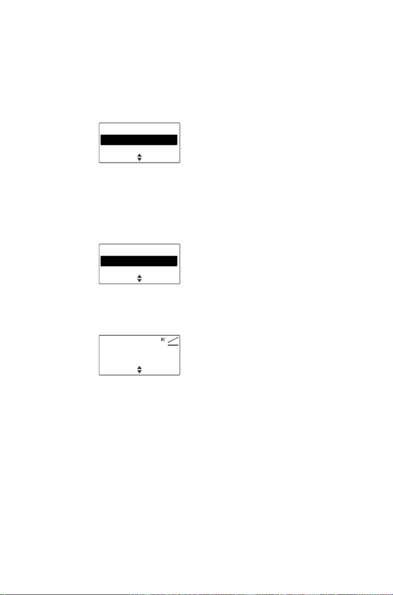
Selecting a zone
A zone is a collection of channels and groups. When
you select a zone, only the channels and groups
assigned to that zone are available.
1 Press Menu and select Zones.
Main menu
Zones
Address book
(Depending on how your radio is programmed, you
may be able to use the scroll keys or left selection
key to select the Zones menu.)
2 In the Zones menu, scroll through the list of zones
until the one you want appears.
Zones
Zone 2
Zone 3
3 Press Select, and the zone indication appears
either below the channel information, beside the
RSSI icon, or in both positions.
SelectBack
SelectBack
Channel 12
Zone 11
MenuZones
Operating in conventional mode 71
Page 72
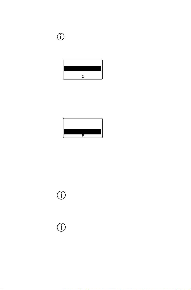
Selecting a channel
For digital channels, a talkgroup is assigned to
each channel. For more information, see
"Understanding talkgroups" on page 74.
1 Press Menu and select Channels.
Main menu
Channels
Zones
(Depending on how your radio is programmed, you
may be able to use the scroll keys or left selection
key to select the Channels menu.)
2 In the Channels menu, scroll through the list of
channels until the channel you want appears.
Channels
Channel 9
Scan 1
3 Press Select, and the programmed channel is now
shown on the display.
Using the channel selector
For channels 1 to 16, rotate the channel selector to
the channel you want. For all other channels, use the
Main menu to select a channel.
SelectBack
SelectBack
If you turn the channel selector while pressing
the PTT key, the channel will change after you
release the PTT key.
Dialing a channel
This feature is only available for radios with
alphanumeric keys.
72 Operating in conventional mode
Page 73
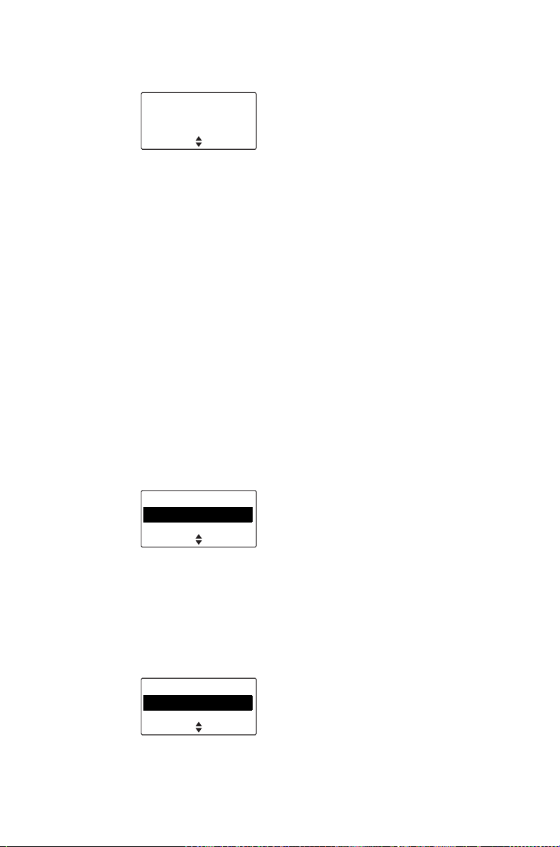
1 Dial the number associated with the channel using
the alphanumeric keys.
9
SelectClear
2 Press Select, and the programmed channel is now
shown on the display.
Selecting a group
A group is a collection of channels that are grouped
together for either scanning or voting. In the
Channels menu, the group is shown as being a single
channel item, e.g. “Scan1”.
The sections "Using the radio in different repeater
areas" on page 89 and "Scanning a group of
channels" on page 90 explain how your radio
operates once a scan group or voting group has been
selected.
Using the Main menu
1 Press Menu and select Channels.
Main menu
Channels
Zones
(Depending on how your radio is programmed, you
may be able to use a function key, the scroll keys
or left selection key to select a group.)
2 In the Channels menu, scroll through the list of
channels and groups until the group you want
appears.
SelectBack
Channels
Channel 9
Scan 1
SelectBack
Operating in conventional mode 73
Page 74
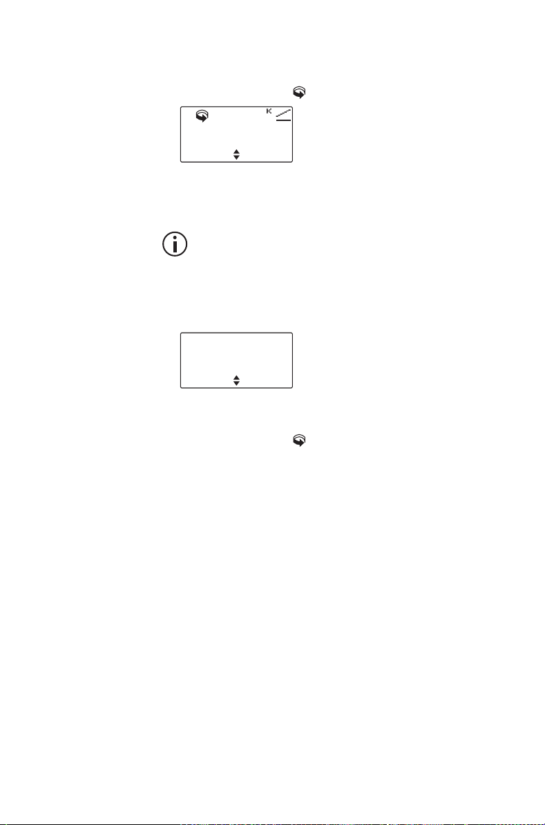
3 Press Select, and the programmed group is now
shown on the display. The orange LED glows and
the scanning icon appears on the display.
Scan 1
MenuChannels
Dialing a group
This feature is only available for radios with
alphanumeric keys.
To dial the group number from the default display:
1 Dial the number associated with the group using
the alphanumeric keys.
12
SelectClear
2 Press Select, and the programmed group is now
shown on the display. The orange LED glows and
the scanning icon appears on the display.
Understanding talkgroups
This feature is available for digital channels only.
A talkgroup is a collection of radio users with whom
you want to have private conversations. For example,
a state's public safety agencies could have the
following talkgroups:
■ Local talkgroups—used by a specific agency to
communicate within their own local agency. It may
even be made up of a county of public safety officers.
■ Regional talkgroups—used by large state agen-
cies that have regional divisions.
■ Statewide talkgroups—used by an agency to com-
municate with a public safety member in another
74 Operating in conventional mode
Page 75
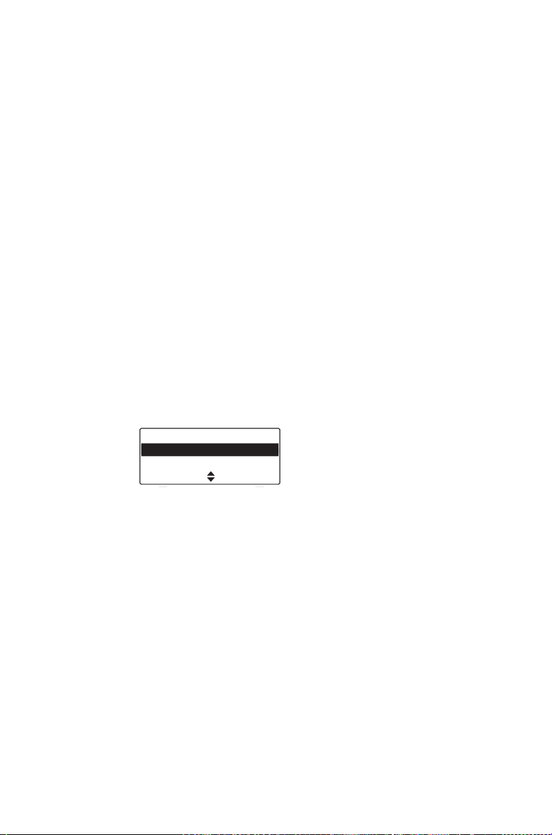
region. Statewide talkgroups, as their name suggests, enable public safety agencies to communicate with each other from one end of the state to
the other.
■ Special event talkgroups—may be used to man-
age emergencies encompassing a large area, or
even events such as visits by heads of state.
Making a talkgroup call
To make a call to the currently selected talkgroup
■ Press the PTT key.
Changing a talkgroup
1 Press Menu and select Talkgroups.
(Depending on how your radio is programmed, you
may be able to use a Quick Access menu to go to
the Talkgroup menu.)
2 Scroll through the list of talkgroups to the one you
want and press Select.
Talkgroups
Talkgroup01
Talkgroup02
SelectCancel
3 Press the PTT key to make a call to the currently
selected talkgroup.
Operating in conventional mode 75
Page 76

Making a call
The radio’s behavior when making a call changes
depending on the type of channel selected.
Channels can be programmed for:
■ DMR calls over the DMR network
■ DMR calls between radios
■ analog calls between radios
If you are on a channel programmed for calls over the
DMR network, the green LED indicates whether the
network is active. By default, the network is inactive
(green LED is off).
Initiating a call will activate the network which will
remain active for a programmed time. While the
network is active (green LED glows), you can
complete the call and start a new call.
If you are on a channel programmed for DMR or
analog calls between radios (without a radio network),
the green LED indicates activity on the channel, i.e.
whether someone is talking.
For all DMR calls (over the network or radio to radio),
you will hear a go-ahead double-beep after pressing
the PTT key (if programmed).
Receiving a new DMR call is indicated by a number
beeps (if programmed):
■ one beep: individual call
■ two beeps: group call
■ three beeps: broadcast call to all radios
DMR calls have an inactivity timeout. If a pause in the
conversation exceeds the timeout, the next press of
the PTT key will establish a new call.
76 Operating in conventional mode
Page 77

To make a call:
1 Select the required channel or scan group.
You may need to select the zone you want first,
then select the channel or group from that zone.
2 On channels programmed for DMR or analog calls
between radios (without a radio network): Check
that the channel is clear. If the green LED is
glowingLED is glowing green, the channel is busy
and you may not be able to transmit.
3 Hold the radio so that the microphone is about one
inch (2.5 cm) from your mouth and press the PTT
key to transmit.
4 Lift the microphone off the microphone clip.
5 Hold the microphone about 2 inches (5 cm) from
your mouth.
6 Press and hold the PTT key to transmit.
7 On a DMR channel: Wait for the go-ahead double-
beep (if programmed).
8 Speak clearly into the microphone and release the
PTT key when you have finished talking.
While you are transmitting, the red LED glows LED
glows red and the transmit icon appears on the
display.
You cannot change channels while
transmitting.
If you turn the channel selector while pressing
the PTT key, the channel will change after you
release the PTT key.
Limiting call time
Your radio may limit the amount of time you can talk
(transmit) continuously. This is known as the ‘transmit
timer’ or ‘time-out timer’ and allows other radio users
to make calls on that channel.
Operating in conventional mode 77
Page 78
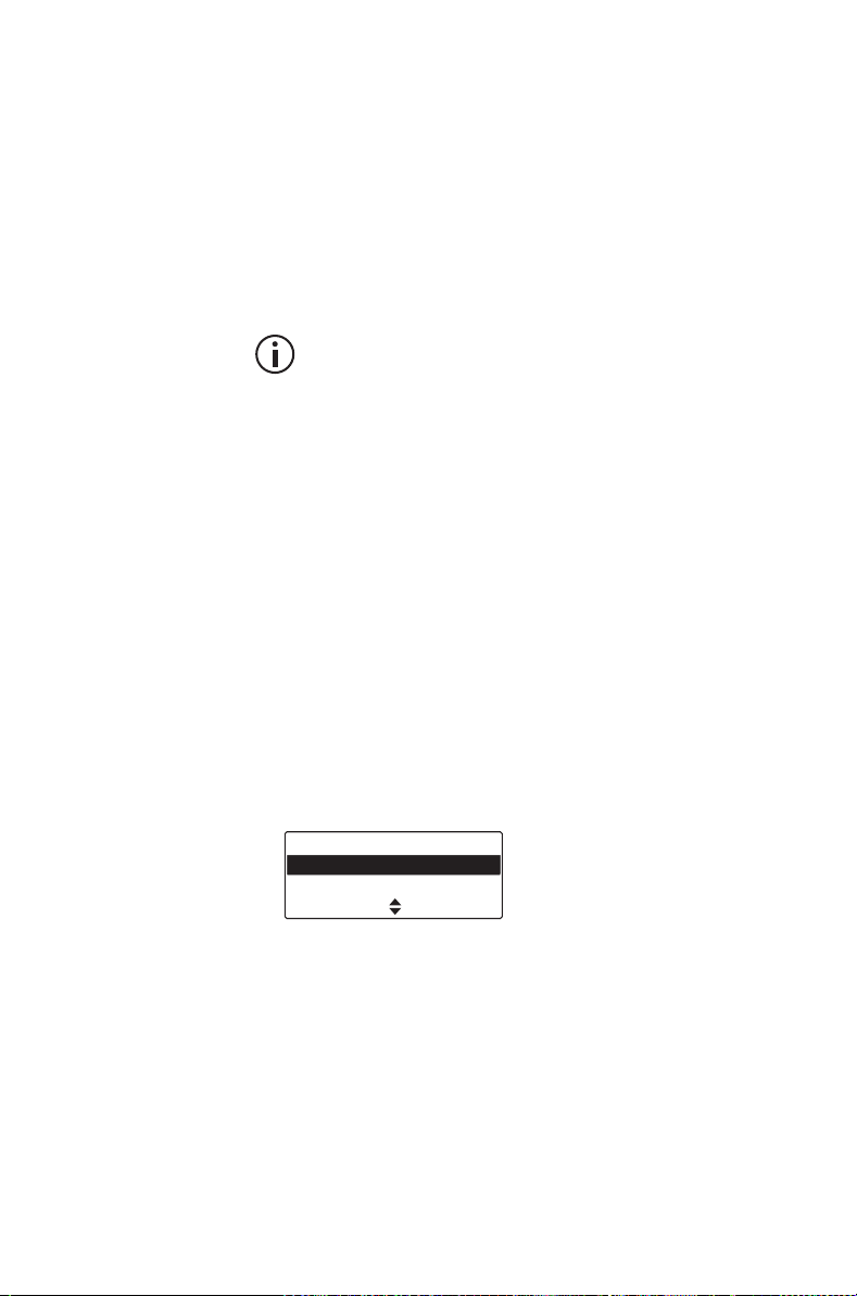
The radio warns you before the transmit timer expires
by beeping three times. The red status LED flashes
and the message Transmit timeout imminent
appears in the display.
The message Transmit Timeout Imminent appears
on the display.
If the transmit timer has timed out, you must release
the PTT before you can transmit again.
Your radio may be unable to transmit for a short
time after the transmit timer has expired.
Making an individual call
This feature is available for digital channels only.
To make a call to one person rather than a group of
people:
1 Press Menu and select Individual call.
(The person to whom you last made an individual
call is highlighted.)
(Depending on how your radio is programmed, you
may be able to press a function key or use your
Quick Access menu to select individual calls.)
2 Scroll to the person you want to call and press the
PTT key to make the call immediately.
Individual call
Car 2
Car 1
Back
Making a preset call
You may be able to use your radio to make preset
calls to an individual or a specific group using special
signaling known as ‘Selcall’.
Preset individual or group calls can be assigned to
each channel and/or function key.
To make a preset call:
78 Operating in conventional mode
Page 79
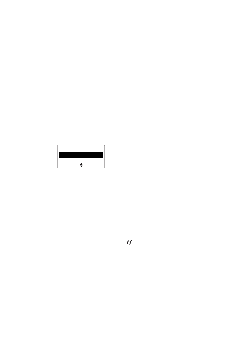
1 Select the required channel or group.
2 Press the programmed function key or PTT
(depending on your configuration).
Making a call using the
address book
The Address book menu has a programmed list of
calls, which can be made from any channel or zone.
Address-book calls may also be used to send status
information, such as “at lunch” or “on site”, or to
change to a channel or group.
Using the Main menu
1 Press Menu and select Address book.
Main menu
Address book
Local calls
(Depending on how your radio is programmed, you
may be able to use the scroll keys, left selection
key or a function key to select the Address book
menu.)
SelectBack
2 In the Address book menu, scroll through the list
of calls until the call you want appears.
3 Press Send.
The call details appear on the display, the red LED
glows LED glows red, and appears on the
display.
Operating in conventional mode 79
Page 80
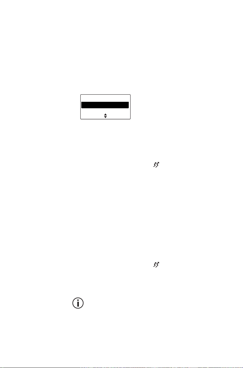
Making a local call
For analog channels, each channel on your radio may
have one or more local calls programmed.
Using the Main menu
1 Select the required channel.
2 Press Menu and select Local calls.
Main menu
Local calls
Set status
3 In the Local calls menu, scroll through the list of
local calls until the call you want appears.
4 Press Send.
The call details appear on the display, the red LED
glows LED glows red, and appears on the
display.
Using the Quick Access menu
1 Select the required channel.
SelectBack
2 Press one of the scroll keys or the left selection key
to open the Local calls menu.
3 Scroll through the list of local calls until the call you
want appears.
4 Press Send.
The call details appear on the display, the red LED
glows LED glows red, and appears on the
display.
Dialing a local call
This feature is only available for radios with
alphanumeric keys.
To make a local call to another radio or group of
radios:
1 Select the required channel.
80 Operating in conventional mode
Page 81

2 Press Menu and select Dial radio call.
Alternatively, your radio may be programmed so a
local call can be dialed directly from the default
display. In this case, you can start dialing the call
without selecting the menu option.
A series of X and S characters may appear,
prompting you to dial over them.
3 Dial the number using the alphanumeric keys.
Your radio may be programmed so you can dial
group tones using the and keys. Dial to
fill one X. Dial to fill the current X and all
subsequent X characters in the current burst.
4 Press Send (if the Send option appears).
The call details appear on the display, the red LED
glows LED glows red, and appears on the
display.
When the called party receives your call, the
message Ack received may appear on the
display.
Connecting to a telephone
network
For analog channels, you may be able to use your
radio to connect to a telephone network. This type of
call is known as a DTMF patch call.
To make a DTMF patch call, you may be able to
either:
■ use a programmed function key,
■ use the Main menu to dial the call,
■ make a local call (see "Making a local call" on
page 80), or
■ use your address book (see "Making a call using
the address book" on page 79).
Operating in conventional mode 81
Page 82
Using a function key
Depending on how DTMF patch calls are
programmed, some or the following steps may
not be necessary.
1 Select the required channel.
2 Press the function key programmed for DTMF
patch call.
Your radio may send tones to capture the line.
3 Press Send, or press the function key a second
time, to send the preset number.
You may hear telephone dialing and ringing tones.
4 Proceed with your call.
5 Press End, or give a long press on the function
key, to end the call.
Your radio may send tones to release the line.
Using the Main menu
This feature is only available for radios with
alphanumeric keys.
To dial a DTMF patch call by using the Main menu:
Depending on how DTMF patch calls are
programmed, some or the following steps may
not be necessary.
1 Select the required channel.
2 Press Menu and select Dial patch call.
3 Dial the required number using the alphanumeric
keys.
4 Press Send.
Your radio may send tones to capture the line.
5 Press Send to send the number dialed in step 3.
You may hear telephone dialing and ringing tones.
6 Proceed with your call.
82 Operating in conventional mode
Page 83

7 Once the call has finished, press End.
Your radio may send tones to release the line.
Making an emergency call
You may be able to activate emergency mode by
using a programmed function key.
1 Press the function key programmed for
Emergency Mode and an emergency call is sent to
your dispatcher, or some other predetermined
location.
While emergency mode is active, your radio may
cycle between receive and transmit, so that your
dispatcher can hear any activity near the radio.
Alternatively, your radio may appear to turn off but
will actually remain in emergency mode.
2 Reset the radio to normal operation at any time by
turning the radio off and then on.
Emergency mode may be programmed to end
after a fixed period of time. In this case, there is
no need to turn the radio off and then on in order
to return the radio to normal operation.
Sending a status message
For analog channels, your radio may be able to
maintain a record of your current status. This status
may be sent with outgoing calls programmed to
contain status information. If the radio receiving your
message has been programmed with the same status
messages, it will decode and display your message.
The message indicates your current activity or
location, such as “en route” or “at lunch”.
To change you current status:
Operating in conventional mode 83
Page 84
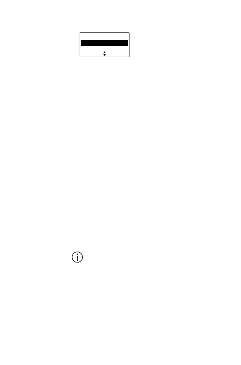
1 Press Menu and select Set status.
Main menu
Set status
Dial radio call
2 In the Set status menu, scroll through the list of
status messages until the message you
want appears.
3 Press Select. The message Status updated
appears on the display.
SelectBack
Resending calls automatically
Your radio may have been programmed to resend
individual and group calls when they are not
answered.
There are two automatic callback features:
■ deferred calling
■ no acknowledgement retries
Deferred calling
When you attempt to make a call on a channel that is
busy, the radio can store and send the call once the
channel is free. The radio gives a low-pitched beep if
the channel is busy, and then waits until the channel
is free to retry the call.
A deferred calling time limit may have been
configured. Once the time limit has expired the
radio will no longer attempt to retry the call.
To cancel a deferred call:
■ ress the PTT key.
No acknowledgement retries
When you send a call and there is no reply, the call is
resent.
84 Operating in conventional mode
Page 85

To cancel a call that is being resent:
■ Press the PTT key.
Transmitting at low power
If you are using your radio in conditions where signal
strength is high, you can extend the shift life of your
battery by transmitting at low power.
If you are using your radio in conditions where signal
strength is high, you can reduce the drain on your
vehicle battery by transmitting at low power.
When low power transmit is turned on, appears in
the display and calls are made at low power rather
than at the programmed power setting.
Some channels may always transmit at low power.
To turn low power transmit on or off for all channels:
Using the Main Menu
1 Press Menu and select Radio settings >
Functions > Low power tx.
(Depending on how your radio is programmed, you
may be able to press a function key to turn low
power transmit on or off.)
2 Scroll to On (or Off) and press Select. (The current
setting is highlighted.)
Low power tx
Off
On
The message Low power tx activated
(or deactivated) appears in the display.
Using a function key
1 Press the function key programmed for low-power
transmit to transmit at low power on your current
channel.
SelectBack
Operating in conventional mode 85
Page 86

The message Low power tx activated appears
briefly, and the low-power transmit icon appears
on the display.
2 Press the low-power transmit function key again to
turn low-power transmit off, and the message Low
power tx deactivated appears on the display.
Ending active calls
For analog channels, you may have a function key
programmed to either end the current call, or end the
current call and all other active calls in your group.
This can be done either by:
■ using the function key programmed for reset mon-
itor to end your current call,
■ using the function key programmed for call clear-
down to end your current call and all other calls in
your group, or
■ using the function key programmed for both reset
monitor and call cleardown.
Using a function key to end your current call
■ Press the function key programmed for reset mon-
itor. The radio’s monitor is turned off, ending your
current call.
The green LED stops flashingLED stops flashing
green, and the monitor icon disappears from the
display.
Using a function key to end all active calls
■ Press the function key programmed for call clear-
down and monitor is turned off for all radios in
your radio group.
The green LED stops flashingLED stops flashing
green, and the monitor icon disappears from the
display.
86 Operating in conventional mode
Page 87
Using the function key programmed for reset
monitor/call cleardown to end active calls
The function key programmed for reset monitor may
be programmed so that a short key press ends your
current call, and a long key press ends all active calls
in your group.
Using monitor and squelch
override (on analog channels)
The monitor function allows you to override some or
all of the radio’s mutes, and hear if there is any traffic
on a channel before you make a call.
The squelch override function lets the radio user
override the squelch (carrier) mute and hear all noise
on a channel, including weak signals that are below
the programmed squelch threshold.
Your radio may be programmed to activate
monitor whenever the microphone is off the
microphone clip.
To turn monitor on and off:
1 Press Menu and select Radio settings >
Functions > Monitor.
(Depending on how your radio is programmed, you
may be able to press a function key to toggle
monitor on and off.)
2 Scroll to On (or Off) and press Select.
While monitor is on, the green LED flashes
slowly LED slowly flashes green and the monitor
icon appears in the display.
Your radio may be programmed so that monitor
turns off automatically after a short time.
To turn squelch on and off:
1 Press Menu and select Radio settings >
Functions > Squelch o’ride.
Operating in conventional mode 87
Page 88

Squelch is often programmed as a long
keypress of the same function key that turns
monitor on and off.
2 Scroll to On (or Off) and press Select.
This allows you to hear even faint and noisy
signals. While squelch override is on, the green
LED flashes continuallyLED flashes green, and the
squelch override icon appears on the display.
Press the monitor function key again to return
the radio to a quiet state.
Squelch cannot be overridden when the radio is
scanning.
Bypassing the repeater
(on analog channels)
For analog channels, you can bypass the radio
repeater and communicate directly with another radio.
This feature is known as repeater talkaround. You can
do this, for example, when you are out of range of the
repeater, or if the repeater is busy or stops working.
While repeater talkaround is active, all transmissions
are made on the receive frequency of the channel you
are on.
To activate repeater talkaround, you may be able to
either use a programmed function key, or use the
Main menu.
Using the Main menu
1 Select the required channel.
2 Press Menu and select Radio settings >
Functions > Talkaround.
3 In the Talkaround menu, choose On.
4 Press Select. The message Talkaround
activated appears briefly, and the repeater
talkaround icon appears on the display.
88 Operating in conventional mode
Page 89

5 Proceed with your call.
6 To turn repeater talkaround off, either change the
channel, or choose Off in the Talkaround menu.
Using a function key
1 Select the required channel.
2 Press the programmed function key to turn
repeater talkaround on. The message Talkaround
activated appears briefly, and the repeater
talkaround icon appears on the display.
3 Proceed with your call.
4 To turn repeater talkaround off, either change the
channel, or press the function key again.
Receiving a call
When there is valid activity on your radio’s currently
selected channel or group, the radio then unmutes
and you can hear the call.
If an incoming analog call contains special signaling
that matches the signaling programmed for your radio,
the green LED flashesLED flashes green and your
radio may give a ringing tone.
Using the radio in different
repeater areas
Your radio may have a group of channels
programmed as a voting group. The channels in the
voting group all carry the same traffic, but from
different repeaters. As your radio moves in and out of
different repeater coverage areas, the best
communication channel is automatically selected for
you to use, until a better communications channel is
selected.
Operating in conventional mode 89
Page 90

This channel is known as the ‘home’ channel, and will
be the channel you make and receive calls on. While
voting is active, the orange LED glows and the
scanning icon appears on the display.
The section "Selecting a group" on page 73 explains
how to select a group. A group can be either a voting
or a scanning group.
Suspending a channel from a voting group
You may be able to use the function key programmed
for nuisance delete to temporarily delete one of the
channels from the voting group.
When that voting group is next selected, or after the
radio has been turned off and then on, the deleted
channel is again part of the voting group.
Alternatively, the function key programmed for voting
may be programmed so that a short key press turns
on voting, and a long key press activates nuisance
delete.
■ Press and hold the function key programmed for
voting to remove the current channel from the voting group.
If the operation has been successful, the message
Channel nuisance deleted appears on the
display.
Scanning a group of channels
The scan function is used to monitor a programmed
group of channels, looking for activity. While the radio
is scanning for activity, the orange LED glows and the
scanning icon appears on the display. When
activity is detected on a channel in the scan group, the
radio stops on that channel. The orange LED begins
flashing, the radio unmutes and you can hear the call.
Scanning resumes once the channel is no longer
busy.
90 Operating in conventional mode
Page 91

The section "Selecting a group" on page 73 explains
how to activate scanning.
Standard and background scanning
The two types of scanning that may be available on
your radio are standard scanning, and background
scanning. Background scan can only be activated by
using a function key programmed for background
scan. It differs from standard scanning in that the
channel that was selected when background scan
was activated is also included as a
scan-group member.
Making a call while scanning
If you wish to make a call while your radio is scanning:
1 Lift the microphone off the microphone clip.
2 Press the PTT key to transmit. If the orange LED is
flashing, or background scan is active, your radio
will now call the currently selected channel.
3 If standard scan is active and there has been no
recent activity on the channel (the orange LED is
glowing rather than flashing), then the channel that
is called depends on the way your radio has been
programmed. The possible options are:
■ your radio calls a predetermined channel e.g.
your
dispatcher,
■ your radio calls the channel where activity was
last
detected, or
■ your radio calls the last free channel.
4 When the called party responds, proceed with
your conversation.
Changing the background scan group
assigned to a function key
You can change the background scan group assigned
to the function key programmed for group scanning or
for scanning/nuisance delete.
Operating in conventional mode 91
Page 92
1 Press Menu and select Advanced > Set scan
key.
Advanced
Set scan key
Program groups
2 In the Set scan key menu, scroll through the list of
background scan groups until the group you
want appears.
3 Press Select.
The message Scan key scans new group
appears on the display.
The next time you activate background scan, the
new group will be your background scan group.
Suspending a channel from a scanning group
If a member channel of a scan group is busy for a long
time and you do not wish to hear the conversation, you
may be able to use the function key programmed for
nuisance delete to temporarily delete it from the scan
group.
When the scan group is next selected, or after the
radio has been turned off and then on, the deleted
channel is again part of the scan group.
SelectBack
Alternatively, the function key programmed for
scanning may be programmed so that a short key
press turns on scanning, and a long key press
activates nuisance delete.
■ Press and hold the function key programmed for
scanning to remove the current channel from the
scanning group.
If the operation has been successful, the message
Channel deleted from group appears on the display.
92 Operating in conventional mode
Page 93

Adding or deleting member channels of a
group
Your radio may be programmed so you can add or
delete channels in a voting or scanning group.
Changes made are permanent, and will remain after
restarting the radio.
1 Select the group. See "Selecting a group" on
page 73.
2 Press Edit.
If there is no edit option for the left selection key,
the group cannot be changed.
Alternatively, you may be able to edit groups by
pressing Menu and selecting Advanced >
Program groups, then select the group you wish
to edit.
3 In the Edit group menu, choose Add channel or
Delete channel.
4 Press Select.
5 Press the scroll keys to select the channel that you
want to add or delete.
6 Press OK.
If successful, the message Channel added or
Channel deleted appears.
To check the new group details, press Back
and select the Group members menu option.
Changing a group’s transmit channel
You may be able to change the transmit channel of a
standard scanning group. The transmit channel is
identified by the icon.
1 Select the group. See "Selecting a group" on
page 73.
2 Press Edit.
If there is no edit option for the left selection key,
the group cannot be changed.
Operating in conventional mode 93
Page 94

Alternatively, you may be able to edit groups by
pressing Menu and selecting Advanced >
Program groups, then select the group you wish
to edit.
3 In the Edit group menu, choose Change tx.
4 Press Select.
5 Press the scroll keys to select the new transmit
channel.
6 Press OK.
If successful, the message Tx channel changed
appears.
To check the new group details, press Back
and select the Group members menu option.
The new transmit channel has the icon next
to it.
Changing a group’s first or second priority
channel
You may be able to change the priority channels of a
scanning group. Priority channels are scanned more
frequently than other channels in the group. If valid
activity is found on another channel, the radio
continues to scan the priority channel or channels at
regular intervals. The first priority channel is identified
by the icon, and the second priority channel is
identified by the icon.
1 Select the group. See "Selecting a group" on
page 73.
2 Press Edit.
If there is no edit option for the left selection key,
the group cannot be changed.
Alternatively, you may be able to edit groups by
pressing Menu and selecting Advanced >
Program groups, then select the group you wish
to edit.
3 In the Edit group menu, choose Change P1 or
Change P2.
94 Operating in conventional mode
Page 95
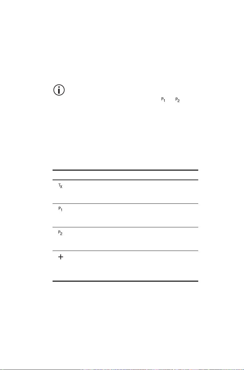
4 Press Select.
5 Press the scroll keys to select the new priority
channel.
6 Press OK.
If successful, the message P1 channel changed or
P2 channel changed appears.
To check the new group details, press Back
and select the Group members menu option.
The new priority channel has the or icon
next to it.
Icon and messages that may appear when
changing group details
The following icons may appear when viewing group
membership details, adding or deleting channels from
a group, or changing a group’s transmit or priority
channels.
Icon Meaning
This channel is used to transmit on when there has
been no recent activity. You cannot delete this
channel (it will not appear under Delete channel).
This channel is the group’s first priority channel. You
cannot delete this channel (it will not appear under
Delete channel).
This channel is the group’s second priority channel.
You cannot delete this channel (it will not appear
under Delete channel).
There is more than one instance of this channel in
the group (the channel will be scanned more often).
If you delete this channel, the radio will attempt to
delete all instances of the channel.
Operating in conventional mode 95
Page 96

The following messages may appear when using
nuisance delete to temporarily delete a channel from
a group, when adding or deleting channels from a
group, or changing a group’s transmit or priority
channels.
Message Meaning
Scanning not onYou cannot use nuisance delete to temporarily
delete a channel from a group, as there is no
group currently selected.
No channel
captured
Not enough
channels in
group
Cannot delete
channel
Cannot delete
priority chan
Only two
channels in
group
No items
in list
Group full You cannot add any more channels to the group,
You cannot use nuisance delete to temporarily
delete a channel from the group, as there is no
channel currently captured (the orange LED is
glowing and not flashing).
You cannot use nuisance delete to temporarily
delete the channel from the group, as the
captured channel is the last remaining group
member.
You cannot use nuisance delete to temporarily
delete the channel from the group. The captured
channel may be the selected channel in a
background scan group.
You cannot use nuisance delete to temporarily
delete the channel from the group, as the
captured channel is a priority channel.
You cannot delete a channel from the group, as
there would be only one group member left.
The action you are attempting is not allowed.
Either:
■ the group does not have a preset transmit
channel or priority channels programmed, or
■ you have added all the channels in the zone
to the current group.
as the maximum number of members (50) has
been reached.
96 Operating in conventional mode
Page 97

6 Operating in trunked
mode
This section explains how your radio operates on a
DMR (digital), MPT (analog) or dual-mode trunked
network.
These features are controlled by software
licenses (SFE) and may not be available with
your radio.
Your radio must have trunking functionality
programmed before it can operate in DMR or
MPT trunked mode.
This section covers:
■ Checking that your network is available
■ Changing your network
■ Making a preset call
■ About trunked zones and workgroups
■ About emergency operation
■ Dialing a PABX number
■ Dialing a PSTN number
■ Receiving a call
■ Re-establishing a call
■ Checking the queue
■ About status messages
■ About trunked text messages
■ Placing the radio in do-not-disturb mode
■ Calls to conventional channels or conventional
groups
Operating in trunked mode 97
Page 98

Checking that your network is
available
Check that the orange LED is glowing and the network
icon appears in the display. These are the
indications that your radio has access to a trunked
network.
Check that the orange LED is flashing and the
network icon appears on the display. These are the
indications that your radio has access to a trunked
network.
If the network icon is flashing and No service appears
on the display, your radio is attempting to access the
trunked network. If this icon remains flashing, your
radio may be out of the network coverage area.
If Limited service appears on the display, one of the
network sites or the connection between the network
sites has been interrupted. You can still make calls to
radios covered by the same site but not to radios to
other sites.
Changing your network
Your radio may be programmed to operate in up to
four completely separate trunking networks, either
DMR (digital), MPT (analog) or both (dual mode).
You may wish to change networks because you are
out of the network coverage area, or you need to have
access to another trunking network.
To change your radio’s operating network, you may
be able to either use the Main menu or dial the new
network using the alphanumeric keys.
Changing your radio’s workgroup may also
change the network in which you are operating.
See "Selecting a workgroup" on page 102.
98 Operating in trunked mode
Page 99
Using the Main menu
1 Press Menu and select Change network.
Main menu
Change network
Change mode
2 In the Change network menu, scroll through the
list of networks until the network you want appears.
3 Press Select.
The radio will restart and display the name of the
new network.
SelectBack
Dialing a new network
This feature is only available for radios with
alphanumeric keys.
1 Dial *700# to display the name of the current
trunked network.
2 Dial *70n# to change to a new network, where n is
the number of the new network (1 to 4).
The radio will restart and display name of the new
network.
Making a preset call
The preset calls programmed for your radio may be to
other radios, to PABX extensions or to PSTN
numbers.
1 Press Menu and select Preset calls.
Main menu
Preset calls
Set zone
(Depending on how your radio is programmed, you
may be able to use a function key, or left selection
key to select the Preset calls menu.)
SelectBack
Operating in trunked mode 99
Page 100

2 In the Preset calls menu, scroll through the list of
calls until the call you want appears, then press
Send.
While the call is being setup, you can cancel the
call by pressing Clear.
Dialing a preset call
This feature is only available for radios with
alphanumeric keys.
The preset calls programmed for your radio can be
dialed if you know the number associated with the
preset call.
1 Dial p, where p is the number of the preset call.
If your preset call number is the same as a call to
another radio, then you need to dial a leading 0.
For example, dial 23# to call radio 23 and dial 023#
for preset call number 23.
23
SendClear
2 Press Send or the # or PTT key.
While the call is being setup, you can cancel the
call by pressing Clear.
100 Operating in trunked mode
 Loading...