

TM8000 mobiles
TM8100 Mobile Radio
Service Manual
MM8100-02-00-812 Version 1.01
October 2003 © Tait Electronics Limited

Contact Information
Tait Radio Communications http://www.taitworld.com
Corporate Head Office
New Zealand
Tait Electronics Ltd
P.O. Box 1645
Christchurch
New Zealand
E-mail: info@taitworld.com
Website: http://www.taitworld.com
Technical Support:
E-mail: support@taitworld.com
Website: http://support.taitworld.com
Tait North America
Regional Head Office: United States of America
Tait North America Inc
E-mail: usa@taitworld.com
Canada
Tait North America Inc
E-mail: canada@taitworld.com
Latin America
Tait Latin America
E-mail: latinamerica@taitworld.com
Tait North Asia
Regional Head Office: Hong Kong
Tait Mobile Radio (Hong Kong) Ltd
E-mail: hongkong@taitworld.com
Beijing
Tait Mobile Radio (Hong Kong) Ltd
E-mail: beijing@taitworld.com
Tait South Asia
Regional Head Office: Singapore
Tait Electronics (Far East) Pte Ltd
E-mail: singapore@taitworld.com
Thailand
Tait Mobile Radio Ltd
E-mail: thailand@taitworld.com
Tait Oceania
New Zealand
Tait Communications Ltd
E-mail: headoffice@tcl.tait.co.nz
Australia
Tait Electronics (Aust) Pty Ltd
E-mail: australia@taitworld.com
Tait Europe
Regional Head Office: United Kingdom
Tait Mobile Radio Ltd
E-mail: teusales@tait.co.uk
2 TM8100 Mobile Radio Service Manual
Note
For the addresses and telephone numbers of the
above regional offices refer to the TaitWorld
website.
October 2003 © Tait Electronics Limited

Tait General Software Licence Agreement
This legal document is an Agreement between
you (the “Licensee”) and Tait Electronics Limited
(“Tait”). By using any of the Software or
Firmware items prior-installed in the related Tait
product, included on this CD or downloaded
from the Tait website, (hereinafter referred to as
“the Software or Firmware”) you agree to be
bound by the terms of this Agreement. If you do
not agree to the terms of this Agreement, do not
install and use any of the Software or Firmware.
If you install and use any of the Software or
Firmware that will be deemed to be acceptance of
the terms of this licence agreement.
The terms of this agreement shall apply subject
only to any express written terms of agreement to
the contrary between Tait and the Licensee.
Licence
TAIT GRANTS TO YOU AS LICENSEE THE NON-
EXCLUSIVE RIGHT TO USE THE SOFTWARE OR
FIRMWARE ON A SINGLE MACHINE PROVIDED YOU
MAY ONLY
1. COPY THE SOFTWARE OR FIRMWARE INTO ANY
MACHINE READABLE OR PRINTED FORM FOR
BACKUP PURPOSES IN SUPPORT OF YOUR USE OF
THE PROGRAM ON THE SINGLE MACHINE
PROGRAMS
TO LIMIT OR INHIBIT COPYING
“
COPY PROTECTED”), PROVIDED THE COPYRIGHT
NOTICE MUST BE REPRODUCED AND INCLUDED ON
ANY SUCH COPY OF THE SOFTWARE OR FIRMWARE
AND / OR
2. MERGE IT INTO ANOTHER PROGRAM FOR YOUR
USE ON THE SINGLE MACHINE
ANY SOFTWARE OR FIRMWARE MERGED INTO
ANOTHER PROGRAM WILL CONTINUE TO BE
SUBJECT TO THE TERMS AND CONDITIONS OF THIS
AGREEMENT
THE LICENSEE MAY NOT DUPLICATE, MODIFY,
REVERSE COMPILE OR REVERSE ASSEMBLE ANY
SOFTWARE OR FIRMWARE IN WHOLE OR PART
:
(CERTAIN
, HOWEVER, MAY INCLUDE MECHANISMS
, THEY ARE MARKED
(ANY PORTION OF
).
.
Title to Software
THIS AG REEMENT DOES NOT CONSTITUTE A
CONTRACT OF SALE IN RELATION TO THE
SOFTWARE OR FIRMWARE SUPPLIED TO THE
LICENSEE
OWN THE MAGNETIC OR OTHER PHYSICAL MEDIA
ON WHICH THE SOFTWARE OR FIRMWARE WAS
ORIGINALLY SUPPLIED
BEEN RECORDED OR FIXED
TERM OF THIS AG REEMENT THAT AT ALL TIMES
TITLE AND OWNERSHIP OF THE SOFTWARE OR
FIRMWARE
OTHERWISE
THIRD PARTIES WHO HAVE GRANTED LICENCES TO
TAIT
. NOT WITHSTANDING THE LICENSEE MAY
, OR HAS SUBSEQUENTLY
, IT IS A FUNDAMENTAL
, WHETHER ON THE ORIGINAL MEDIA OR
, SHALL REMAIN VESTED IN TAIT OR
.
Term and Termination
THIS LICENCE SHALL BE EFFECTIVE UNTIL
TERMINATED IN ACCORDANCE WITH THE
PROVISIONS OF THIS AGREEMENT
MAY TERMINATE THIS LICENCE AT ANY TIME BY
DESTROYING ALL COPIES OF THE SOFTWARE OR
FIRMWARE AND ASSOCIATED WRITTEN MATERIALS
THIS LICENCE WILL BE TERMINATED
AUTOMATICALLY AND WITHOUT NOTICE FROM
TAIT IN THE EVENT THAT THE LICENSEE FAILS TO
COMPLY WITH ANY TERM OR CONDITION OF THIS
AGREEMENT
ALL COPIES OF THE SOFTWARE OR FIR MWARE AND
ASSOCIATED WRITTEN MATERIALS IN THE EVENT OF
SUCH TER MINATION
;
Limited Warranty
THE SOFTWARE OR FIRMWARE IS SUPPLIED BY TAIT
AND ACCEPTED BY THE LICENSEE
WARRANTY OF ANY KIND EITHER EXPRESSED OR
IMPLIED
ANY IMPLIED WARRANTIES AS TO
MERCHANTABILITY OR FITNESS FOR ANY
PARTICULAR PURPOSE
ACKNOWLEDGES THAT THE SOFTWARE OR
FIRMWARE IS USED BY IT IN BUSINESS AND
ACCORDINGLY TO THE MAXIMUM EXTENT
PERMITTED BY LAW NO TER MS OR WARRANTIES
WHICH ARE IMPLIED BY LEGISLATION SHALL APPLY
TO THIS AGREEMENT
THAT THE FUNCTIONS CONTAINED IN THE
SOFTWARE OR FIRMWARE WILL MEET THE
LICENSEE
OPERATION OF THE SOFTWARE OR FIRMWARE WILL
BE UNINTERRUPTED OR ERROR
. THE LICENSEE AGREES TO DESTROY
.
, INCLUDING BUT NOT BEING LIMITED TO
. THE LICENSEE
. TAIT DOES NOT WARRANT
’S REQUIREMENTS OR THAT THE
. THE LICENSEE
.
“AS IS” WITHOUT
-FREE.
TM8100 Mobile Radio Service Manual 3
October 2003 © Tait Electronics Limited

Exclusion of Liability
TAIT’S ENTIRE LIABILITY AND THE LICENSEE’S
EXCLUSIVE REMEDY SHALL BE THE FOLLOWING
:
1. IN NO CIRCUMSTANCES SHALL TAIT BE UNDER
ANY LIABILITY TO THE LICENSEE
PERSON WHATSOEVER
SEQUENTIAL DAMAGE ARISING OUT OF OR IN CON-
NECTION WITH ANY USE OR INABILITY OF USING
THE SOFTWARE OR FIRMWARE
, FOR ANY DIRECT OR CON-
, OR ANY OTHER
.
2. TAIT WARRANTS THE OPERATION OF THE
SOFTWARE OR FIRMWARE ONLY WITH THE
OPERATING SYSTEM FOR WHICH IT WAS DESIGNED
USE OF THE SOFTWARE OR FIR MWARE WITH AN
OPERATING SYSTEM OTHER THAN THAT FOR
WHICH IT WAS DESIGNED MAY NOT BE SUPPORTED
BY TAIT
TAIT
, UNLESS OTHERWISE EXPRESSLY AGREED BY
.
General
THE LICENSEE CONFIRMS THAT IT SHALL COMPLY
WITH THE PROVISIONS OF LAW IN RELATION TO THE
SOFTWARE OR FIRMWARE
.
Law and Jurisdiction
THIS AGREEMENT SHALL BE SUBJECT TO AND
CONSTRUED IN ACCORDANCE WITH NEW ZEALAND
LAW AND DISPUTES BETWEEN THE PARTIES
CONCERNING THE PROVISIONS HEREOF SHALL BE
DETERMINED BY THE NEW ZEALAND COURTS OF
LAW
. PROVIDED HOWEVER TAIT MAY AT ITS
ELECTION BR ING PROCEEDINGS FOR BREACH OF
THE TER MS HEREOF OR FOR THE ENFORCEMENT
OF ANY JUDGEMENT IN RELATION TO A BREACH OF
THE TER MS HEREOF IN ANY JURISDICTION TAIT
CONSIDERS FIT FOR THE PURPOSE OF ENSURING
COMPLIANCE WITH THE TERMS HEREOF OR
OBTAINING RELIEF FOR BREACH OF THE TERMS
HEREOF
.
No Other Terms
THE LICENSEE ACKNOWLEDGES THAT IT HAS READ
THIS AG REEMENT
TO BE BOUND BY ITS TERMS AND CONDITIONS
LICENSEE FURTHER AGREES THAT SUBJECT ONLY
TO ANY EXPRESS WRITTEN TERMS OF AGREEMENT
TO THE CONTRARY BETWEEN TAIT AND THE
LICENSEE THIS IS THE COMPLETE AND EXCLUSIVE
STATEMENT OF THE AGREEMENT BETWEEN IT AND
TAIT IN RELATION TO THE SOFTWARE OR
FIRMWARE WHICH SUPERSEDES ANY PROPOSAL OR
.
PRIOR AGREEMENT
OTHER COMMUNICATIONS BETWEEN THE LICENSEE
AND TAIT RELATING TO THE SOFTWARE OR
FIRMWARE
, UNDERSTANDS IT AND AGREES
. THE
, ORAL OR WRITTEN AND ANY
.
No Dealings
THE LICENSEE MAY NOT SUBLICENSE, ASSIGN OR
TRANSFER THE LICENCE OR THE PROGRAM EXCEPT
AS EXPRESSLY PROVIDED IN THIS AGREEMENT
ATTEMPT OTHERWISE TO SUBLICENSE
TRANSFER ANY OF THE R IGHTS
OBLIGATIONS HEREUNDER IS VOID
, ASSIGN OR
, DUTIES OR
.
4 TM8100 Mobile Radio Service Manual
. ANY
October 2003 © Tait Electronics Limited

Contents
Preface. . . . . . . . . . . . . . . . . . . . . . . . . . . . . . . . . . . . . . . . . . . . . . . . . . . . . . . . . . . . .6
Notes for Readers . . . . . . . . . . . . . . . . . . . . . . . . . . . . . . . . . . . . . . . . . . . . . . . . . . . . 7
Typographical Conventions . . . . . . . . . . . . . . . . . . . . . . . . . . . . . . . . . . . . . . . . . . . . . . 8
Associated Documents . . . . . . . . . . . . . . . . . . . . . . . . . . . . . . . . . . . . . . . . . . . . . . . . . 9
Amendment Record. . . . . . . . . . . . . . . . . . . . . . . . . . . . . . . . . . . . . . . . . . . . . . . . . . 10
List of Acronyms . . . . . . . . . . . . . . . . . . . . . . . . . . . . . . . . . . . . . . . . . . . . . . . . . . . . 11
1 Introduction . . . . . . . . . . . . . . . . . . . . . . . . . . . . . . . . . . . . . . . . . . . . . . . 13
1.1 TM8100 Mobile Radio System . . . . . . . . . . . . . . . . . . . . . . . . . . . . . . . . . . . . . . 13
1.2 Radio Body. . . . . . . . . . . . . . . . . . . . . . . . . . . . . . . . . . . . . . . . . . . . . . . . . . . . . 19
1.3 Control Head . . . . . . . . . . . . . . . . . . . . . . . . . . . . . . . . . . . . . . . . . . . . . . . . . . . 21
1.4 Repair Levels. . . . . . . . . . . . . . . . . . . . . . . . . . . . . . . . . . . . . . . . . . . . . . . . . . . . 22
1.5 Product Codes. . . . . . . . . . . . . . . . . . . . . . . . . . . . . . . . . . . . . . . . . . . . . . . . . . . 23
2 General Description . . . . . . . . . . . . . . . . . . . . . . . . . . . . . . . . . . . . . . . . . . 27
2.1 Architecture of Radio . . . . . . . . . . . . . . . . . . . . . . . . . . . . . . . . . . . . . . . . . . . . . 27
2.2 Operation of Control-head Circuitry . . . . . . . . . . . . . . . . . . . . . . . . . . . . . . . . . . 29
2.3 Operation in Receive Mode. . . . . . . . . . . . . . . . . . . . . . . . . . . . . . . . . . . . . . . . . 31
2.4 Operation in Transmit Mode . . . . . . . . . . . . . . . . . . . . . . . . . . . . . . . . . . . . . . . . 34
2.5 Operation of Frequency Synthesizer . . . . . . . . . . . . . . . . . . . . . . . . . . . . . . . . . . . 37
3 Disassembly and Re-assembly of Radio . . . . . . . . . . . . . . . . . . . . . . . . . . . . 39
3.1 Detachment of Control Head. . . . . . . . . . . . . . . . . . . . . . . . . . . . . . . . . . . . . . . . 41
3.2 Disassembly of Control Head . . . . . . . . . . . . . . . . . . . . . . . . . . . . . . . . . . . . . . . . 45
3.3 Disassembly of Radio Body . . . . . . . . . . . . . . . . . . . . . . . . . . . . . . . . . . . . . . . . . 51
3.4 Re-assembly of Radio Body. . . . . . . . . . . . . . . . . . . . . . . . . . . . . . . . . . . . . . . . . 58
3.5 Re-assembly and Attachment of Control Head . . . . . . . . . . . . . . . . . . . . . . . . . . . 61
TM8100 Mobile Radio Service Manual 5
October 2003 © Tait Electronics Limited

Preface
Scope of service manual This manual provides information to service technicians for carrying out
level-1 repairs of TM8100 mobile radios. Level-1 repairs entail the
replacement of faulty parts and circuit boards.
The manual does not cover level-2 repairs (repair of circuit boards, with
the exception of certain special items on the boards) and level-3 repairs
(repair of the special items).
The servicing procedures are moreover limited to the control head and
radio body of TM8100 mobile radios. Servicing of all accessories
associated with the radio is covered in the accessories manual.
Summary of service manual The service manual is divided into three sections. The first section
introduces the radio. The main products making up the radio system are
identified (in particular, the control head and radio body), the repair
levels are discussed, and the product codes of the control head and radio
body are given.
In the second section the functioning of the radio is described. The
description is limited to the control head and radio body. The
architecture of the radio, the operation of the control-head circuitry, the
functioning of the radio in the receive and transmit modes, and the
operation of the frequency synthesizer are described.
The third section provides information regarding the level-1 repair
procedures. The information is mainly limited to the procedures for
disassembling and re-assembling the radio. Only a brief outline is given
of the overall repair procedures themselves.
6 TM8100 Mobile Radio Service Manual
October 2003 © Tait Electronics Limited

Notes for Readers
Enquiries and comments Any enquiries regarding this manual or the equipment that it describes,
as well as any comments, suggestions and notifications of errors, should
be addressed by e-mail to Technical Support (support@taitworld.com
or to the Technical Support Manager, Tait Electronics Limited, PO Box
1645, Christchurch, New Zealand. Orders for this manual can be placed
with your Tait Dealer.
)
Updates of manual
and equipment
In the interests of improving the performance, reliability or servicing of
the equipment, Tait Electronics Limited reserves the right to upgrade the
equipment or update this manual or both without prior notice.
Copyright All information contained in this manual is the property of Tait
Electronics Limited. All rights are reserved. This manual may not, in
whole or in part, be copied, photocopied, reproduced, translated, stored,
or reduced to any electronic medium or machine-readable form,
without prior written permission from Tait Electronics Limited. All
trade names referenced are the service mark, trade mark, or registered
trade mark of the respective manufacturers.
Disclaimer There are no warranties extended or granted by this manual. Tait
Electronics Limited accepts no responsibility for damage arising from use
of the information contained in the manual or of the equipment and
software it describes. It is the responsibility of the user to ensure that use
of such information, equipment and software complies with the laws,
rules and regulations of the applicable jurisdictions.
TM8100 Mobile Radio Service Manual 7
October 2003 © Tait Electronics Limited
Typographical Conventions
Conventions and alerts In this manual the names of electrical signals are typed in small capitals
using the standard sans-serif font of the document. For example:
TX INHIBIT
Alert notices that appear in the manual are selected from whichever of
the following are appropriate. These alert notices are in accordance with
the ANSI definitions.
Warning!! This alert notice is used when there is a
potential risk of death or serious injury.
Caution This alert notice is used when there is a risk of
minor to moderate injury to people.
Important This alert notice is used to warn about the risk of
equipment damage or malfunction.
Note This alert notice is used to highlight information that is
required to ensure that procedures are performed correctly.
8 TM8100 Mobile Radio Service Manual
October 2003 © Tait Electronics Limited

Associated Documents
Basic manuals Together with this service manual, the following manuals are of concern
to service technicians. The pair of digits in the third field of the
document product code indicates the language of the document — 00
indicates an English and 03 a multi-lingual document.
MM8100-00-03-804
TM8100 mobile radio — User’s guide
MMAA00-00-00-812
TM8100 mobile radio — Accessories manual
PCB information packages Information on the circuit boards is supplied in the following separate
documents. The information consists of the BOMs (parts lists), grid
reference indexes, PCB layouts, and circuit diagrams.
MMAB12-H5-00-814
Main board (H5/H6) — PCB information package
MMAB12-B1-00-814
Main board (B1) — PCB information package
MMAC20-00-00-814
Control-head board — PCB information package
3DK manuals The following manuals are mainly of concern to third-party developers.
The manuals are supplied in soft-copy form on a 3DK resource CD.
MMAA30-00-00-807
TM8000 3DK hardware developer’s kit — Application manual
MMAA30-02-00-429
TM8000 3DK application board — Software programmer’s manual
MMAA30-02-00-812
TM8000 3DK application board — Service manual
MM8100-00-00-441
TM8100 Computer-controlled data interface — Protocol definition
TM8100 Mobile Radio Service Manual 9
October 2003 © Tait Electronics Limited

Amendment Record
Version Publication date Amended sections and pages
1.00 September 2003 First release
1.01 October 2003 Alert notice added in Section 3
Figures 3.5 to 3.8 updated
10 TM8100 Mobile Radio Service Manual
October 2003 © Tait Electronics Limited

List of Acronyms
3DK Third-party Developer’s Kit
AC Alternating Cur rent
ACP Adjacent Channel Power
ADC Analogue-to-digital Converter
AGC Automatic Gain Control
ALC Automatic Level Control
ASC Accredited Service Centre
BOM Bill of Materials
CODEC Coder-decoder
CSO Customer Service Organisation
DAC Digital-to-analogue Converter
DC Direct Current
DIN Deutsche Industrie Norm
DSP Digital Signal Processor
DTMF Dual-tone Multi-frequency
FCL Frequency Control Loop
FPGA Field-programmable Gate Array
IPN Internal Part Number
IC Integrated Circuit
IF Intermediate Frequency
IQ In-phase and Quadrature
ISC International Service Centre
LCD Liquid-crystal Display
LED Light-emitting Diode
LO Local Oscillator
PA Power Amplifier
PCB Printed Circuit Board
PLL Phase-locked Loop
RF Radio Frequency
RSSI Received Signal Strength Indication
SMT Surface-mount Technology
TCXO Temperature-compensated Crystal Oscillator
TEL Tait Electronics Limited
UHF Ultra-high Frequency
VCO Voltage-controlled Oscillator
VCXO Voltage-controlled Crystal Oscillator
VHF Very High Frequency
TM8100 Mobile Radio Service Manual 11
October 2003 © Tait Electronics Limited

12 TM8100 Mobile Radio Service Manual
October 2003 © Tait Electronics Limited

1 Introduction
Scope of section This section introduces the TM8100 mobile radio system. The main
items making up the system are first introduced. There follows
additional information on the radio body and control head — the two
items that are the prime concern of the service manual. Next is a
discussion of the repair levels that govern the servicing of the radio body
and control head. The section concludes with an explanation of the
product codes for these items.
1.1 TM8100 Mobile Radio System
Main items of system The TM8100 mobile radio system is a high-performance
microprocessor-controlled transceiver with a comprehensive range of
accessories. The system is designed primarily for installation in vehicles
but can also be used in desktop, remote-monitoring and similar
applications. The system consists of the following main items:
■ radio body
■ control head
■ audio accessories
■ mounting for radio
■ desktop power supply (optional)
The service manual covers the servicing of the radio body and control
head only. The accessories manual covers servicing of all the remaining
items.
Specifications for system The specifications for the system are not given in this manual, but will
be found instead on the TaitWorld website in the area reserved for
TM8000 products. This ensures that the latest specification data will
always be available to service technicians.
Radio body The radio body contains the transmitter, receiver and microprocessor
circuitry. The radio body also allows for the fitting of an internal options
board to provide additional functions. There are three standard external
connectors on the radio body: an RF connector, power connector, and
auxiliary connector. If an internal options board is fitted, there might or
might not be an associated external options connector. The auxiliary
and external options connectors allow for the connection of various
external devices.
TM8100 Mobile Radio Service Manual Introduction 13
October 2003 © Tait Electronics Limited
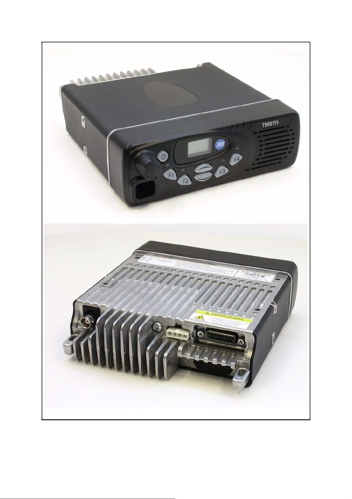
Figure 1.1 Illustrations of the TM8115 mobile radio showing both the front and rear
14 Introduction TM8100 Mobile Radio Service Manual
October 2003 © Tait Electronics Limited
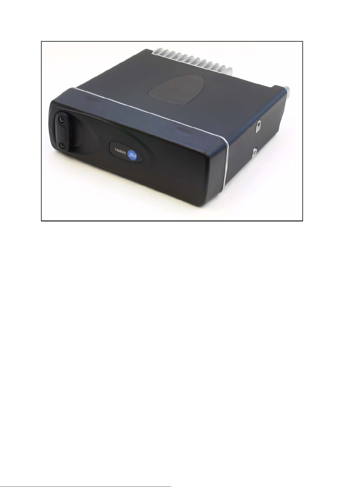
Figure 1.2 Illustration of the front of the TM8105 mobile radio
Control head
The control head is attached to the radio body. There is a choice of two
control heads:
■ two-digit-display control head
■ blank control head
The two-digit display control head provides the interface with the radio
user and includes a socket for the connection of a microphone. The
blank control head has no user interface but has a single external
connector called the programming connector; this is typically used for
programming and monitoring purposes. The radio is designated
TM8115 with the two-digit-display control head and TM8105 with the
blank control head. Illustrations of these radios are given in Figure 1.1
and Figure 1.2.
Audio accessories One or more audio accessories may be connected to the control head
and radio body. A microphone is the accessory usually required; other
accessories that are available are a handset, high-power remote speaker,
and hands-free kit. Various external devices may also be connected. The
user’s guide and accessories manual describe the audio accessories.
TM8100 Mobile Radio Service Manual Introduction 15
October 2003 © Tait Electronics Limited
RF ANTENNA
RF
CONNECTOR
DEVICE
EXTERNAL
FREE
HANDS-
EXTERNAL OPTIONS
CONNECTOR
AUXILIARY
RADIO BODY
KIT
CONNECTOR
FUSES
POWER
CONNECTOR
VEHICLE
HIGH-
POWER
BATTERY
REMOTE
SPEAKER
RADIO SYSTEM
CONTROL
HEAD
CONNECTOR
MICROPHONE
PHONE
MICRO-
MOUNTING
PLATE
HANGER
dwls
Figure 1.3 Block diagram of an example installation of the TM8115 mobile radio in a vehicle
16 Introduction TM8100 Mobile Radio Service Manual
October 2003 © Tait Electronics Limited
RF ANTENNA
DEVICE
EXTERNAL
BACK-UP
BATTERY
AC MAINS
RF
CONNECTOR
RADIO SYSTEM
CONTROL
AUXILIARY
RADIO BODY
HEAD
EXTERNAL OPTIONS
CONNECTOR
CONNECTOR
POWER
CONNECTOR
CONNECTOR
MICROPHONE
DESKTOP POWER SUPPLY
OR
MICRO-
DESKTOP
HANDSET
PHONE
Figure 1.4 Block diagram of an example desktop installation of the TM8115 mobile radio
TM8100 Mobile Radio Service Manual Introduction 17
October 2003 © Tait Electronics Limited
dwls
RF ANTENNA
DEVICE
EXTERNAL
DEVICE
EXTERNAL
FUSES
VEHICLE
BATTERY
RF
CONNECTOR
EXTERNAL OPTIONS
RADIO SYSTEM
CONNECTOR
RADIO BODY
BLANK
CONTROL
HEAD
AUXILIARY
CONNECTOR
POWER
CONNECTOR
CONNECTOR
PROGRAMMING
MOUNTING
DEVICE
EXTERNAL
Figure 1.5 Block diagram of an example installation of the TM8105 mobile radio in a vehicle
18 Introduction TM8100 Mobile Radio Service Manual
October 2003 © Tait Electronics Limited
dwls

Installation kits and
desktop power supply
The mounting hardware for the radio is in the form of a U-cradle. It is
supplied in an installation kit and provides for the installation of the radio
in a vehicle. Alternatively, the radio might be needed for desktop use, in
which case a desktop power supply is required. In some desktop
installations the U-cradle is used to attach the radio to the power supply.
The user’s guide and accessories manual describe the installation kit.
Block diagrams of system The block diagrams of Figure 1.3 to Figure 1.5 illustrate possible
configurations of the radio system. Figure 1.3 and Figure 1.4 show
example installations of the TM8115 radio (with two-digit-display
control head) in a vehicle and on a desktop. Figure 1.5 shows an example
of the TM8105 radio (with blank control head) installed in a vehicle.
Different audio accessories are shown connected to the radio. The
hands-free kit is connected to the auxiliary connector, and the remote
speaker to the power connector. The accessories that may be connected
to the microphone connector include the rugged microphone, as well as
a DTMF microphone, desktop microphone, and handset.
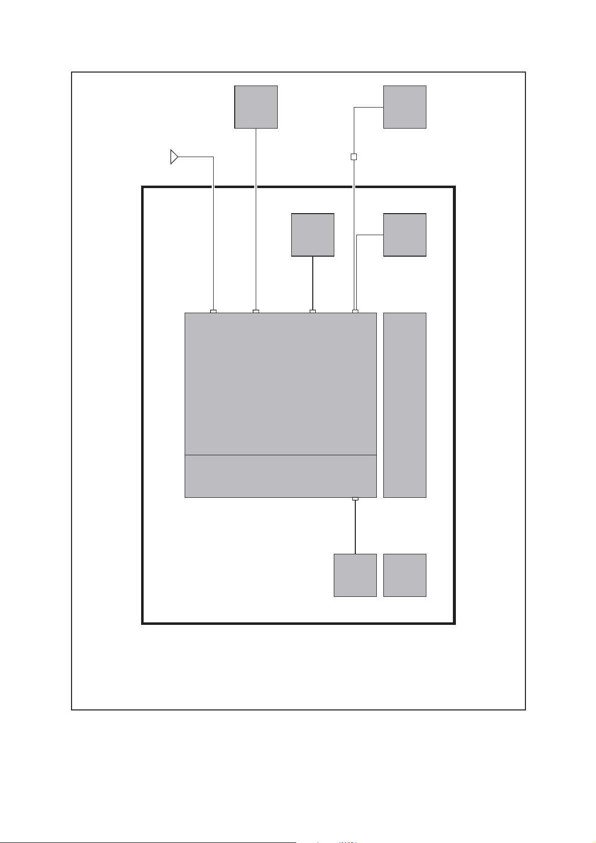
1.2 Radio Body
Main, digital and
internal options boards
The radio body consists of a rectangular case — or chassis — with a lid.
The case houses a main board with the receiver and transmitter circuitry,
and a digital board with the microprocessor that controls the radio.
There are different main boards available covering different frequency
bands and with different RF performances; refer to the product codes in
Figure 1.8. The digital board is reflow-soldered to the main board.
There is space in the lid for an optional internal options board. The
essentials of the arrangement are illustrated in the block diagram of
Figure 1.6.
Main-board assembly The rear edge of the main board is attached to a heat-transfer block. The
block is in thermal contact with the rear of the case, where there are
cooling fins for heat dissipation. Heat from the output stage of the
transmitter is conducted via the heat-transfer block to the rear and
radiated from the cooling fins. (The lower surface of the case is ridged
to augment the dissipation of heat.) The RF, auxiliary and power
connectors are fixed to the rear of the main board. They project through
apertures in the heat-transfer block and the rear of the case. The main
board, digital board, and heat-transfer block constitute a separate unit
called the main-board assembly.
Internal options boards Either Tait-designed or custom internal options boards may be fitted in
the radio body. Full details of the boards are given in the accessories
and 3DK manuals. Any internal options board that is fitted might or
might not include an external options connector. If included, the
connector will project through an aperture in the rear of the lid. If there
is no connector, the aperture is sealed with a bung.
TM8100 Mobile Radio Service Manual Introduction 19
October 2003 © Tait Electronics Limited

Figure 1.6 Block diagram of the radio body and control head of the TM8115 mobile radio
20 Introduction TM8100 Mobile Radio Service Manual
October 2003 © Tait Electronics Limited

Internal connections
There are three sets of internal connections to the main board; these use
the following connectors:
■ debug connector
■ control-head connector
■ internal options connector
The debug connector is for Factory use only. The control-head
connector is on the front edge of the main board; it is used to connect a
control-head loom from the control head to the main board. The
internal options connector is required when an internal options board is
fitted; it is used to connect an options loom between the two boards.
1.3 Control Head
Introduction The control head clips securely to the front of the radio body. The
control-head loom between the two is enclosed in the space between
them. For badging and branding purposes there are both a logo and a
label for the product model code on the front panel. The control head
may also be left unbadged. The essentials of the two-digit-display
control head are shown in the block diagram of Figure 1.6.
Two-digit-display control head The front panel of the two-digit-display control head is fitted with the
controls and indicators needed by the radio user; these comprise:
■ LCD screen
■ indicator LEDs
■ volume control
■ on/off key
■ function keys
■ channel-selection keys
In addition, there are the microphone connector and an internal speaker.
The necessary circuitry for the above items is mounted on a control-head
board fitted behind the front panel. The volume-control potentiometer
is fixed to the board; so is a control-head connector, which is used for
the control-head loom between the control head and radio body.
Options for control head The two-digit-display control head allows for an optional concealed
microphone or the use of a dynamic microphone. (A concealed
microphone is fitted behind the front panel next to the speaker.) With
either option a separate circuit board is required for the microphone.
This board is connected to the control-head board by means of two
connectors; the plugs of the connectors are mounted on the latter board
and the sockets on the former. Full details of the optional microphones
and circuit board are given in the accessories manual.
TM8100 Mobile Radio Service Manual Introduction 21
October 2003 © Tait Electronics Limited

Blank control head
The blank control head has none of the features of the two-digit-display
control head. The front panel of the blank control head is fitted only
with the single programming connector. The control-head loom is
permanently fixed to the rear of the programming connector. The space
inside the control head can be used for the fitting of an optional thirdparty circuit board, but is otherwise empty.
1.4 Repair Levels
Level-1 repairs The repairs that can be carried out on the TM8100 mobile radio are
grouped into categories — or levels — of increasing complexity. This
manual covers only level-1 repairs, which comprise the following:
■ replacement of control-head board
■ replacement of main-board assembly
■ replacement of other parts
The last-named parts include the connectors and volume-control
potentiometer on the control-head board, but not the connectors on the
main board.
Level-2 repairs It is important to distinguish level-1 repairs from the higher-level repairs,
which require greater skills and resources. Thus, level-2 repairs comprise
the following:
■ repair of control-head board
■ repair of main-board assembly, excluding special items
These repairs entail the replacement of faulty SMT components on the
boards, as well as the connectors on the main board. The special items
are the digital board and certain components on the main board.
(Repairs of the special items are level-3 repairs.)
Service centres The service centres that carry out repairs of TM8100 mobile radios can
be divided into three categories:
■ Dealers and Customers with appropriate facilities
■ ASCs, including CSOs
■ TEL and ISC
ASCs, the ISC and TEL may carry out both level-1 and level-2 repairs.
These are moreover the only service centres that may repair a radio that
is still under warranty — any repair by a non-accredited service centre
will void the warranty. After the expiry of the warranty, Dealers and
Customers with appropriate facilities may also carry out level-1 repairs,
but are strongly advised not to attempt level-2 repairs. Contact Technical
Support for details of the process by which service centres may achieve
accreditation.
22 Introduction TM8100 Mobile Radio Service Manual
October 2003 © Tait Electronics Limited

Figure 1.7 Scheme for the product codes assigned to products of the mobile radio product line
Restrictions regarding
level-3 repairs
Only TEL and the ISC should carry out level-3 repairs. The level of
technology employed in the TM8100 generation of radios is an order of
magnitude greater than in earlier generations. This greater sophistication
demands special equipment and techniques for level-3 repairs. Although
other service centres are strongly advised not to attempt such repairs,
those with sufficient resources and skilled technicians may wish to do so.
These service centres should contact Technical Support for assistance and
for the necessary documentation. TEL does not offer accreditation for
level-3 repairs to any service centres other than the ISC.
1.5 Product Codes
Introduction This subsection describes the product codes used to identify different
products of the mobile radio product line. The product-code scheme in
general is first explained, and then the product codes for the radio body
and control head in particular. The purpose is solely to enable service
technicians to identify the radio body and control head of a radio that has
been delivered for repair.
TM8100 Mobile Radio Service Manual Introduction 23
October 2003 © Tait Electronics Limited

Figure 1.8 Scheme for the product codes currently in use for the radio body of TM8100 mobile radios
Limitations on use
of product codes
General scheme for
product codes
The product codes discussed in this subsection are those in use at the time
of publication. For up-to-date information refer to the TaitWorld
website. The explanations of the product codes are to aid identification
only, and are not
to be used as the basis for sales orders. There are two
reasons for this: Firstly, an arbitrarily-constructed product code might
apply to a product that, for compliance reasons, is restricted to certain
markets. Secondly, a product with such a product code might not even
exist.
Individual products of the mobile radio product line are identified by
product codes with the format:
TMabcc–ddee
where a and b are uppercase letters representing the product family and
category of product respectively, and cc, dd and ee are characters that
identify the specific product. The characters ee are applicable to the
radio body only and identify different options. The product code
scheme is summarised in Figure 1.7.
24 Introduction TM8100 Mobile Radio Service Manual
October 2003 © Tait Electronics Limited

Figure 1.9 Scheme for the product codes currently in use for the control head of TM8100 mobile radios
Product families
and categories
Product codes
for radio body
Examples of different product families within the mobile radio product
line are the T700, T2000 and TM8100 radios. The TM8100 family is
however the first to which the above product-code scheme applies.
Examples of different product categories are radio bodies, control heads,
and accessories. These are the only categories identified to date. The
product codes for the TM8100 radio body and control head are discussed
below; those for the accessory items are described in the accessories
manual.
The product codes for the TM8100 radio body have the format:
TMABab–ccdd
where a identifies the architecture of the digital board, b identifies the
RF performance, cc is the letter-digit combination identifying the
frequency band, and dd identifies any options selected. The characters
dd are set to 00 for the default radio with no options added. For
universal options available to all Customers, the digits 01 to 99 are used
for dd. For custom options implemented for particular Customers, the
letters AA to ZZ are used. The digits and letters identifying the universal
and custom options are assigned sequentially. Figure 1.8 illustrates the
product codes in use at the time of publication.
TM8100 Mobile Radio Service Manual Introduction 25
October 2003 © Tait Electronics Limited

Product codes
for control head
The product codes for the TM8100 control head have the format:
TMACab–cc
where a identifies the type of control head, b identifies any options
selected, and cc identifies badging and branding options. By type is
meant whether the control head is a blank or two-digit-display control
head; allowance is made for additional types in the future. Only the
digits 1 to 9 are allowed for a (0 is not used), and the digits 0 to 9 for b;
the latter is set to 0 when no options are added. Both letters and digits
may be used for cc. The default for cc is 0T; on the two-digit-display
control head the Tait logo is then displayed next to the LCD screen, and
the product model code TM8115 is displayed above the speaker grill.
Figure 1.9 illustrates the product codes in use at the time of publication.
26 Introduction TM8100 Mobile Radio Service Manual
October 2003 © Tait Electronics Limited

2 General Description
Scope of section This section comprises a general description of the radio body and
control head of TM8100 mobile radios. Firstly, the architecture of the
radio is described. Secondly, the operation of the control-head circuitry
is summarised. Finally, the principles of operation of the radio are given
in three separate subsections.
2.1 Architecture of Radio
Introduction In this subsection the architecture of the radio is described. The different
circuit modules of the control-head, main and digital boards introduced
in Section 1 are identified. The optional circuit boards mentioned in
Section 1 are covered in other manuals.
Control head The two-digit-display control head houses a control-head board with the
circuitry needed for the controls and indicators on the front panel. There
is provision for an optional board for use with dynamic microphones or
with a concealed microphone inside the control head. There is also
provision for the fitting of an optional third-party circuit board in the
blank control head.
The operation of the control-head board is summarised in
Subsection 2.2. The circuit board for concealed and dynamic
microphones is described in the accessories manual. The fitting of thirdparty circuit boards in the blank control head is discussed in the
application manual for 3DK hardware developers.
Radio body The radio body houses a main board with the transmitter, receiver and
associated circuitry, and a digital board with the microprocessor and
associated circuitry. The digital board is reflow-soldered to the main
board. There is also provision for an internal options board to be
connected to the main board.
The different circuit modules of the main board are discussed below and
the operation of the circuitry is described in Subsection 2.3 to
Subsection 2.5. The different internal options boards are discussed in the
accessories manual and the 3DK manuals.
TM8100 Mobile Radio Service Manual General Description 27
October 2003 © Tait Electronics Limited

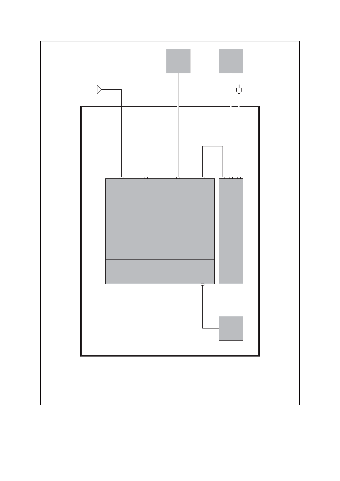
Figure 2.1 Block diagram of the main board of the radio body
28 General Description TM8100 Mobile Radio Service Manual
October 2003 © Tait Electronics Limited

Modules of main board
The control-head, main and digital boards, and the connectors on the
boards, are illustrated in Figure 1.6 of Section 1. Figure 2.1 is a block
diagram showing the main and digital boards and the circuit modules of
the main board. These modules are:
■ transmitter
■ receiver
■ frequency synthesizer
■ CODEC and audio circuitry
■ power supply
■ interface circuitry
Software plays a prominent role in the functioning of the TM8100 radio.
For describing the operation of the radio the software must be included
with the above modules. This is considered further below.
Operation of radio Figure 2.2 is a simplified block diagram of the transceiver architecture
showing the hardware modules integrated with the software modules.
The same DSP device includes the software that controls the transceiver
and the software constituting the digital-signal-processing blocks in
Figure 2.2. The operation of the radio is then best described with
reference to Figure 2.2 and with a division into the following three parts:
■ operation in receive mode
■ operation in transmit mode
■ operation of frequency synthesizer
Operational descriptions of these three parts are given in Subsection 2.3
to Subsection 2.5 respectively.
2.2 Operation of Control-head Circuitry
User interface In this subsection the operation of the control-head circuitry is
summarised. The standard control head provides a user interface
consisting of:
■ two-digit seven-segment LCD
■ up and down channel-selection keys
■ four programmable function keys
■ on/off push-button key
■ LED indicators
■ volume control
■ internal speaker
■ microphone connector
The microphone connector may also be used for the connection of a
handset or programming lead. If required, a concealed microphone may
be fitted inside the control head.
TM8100 Mobile Radio Service Manual General Description 29
October 2003 © Tait Electronics Limited

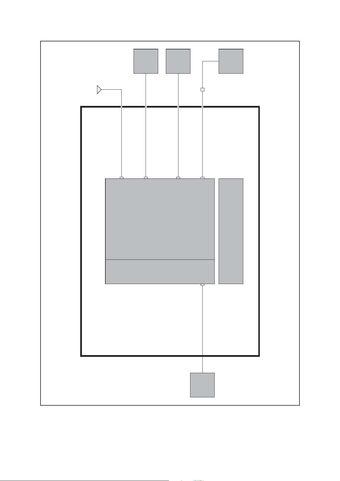
Figure 2.2 Architecture of the TM8100 transceiver
30 General Description TM8100 Mobile Radio Service Manual
October 2003 © Tait Electronics Limited

Connectors and circuit boards
There is an 18-way electrical interface between the control head and
radio body. The physical connection is via an 18-way loom. The control
head normally contains a single PCB assembly called the control-head
board. If a dynamic microphone is used or a concealed microphone
fitted, a small circuit board must be mounted on the control-head board.
The added board has the necessary amplification, filtering and switching
functions. The internal speaker is connected to the control-head board
via a lead with a mating connector so that it can be easily disconnected.
Control-head board The control-head board does not include a microprocessor. A
synchronous bi-directional serial interface provides communication of
key status, LCD and LED-indicator data between the radio body and the
control head. On the control-head board the serial data are converted to
or from parallel form by a number of shift registers for the keys and
indicators. For the LCD, the serial data are fed to a driver IC that
converts the serial data to a form suitable for the LCD itself. The keys
are scanned and the LCD and LED indicators updated approximately
every 50 ms.
2.3 Operation in Receive Mode
Receive path In this subsection the functioning of the radio in the receive mode is
described. As shown in Figure 2.2, the receive path exists in three
different domains:
■ hardware
■ custom logic
■ DSP
The front-end hardware amplifies and image-filters the received RF
spectrum, then down-converts the desired channel frequency to a first
intermediate frequency IF1 of 45.1 MHz (UHF) or 21.4 MHz (VHF)
where coarse channel filtering is performed. The first LO signal is
obtained from the frequency synthesizer. The output of the first IF is
then down-converted using an image-reject mixer to a low IF of 64 kHz.
Quadrature demodulator The LO for the image-reject mixer (quadrature demodulator) is
synthesized and uses the TCXO as a reference. This ensures good
centring of the IF filters and more consistent group-delay performance.
The quadrature demodulator device has an internal frequency division of
2 so the second LO operates at 2 x (IF1+ 64 kHz). The quadrature
output from this mixer is fed to a pair of AD Cs with high dynamic range
where it is oversampled at 256 kHz and fed to the custom logic device.
TM8100 Mobile Radio Service Manual General Description 31
October 2003 © Tait Electronics Limited

Custom logic
The remainder of the channel filtering is performed in custom logic.
Different filter shapes are possible to accommodate the various channel
spacings and data requirements. These filters provide the bulk of adjacent
channel selectivity for narrow-band operation. Each filter has a linear
phase response so that good group-delay performance for data is
achieved. The filters also decimate the sample rate down to 48 kHz.
Custom logic also performs demodulation, which is multiplexed along
with AGC and amplitude data and fed via a single synchronous serial port
to the DSP. The stream is demultiplexed and the demodulation data
stream processed further to meet audio requirements.
Automatic gain control The AGC is used to limit the maximum signal level applied to the image-
reject mixer and ADCs in order to meet the requirements for
intermodulation and selectivity performance. Hardware gain control is
performed by a variable gain amplifier within the quadrature
demodulator device driven by a 10-bit DAC. Information about the
signal level is obtained from the IQ data output stream from the ADCs.
The control loop is completed within custom logic. The AGC will
begin to reduce gain when the combined signal power of the wanted
signal and first adjacent channels is greater than about -70 dBm. In the
presence of a strong adjacent-channel signal it is therefore possible that
the AGC may start acting when the wanted signal is well below -70 dBm.
Noise squelch The noise squelch process resides in the DSP. The noise content above
and adjacent to the voice band is measured and compared with a preset
threshold. When a wanted signal is present, out-of-band noise content
is reduced and, if below the preset threshold, is indicated as a valid desired
signal.
Noise blanking Provision has been made for an optional noise blanker to remove
common sources of electrical interference such as vehicle ignition noise.
The noise blanker functions by sampling the RF input to the receiver for
impulse noise and momentarily disconnecting the first LO for the
duration of the impulse. The response time of the noise blanker is very
fast (tens of nanoseconds) and is quicker than the time taken for the RF
signal to pass through the front-end hardware, so that the LO is disabled
before the spike reaches the IF stage where it could cause crystal filter
ring. The noise blanker is fitted as standard for the VHF band.
Monitoring The lock-detect signal of the second LO synthesizer is monitored at least
every 100 ms. If the PLL fails to indicate lock within 10 ms of
programming, an error is reported by the control software. If an out-oflock condition occurs during run-time, then an audible indication will
be given and recovery repeatedly attempted.
32 General Description TM8100 Mobile Radio Service Manual
October 2003 © Tait Electronics Limited

Calibration
The following items within the receiver path are calibrated:
■ Front-end tuning
■ AGC
■ Noise squelch
■ RSSI
Information on the calibration of these items is given in the on-line help
facility of the calibration application.
Audio processing Raw demodulated data from the receiver is processed within the DSP.
The sample rate at this point is 48000 samples per second with signal
bandwidth limited only by the IF filtering. Scaling (dependent on the
bandwidth of the RF channel) and noise-peak limiting are then applied
to normalise the signal level for the remaining audio processing. The
sample rate is decimated to 8000 samples per second and then low-pass
filtered at 3 kHz, before being passed to the subaudible decoders and on
for further filtering in the main path. High-pass filtering is then applied
to remove the subaudible signalling and rumble from the audio signal.
The filter cut frequency is made higher when subaudible signalling is
expected compared to when it is not. This allows full low-frequency
audio response on non-subaudible channels.
Signal source for speaker The output of the high-pass filter is where in-band signalling decoders
obtain their input signal. The signal is then de-emphasised. The next
process in the chain is a multiplexer to select a signal source to feed the
main path to the speaker. The sources are as follows:
■ receive path
■ confidence-tone generator
■ transmit confidence side-tone
The confidence-tone generator is activated for such events as key-presses
or alarms; the level from this block is a fixed proportion (in the order of
-10 dB) relative to full scale in the receive path. Regarding the transmit
confidence side-tone, the output of the transmit signalling encoders can
be fed to the speaker to give the user confidence that the signalling
message is being sent; the level from this block is a fixed proportion (in
the order of -10 dB) relative to full scale in the receive path.
Combined audio and
side-tone signal
The combined audio and side-tone signal is converted to analogue form
by a 16-bit DAC, and then bandpass filtered by a switched cap filter
(100 Hz to 3.3 kHz) to remove alias components. This is followed by a
programmable-gain amplifier with 45 dB range that performs volume
control and muting. The volume control is logarithmic, with steps of
1.5 d B. Here, a side-tone from an options board can be summed in with
the receive audio.
TM8100 Mobile Radio Service Manual General Description 33
October 2003 © Tait Electronics Limited

Output to speakers
After side-tone summation the audio is fed to an audio power amplifier
and to the control head via a buffer amplifier. The output configuration
of the audio power amplifier is balanced and drives an internal speaker
and, optionally, an external speaker. The speaker loads are connected in
parallel rather than being switched. The power delivered to each speaker
is limited by its impedance. The internal speaker has 16-ohm impedance
whereas the external speaker can be as low as 4 ohms.
2.4 Operation in Transmit Mode
RF power amplifier
and switching
In this subsection the functioning of the radio in the transmit mode is
described. Refer to Figure 2.2. The RF power amplifier is a four-stage
line-up with approximately 42 dB of power gain. The output of the
frequency synthesizer is first buffered to reduce kick during power
ramping. The buffer output goes to a broad-band exciter IC that
produces approximately 200 mW output. This is followed by an
LDMOS driver producing up to 2 W output that is power-controlled.
The final stage consists of two parallel LDMOS devices producing
enough power to provide 25 W at the antenna.
Output of RF power amplifier The output of the RF power amplifier passes through a dual-directional
coupler, used for power control and monitoring, to the PIN switch. The
PIN switch toggles the antenna path between the receiver and
transmitter in receive and transmit modes respectively. Finally, the output
is low-pass-filtered to bring harmonic levels within specification.
Power control The steady-state power output of the transmitter is regulated using a
hardware control loop. The forward power output from the RF power
amplifier is sensed by the directional coupler and fed back to the power
control loop. The PA output power is controlled by varying driver gate
bias voltage that has a calibrated maximum limit to prevent overdrive.
The reference voltage for the control loop is supplied by a 13-bit DAC.
The system driving the DAC supplies the steady-state voltage for a given
power level as determined by factory calibration. The bandwidth of the
loop is high to ensure that it does limit the ramping slope and has
approximately 25 dB power control range. At low power settings the
final bias is reduced to improve efficiency and maintain power control
range.
Ramping Power ramp-up consists of two stages:
■ bias
■ power ramping
The timing between these two stages is critical to achieving the correct
overall wave shape in order to meet the specification for transient ACP.
34 General Description TM8100 Mobile Radio Service Manual
October 2003 © Tait Electronics Limited

Power
Bias
ramp
ll
Figure 2.3 Typical ramping waveforms
Power
ramp
Hi power
Lo power
Power
ramp
Bias
ramp
Time
Bias ramp-up
The steady-state final-stage bias level is supplied by an 8-bit DAC
programmed prior to ramp-up but held to zero by a switch on the DAC
output under the control of a
release by the
TX INHIBIT signal with the ramping shape being determined
TX INHIBIT signal. Bias ramp-up begins upon
by a low-pass filter. Owing to power leakage through the PA chain,
ramping the bias takes the PA output power from less than –10 dBm to
approximately 25 dB below steady-state power.
Power ramp-up The power ramp signal is supplied by a 13-bit DAC that is controlled by
custom logic. The ramp is generated using a look-up table in custom
logic memory that is played back at the correct rate to the DAC to
produce the desired waveform. The ramp-up and ramp-down
waveforms are produced by playing back the look-up table in forward
and reverse order respectively. For a given power level the look-up table
values are scaled by a steady-state power constant so that the ramp
waveform shape remains the same for all power levels. Typical ramping
waveforms are shown in Figure 2.3.
Inhibiting of transmitter The transmitter will be inhibited when any of the following conditions
exists:
■ frequency synthesizer out of lock
■ power supply voltage outside correct operating range
■ software inhibit present
The last-named signal would normally initiate the start of ramp-up.
TM8100 Mobile Radio Service Manual General Description 35
October 2003 © Tait Electronics Limited

Audio processing
The input to the transmitter path begins at the microphone input. There
are two microphone sources; a fist microphone connected to the control
head and an auxiliary microphone connected via the auxiliary or options
connector. Only electret-type microphones are supported. Support for
optional dynamic fist microphones is facilitated by a hardware amplifier
and filter in the control head.
Processing of
microphone signal
The CODEC performs microphone selection and pre-amplification.
The microphone amplifier consists of a by-passable amplifier with a fixed
gain of 20 dB followed by a programmable-gain amplifier with 0 to
22 dB gain giving up to 42 dB total control range. The amplified
microphone signal is converted to a digital stream by a 16-bit ADC and
then bandpass-filtered (0.1 to 3.2 kHz). The digital stream is transported
to the DSP for further processing.
Automatic level control The ALC follows, and is used to effectively increase dynamic range by
boosting the gain of the microphone pre-amplifier under quiet
conditions and reducing the gain under noisy acoustic conditions. The
ALC function resides in the DSP and controls the microphone preamplifier gain in the CODEC. The ALC has a fast-attack (about 10 ms)
and slow-decay (up to 2 s) characteristic. For the peak signal provided to
the DSP blocks that are next in the chain, this characteristic ensures that
the signal is regulated near full scale to maximise dynamic range.
Final processing
of audio signal
The audio is then high-pass filtered to remove any frequency
components that may exist in the subaudible signalling band and prevent
limiter overload. The encode signal for in-band signalling, if active, is
summed with the audio. Pre-emphasis is then applied, followed by a
limiter to remove transients that may have passed through the ALC. A
low-pass filter then removes unwanted limiter artefacts and also
interpolates the sample rate up to 48 kHz that is required for the interface
to the frequency synthesizer. At this point subaudible signalling, if active,
is summed with the audio. The final process is to scale the signal level
(and hence the deviation) to match the RF channel bandwidth and
compensate for subaudible signalling if added. The signal is then passed
to the frequency synthesizer where it is used as the modulation source.
36 General Description TM8100 Mobile Radio Service Manual
October 2003 © Tait Electronics Limited

2.5 Operation of Frequency Synthesizer
Control loops In this subsection the functioning of the frequency synthesizer is
described. Note that patents are pending for several aspects of the
synthesizer design. As may be seen from Figure 2.2, the frequency
synthesizer consists of two main parts:
■ RF PLL
■ FCL
The FCL generates a high-stability reference frequency that can be both
modulated and offset in fine resolution steps. The RF PLL has fastlocking capability but coarse frequency resolution. The FCL output is
the reference frequency input for the RF PLL. It is frequency-locked to
the TCXO, thereby acquiring the TCXO's frequency stability.
Modulation In dual-point modulation systems the modulation is applied to both the
frequency reference and the VCO in the RF PLL combining to produce
a flat modulation response down to DC. Reference modulation is
usually applied directly to the TCXO.
In the system employed in the TM8100 radio, the frequency reference is
composed of the 13 MHz TCXO and the FCL, which itself requires
dual-point modulation injection to allow modulation down to DC.
With another modulation point required in the RF PLL, this system
therefore requires triple-point modulation. The modulation cross-over
points occur at approximately 30 and 300 Hz as determined by the closed
loop bandwidths of the FCL and RF PLL respectively.
Frequency generation
and acquisition
The RF PLL is an integer-N type and has frequency resolution of
25 kHz. Higher resolution cannot be achieved owing to acquisitiontime requirements and so for any given frequency the error could
therefore be as high as ±12.5 kHz. This error is corrected by altering the
reference frequency to the RF PLL. The FCL supplies the reference
frequency and is able to adjust it up to ±300 ppm with better than
0.1 p pm resolution (equivalent to better than 50 Hz res o l ution at the RF
frequency). The FCL offset will usually be different for receive and
transmit.
Fast frequency settling Both the FCL and RF PLL employ frequency-acquisition speed-up
techniques to achieve fast frequency settling. The frequency-acquisition
process of the FCL and RF PLL is able to occur concurrently with
minimal loop interaction owing to the very large difference in frequency
step size between the loops.
TM8100 Mobile Radio Service Manual General Description 37
October 2003 © Tait Electronics Limited

Frequency-acquisition
of RF PLL
In the RF PLL the loop bandwidth is initially set high by increasing the
charge pump current and reducing time constants in the loop filter. As
a result settling to within 1 kHz of the final value occurs in under 3 ms.
In order to meet noise performance requirements the loop parameters
are then switched to reduce the loop bandwidth. There is a small
frequency kick as the loop bandwidth is reduced. Total settling time is
under 4.5 ms.
Frequency-acquisition
of FCL
The FCL utilises self-calibration techniques that enable it to rapidly settle
close to the final value while the loop is open. The loop is then closed
and settling to the final value occurs with an associated reduction in
noise. The total settling time is typically less than 4 ms.
Monitoring The lock detect signals of both the FCL and RF PLL are monitored by
the software. This is performed at least every 100 ms. If an out-of-lock
condition occurs during operation, then an audible indication will be
given and recovery repeatedly attempted.
Calibration The following items are calibrated in the frequency synthesizer:
■ Nominal frequency
■ Kvco
■ Kvcxo
■ VCO deviation
Calibration of the nominal frequency is achieved by adding a fixed offset
to the FCL nominal frequency; the TCXO frequency itself is not
adjusted. The items Kvco and Kvcxo are the control sensitivities of the
RF VCO (in MHz/V) and VCXO (in kHz/V) respectively. The latter
has temperature compensation.
38 General Description TM8100 Mobile Radio Service Manual
October 2003 © Tait Electronics Limited

3 Disassembly and Re-assembly of Radio
Introduction This section covers the disassembly and re-assembly procedures entailed
in level-1 repairs of the TM8100 radio. These procedures are:
■ detachment of control head
■ disassembly of control head
■ disassembly of radio body
■ re-assembly of radio body
■ re-assembly and attachment of control head
The procedures are detailed in Subsection 3.1 to Subsection 3.5
respectively. A brief outline of the overall level-1 repair procedure itself
is given below.
Important Observe anti-static precautions when servicing the
TM8100 radio in order to avoid damage caused by static
discharges.
Note The frequency ranges 156.8 MHz ± 375 kHz,
243 MHz ± 5 kHz, and 406.0 to 406.1 MHz are reserved
worldwide for use by distress beacons. Do not program
transmitters to operate in any of these frequency bands.
Outline of level-1
repair procedure
For level-1 repairs first determine whether the control head or radio
body is faulty. Do so by exchanging the control head for a spare control
head. (Detach the control head as described in Subsection 3.1.) If the
fault is rectified, the original control head is faulty; if not, the radio body
is faulty. In the case of a faulty two-digit control head, also exchange the
control-head loom for a spare loom. If the fault is rectified, the original
loom is faulty; if not, the control head itself is faulty. After thus isolating
the fault, repair a faulty control head and a faulty radio body as indicated
in the following two paragraphs respectively.
Control head is faulty If the control head is faulty, first inspect the control head for obvious
damage as described in Subsection 3.1. Replace any damaged part or
assembly; this might require removing the control-head board as
described in Subsection 3.2. If there is no obvious damage, replace the
control-head board. In either case, re-assemble the radio as described in
Subsection 3.5, and subject the radio to a final test.
TM8100 Mobile Radio Service Manual Disassembly and Re-assembly of Radio 39
October 2003 © Tait Electronics Limited

UNDERSIDE OF CHASSIS
RADIO
BODY
LEVER
POINT
CONTROL HEAD
INDICATION OF
LEVER POINT
DETAILS OF
LEVER POINT
bb
Figure 3.1 Lever points for detaching the control head from the radio body
Radio body is faulty
If the radio body is faulty, the main-board assembly will need
replacement. However, the control head should also be inspected for
damage as described above, and any damage rectified. Next, open the
radio body, remove the main-board assembly, and obtain a replacement
assembly. The procedure is described in Subsection 3.3 and includes
inspecting the radio body and rectifying any damage. Then re-assemble
the radio body as described in Subsection 3.4 and re-attach the control
head. If necessary, recalibrate the radio. Finally, reprogram and test the
radio.
40 Disassembly and Re-assembly of Radio TM8100 Mobile Radio Service Manual
October 2003 © Tait Electronics Limited

3.1 Detachment of Control Head
Detach control head Whether the control head or the radio body is faulty, the control head
needs to be detached from the radio body. Do so as follows:
1. Note which way up the control head is attached to the radio body.
The control head may be oriented with the underside of the radio
body either at the top or bottom. The configuration depends on
the Customer’s installation, and the radio will need to be returned
to the Customer with the same configuration.
2. Disconnect the radio from any test equipment or power supply.
3. Note the two points where the control head should be levered off
the radio body. As shown in Figure 3.1, these points are indicated
by dot-dash-dot marks on the underside of the radio body. The
lever point is between the rubber seal and the front panel of the
control head. (The seal is called the control-head seal.)
4. At each of the above lever points, insert the blade of a medium-
sized (about 5 mm) flat-bladed screwdriver and lever off the
control head.
5. After detaching the control head, disconnect the control-head
loom at the connector on the radio body. Refer to Figure 3.2.
6. Inspect the control head and loom as described below.
TM8100 Mobile Radio Service Manual Disassembly and Re-assembly of Radio 41
October 2003 © Tait Electronics Limited

CONTROL-HEAD LOOM
CONTROL-HEAD
SEAL
RADIO BODY
SEAL
SEAL LIPS
CONTROL HEAD
FRONT FACE OF RADIO BODY
df-cm-dwls
Figure 3.2 Details of the seal between the radio body and control head
CONTROL-HEAD SEAL
DETAILS OF
42 Disassembly and Re-assembly of Radio TM8100 Mobile Radio Service Manual
October 2003 © Tait Electronics Limited

Inspect mechanical parts
Regardless of the reason for detaching the control head, it is advisable to
inspect the mechanical parts for damage. Check for and rectify any
damage as follows:
1. Inspect the control-head loom. If the loom has obvious physical
damage, replace it with a spare loom from Spares kit 1. The
product code and contents of the kit are listed in Subsection 3.2.
2. Inspect the control-head seal. Refer to Figure 3.2, which shows
a cross-section of the seal. Check for any sign of deformation, cuts
or tears. Pay particular attention to the two lips of the seal.
3. If the seal is damaged, replace it with a spare seal from Spares kit
7. This kit contains a set of these seals.
4. Inspect the control head for signs of damage. Check for cracked,
broken or burnt parts. In a two-digit-display control head the
parts to inspect are the volume-control knob, keypad, lens, spaceframe, speaker and, if fitted, concealed microphone. In a blank
control head inspect the programming connector and attached
loom.
5. If the inspection in Step 4 reveals no damage, continue with the
repair of the radio. If there is damage in a two-digit-display
control head, disassemble the control head and replace the
damaged part or assembly as described in the next subsection. If
there is damage in a blank control head, replace the complete
control head; for the relevant product code refer to
Subsection 1.5.
TM8100 Mobile Radio Service Manual Disassembly and Re-assembly of Radio 43
October 2003 © Tait Electronics Limited

POSITION OF CIRCUIT
BOARD FOR OPTIONAL
MICROPHONES
BOARD
CLIP 3
CONNECTORS FOR
OPTIONAL BOARD
CONNECTOR
CONTROL-HEAD
CONCEALED MICROPHONE
(IF FITTED)
CONTROL-HEAD
SCREW 3 GUIDE 4SCREW 2GUIDE 1GUIDE 2
PADS FOR LEADS TO
CONCEALED MICROPHONE
SPEAKER
SCREW 1 CLIP 1 CLIP 2
GUIDE 3
CONNECTOR
SPEAKER
Figure 3.3 Plan view of the control head showing the control-head board
44 Disassembly and Re-assembly of Radio TM8100 Mobile Radio Service Manual
October 2003 © Tait Electronics Limited
bb-dwls

3.2 Disassembly of Control Head
Introduction This subsection covers the disassembly of the two-digit-display control
head and the replacement of a damaged part or assembly. There are two
stages in the disassembly procedure:
■ remove control head board
■ replace damaged part or assembly
For the latter task the control-head board must first be removed. A
separate circuit board for a concealed or dynamic microphone might or
might not be mounted on the control-head board.
Remove control-head board The procedure for removing the control-head board is as follows. Refer
to Figure 3.3.
1. Pull off the knob from the volume-control potentiometer. Do not
use any tools to do so as this might cause damage.
2. If a circuit board for a concealed or dynamic microphone is fitted,
unplug it from the control-head board.
3. If a concealed microphone is fitted, unsolder the microphone leads
from the control-head board. The leads are soldered to pads on
the board as shown in Figure 3.3.
4. Note whether the speaker leads are connected to the control-head
board. If so, disconnect the leads. The radio will need to be
returned to the Customer in its original state.
5. Remove the screws securing the control-head board. The order
of removal is immaterial. The screws are labelled screw 1 to screw
3 in Figure 3.3; these numbers are also inscribed on the PCB. The
control-head board is now held down only by the clips labelled
clip 1 to clip 3 in Figure 3.3.
6. Pull upwards on the edge of the control-head board adjacent to
the speaker. At the same time push clip 1 and clip 2 by hand away
from the board. The board will lift up slightly.
7. Push clip 3 away from the control-head board while
simultaneously pressing on the shaft of the volume-control
potentiometer. The board will be freed from the space-frame.
Remove the board.
8. If the earlier inspections have not revealed any damaged parts,
continue with the repair of the radio. If there is damage, continue
with the disassembly of the control head and rectify the damage as
described below.
TM8100 Mobile Radio Service Manual Disassembly and Re-assembly of Radio 45
October 2003 © Tait Electronics Limited

Table 3.1 Contents of TMAA22-01 Spares kit 1 — parts of standard control head less control-head board
IPN Description Quantity
— Front-panel assembly (see below for constituent parts) 1
311-01054-xx Knob for volume-control potentiometer 1
— Control-head-loom assembly (see below for constituent parts) 1
346-10030-08 3 x 8 PT screw for control-head board 3
Parts of front-panel assembly
316-06786-xx Front panel 1
312-01095-xx Lens with Tait logo 1
365-01717-xx Label for TM8115 1
209-00011-xx Elastomeric strip 2
319-30073-xx Space-frame 1
008-00031-xx LCD 1
252-00011-xx Speaker 1
307-01024-xx Speaker membrane 1
311-03114-xx Keypad 1
262-00003-xx Short light pipe 2
262-00004-xx Long light pipe 2
Parts of control-head-loom assembly
219-02882-xx Control-head loom 1
240-00021-41 Female-female adaptor for control-head connector 1
Note
The characters xx in an IPN stand for the issue number. Items in the spares kit will always be the latest issue at the
time the spares kit is produced.
46 Disassembly and Re-assembly of Radio TM8100 Mobile Radio Service Manual
October 2003 © Tait Electronics Limited

Front-panel assembly
and Spares kit 1
The assembly remaining after the removal of the control-head board is
called the front-panel assembly. A complete front-panel assembly is
included in Spares kit 1; the other parts in the kit are a control-head
loom, screws for the control-head board, and a volume-control knob.
The contents of the kit, including the parts of the front-panel assembly,
are listed in Table 3.1. The IPN of each spare part is given but, if
applicable, not
the issue number within the IPN. The latest issue of a
particular part is always supplied.
Repair of frontpanel assembly
There are two methods of repairing a damaged front-panel assembly:
■ replace complete front-panel assembly
■ replace damaged parts of front-panel assembly
Generally either method may be used. However, the latter method must
be used if a concealed microphone is fitted or custom labels have been
added to the front panel. The two methods are described separately
below:
Replace front-panel assembly To replace the complete front-panel assembly, discard the damaged
assembly and obtain a replacement assembly from Spares kit 1. Leave the
spare control-head loom, the screws, and the volume-control knob in the
kit. Continue with the repair of the radio. Later in the repair procedure
the control-head board will be fitted to the new front-panel assembly and
the complete control head will be assembled.
TM8100 Mobile Radio Service Manual Disassembly and Re-assembly of Radio 47
October 2003 © Tait Electronics Limited

APERTURE FOR SHAFT
OF VOLUME-CONTROL
ELASTOMERIC STRIPS
POTENTIOMETER
LCD
APERTURE FOR
MICROPHONE
CONNECTOR
KEYPAD
LIGHT PIPES FOR
STATUS LEDs
CONCEALED MICROPHONE
(IF FITTED)
SPACE-FRAME
CLIP 5 CLIP 3 CLIP 1
SPEAKER
CLIP 6 CLIP 4 CLIP 2
bb-dwls
Figure 3.4 Plan view of the control head with the control-head board removed
48 Disassembly and Re-assembly of Radio TM8100 Mobile Radio Service Manual
October 2003 © Tait Electronics Limited

Replace damaged parts —
disassembly task
To replace a damaged part, first disassemble the damaged front-panel
assembly as well as a spare assembly from Spares kit 1. Proceed as follows.
Refer to Figure 3.4.
1. Note the clips on the space-frame labelled clip 1 to clip 6 in
Figure 3.4. These clips need to be released to remove the spaceframe.
2. While pulling upwards on the space-frame at the corner where the
microphone connector is situated, release the clips in the order:
clips 1 and 2, 3 and 4, and then 5 and 6. To release each clip use
a medium-sized (about 5 mm) flat-bladed screwdriver to lever the
clip out of its recess. Pulling on the space-frame helps release the
clips.
3. Pull the space-frame out when all six clips have been released.
4. Remove the elastomeric strips, speaker, LCD, keypad and, if
fitted, concealed microphone.
Replace damaged parts —
replacement task
Replace any of the following parts that inspection has shown to be
damaged. Refer to the accessories manual regarding the replacement of
a concealed microphone that has been damaged.
■ elastomeric strips
■ space-frame
■ speaker
■ keypad
■ LCD
■ front panel
Obtain replacement parts from the disassembled spare front-panel
assembly. Discard the damaged parts and return unused spare parts to
Spares kit 1. Note that spare front panels include the speaker membrane,
lens and branding label; the LED light pipes are moulded into the panel.
If any part of the front panel is damaged, including the membrane, lens
and light pipes, replace the complete panel.
TM8100 Mobile Radio Service Manual Disassembly and Re-assembly of Radio 49
October 2003 © Tait Electronics Limited

LEVER POINT
DETAILS OF
LEVER POINT
bbbb
Figure 3.5 Lever points for removing the cover of the radio body
LOWER
SCREW
BOSS
UPPER
SCREW
BOSS
50 Disassembly and Re-assembly of Radio TM8100 Mobile Radio Service Manual
October 2003 © Tait Electronics Limited

3.3 Disassembly of Radio Body
Introduction This subsection covers the disassembly of the radio body. There are two
stages in the disassembly procedure:
■ open radio body
■ remove main-board assembly
The control head need not be detached before the radio body is opened,
but it must be detached before the main-board assembly can be removed.
Open radio body The first stage in disassembling the radio body is to remove the cover and
lid. In the process it is advisable to inspect and, if necessary, replace the
main seal in the lid. The procedure is included in the disassembly
instructions:
1. Note the two screw bosses on each side of the chassis. The cover
clips to the underside of each upper boss. Also note the two points
where the cover should be levered off the radio body. As shown
in Figure 3.5, each lever point is a slot above the lower screw boss.
2. Insert the blade of a small (about 3 mm) flat-bladed screwdriver in
each of the above slots in turn. In each case push the screwdriver
under the cover towards the upper screw boss. This will release
the cover from the upper boss. Remove the cover.
3. Use a Torx T20 screwdriver to remove the four screws securing
the lid of the radio body. The screws are shown in Figure 3.6.
4. Carefully remove the lid. If an options board is fitted, there will
be an options loom connecting the main board in the chassis and
the options board in the lid. If this is the case, place the lid next
to the chassis as shown in Figure 3.7 and disconnect the loom.
5. Inspect the main seal in the lid for any sign of deformation, cuts
or tears. Refer to Figure 3.7. If the seal is damaged, replace it
with a spare seal from Spares kit 2. The contents of the kit are
listed in Table 3.2. The IPN of each spare part is given but, if
applicable, not
the issue number within the IPN. The latest issue
of a particular part is always supplied.
6. Inspect the radio body for damage to the cover and the seal for the
RF connector, and for loss of the bungs for the auxiliary and
external options connectors. Replace any lost or damaged part
with a spare part from Spares kit 2.
TM8100 Mobile Radio Service Manual Disassembly and Re-assembly of Radio 51
October 2003 © Tait Electronics Limited

bb
Figure 3.6 The four screws that secure the lid to the chassis of the radio body
52 Disassembly and Re-assembly of Radio TM8100 Mobile Radio Service Manual
October 2003 © Tait Electronics Limited

SLOT IN HEAT-TRANSFER
BLOCK FOR SCREWDRIVER
INTERNAL OPTIONS CONNECTOR
OPTIONS LOOM
MAIN SEAL
INTERNAL
OPTIONS
BOARD
LID
MAIN SEAL
MAIN BOARD
CHASSIS
Figure 3.7 Illustration of the lid removed from the chassis of the radio body, with an options board
installed in the lid
TM8100 Mobile Radio Service Manual Disassembly and Re-assembly of Radio 53
October 2003 © Tait Electronics Limited
bb-dwls

PLAN VIEW
SCREW 1
DIGITAL BOARD
SCREW 2 SCREW 3 SCREW 4 SCREW 5
PAD TOP
CAN
MAIN
BOARD
HEAT-TRANSFER BLOCK
REAR VIEW
BUNG FOR
AUXILIARY CONNECTOR
bb-dwls
SCREW 6 SCREW 7
Figure 3.8 Illustration of the chassis showing the screws that secure the main-board assembly
RF CONNECTOR
SEAL FOR
54 Disassembly and Re-assembly of Radio TM8100 Mobile Radio Service Manual
October 2003 © Tait Electronics Limited

Remove main-board assembly
The second stage in disassembling the radio body is to remove the mainboard assembly.
1. Remove the bung (if fitted) covering the auxiliary connector.
2. Remove the rubber seal around the RF connector — preferably
by hand. If necessary, however, lever up the seal by inserting the
blade of a small (about 3 mm) flat-bladed screwdriver in the gap
beneath the seal. See Figure 3.8. Do not damage the seal with
the screwdriver.
3. Note the five interior screws securing the main-board assembly;
these are labelled screw 1 to screw 5 in Figure 3.8. Use a Torx
T10 screwdriver to remove the screws. The order of removal is
immaterial, but good practice would be to follow the order from
screw 1 to screw 5.
4. Note the two exterior screws securing the main-board assembly;
these are labelled screw 6 and screw 7 in Figure 3.8. Use a Torx
T20 screwdriver to remove the screws.
5. The main-board assembly is now free of the chassis. Note the slot
in the heat-transfer block shown in Figure 3.7. Insert the blade of
a small (about 3 to 5 mm) flat-bladed screwdriver in the slot. Tilt
the screwdriver to lever up the front edge of the circuit board.
Grip the edge of the board and pull out the assembly, but avoid the
thermal paste on the heat-transfer block. The area coated with
thermal paste is shown in Figure 3.9.
TM8100 Mobile Radio Service Manual Disassembly and Re-assembly of Radio 55
October 2003 © Tait Electronics Limited

HEAT-TRANSFER BLOCK
AUXILIARY
CONNECTOR
AND SEAL
POWER
CONNECTOR
AND SEAL
DIGITAL BOARD
INTERNAL OPTIONS
CONNECTOR
MAIN BOARD
bb-dwls
Figure 3.9 The main-board assembly
RF CONNECTORTHERMAL PASTE
56 Disassembly and Re-assembly of Radio TM8100 Mobile Radio Service Manual
October 2003 © Tait Electronics Limited

Table 3.2 Contents of TMAA22-02 Spares kit 2 — mechanical parts of radio body
IPN Description Quantity
— Cover assembly (see below for constituent parts) 1
349-02067-xx M4 x 16 screw for lid of radio body 4
362-01115-xx Control-head seal 1
362-01109-xx Main seal in lid 1
302-50000-xx Bung for external options connector 1
302-50001-xx Bung for auxiliary connector 1
362-01113-xx Seal for RF connector 1
349-02067-xx External M4 x 16 screw for main-board assembly 2
349-02066-xx Internal M3 x 10 screw for main-board assembly 5
362-01114-xx Rubber seal for power connector 1
354-01043-xx Lock-nut for auxiliary connector 1 pair
362-01112-xx Outer foam seal for auxiliary connector 1
362-01110-xx Inner foam seal for auxiliary connector 1
Parts of cover assembly
303-23166-xx Cover 1
365-01712-xx Label for cover 1
Note
The characters xx in an IPN stand for the issue number. Items in the spares kit will always be the latest issue at the
time the spares kit is produced.
TM8100 Mobile Radio Service Manual Disassembly and Re-assembly of Radio 57
October 2003 © Tait Electronics Limited

3.4 Re-assembly of Radio Body
Introduction There are two stages in the re-assembly of the radio body:
■ install main-board assembly
■ close radio body
The procedures for the two stages are given separately below. The torque
values for the screws involved are summarised in Table 3.3.
Install main-board assembly
— apply thermal paste
If the main-board assembly needs to be installed, proceed as follows. The
first task is to replenish the thermal paste on the heat-transfer block:
1. Thermal paste is required on the area of the heat-transfer block
shown in Figure 3.9. This area constitutes the contact area
between the main-board assembly and the chassis.
2. Inspect the area on the heat-transfer block requiring thermal paste,
as well as the corresponding area on the chassis. If the residual
paste has been contaminated with dirt, clean off the paste.
3. Obtain 0.1 cm
3
of thermal paste. Use Dow Corning 340 silicone
heat-sink compound (IPN 937-00000-55) or the equivalent.
4. Use a stiff brush to apply the paste in a thin film to the required
area on the heat-transfer block. Ensure that no bristles from the
brush come loose and remain embedded in the paste. The paste
needs to be completely free of contaminants.
Table 3.3 Summary of the torque values for the screws used in TM8100 mobile radios
Description of screws Drive type Quantity Torque (N·m) Torque (lbf·in)
Screws for control-head board Torx T10 3 0.56 5
Screws for lid of radio body Torx T20 4 2.5 22
External screws for main-board assembly Torx T20 2 2.5 22
Internal screws for main-board assembly Torx T10 5 1.9 17
58 Disassembly and Re-assembly of Radio TM8100 Mobile Radio Service Manual
October 2003 © Tait Electronics Limited

Important Ensure that the two external screws securing the main-
board assembly are properly tightened; otherwise the
radio will overheat and might be damaged.
Install main-board assembly
— secure assembly in chassis
Complete the installation of the main-board assembly by securing the
assembly in the chassis:
1. Place the main-board assembly in position in the chassis.
2. Screw in the two external screws by hand as far as possible. The
screws are labelled screw 6 and screw 7 in Figure 3.8. Ensure that
the screws start easily and are not cross-threaded.
3. Identify the diagonal edge of the PAD TOP can. The can is
shown in Figure 3.8.
4. While pressing down firmly on the diagonal edge of the PAD
TOP can, use a Torx T20 torque-driver to tighten the screws to
2.5 Nm (22 lbfin). (If the screws are not tightened properly, the
radio will overheat.) The reason for pressing down on the can is
to ensure that the circuit board is seated correctly on the bosses for
the five internal screws.
5. Clean off any excess thermal paste on the heat-transfer block.
6. Screw in the five internal screws by hand. The screws are labelled
screw 1 to screw 5 in Figure 3.8. Ensure that the screws start easily
and are not cross-threaded. Then use a Torx T10 torque-driver to
tighten the screws to 1.9 Nm (17 lbfin).
7. Fit the rubber seal for the RF connector; first fit the upper part of
the seal and then press down around the sides of the seal to the
bottom. Ensure that the seal is properly seated around its entire
periphery.
8. In most radios a bung will have been supplied for the auxiliary
connector. In such cases the bung must be fitted again on reassembly to ensure that the radio is sealed. In fitting the bung,
ensure that it is not upside down and that it is properly seated.
TM8100 Mobile Radio Service Manual Disassembly and Re-assembly of Radio 59
October 2003 © Tait Electronics Limited

Close radio body
Secure the lid and cover of the radio body as follows:
1. If an options board is installed in the lid of the radio body,
reconnect the options loom to the internal options connector on
the main board. This is best done with the lid placed next to the
chassis as shown in Figure 3.7.
2. Place the lid in position on the chassis. Ensure that the main seal
in the lid is properly seated.
3. Screw in by hand the four screws that secure the lid. Ensure that
the screws start easily and are not cross-threaded. Then use a Torx
T20 torque-driver to tighten the screws to 2.5 Nm (22 lbfin).
4. Fit the cover of the radio body.
60 Disassembly and Re-assembly of Radio TM8100 Mobile Radio Service Manual
October 2003 © Tait Electronics Limited

3.5 Re-assembly and Attachment of Control Head
Introduction There are at most three stages in the re-assembly and attachment of the
control head. The first two stages concern the two-digit-display control
head only, not the blank control head. The three stages are:
■ re-assemble mechanical parts of control head
■ re-install control-head board
■ re-attach control head
The procedures for the three stages are given separately below. The first
stage is required only if the control head has been completely
disassembled. The second stage is required if the control-head board has
been removed; this stage includes the fitting, if applicable, of the circuit
board for optional concealed and dynamic microphones. The torque
values for the screws involved are included in Table 3.3.
Re-assemble mechanical
parts of control head
If the two-digit-display control head has been completely disassembled,
re-assemble the mechanical parts as follows:
1. Ensure that the LCD is free of dirt and fingerprints. Wipe the
LCD with a soft lens-cleaning cloth. If necessary, clean the LCD
using isopropyl alcohol.
2. Place the LCD in its recess in the cover as shown in Figure 3.4.
There is only one correct orientation: the small protrusion on the
edge of the LCD must be adjacent to the wall of the front panel.
3. Place the keypad in position on the floor of the front panel.
4. Place the speaker in position and, if included, the concealed
microphone.
5. Place the space-frame in position. Ensure that the leads from the
speaker and, if fitted, the concealed microphone do not foul the
frame. The leads will need to be connected to the top of the
control-head board when the board is installed.
6. Press down on the space-frame until all six clips on the frame snap
into place in their recesses.
7. Ensure that the conductors along the edges of the two elastomeric
strips are clean. Wipe the strips with a soft lens-cleaning cloth. If
necessary, clean the strips using isopropyl alcohol.
8. Insert the two elastomeric strips in their slots in the space-frame.
TM8100 Mobile Radio Service Manual Disassembly and Re-assembly of Radio 61
October 2003 © Tait Electronics Limited

Re-install control-head board
Re-install the control-head board and, if included, the optional
microphone board as follows. The torque values for the screws securing
the control-head board are included in Table 3.3.
1. Place the control-head board in position on the space-frame.
Ensure that the board fits inside the four guides on the frame. The
guides are labelled guide 1 to guide 4 in Figure 3.3.
2. Press straight down on the control-head board until the three clips
on the space-frame snap into position against the board. The clips
are labelled clip 1 to clip 3 in Figure 3.3. It is important not
to
press d own on t he c ircu i t b o ard a t an ang le. To do so m igh t di s tor t
the elastomeric strips, causing failure in the operation of the LCD.
3. Screw in by hand the three screws that secure the control-head
board. The screws are labelled screw 1 to screw 3 in Figure 3.3.
Ensure that the screws start easily and are not cross-threaded.
Then, beginning with screw 1, use a Torx T10 torque-driver to
tighten the screws to 0.6 Nm (5 lbfin).
4. If an optional microphone board is included, attach the board to
the control-head board. The two sockets on the former connect
to corresponding plugs on the latter.
5. If a concealed microphone is fitted, solder the leads from the
microphone to the relevant pads on the control-head board. The
pads are shown in Figure 3.3.
6. If the speaker leads were originally connected to the control-head
board, as noted in Subsection 3.2, then reconnect the leads.
Orient the plug on the leads so that the ridge on one side of the
plug is uppermost.
7. Push the knob onto the shaft of the volume-control
potentiometer. Ensure that the knob turns freely.
Re-attach control head Re-attach the control head to the radio body as follows. The procedure
applies to both the two-digit-display control head and the blank control
head.
1. Orient the control head with respect to the radio body as noted in
Subsection 3.1.
2. Reconnect the control-head loom to the connector on the radio
body. Refer to Figure 3.2.
3. Align the control head with the inner face of the radio body.
Ensure that the control-head loom folds properly into the space
between the control head and the radio body.
4. Press the control head against the radio body until it clips into
position. Ensure that the seal is not damaged in the process.
5. Continue with the servicing procedure.
62 Disassembly and Re-assembly of Radio TM8100 Mobile Radio Service Manual
October 2003 © Tait Electronics Limited
 Loading...