

Page 1

TMAA12 / T2009 Power Supply User’s Guide
for Tait TM8000 and T2000 Mobile Radios
www.taitworld.com
Page 2

TMAA12 kit for TM8000 Installation (page 6)
T2009 power supply
mains cable
TM8000 power cable
microphone clip
2 screws
4 thumb screws
U-bracket
T2009 kit for T2000 Installation (page 10)
mains cable
radio cabinet
T2009 power supply
4 nuts
4 washers
microphone clip
2 screws
T2000 power cable
Page 3

Contents
Important Safety Information ...........................................................2
User Information ..............................................................................4
Installing a TM8000 .........................................................................6
Installing a T2000 ..........................................................................10
Fault Finding Information ...............................................................16
Electrical Specifications ..................................................................17
Updating this Guide
In the interests of improving the performance, reliability or servicing of the equipment, Tait
Electronics Ltd. reserves the right to update either the equipment or this user's guide, without prior notice.
Contents 1
Page 4

Important Safety
Information
Please read these warnings before using your T2009 power
supply.
Warning: Safe Operation
To reduce the risk of fire or electric shock, please adhere to
these warnings:
■ Moisture: Do not expose this appliance to rain or moisture.
■ Cleaning: Unplug the power supply from the mains power
outlet before cleaning. Switching it off will not reduce this
risk.
■ Ventilation: Place the power supply in an area that will
allow air to flow freely around the unit. This will prevent the
power supply and mobile radio from overheating. Do not
block or obstruct any of the ventilation openings on the
unit.
Warning: Electrical Connections
To reduce the risk of fire or electric shock, please adhere to
these warnings:
■ Do not operate two or more units in parallel.
■ Your power supply should be properly connected and
grounded. Use the provided AC power cable to connect it to
a mains power outlet that is properly installed and
grounded, in accordance with all local codes and ordinances. If the power supply cord is damaged, it must be
replaced with the same type to comply with safety requirements.
■ Never alter the provided AC cable or plug. If the plug does
not fit into the outlet, have a proper outlet installed by a
certified electrician.
■ Use an extension cord only when absolutely necessary. The
extension cord must have the same voltage and power rating as the original power supply plug. Make sure that the
2 Important Safety Information
Page 5

pins on the plug are of the same number, size and shape as
those of the original power supply plug.
■ Do not connect a backup battery directly to the power sup-
ply.
■ Do not use the power supply to directly charge a battery.
Warning: Servicing
This power supply should be serviced by a qualified servicing
technician. Incorrect assembly may result in electric shock or
fire. We recommended that you return your power supply to a
qualified Tait Electronics Ltd. dealer for any service or repair.
Warning: High Voltage Levels
Some of the components inside the T2009 operate at voltage
levels that may be lethal.
Important Safety Information 3
Page 6

User Information
The T2009 power supply enables you to use your Tait T2000 or
Tait TM8000 mobile radio as a desktop radio.
The T2009 is a switched mode power supply. It converts mains
input voltage to regulated 13.8VDC, using pulse width modulation (PWM) control.
The T2009 power supply is protected against short circuits, as
well as over current and over voltage conditions.
Check the Mains Supply Voltage
Before you plug in and turn on your power supply the first time,
please check the mains supply voltage.
The voltage rating of the T2009 is printed on a label on the
bottom of the supply. Verify that it corresponds with your local
mains supply voltage (i.e. 120 VAC or 230 VAC).
The variations in mains supply voltage under which the T2009
can operate, are listed in the “Electrical Specifications” table on
page 17.
Turning the Power Supply on
The T2009 has an illuminated on/off switch, marked “I” for on
and “O” for off. Turn the power supply on by pressing the “I”
side of the switch. The indicator inside the switch will illuminate.
Note: If the T2009 does not turn on, refer to “Fault Finding
Information” on page 16.
Turning the Power Supply Off
Before you turn the power supply off, turn the radio off as
described in the user documentation for the radio.
To turn the power supply off, press the “O” side of the power
switch.
4 User Information
Page 7

Cooling
The T2009 is cooled by convection cooling (normal airflow
around the power supply).
Place the unit in a well ventilated and cool area. Do not block
the ventilation openings on the sides, back or top of the unit.
Using the Microphone
Your radio can be programmed to activate or deactivate scanning or monitoring through the “hookswitch” feature. For more
information, refer to your radio’s user and programming documentation.
Battery Charging
The T2009 should not be used as a battery charger.
Servicing
By following the procedures in this manual, and by exercising
normal care, your T2009 will give you trouble-free service for
many years.
However, when required, servicing should be carried out by a
qualified service technician. Within the warranty period, servicing must be carried out by your Tait dealer.
Installation Information
Caution: Install the T2009 indoors. It is not designed for
operation out-of-doors or in wet environments.
The installation of the T2009 and mobile radio is critical to its
performance. Tait authorised dealers are able to offer a prompt,
professional installation service.
The mobile radio can be operated at a distance from the T2009,
or it can be mounted on top of the T2009.
Note: When using a Tait radio in a desk top or despatcher
configuration (i.e. in conjunction with the T2009 at a fixed location), check the maximum legal transmit output power as
defined by the local regulatory authority (often in the range of 1
to 5W). Exceeding this output power may result in prosecution.
User Information 5
Page 8

Installing a TM8000
The parts required to install a TM8000 radio on the T2009 are
shown on the inside front cover of this user’s guide.
Quick Reference
Mount the U-bracket on the T2009.
❏
Mount the radio in its U-bracket.
❏
❏
Mount the microphone clip.
Connect the power supply to the radio.
❏
❏
Connect the antenna to the radio.
❏
Turn on the radio and check its operation.
Determine the U-bracket’s position
The recommended position for the U-bracket is on the top
surface of the T2009, 60mm from the front edge.
60mm
Clean the top surface of the T2009
1. Use a solution of isopropanol and water (50/50) to remove
any oil or dirt from the top surface of the T2009.
Caution: Be extremely careful when handling solvents. Follow
the manufacturer’s precautions and directions for use.
6 Installing a TM8000
Page 9

Mount the U-bracket on the T2009
To ensure maximum bond strength, the temperature of both the
T2009 and the U-bracket should be above 20°C (68°F).
U-bracket
adhesive surfaces
remove protective liner1
1. Remove the liners that protect the adhesive surfaces on the
2. Position the U-bracket on the T2009 and press down firmly
3. Maximum bond strength will be achieved within 72 hours.
2
press U-bracket down firmly
bottom of the U-bracket.
along the whole length of the U-bracket
Installing a TM8000 7
Page 10

Mount the TM8000 Radio
thumb screws
U-bracket
1. Position the radio in the U-bracket so that the holes in the
U-bracket line up with the holes in the radio chassis.
2. Fasten the radio with the four thumb screws.
3. Adjust the radio in the U-bracket for best viewing angle and
tighten the thumb screws.
Mount the Microphone clip
microphone clip
U-bracket
mounting holes
1. Mount the microphone clip to the side of the U-bracket, as
shown below, with the supplied screws.
8 Installing a TM8000
Page 11

Connect the Radio and the Power Supply
Note: The red wire of the power cable is positive.
supply wires
TM8000 power connector
1. Make sure that the radio and the T2009 are both turned off.
Unplug the T2009 from the mains supply outlet.
2. Connect the power cable’s positive (red) wire and negative
(black) wire to the positive and negative terminals on the
back of the T2009.
3. Plug the power cable into the power socket on the back of
the radio.
To Complete the Installation
1. If an external speaker is required, connect it as described in
the installation documentation for the speaker.
2. Make sure that the radio is switched off, as described in the
user documentation for the radio.
3. Plug the power supply into the mains supply outlet and
4. Make sure that the power indicator in the switch illumi-
5. Connect the radio’s antenna.
6. Turn on the radio and make sure that it operates satisfacto-
switch it on.
nates. If the indicator fails to light up, check the connection
and mains power outlet. Turn to“Fault Finding Information”
on page 16 if the problem persists.
rily, as described in the user documentation for the radio.
Installing a TM8000 9
Page 12
Installing a T2000
The parts required to install a T2000 radio on the T2009 are
shown on the inside front cover of this user’s guide.
Quick Reference
Install the radio inside the radio cabinet.
❏
Mount the radio cabinet on the T2009.
❏
❏
Connect the power supply connector to the radio.
Mount the microphone clip.
❏
❏
Connect the power supply to the radio.
❏
Turn on the radio and check its operation.
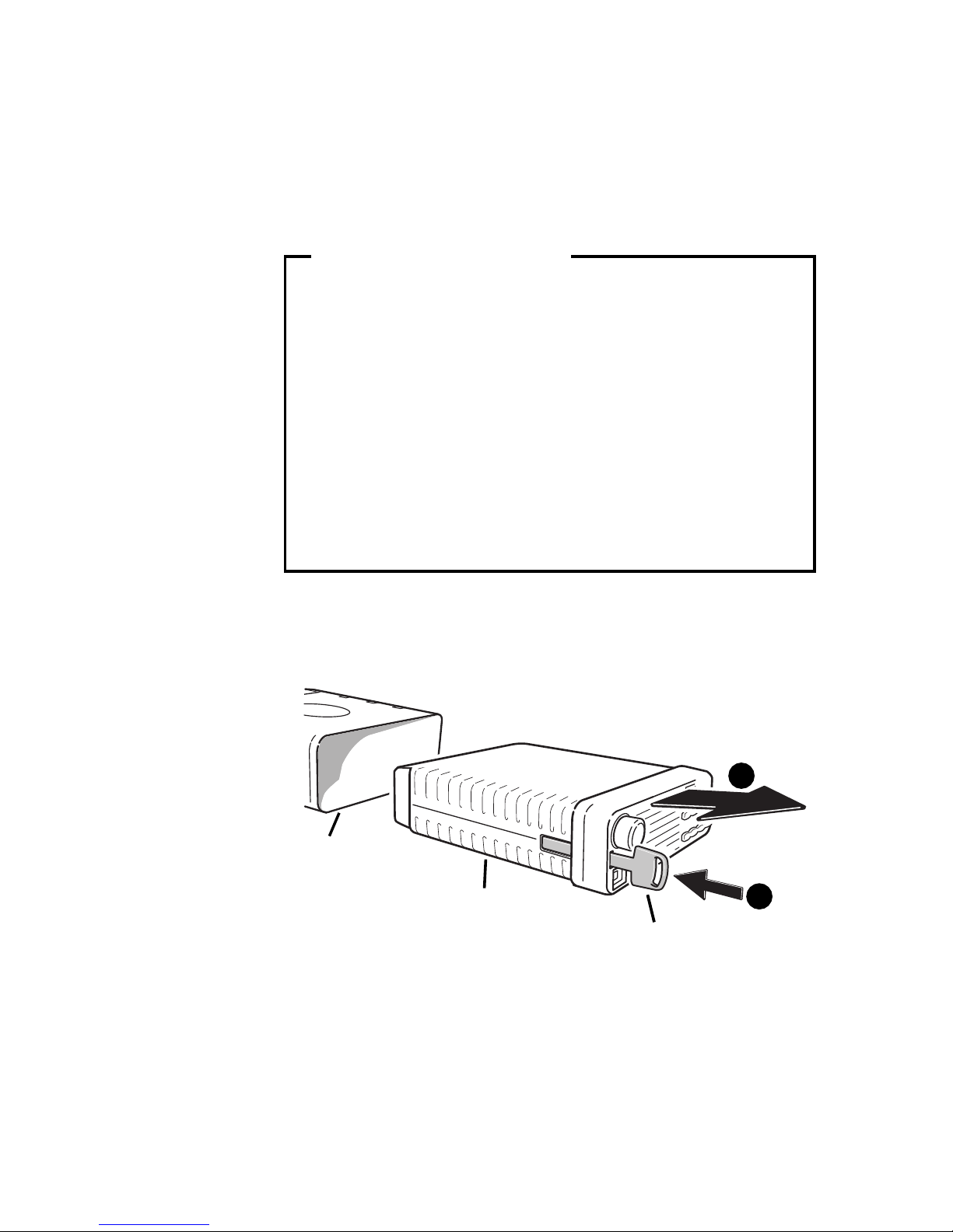
Remove the T2000 Radio from its cradle
2
cradle
T2000 radio
plastic key
1. Side the plastic key provided with the radio fully into the
small slot on the left front of the radio unit.
2. You can now slide the radio out forwards from the cradle, as
shown below:
1
10 Installing a T2000
Page 13

Disassemble the T2000 Cradle
The cradle consists of two outer covers made from metal, held
together by two plastic side mouldings. The plastic mouldings
have ribs that mate with the metal covers.
1
cradle
plastic rib
2
cover plate
1. To disassemble the cradle, place the tip of a small screw-
driver on the first protruding plastic rib, as indicated above.
Gently push down with the screwdriver. This will release the
2. Remove the metal cover plate. It is not necessary to disas-
first rib from the cover plate. Repeat for the other three
outer ribs.
semble the cradle further..
Installing a T2000 11
Page 14

Remove the Radio Cabinet
Warning: Some of the components inside the T2009 operate
at voltage levels that may be lethal. Do not remove the T2009
cover plate.
Unplug the T2009 from the mains supply.
1.
2. Remove the four mounting screws on the side of the
powers supply.
3. Remove the radio cabinet from the T2009, but do not
remove the T2009’s cover plate.
Mount the T2000 Cradle
The T2000 cradle is mounted inside the radio cabinet. The
mounting studs and mounting holes are shown above.
radio cabinet
1. Fit a washer on each of the mounting studs inside the radio
cabinet.
12 Installing a T2000
nut
3
cradle cover
2
washer
1
mounting stud
Page 15

2. Fit the metal cover plate onto the mounting studs. The end
of the cover plate that overhangs the plastic side mouldings, must face towards the rear of the supply.
3. Fit the nuts onto the protruding studs and fasten firmly.
Reassemble the T2000 Cradle
cradle outer cover
apply
pressure
cradle metal plate
apply
pressure
1. Position the cradle on the mounted cover plate, taking care
to locate the plastic ribs into their mating slots. They will
not fit if the cradle is back to front.
2. Clip the ribs home. This will require gentle pressure, with
your index fingers on the inside and thumbs on the outside,
as shown below.
radio cabinet
Mount the Radio Cabinet and T2000
Radio
1. Position the radio cabinet over the power supply so that the
mounting holes in the radio cabinet line up with the corresponding holes in the power supply.
2. Insert the screws and then tighten all four screws firmly.
3. Slide the radio, heatsink first, into the front of the cradle
until it seats firmly.
Installing a T2000 13
Page 16

Mount the Microphone clip
mounting holes
microphone clip
radio cabinet
ground strap
1. Mount the microphone clip to the side of the radio cabinet,
as shown below.
2. The power cable has a single black wire that ends in a
solder tag: this is the ground strap. For correct hookswitch
operation (as described in “Using the Microphone” on
page 5), fasten the ground strap’s solder tag to the microphone clip with one of the two microphone mounting
screws, as shown below.
Connect the Radio and the Power Supply
Note: The red and black wire of the power cable is positive.
ground strap
speaker connector
supply wires
1. Make sure that the radio and the T2009 are both turned off
and unplug the T2009 from the mains supply outlet.
14 Installing a T2000
T2000 power connector
Page 17

2. Connect the power cable’s positive (red and black) wire and
negative (black) wire to the positive and negative terminals
on the back of the T2009.
3. Plug the power cable into the power socket on the back of
the radio.
To Complete the Installation
1. If an external speaker is required, connect it as described in
the installation documentation for the speaker.
2. Make sure that the radio is switched off, as described in the
user documentation for the radio.
3. Plug the power supply into the mains supply outlet and
switch it on.
4. Make sure that the power indicator in the switch illumi-
nates. If the indicator fails to light up, check the connection
and mains power outlet. Turn to“Fault Finding Information”
on page 16 if the problem persists.
5. Connect the radio’s antenna.
6. Turn on the radio and make sure that it operates satisfacto-
rily, as described in the user documentation for the radio.
Installing a T2000 15
Page 18

Fault Finding Information
Power Switch Does Not Illuminate when
Turned On
Probable cause: No power in the AC outlet, or the main
input fuse inside the power supply is blown.
Suggested solution: Check the mains power outlet, or
replace the mains input fuse inside the unit (refer to the fuse
ratings on page 17)
Fuse Blows when Power is Turned On
Probable cause: Unit is defective
Suggested solution: Call technical support.
Output Voltage is 0 V or Very Low
Verify this fault condition with a multimeter.
Probable cause: The unit is in current limit condition.
Suggested solution: Check that the output terminals are
not shorted together.
16 Fault Finding Information
Page 19

Electrical Specifications
Input voltage
T2009-22 100 to 130VAC, 60Hz
T2009-21, T2009-23,
T2009-24
Output voltage 13.8VDC
Output ripple & noise
(on full load)
Output current, continuous 10A
Current limit 14A
Protection Over current, short circuit
Input fuse rating
T2009-22 3A
T2009-21, T2009-23,
T2009-24
200 to 250VAC, 50Hz
less than 10mV
and over voltage
2A
RMS
Note: Specifications may change without prior notice.
Fuse type 5mm x 20mm glass, 250V
Electrical Specifications 17
Page 20

Dec 03 IPN:M2009-00-001-804
www.taitworld.com
 Loading...