

Page 1

TM8260 Mobile Radios
Installation and Programming Guide
MMA-00041-04 · Issue 4 · October 2014
Page 2

Contact Information
Tait Communications
Corporate Head Office
Tait Limited
P.O. Box 1645
Christchurch
New Zealand
For the address and telephone number of regional
offices, refer to our website: www.taitradio.com
Copyright and Trademarks
All information contained in this document is the
property of Tait Limited. All rights reserved.
This document may not, in whole or in part, be copied,
photocopied, reproduced, translated, stored, or reduced
to any electronic medium or machine-readable form,
without prior written permission from Tait Limited.
The word TAIT and the TAIT logo are trademarks of
Tait Limited.
All trade names referenced are the service mark,
trademark or registered trademark of the respective
manufacturers.
Disclaimer
There are no warranties extended or granted by this
document. Tait Limited accepts no responsibility for
damage arising from use of the information contained
in the document or of the equipment and software it
describes. It is the responsibility of the user to ensure
that use of such information, equipment and software
complies with the laws, rules and regulations of the
applicable jurisdictions.
Enquiries and Comments
If you have any enquiries regarding this document, or
any comments, suggestions and notifications of errors,
please contact your regional Tait office.
Updates of Manual and Equipment
In the interests of improving the performance, reliability
or servicing of the equipment, Tait Limited reserves the
right to update the equipment or this document or both
without prior notice.
Intellectual Property Rights
This product may be protected by one or more patents
or designs of Tait Limited together with their
international equivalents, pending patent or design
applications, and registered trade marks: NZ409837,
NZ409838, NZ415277, NZ 415278, NZ 508806,
NZ511155, NZ516280/NZ 519742, NZ 521450,
NZ524369, NZ524378, NZ 524509, NZ 524537,
NZ530819, NZ534475, NZ 534692, NZ 547713,
NZ569985, NZ577009, NZ 579051, NZ 579364,
NZ580361, NZ584534, NZ 586889, NZ 592624,
NZ593887, NZ593888, NZ 600346, NZ 601933 ,
NZ607046, NZ607046, NZ 610426, NZ 610563,
NZ612027, NZ613565, NZ 615898, NZ 615954,
AU2004216984, AU321864, AU321868, AU339127,
AU339391, CN 1031871, CN 1070368,
CN200930004199.5, CN 200930004200.4,
CN200930009301.0, EU 000915475-0001,
EU000915475-0002, GB 2413445, US 12/870840,
US13/082767, US13/185498, US 13/465664, US13/
542062, US13/542147, US 13/763531, US 13/896969,
US14/032876, US 29/401234, US 29/401235,
US5745840, US640974, US 640977, US 7411461,
US7758996, US7937661, US 8301682.
This product may also be made under license under one
or more of the following U.S. Patents: 4,590,473
4,636,791 4,716,407 4,972,460 5,146,497 5,148,482
5,164,986 5,185,795 5,185,796 5,271,017 5,377,229
5,502,767.
The IMBE™ voice coding Technology embodied in
this product is protected by intellectual property rights
including patent rights, copyrights and trade secrets of
Digital Voice Systems, Inc. This voice coding
Technology is licensed solely for use within this
Communications Equipment. The user of this
Technology is explicitly prohibited from attempting to
decompile, reverse engineer, or disassemble the Object
Code, or in any other way convert the Object Code
into a human-readable form. Protected by U.S. Patents
5,870,405, 5,826,222, 5,754,974, 5,701,390, 5,715,365,
5,649,050, 5,630,011, 5,581,656, 5,517,511, 5,491,772,
5,247,579, 5,226,084 and 5,195,166.
Environmental Responsibilities
Tait Limited is an environmentally
responsible company which supports waste
minimization, material recovery and
restrictions in the use of hazardous
materials.
The European Union’s Waste Electrical and Electronic
Equipment (WEEE) Directive requires that this product
be disposed of separately from the general waste stream
when its service life is over. For more information
about how to dispose of your unwanted Tait product,
visit the Tait WEEE website at www.taitradio.com/
weee. Please be environmentally responsible and dispose
through the original supplier, or contact Tait Limited.
Tait Limited also complies with the Restriction of the
Use of Certain Hazardous Substances in Electrical and
Electronic Equipment (RoHS) Directive in the
European Union.
In China, we comply with the Measures for
Administration of the Pollution Control of Electronic
Information Products. We will comply with
environmental requirements in other markets as they are
introduced.
2 TM8260 Installation and Programming Guide
© Tait Limited October 2014
Page 3

Contents
Preface . . . . . . . . . . . . . . . . . . . . . . . . . . . . . . . . . . . . . . . . . . . . . . . . . . . . . 5
Scope of Manual . . . . . . . . . . . . . . . . . . . . . . . . . . . . . . . . . . . . . . . . . . . . . . . . . . . . 5
Associated Documentation . . . . . . . . . . . . . . . . . . . . . . . . . . . . . . . . . . . . . . . . . . . . . 5
Publication Record . . . . . . . . . . . . . . . . . . . . . . . . . . . . . . . . . . . . . . . . . . . . . . . . . . 6
Document Conventions . . . . . . . . . . . . . . . . . . . . . . . . . . . . . . . . . . . . . . . . . . . . . . . 6
1 Safety and Regulatory Warnings . . . . . . . . . . . . . . . . . . . . . . . . . . . . . . . . . 7
1.1 RF Exposure Hazard . . . . . . . . . . . . . . . . . . . . . . . . . . . . . . . . . . . . . . . . . . . . . 7
1.2 Vehicle Manufacturer’s Installation Instructions . . . . . . . . . . . . . . . . . . . . . . . . . . 7
1.3 MPT 1362 Code of Practice . . . . . . . . . . . . . . . . . . . . . . . . . . . . . . . . . . . . . . . . 7
1.4 Safe Radio Mounting . . . . . . . . . . . . . . . . . . . . . . . . . . . . . . . . . . . . . . . . . . . . . 8
1.5 Interference with Vehicular Electronics . . . . . . . . . . . . . . . . . . . . . . . . . . . . . . . . 8
1.6 Radio protection when charging the vehicle battery . . . . . . . . . . . . . . . . . . . . . . . 8
1.7 Preparation when Drilling Holes . . . . . . . . . . . . . . . . . . . . . . . . . . . . . . . . . . . . . 8
1.8 Radio Installation in Gas or Fuel Tankers. . . . . . . . . . . . . . . . . . . . . . . . . . . . . . .9
1.9 Vehicles Powered by Liquefied Petroleum Gas. . . . . . . . . . . . . . . . . . . . . . . . . . . 9
1.10 Non-standard Radio Installations. . . . . . . . . . . . . . . . . . . . . . . . . . . . . . . . . . . . . 9
1.11 IP54 Protection Class Considerations . . . . . . . . . . . . . . . . . . . . . . . . . . . . . . . . . 10
1.12 Negative Earth Supply . . . . . . . . . . . . . . . . . . . . . . . . . . . . . . . . . . . . . . . . . . . 10
2 Preparing the Installation . . . . . . . . . . . . . . . . . . . . . . . . . . . . . . . . . . . . . 11
2.1 Installation Tools . . . . . . . . . . . . . . . . . . . . . . . . . . . . . . . . . . . . . . . . . . . . . . . 11
2.2 Unpacking and Checking the Equipment for Completeness . . . . . . . . . . . . . . . . 11
2.3 Hardware and Firmware Compatibility . . . . . . . . . . . . . . . . . . . . . . . . . . . . . . . 13
2.4 Installation Considerations. . . . . . . . . . . . . . . . . . . . . . . . . . . . . . . . . . . . . . . . . 13
2.5 Installation Overview . . . . . . . . . . . . . . . . . . . . . . . . . . . . . . . . . . . . . . . . . . . . 14
2.6 Removing and Installing Grommets. . . . . . . . . . . . . . . . . . . . . . . . . . . . . . . . . . 15
3 Installing a Dual-Radio System . . . . . . . . . . . . . . . . . . . . . . . . . . . . . . . . . 16
3.1 Overview of Steps Required . . . . . . . . . . . . . . . . . . . . . . . . . . . . . . . . . . . . . . . 16
3.2 Checking the Required Firmware Versions and Software Features . . . . . . . . . . . 17
3.3 Downloading Configurations . . . . . . . . . . . . . . . . . . . . . . . . . . . . . . . . . . . . . . 17
3.4 Installing the Radio Bodies . . . . . . . . . . . . . . . . . . . . . . . . . . . . . . . . . . . . . . . . 21
3.5 Installing the Antennas . . . . . . . . . . . . . . . . . . . . . . . . . . . . . . . . . . . . . . . . . . . 25
3.6 Connecting the Power Cables to a Power Source. . . . . . . . . . . . . . . . . . . . . . . . 27
3.7 Connecting Remote Speakers . . . . . . . . . . . . . . . . . . . . . . . . . . . . . . . . . . . . . . 30
TM8260 Installation and Programming Guide Contents 3
© Tait Limited October 2014
Page 4

3.8 Installing a Cross-band Linking Cable . . . . . . . . . . . . . . . . . . . . . . . . . . . . . . . . 30
3.9 Installing the Control Head Solution . . . . . . . . . . . . . . . . . . . . . . . . . . . . . . . . . 32
3.10 Checking the Installation . . . . . . . . . . . . . . . . . . . . . . . . . . . . . . . . . . . . . . . . . 36
4 Programming a Dual-Radio System. . . . . . . . . . . . . . . . . . . . . . . . . . . . . . 37
4.1 Connecting a Dual-Radio System to a PC. . . . . . . . . . . . . . . . . . . . . . . . . . . . . 38
4.2 Programming a Dual-Radio System . . . . . . . . . . . . . . . . . . . . . . . . . . . . . . . . . 38
4.3 Recommended Dual-Radio Settings . . . . . . . . . . . . . . . . . . . . . . . . . . . . . . . . . 40
4.4 Crossband Repeater Settings . . . . . . . . . . . . . . . . . . . . . . . . . . . . . . . . . . . . . . . 42
4.5 Upgrading Radio Firmware . . . . . . . . . . . . . . . . . . . . . . . . . . . . . . . . . . . . . . . 44
4.6 Calibrating a Dual-Radio System . . . . . . . . . . . . . . . . . . . . . . . . . . . . . . . . . . . 44
4.7 Troubleshooting. . . . . . . . . . . . . . . . . . . . . . . . . . . . . . . . . . . . . . . . . . . . . . . . 45
5 Quick Reference . . . . . . . . . . . . . . . . . . . . . . . . . . . . . . . . . . . . . . . . . . . 46
Glossary . . . . . . . . . . . . . . . . . . . . . . . . . . . . . . . . . . . . . . . . . . . . . . . . . . . . 47
Tait Software License Agreement . . . . . . . . . . . . . . . . . . . . . . . . . . . . . . . . . . 49
4Contents TM8260 Installation and Programming Guide
© Tait Limited October 2014
Page 5

Preface
Scope of Manual
Warning Incorrect installation of your mobile radio may cause
damage to your vehicle which may result in death or serious
injury. You must read this manual before starting the installation!
This manual describes the installation and programming of TM8260 dual
mobile radio systems. A dual radio system is where two radio bodies are
connected together, and then connected to a control head solution.
The installation of accessories is described in the installation instructions
provided with the equipment, and the relevant section in the service
manual.
Associated Documentation
The following associated documentation is available for this product:
■ MMA-00040-xx TM8260 User’s Guide
■ MMA-00028-xx TM8100/TM8200 Installation Guide
■ MMA-00005-xx TM8100/TM8200 Service Manual
■ 402-00030-xx Crossband Linking Cable Installation Instructions
■ 402-00032-xx Cross-band Linking, GPS and External Interface
■ 402-00010-xx Remote Speaker Installation Instructions
■ 402-00042-xx Hand-Hand Control Head Installation Instructions
■ 402-00044-xx Hand-Held Control Head Remote Interface Kit
■ 402-00043-xx TM8260 Dual Head Upgrade Kit Installation
The characters xx represent the issue number of the documentation.
Updates to user documentation are published on the Tait support website.
Cable Installation Instructions
Installation Instructions
Instructions
Technical notes are published from time to time to describe applications for
Tait products, to provide technical details not included in manuals, and to
offer solutions for any problems that arise.
TM8260 Installation and Programming Guide Preface 5
© Tait Limited October 2014
Page 6

Publication Record
Issue Publication Date Description
01 March 2006 First release
02 July 2006 Hardware and firmware requirements added
03 November 2009 Hand-held control head information added
04 October 2014 “MAC address changed to “NTID”
Information on SFE keys added
Standby current amended
Programming settings updated
Dual head information added
Detailed current drain figures added
Hardware and firmware requirements expanded
Removing and installing grommets section added
Connecting to a PC section added
Product codes of cross-linking cables added
Document Conventions
Please follow exactly any instruction that appears in the text as an ‘alert’.
An alert provides necessary safety information as well as instruction in the
proper use of the product. This manual uses the following types of alert:.
Warning This alert is used when there is a hazardous situation
which, if not avoided, could result in death or serious injury.
Caution This alert is used when there is a hazardous situation which,
if not avoided, could result in minor or moderate injury.
Notice This alert is used to highlight information that is required to
ensure procedures are performed correctly. Incorrectly performed procedures could result in equipment damage or malfunction.
This icon is used to draw your attention to information that may improve
your understanding of the equipment or procedure.
Within this manual, the following symbols are used to highlight differences
between radios with a transmit power of more than
transmit power of
25W and radios with a
25W:
This symbol highlights information that is relevant to radios with a transmit
>25W
power >25W.
This symbol highlights information that is relevant to radios with a transmit
25W
6Preface TM8260 Installation and Programming Guide
power of 25W.
© Tait Limited October 2014
Page 7

1 Safety and Regulatory Warnings
This section contains important information on the safe installation of the
radio system. You must read this information before starting the installation.
You must also read and observe the safety information on radio operation
provided in the safety and compliance information and the user’s guide.
1.1 RF Exposure Hazard
To comply with FCC RF exposure limits:
For radios with a transmit power > 25 W:
>25W
25W
■ VHF radios must be installed using an antenna mounted centrally on the
vehicle roof, with a gain of 2.15 dBi or 5.15 dBi.
■ UHF and 800MHz radios must be installed using an antenna mounted
either centrally on the roof with a gain of 2.15dBi or 5.65 dBi, or
centrally mounted on the trunk with a gain of 5.65dBi.
For radios with a transmit power of 25 W:
■ The radio must be installed using an externally mounted antenna with a
gain of either 2.15dBi or 5.15dBi.
In all cases, the antenna must not be mounted at a location such that any
person or persons can come closer than 35 inches (0.9m) to the antenna.
1.2 Vehicle Manufacturer’s Installation Instructions
Installation of this product in a vehicle must be performed according to the
instructions provided by the vehicle manufacturer. For more information,
refer to the vehicle manufacturer’s website or contact the vehicle
manufacturer’s dealer.
1.3 MPT 1362 Code of Practice
Mobile radios should be installed in accordance with the MPT 1362 Code
of Practice.
TM8260 Installation and Programming Guide Safety and Regulatory Warnings 7
© Tait Limited October 2014
Page 8

1.4 Safe Radio Mounting
Warning Mount the radio securely so that it will not break
loose in the event of a collision. An unsecured radio is dangerous
to the vehicle occupants.
■ Mount the radios and the microphones where they will not interfere
with:
■ the deployment of passenger airbags
■ the vehicle operator controls
■ the vehicle operator’s view
■ Do not mount the radios vertically, with the remote interface facing
down. This will violate compliance with the standards UL/CSA/
EN 60950, Safety of Information Technology Equipment.
1.5 Interference with Vehicular Electronics
Warning Some vehicular electronic devices may be prone to
malfunction due to the lack of protection from RF energy when
your radio is transmitting.
Examples of vehicular electronic devices that may be affected by RF
energy are:
■ electronic fuel injection systems
■ electronic anti-skid braking systems
■ electronic cruise control systems
■ indicators
If the vehicle contains such equipment, consult the vehicle manufacturer or
dealer to determine whether these electronic circuits will perform normally
when the radio is transmitting.
1.6 Radio protection when charging the vehicle battery
Always remove the fuses from the radio power cable before charging the
vehicle battery, connecting a second battery, or using power from another
vehicle (e.g. when jump-starting the vehicle).
1.7 Preparation when Drilling Holes
Warning When drilling holes in the vehicle, check that drill-
ing at the selected points will not damage existing wiring, fuel
tanks, fuel and brake lines, or battery cables.
8 Safety and Regulatory Warnings TM8260 Installation and Programming Guide
© Tait Limited October 2014
Page 9

1.8 Radio Installation in Gas or Fuel Tankers
Special conditions must be observed when installing a radio on gas and fuel
tankers. Consult your radio provider or Tait-accredited service center for
more details.
1.9 Vehicles Powered by Liquefied Petroleum Gas
Warning Radio installation in vehicles powered by LPG (liq-
uefied petroleum gas) with the LPG container in a sealed-off
space within the interior of the vehicle must conform to the
National Fire Protection Association Standard NFPA 58.
This standard states that the radio equipment installation must
meet the following requirements:
■ The space containing the radio equipment shall be
isolated by a seal from the space containing the LPG
container and its fitting.
■ Outside filling connections shall be used for the LPG
container and its fittings.
■ The LPG container space shall be vented to the outside of
the vehicle.
1.10 Non-standard Radio Installations
The installation U-bracket described in this guide has been designed so that
there is enough airflow around the radio body to provide cooling.
If a non-standard installation method is used, care must be taken that
sufficient heat can be dissipated from the heatsink fins and the ridged bottom
surface of the radio.
For this to be achieved, there must be a gap of more than 3/8 inch (10 mm)
between the bottom surface of the radio chassis and the mounting surface.
This is illustrated in Figure 1.1:
Figure 1.1 Gap between radio chassis and mounting surface
10 mm (3/8 in.)
mounting surface
TM8260 Installation and Programming Guide Safety and Regulatory Warnings 9
© Tait Limited October 2014
Page 10

1.11 IP54 Protection Class Considerations
A dual radio system fulfils the requirements of the IP54 protection class.
Notice However, do not mount the radio in areas where it can be
temporarily submerged from an accumulation of water or other liquids
(e.g. when using a high-pressure cleaning device).
The IP54 protection class does not apply when:
■ a remote interface is removed from the radio body or control head.
■ the bungs are removed from the auxiliary connector or the cavity for the
external options connector (fitting an auxiliary connector or external
options connector will not restore the IP54 protection class)
■ a grommet is not installed. For example, grommets on the radio
connecting cable, control-head remote cable, and microphone cord.
■ adding an accessory that is not rated to IP54, for example, a crossband
cable, control-head interface box, or hand-held control-head remote
interface box.
1.12 Negative Earth Supply
The radios are designed to operate only in a negative earth system.
10 Safety and Regulatory Warnings TM8260 Installation and Programming Guide
© Tait Limited October 2014
Page 11

2 Preparing the Installation
This section contains the following information:
■ Installation Tools
■ Unpacking and Checking the Equipment for Completeness
■ Hardware and Firmware Compatibility
■ Installation Considerations
■ Installation Overview.
2.1 Installation Tools
The following tools are required to install the radio system:
■ drill and drill bits
■ 5mm (3/16 inch) flat-bladed screwdriver
■ To r x T- 1 0 s c r e w d r iv e r
■ To r x T- 2 0 s c r e w d r iv e r
■ Pozidr iv screwdriver
■ 8 mm (5/16 inch) socket
■ wire cutters/strippers
■ RF connector crimp tool
■ fuse crimp tool
■ in-line RF power meter capable of measuring forward and reflected
power at the operating frequency of each radio.
2.2 Unpacking and Checking the Equipment for Completeness
To install a dual-radio system, you require the following equipment. For
information on the version number of equipment required, see “Hardware
and Firmware Compatibility” on page 13.
■ 2 x radio bodies, such as TMAB22-B100C and TMAB22-H600C.
■ 2 x body remote interfaces (TMAC31-0T).
■ 2 x radio body installation kits, appropriate for your required mounting
arrangement, and the radio’s transmit power and antenna connection.
Examples include the U-bracket installation kits TMAA03-01 (for 25W
radios with BNC connector), TMAA03-17 (for >25W radios with
mini-UHF connector), and TMAA03-22 (for >25W radios with BNC
connector), or the slide-in cradle installation kit TMAA03-18 (for 25W
radios with BNC connector).
TM8260 Installation and Programming Guide Preparing the Installation 11
© Tait Limited October 2014
Page 12

Warning Danger of fire. The radio’s protection mechanisms
rely on the correct fuses on both the negative and positive power
supply leads being present. Failure to fit the correct fuses may
result in fire or damage to the radio.
The correct fuse types are:
■ >25W radios: 20A fuses (Tait IPN 265-00010-81)
25W>25W
■ 25W radios: 10A fuses (Tait IPN 265-00010-80).
■ control head solution. Either:
■ graphical control head (TMAC40-0T) with remote interface
(TMAA03-03), remote cable (TMAA04-01), and microphone
(such as rugged (TMAA02-01) or keypad (TMAA02-08)),
■ graphical control head (see above) with dual head upgrade
(TMAA11-09
■ hand-held control head (TMAC70-xx).
■ radio connecting cable (TMAA04-03).
■ 2 x antennas
*
appropriate for your radio frequency band or bands, and
antenna coaxial cable
*
), or
a
.
The following equipment is optional:
■ cross-band cable, such as TMAA04-06.
■ 2 x remote speakers
■ components
*
*
, such as TMAA10-03.
for the additional connectors, if available, on your crossband cable. Examples include components to connect to an external alert
device, ignition signal, or a GPS antenna/receiver.
a. Not included in a typical TM8260 package. This equipment may need to
be obtained or ordered separately.
12 Preparing the Installation TM8260 Installation and Programming Guide
© Tait Limited October 2014
Page 13

2.3 Hardware and Firmware Compatibility
Body remote
Radio FW
a
interface
(TMAC31-0T)
HW
Head HW
Head remote
HW
PC software
TM8260 with
one graphicaldisplay control
head
TM8260 with
two graphicaldisplay control
heads
TM8260 with
one hand-held
control head
TM8260 with
two hand-held
control heads
a. Firmware of all devices (heads and bodies) in the radio system
b. For more information on how the hardware subassembly revision number relates to your serial number, contact
your regional office or Tait Technical Support (see page 2).
c. Software version described in this document.
Radio
application and
DSP firmware
v4.02, boot
code v1.07
Radio
application and
DSP firmware
v5.02, boot
code v1.07
Not currently supported.
Hardware
subassembly
XMAC31
revision 002
and PCB 22001720-05
Hardware
subassembly
XMAC40
b
,
revision 009
Hardware
subassembly
XMAC70-MA
revision 002
and PCB 22002149-05
Hardware
subassembly
XMAA03-03
b
revision 003
and PCB 22001721-04
N/A TM8200
b
,
b
,
TM8200
Programming
Application v4.01 or
TM8200/TM9300/
TP9300
Programming
Application, v1.03
TM8000 Calibration
Application v4.03
Programming
Application v5.10 or
TM8200/TM9300/
TP9300
Programming
Application, v1.03
TM8000 Calibration
Application v4.03
c
,
c
,
2.4 Installation Considerations
Inspect the vehicle and determine the safest and most convenient position
for mounting the radio bodies and control head, and routing the various
cables. The radio bodies must be less than 4.9ft (1.5m) apart.
Notice If using accessories that do not provide IP54 protection (for
example, a crossband cable, control-head interface box, or hand-held
control head remote interface box), choose a mounting position away
from water, dust, and other environmental hazards.
TM8260 Installation and Programming Guide Preparing the Installation 13
© Tait Limited October 2014
Page 14

2.5 Installation Overview
Figure 2.1 summarizes how the components in a dual-radio system are
installed. For more detailed instructions, see “Installing a Dual-Radio
System” on page 16.
Figure 2.1 TM8260 dual body installation overview
g
h
optional
required
to antenna
to power supply
to speaker
c
d
e
f
b
Control head example
1#
1$
1!
to second antenna
to power supply
to speaker
other
connectors
b
I
j
1)
1@
Notice The configuration shown must be
followed to ensure proper functionality.
external speaker
b
flying lead connector
c
cross-band linking, GPS, and
d
external interface cable
radio body
e
body remote interface with
f
link J4 fitted Control head example:
grommet
g
radio connecting cable
h
other connectors from cross-
i
band cable, for example, to
GPS antenna/receiver, external
alert device, ignition signal
radio body
j
body remote interface with
1)
link J4 removed
to control head, such as graphical-
1!
display (see example) or hand-held
control head remote cable
1@
control head remote interface
1#
graphical-display control head
1$
supported microphone
1%
1%
14 Preparing the Installation TM8260 Installation and Programming Guide
© Tait Limited October 2014
Page 15

2.6 Removing and Installing Grommets
Grommets ensure that the radio system and all connections are sealed against
water, dust and other environmental hazards. A dual radio system requires a
grommet in the unused remote-interface port (item
Figure 2.2page 15). A dual radio system also requires all cable grommets to
be installed.
g
in
Removing a
grommet
1. Using your thumb or forefinger, lift up one of the corners of the
microphone grommet. Firmly (but gently) pull that corner until the
seal comes away from the cavity. See Figure 2.2.
Figure 2.2 Removing a grommet
gromm
2. Repeat to expose another corner.
3. Pull the exposed corners back and remove the grommet.
4. If removing a cable grommet, slide the grommet along the cable to
reveal the plug.
Installing grommets 5. If installing a cable grommet, slide the grommet along the cable.
6. Push two adjacent corners of the grommet into the socket cavity.
7. Squeeze the grommet and push the remaining corners into position.
8. Check that the grommet is seated correctly in the cavity.
See Figure 2.3.
Figure 2.3 Correct seating when installing a grommet
TM8260 Installation and Programming Guide Preparing the Installation 15
© Tait Limited October 2014
Page 16

3 Installing a Dual-Radio System
This section describes how to install all components in a dual radio system,
including downloading NTIDs and removing link J4, installing the radio
bodies and control head, connecting the radio system to a power source, and
installing antennas and remote speakers.
3.1 Overview of Steps Required
Before you start, make sure you have all the necessary tools and components.
See page 11 for more information.
1. Check that the all devices in the radio system have the same firmware,
and the radio bodies have the necessary software features. See
“Checking the Required Firmware Versions and Software Features”
on page 17.
2. Download NTIDs to all devices in the system. See “Downloading
Configurations” on page 17.
3. Remove link J4 from the radio body interface that will be connected
to the control head. See “Removing Link J4” on page 21.
4. Assemble the body interfaces. See “Assembling the Body Remote
Interfaces” on page 22.
5. Mount the radio bodies. See “Mounting the Radio Bodies” on
page 23.
6. Install the radio connecting cable. See “Installing the Radio
Connecting Cable” on page 23.
7. Install the antennas. See “Installing the Antennas” on page 25.
8. Connect the radios to a power source. See “Connecting the Power
Cables to a Power Source” on page 27.
9. (Optional) Connect remote speakers (see “Connecting Remote
Speakers” on page 30) and a cross-band cable (see “Installing a Crossband Linking Cable” on page 30).
10. Install the control head or heads. See “Installing the Control Head
Solution” on page 32.
11. Install the fuses and check the installation. See “Checking the
Installation” on page 36.
16 Installing a Dual-Radio System TM8260 Installation and Programming Guide
© Tait Limited October 2014
Page 17
3.2 Checking the Required Firmware Versions and Software Features
Check that the firmware version of all devices (radio bodies and control
head) is the same. If not, upgrade the appropriate devices by connecting the
control head directly to a radio body (see Figure 3.3 on page 19 and
Figure 3.4 on page 20). For the firmware version and programming
application version to use, see “Hardware and Firmware Compatibility” on
page 13. For more information, click the Help [?] button from the
programming application’s Download dialog (Tools > Download).
Check that both radio bodies have the software feature for Multi-Body
Support enabled (default factory configuration). If you are installing dual
heads, both radio bodies will also need the software feature for Multi-Head
Support enabled. For more information, click the Help button from the
programming application’s Optional Features dialog (Tools > Optional
Features).
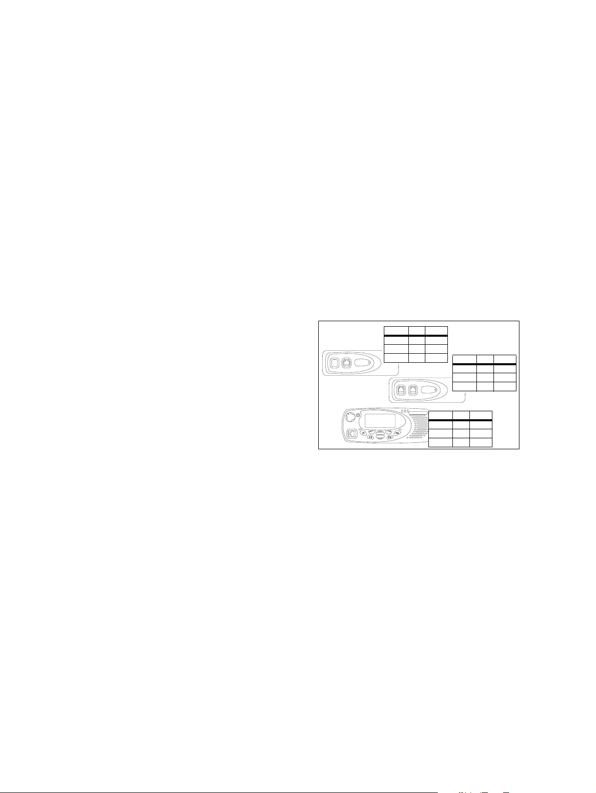
3.3 Downloading Configurations
Every device (head and
body) in a TM8260 radio
system must have a
system configuration
table (SCT) downloaded,
with unique NTID
(network ID) addresses
(Figure 3.1). This enables
all devices to operate
together. If there is a
problem with the SCT or
Figure 3.1 Devices with SCTs downloaded
Type NTID Priority
TMACxx 2 2
TMABxx 1 1
TMABxx 3 3
Type NTID Priority
TMACxx 2 2
TMABxx 1 1
TMABxx 3 3
Type NTID Priority
TMACxx 2 2
TMABxx 1 1
TMABxx 3 3
a device does not have a
unique NTID, then the radio will display “Duplicate NTIDs”.
You may need to remove link J4 and assemble the remote interfaces before
downloading NTIDs. For example, you may be using a hand-hand control
head. For more information, see:
■ “Removing Link J4” on page 21
■ “Assembling the Body Remote Interfaces” on page 22
■ “Assembling the Control Head Interface” on page 32.
If you need to download NTIDs to devices in an already installed system,
make sure you first disconnect the radio connecting cable (item
h
in
Figure 2.2 on page 15).
1. From the Programming Application, click Tools > Download and
then Device Configuration > Advanced.
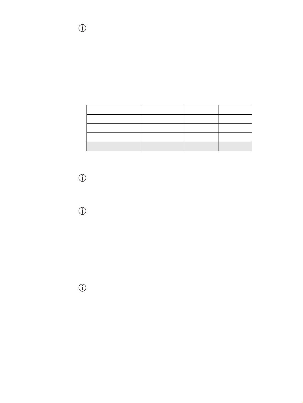
2. Make sure a table similar to Figure 3.2 is displayed in the dialog.
TM8260 Installation and Programming Guide Installing a Dual-Radio System 17
© Tait Limited October 2014
Page 18
The radio body with the lowest NTID determines the foreground radio
the first time the system is turned on, and each subsequent time if the
Power-up on Last Active Body check box is cleared in the programming application.
Either:
■ click File > Open, and open the device configuration file for the
system, or
■ click Edit > Add Device and define the table.
Figure 3.2 Example of a system configuration table
Type Name NTID Priority
Head (TMACxx) Head 2 2
Body (TMABxx) VHF Radio 1 1
Body (TMABxx) UHF Radio 3 3
Head (TMACxx)
a
2nd Head 4 4
a. A second “Head” row should only be added if dual control heads will be installed
with the radio system.
The system configuration table must be downloaded to devices in the
order stated within these steps. If not, then the control head may receive
the same address as a radio body and you will no longer be able to communicate with all or part of the system.
The entire table must be downloaded to each device, not just information about the device that the table is intended for. See Figure 3.1.
3. Connect the control head directly to the radio body that you want to
assign with the highest numerical NTID value (in the example table
in Figure 3.2, this is the UHF radio), and apply power.
■ If connecting a control head with graphical display, see Figure 3.3
diagram
■ If connecting a hand-held control head, see Figure 3.3 diagram
b, or diagram c.
d.
Connect one radio body at a time. Do not attempt to download NTIDs
if both radio bodies are connected together and have power applied.
18 Installing a Dual-Radio System TM8260 Installation and Programming Guide
© Tait Limited October 2014
Page 19
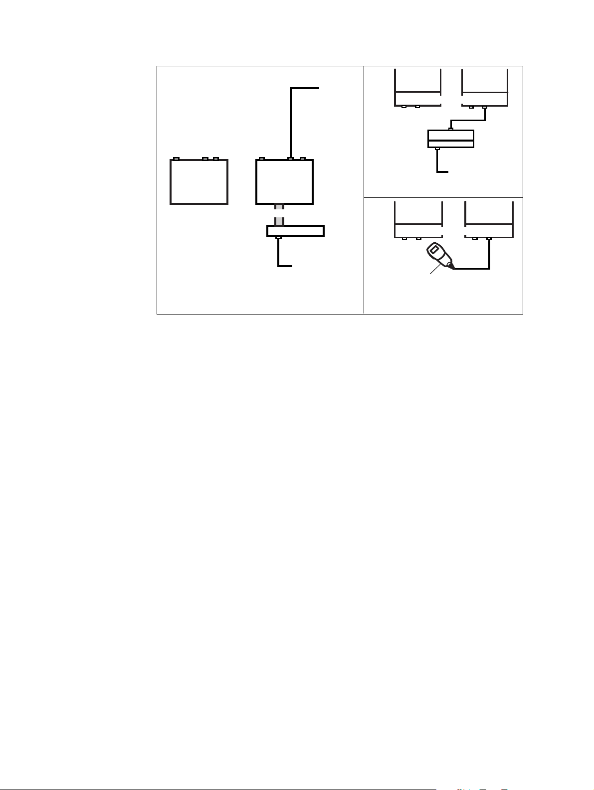
Figure 3.3 UHF radio body connected directly to the control head
VHF radio
control head loom
b Graphical control-head
(before interfaces are installed)
4. Connect the control head microphone port to your PC.
5. Click Radio > Download Configuration, and download the table
to device TMABxx with the higher address.
UHF radio
control head
to PC
to power
supply
VHF radio
body remote interfaces
control head
remote interface
c Graphical control-head
(after interfaces are installed)
VHF radio
body remote interfaces
to PC
d Hand-held control head
(requires body remote interfaces)
UHF radio
Control head
To PC
control-head
curly cord
remote cable
UHF radio
6. Connect the control head directly to the radio body that will have the
lowest numerical NTID value (in the example table in Figure 3.2, this
is the VHF radio), and apply power.
7. If connecting a control head with graphical display, see Figure 3.4
diagram
8. If connecting a hand-held control head, see Figure 3.4 diagram
b, or diagram c.
d.
TM8260 Installation and Programming Guide Installing a Dual-Radio System 19
© Tait Limited October 2014
Page 20
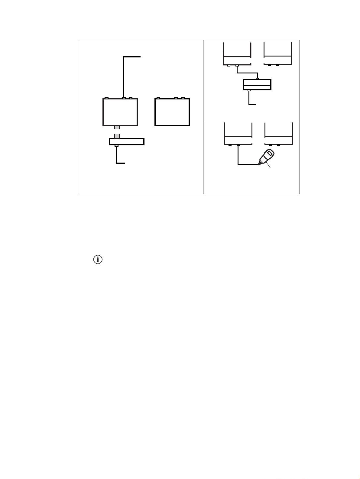
Figure 3.4 VHF radio body connected directly to the control head
VHF radio
control head loom
control head
to PC
b Graphical control-head
(before interfaces are installed)
9. Click Radio > Download Configuration again, and download the
same table to device TMABxx with the lower address.
to power
supply
UHF radio
VHF radio
body remote interfaces
control head
remote interface
c Graphical control-head
(after interfaces are installed)
VHF radio
body remote interfaces
control-head
curly cord
d Hand-held control head
(requires body remote interfaces)
UHF radio
remote cable
control head
to PC
UHF radio
to PC
10. Click Radio > Download Configuration a third time, and
download the same table to the control head (device TMACxx).
If installing a second control head using the upgrade kit TMAA11-09,
connect the second control head to a radio body and repeat step 10 for
device TMACxx with the higher NTID.
11. Check that all red indicators in the table are now green.
20 Installing a Dual-Radio System TM8260 Installation and Programming Guide
© Tait Limited October 2014
Page 21
3.4 Installing the Radio Bodies
To prepare and install the radio bodies, you must:
■ remove link J4 from the radio body interface that will be connected to
the control head,
■ assemble the body interfaces,
■ mount the radio bodies, then
■ install the radio connecting cable.
Removing Link J4
Every body remote interface (TMAC31-0T) is manufactured, by default,
with a 120Ω termination resistor across the RS485 signal lines. The control
head remote (TMAA03-03) also has this termination.
This termination is required at the ends of an RS485 network. In the case
of a TM8260 dual-radio system, the radio body with the two connections
(to the control head and to the other radio body) is a node on the network
and must not have this termination.
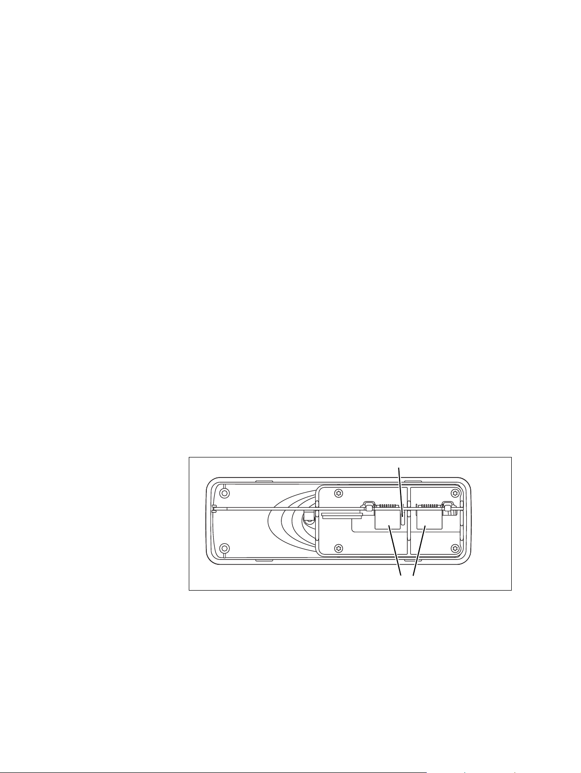
To remove this termination, use your fingernail (or similar) to remove the
jumper (shorting link) J4. Link J4 is located between the two RJ45
connectors (see Figure 3.5), and can be removed without removing the
PCB.
This must only be removed on the body remote interface connected to the
control head (item
1) in Figure 2.1 on page 14), and can only be removed
when the interface is separate from the radio body. If the interface has
already been installed, see “Removing the Body Interface” on page 22.
Figure 3.5 Location of link J4
link J4
RJ45 connectors
TM8260 Installation and Programming Guide Installing a Dual-Radio System 21
© Tait Limited October 2014
Page 22
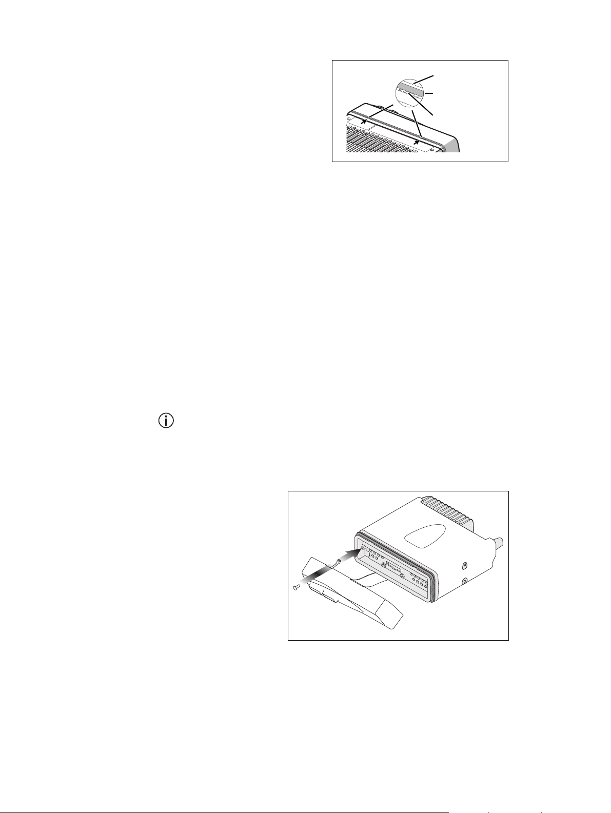
Removing the Body
Interface
1. On the underside of the
Figure 3.6 Removing the body interface
radio, insert a 5mm (3/
16in.) flat-bladed screwdriver between the body
lever point
seal
interface and the seal, in
the positions shown
(Figure 3.6).
indication of
lever point
Insertion points and are
lever points and are indicated on the radio chassis
by a dot-dash-dot pattern (
).
•
•
–
Notice Take care that the seal is not damaged. Damage to this seal
reduces environmental protection.
2. Use the screwdriver to lift the remote interface off the chassis clip,
then repeat in the other position.
You should now be able to inspect, and if necessary remove, shorting
link J4. It is not necessary to remove the body interface loom or the
earthing tag to remove the link.
Assembling the Body Remote Interfaces
The following steps show how to connect a body remote interface to a radio
body. Complete these steps for both radio bodies.
One remote interface must have link J4 removed. See “Removing Link
J4” on page 21 for more information. After you install the interface with
link J4 removed, make sure you can identify that radio body when connecting the cables afterwards. If necessary, mark the radio body with an
appropriate label or similar.
1. Screw the earthing tag onto the
left screw boss on
the radio chassis,
using the Torx T10 screw provided.
22 Installing a Dual-Radio System TM8260 Installation and Programming Guide
© Tait Limited October 2014
Page 23
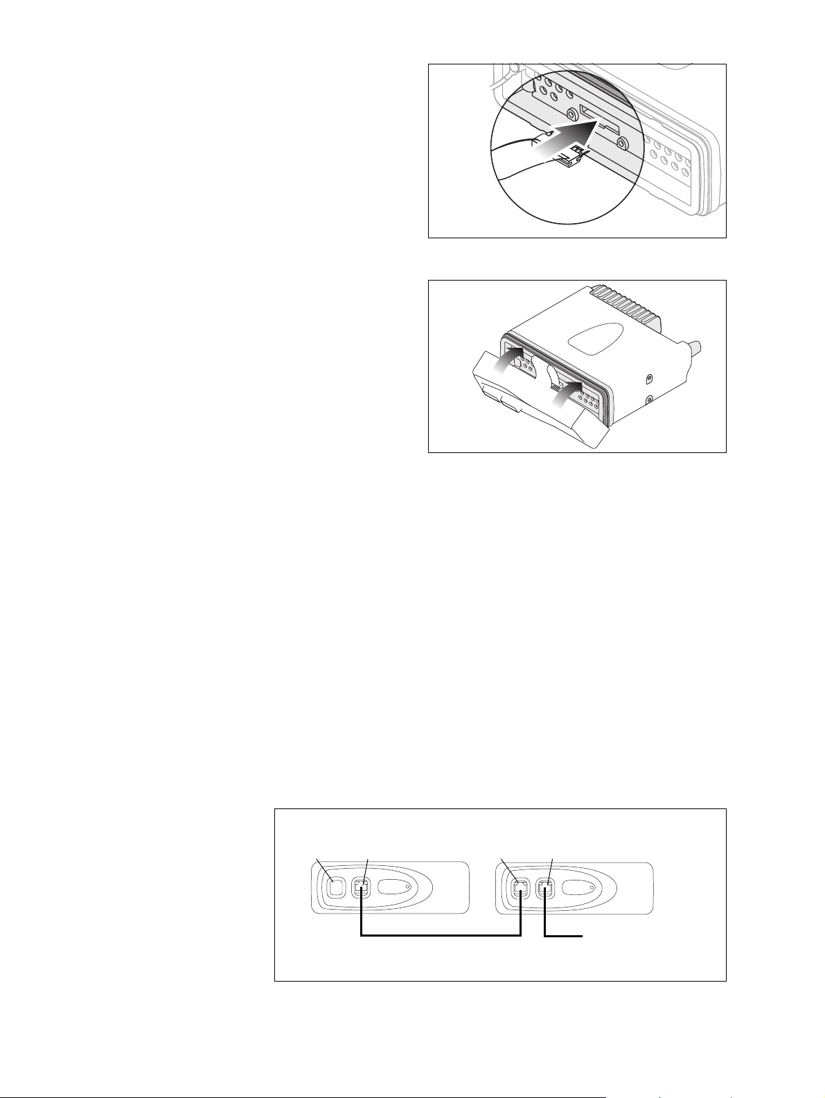
2. Plug the body-
interface loom
onto the controlhead connector.
Notice When
mounting the control head, make sure
you do not pinch
and damage the
loom.
3. Insert the bottom
edge of the
control head
onto the two
clips in the front
of the radio
chassis, then snap
into place.
Mounting the Radio Bodies
Mount the two radio bodies less than 1.5 metres (4.9ft.) apart using the
preferred mounting method (such as U-brackets, slide-in cradles, or security
brackets).
For more information, refer to the instructions included with the cradle or
bracket installation kit.
Installing the Radio Connecting Cable
Figure 3.7 contains an overview of the connections between both radio
bodies and the control head. For information on the pins and signals of all
ports, see “Pins and Signals” on page 24.
Figure 3.7 Overview of connections between radio bodies and control
head
body with link J4 fitted
outermost
port
innermost
port
body with link J4 removed
outermost
port
innermost
port
to control head
radio connecting cable
TMAA04-03 (1.5 m / 4.9 ft.)
TM8260 Installation and Programming Guide Installing a Dual-Radio System 23
© Tait Limited October 2014
solution
Page 24
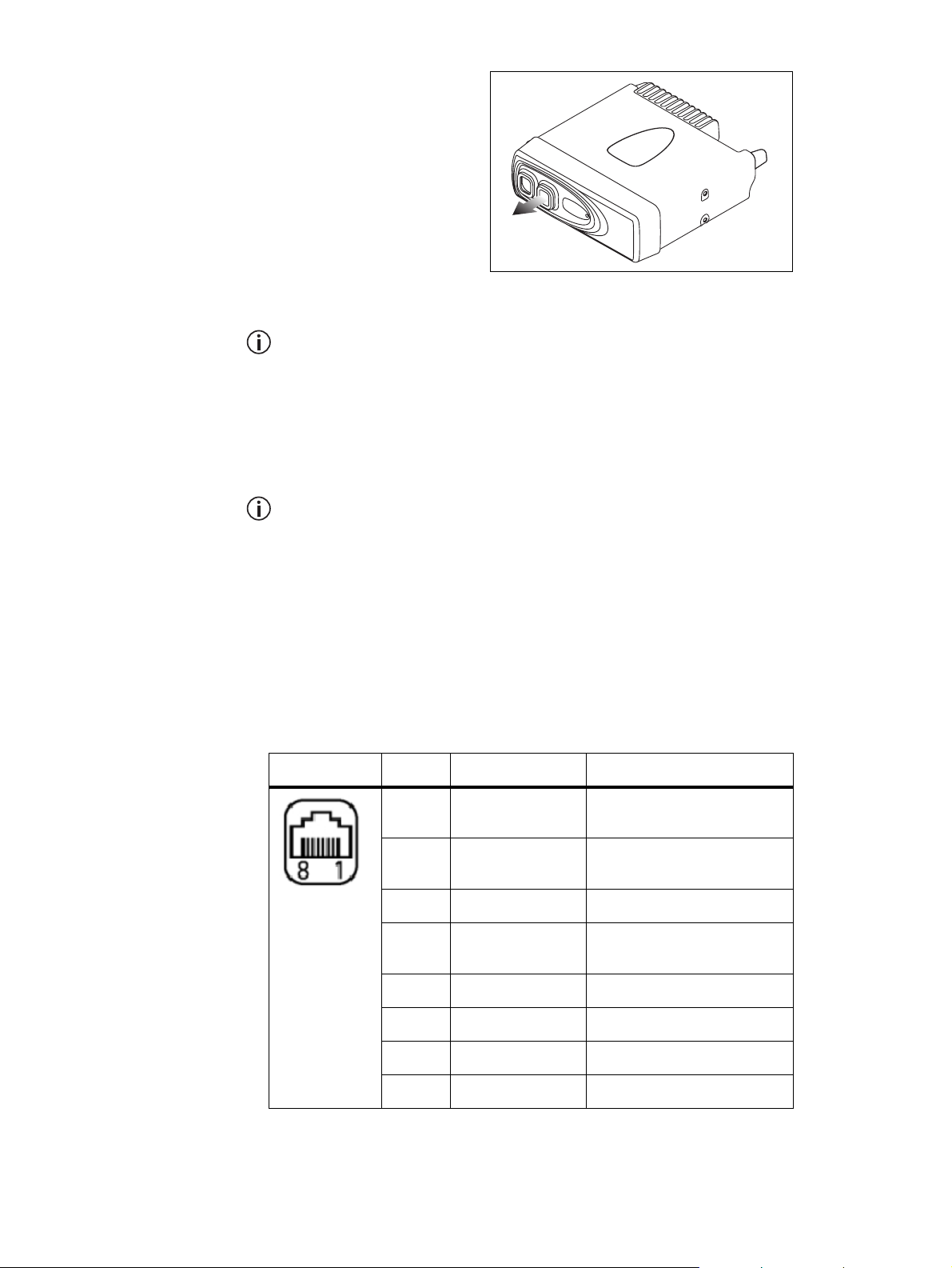
Detailed Steps
1. Remove all appropriate
grommets. See
“Removing and
Installing Grommets”
on page 15.
The outermost port of
the radio body with
link J4 fitted is not
used. Leave the grommet installed in this
port (item
in Figure 2.2 on page 15).
g
If a radio body does not have link J4 removed, or you cannot identify the
correct radio body to use, you will need to disassemble one or both interfaces. See “Removing the Body Interface” on page 22 for more infor-
mation.
2. Attach one end of the radio connecting cable to the outermost port
of the radio body with link J4 removed.
The innermost port of this radio connects to the control head solution.
3. Attach the other end of the radio connecting cable to the innermost
port of the other radio body.
4. Install the cable grommets. See “Removing and Installing
Grommets” on page 15.
Pins and Signals The pinouts in Table 3.1 are for the two RJ45 ports on the radio body
interface, and single RJ45 port on the control head interface.
Table 3.1 Remote interface ports—pins and signals
Pin Name Description
1 RX_AUDIO Analogue receive audio – after
volume control.
2 13V8 Default setting is a switched
+13V8 line.
front view
3 RS485+ RS485 data.
4 AGND/PTT Default setting is analogue
ground.
5 MIC AUDIO Analogue electret mic input.
6 RS485 RS485 data.
7 DGND Digital ground.
8 ON/OFF Radio on/off control.
24 Installing a Dual-Radio System TM8260 Installation and Programming Guide
© Tait Limited October 2014
Page 25

3.5 Installing the Antennas
A separate antenna for each radio is recommended, rather than a single
antenna configuration (such as a multi-band antenna with a duplexer or
splitter). See “Installation Overview” on page 14. Use ground-independent
antennas if no suitable ground plane is available.
It is important that the antennas are separated as far as possible from each
other, such as opposite corners of the vehicle, to reduce interference. MPT
1362 recommends a separation of at least ¼ wavelength for transmit
frequencies below 600 MHz and one wavelength for transmit frequencies
above 600MHz. Use the largest separation requirement of the two radio
bodies. See Table 3.2 below, and “MPT 1362 Code of Practice” on page 7.
Notice You may need to install additional equipment such as filters if:
■ your installation environment does not allow for proper
separation,
■ the channel frequencies of the two radios are similar, or
■ after testing you experience poor performance or interference.
If the above cases apply to your installation, or you are unsure of the
equipment to install, contact an antenna specialist for further advice.
Table 3.2 Approximate frequency to wavelength conversion
Band Name Frequency (MHz) Wavelength (cm)
A4 (lower range) 66 454 114
A4 (upper range) 88 341 85
B1 (lower range) 136 220 55
B1 (upper range) 174 172 43
H6 (lower range) 450 67 17
H6 (upper range) 530 57 14
1/4 Wavelength
(cm)
Install the antennas according to the antenna manufacturer’s instructions.
Good quality 50Ω coaxial cable must be used, such as RG58 or UR76.
Notice Route the cables in a manner that minimizes:
■ coupling into the electronic control systems of the vehicle
■ coupling of electric vehicle systems, such as alternators, into the
radio
Avoid sharp bends in the cables. These distort the cable and alter its
electrical characteristics.
TM8260 Installation and Programming Guide Installing a Dual-Radio System 25
© Tait Limited October 2014
Page 26
Warning RF exposure hazard!
To comply with FCC RF exposure limits, mount the antenna at
a location such that no person or persons can come closer than
35 inches (0.9m) to the antenna.
For >25W radios:
>25W
25W
■ VHF radios must be installed using an antenna mounted
centrally on the vehicle roof, with a gain of 2.15dBi or
5.15dBi.
■ UHF and 800MHz radios must be installed using an
antenna mounted either centrally on the roof with a gain
of 2.15dBi or 5.65dBi, or centrally mounted on the trunk
with a gain of 5.65dBi.
For 25W radios:
■ The radio must be installed using an externally mounted
antenna with a gain of either 2.15dBi or 5.15 dBi.
Terminating the
Antenna Cable
1. Run one antenna cable (not supplied) from an antenna to the mounting location of the matching radio body. Cut the cable to length,
allowing approximately 20 cm (8 in.) excess at the radio end.
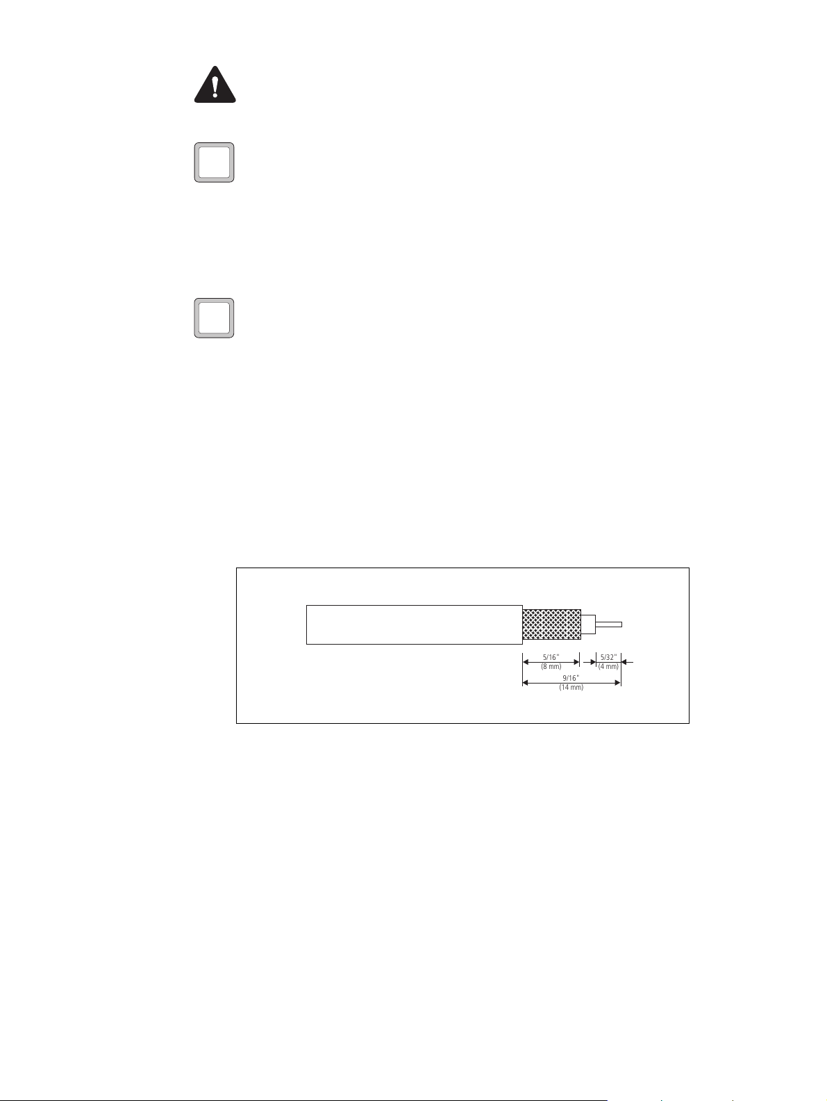
2. Terminate the free end of the antenna cable with the mini-UHF plug
or BNC plug (supplied) as shown in Figure 3.8.
3. Repeat steps 1 and 2 for the other antenna and matching radio body.
Figure 3.8 Terminating the antenna cable
5/16"
(8 mm)
9/16"
(14 mm)
5/32"
(4 mm)
26 Installing a Dual-Radio System TM8260 Installation and Programming Guide
© Tait Limited October 2014
Page 27
3.6 Connecting the Power Cables to a Power Source
To provide power to dual radio systems, you must connect each radio body
separately to a power source or sources. Dual radio systems do not currently
support a single lead-to-battery connection.
It is important to ensure that both radio bodies have a solid and secure power
supply. Unexpected behavior can arise if the power supply to one body
operates at a lower voltage than the other, or is momentarily interrupted, as
might occur with a poorly formed or intermittent wiring termination.
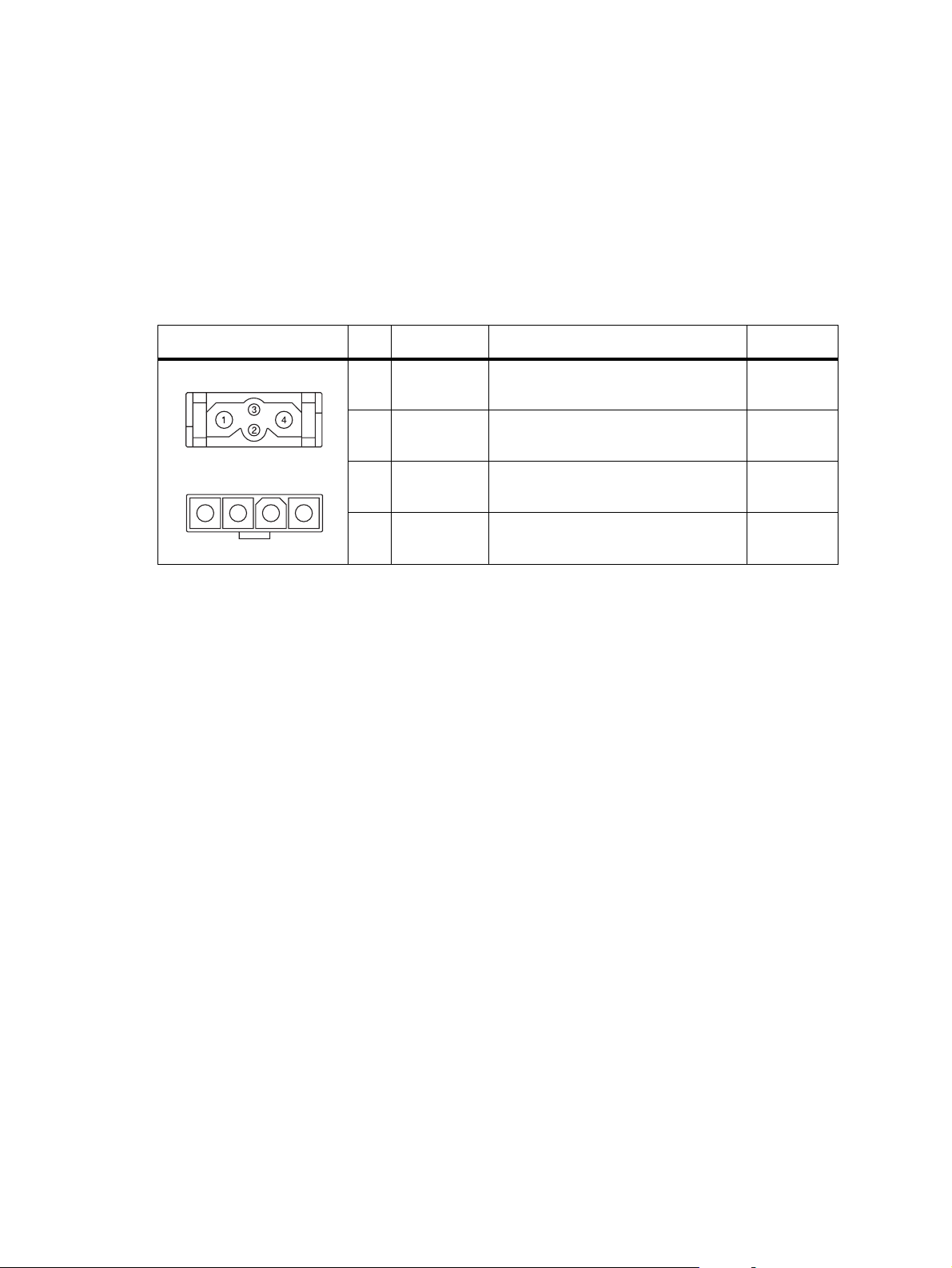
Table 3.3 Radio body power connector— pins and signals
Pinout Pin Signal name Description Signal type
>25W radio
rear view
25W radio
1 2 3 4
rear view
Selecting the Power
Source
1 AGND Earth return for radio body power
source
2 SPK– External speaker output. Balanced load
configuration
3 SPK+ External speaker output. Balanced load
configuration
4 13V8 BATT DC power input for radio body and
control head
Ground
Analog
Analog
Power
Notice Each radio is designed to operate from a nominal 12V negative
ground supply. Each radio may draw up to 15A of current. Each radio
will tolerate a supply voltage range of 10.8V to 16.0 V at the radio.
In passenger vehicles, the radio is always connected directly to the battery
using the power cable provided.
Notice Do not connect the radio to the center tap of two 12V batteries! This may result in damage to the radio due to earth loops, in particular when the negative lead is disconnected from the vehicle battery.
It may also result in overcharging or undercharging of the batteries,
reducing their service life.
In trucks, where direct connection to the battery is often not possible, each
radio can be connected to a suitable terminal inside the fuse box that is
connected directly to the battery.
24V-to-12V
Converter
In vehicles with a supply voltage larger than 16.0V, such as many trucks, it
is essential to provide a suitably rated 24V-to-12V converter. This will
isolate the radios from excessive battery voltage and provide the correct DC
operating conditions. Note that most 24 V-to-12V converters already fitted
are not rated sufficiently.
TM8260 Installation and Programming Guide Installing a Dual-Radio System 27
© Tait Limited October 2014
Page 28

Standby Current
When using the ignition signal to turn off the radio system, the standby
current is reduced to <6mA. For detailed stand-by figures, see Table 3.4 on
page 28.
Table 3.4 Current drain for the various radio systems
Radio System
type
Dual body,
single head
Dual body,
dual head
Connecting the
Power Cable
Completely off
(e.g. off via
ignition sense)
<6mA approx. 60mA approx. 240mA approx. 310mA
<6mA approx. 60mA approx. 300mA approx. 425mA
Stand-by (e.g. off
via on/off key)
Notice Although it is possible to connect the radio system in line with
the vehicle ignition, this is not recommended, as it may draw too much
current and damage the vehicle wiring and steering column or ignition
switch. This may also cause the supply voltage of the radio to drop below
the specified level.
On (no backlight)
but not
transmitting or
receiving
On (maximum
backlighting)
Notice Disconnecting the vehicle’s battery may cause problems with
some electronic equipment, such as vehicle alarms, engine management
systems, and in-car entertainment systems. Check that the vehicle owner
has the necessary information to make all electronic equipment function
correctly after battery reconnection.
Notice If the battery is not disconnected, exercise extreme caution
during the installation and install the fuses only when the installation is
ready to be checked. For more information, refer to “Checking the
Installation” on page 36.
1. Disconnect the vehicle’s battery unless specifically prohibited from
doing so by the customer, vehicle manufacturer, agent, or supplier.
Notice Route the cables in a manner that minimizes coupling of electric vehicle systems such as alternators into the radio.
Notice Protect the power cables from engine heat, sharp edges and
from being pinched or crushed.
2. Run the power cable between one radio’s mounting position and the
power source and cut it to length, allowing approximately 20 cm
(8 in.) excess at the radio end.
3. Plug the power cable into the power connector of the radio.
28 Installing a Dual-Radio System TM8260 Installation and Programming Guide
© Tait Limited October 2014
Page 29

Warning Danger of fire! The radio’s protection mechanisms
rely on the correct fuses on both the negative and positive power
supply leads being present. Failure to fit the correct fuses may
result in fire or damage to the radio.
The correct fuse types are:
■ >25W radios: 20A fuses (Tait IPN 265-00010-81)
>25W 25W
■ 25W radios: 10A fuses (Tait IPN 265-00010-80)
4. Cut the negative (black) and the positive (red) wires where the in-line
fuse holders will be placed (as close to the power source as possible).
Notice Do not install the fuses until the installation is ready to be
checked. For more information, refer to “Checking the Installation” on
page 36.
5. Insert each end of the negative wire into each of the fuse crimp-
terminals and crimp them to force the metal contacts onto the wires.
6. Push the two crimp-terminals into the clear plastic fuse cover. Close
the cover while the next steps are completed.
Power During Radio
Operation
7. Repeat steps 5 and 6 for the positive wire.
8. Connect the negative wire to the battery ground terminal.
9. Connect the positive wire to the battery positive terminal.
10. Repeat steps 2 to 9 for the other radio body.
Notice Do not install the fuses until the installation is ready to be
checked. For more information, refer to “Checking the Installation” on
page 36.
It is important that both radio bodies power on at the same time. If that does
not happen (for example, the Power On Mode is set to Power On in the
programming application and power is applied to each body in sequence)
you must turn the system off then on again via the on/off key. It is not
recommended that you remove or apply power to a single radio body while
operating the radio system.
If power to one radio body is disrupted, you must turn the system off then
on again via the on/off key. If there is no power supply to one radio body
after the radio system is switched on, the other body and control head will
continue to operate as a single radio unit.
Notice The ignition signal may fail to turn the remaining radio body
on and off if there is no power to one radio body. In this situation, the
on/off key must be used to continue operating the radio.
TM8260 Installation and Programming Guide Installing a Dual-Radio System 29
© Tait Limited October 2014
Page 30

3.7 Connecting Remote Speakers
You must connect remote speakers to the radio bodies if:
■ using a hand-held control head, or
■ using a control head with a graphical-display and you want to enhance
or replace the control head’s internal speaker.
The remote speaker will only sound audio from the radio that it is connected
to. Audio is never fed to a remote speaker from the other radio body. If a
radio is at the background and dual receive is activated, the attached remote
speaker will sound received audio from that radio at a reduced volume. If a
radio is at the foreground, the attached remote speaker will sound received
audio from that radio at normal volume, and audible indicators.
The following high-power remote speakers are recommended:
>25W
25W
■ TMAA10-06 high-power remote speaker for >25W radios
■ TMAA10-03 high-power remote speaker for 25W radios.
If a different speaker is used, receptacles for the speaker pins of the power
connector are provided with the installation kit. The installation kit also
contains a flying lead connector that, when installed, enables the speaker to
be easily removed and re-installed as required.
The speaker is connected to pins 2 (SPK–) and 3 (SPK+) of the power
connector. See Table 3.3 on page 27. For more information, refer to the
installation instructions provided with the speaker, or to the relevant section
of the service manual.
3.8 Installing a Cross-band Linking Cable
The TMAA04-04 or TMAA04-06 cross-band linking cable can be used to
extend the features available with TM8260 dual radio systems. The cables
connect to both radio’s auxiliary ports so the radio system can be used as a
cross-band repeater. The TMAA04-06 cable provides additional
connections to enable, for example, GPS operation and power via ignition
sense.
For cross-band pins and signals on the auxiliary connector, see Figure 3.9 on
page 31.
Notice The radio does not meet the IP54 protection standard once the
auxiliary connector rubber bungs have been removed and this cable has
been installed. Care must be taken when the radio is being operated in
an environment where there is water, dust or other
environmental hazards.
30 Installing a Dual-Radio System TM8260 Installation and Programming Guide
© Tait Limited October 2014
Page 31
To install the cable:
1. Remove the rubber bung that cover the auxiliary connector on each
radio body.
2. Plug an auxiliary connector into the auxiliary port of a radio body.
3. Plug the second auxiliary connector into the auxiliary port of the
other radio body.
The cable can be plugged in either way—its orientation has no impact
on radio performance. However, to reduce the cabling required, orient
the cable so other connectors from the cable (for example, the external
interface connector and GPS socket) are closest to the device or devices
to connect to.
4. Tightly fasten the jackscrew-type locks.
5. If your cable has additional connectors, refer to the installation
instructions for your cable (see “Associated Documentation” on
page 5), or contact your radio provider.
6. Enable the appropriate programmable I/O and external PTT 1
settings using the programming application. See “Crossband
Repeater Settings” on page 42.
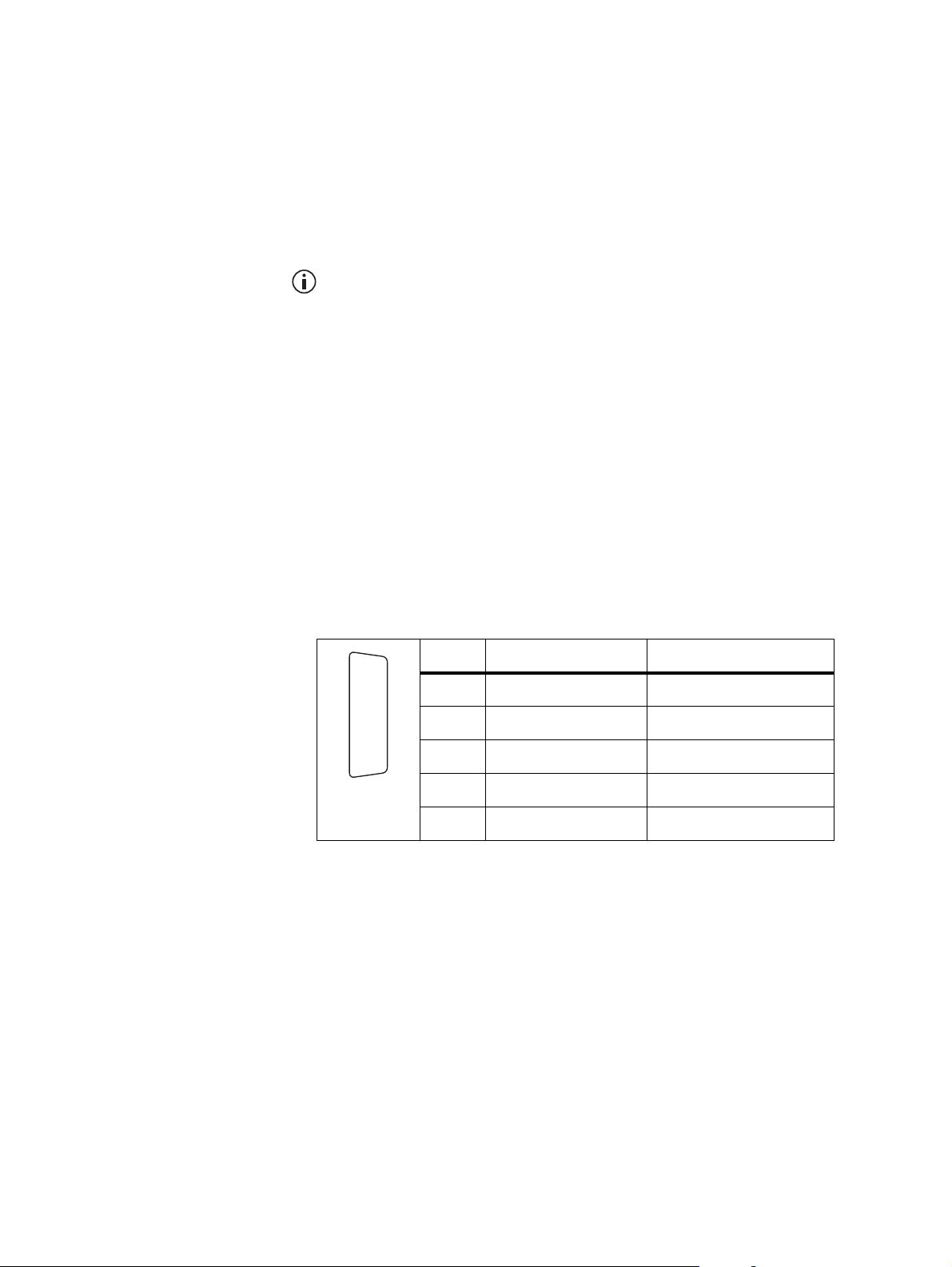
Figure 3.9 Auxiliary connectors— pins and signals for crossband repeater
operation
B
J
C
1)
D
1!
E
1@
F
1#
G
1$
H
1%
I
rear view
a. Your cable may have other pins not listed here that carry additional signals.
2 AUX_GPIO5 busy (output)
7 AUD_TAP_IN audio tap input
12 AUX_GPI1 PTT (input)
13 AUD_TAP_OUT audio tap output
15 AGND ground
a
Pin Signal name Description
TM8260 Installation and Programming Guide Installing a Dual-Radio System 31
© Tait Limited October 2014
Page 32
3.9 Installing the Control Head Solution
To install a single graphical-display control head, see “Installing a Graphical
Display Control-Head” below.
To install dual graphical display control-heads, follow the installation
instructions in the upgrade kit (see “Associated Documentation” on
page 5).
To install a hand-held control head, see “Installing a Hand-Held Control
Head” on page 35.
Installing a Graphical Display Control-Head
To install a single control head with graphical-display to dual radio bodies:
■ assemble the control-head interface
■ mount the control head using the U bracket, then
■ install the remote cable.
Assembling the
Control Head
Interface
The following steps show how to connect the control head remote interface
to the control head.
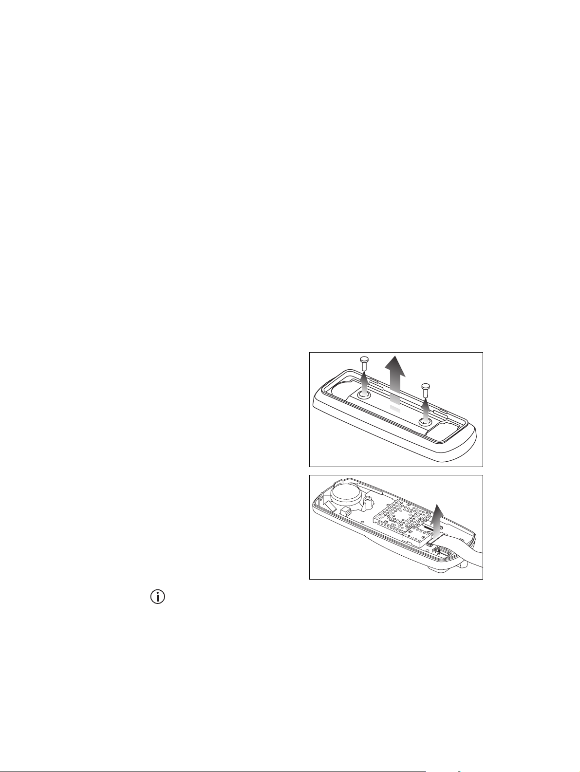
1. Undo the two Torx T20 screws on the adaptor flange of the control head, and remove
the adaptor flange.
2. Keep the two screws
for step 6.
3. Unplug the controlhead loom.
4. The adaptor flange and
control-head loom are
not used for the remote
control-head
installation.
You can change the control head orientation by changing the controlhead loom to the opposite connector. For more information, refer to the
remote control-head installation instructions (IPN 402-00020-xx, available from http://support.taitradio.com).
32 Installing a Dual-Radio System TM8260 Installation and Programming Guide
© Tait Limited October 2014
Page 33
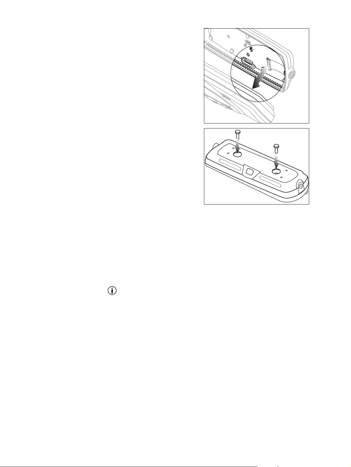
5. Plug the control-head
interface loom into the
connector on the
control head.
6. Use the two Torx T-20
screws from the first
step to fit the controlhead remote interface
to the control head.
Mounting the
Control Head
Notice When fitting the control-head interface to the control-head,
be careful not to damage the space-frame seal.
The remote U-bracket is used to install the remote control-head assembly
on the dashboard or on any sufficiently flat surface.
Notice Check that the remote U-bracket is not distorted when the
screws are tightened.
The screws provided are self-drilling. For more precise positioning, predrill ∅ 1/8 inch (3 mm) pilot holes for self-drilling screws. Reduce the
hole size in metal that is less than 1/32 inch (1mm) thick.
Notice Ensure that drilling at the selected points will not damage
existing wiring.
1. Drill any holes required for cables and install suitable grommets or
bushings in the holes.
2. Screw the remote U-bracket in the chosen mounting position using
the self-drilling screws provided. Use all four screws provided.
3. Place the control-head assembly in the remote U-bracket and
position it for a good viewing angle.
4. Screw the remote control-head assembly into position using the two
thumb screws provided.
TM8260 Installation and Programming Guide Installing a Dual-Radio System 33
© Tait Limited October 2014
Page 34
Installing the
Remote Cable
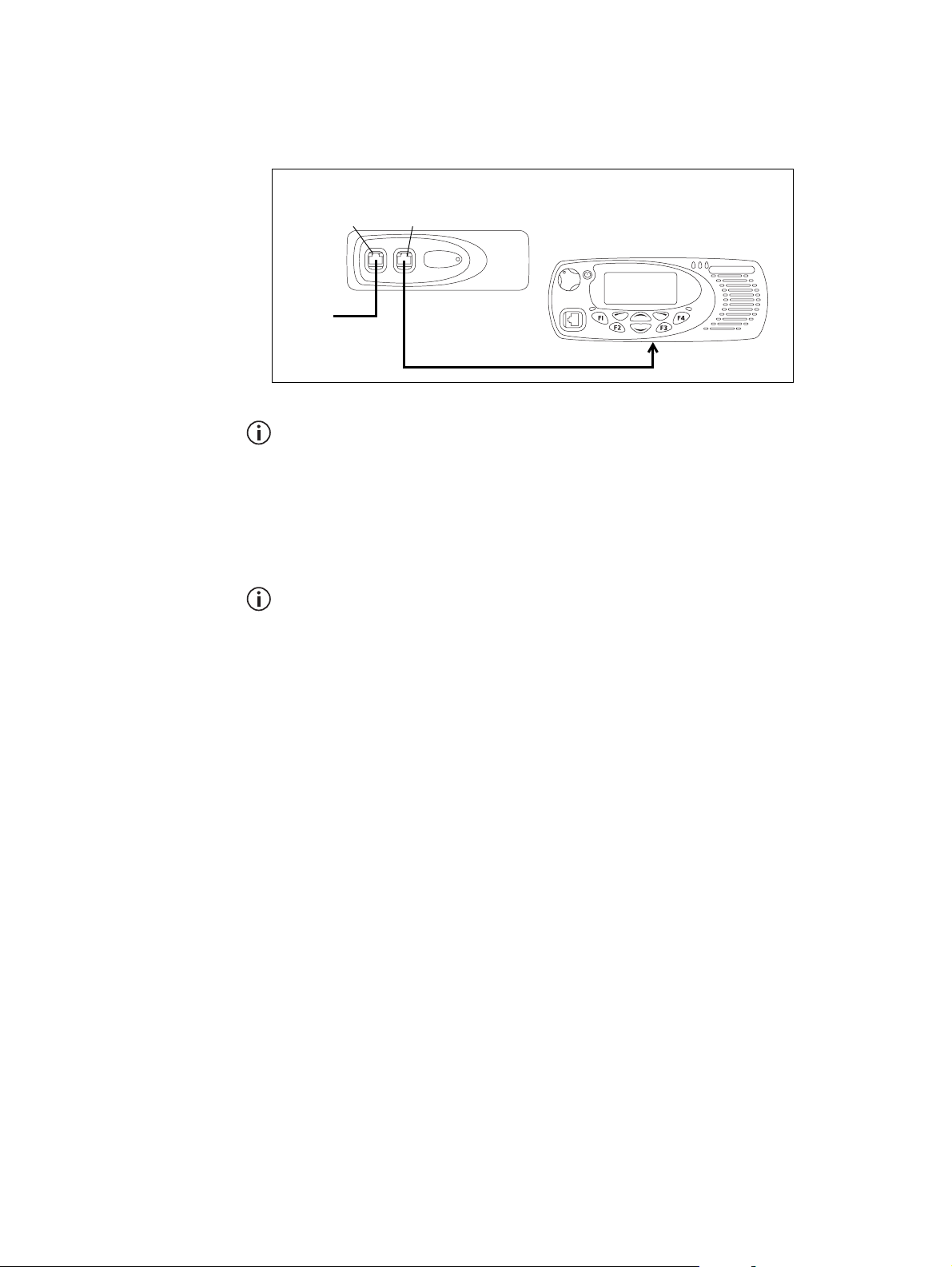
Figure 3.10 contains an overview of the connection between the radio
bodies and the control head.
Figure 3.10 Connecting radio bodies to control head with graphical-display
body with link J4 removed
outermost
port
to radio
body with
link J4 fitted
innermost
port
control head remote
cable TMAA04-01
(6m /19.6ft.)
control head
CH port
If a radio body does not have link J4 removed, or you cannot identify the
correct radio body to use, you will need to disassemble one or both interfaces. See “Removing the Body Interface” on page 22 for more infor-
mation.
1. Attach one end of the control-head remote cable to the innermost
port of the radio body with link J4 removed.
The outermost port of this radio body connects to the other radio body.
2. Attach the other end of the control-head remote cable to the rear port
of the control head remote interface.
3. Install the cable grommets. See “Removing and Installing
Grommets” on page 15.
34 Installing a Dual-Radio System TM8260 Installation and Programming Guide
© Tait Limited October 2014
Page 35
Installing a Hand-Held Control Head
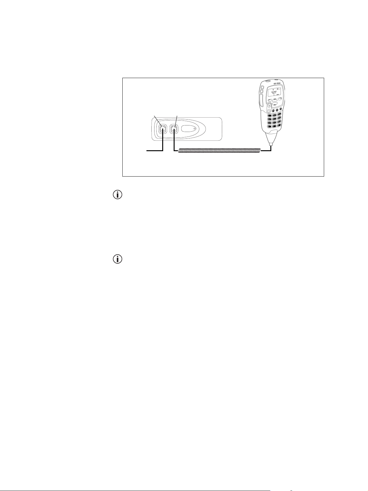
Figure 3.11 contains an overview of the connection between the radio
bodies and a hand-held control head.
Figure 3.11 Connecting radio bodies to hand-held control head
Body with link J4 removed
Outermost
port
To radio
body with
link J4 fitted
Innermost
port
Hand-held
control head
Hand-held control head curly cord
(may include extension TMAA04-14 to -17)
If a radio body does not have link J4 removed, or you cannot identify the
correct radio body to use, you will need to disassemble one or both interfaces. See “Removing the Body Interface” on page 22 for more information.
1. Attach the hand-held control head cord to the innermost port of the
radio body with link J4 removed.
The outermost port of this radio body connects to the other radio body.
2. Install the cable grommet. See “Removing and Installing Grommets”
on page 15.
3. Install the control head mounting clip in the most convenient
location for the radio user.
TM8260 Installation and Programming Guide Installing a Dual-Radio System 35
© Tait Limited October 2014
Page 36

3.10 Checking the Installation
Warning Danger of fire! The radio’s protection mechanisms
rely on the correct fuses on both the negative and positive power
supply leads being present. Failure to fit the correct fuses may
result in fire or damage to the radio.
The correct fuse types are:
■ >25W radios: 20A fuses (Tait IPN 265-00010-81)
>25W 25W
■ 25W radios: 10A fuses (Tait IPN 265-00010-80)
1. Insert the fuses into the power leads. The radio will turn on automatically at this point.
2. Switch the radio off then on again using the front panel control, but
do not transmit.
3. Connect an in-line power meter between one radio and its antenna.
4. Transmit and measure the forward and reflected power levels.
Less than 4% of the forward power should be reflected. If this is not
achieved, check the installation, including the antenna length.
5. Start reducing the length of the antenna in steps of 0.1 inches to
0.2 inches (2 to 5 mm). Measure the power levels at each step.
Notice Some antennas are pre-tuned and must not be cut. Check with
the manufacturers’ instructions.
6. Once the reflected power levels are within tolerance, repeat steps 3, 4
and 5 for the second radio.
7. Test the dual-radio functions.
■ Compare the receive functions (such as sensitivity) of one radio,
while the other radio is and is not transmitting. Ensure there is no
significant difference.
■ Compare the transmit functions (such as coverage) of one radio,
while the other radio is and is not transmitting.
■ Test all other functions, such as dual-receive and cross-band
repeater operation. Check that those functions operate as
expected.
If issues are found, move the radio bodies and/or antennas further
apart and re-test.
36 Installing a Dual-Radio System TM8260 Installation and Programming Guide
© Tait Limited October 2014
Page 37
4 Programming a Dual-Radio System
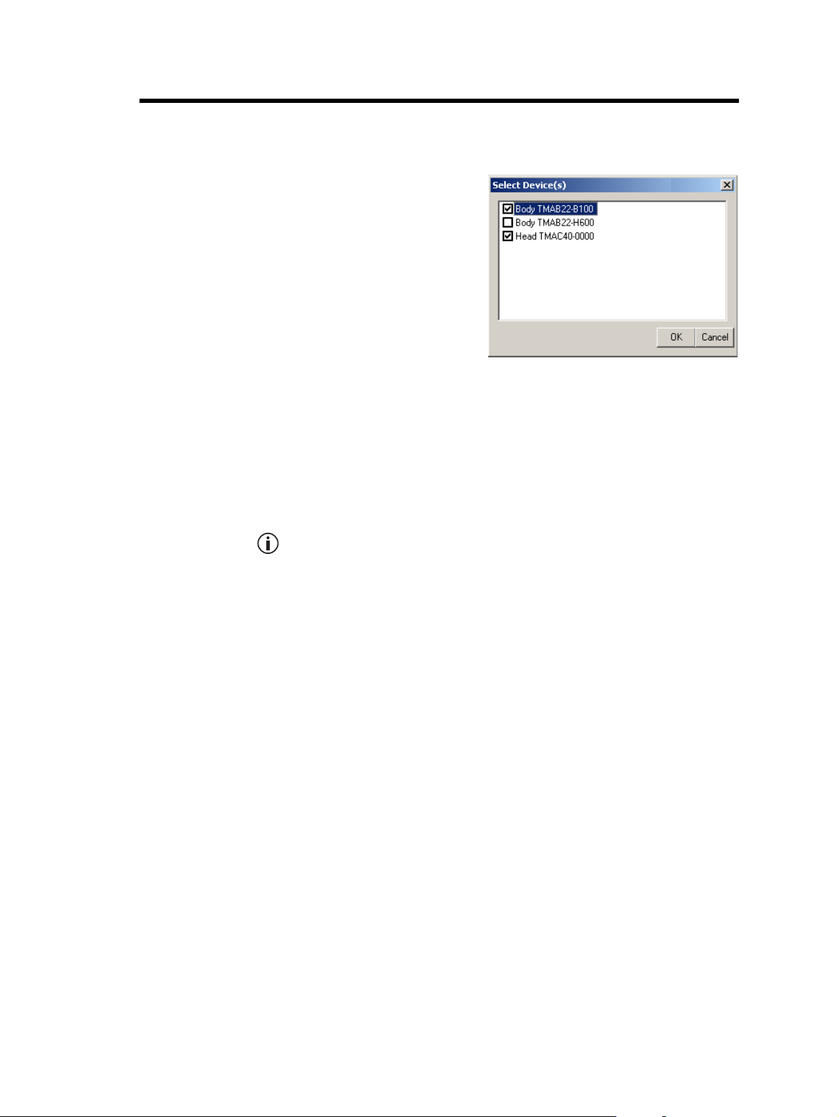
After you have downloaded
Figure 4.1 Select Device(s) dialog
NTIDs and assembled the
system, you can program or read
individual devices in the system.
Each time you attempt to
communicate with the radio
system, the Select Device(s)
dialog appears (an example is
shown in Figure 4.1).
This section contains the
following information:
■ Connecting a Dual-Radio System to a PC
■ Programming a Dual-Radio System
■ Recommended Dual-Radio Settings
■ Upgrading Radio Firmware
■ Calibrating a Dual-Radio System
■ Troubleshooting.
For required programming application and firmware versions for your
radio system, see “Hardware and Firmware Compatibility” on page 13.
TM8260 Installation and Programming Guide Programming a Dual-Radio System 37
© Tait Limited October 2014
Page 38

4.1 Connecting a Dual-Radio System to a PC
A dual radio system connects to a PC via the control head. The exact
connector to use depends on the control head solution.
Notice Do not attempt to connect the programming lead to an RJ45
socket on a radio body. This can cause damage to the connector and the
radio.
■ Single graphical-display control head: Unplug the standard or keypad
microphone, and connect a PC to the microphone port.
■ Hand-held control head: Use the tool provided in the TMAC70 kit or
an 8mm AF Allen key to remove the rear programming connector cover,
and connect a PC to the programming connector. For more
information, refer to the instructions provided with the hand-held
control head (see “Associated Documentation” on page 5).
■ Dual graphical-display control heads: As with the single graphical-display
control head, but using the microphone port of the primary control
head. To identify the primary control head, select Menu>Radio
settings>Radio info > Multi head info. For more information, refer to
the instructions provided with the upgrade kit (see “Associated
Documentation” on page 5).
4.2 Programming a Dual-Radio System
The following steps for programming a dual-radio system assume:
■ all the devices in the system have supported versions of firmware, and you
have installed supported versions of programming and calibration
software. See “Hardware and Firmware Compatibility” on page 13.
■ all the devices in the system have unique NTIDs assigned.
See “Downloading Configurations” on page 17.
■ all radio bodies in the system have the required software features enabled.
See “Checking the Required Firmware Versions and Software Features”
on page 17.
Step 1—
Create a template
file
1. Using the Programming Application, enter the information into the
fields that are common between the radios. See “Recommended
Dual-Radio Settings” on page 40.
2. Click File > Save.
3. Enter a descriptive name for the template, for example,
“TM8260_Master_File”.
38 Programming a Dual-Radio System TM8260 Installation and Programming Guide
© Tait Limited October 2014
Page 39

Step 2—
Program each
device in the system
1. Using the Programming Application, open the template file created
for the radio system.
2. Set the radio’s Band (Global > Specification form).
3. Enter a Radio Name (recommended).
The length of the radio name restricts the length of all channel and group
labels. Therefore a three-character radio name such as “UHF” or “VHF”
is recommended, as it will allow group and channel labels up to 10 characters (such as “Channel 99”).
4. Add all information relating to the band selected in step 2, including
channels (Conventional > Channel Setup > Channels form) and
groups (Scan Groups form).
5. Click File > Save As to save the device’s file to disk as a new file.
6. Click Radio > Program.
7. In the Select Device(s) dialog, select the radio body that matches the
Band selected in step 2, and optionally, the control head. See
Figure 4.1.
You cannot select more than one of the same device type (for example,
two radio bodies). The Select Device(s) dialog will automatically select
the radio body with the matching operating band (step 2).
The recommended sequence for programming a dual-radio system is a
radio body (TMABxx-) in the first session, then the other body
(TMABxx-) and the head (TMACxx-) together in the second session.
8. Repeat steps 1 to 7 and program the other radio body and the control
head.
TM8260 Installation and Programming Guide Programming a Dual-Radio System 39
© Tait Limited October 2014
Page 40

4.3 Recommended Dual-Radio Settings
The programming configuration of all devices must be as similar as possible,
with the exception of the operating band, radio name, channels and groups.
If features relating to the user interface (such as function keys, radio menus,
and backlighting), and other features like the security lock are different,
there may be unexpected behavior when powering on or switching between
the radios.
The following settings are recommended for a dual-radio system. Use this
table when setting up a template file, before programming the system (see
“Programming a Dual-Radio System” on page 38).
Table 4.1 Recommended dual-radio settings
Field/Feature Location Comments
Radio Name Global > Specifications form The radio name, if used, should be different for
both radio bodies in the system.
Power On Mode Global > Start-up form The power on mode must be the same for all
devices in the system.
Power-up on Last
Active Body
Reset on Error Global > Start-up form The Reset on Error check box must be the same
Security Lock on Power Up
and Security PIN
PTT fields Global > PTT form PTT settings for both radio bodies are used when
Startup (Channel or Group) Conventional >
Selcall Stun and Revive Conventional > Selcall >
Global > Start-up form This check box must be the same for all devices in
the system.
for all devices in the system.
Global > Start-up form If the security PIN is enabled, it must be enabled
(and have the same PIN) for all devices in the
system.
in dual-transmit mode and the radio user presses
the PTT. Care should be taken if programming PTT
behavior differently between the radio bodies. PTT
settings are typically set the same for all devices in
the system.
You can program this option for the foreground
Conventional UI form
Control Status form
radio (the radio body with the lowest NTID) to
start on a specific channel or group each time the
radio system is turned on. You can also program
this option for the background radio to default to
a specific channel or group after the radio system
is turned on, and the radio user subsequently
switches the active radio or enables dual receive.
Selcall stun and revive functionality is currently not
supported for TM8260 radio systems. If the stun
and revive control status types are used, set the
equivalent Rx Processing fields to No for all
devices.
40 Programming a Dual-Radio System TM8260 Installation and Programming Guide
© Tait Limited October 2014
Page 41

Table 4.1 Recommended dual-radio settings (Continued)
Field/Feature Location Comments
Conv Key Settings Conventional > Conv Key
Settings form
Dual body functionality such as dual transmit and
receive, and changing the foreground radio, can
only be accessed via function keys.
Add the Dual Body Mode and Single Body Mode
actions to separate keys, or Dual/Single Body
Mode to a single key.
Add the Switch Active Radio action to a different
function key.
Other Function Key Settings
and the Radio Menu
Left Selection Key and
Scroll Keys
Conventional >
Conventional Menu form
Conventional > Conv Key
Settings form
The radio’s function key settings and menu must
be the same for all devices in the system.
If options are programmed for the left selection
key and/or scroll keys, they must be the same for
all devices in the system.
UI Preferences and
Conventional UI
Global > UI Preferences
form, and
Conventional >
Conventional UI form
UI preferences must be configured identically for
all devices in the system. For example,
backlighting, keypress tones, the RSSI icon, and
the default dialling type.
Programmable I/O Programmable I/O form All radio body I/O pins are supported, and all
actions are supported except the output F1 to F4
Key Status. The control head I/O pin (CH_GPIO1) is
limited to outputs only, and those outputs will
always reflect the foreground radio.
The following actions are dependant on the
current mode, and state of the active radio body.
External PTT 1 and 2: The radio body that the
PTT is connected to will transmit, unless
transmission is invalid (for example, that radio is
the background radio in single-body mode).
Toggle F1 and F4 Key LED: The function key LED
will reflect the state of the relevant I/O pin on the
foreground radio.
Radio Ready: The radio at the background in
single-body mode is not considered ready, so will
not activate the output pin.
Note: A cross-band linking cable requires specific
programmable I/O settings for both radio bodies.
For more information, see “Crossband Repeater
Settings” on page 42.
Trunked MPT Trunked MPT settings are currently not supported
with TM8260 radio systems. Do not attempt to
program these fields or enable the optional
feature for MPT 1327 Trunking.
TM8260 Installation and Programming Guide Programming a Dual-Radio System 41
© Tait Limited October 2014
Page 42

4.4 Crossband Repeater Settings
The following settings are for cross-band repeater operation only. These
settings require a cross-band linking cable to be installed between the radio’s
auxiliary ports. For more information, see “Installing a Cross-band Linking
Cable” on page 30.
Your cable may have additional connections that require further programming (for example, GPS, ignition sense, and external alert). For
information on settings related to these additional connectors, refer to
the installation instructions for your cable (see “Associated Documenta-
tion” on page 5), or contact your radio provider.
Programmable I/O
and Audio Settings
Table 4.2 Cross-band settings in the Programmable I/O form, Digital tab
Pin Mode Direction Label Action Active Debounce
AUX_GPI1 Conventional Input XBAND_TX Crossband Tx Input Low 10
AUX_GPIO5 Conventional Output BUSY Busy Status
Table 4.3 Cross-band settings in the Programmable I/O form, Audio tab
Pin Tap In Tap In Type
Rx None A-Bypass In On PTT R7 D-Split
EPTT1 T5 A-Bypass In On PTT None C-Bypass 0ut On PTT
Notes: 1. Select Busy Status (Table 4.2) and Busy Detect (Table 4.3) to re-
At a minimum, settings in Table 4.2, Table 4.3, and Table 4.4 must be
programmed for both radios.
Tap I n
Unmute
1
Signalling Audio Mute
2
Status
Tap O ut
Tap O ut
Ty pe
3
Low None
Tap Out Unmute
Busy Detect
Busy Detect + Subaud
1
transmit any signal.
2
2. Select Signalling Audio Mute Status (Table 4.2) and Busy Detect +
Subaud (Table 4.3) to transmit valid signalling only. This is
recommended if the repeater is to operate on a scan group where
member channels require valid subaudible signalling. Otherwise the
radio may re-transmit short bursts of activity when a channel is busy
but not captured due to invalid activity.
3. D-Split means the receiving radio will sound the repeater audio. To
silence the repeater signal on the receiving radio, select C-Bypass
Out.
42 Programming a Dual-Radio System TM8260 Installation and Programming Guide
© Tait Limited October 2014
Page 43

Table 4.4 Cross-band settings in the PTT form, External PTT (1) tab
Field Setting
Advanced EPTT1 PTT Transmission Type Voice
Audio Source Audio Tap In
Receive and
Transmit Settings
The cross-band repeater receives signals based on the radio’s squelch (carrier)
mute, and re-transmits signals based on external PTT 1. If programmed to
only re-transmit valid signals, the radio’s signalling mutes are also taken into
account, which are affected by the radio’s monitor function (such as the
hookswitch monitor when the microphone is off the hook). If monitor
settings are programmed, the radio user must not enable monitor (such as
having the microphone off the hook) while entering, or during, cross-band
repeater mode.
The transmit timer, if enabled, limits the maximum duration of cross-band
repeater transmissions. If a transmit lockout period is programmed then
further repeater transmissions will also be inhibited until the lockout timer
expires. However, if a valid received signal is present when the lockout timer
expires then the radio does not automatically resume transmission.The
received signal must first drop and retur n before re-transmission resumes.
Priority scanning also affects the transmit timer during cross-band repeater
transmissions. If a non-priority channel in the group is captured, the radio
will re-transmit that activity and the transmit timer will begin counting
down. However, each time the radio samples the priority channel or
channels there is a brief break in reception, which will cause the transmit
timer to restart.
Squelch override is not compatible with cross-band repeater operation.
Avoid programming this feature to a function key, and consider removing
the menu option.
Transmit Inhibit If both radios are receiving activity when cross-band repeater mode is
activated, the radio system can rapidly cycle between transmit and receive.
Set Tx Inhibit to Busy to prevent this from happening by not allowing the
radio system to transmit when there is another busy signal. An alternative is
to set different debounce times for each radio (such as 10 and 100 ms),
which will separate each radio’s entry into cross-band repeater mode.
If the cross-band repeater is programmed to only re-transmit valid signals,
and one radio is receiving an invalid signal (such as invalid CTCSS), the
mute will stay closed and no re-transmission will occur. However, if the
other radio then receives a valid signal, the radio will attempt to re-broadcast
this over the other signal. Set Tx Inhibit to Busy or Mute to prevent this
re-transmission occurring.
TM8260 Installation and Programming Guide Programming a Dual-Radio System 43
© Tait Limited October 2014
Page 44

System Timing
For the cross-band repeater to operate correctly with other base stations or
repeaters, system timing must be taken into account. If using subaudible
signalling and the transmitter requires a “tail”, then this can be configured
according to Table 4.5. During the lead-out delay period, no signalling,
such as CTCSS or DCS, is present.
Table 4.5 Transmit tail in the Basic Settings form, Subaudible Signalling tab
Field Setting
CTCSS Settings Lead-Out Delay any duration, up to 1000ms
DCS Settings Lead-Out Delay any duration, up to 1000 ms
4.5 Upgrading Radio Firmware
The Tait Firmware Upgrade Tool (from the programming application, click
To o l s > Download) shows the NTID (network ID) for each device. When
reporting a radio system’s configuration, the table will list the various types
of firmware for all devices in the system.
Notice Reporting the configuration will also show SCT (System
Configuration Table) files for each device, which must exist for a radio
system. These files are the result of downloading configurations (see
“Downloading Configurations” on page 17). Do not attempt to delete
these files.
When you download firmware to hardware of a particular type (for example,
the target hardware shows as a radio body), it will be sent to all devices in
the system of the same hardware type. The firmware will be downloaded to
each device in sequence.
For more information, access the Help of the Tait Firmware Upgrade Tool
(Help menu).
4.6 Calibrating a Dual-Radio System
TM8260 dual radio systems do not support calibration of the radio system
as a whole. The system must first be disassembled to a single head / single
body configuration. If calibration is required after repair, the radio body
must be calibrated outside of the system before re-installation.
To disassemble the radio to a single head and body, see Figure 3.3 on page 19
and Figure 3.4 on page 20.
44 Programming a Dual-Radio System TM8260 Installation and Programming Guide
© Tait Limited October 2014
Page 45

4.7 Troubleshooting
If reporting the configuration shows only two devices when three are
expected, or the Select Device(s) dialog does not appear when reading or
programming the radio system:
■ Make sure all cables are connected correctly, and securely.
■ Make sure power is applied to both radio bodies.
■ One or more devices may not have the correct system configuration table
of NTIDs. Re-download the table to all devices in the system. See
“Downloading Configurations” on page 17.
If a “Duplicate NTIDs” message appears on the radio display, you must
uninstall the radio to a single-head single-body system and use the
programming application’s multiple device configuration utility to change
the NTIDs (click Tools > Download and then Device Configuration >
Advanced). For more information, see “Downloading Configurations” on
page 17.
If an “incorrect band” message appears when attempting to program a radio
body, the band of the selected device to program is different to the band
selected in the programming application. Either change the Band field on
the Specifications form, or select the matching radio body in the Select
Device(s) dialog.
If an “unlicensed feature” message appears in the programming application,
or the LEDs on one or both radio bodies flash on and off when powering
up the system, optional features (for example, Multi-Body Support) may not
be enabled. For more information, see “Checking the Required Firmware
Versions and Software Features” on page 17.
TM8260 Installation and Programming Guide Programming a Dual-Radio System 45
© Tait Limited October 2014
Page 46

5 Quick Reference
All components are present and are the correct
❏
versions of hardware and firmware.
The system configuration table is downloaded to
❏
the control head and radio bodies.
Link J4 is removed from the radio body connected
❏
to the control head.
The remote interfaces are installed on the radio
❏
bodies and control head.
For each body remote interface, the earthing tag
❏
is attached onto the radio chassis.
Antennas are connected to both radio bodies. See page 25.
❏
The cables are attached into the correct ports. See page 32.
❏
All grommets are installed. See page 15.
❏
There is a solid and secure power supply to both
❏
radio bodies.
See pages 11 to 13.
See “Downloading
Configurations” on page 17.
See “Removing Link J4” on
page 21.
See page 22 and page 32.
See page 22.
See page 25.
The correct fuses are fitted to the power supply
❏
leads.
The radio system is programmed so the user can
❏
access dual-radio features.
See page 36.
See “Programming a Dual-
Radio System” on page 38.
46 Quick Reference TM8260 Installation and Programming Guide
© Tait Limited October 2014
Page 47

Glossary
This glossary contains an alphabetical list of terms and abbreviations related
to dual-radio systems. For information about other radio terms, consult the
glossary provided with the relevant documentation.
background radio The radio in a dual-radio system that is not currently showing on the radio
display, or is showing in a smaller font.
control head The device in a radio system that provides the user-interface.
cross-band linking
cable
cross-band repeater A mode in a dual-radio system where the system receives on one radio, and
A cable that connects the auxiliary ports of the two radio bodies, and
enabled a dual-radio system to be used as a cross-band repeater.
immediately re-transmits that reception on the other radio.
device A component (control head or radio body) in a radio system. A device is
known as target hardware when upgrading radio firmware.
dual body mode The function on a dual-radio system that enables you to turn on dual receive
and dual transmit
dual head system Two control heads connected to a radio body.
dual-radio system A control head connected to two radio bodies.
dual receive A state in a dual-radio system where the system receives on both the
foreground radio and background radio simultaneously.
dual transmit A state in a dual-radio system where the system transmits on both the
foreground radio and background radio simultaneously. Dual transmit
includes dual receive.
foreground radio The radio in a dual-radio system that is currently showing on the radio
display, or showing in a larger font.
NTID The unique network identifier that is assigned to each device in a radio
system.
primary radio The radio body in a dual-radio system with the lowest NTID.
radio A radio body, when connected directly or indirectly with a control head.
TM8260 Installation and Programming Guide Glossary 47
© Tait Limited October 2014
Page 48

radio body
The device in a radio system that provides standalone transmit and receive
on a single operating band, and also other functionality such as digital
processing. Also known as a torso.
radio system See dual-radio system.
single body mode The function on a dual-radio system that enables you to return to single
receive and single transmit.
single receive and
single transmit
system
configuration table
A state in a dual-radio system where the system transmits and receives on the
foreground radio only.
The table that is downloaded to every device in a radio system. The table
contains information about the system, including all devices, device names,
NTIDs, and priorities.
48 Glossary TM8260 Installation and Programming Guide
© Tait Limited October 2014
Page 49

Tait Software License Agreement
This Software License Agreement ("Agreement") is between you (“Licensee”) and Tait
Limited (“Tait").
By using any of the Software items embedded
and pre-loaded in the related Tait Designated
Product, included on CD, downloaded from
the Tait website, or provided in any other form,
you agree to be bound by the terms of this
Agreement. If you do not agree to the terms of
this Agreement, do not install or use any of the
Software. If you install or use any of the Software, that will be deemed to be acceptance of
the terms of this Agreement.
For good and valuable consideration, the parties agree as follows:
Section 1 DEFINITIONS
“Confidential Information” means all or
any information supplied to or received by
Licensee from Tait, whether before or after
installation or use and whether directly or indirectly pertaining to the Software and Documentation supplied by Tait, including without
limitation all information relating to the Designated Products, hardware, software; copyright,
design registrations, trademarks; operations,
processes, and related business affairs of Tait;
and including any other goods or property supplied by Tait to Licensee pursuant to the terms
of this Agreement.
“Designated Products” means products
provided by Tait to Licensee with which or for
which the Software and Documentation is
licensed for use.
“Documentation” means product and software documentation that specifies technical
and performance features and capabilities; user,
operation, and training manuals for the Software; and all physical or electronic media upon
which such information is provided.
“Executable Code” means Software in a
form that can be run in a computer and typically refers to machine language, which is comprised of native instructions the computer carries out in hardware. Executable code may also
refer to programs written in interpreted languages that require additional software to actually execute.
“Intellectual Property Rights” and “Intellectual Property” mean the following or
their substantial equivalents or counterparts,
recognized by or through action before any
governmental authority in any jurisdiction
throughout the world and including, but not
limited to all rights in patents, patent applications, inventions, copyrights, trademarks, trade
secrets, trade names, and other proprietary
rights in or relating to the Software and Documentation; including any adaptations, corrections, de-compilations, disassemblies, emulations, enhancements fixes, modifications,
translations and updates to or derivative works
from, the Software or Documentation,
whether made by Tait or another party, or any
improvements that result fro m Tait processes or,
provision of information services.
“Licensee” means any individual or entity
that has accepted the terms of this License.
“Open Source Software” means software
with freely obtainable source code and license
for modification, or permission for free distribution.
“Open Source Software License” means
the terms or conditions under which the Open
Source Software is licensed.
“Person” means any individual, partnership,
corporation, association, joint stock company,
trust, joint venture, limited liability company,
governmental authority, sole proprietorship, or
other form of legal entity recognized by a governmental authority.
“Security Vulnerability” means any flaw or
weakness in system security procedures, design,
implementation, or internal controls that if
exercised (accidentally triggered or intentionally exploited) could result in a security breach
such that data is compromised, manipulated, or
stolen, or a system is damaged.
“Software” (i) means proprietary software in
executable code format, and adaptations, translations, de-compilations, disassemblies, emulations, or derivative works of such software; (ii)
means any modifications, enhancements, new
versions and new releases of the software provided by Tait; and (iii) may contain one or
more items of software owned by a third-party
supplier. The term "Software" does not include
any third-party software provided under separate license or not licensable under the terms of
this Agreement.
“Source Code” means software expressed in
human readable language necessary for understanding, maintaining, modifying, correcting,
and enhancing any software referred to in this
Agreement and includes all states of that software prior to its compilation into an executable programme.
“Tait” means Tait Limited and includes its
Affiliates.
Section 2 SCOPE
This Agreement contains the terms and conditions of the license Tait is providing to
Licensee, and of Licensee’s use of the Software
and Documentation. Tait and Licensee enter
into this Agreement in connection with Tait
delivery of certain proprietary Software and/or
products containing embedded or pre-loaded
proprietary Software.
Section 3 GRANT OF LICENSE
3.1. Subject to the provisions of this Agreement
and the payment of applicable license fees, Tait
grants to Licensee a personal, limited, nontransferable (except as permitted in Section 7),
TM8260 Installation and Programming Guide Tait Software License Agreement 49
© Tait Limited October 2014
Page 50

and non-exclusive license to use the Software
in executable code form, and the Documentation, solely in connection with Licensee's use
of the Designated Products for the useful life of
the Designated Products. This Agreement does
not grant any rights to source code.
3.2. If the Software licensed under this Agreement contains or is derived from Open Source
Software, the terms and conditions governing
the use of such Open Source Software are in
the Open Source Software Licenses of the
copyright owner and not in this Agreement. If
there is a conflict between the terms and conditions of this Agreement and the terms and
conditions of the any applicable Open Source
Software Licenses, the terms and conditions of
the Open Source Software Licenses will take
precedence. For information about Open
Source Components contained in Tait products
and the related Open Source licenses, see:
http://support.taitradio.com/go/opensource
Section 4 LIMITATIONS ON USE
4.1. Licensee may use the Software only for
Licensee's internal business purposes and only
in accordance with the Documentation. Any
other use of the Software is strictly prohibited.
Without limiting the general nature of these
restrictions, Licensee will not make the Software available for use by third parties on a "time
sharing," "application service provider," "service bureau" basis, or for any other similar
commercial rental or sharing arrangement.
4.2. Licensee will not, and will not directly or
indirectly allow or enable any third party to: (i)
reverse engineer, disassemble, extract components, decompile, reprogram, or otherwise
reduce the Software or any portion thereof to a
human perceptible form or otherwise attempt
to recreate the source code; (ii) modify, adapt,
create derivative works of, or merge the Software; (iii) copy, reproduce, distribute, lend, or
lease the Software or Documentation to any
third party; (iv) grant any sublicense or other
rights in the Software or Documentation to any
third party; (v) take any action that would cause
the Software or Documentation to be placed in
the public domain; (vi) remove, or in any way
alter or obscure any copyright notice or other
notice of Tait or third-party licensor’s proprietary rights; (vii) provide, copy, transmit, disclose, divulge or make the Software or Documentation available to, or permit the use of the
Software by, any third party or on any machine
except as expressly authorized by this Agreement; or (viii) use, or permit the use of, the
Software in a manner that would result in the
production of a copy of the Software by any
means whatsoever other than what is permitted
in this Agreement. Licensee may make one
copy of the Software to be used solely for archival, back-up, or disaster recovery purposes;
provided that Licensee may not operate that
copy of the Software at the same time as the
original Software is being operated. Licensee
may make as many copies of the Documentation as it may reasonably require for the internal
use of the Software.
4.3. Unless otherwise authorized by Tait in
writing, Licensee will not, and will not enable
or allow any third party to: (i) install a copy of
the Software on more than one unit of a Designated Product; or (ii) copy or transfer Software installed on one unit of a Designated
Product to any other device. Licensee may
temporarily transfer Software installed on a
Designated Product to another device if the
Designated Product is inoperable or malfunctioning. Temporary transfer of the Software to
another device must be discontinued when the
original Designated Product is returned to
operation and the Software must be removed
from the other device.
4.4. Licensee will maintain, during the term of
this Agreement and for a period of two years
thereafter, accurate records relating to this
license grant to verify compliance with this
Agreement. Tait, or a third party nominated by
Tait, may inspect Licensee’s premises, books
and records, upon reasonable prior notice to
Licensee, during Licensee’s normal business
hours and subject to Licensee's facility and
security regulations. Tait is responsible for the
payment of all expenses and costs of the inspection, provided that Licensee shall indemnify
Tait for all costs (including audit costs and legal
costs on a solicitor client basis) if Licensee has
breached the terms of this Agreement. Any
information obtained by Tait during the course
of the inspection will be kept in strict confidence by Tait and used solely for the purpose
of verifying Licensee's compliance with the
terms of this Agreement.
Section 5 OWNERSHIP AND TITLE
Tait, its licensors, and its suppliers retain all of
their Intellectual Property Rights in and to the
Software and Documentation, in any form. No
rights are granted to Licensee under this Agreement by implication, estoppel or otherwise,
except for those rights which are expressly
granted to Licensee in this Agreement. All
Intellectual Property developed, originated, or
prepared by Tait in connection with providing
the Software, Designated Products, Documentation, or related services, remains vested
exclusively in Tait, and Licensee will not have
any shared development or other Intellectual
Property Rights.
Section 6 LIMITED WARRANTY;
DISCLAIMER OF WARRANTY
6.1. The commencement date and the term of
the Software warranty will be a period of one
(1) year from Tait shipment of the Software. If
Licensee is not in breach of any obligations
under this Agreement, Tait warrants that the
unmodified Software, when used properly and
in accordance with the Documentation and
this Agreement, will be free from a reproducible defect that eliminates the functionality or
successful operation of a feature critical to the
primary functionality or successful operation of
the Software. Whether a defect has occurred
will be determined solely by Tait. Tait does not
warrant that Licensee’s use of the Software or
50 Tait Software License Agreement TM8260 Installation and Programming Guide
© Tait Limited October 2014
Page 51

the Designated Products will be uninterrupted,
error-free, completely free of Security Vulnerabilities, or that the Software or the Designated
Products will meet Licensee’s particular
requirements. Tait makes no representations or
warranties with respect to any third-party software included in the Software.
6.2 Tait sole obligation to Licensee, and
Licensee’s exclusive remedy under this warranty, is to use reasonable efforts to remedy any
material Software defect covered by this warranty. These efforts will involve either replacing
the media or attempting to correct significant,
demonstrable program or documentation
errors or Security Vulnerabilities. If Tait cannot
correct the defect within a reasonable time,
then at Tait option, Tait will replace the defective Software with functionally equivalent Software, license to Licensee substitute Software
which will accomplish the same objective, or
terminate the license and refund Licensee’s paid
license fee. If Tait investigation of the perceived
defect reveals that no such defect in fact exists,
Tait may recover its costs in respect of such
investigation from Licensee.
6.3. Tait disclaims any and all other warranties
relating to the Software or Documentation
other than the express warranties set forth in
this Section 6. Warranties in Section 6 are in
lieu of all other warranties whether express or
implied, oral or written, and including without
limitation any and all implied warranties of
condition, title, non-infringement, merchantability, or fitness for a particular purpose or use
by Licensee (whether Tait knows, has reason to
know, has been advised of, or is otherwise
aware of any such purpose or use), whether
arising by law, by reason of custom or usage of
trade, or by course of dealing. In addition, Tait
disclaims any warranty to any person other than
Licensee with respect to the Software or Documentation.
Section 7 TRANSFERS
7.1. Licensee will not transfer the Software or
Documentation to any third party without specific prior written consent from Tait. Tait may
withhold such consent or at its own discretion
make the consent conditional upon the transferee paying applicable license fees and agreeing
to be bound by this Agreement.
7.2. In the case of a value-added reseller or distributor of Tait Designated Products, the consent referred to in Section 7.1 may be contained in a Tait Reseller or Tait Distributor
Agreement.
7.3. If the Designated Products are Tait vehiclemounted mobile products or hand-carried
portable radio products and Licensee transfers
ownership of the Tait mobile or portable radio
products to a third party, Licensee may assign its
right to use the Software which is embedded in
or furnished for use with the radio products
and the related Documentation; provided that
Licensee transfers all copies of the Software and
Documentation to the transferee.
7.4. For the avoidance of any doubt, Section
7.3 excludes TaitNet Infrastructure, or the
products listed at any time under network
products at: http://www.taitradio.com.
7.5. If Licensee, as a contractor or subcontractor (integrator), is purchasing Tait Designated
Products and licensing Software not for its own
internal use but for end use only by a Customer, the Licensee may transfer such Software,
but only if a) Licensee transfers all copies of
such Software and the related Documentation
to the transferee and b) Licensee has first
obtained from its Customer (and, if Licensee is
acting as a subcontractor, from the interim
transferee(s) and from the ultimate end user sub
license) an enforceable sublicense agreement
that prohibits any other transfer and that contains restrictions substantially identical to the
terms set forth in this Software License Agreement. Except as stated in the foregoing,
Licensee and any transferee(s) authorised by
this Section may not otherwise transfer or make
available any Tait Software to any third party
nor permit any party to do so. Licensee will, on
request, make available evidence reasonably satisfactory to Tait demonstrating compliance
with all the foregoing.
Section 8 TERM AND TERMINATION
8.1. Licensee’s right to use the Software and
Documentation will commence when the
Designated Products are supplied by Tait to
Licensee and will continue for the life of the
Designated Products with which or for which
the Software and Documentation are supplied,
unless Licensee breaches this Agreement, in
which case this Agreement and Licensee's right
to use the Software and Documentation may
be terminated immediately upon notice by
Tait.
8.2. Within thirty (30) days after termination of
this Agreement, Licensee must certify in writing to Tait that all copies of the Software have
been removed or deleted from the Designated
Products and that all copies of the Software and
Documentation have been returned to Tait or
destroyed by Licensee and are no longer in use
by Licensee.
8.3. Licensee acknowledges that Tait made a
considerable investment of resources in the
development, marketing, and distribution of
the Software and Documentation and that
Licensee's breach of this Agreement will result
in irreparable harm to Tait for which monetary
damages would be inadequate. If Licensee
breaches this Agreement, Tait may terminate
this Agreement and be entitled to all available
remedies at law or in equity including immediate injunctive relief and repossession of all nonembedded Software and associated Documentation. Licensee shall pay all Tait costs (on an
indemnity basis) for the enforcement of the
terms of this Agreement.
Section 9 CONFIDENTIALITY
Licensee acknowledges that the Software and
Documentation contain proprietary and Confidential Information valuable to Tait and are
Tait trade secrets, and Licensee agrees to respect
the confidentiality of the information con-
TM8260 Installation and Programming Guide Tait Software License Agreement 51
© Tait Limited October 2014
Page 52

tained in the Software and Documentation.
Section 10 LIMITATION OF LIABILITY
10.1. In no circumstances shall Tait be under
any liability to Licensee, or any other person
whatsoever, whether in Tort (including negligence), Contract (except as expressly provided
in this Agreement), Equity, under any Statute,
or otherwise at law for any losses or damages
whether general, special, exemplary, punitive,
direct, indirect, or consequential arising out of
or in connection with any use or inability of
using the Software.
10.2. Licensee’s sole remedy against Tait will be
limited to breach of contract and Tait sole and
total liability for any such claim shall be limited
at the option of Tait to the repair or replacement of the Software or the refund of the purchase price of the Software.
Section 11 GENERAL
11.1. COPYRIGHT NOTICES. The existence of a copyright notice on the Software will
not be construed as an admission or presumption of publication of the Software or public
disclosure of any trade secrets associated with
the Software.
11.2. COMPLIANCE WITH LAWS.
Licensee acknowledges that the Software may
be subject to the laws and regulations of the
jurisdiction covering the supply of the Designated Products and will comply with all applicable laws and regulations, including export
laws and regulations, of that country.
11.3. ASSIGNMENTS AND SUBCONTRACTING. Tait may assign its rights or subcontract its obligations under this Agreement,
or encumber or sell its rights in any Software,
without prior notice to, or consent of,
Licensee.
11.4. GOVERNING LAW. This Agreement
shall be subject to and construed in accordance
with New Zealand law and disputes between
the parties concerning the provisions hereof
shall be determined by the New Zealand
Courts of Law. Provided however Tait may at
its election bring proceedings for breach of the
terms hereof or for the enforcement of any
judgment in relation to a breach of the terms
hereof in any jurisdiction Tait considers fit for
the purpose of ensuring compliance with the
terms hereof or obtaining relief for breach of
the terms hereof.
11.5. THIRD-PARTY BENEFICIARIES.
This Agreement is entered into solely for the
benefit of Tait and Licensee. No third party has
the right to make any claim or assert any right
under this Agreement, and no third party is
deemed a beneficiary of this Agreement. Notwithstanding the foregoing, any licensor or
supplier of third-party software included in the
Software will be a direct and intended thirdparty beneficiary of this Agreement.
11.6. SURVIVAL. Sections 4, 5, 6.3, 7, 8, 9,
10, and 11 survive the termination of this
Agreement.
11.7. ORDER OF PRECEDENCE. In the
event of inconsistencies between this Agree-
ment and any other Agreement between the
parties, the parties agree that, with respect to
the specific subject matter of this Agreement,
this Agreement prevails.
11.8. SECURITY. Tait uses reasonable means
in the design and writing of its own Software
and the acquisition of third-party Software in
order to limit Security Vulnerabilities. While
no software can be guaranteed to be free from
Security Vulnerabilities, if a Security Vulnerability is discovered, Tait will take the steps specified in Section 6 of this Agreement.
11.9. EXPORT. Licensee will not transfer,
directly or indirectly, any Designated Product,
Documentation or Software furnished hereunder or the direct product of such Documentation or Software to any country for which New
Zealand or any other applicable country
requires an export license or other governmental approval without first obtaining such license
or approval.
11.10. SEVERABILITY. In the event that any
part or parts of this Agreement shall be held
illegal or null and void by any court or administrative body of competent jurisdiction, such
determination shall not affect the remaining
terms which shall remain in full force and effect
as if such part or parts held to be illegal or void
had not been included in this Agreement. Tait
may replace the invalid or unenforceable provision with a valid and enforceable provision that
achieves the original intent and economic
effect of this Agreement.
11.11. CONSUMER GUARANTEES.
Licensee acknowledges that the licenses supplied in terms of this agreement are supplied to
Licensee in business, and that the guarantees
and other provisions of prevailing consumer
protection legislation shall not apply.
11.12. WHOLE AGREEMENT. Licensee
acknowledges that it has read this Agreement,
understands it and agrees to be bound by its
terms and conditions. Licensee also agrees that,
subject only to the express terms of any other
agreement between Tait and Licensee to the
contrary, this is the complete and exclusive
statement of the Agreement between it and
Tait in relation to the Software. This Agreement supersedes any proposal or prior agreement, oral or written, and any other communications between Licensee and Tait relating to
the Software and the Designated Products.
52 Tait Software License Agreement TM8260 Installation and Programming Guide
© Tait Limited October 2014
 Loading...