


TM8100 mobiles
TM8200 mobiles
Service Manual
MMA-00005-05
Issue 5
November 2007

2 TM8100/TM8200 Service Manual
© Tait Electronics Limited November 2007
Contact Information
Tait Radio Communications
Corporate Head Office
Tait Electronics Limited
P
.O. Box 1645
Christchurch
New Zealand
For the address and telephone number of regional
offices, refer to the TaitWorld website:
We b si t e : ww
w.taitworld.com
Technical Support
For assistance with specific technical issues, contact
Technical Support:
E-mail: support@taitworld.com
We b si t e : www.taitworld.com/technical
Copyright and Trademarks
All information contained in this document is the
property of Tait Electronics Limited. All rights reserved.
This document may not, in whole or in part, be copied,
photocopied, reproduced, translated, stored, or reduced
to any electronic medium or machine-readable form,
without prior written permission from Tait Electronics
Limited.
The word TAIT and the TAIT logo are trademarks of
T
ait Electronics Limited.
All trade names referenced are the service mark,
trade
mark or registered trademark of the respective
manufacturers.
Disclaimer
There are no warranties extended or granted by this
document. Tait Electronics Limited accepts no
responsibility for damage arising from use of the
information contained in the document or of the
equipment and software it describes. It is the
responsibility of the user to ensure that use of such
information, equipment and software complies with the
laws, rules and regulations of the applicable
jurisdictions.
Enquiries and Comments
If you have any enquiries regarding this document, or
any comments, suggestions and notifications of errors,
please contact Technical Support.
Updates of Manual and Equipment
In the interests of improving the performance, reliability
or servicing of the equipment, Tait Electronics Limited
reserves the right to update the equipment or this
document or both without prior notice.
Intellectual Property Rights
This product may be protected by one or more patents
of Tait Electronics Limited together with their
international equivalents, pending patent applications
and registered trade marks: NZ338097, NZ508054,
NZ508340, NZ508806, NZ508807, NZ509242,
NZ509640, NZ509959, NZ510496, NZ511155,
NZ511421, NZ516280/519742, NZ519118,
NZ519344, NZ520650/537902, NZ522236,
NZ524369, NZ524378, NZ524509, NZ524537,
NZ524630, NZ530819, NZ534475, NZ534692,
NZ535471, NZ536945, NZ537434, NZ546295,
NZ547713, NZ521450, AU2003281447,
AU2002235062, AU2004216984, AU2005207405,
CA2439018, CA2554213, EU 03784706.8,
EU02701829.0, EU04714053.8, EU05704655.9,
GB23865476, GB2386010, GB2413249,
GB0516092.4, US11,232716, US10/597339, US10/
520827, US10/468740, US5,745,840, US10/547653,
US10/546696, US10/547964, US10/523952, US11/
572700.
To Our European Customers
Tait Electronics Limited is an
environmentally responsible company
which supports waste minimization and
material recovery. The European Union’s
Waste Electrical and Electronic Equipment
Directive requires that this product be disposed of
separately from the general waste stream when its
service life is over. Please be environmentally
responsible and dispose through the original supplier,
your local municipal waste “separate collection” service,
or contact Tait Electronics Limited.

TM8100/TM8200 Service Manual 3
© Tait Electronics Limited November 2007
Contents
Preface . . . . . . . . . . . . . . . . . . . . . . . . . . . . . . . . . . . . . . . . . . . . . . . . . 5
Scope of Manual . . . . . . . . . . . . . . . . . . . . . . . . . . . . . . . . . . . . . . . . . . . . 5
Hardware and Software Versions . . . . . . . . . . . . . . . . . . . . . . . . . . . . . . . . 5
Associated Documentation. . . . . . . . . . . . . . . . . . . . . . . . . . . . . . . . . . . . . 6
Publication Record . . . . . . . . . . . . . . . . . . . . . . . . . . . . . . . . . . . . . . . . . . 7
Alert Notices . . . . . . . . . . . . . . . . . . . . . . . . . . . . . . . . . . . . . . . . . . . . . .7
Abbreviations . . . . . . . . . . . . . . . . . . . . . . . . . . . . . . . . . . . . . . . . . . . . . . 8
Part A – Description of the Radio . . . . . . . . . . . . . . . . . . . . . . . . . . . . . . 11
1 Introduction. . . . . . . . . . . . . . . . . . . . . . . . . . . . . . . . . . . . . . . . . . . 13
2 Description . . . . . . . . . . . . . . . . . . . . . . . . . . . . . . . . . . . . . . . . . . . 21
3 Circuit Descriptions . . . . . . . . . . . . . . . . . . . . . . . . . . . . . . . . . . . . . 65
Part B – Servicing the Radio . . . . . . . . . . . . . . . . . . . . . . . . . . . . . . . . .103
4 General Information . . . . . . . . . . . . . . . . . . . . . . . . . . . . . . . . . . . . 107
5 Disassembly and Reassembly . . . . . . . . . . . . . . . . . . . . . . . . . . . . . . 135
6 Servicing Procedures . . . . . . . . . . . . . . . . . . . . . . . . . . . . . . . . . . . 155
7 Power Supply Fault Finding . . . . . . . . . . . . . . . . . . . . . . . . . . . . . . 169
8 Interface Fault Finding . . . . . . . . . . . . . . . . . . . . . . . . . . . . . . . . . . 179
9 Frequency Synthesizer Fault Finding . . . . . . . . . . . . . . . . . . . . . . . . 185
10 Receiver Fault Finding . . . . . . . . . . . . . . . . . . . . . . . . . . . . . . . . . . 247
11 Transmitter Fault Finding (>25W) . . . . . . . . . . . . . . . . . . . . . . . . . 267
12 Transmitter Fault Finding (25W) . . . . . . . . . . . . . . . . . . . . . . . . . . 341
13 CODEC and Audio Fault Finding. . . . . . . . . . . . . . . . . . . . . . . . . . 399
14 Fault Finding of Control Head with Graphical Display . . . . . . . . . . . 423
15 Fault Finding of Control Head with 1-, 2- or 3-Digit Display. . . . . . 447
16 Spare Parts . . . . . . . . . . . . . . . . . . . . . . . . . . . . . . . . . . . . . . . . . . . 455
Part C – Accessories . . . . . . . . . . . . . . . . . . . . . . . . . . . . . . . . . . . . . . .465
17 TMAA01-01 Line-Interface Board . . . . . . . . . . . . . . . . . . . . . . . . . 469
18 TMAA01-02 RS-232 Board . . . . . . . . . . . . . . . . . . . . . . . . . . . . . . 489
19 TMAA01-05 and TMAA01-07 Options Extender Boards . . . . . . . . 497
20 TMAA02-02 DTMF Microphone . . . . . . . . . . . . . . . . . . . . . . . . . 507
21 TMAA02-06 Support Kit for Concealed & Dynamic Microphones. . 511
22 TMAA02-07 Concealed Microphone . . . . . . . . . . . . . . . . . . . . . . . 519
23 TMAA02-08 Keypad Microphone . . . . . . . . . . . . . . . . . . . . . . . . . 521
24 TMAA03-02 Security Bracket . . . . . . . . . . . . . . . . . . . . . . . . . . . . 525
25 Installing a Remote Kit. . . . . . . . . . . . . . . . . . . . . . . . . . . . . . . . . . 529
26 Installing an Enhanced Remote Kit . . . . . . . . . . . . . . . . . . . . . . . . . 545
27 TMAA03-31 Control Head Interface Box . . . . . . . . . . . . . . . . . . . . 561

4 TM8100/TM8200 Service Manual
© Tait Electronics Limited November 2007
28 TMAA03-34 Extender Box . . . . . . . . . . . . . . . . . . . . . . . . . . . . . . 567
29 TMAA04-04 Crossband Linking Cable. . . . . . . . . . . . . . . . . . . . . . 573
30 TMAA04-05 Ignition Sense Kit . . . . . . . . . . . . . . . . . . . . . . . . . . . 579
31 TMAA04-06 Linking and Interface Cable . . . . . . . . . . . . . . . . . . . . 581
32 TMAA10-01 Desktop Microphone . . . . . . . . . . . . . . . . . . . . . . . . 589
33 TMAA10-02 Handset . . . . . . . . . . . . . . . . . . . . . . . . . . . . . . . . . . 593
34 TMAA10-03 and TMAA10-06 High-Power Remote Speakers . . . . 597
35 TMAA10-04 Remote PTT Kit and TMAA10-05 Hands-Free Kit . . 599
36 TMAA10-07 Desktop Microphone . . . . . . . . . . . . . . . . . . . . . . . . 607
37 TMAA10-08 Desktop Microphone . . . . . . . . . . . . . . . . . . . . . . . . 609
38 TOPA-SV-024 Test Unit. . . . . . . . . . . . . . . . . . . . . . . . . . . . . . . . 613

TM8100/TM8200 Service Manual 5
© Tait Electronics Limited November 2007
Preface
Scope of Manual
This manual contains information to service technicians for carrying out
level-1 and level-2 repairs of TM8100 and TM8200 radios and accessories.
Level-1 repairs entail the replacement of faulty parts and circuit boards;
level-2 repairs entail the repair of circuit boards, with the exception of
certain special items on the boards. The manual does not cover level-3
repairs, which entail the repair of the special items.
Hardware and Software Versions
This manual describes the following hardware and software versions.
The IPNs (internal part numbers) of the boards are listed below; the last two
digits in the IPN represent the issue of the board. The board information in
this manual covers all production-issue boards up to the issue listed below.
■ Main board (A4 band) 25W : 220-02074-04
■ Main board (B1 band) 25W : 220-01700-14
■ Main board (B1 band) 50W : 220-01723-04
■ Main board (C0 band) 25W : 220-01742-04
■ Main board (D1 band) 25W : 220-01717-02
■ Main board (H5 and H6 bands) 25W : 220-01697-11
■ Main board (K5 band) 30/35W : 220-02146-06
■ Main board (G2, H5 and H7 bands) 40W : 220-01722-04
■ Control-head board (1-digit display) : 220-02070-01
■ Control-head board (2-digit display) : 220-01699-03
■ Control-head board (3-digit display) : 220-02151-02
■ Control-head board (graphical display) : 220-01718-01
■ Control-head board (RJ45) : 220-01720-05
■ Programming application (TM8100) : version 3.02
■ Programming application (TM8200) : version 4.02
■ Calibration application : version 4.05

6 TM8100/TM8200 Service Manual
© Tait Electronics Limited November 2007
Associated Documentation
The following associated documentation is available for this product:
Manuals ■ MMA-00002-xx TM8100 User’s Guide
■ MMA-00003-xx TM8200 User’s Guide
■ MMA-00051-xx TM8235 User’s Guide
■ MMA-00028-xx TM8100/TM8200 Installation Guide
■ MMA-00006-xx TM8100 Operator’s Guide
■ MMA-00004-xx TM8200 Operator’s Guide
PCB Information ■ MMA-00016-xx TM8100/TM8200 Main Board A4 25W
■
MMAB12-B1-00-814
TM8100/TM8200 Main Board B1 25W
(board IPN 220-01700-05)
■ MMA-00031-xx TM8100/TM8200 Main Board B1 25W
(boards after IPN 220-01700-05)
■ MMA-00050-xx TM8100/TM8200 Main Board C0 25 W
■ MMA-00032-xx TM8100/TM8200 Main Board D1 25W
■
MMAB12-H5-00-814
TM8100/TM8200 Main Board H5/H6 25W
(board IPN 220-01697-05)
■ MMA-00033-xx TM8100/TM8200 Main Board H5/H6 25W
(boards after IPN 220-01697-05)
■ MMA-00069-xx TM8100/TM8200 Main Board K5 30/35W
■ MMA-00020-xx TM8100/TM8200 Main Board B1 50W
■ MMA-00021-xx TM8100/TM8200 Main Board G2/H5/H7 40W
■ MMA-00035-xx TM8100 Control-Head Board (2-Digit Display)
■ MMA-00036-xx TM8100 Control-Head Board (1-Digit Display)
■ MMA-00015-xx TM8200 Control-head Board (Graphical Display)
■ MMA-00058-xx TM8200 Control-Head Board (3-Digit Display)
■ MMA-00034-xx TM8200 Control-Head Board (RJ45)
■ MMA-00037-xx TM8100/TM8200 PCB Information
(printed, pre-punched and shrink wrapped;
comprises the latest releases of MMA-00015-xx,
MMA-00016-xx, MMA-00020-xx, MMA-00021xx, MMA-00031-xx, MMA-00032-xx,
MMA-00033-xx, MMA-00034-xx, MMA-00035xx, MMA-00050-xx, MMA-00058-xx, MMA00069-xx).
The characters xx represent the issue number of the documentation.
All available documentation is provided on the
TM8100/TM8200 Service CD, product code TMAA20-01.
Updates may also be published on the Tait support website.

TM8100/TM8200 Service Manual 7
© Tait Electronics Limited November 2007
3DK Manuals The following manuals are mainly of concern to third-party developers.
The manuals are supplied on the 3DK (third-party developer’s kit)
resource CD.
■ MMA-00011-xx TM8100/TM8200 3DK Hardware Developer’s
Kit Application Manual
■ MMA-00014-xx TMAA30-02 TM8000 3DK Application Board
Software Programmer’s Manual
■ MMA-00013-xx TMAA30-02 TM8000 3DK Application Board
Service Manual
■ MMA-00038-xx TM8100/TM8200 Computer-controlled Data
Interface Protocol Definition
Publication Record
Alert Notices
Within this manual, four types of alerts are given to the reader: warning,
caution, important and note. The following paragraphs illustrate each type
of alert and its associated symbol.
Warning!! This alert is used when there is a potential risk
of death or serious injury.
Caution This alert is used when there is the risk of minor or
moderate injury to people.
Important This alert is used to warn about the risk of equipment dam-
age or malfunction.
Issue Publication Date Description
01 March 2005 first release
02 May 2005 update for 40W/50W radios
03 August 2005 update to board issue 10 (B1, H5 and H6 bands)
of 25W radios, incorporation of accessories
manual
04 June 2006 include TM8200 3-digit-display control head, A4
and C0 bands, and information on issue -05 main
board for B1, H5 and H6 bands
05 November 2007 include G2 and K5 bands,
update product codes of control heads,
new space frame and speaker clamp for control
heads with 1-, 2- or 3-digit display

8 TM8100/TM8200 Service Manual
© Tait Electronics Limited November 2007
Note This alert is used to highlight information that is required to
ensure that procedures are performed correctly.
Abbreviations
Abbreviation Description
ACP Adjacent Channel Power
ADC Analog-to-Digital Converter
AGC Automatic Gain Control
ALC Automatic Level Control
ASC Accredited Service Centre
C4FM Compatible Four-level Frequency Modulation
CCTM Computer-Controlled Test Mode
CODEC Coder-Decoder
CSO Customer Service Organisation
CTCSS Continuous-Tone-Controlled Subaudible Signaling
DAC Digital-to-Analog Converter
DC Direct Current
DSP Digital Signal Processor
DTMF Dual-Tone Multi-Frequency
EPTT External PTT (Press-To-Talk)
ESD Electrostatic Discharge
FCL Frequency Control Loop
FE Front-End
FEC Forward Error Correction
FPGA Field-Programmable Gate Array
GPIO General Purpose Input/Output
GPS Global Positioning System
GUI Graphical User Interface
IC Integrated Circuit
IPN Internal Part Number
IF Intermediate Frequency

TM8100/TM8200 Service Manual 9
© Tait Electronics Limited November 2007
IQ In-Phase and Quadrature
ISC International Service Centre
LCD Liquid-Crystal Display
LED Light-Emitting Diode
LNA Low-Noise Amplifier
LO Local Oscillator
LPF Low-Pass Filter
NPN Negative-Positive-Negative
PA Power Amplifier
PCB Printed Circuit Board
PLL Phase-Locked Loop
PNP Positive-Negative-Positive
PSU Power Supply Unit
PTT Press-To-Talk
RISC Reduced Instruction Set Computing
RSSI Received Signal Strength Indication
SFE Software Feature Enabler
SMA Sub Miniature Version A
SMD Surface-Mount Device
SMT Surface-Mount Technology
SMPS Switch-Mode Power Supply
SPI Serial Peripheral Interface
TCXO Temperature-Compensated Crystal Oscillator
TEL Tait Electronics Limited
UHF Ultra High Frequency
VCO Voltage-Controlled Oscillator
VCXO Voltage-Controlled Crystal Oscillator
VHF Very High Frequency
Abbreviation Description

10 TM8100/TM8200 Service Manual
© Tait Electronics Limited November 2007

TM8100/TM8200 Service Manual 11
© Tait Electronics Limited November 2007
Part A – Description of the Radio
1 Introduction . . . . . . . . . . . . . . . . . . . . . . . . . . . . . . . . . . . . . . . . . . 13
1.1 Frequency Bands . . . . . . . . . . . . . . . . . . . . . . . . . . . . . . . . . . . . . . . . . . 15
1.2 RF Output Power. . . . . . . . . . . . . . . . . . . . . . . . . . . . . . . . . . . . . . . . . 15
1.3 Accessories . . . . . . . . . . . . . . . . . . . . . . . . . . . . . . . . . . . . . . . . . . . . . . 16
1.4 Product Codes . . . . . . . . . . . . . . . . . . . . . . . . . . . . . . . . . . . . . . . . . . . 17
1.5 Labels . . . . . . . . . . . . . . . . . . . . . . . . . . . . . . . . . . . . . . . . . . . . . . . . . . 19
1.6 Specifications . . . . . . . . . . . . . . . . . . . . . . . . . . . . . . . . . . . . . . . . . . . . 19
2 Description. . . . . . . . . . . . . . . . . . . . . . . . . . . . . . . . . . . . . . . . . . . 21
2.1 Mechanical Design . . . . . . . . . . . . . . . . . . . . . . . . . . . . . . . . . . . . . . . . 21
2.2 User Interfaces . . . . . . . . . . . . . . . . . . . . . . . . . . . . . . . . . . . . . . . . . . . 37
2.3 Connectors . . . . . . . . . . . . . . . . . . . . . . . . . . . . . . . . . . . . . . . . . . . . . . 38
2.4 Hardware and Software Architecture . . . . . . . . . . . . . . . . . . . . . . . . . . . 47
2.5 Operation in Receive Mode . . . . . . . . . . . . . . . . . . . . . . . . . . . . . . . . . 52
2.6 Operation in Transmit Mode . . . . . . . . . . . . . . . . . . . . . . . . . . . . . . . . . 57
3 Circuit Descriptions . . . . . . . . . . . . . . . . . . . . . . . . . . . . . . . . . . . . . 65
3.1 Transmitter Circuitry . . . . . . . . . . . . . . . . . . . . . . . . . . . . . . . . . . . . . . 67
3.2 Receiver Circuitry . . . . . . . . . . . . . . . . . . . . . . . . . . . . . . . . . . . . . . . . 70
3.3 Frequency Synthesizer Circuitry. . . . . . . . . . . . . . . . . . . . . . . . . . . . . . . 75
3.4 Frequency Control Loop . . . . . . . . . . . . . . . . . . . . . . . . . . . . . . . . . . . . 80
3.5 CODEC and Audio Circuitry . . . . . . . . . . . . . . . . . . . . . . . . . . . . . . . . 81
3.6 Power Supply Circuitry . . . . . . . . . . . . . . . . . . . . . . . . . . . . . . . . . . . . . 85
3.7 Interface Circuitry . . . . . . . . . . . . . . . . . . . . . . . . . . . . . . . . . . . . . . . . . 90
3.8 Digital Board . . . . . . . . . . . . . . . . . . . . . . . . . . . . . . . . . . . . . . . . . . . . 93
3.9 Control-Head Board with Graphical Display . . . . . . . . . . . . . . . . . . . . . 96
3.10 Control-Head Board with 1-, 2- or 3-Digit Display . . . . . . . . . . . . . . . . 99
3.11 RJ45 Control Head. . . . . . . . . . . . . . . . . . . . . . . . . . . . . . . . . . . . . . . 102

12 TM8100/TM8200 Service Manual
© Tait Electronics Limited November 2007
TM8100/TM8200 Service Manual Introduction 13
© Tait Electronics Limited November 2007
1 Introduction
The TM8100 and TM8200 series is a range of high-performance
microprocessor-controlled radios for analog voice and data communication.
The radios are designed for installation in vehicles but can also be used in
desktop, remote-monitoring and similar applications.
This manual includes the information required for servicing the radio and
its accessories.
This section describes the different options available for:
■ frequency bands
■ RF output power
■ accessories
■ product codes.
This section also gives an overview of the labels on the product and the
specifications.
Figure 1.1 TM8200 mobile radios
TM8235 radio with 3-digit-display control head
TM8250 or TM8255 radio with graphical-display control head
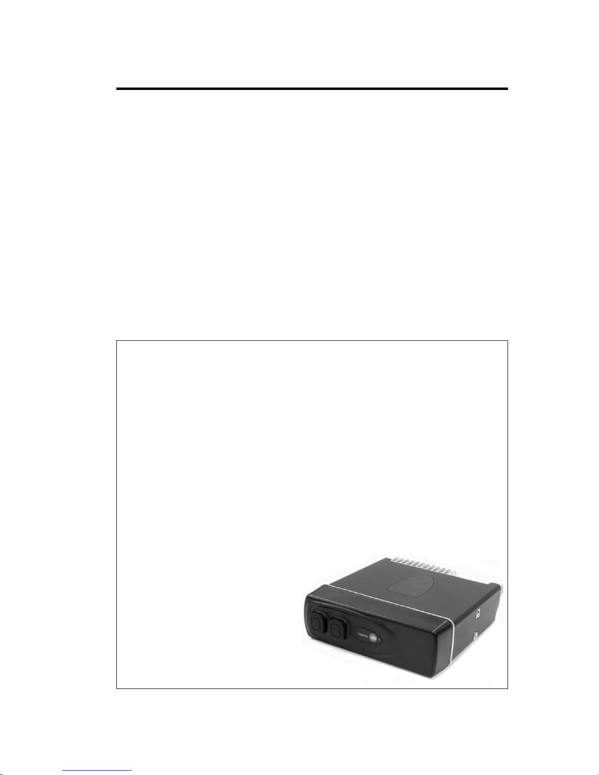
TM8252 radio with RJ45 control head

14 Introduction TM8100/TM8200 Service Manual
© Tait Electronics Limited November 2007
Figure 1.2 TM8100 mobile radios
rear view (25W radio)
TM8115 radio with 2-digit-display control head
TM8110 radio with 1-digit-display control head
TM8105 radio with blank control head

TM8100/TM8200 Service Manual Introduction 15
© Tait Electronics Limited November 2007
1.1 Frequency Bands
The radios are available in the following frequency bands:
■ 66 to 88MHz (A4)
■ 136 to 174MHz (B1)
■ 174 to 225MHz (C0)
■ 216 to 266MHz (D1)
■ 350 to 400MHz (G2)
■ 400 to 470MHz (H5)
■ 450 to 530MHz (H6)
■ 450 to 520MHz (H7)
■ 762 to 870MHz (K5 Tx)
762 to 776MHz and 850 to 870MHz (K5 Rx)
The frequency bands are implemented by different main boards in the radio
body. The control heads are identical for all frequency bands.
1.2 RF Output Power
The radio bodies are available with >25W and 25W RF output power.
The two RF output power options are implemented by different main
boards in the radio body, mechanically different radio bodies, and different
power connectors. The control heads are identical for all RF output
power options.
The >25W radio is available in the following frequency bands:
■ B1 (50W)
■ G2 (40W)
■ H5 (40W)
■ H7 (40W)
■ K5 (35W/30W)
The 25W radio is available in the following frequency bands:
■ A4
■ B1
■ C0
■ D1
■ H5
■ H6
>25W
25W

16 Introduction TM8100/TM8200 Service Manual
© Tait Electronics Limited November 2007
1.3 Accessories
Tait offers a large variety of audio accessories, installation kits, internal
options boards and other accessories such as a desktop power supply.
For more information on these accessories refer to “Part C – Accessories”
on page 465.
Audio Accessories The radios allow for the connection of a comprehensive range of audio
accessories:
■ rugged microphone (standard)
■ DTMF microphone
■ keypad microphone
■ handset
■ concealed microphone (TM8200) and concealed microphone kit
(TM8100)
■ high-power remote speaker
■ remote PTT kit and hands-free kit.
Installation Kits The radio is delivered with a vehicle installation kit, including a U-bracket.
Installation of the radio is described in the user’s guide or the installation
guide.
Optional installation kits are:
■ remote control-head kit for remote installation of the control head
■ security bracket for secure and quick-release installation
■ ignition-sense kit.
Internal Options
Boards
The radio provides space for an internal options board inside the radio body
connecting to an internal options connector. An aperture for an external
options connector is also provided.
Tait offers the following internal options boards:
■ line-interface board
■ RS-232 board
■ options-extender board.
Control-Head
Options Boards
The radio provides space for a control-head options board inside the blank
control head of the TM8105 and TM8252 radios.
Desktop Power
Supply
A desktop power supply including the parts for mounting the radio is
available for desktop installations.

TM8100/TM8200 Service Manual Introduction 17
© Tait Electronics Limited November 2007
1.4 Product Codes
This section describes the product codes used to identify products of the
TM8100 and TM8200 mobile radio product lines.
General The product codes of the TM8100 and TM8200 mobile radio product lines
have the format:
TMAabc–ddee
where:
■ a identifies the product category:
A=accessory, B=radio body, C = control head, S=software feature
■ b, c, dd and ee identify specific product features.
Radio Bodies The product codes of the radio bodies have the format:
TMABbc–ddee[f]
where:
■ b identifies the architecture of the digital board:
1=conventional analog
2=conventional analog (dual-mode capability)
3 identifies the digital boards of the digital TM9100 product line.
■ c identifies the RF output power:
2=25W, 3=25W (trigger-base), 4=30 to 59W,
5=30 to 59W (trigger-base).
■ dd identifies the frequency band:
A4=66 to 88MHz, B1 = 136 to 174 MHz, C0 =174 to 225MHz,
D1=216 to 266MHz, G2 =350 to 400MHz, H5=400 to 470MHz,
H6=450 to 530MHz, H7= 450 to 520 MHz, K5 = 762 to 870MHz
(Tx), 762 to 776MHz and 850 to 870MHz (Rx).
■ ee identifies any radio options:
00=BNC RF connector, 01= mini-UHF RF connector
■ [f] (optional) identifies a combination of software features as loaded at
the time of manufacture
Control Heads The product code of the control heads has the format:
TMACbc–dd[ee]
where:
■ bc identifies control-head user interface and hardware options
■ dd identifies badging and configuration variants
■ [ee] (optional) identifies variations from the standard firmware and or
data load at the time of manufacture.

18 Introduction TM8100/TM8200 Service Manual
© Tait Electronics Limited November 2007
Note Product codes not listed here identify control-head configurations
of the digital TM9100 product line.
bc:
Control-head user interface and
hardware options
dd
Badging and
configuration variants
10 blank control head, no display, 9-pin D-
range connector
0T0ATait, TM8105
Auriga
20 2-digit-display control head 0T
OE
AT
Tait, TM8115
ECG, TM8115
Tait, Auriga (dual badge)
30 RJ45 control head, two RJ45 connectors 0T Tait, TM8252
31 RJ45 control head for multi-body, two
RJ45 connectors, RS485
0T
1T
2T
Tait, TM8200
Tait, TM8200, termination
resistor in
Tait, TM8200, termination
resistor out
32 RJ45 control head, two RJ45 connectors,
customer-specific product
0T Tait, TM8124
34 RJ45 control head for dual-head, two
RJ45 connectors, RS485
0T Tait, TM8200
40 graphical-display control head 0T
0E
1T
2T
Tait, TM8200
ECG, TM8200
Tait, TM8200, yellow
Tait, TM8200, green
42 graphical-display control head 1T2TTait, TM8200, yellow
Tait, TM8200, green
50 1-digit-display control head 0TATTait, TM8110
Tait, Auriga (dual badge)
60 3-digit-display control head 0T Tait TM8235

TM8100/TM8200 Service Manual Introduction 19
© Tait Electronics Limited November 2007
1.5 Labels
Four external labels are attached to the bottom of the radio body:
■ compliance information
■ serial number and product code
■ hot surface safety warning
■ RF exposure safety warning.
1.6 Specifications
For up-to-date specifications, refer to the area on the TaitWorld website
reserved for TM8100 and TM8200 products.
Figure 1.3 Labels of the TM8100 and TM8200 product lines
Contains intellectual property licenced
by Digital Voice Systems Inc, Motorola
Inc and Tait Electronics Ltd.
Details in user documentation.
N46
IC: 737A-TMAH6C
FCC ID: CASTMAH6C
TAIT
Made in
New Zealand
TMAH6C
S/N 19061964
TMAB22-H600
450-530 MHz
Tait Electronics Ltd, NZ

20 Introduction TM8100/TM8200 Service Manual
© Tait Electronics Limited November 2007

TM8100/TM8200 Service Manual Description 21
© Tait Electronics Limited November 2007
2 Description
This section describes the mechanical design and architecture of the radio,
explains the operation of the transceiver and the control head, and gives
pinouts of the radio connectors.
2.1 Mechanical Design
Overview The radio consists of the following main components:
■ control head B
■ radio body C.
The control head
B clips firmly to the front face of the radio body C,
where a seal
E provides IP54 class protection. A control-head loom D
connects the control head to the radio body. Two dot-dash-dot marks at the
bottom of the radio body indicate the positions where a screwdriver is
applied to separate the control head from the radio body.
Figure 2.1 Components of the radio
C
D
B
E
3068z_01

22 Description TM8100/TM8200 Service Manual
© Tait Electronics Limited November 2007
2.1.1 Radio Body
Overview The radio body consists of the following main components (see Figure 2.2
on page 23):
■ cover B
■ lid D
■ internal options board (optional)
■ chassis G
■ main-board assembly F.
Cover The black plastic cover B wraps over the top and sides of the radio body.
Apertures in the sides of the cover allow access to the four external screw
bosses of the radio body used for mounting the radio to the U-bracket.
Lid The aluminium lid D is attached to the chassis G with four M4x16 Torx-
head screws
C. A seal fitted inside a groove at the underside of the lid
provides for IP54 class protection. The rear of the lid has an aperture for an
external options connector, which may be fitted if an internal options board
is used. If no external options connector is used, the aperture is sealed with
a bung for IP54 class protection. The lid contains two of the four screw
bosses to attach the radio to the U-bracket of the installation kit.
Internal Options
Board (Optional)
On the inside of the lid, nine screw points are provided for mounting an
internal options board, which can be sized and shaped as required.
The internal options board connects to the internal options connector of
the main board. Tait offers a range of internal options board, which are
described in the accessories section of this manual. For more information on
how to create your own internal options board, contact Tait Electronics
Limited.
Chassis The aluminium chassis g is different for the >25W radio and the 25W
radio.
The chassis
G houses the main-board assembly F, which is attached with
five screws
E to screw bosses inside the chassis and with two screws I
through the rear of the chassis to the heat-transfer block.
The rear of the chassis has apertures for the RF, power and auxiliary
connectors of the main board. If the auxiliary connector is not used, the
aperture is sealed with a rubber bung
J for IP54 class protection.
The RF connector has a rubber seal
H which is fitted inside the aperture
for the RF connector.
25W>25W

TM8100/TM8200 Service Manual Description 23
© Tait Electronics Limited November 2007
Figure 2.2 Components of the radio body
B
cover
G
chassis
C
screw M4x 16 (x4)
H
auxiliary connector bung
D
lid assembly
I
screws M4x 16 (x2)
E
screw M3x 10 (x5)
J
seal
F
main-board assembly
1)
gap pad (>25W radio only)
B
C
x4
D
E
x5
F
G
I
x2
H
J
3630z_01
1)
>25W
thermal
paste

24 Description TM8100/TM8200 Service Manual
© Tait Electronics Limited November 2007
The front of the chassis has an aperture for the control-head connector.
The control-head seal is fitted inside a groove around the flange at the front
face of the chassis and provides for IP54 class protection when the control
head is fitted. Two dot-dash-dot marks at the underside side of the chassis
indicate the leverage points for removing the control head from the
radio body.
The sides of the chassis contain two of the four screw bosses to attach the
radio to the U-bracket of the installation kit.
For heat dissipation, the chassis has heat fins at the rear, grooves at the
bottom, and holes in the front.
The heat fins at the rear of the >25W radio are longer than those of the
25W radio. The grooves at the bottom of the >25 W radio are deeper than
those of the 25W radio.
For additional heat dissipation, the >25W radio has an additional L-shaped
gap pad
1) between the chassis and the main board.
25W>25W
>25W

TM8100/TM8200 Service Manual Description 25
© Tait Electronics Limited November 2007
Main-Board
Assembly
The main-board assembly consists of the following components
(see Figure 2.3):
■ main board 1^ with SMT components, digital board D, shielding cans,
and connectors
■ heat-transfer block H
■ mounting and sealing elements for the connectors at the rear of the
radio body.
Figure 2.3 Components of the main-board assembly
B
M3x10 screw (x3)
J
D-range screwlock fastener (x2)
C
>25W radios:
M2.2x10 PT screw (x2)
25W radios:
K30x8 PT screw (x2)
1)
power connector seal
1!
power connector
1@
gap pad (>25W radio only)
D
digital board
1#
hexagonal nut
E
internal options connector
1$
lock washer
F
auxiliary connector
1%
RF connector
G
inner foam D-range seal
1^
main board
H
heat-transfer block
1&
control-head connector
I
outer foam seal
J
B
1^
G
I
H
1)
1&
1#
1%
1$
F
E
1!
thermal
paste
x3
3631z_01
1@
>25W
C
x2
D

26 Description TM8100/TM8200 Service Manual
© Tait Electronics Limited November 2007
The main board 1^ is attached to the heat-transfer block H with three
M3x10 Torx-head screws
B and the fastening elements J, 1# and 1$ of the
auxiliary and RF connectors.
The inner foam D-range seal
G seals the auxiliary connector against the
heat-transfer block. The power connector seal
1) seals the power connector
against the heat-transfer block.
The power connector seal
1) of the >25W radio (blue) is different to the
seal of the 25W radio (black).
Main Board The main board 1^ is a printed circuit board in SMT design with
components on the top and bottom sides. A digital board
D is reflow-
soldered to the main board. Most components are shielded by metal cans.
There are different main boards for each frequency band and each RF
output power configuration.
The internal options connector
E for connecting an internal options board
and the factory connector (not illustrated) for factory use are soldered to the
top side of the main board. The control-head connector
1& (facing the front
of the radio) and the auxiliary
F, power 1! and RF 1% connectors (facing
the rear of the radio) are located on the bottom side of the main board.
The >25W radio has a black power connector
1! and the 25W radio has a
white power connector.
For more information on the connectors, refer to “Connectors” on
page 38.
For heat dissipation, one of the screw bosses inside the chassis is in contact
with the underside of the main board. A larger copper plate at the underside
of the main board connects to the body of the heat-transfer block.
The >25 W radio has an additional gap pad between the heat-transfer block
and the main board
1^ which connects to an additional copper plate at the
bottom side of the main board.
Heat-Transfer Block The aluminium heat-transfer block H dissipates heat from the main board
to the heat fins of the chassis. The heat-transfer block has a contact surface
to the larger copper plate at the underside of the main board
1^, and a
contact surface to the rear of the chassis. All contact surfaces are coated with
thermal paste.
Two self-adhesive foam seals
G and I around the aperture of the auxiliary
connector on either side of the heat-transfer block and the power connector
seal
1) inside the aperture of the power connector are fitted to the heat-
transfer block.
25W>25W
25W>25W
>25W

TM8100/TM8200 Service Manual Description 27
© Tait Electronics Limited November 2007
2.1.2 Control Head with Graphical Display
Overview The control head can be divided into the following main areas:
■ front panel with control elements, indicators, LCD, speaker, and
concealed microphone (optional)
■ space frame and seals
■ control-head board with SMT components, shielding cans, connectors,
and volume potentiometer
■ control-head loom with female-female adapter
■ adapter flange.
The circled numbers in this section refer to the items in Figure 2.4 on
page 29.
Front Panel
Assembly
The front panel assembly 1^ consists of an injection-moulded plastic part
with an integrated transparent light pipe element for the radio
STATUS LEDs,
a transparent lens which cannot be replaced, a cloth membrane which is
fixed to the speaker grille, and a foam seal inside a rectangular LCD recess
behind the lens. A label
1* with the radio model number is attached to the
front panel assembly with self-adhesive coating and can be replaced for
rebranding purposes.
Three clips on the rear side of the front panel assembly snap onto the space
frame to hold the keypads
1# and 1#, the LCD assembly 1@ and the speaker
1! in place. The rear side of the front panel assembly also has four screw
bosses to fasten the control-head board
F.
Knob for
Volume-Control
Potentiometer
The knob for the volume-control potentiometer 1& is fitted to the shaft of
the volume-control potentiometer, which is soldered to the control-head
board
F.
Keypads The main keypad 1# (for the function, selection, and scroll keys) and the
power keypad
1$ protrude through apertures in the front panel assembly 1^.
The rear sides of these keypads connect directly to the relevant contacts on
the control-head board
F.
LCD Assembly The graphical-display LCD assembly 1@ sits on a foam seal inside a
rectangular recess of the front panel assembly
1^. Another foam seal is
attached to the rear of the LCD with self-adhesive coating. The LCD
assembly has a loom, which runs through a slot in the space frame
J and
connects to a connector on the rear side of the control-head board
F.

28 Description TM8100/TM8200 Service Manual
© Tait Electronics Limited November 2007
Speaker The speaker 1! sits inside a round recess of the front panel assembly, where
a cloth membrane is fixed to the speaker grille. The speaker clamp
1) holds
the speaker in position. The speaker cable plugs into the speaker connector
on the rear side of the control-head board
F.
Note In some configurations the speaker may be disconnected.
Concealed
Microphone
(Optional)
A concealed microphone 1% consisting of the microphone capsule and a
rubber seal can be fitted in a round recess inside the front panel assembly
1^.
The microphone leads are soldered to two pads on the top side of the
control-head board. Before the microphone is fitted, a small hole is drilled
in the recess to provide an acoustic path to the microphone. The hole is
covered by the rubber seal to ensure that the control head remains sealed to
IP54 standards. For more information refer to “TMAA02-07 Concealed
Microphone” on page 519.
Space Frame The aluminium space frame J snaps into the three clips of the front panel
assembly
1^. The front side of the space frame holds the keypads, the LCD
assembly, and the speaker in place and at the same time allows access to their
electrical contacts. The rear side of the space frame has four through-holes
for the screws
E of the control-head board F and two screw bosses to fit
the adapter flange
C. Two light pipes H and I are fitted in recesses in the
space frame and direct light from LEDs on the control-head board to the
front panel. A slot at the top edge of the space frame allows the loom of the
LCD assembly
1@ to run to the control-head board.
Seals Two identical ring seals G fitted to grooves around the perimeter of the
space frame provide for IP54 class protection.

TM8100/TM8200 Service Manual Description 29
© Tait Electronics Limited November 2007
Figure 2.4 Components of the control head with graphical display
B
M4 x 12 Taptite screw (x2)
C
adapter flange
D
control-head loom assembly with
female-female adapter
E
3 x 10 PT screw (x4)
F
control-head board
G
space frame seal (x2)
H
short light pipe
I
long light pipe
J
space frame
1)
speaker clamp
1!
speaker
1@
LCD assembly
1#
main keypad
1$
power keypad
1%
concealed microphone (optional)
1^
front panel assembly
1&
knob for volume-control potentiometer
C
E
F
G
G
1)
H
I
J
1!
1^
1@
1#
1$
1&
x2
x4
D
3451z_02
1%
B

30 Description TM8100/TM8200 Service Manual
© Tait Electronics Limited November 2007
Control-Head Board The control-head board F is a printed circuit board in SMT design with
components on the top and bottom sides. Some SMT components are
shielded by metal cans.
The control-head board is fitted to the front panel assembly
1^ through the
space frame
J with four 3x10 PT screws E.
The side facing the radio body has the connectors for the connection of the
control-head loom, the LCD loom, the speaker, an optional control-head
options board, and pads for the leads of the optional concealed microphone.
The side facing the front panel has the volume-control potentiometer, the
microphone connector, the indicator and backlight LEDs, and the contacts
for the keypads.
Control-Head Loom The control-head loom D connects the connector on the control-head
board to the control-head connector of the radio body. For more
information refer to “Control-Head Connectors” on page 44.
Adapter Flange The adapter flange C is an injection-moulded plastic part, which is fitted to
the space frame with two M4x 12 Taptite screws
B.
Figure 2.5 Connectors of the control-head board
connector for control-head
options board
connector for
loom of LCD assembly
pads for leads of
concealed microphone
connector for
control-head loom
connector for speaker
 Loading...