

Page 1

M800 SL2 FI
Part F Installation
This part of the manual is divided into the sections listed below. These sections give a
brief description of the rack mounting and wiring procedures for the T854 .
Section Title Page
2
2.1
2.2
2.3
2.4
T854 Installation
Mounting
Power Supply
Reverse Polarity & Overvoltage Protection
Wiring
Figure Title Page
1.1
1.2
1.3
1.4
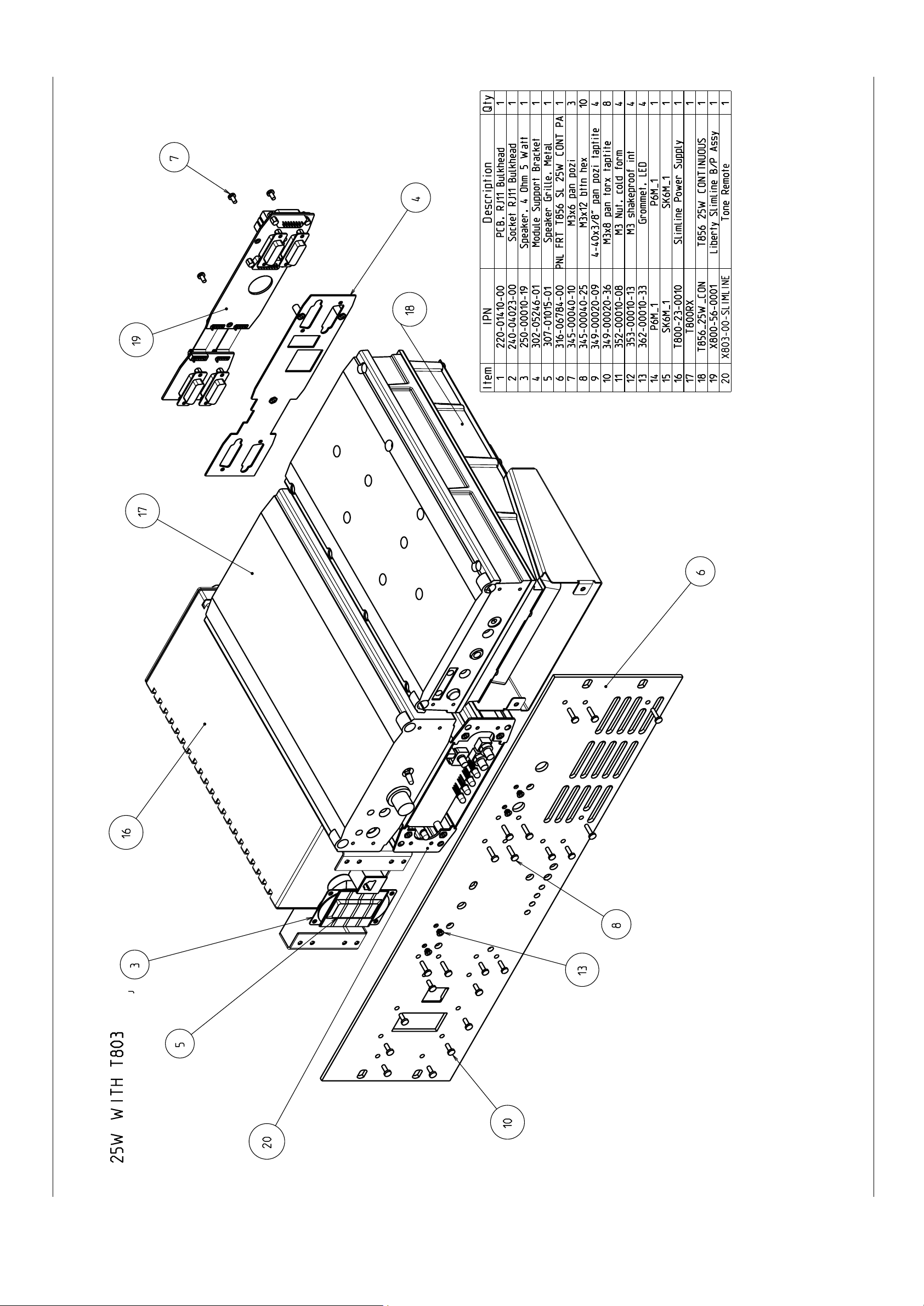
Assembly with T803 fitted
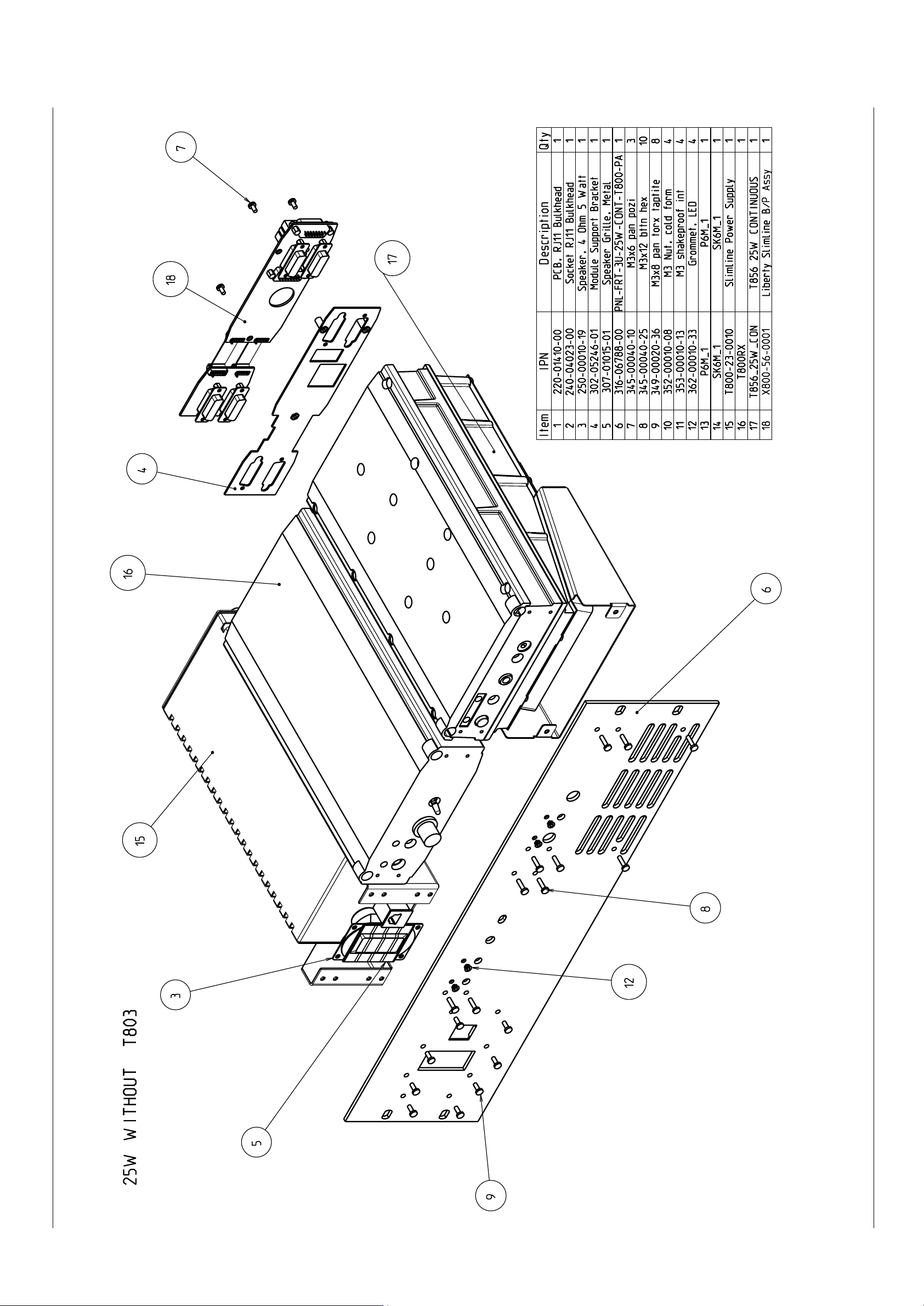
Assembly without T803 fitted
Rear View of Unit - Assembly with T803 fitted
Rear View - Cables Connected - Assembly with T803 fitted
1.1
1.1
1.1
1.2
1.2
1.1
1.2
1.3
1.4
Copyright TEL 01/03/02
Page 2

FII M800 SL2
2 M800 SL2 Installation
2.1 Mounting
The M800 SL2 unit is shipped ready assembled for fitting into racks.
All that is required is for the connection of suitable cables.
2.2 Power Supply
If a power supply other than an appropriate Tait model is used, ensure that it is capable
of providing enough current to drive the T800 system and is also free from excessive
ripple or noise.
The system should be protected by the use of appropriately rated fuses in the power
supply.
Note: It is particularly important when the prime power source is a battery that
fuses be employed in all supply lines.
2.3 Reverse Polarity & Overvoltage Protection
A crowbar diode is fitted to all T854 transmitters exciters for protection against connection to a power supply of incorrect polarity. It also provides overvoltage protection
from voltage transients caused by lightning strikes.
Note: A fuse must be fitted in the power supply line for the diode to provide effec-
tive protection.
01/03/02 Copyright TEL
Page 3
M800 SL2 FIII
2.4 Wiring
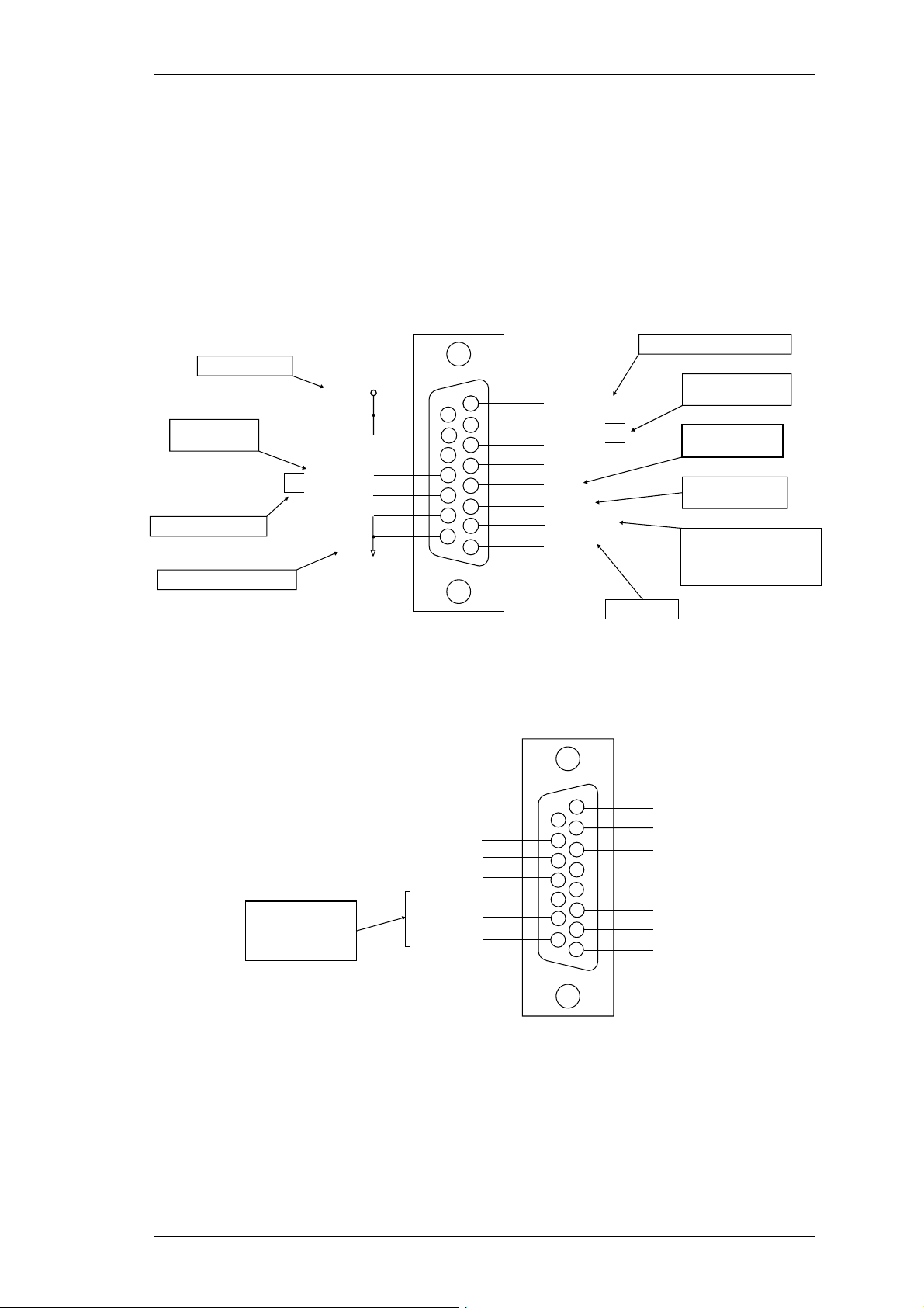
The D-range input and output connections are shown in Figure 2.1 and Figure 2.2.
Ensure that the cables are not subjected to any stresses due to tight bends or incorrect
lengths.
Make sure the RF coax cable to the N-type connector is free from sharp bends or twists.
If access to the rear of the rack frame is restricted, the cable should be long enough to
allow the chassis to be fully withdrawn from the guide.
Adjustable -50 to +10dBm
10.8 to 16V DC
Short together for
normal operation
2.0V = -110dBm
4.5V = -100dBm
0.5V/5dB
1V/15dB
External/auxiliary
audio processing
Can be configured as
Can be configured as
Audio 2 by internal link
Audio 2 by internal
resistors if required.
link resistors if required.
Refer to Part I.
Receiver gate,
open collector
Relay
Receiver gate relay
Power supply, -ve earth
+13.8V
Gate O/P
Common 1
N.O. 1
Gnd
15
10
12
13
14
11
1
9
2
3
4
5
6
7
8
Line O/P1
Line O/P2
Line O/P3
Line O/P4
RSSI
Audio 1
Serial Com
Speaker
Open drain type;
capable of sinking
2.25mA via 2k2Ω;
V max. = 5V
ds
RX DISABLE
CTCSS DISABLE
CH_SLCT 7
SERIAL COM
AUX-OUT 0
AUX-OUT 1
AUX-OUT 2
1W into 4Ω
Figure 2.1 T855 D-Range 1 Wiring - Rear View
1
9
2
10
3
11
4
12
5
13
6
14
7
15
8
CH_SLCT 0
CH_SLCT 1
CH_SLCT 2
CH_SLCT 3
CH_SLCT 4
CH_SLCT 5
CH_SLCT 6
GND
Figure 2.2 T855 D-Range 2 Wiring - Rear View
(standard T800-03-0000 kit)
Note: Figure 2.2 above shows the standard pin allocations for the T800-03-0000
auxiliary D-range kit. A T800-03 auxiliary D-range kit is also available for
special applications requiring custom internal wiring.
Copyright TEL 01/03/02
Page 4

FIV M800 SL2
01/03/02 Copyright TEL
Page 5
T856/857 Installation
220-01138-00
Assembly with T803 fitted
M800 SL2 T856/857 Installation F2.1
Copyright TEL 01/03/02
Page 6
T856/857 Installation
220-01138-00
Assembly without T803 fitted
F2.2 T856/857 Installation M800 SL2
01/03/02 Copyright TEL
 Loading...