

Page 1

TB9400 Base Station/Repeater
Installation and Operation Manual
MBC-00001-20 · Issue 20· November 2018
Page 2

Contact Information
Tait Communications
Corporate Head Office
Tait International Limited
P.O. Box 1645
Christchurch
New Zealand
For the address and telephone number of regional
offices, refer to our website: www.taitradio.com
Copyright and Trademarks
All information contained in this document is the
property of Tait International Limited. All rights
reserved. This document may not, in whole or in part,
be copied, photocopied, reproduced, translated, stored,
or reduced to any electronic medium or machinereadable form, without prior written permission from
Tait International Limited.
The word TAIT and the TAIT logo are trademarks of
Tait International Limited.
All trade names referenced are the service mark,
trademark or registered trademark of the respective
manufacturers.
Disclaimer
There are no warranties extended or granted by this
document. Tait International Limited accepts no
responsibility for damage arising from use of the
information contained in the document or of the
equipment and software it describes. It is the
responsibility of the user to ensure that use of such
information, equipment and software complies with the
laws, rules and regulations of the applicable
jurisdictions.
Enquiries and Comments
If you have any enquiries regarding this document, or
any comments, suggestions and notifications of errors,
please contact your regional Tait office.
US640974, US640977, US698339, US 702666,
US7758996, US8902804, US9107231, US9504034,
US9559967.
The AMBE+2™ voice coding Technology embodied
in this product is protected by intellectual property
rights including patent rights, copyrights and trade
secrets of Digital Voice Systems, Inc. This voice
coding Technology is licensed solely for use within this
Communications Equipment. The user of this
Technology is explicitly prohibited from attempting to
decompile, reverse engineer, or disassemble the Object
Code, or in any other way convert the Object Code into
a human-readable form.
Environmental Responsibilities
Tait International Limited is an environmentally
responsible company which supports waste
minimization, material recovery and restrictions in the
use of hazardous materials.
The European Union’s Waste Electrical and Electronic
Equipment (WEEE) Directive requires that this
product be disposed of separately from the general
waste stream when its service life is over. For more
information about how to dispose of your unwanted
Tait product, visit the Tait WEEE website at
www.taitradio.com/weee. Please be environmentally
responsible and dispose through the original supplier,
or contact Tait International Limited.
Tait International Limited also complies with the
Restriction of the Use of Certain Hazardous Substances
in Electrical and Electronic Equipment (RoHS)
Directive in the European Union.
In China, we comply with the Measures for
Administration of the Pollution Control of Electronic
Information Products. We will comply with
environmental requirements in other markets as they
are introduced.
Updates of Manual and Equipment
In the interests of improving the performance,
reliability or servicing of the equipment, Tait
International Limited reserves the right to update the
equipment or this document or both without
prior notice.
Intellectual Property Rights
This product may be protected by one or more patents
or designs of Tait International Limited together with
their international equivalents, pending patent or
design applications, and registered trade marks:
NZ409837, NZ409838, NZ415277, NZ415278,
NZ530819, NZ534475, NZ547713, NZ577009,
NZ579051, NZ579364, NZ586889, NZ610563,
NZ615954, NZ700387, NZ708662, NZ710766,
NZ711325 , NZ726313, NZ593887, AU2015215962,
AU339127, AU339391, AU2016259281,
AU2016902579, EU000915475-0001, EU 0009154750002, GB2532863, US 14/834609 Div. no 1, US15/
346518 Div.no 2, US15/350332, US15/387026 Div.,
US20150085799, US20160044572, US20160057051,
2 TB9400 Installation and Operation Manual
© Tait International Limited November 2018
Page 3

Contents
Preface . . . . . . . . . . . . . . . . . . . . . . . . . . . . . . . . . . . . . . . . . . . . . . . . . . . . . . . . . . . . . . . . . . . . . 6
Scope of Manual. . . . . . . . . . . . . . . . . . . . . . . . . . . . . . . . . . . . . . . . . . . . . . . . . . . . . . . . 6
Document Conventions . . . . . . . . . . . . . . . . . . . . . . . . . . . . . . . . . . . . . . . . . . . . . . . . . . 6
Associated Documentation. . . . . . . . . . . . . . . . . . . . . . . . . . . . . . . . . . . . . . . . . . . . . . . . 7
Publication Records . . . . . . . . . . . . . . . . . . . . . . . . . . . . . . . . . . . . . . . . . . . . . . . . . . . . . 8
1 Description . . . . . . . . . . . . . . . . . . . . . . . . . . . . . . . . . . . . . . . . . . . . . . . . . . . . . . . . . . . . . . 9
1.1 Features . . . . . . . . . . . . . . . . . . . . . . . . . . . . . . . . . . . . . . . . . . . . . . . . . . . . . . . . . 10
1.2 Modules . . . . . . . . . . . . . . . . . . . . . . . . . . . . . . . . . . . . . . . . . . . . . . . . . . . . . . . . . .11
1.3 Mechanical Assembly . . . . . . . . . . . . . . . . . . . . . . . . . . . . . . . . . . . . . . . . . . . . . . 14
1.4 Frequency Bands and Sub-bands . . . . . . . . . . . . . . . . . . . . . . . . . . . . . . . . . . . . . . 17
1.5 Applications . . . . . . . . . . . . . . . . . . . . . . . . . . . . . . . . . . . . . . . . . . . . . . . . . . . . . . 18
1.6 Licenses . . . . . . . . . . . . . . . . . . . . . . . . . . . . . . . . . . . . . . . . . . . . . . . . . . . . . . . . . 19
1.7 Theory of Operation. . . . . . . . . . . . . . . . . . . . . . . . . . . . . . . . . . . . . . . . . . . . . . . . 22
1.7.1 Signal Paths . . . . . . . . . . . . . . . . . . . . . . . . . . . . . . . . . . . . . . . . . . . . . . 24
1.7.2 Online and Offline Modes . . . . . . . . . . . . . . . . . . . . . . . . . . . . . . . . . . . 24
1.7.3 Intermodule Communications . . . . . . . . . . . . . . . . . . . . . . . . . . . . . . . . 25
1.7.4 Power Management and Distribution . . . . . . . . . . . . . . . . . . . . . . . . . . 26
1.7.5 PMU Operation on DC Input. . . . . . . . . . . . . . . . . . . . . . . . . . . . . . . . . 28
1.7.6 Front Panel Fans . . . . . . . . . . . . . . . . . . . . . . . . . . . . . . . . . . . . . . . . . . 31
2 General Safety and Regulatory Information . . . . . . . . . . . . . . . . . . . . . . . . . . . . . . . . . 32
2.1 Personal Safety. . . . . . . . . . . . . . . . . . . . . . . . . . . . . . . . . . . . . . . . . . . . . . . . . . . . 32
2.1.1 Unpacking and Moving the Equipment. . . . . . . . . . . . . . . . . . . . . . . . . 32
2.1.2 Lethal Voltages . . . . . . . . . . . . . . . . . . . . . . . . . . . . . . . . . . . . . . . . . . . 32
2.1.3 AC Power Connection . . . . . . . . . . . . . . . . . . . . . . . . . . . . . . . . . . . . . . 33
2.1.4 Explosive Environments . . . . . . . . . . . . . . . . . . . . . . . . . . . . . . . . . . . . 33
2.1.5 High Temperatures. . . . . . . . . . . . . . . . . . . . . . . . . . . . . . . . . . . . . . . . . 33
2.1.6 LED Safety (EN60825-1) . . . . . . . . . . . . . . . . . . . . . . . . . . . . . . . . . . . 33
2.1.7 Proximity to RF Transmissions / A proximité des émissions RF . . . . . 34
2.2 Equipment Safety. . . . . . . . . . . . . . . . . . . . . . . . . . . . . . . . . . . . . . . . . . . . . . . . . . 35
2.2.1 Installation and Servicing Personnel . . . . . . . . . . . . . . . . . . . . . . . . . . . 35
2.2.2 Preventing Damage to the PA . . . . . . . . . . . . . . . . . . . . . . . . . . . . . . . . 35
2.2.3 ESD Precautions . . . . . . . . . . . . . . . . . . . . . . . . . . . . . . . . . . . . . . . . . . 35
2.2.4 Anti-tampering Devices. . . . . . . . . . . . . . . . . . . . . . . . . . . . . . . . . . . . . 36
2.3 Environmental Conditions . . . . . . . . . . . . . . . . . . . . . . . . . . . . . . . . . . . . . . . . . . . 36
2.3.1 Operating Temperature Range. . . . . . . . . . . . . . . . . . . . . . . . . . . . . . . . 36
2.3.2 Humidity . . . . . . . . . . . . . . . . . . . . . . . . . . . . . . . . . . . . . . . . . . . . . . . . 36
2.3.3 Dust and Dirt . . . . . . . . . . . . . . . . . . . . . . . . . . . . . . . . . . . . . . . . . . . . . 36
2.4 Regulatory Information . . . . . . . . . . . . . . . . . . . . . . . . . . . . . . . . . . . . . . . . . . . . . 37
2.4.1 Distress Frequencies . . . . . . . . . . . . . . . . . . . . . . . . . . . . . . . . . . . . . . . 37
2.4.2 Compliance Standards . . . . . . . . . . . . . . . . . . . . . . . . . . . . . . . . . . . . . . 37
2.4.3 FCC Compliance . . . . . . . . . . . . . . . . . . . . . . . . . . . . . . . . . . . . . . . . . . 37
2.4.4 Unauthorized Modifications . . . . . . . . . . . . . . . . . . . . . . . . . . . . . . . . . 37
TB9400 Installation and Operation Manual 3
© Tait International Limited November 2018
Page 4

3 Operation . . . . . . . . . . . . . . . . . . . . . . . . . . . . . . . . . . . . . . . . . . . . . . . . . . . . . . . . . . . . . . 38
3.1 Front Panel . . . . . . . . . . . . . . . . . . . . . . . . . . . . . . . . . . . . . . . . . . . . . . . . . . . . . . . 38
3.2 Module Indicator LEDs and Switches . . . . . . . . . . . . . . . . . . . . . . . . . . . . . . . . . . 42
3.2.1 Reciter and Receiver . . . . . . . . . . . . . . . . . . . . . . . . . . . . . . . . . . . . . . . 42
3.2.2 PA. . . . . . . . . . . . . . . . . . . . . . . . . . . . . . . . . . . . . . . . . . . . . . . . . . . . . . 44
3.2.3 PMU. . . . . . . . . . . . . . . . . . . . . . . . . . . . . . . . . . . . . . . . . . . . . . . . . . . . 45
4 Installation . . . . . . . . . . . . . . . . . . . . . . . . . . . . . . . . . . . . . . . . . . . . . . . . . . . . . . . . . . . . . 47
4.1 Before You Begin . . . . . . . . . . . . . . . . . . . . . . . . . . . . . . . . . . . . . . . . . . . . . . . . . . 48
4.1.1 Equipment Security . . . . . . . . . . . . . . . . . . . . . . . . . . . . . . . . . . . . . . . . 48
4.1.2 Grounding and Lightning Protection . . . . . . . . . . . . . . . . . . . . . . . . . . . 48
4.1.3 Equipment Ventilation . . . . . . . . . . . . . . . . . . . . . . . . . . . . . . . . . . . . . . 48
4.1.4 Ambient Temperature Sensor. . . . . . . . . . . . . . . . . . . . . . . . . . . . . . . . . 48
4.1.5 Cabinet and Rack Ventilation. . . . . . . . . . . . . . . . . . . . . . . . . . . . . . . . . 49
4.2 Unpacking and Moving the Subrack . . . . . . . . . . . . . . . . . . . . . . . . . . . . . . . . . . . 51
4.3 Identifying the Equipment . . . . . . . . . . . . . . . . . . . . . . . . . . . . . . . . . . . . . . . . . . . 53
4.4 Initial Setting Up . . . . . . . . . . . . . . . . . . . . . . . . . . . . . . . . . . . . . . . . . . . . . . . . . . 55
4.4.1 Confirming Operation . . . . . . . . . . . . . . . . . . . . . . . . . . . . . . . . . . . . . . 55
4.4.2 Working with Configurations. . . . . . . . . . . . . . . . . . . . . . . . . . . . . . . . . 57
4.4.3 Customizing the Configuration . . . . . . . . . . . . . . . . . . . . . . . . . . . . . . . 58
4.4.4 Recommended Configuration Settings . . . . . . . . . . . . . . . . . . . . . . . . . 58
4.4.5 Restricted Port Numbers . . . . . . . . . . . . . . . . . . . . . . . . . . . . . . . . . . . . 58
4.4.6 Changing the Root Password . . . . . . . . . . . . . . . . . . . . . . . . . . . . . . . . . 59
4.4.7 Tuning the Reciter and Receiver . . . . . . . . . . . . . . . . . . . . . . . . . . . . . . 60
4.5 Installing the Base Station on Site . . . . . . . . . . . . . . . . . . . . . . . . . . . . . . . . . . . . . 65
4.5.1 General Installation Advice . . . . . . . . . . . . . . . . . . . . . . . . . . . . . . . . . . 65
4.5.2 Equipment Required . . . . . . . . . . . . . . . . . . . . . . . . . . . . . . . . . . . . . . . 66
4.5.3 Mounting the Subrack . . . . . . . . . . . . . . . . . . . . . . . . . . . . . . . . . . . . . . 67
4.6 Connecting Up the Base Station. . . . . . . . . . . . . . . . . . . . . . . . . . . . . . . . . . . . . . . 70
4.6.1 Connection Overview . . . . . . . . . . . . . . . . . . . . . . . . . . . . . . . . . . . . . . 71
4.6.2 Connecting AC Power . . . . . . . . . . . . . . . . . . . . . . . . . . . . . . . . . . . . . . 73
4.6.3 Connecting DC Power . . . . . . . . . . . . . . . . . . . . . . . . . . . . . . . . . . . . . . 74
4.6.4 Connecting the Auxiliary DC Power Output. . . . . . . . . . . . . . . . . . . . . 75
4.6.5 Connecting RF . . . . . . . . . . . . . . . . . . . . . . . . . . . . . . . . . . . . . . . . . . . . 76
4.6.6 Connecting an External Frequency Reference. . . . . . . . . . . . . . . . . . . . 77
4.6.7 Connecting a 1PPS Source . . . . . . . . . . . . . . . . . . . . . . . . . . . . . . . . . . 78
4.6.8 Ethernet Connection. . . . . . . . . . . . . . . . . . . . . . . . . . . . . . . . . . . . . . . . 79
4.6.9 Connecting General Purpose Inputs and Outputs . . . . . . . . . . . . . . . . . 80
5 Working with Base Stations from Your PC . . . . . . . . . . . . . . . . . . . . . . . . . . . . . . . . . . . 81
5.1 PC Recommendations . . . . . . . . . . . . . . . . . . . . . . . . . . . . . . . . . . . . . . . . . . . . . . 82
5.2 Connecting Your PC to the Base Station . . . . . . . . . . . . . . . . . . . . . . . . . . . . . . . . 82
5.2.1 Logging In . . . . . . . . . . . . . . . . . . . . . . . . . . . . . . . . . . . . . . . . . . . . . . . 83
5.2.2 Setting the IP Address . . . . . . . . . . . . . . . . . . . . . . . . . . . . . . . . . . . . . . 84
5.2.3 Security Certificates. . . . . . . . . . . . . . . . . . . . . . . . . . . . . . . . . . . . . . . . 85
5.2.4 Local Connection to a Base Station. . . . . . . . . . . . . . . . . . . . . . . . . . . . 85
5.2.5 Troubleshooting Connection Problems . . . . . . . . . . . . . . . . . . . . . . . . . 86
5.2.6 Finding a Lost or Forgotten IP Address. . . . . . . . . . . . . . . . . . . . . . . . . 86
5.2.7 Setting Up Authentication . . . . . . . . . . . . . . . . . . . . . . . . . . . . . . . . . . . 87
5.3 Working with the Web Interface. . . . . . . . . . . . . . . . . . . . . . . . . . . . . . . . . . . . . . . 88
4 TB9400 Installation and Operation Manual
© Tait International Limited November 2018
Page 5

5.3.1 Monitoring Operation . . . . . . . . . . . . . . . . . . . . . . . . . . . . . . . . . . . . . . 89
5.3.2 Troubleshooting Alarms . . . . . . . . . . . . . . . . . . . . . . . . . . . . . . . . . . . . 90
5.3.3 Viewing Configuration Settings . . . . . . . . . . . . . . . . . . . . . . . . . . . . . . 91
5.3.4 Viewing the Base Station and Network Identity . . . . . . . . . . . . . . . . . . 94
5.4 Basic Tasks. . . . . . . . . . . . . . . . . . . . . . . . . . . . . . . . . . . . . . . . . . . . . . . . . . . . . . . 95
5.4.1 User Settings . . . . . . . . . . . . . . . . . . . . . . . . . . . . . . . . . . . . . . . . . . . . . 95
5.4.2 Taking the Base Station Offline. . . . . . . . . . . . . . . . . . . . . . . . . . . . . . . 95
5.4.3 Troubleshooting Alarms . . . . . . . . . . . . . . . . . . . . . . . . . . . . . . . . . . . . 95
5.4.4 Disabling the Front Panel Keypad. . . . . . . . . . . . . . . . . . . . . . . . . . . . . 96
5.4.5 Preparing to Download Firmware . . . . . . . . . . . . . . . . . . . . . . . . . . . . . 96
5.4.6 Working with Configuration Files . . . . . . . . . . . . . . . . . . . . . . . . . . . . . 98
5.4.7 Setting Up Custom Alarms . . . . . . . . . . . . . . . . . . . . . . . . . . . . . . . . . . 98
5.4.8 Subaudible Signaling. . . . . . . . . . . . . . . . . . . . . . . . . . . . . . . . . . . . . . . 99
5.4.9 Checking for Interference on a Receive Channel . . . . . . . . . . . . . . . . . 99
5.4.10 Configuring Single Base Stations . . . . . . . . . . . . . . . . . . . . . . . . . . . . 100
5.4.11 Configuring Receive-Only Base Stations . . . . . . . . . . . . . . . . . . . . . . 100
5.4.12 Configuring Base Stations in a Channel Group. . . . . . . . . . . . . . . . . . 100
6 Maintenance. . . . . . . . . . . . . . . . . . . . . . . . . . . . . . . . . . . . . . . . . . . . . . . . . . . . . . . . . . . 102
7 Troubleshooting . . . . . . . . . . . . . . . . . . . . . . . . . . . . . . . . . . . . . . . . . . . . . . . . . . . . . . . . 104
8 Replacing Modules . . . . . . . . . . . . . . . . . . . . . . . . . . . . . . . . . . . . . . . . . . . . . . . . . . . . . 105
8.1 Saving the Base Station’s Configuration . . . . . . . . . . . . . . . . . . . . . . . . . . . . . . . 105
8.2 Preliminary Disassembly . . . . . . . . . . . . . . . . . . . . . . . . . . . . . . . . . . . . . . . . . . . 106
8.3 Replacing a Reciter . . . . . . . . . . . . . . . . . . . . . . . . . . . . . . . . . . . . . . . . . . . . . . . 108
8.4 Replacing a Power Amplifier. . . . . . . . . . . . . . . . . . . . . . . . . . . . . . . . . . . . . . . . .110
8.5 Replacing a Power Management Unit . . . . . . . . . . . . . . . . . . . . . . . . . . . . . . . . . .112
8.6 Replacing the Module Guide Rails . . . . . . . . . . . . . . . . . . . . . . . . . . . . . . . . . . . .113
8.7 Replacing the Subrack Interconnect Board . . . . . . . . . . . . . . . . . . . . . . . . . . . . . .114
8.8 Final Reassembly . . . . . . . . . . . . . . . . . . . . . . . . . . . . . . . . . . . . . . . . . . . . . . . . . .115
Appendix A – Interface Pin Allocations . . . . . . . . . . . . . . . . . . . . . . . . . . . . . . . . . . . . . . . . .116
System Interface Connector . . . . . . . . . . . . . . . . . . . . . . . . . . . . . . . . . . . . . . . . . . . . . .116
Ethernet Connector. . . . . . . . . . . . . . . . . . . . . . . . . . . . . . . . . . . . . . . . . . . . . . . . . . . . .116
PMU Auxiliary DC Output . . . . . . . . . . . . . . . . . . . . . . . . . . . . . . . . . . . . . . . . . . . . . .116
Appendix B – Inter-Module Connections . . . . . . . . . . . . . . . . . . . . . . . . . . . . . . . . . . . . . . . .117
Dual 50W Base Station . . . . . . . . . . . . . . . . . . . . . . . . . . . . . . . . . . . . . . . . . . . . . . . . .117
Single 50W Base Station . . . . . . . . . . . . . . . . . . . . . . . . . . . . . . . . . . . . . . . . . . . . . . . .118
100W Base Station. . . . . . . . . . . . . . . . . . . . . . . . . . . . . . . . . . . . . . . . . . . . . . . . . . . . .119
Receive-only Base Station . . . . . . . . . . . . . . . . . . . . . . . . . . . . . . . . . . . . . . . . . . . . . . 120
Appendix C – Identifying Front Panels . . . . . . . . . . . . . . . . . . . . . . . . . . . . . . . . . . . . . . . . 121
Glossary . . . . . . . . . . . . . . . . . . . . . . . . . . . . . . . . . . . . . . . . . . . . . . . . . . . . . . . . . . . . . . . . . . 122
Tait Software License Agreement . . . . . . . . . . . . . . . . . . . . . . . . . . . . . . . . . . . . . . . . . . . . . 128
Simplified EU Declaration of Conformity . . . . . . . . . . . . . . . . . . . . . . . . . . . . . . . . . . . . . . 132
TB9400 Installation and Operation Manual 5
© Tait International Limited November 2018
Page 6
Preface
Scope of Manual
This manual provides information on installing and operating the TB9400
base station. It is intended for use by experienced technicians familiar with
installing and operating base station equipment. It also includes
configuration, maintenance and troubleshooting information.
Except where stated otherwise, the information in this manual generally
applies to both standard and receive-only base stations and reciters.
When “reciter” is referred to, this generally applies also to the receiver
(receive-only reciter). References to power amplifiers (PAs) and transmitting obviously do not apply to receive-only equipment.
Unless mentioned specifically, this manual will use the term “base station”
to refer to both base station and repeater.
Document Conventions
The TB9400 base station has a web interface with an accordion menu on
the left side of the screen. “Configure > Base Station > Channels” means
click Configure in the top-level menu, then in the expanded Configure
menu click Base Station, and finally click on the Channels tab on that page.
Within this manual, four types of alerts may be given to the reader. The
following paragraphs illustrate each type of alert and its associated symbol.
Warning This alert is used when there is a hazardous situation
which, if not avoided, could result in death or serious injury.
Caution This alert is used when there is a hazardous situation which,
if not avoided, could result in minor or moderate injury.
Notice This alert is used to highlight information that is required to
ensure procedures are performed correctly. Incorrectly performed procedures could result in equipment damage or malfunction.
This icon is used to draw your attention to information that may
improve your understanding of the equipment or procedure.
6 Preface TB9400 Installation and Operation Manual
© Tait International Limited November 2018
Page 7

Associated Documentation
The following associated documentation for this product is available on the
Tait support website.
■ TB9400 Specifications Manual (MBC-00002-xx)
■ TN9400 P25 Trunked Network Maintenance Manual (MNC-00001-xx)
■ TaitNet P25 Trunked Networks with TB9400 Base Stations System
Manual (MBA-00064-xx)
■ TaitNet Analog Conventional Networks with TB9400 Base Stations
System Manual (MND-00001-xx)
■ Safety and Compliance Information (MBA-00012-xx)
The characters xx represent the issue number of the documentation.
Technical notes are published from time to time to describe applications for
Tait products, to provide technical details not included in manuals, and to
offer solutions for any problems that arise. Technical notes are available in
PDF format from the Tait support website. For more information contact
your regional Tait office.
TB9400 Installation and Operation Manual Preface 7
© Tait International Limited November 2018
Page 8

Publication Records
Issue Publication Date Description
20 November 2018 General updates for the 2.55 release
Advice for configuring subaudible signaling.
19 July 2018 General updates for the 2.50 release
Addition of B2 band.
Clarified that HH band is nominally 378 - 420. All frequencies can be used
except for the range at 406 - 406.1 (exclusive).
Updated type designators.
Smaller updates throughout.
18 March 2018 General updates for the 2.45 release
Publication Record now shows most recent manual issue at top of table
Added note about fill-in receiver to “8.4 Replacing a Power Amplifier”
Clarified “Bands and Sub-Bands” table
Updated section 5.2.4 “Connecting a Networked PC to a Base Station”
Added site controller table to the “1.6. Licenses” section
HH band is now released as 50W and receive only
17 November 2017 General updates for the 2.40 release.
Added definition of “integral voter” to Glossary on page 122
Added solution to Internet Explorer black screen in Connecting Your PC to
the Base Station on page 82.
Added notice regarding fan operation to Front Panel Fans on page 31.
Added information on cancelling a firmware package to Subaudible
Signaling on page 99.
Updated information on downloading firmware packages Setting Up a
Central Package Server on page 97.
Added notice regarding the base station resetting to Setting the IP Address
on page 84.
Added new HH band information throughout.
16 July 2017 General updates for version 2.35 release.
General minor wording and content changes throughout
Added P25 Conventional Simulcast Repeater to Features on page 10
Central voter and satellite licences listed as alternatives Licenses on
page 19.
Updated description for the ‘Digital Fixed Station’ Interface in Licenses on
page 19.
Updated the “Licenses and applicability” table for Central Voter, IP
Networking Satellite, and Simulcast.
Added new H3 band information throughout.
Screenshots have been updated in various places.
8 Preface TB9400 Installation and Operation Manual
© Tait International Limited November 2018
Page 9
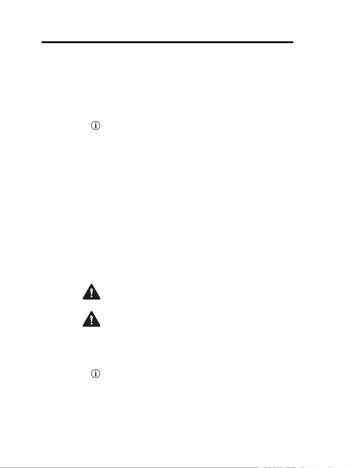
1 Description
The Tait TB9400 base station is a robust state-of-the-art digital fixed
station that combines Tait’s proven strengths in reliability, high
performance and modular design with software-based configurability and
operation, digital signal processing, and voice-over-IP technology.
The TB9400 operates as a transceiver in Project 25 trunked, trunked
simulcast, and P25 conventional networks. It is capable of either P25 Phase
1 FDMA operation, or 6.25kHz equivalent P25 Phase 2 TDMA operation.
The TB9400 can also operate in an analog conventional simulcast or
non-simulcast multi-site network.
The TB9400 combines industry-leading digital voice quality with rugged
design specifications and intuitive user interfaces. These products are
designed to meet the needs of the public safety and public service sectors.
The ability of the base station to link stations using standard Internet
Protocol communications, and to add features through software options
ensures that P25 systems designed with the TB9400 are scalable in both
size and functionality.
Its Ethernet interface provides built-in network connectivity, allowing the
TB9400 to join with other TB9400 base stations to form a channel group.
This network supports voice-over-IP and remote management of all base
stations via a web browser.
TB9400 Installation and Operation Manual Description 9
© Tait International Limited November 2018
Page 10

1.1 Features
The following are some of the features of the base station:
■ Fully compliant with the P25 Common Air Interface. Can therefore
■ Supports P25 Phase 1 operation with either C4FM or LSM modulation
■ Supports P25 Phase 2 operation.
■ Analog conventional repeater operation.
■ Analog conventional simulcast operation on an IP backbone requiring
■ Integrated built-in voting facility. No external voter is needed.
■ Can be completely managed remotely from a PC running a web
■ An integrated wiring solution is provided for the system control bus and
■ Reciters (receiver/exciter modules) can be replaced without affecting
■ Rugged construction with generous heatsinks and fan-forced cooling
interoperate with any similarly compliant radios.
on the transmitter
no audio calibration or training.
browser: configuration, alarm monitoring, fault diagnosis, feature and
firmware upgrades. Alarms can also be reported via SNMP traps,
allowing integration with an SNMP-based network management
system.
DC power connections to each module in the subrack.
the operation of other reciters in the same subrack.
for continuous operation from –22°F to +140°F (–30°C to +60°C).
10 Description TB9400 Installation and Operation Manual
© Tait International Limited November 2018
Page 11
1.2 Modules
The base station consists of a subrack with up to two transmit/receive
channels, or up to four receive-only channels.
The single PMU (power management unit) supplies and manages power to
the whole subrack (refer to “Theory of Operation” on page 22). One reciter
and one PA (power amplifier) are needed for each transmit/receive channel.
The PA is not required for a receive-only base station. There is also a front
panel with user controls and fans. The modules are interconnected at the
front of the subrack. External connections to the modules are located at the
rear.
Modules come in different variants depending, for example, on the RF
band or the supply voltage.
Each module is inserted into the 4U subrack from the front and is secured
at the front with a metal clamp. Both clamp and module are easily removed
for rapid module replacement. The modules are secured laterally with
plastic guides that clip into the top and bottom of the subrack. These guides
can be easily repositioned to change the configuration of a subrack. The
heavier modules are also secured laterally by metal tabs at the rear of the
subrack.
The following provides a brief description of the available modules.
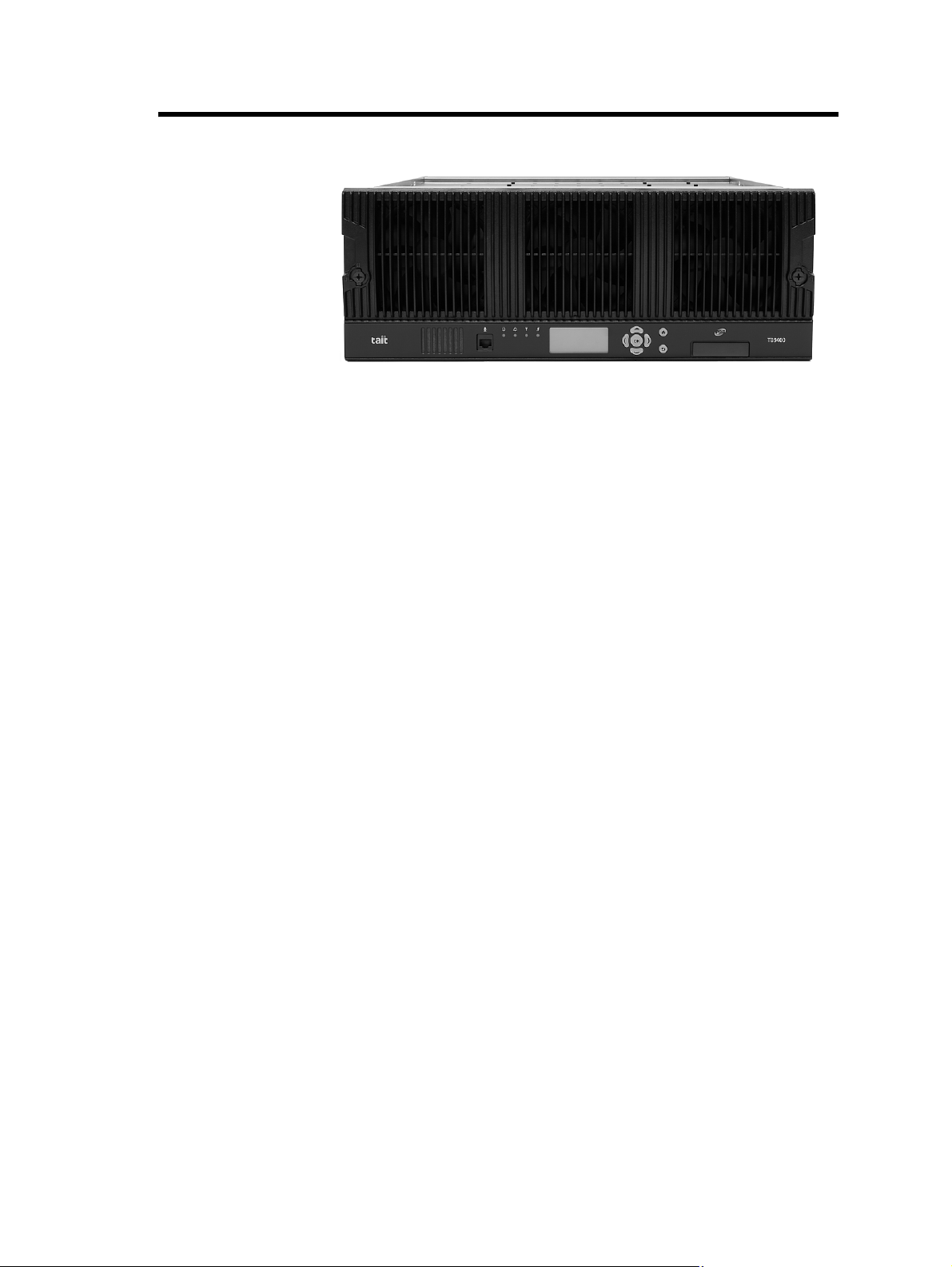
Subrack The 4U subrack is made of passivated steel and is designed to fit into a
standard 19 inch rack or cabinet. The subrack is fitted with an interconnect
board that connects the system control bus and power to the modules and
front panel. The position of a module in the subrack is defined by the socket
on the subrack interconnect board to which the module is connected by the
system control bus.
TB9400 Installation and Operation Manual Description 11
© Tait International Limited November 2018
Page 12
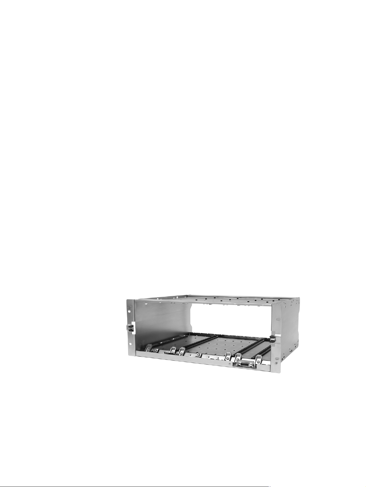
Front Panel
The front panel is mounted onto the subrack with two quick-release
fasteners. It incorporates the indicator LEDs, four-line LCD display, user
controls, ambient temperature sensor and cooling fans.
The indicator LEDS allow some monitoring of the operational status of the
base station. The user controls and display allow the technician to
configure the IP address of each module. Refer to “Front Panel” on page 38
for more information.
The base stations have different front panel ducting arrangements
depending on PA type and power. Front panels may not be interchangeable.
The microphone input and speaker are not used in this release of the
TB9400.
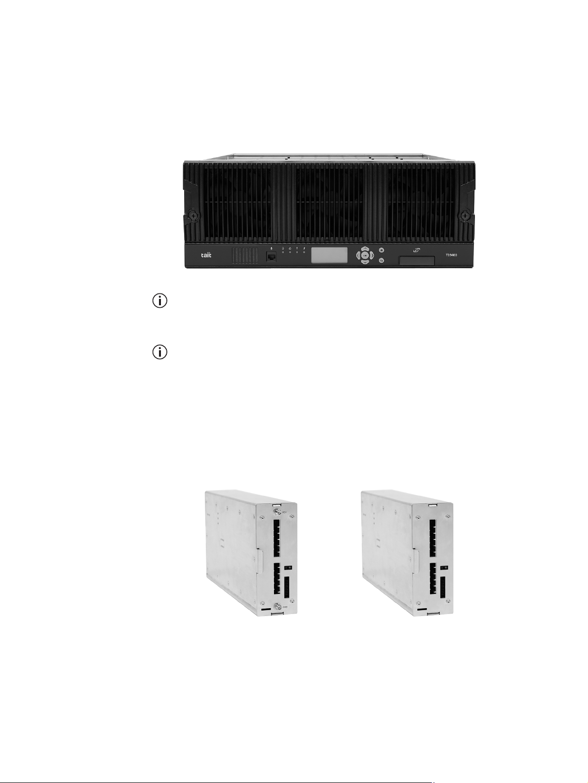
Reciter The reciter module comprises the receiver, exciter and digital control
circuitry. The reciter provides the Ethernet interface and system inputs and
outputs.
Receiver modules (receive-only reciters) are not fitted with the transmit
circuitry or front panel SMA connectors, and are physically unable to
transmit.
reciter receiver
12 Description TB9400 Installation and Operation Manual
© Tait International Limited November 2018
Page 13
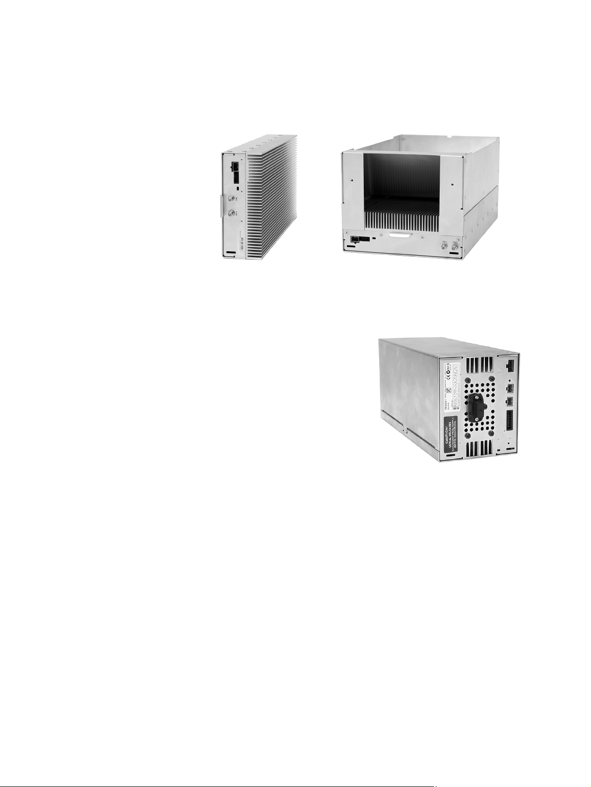
Power Amplifier
The PA amplifies the RF output from the reciter and is available in 50W
and 100W models.
The 50W model mounts vertically in the subrack, while the 100W model
mounts horizontally as it has a wider heatsink. The 100W PA is also fitted
with an airflow duct.
50W PA 100W PA
Both models are designed to operate on the 28VDC output provided by the
PMU. PAs are not required in a receive-only base station.
Power Management
Unit
The PMU provides the 28VDC
power supply for the modules in the
subrack. It can operate on
120/230VAC 50/60Hz nominal, and
12, 24 or 48VDC nominal. The input
voltage can be AC, DC, or both AC
and DC, depending on the model. The
PMU also has an auxiliary DC output
of 13.65VDC, 27.3VDC, or
54.6VDC, depending on the model.
AC and DC PMU shown
TB9400 Installation and Operation Manual Description 13
© Tait International Limited November 2018
Page 14
1.3 Mechanical Assembly
This section illustrates the main mechanical components of the base
station.
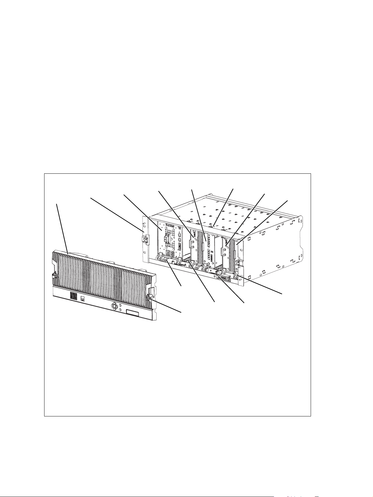
Figure 1.1 below shows the configuration for a typical dual 50W base
station. The subrack has six slots, numbered from right to left as viewed
from the front of the subrack. The PMU occupies slots 5 and 6, with the
reciter and PA pairs to the right of it in slots 1 to 4. Each PA is mounted
vertically with its heatsink facing its associated reciter. The PMU and each
reciter/PA pair have their own cooling fans.
The front panel can be easily removed from the subrack by undoing two
quick-release fasteners. Refer to “Replacing Modules” on page 105 for
more details.
Figure 1.1 Mechanical assembly - dual 50W base station with front panel
b
c
.
g
d
e
f
1@
1!
1#
front panel
b
subrack
c
PMU
d
PA 2
e
reciter 2
f
cable retaining clip
g
PA 1
h
reciter 1
i
module retaining clamp
j
subrack interconnect board
1)
plastic guide rail
1!
subrack interconnect board retaining clamp
1@
front panel fastener
1#
h
i
j
1)
14 Description TB9400 Installation and Operation Manual
© Tait International Limited November 2018
Page 15
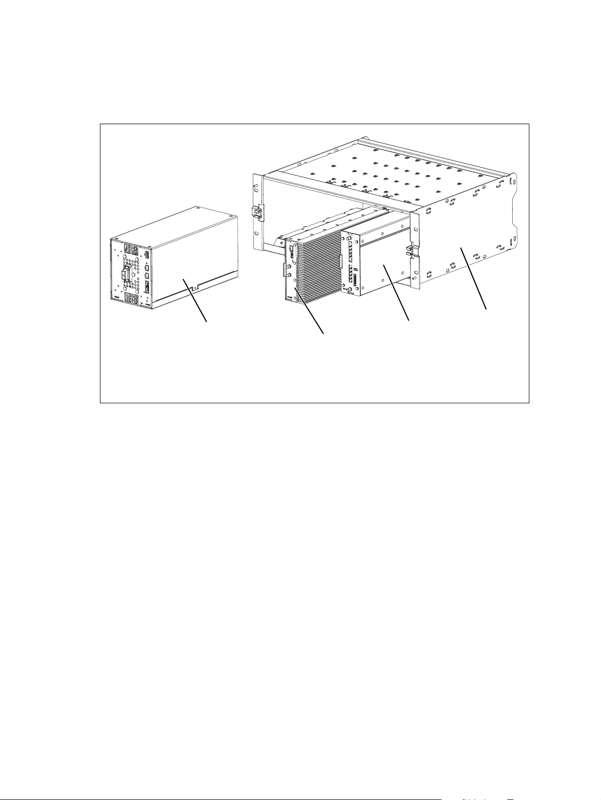
Figure 1.2 below shows the configuration for a typical single 50W base
station. The PMU again occupies slots 5 and 6, with the reciter in slot 1 and
PA in slot 2. The PA is mounted vertically with its heatsink facing the
reciter. The PMU and the reciter/PA pair have their own cooling fans.
Figure 1.2 Mechanical assembly - single 50W base station
b
c
PMU
50W PA
b
c
d
e
e
d
reciter
subrack
TB9400 Installation and Operation Manual Description 15
© Tait International Limited November 2018
Page 16
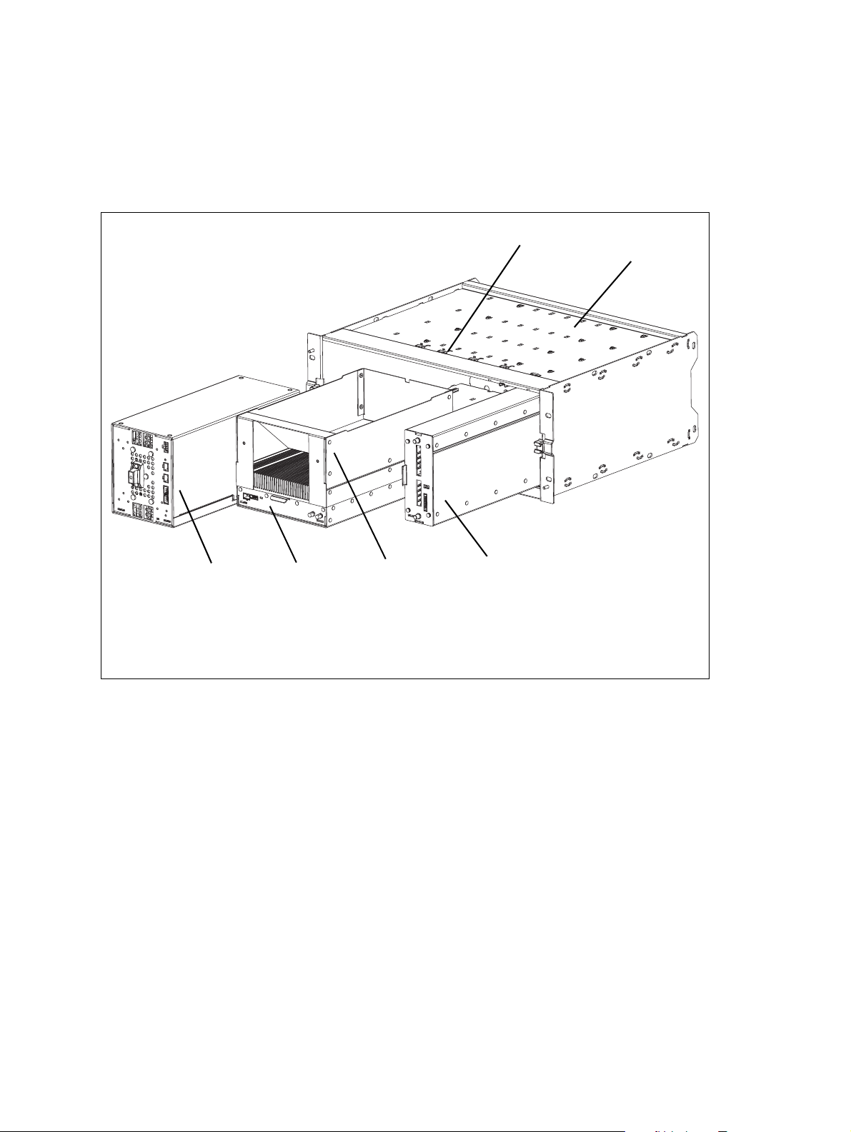
Figure 1.3 below shows the configuration for a typical 100 W base station.
The PMU occupies slots 5 and 6, with the PA directly beside it in slots 3
and 4. The reciter occupies slot 1. Unlike the 50W PAs, the 100W PA is
mounted horizontally with the heatsink facing upwards. It is also fitted with
an airflow duct to channel the airflow from the cooling fan through the
heatsink fins.
Figure 1.3 Mechanical assembly - single 100W base station
g
f
PMU
b
PA
c
airflow duct
d
b
c
d
e
reciter
e
subrack
f
cable retaining clip
g
16 Description TB9400 Installation and Operation Manual
© Tait International Limited November 2018
Page 17

1.4 Frequency Bands and Sub-bands
Much of the circuitry in the base station is common to all frequency bands,
and is therefore covered by a single description in this manual. In some
cases the descriptions refer to specific bands or sub-bands, and these are
identified with the letters listed in the following table.
Frequency
Identification Frequency Band and Sub-band 50W 100W Receive-only
B band B2 = 136MHz to 156MHz
B3 = 148MHz to 174MHz
H band HH = 378MHz to 420MHz
H1 = 400MHz to 440 MHz
H2 = 440MHz to 480 MHz
H3 = 470MHz to 520 MHz
K band K4 = 762 MHz to 870MHz
a. The actual frequency coverage in this band is:
Transmit: 762MHz to 776 MHz, and 850 MHz to 870 MHz
Receive: 794MHz to 824MHz
In Brazil, for K band, the TB9400 is considered to be configured as a base
station with retransmission of received signals.
✓
✓
✓
✓
✓
✓
a
✓✓ ✓
✓
✓
✓
✓
✓
✓
✓
✓
✓
✓
✓
✓
TB9400 Installation and Operation Manual Description 17
© Tait International Limited November 2018
Page 18

1.5 Applications
The TB9400 operates in P25 trunked networks (Phase 1 or Phase 2), P25
conventional networks and analog conventional networks. It operates as a
stand-alone repeater/base station, or as part of a channel group, providing
receiver voting and simulcast transmission. All air interfaces and system
types support simulcast operation.
In P25 Phase 2 operation, a single TB9400 base station can provide two
traffic channels, since each radio frequency (physical channel) provides
two logical channels (timeslots). However, it can provide only one control
channel, since control channels are still P25 Phase 1.
In a trunked simulcast network, the transmitters in the channel group are
synchronized and transmit simultaneously on the same frequency. Each
transmitter needs a highly accurate 1PPS pulse and an external frequency
reference, so that it can time transmissions with the required accuracy. Also
required is an NTP source that is derived from the same source as the 1PPS
signal. This will ensure a common timestamp in logs across all units in the
system. An external frequency reference, along with an NTP source and
1PPS signal derived from the same GPS source, are also essential for all
reciters for P25 Phase 2 operation.
In a P25 conventional network, the TB9400 operates as a single or wide
area conventional repeater, with receiver voting and optional simulcast.
Dispatch connection is via two distinct interfaces:
■ P25 standard DFSI connection (up to three connections simultaneously)
■ Tait P25 Console Gateway, supporting conversion between P25 and
analog consoles with MDC1200 signalling
In an analog conventional network it can operate as a repeater with
CTCSS
The base station can also operate as part of an analog conventional
simulcast network and is fully IP-connected. The base station also features
an internally integrated voter, and therefore requires no external voter.
The base station can be provided as a receive-only variant in systems that
need sites to enhance the receive coverage. The receiver module in a
receive-only base station is physically unable to transmit.
For more information on these applications, refer to the Help and
appropriate Tait System Manual.
1
or DCS subaudible signaling.
1. Private Line (PL).
18 Description TB9400 Installation and Operation Manual
© Tait International Limited November 2018
Page 19

1.6 Licenses
Some operational functions of the base station are controlled by licenses.
These functions will not work unless you purchase the appropriate feature
license and enable the feature set controlled by that license. The feature sets
currently available are listed below.
Base stations can operate in distinct network tiers according to the feature
licences on the base station.
The compatibility rules are defined in the following table:
P25 Access Trunking Operation Compatible Not operate Not operate
P25 Express6 Trunking Operation Compatible Compatible Not operate
Site controller
Access Express6 Full system
P25 Trunking Operation Compatible Compatible Compatible
Base station
Analog Air Interface
(TBAS041 - Default
Licence)
P25 Common Air
Interface
(TBAS050)
P25 Trunking
Operation
(TBAS056)
Digital Fixed Station
Interface (TBAS060)
Central Voter
(TBAS061)
The central voter and satellite licences listed below are alternatives.
This is the licence that accompanies the base station. A base station with
this license can operate as a repeater in an analog conventional network.
Allows a base station to transmit and receive P25 Phase 1 C4FM digital
voice transmissions.
Allows a base station to become a trunking master, functioning as an
interface between the trunking site controller and the channel group.
Allows a base station (master or satellite) to have a TCCP connection
(control or status) to a trunking site controller.
Allows the base station to integrate with dispatch consoles supporting
DFSI (Digital Fixed Station Interface).
P25 and analog. This feature allows a base station to act as a central voter.
Simulcast
(TBAS062)
TB9400 Installation and Operation Manual Description 19
© Tait International Limited November 2018
This feature is required in base stations that have transmitters and belong
to a P25 Phase 1 simulcast or analog simulcast network
in the central voter of a simulcast channel.
1. Not needed for receive-only base stations.
2
1
. It is also required
Page 20

P25 Trunking
Failsoft
(TBAS063)
Linear Simulcast
Modulation
(TBAS065)
P25 Phase 2
Trunking
(TBAS066)
P25 Phase 2
Simulcast
(TBAS069)
Allows trunked channels that become isolated from a site controller to
perform simple conventional operation and to interface to a digital dispatch
system. If a trunked channel consists of several base stations in a channel
group, only the central voter (normally the master) needs this license. It is
then able to become the failsoft repeater for that channel group.
P25 only. Allows the base station to transmit using the LSM modulation
1
scheme
. This scheme allows increased site separation in simulcast
networks. Also requires the Simulcast license (TBAS062).
This feature allows the base station to operate in trunking mode using
two-slot TDMA as defined by the P25 Phase 2 standards.
This feature is required in base stations that have transmitters and belong
1
to a P25 Phase 2 simulcast network
of a P25 Phase 2 simulcast channel
. It is also required in the central voter
2
. Also requires the P25 Phase 2
Trunking (TBAS066) and Simulcast (TBAS062) licenses. Tait also
recommends adding the Linear Simulcast Modulation (TBAS065) license
as it provides improved RF performance.
P25 Access
Trunking Operation
(TBAS070)
IP Networking
Satellite
(TBAS071)
P25 Express6
Trunking Operation
(TBAS072)
Enables single site P25 trunking.
All system types and all air interface types. This feature allows a base
station to be part of a channel group without requiring the Central Voter
(TBAS061) license.
Enables P25 trunking with up to 6 sites.
2. The central voter in a simulcast channel needs the respective Phase 1 or
Phase 2 simulcast license. Normally, a transceiver member of a simulcast
channel will have a simulcast license, so this constraint should not be an
issue.
20 Description TB9400 Installation and Operation Manual
© Tait International Limited November 2018
Page 21

Table 1.1 Licenses and applicability
Licence Name Air Interface System Type
TBAS041 Analog Air Interface Analog Conventional
TBAS060 Digital Fixed Station Interface Analog & P25 Phase 1 Conventional
TBAS061 Central Voter Analog & P25 Phase 1 & 2 Trunked, Conventional
TBAS071 IP Networking Satellite Analog & P25 Phase 1 & 2 Trunked, Conventional
TBAS062 Simulcast Analog & P25 Phase 1 & 2 Trunked, Conventional
TBAS050 P25 Common Air Interface P25 Phase 1 & 2 Trunked, Conventional
TBAS065 Linear Simulcast Modulation P25 Phase 1 & 2 Trunked, Conventional
TBAS056 P25 Trunking Operation P25 Phase 1 & 2 Trunked
TBAS063 P25 Trunking Failsoft P25 Phase 1 & 2 Trunked
TBAS066 P25 Phase 2 Trunking P25 Phase 1 & 2 Trunked
TBAS070 P25 Access Trunking Operation P25 Phase 1 & 2 Trunked
TBAS072 P25 Express6 Trunking Operation P25 Phase 1 & 2 Trunked
TBAS069 P25 Phase 2 Simulcast P25 Phase 2 Trunked
TB9400 Installation and Operation Manual Description 21
© Tait International Limited November 2018
Page 22
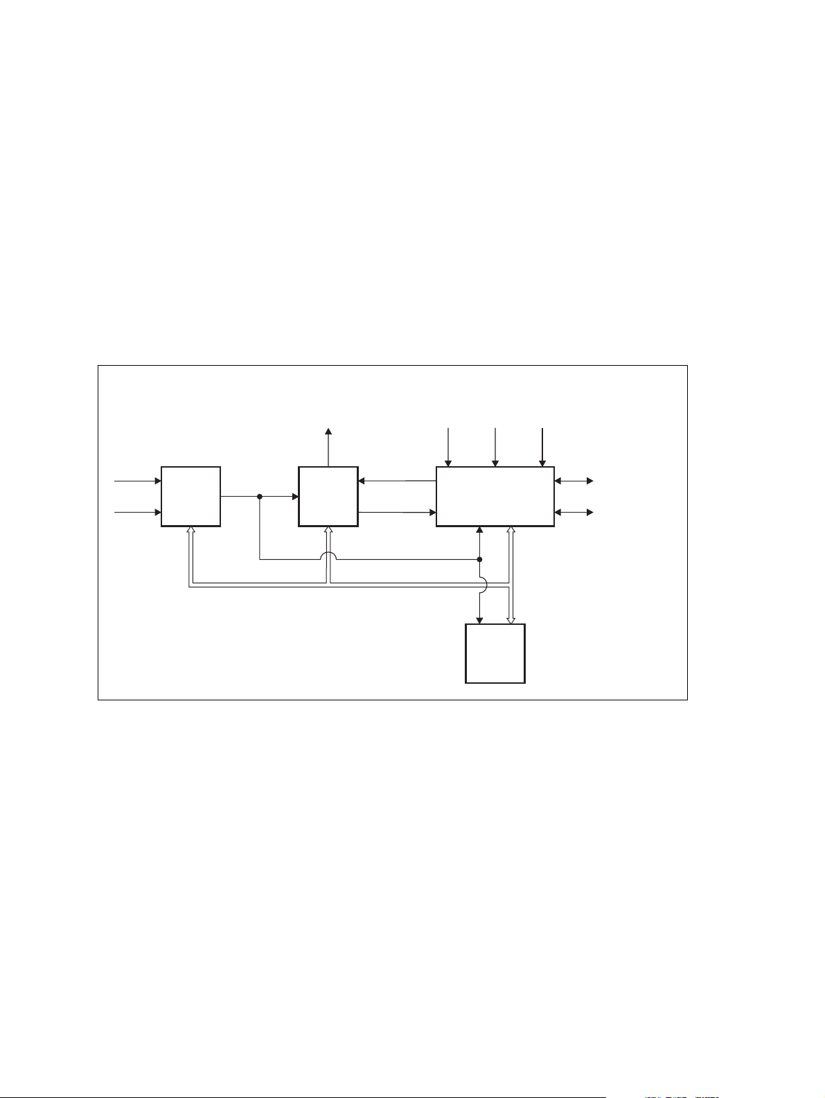
1.7 Theory of Operation
The reciter receives RF signals from its RF input and sends RF from its RF
output to the PA, along with a PA key signal. The PA sends an RF feedback
signal to the reciter for linearization and power control purposes. The
reciter also receives signals from, and sends signals to, the system
interface, the Ethernet interface, and the front panel (see Figure 1.4).
A system control bus interconnects the modules and carries alarm and
control signaling between the reciter and the other modules (refer to
“Intermodule Communications” on page 25 for more details).
The Ethernet interface carries voice over IP and also allows maintainer
access via a web browser.
Figure 1.4 Base station high-level diagram
RF To
Antenna
AC Input
DC Input
A receive-only base station has a receiver instead of a reciter,
and does not have a PA.
PMU
28VDC
PA
System Control Bus
RF+PAKey
RF Feedback
RF From
Antenna
1PPS
Reciter
Front
Panel
External
Reference
Frequency
System Input
and Output
Ethernet Interface
to Network
22 Description TB9400 Installation and Operation Manual
© Tait International Limited November 2018
Page 23
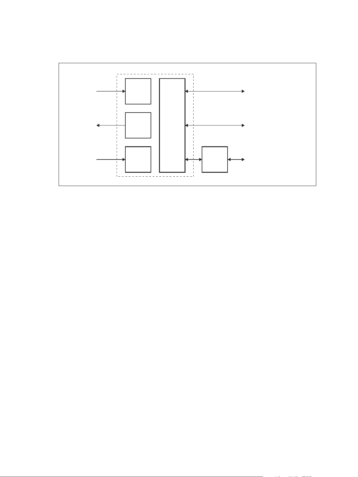
The reciter carries out signal processing and has overall control of the base
station. Its circuit boards are shown in Figure 1.5.
Figure 1.5 Reciter boards
RF Input
RF Output
RF Input
(feedback
from PA)
Receiver
Board
Transmit
Forward
Board
Transmit
Reverse
Board
Reciter
Control
Board
Front
Panel
System Input
and Output
Ethernet Interface
to Network
Maintainer Access
The receiver board contains all the receiver circuitry, while the exciter
circuitry is located on the transmit forward board.
The reciter control board converts information between analog and digital
and controls the maintainer’s access via the front panel. It performs the air
interface signal processing for digital P25 operation, gives the base station
an identity as a network element, and provides the physical connections for
the Ethernet and system interfaces.
TB9400 Installation and Operation Manual Description 23
© Tait International Limited November 2018
Page 24
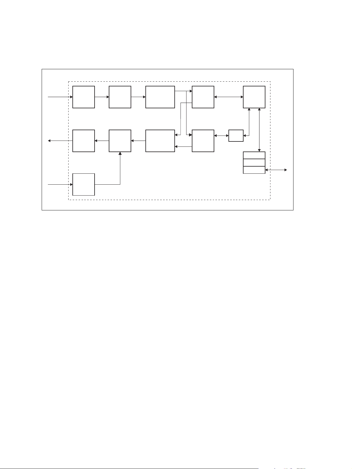
1.7.1 Signal Paths
Figure 1.6 gives an overview of signal paths within the reciter.
Figure 1.6 Reciter signal paths
Receive
RF Interface
Demodulator
P25
Modem
ControlADC DDC
Transmit
RF Interface
Transmit
RF Interface
(feedback
from PA)
DAC
ADC
Cartesian
Loop
Modulator
FM
Baseband
Audio
G.711
Protocol
Stack
Reciter Control Board
RTP
UDP
IP
Ethernet
Interface
Digital P25 signals from the receive RF interface pass through the digital
receiver and P25 modem to the control software in the control processor.
The control software passes the signal through the Ethernet interface to the
site controller (P25 trunked networks), to the console gateway
(conventional networks), or for a satellite, to the central voter in a simulcast
system.
Input to the Ethernet interface can be from the site controller (P25 trunked
networks), from the console gateway (conventional networks), or from the
central voter in a simulcast system. These inputs are processed by the
control processor and passed through the P25 modem to the transmitter. If
the base station is itself a central voter, this input can also be a received
signal, which is voted on and sent back through the Ethernet interface to the
site controller.
1.7.2 Online and Offline Modes
The base station normally operates in Online mode, but you can put it into
Offline mode via its web interface.
Online Mode In Online mode, the base station is in service and performs its normal
functions of transmitting and receiving radio signals.
24 Description TB9400 Installation and Operation Manual
© Tait International Limited November 2018
Page 25
Offline Mode
Offline mode allows a maintenance engineer to carry out tasks that can not
be done while the base station is in service - such as activating firmware or
running diagnostic tests.
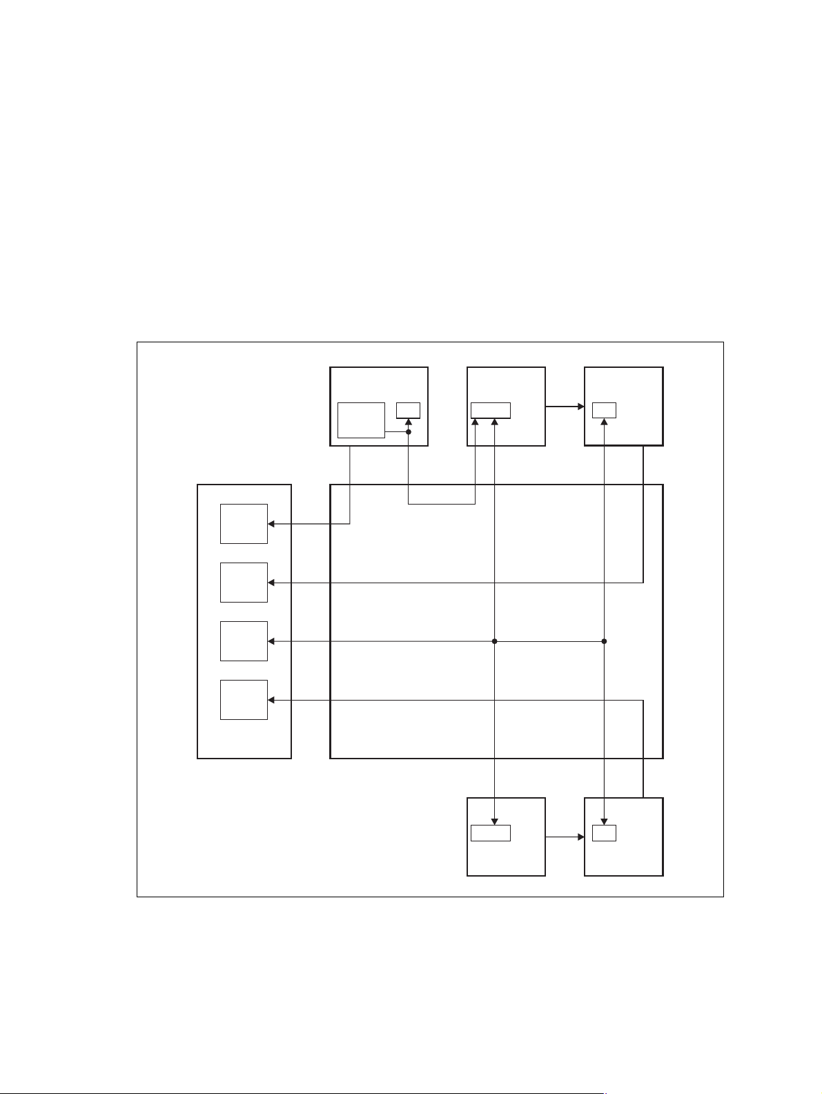
1.7.3 Intermodule Communications
A system control bus and a subrack interconnect board link the modules in
the subrack and carry alarm and control signaling between the reciter and
the other modules, as shown in Figure 1.7.
Specific configuration settings for dual base stations are described in
“Recommended Configuration Settings” on page 58.
Figure 1.7 Intermodule communication paths
PMU
2
I C Current
Source
mP
2
2
IC
Reciter 1
mP
RS-485
PA 1
mP
RS-485IC
Fan
FanFan
Fan 3:
PMU
Fan 1:
Reciter 1/
PA 1
User
Controls
Fan 2:
Reciter 2/
PA 2
Front Panel
Subrack Interconnect Board
mP
Reciter 2
RS-485RS-485 Fan
mP
PA 2
TB9400 Installation and Operation Manual Description 25
© Tait International Limited November 2018
Page 26

1.7.4 Power Management and Distribution
The PMU manages the supply of power to ensure uninterrupted operation
of the base station. A range of parameters is monitored and these can
trigger alarms that are sent to the reciter. Alarms can be monitored via the
web interface and reported via SNMP traps; they are also recorded in the
reciter’s internal log file.
AC to DC
Changeover
When the PMU has an AC and a DC module, the base station can be
powered by either the AC (mains) or the DC (battery) supply. The base
station will default to the AC supply if both supplies are provided. If the
AC supply becomes unavailable, a seamless changeover from the AC to
DC supply takes place, providing that the battery voltage is above the
configured minimum startup voltage. You can use a web browser to check
whether the base station is running on battery or mains power.
DC Operation When the base station is running off the DC supply and the battery voltage
falls below the configured minimum, the base station will enter battery
protection mode to protect the battery and base station equipment. The
standby power supply card maintains the power to the PMU
microprocessor, while the rest of the PMU is shut down. When the battery
voltage rises to the configured startup setting, power is resumed to the DC
supply. Refer to “PMU Operation on DC Input” on page 28 for more
detailed information.
Auxiliary Power
Control
Distribution Figure 1.8 shows how power is distributed to modules in the subrack. The
The output from the auxiliary power supply board can be used to power
other site equipment. The maximum output is 40W.
28VDC output from the PMU is fed directly to the PA in a single base
station, or directly to PA 1 in a dual base station, and to the other modules
via the subrack interconnect board. Power to the reciters and front panel is
current-limited by self-resetting fuses on the subrack board.
The AC converter has a series switch which breaks the phase input to the
converter. The DC input, however, has much higher current ratings. Its
switch does not disconnect power from the DC converter itself, but disables
the converter by switching off its control circuitry.
The outputs from both the AC and DC high power converters are added
together and fed to the modules via the high-current outputs. The auxiliary
output is also tapped off this summed output.
26 Description TB9400 Installation and Operation Manual
© Tait International Limited November 2018
Page 27
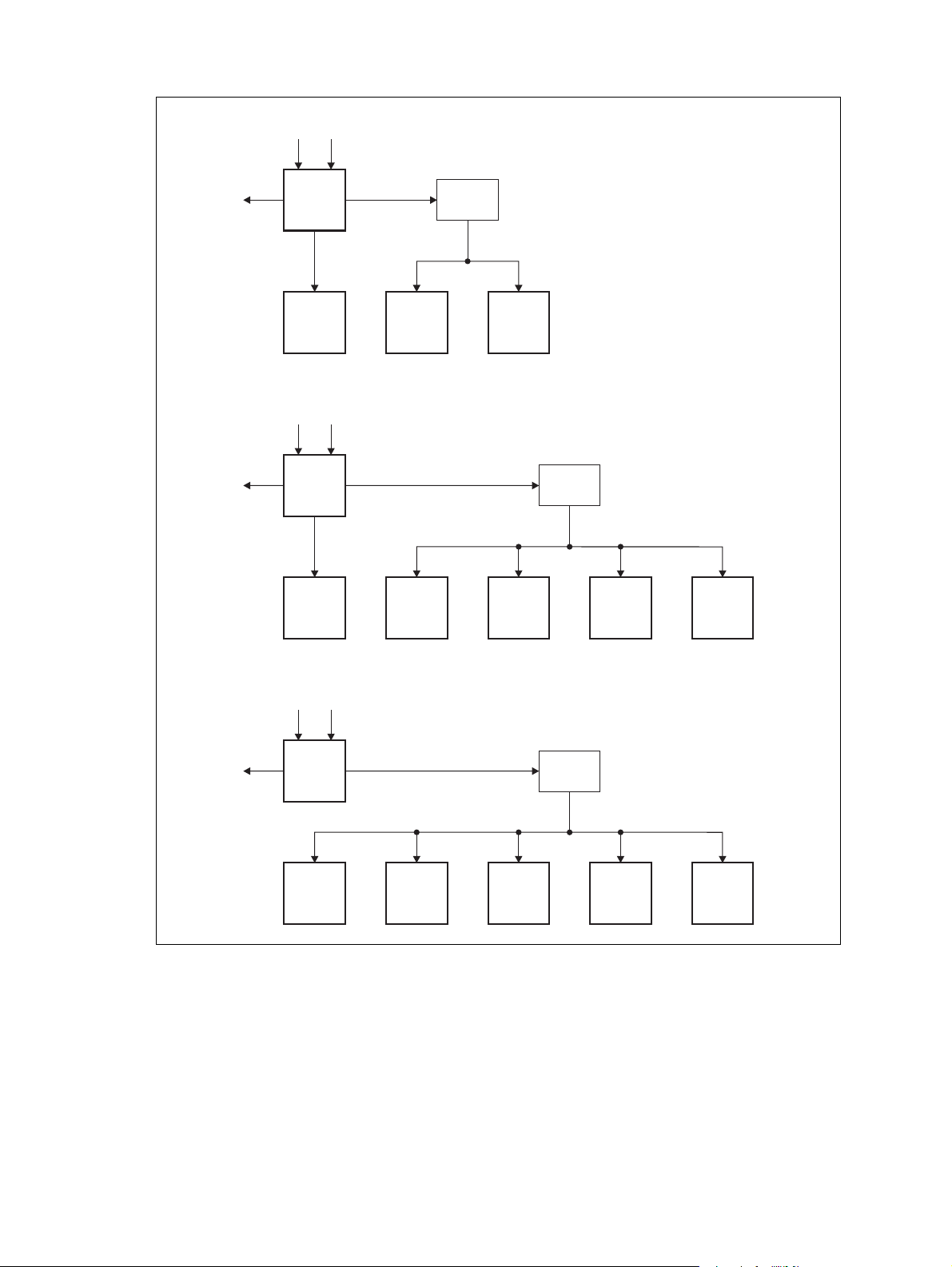
Figure 1.8 Subrack power distribution
Single
Dual
DC AC
Aux. DC 28V
Aux. DC 28V
PMU
28V
PA Reciter
DC AC
PMU
28V
Subrack
Board
Front
Panel
Subrack
Board
Receive-only
PA 1 PA 2 Reciter 1
DC AC
Aux. DC 28V
PMU
Receiver 1
Receiver 3
Subrack
Board
Reciter 2
Receiver 4Receiver 2
Front
Panel
Front
Panel
TB9400 Installation and Operation Manual Description 27
© Tait International Limited November 2018
Page 28

1.7.5 PMU Operation on DC Input
The operation of the PMU on DC input is controlled by three sets of
parameters:
■ user-programmable alarms
■ user-programmable startup and shutdown limits
■ battery protection limits
The voltage range for each of these parameters is provided in Table 1.2 on
page 29. Figure 1.9 on page 30 illustrates how these parameters interact,
and how they control the operation of the PMU over a range of DC input
voltages.
Alarms User-programmable alarms can be set for low or high battery voltage
(Configure > Alarms > Thresholds). The alarms will be triggered when the
set voltage levels are reached. These limits are subject to the tolerances of
the battery protection circuitry, as stated in “Battery Protection (Fail-safe)
Limits” in Table 1.2.
Startup and
Shutdown Limits
Battery Protection
Limits
The user-programmable startup and shutdown limits allow for adjustable
startup and shutdown voltages (Configure > Base Station >
Miscellaneous). These limits can be adjusted for different numbers of
battery cells, or for the particular requirements of the base station
operation. Once the limits are reached, the PMU will shut down. These
limits are subject to the tolerances of the battery protection circuitry, as
stated in “Battery Protection (Fail-safe) Limits” in Table 1.2.
Notice It is possible to set the startup voltage of the base station
below the nominal voltage of the battery. Continuing to use a battery for
extended periods when it is below its nominal voltage will severely
shorten its service life. For more information on battery management,
we recommend that you consult the battery manufacturer.
The battery protection limits are set in hardware at the factory, and cannot
be adjusted by the user. These limits will not be reached under normal
operation conditions, but are provided as “fail-safe” measures to protect the
battery from deep discharge. They also remove the need for low-voltage
disconnect modules.
28 Description TB9400 Installation and Operation Manual
© Tait International Limited November 2018
Page 29

Table 1.2 PMU DC voltage limits
Parameter
User-programmable Alarms
Low Battery Voltage
High Battery Voltage
User-programmable Limits
Startup Voltage (after shutdown)
Shutdown Voltage
Battery Protection (Fail-safe) Limits
Startup Voltage
Undervoltage Shutdown
Overvoltage Shutdown
Overvoltage Shutdown Reset
a. The information in this table is extracted from the Specifications Manual. Refer to the latest issue of this manual
for the most up-to-date and complete PMU specifications.
b. Using the base station’s web interface.
b
b
a
Voltage Range
12V PMU 24V PMU 48 V PMU
10V to 14V
14V to 17.5V
10.9V to 15V ± 0.3 V
10V to 13.5V ± 0.3 V
10.8V +0.2 V
9.5V +0.3 V
18.1V +
17.1V +
0.3V
0.3V
20V to 28V
28V to 35V
21.8V to 30V ±0.5V
20V to 27V ±0.5V
21.6V +
19V +0.5V
36.2V +
34.2V +
0.5V
0.5V
0.5V
40V to 56V
56V to 70V
43.6V to 60V ±1V
40V to 54V ±1V
43.2V +
38V +1V
72.4V +
68.4V +
1V
1V
1V
TB9400 Installation and Operation Manual Description 29
© Tait International Limited November 2018
Page 30
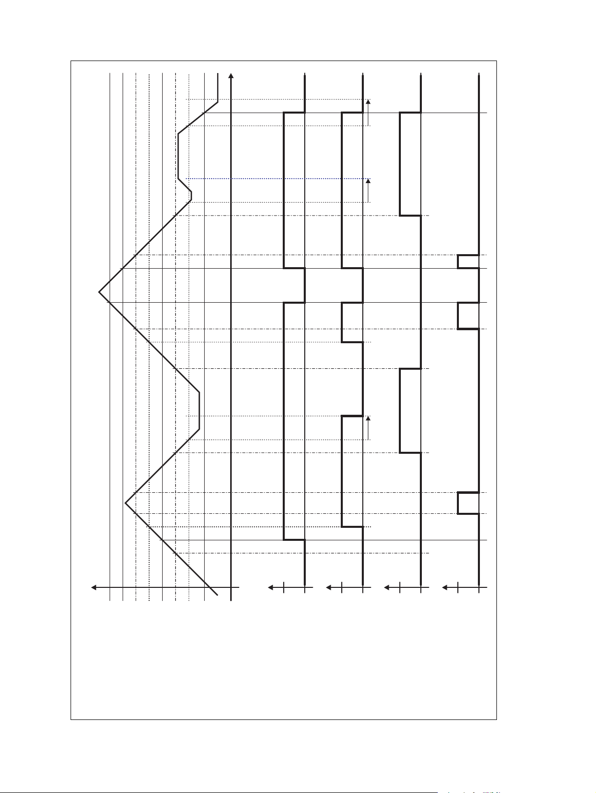
Figure 1.9 PMU alarm thresholds and voltage limits when operating on DC
Time
DC Input Voltage
Overvoltage Shutdown (HW)
Overvoltage Shutdown Reset (HW)
High Battery Voltage Alarm (SW Alarm)
Startup Voltage (SW)
Startup Voltage (HW)
Shutdown Voltage (SW)
Undervoltage Shutdown (HW)
Low Battery Voltage Alarm (SW Alarm)
30s delay 30s delay 30s delay
Run
0V
Hardware Behaviour
Stop
Run
Software Control &
Hardware Combined
Stop
Software Alarm
Off
Active
Software Alarm
(Low Battery Voltage)
Off
Active
(High Battery Voltage)
30 Description TB9400 Installation and Operation Manual
© Tait International Limited November 2018
Page 31

1.7.6 Front Panel Fans
The front panel is equipped with three fans. One fan is for the PMU, and
the other two are for the reciter/PA pairs in a 50W base station, or for the
PA and reciter in a 100W base station, or for the receivers in a receive-only
base station (refer to “Appendix C – Identifying Front Panels” on
page 121). Front panel fans do not operate continuously, but are switched
on and off as needed. The PMU and PA control their own fan. Reciters
request the front panel to turn on their fan. The reciter in slot 1can also
carry out a fan test on all three fans.
Front panel fans are 3-wire fans (power, ground, and rotation detect). The
reciter can monitor whether the fans are rotating and generate an alarm if
any of the fans fail.
The fans turn on for the duration of time the base station takes to boot
from power up. The fans also turn on for a few seconds after the front
panel is refitted to a base station that is powered up.
Configuring Fan
Control
The operation of the PA fan is configurable via the web interface; you can
specify the threshold temperature at which the fan will be turned on, and
set the fan to operate only when the PA is transmitting.
Notice If a fan is not operational, the fan alarm will only be raised
when the fan is turned on, not at system start-up. To avoid discovering
a fan fault after leaving the site, Tait recommends running a diagnostics
fan test.
The PMU fan has fixed on/off thresholds and a defined set of duty cycles
based on the PMU temperature and load current, as described in the
following table.
PMU Temperature Current Fan Duty Cycle
<149°F (65°C) < 4 A
4A–6A
6A–8A
8A–12A
12A–14A
≥15A
>149°F (65°C) –– always on
always off
2 minutes on, 8 minutes off
2 minutes on, 5 minutes off
3 minutes on, 3 minutes off
4 minutes on, 1 minute off
always on
TB9400 Installation and Operation Manual Description 31
© Tait International Limited November 2018
Page 32
2 General Safety and Regulatory
Information
This chapter provides general information on safety precautions for
operating the base station.
2.1 Personal Safety
2.1.1 Unpacking and Moving the Equipment
To prevent personal injury and equipment damage, we recommend that two
people unpack and move the equipment.
Caution A subrack complete with modules can weigh up to 55lb
(25kg), or up to 62lb (28kg) complete with packaging. We recommend
that you have another person help you unpack and move the equipment.
The TBAA03-16 carrying handles will make it easier to move the
equipment once it has been unpacked. If necessary, remove the modules
from the subrack before moving it (refer to “Replacing Modules” on
page 105). In all cases follow safe lifting practices.
2.1.2 Lethal Voltages
Warning The PMU contains voltages that may be lethal. Refer
to the ratings label on the rear of the module.
The equipment must be installed so that the rear of the PMU is located in a
service access area which is accessible only by qualified personnel. The
PMU must be connected to the mains supply source by qualified personnel
in accordance with local and national regulations.
Disconnect the mains IEC connector and wait for five minutes for the
internal voltages to self-discharge before dismantling. The AC power
on/off switch does not isolate the PMU from the mains. It breaks only
the phase circuit, not the neutral.
The PMU should be serviced only by qualified technicians. There are no
user-replaceable parts inside. If the PMU is damaged and does not function
properly, stop the module safely and contact your regional Tait office
immediately.
All servicing should be carried out only when the PMU is powered through
a mains isolating transformer of sufficient rating.
32 General Safety and Regulatory Information TB9400 Installation and Operation Manual
© Tait International Limited November 2018
Page 33

2.1.3 AC Power Connection
English (en) The PMU must be connected to a grounded mains
Norsk (no) Apparatet må tilkoples jordet stikkontakt.
Suomi (fi) Laite on liitettävä suojamaadoitus-koskettimilla
Svenska (sv) Apparaten skall anslutas till jordat uttag.
2.1.4 Explosive Environments
socket-outlet.
varustettuun pistorasiaan.
Warning
caps or in an explosive atmosphere. Operating the equipment in
these environments is a definite safety hazard.
Do not operate the equipment near electrical blasting
2.1.5 High Temperatures
Take care when handling a PMU or PA which has been operating recently.
Under extreme operating conditions (+140°F [+60°C] ambient air
temperature) or high duty cycles, the external surfaces of the PMU and PA
can reach temperatures of up to +176°F (+80°C).
2.1.6 LED Safety (EN 60825-1)
This equipment contains Class 1 LED Products.
TB9400 Installation and Operation Manual General Safety and Regulatory Information 33
© Tait International Limited November 2018
Page 34

2.1.7 Proximity to RF Transmissions / A proximité des émissions RF
To comply with the RF Field Limits for Devices Used by the General
a
Public for (Uncontrolled Environment)
, a safe separation distance of at
least 12 feet (3.6 metres) from the antenna system should be maintained.
This figure is calculated for a typical installation, employing one 100W
base station transmitter. Other configurations, including installations at
multi-transmitter sites, must be installed so that they comply with the
relevant RF exposure standards.
a. Reference Standards
Health Canada’s Safety Code 6: Limits of Human Exposure to
Radiofrequency Electromagnetic Energy in the Frequency Range from
3kHz to 300GHz
USA Federal Communications Commission OET bulletin 65
(47CFR 1.1310)
IEEE C95.1 2005: Standard for Safety Levels with Respect to Human
Exposure to Radio Frequency Electromagnetic Fields, 3kHz to
300GHz
Pour respecter les limites imposées au champ RF au niveau des
équipements utilisés par le grand public (environnement non contrôlé)
a
une distance de séparation de sécurité d’au moins 3.6 mètres du bloc
d’antenne devrait être observée.
,
Ce nombre est calculé pour une installation typique, ayant un émetteur de
station de base de 100W. D’autres configurations, incluant les installations
ayant des sites de plusieurs émetteurs, doivent être installées de façon à se
conformer aux normes pertinentes des expositions RF.
a. Normes de référence
Code de sécurité 6 de Santé Canada: Limites d'exposition humaine à
l’énergie électromagnétique radioélectrique dans la gamme de
fréquences de 3kHz à 300GHz
Commission fédérale des communications (FCC) des Etats Unis
d’Amérique bulletin OET numéro 65 (47CFR 1.1310)
IEEE C95.1 2005: Norme pour les niveaux de sécurité compatibles avec
l'exposition des personnes aux champs électromagnétiques de
radiofréquence 3kHz à 300GHz
34 General Safety and Regulatory Information TB9400 Installation and Operation Manual
© Tait International Limited November 2018
Page 35

2.2 Equipment Safety
2.2.1 Installation and Servicing Personnel
The equipment should be installed and serviced only by qualified
personnel.
2.2.2 Preventing Damage to the PA
The base station has been designed to operate safely under a wide range of
antenna loading conditions. Transmitting into a low VSWR will maximize
the power delivered to the antenna.
Notice Do not remove the load from the PA while it is transmitting.
Load transients (switching or removing the load) can damage the PA output
stage. See “Connecting RF” on page 76 for recommendations.
2.2.3 ESD Precautions
Notice This equipment contains devices which are susceptible to
damage from static charges. You must handle these devices carefully
and according to the procedures described in the manufacturers’ data
books.
We recommend you purchase an antistatic bench kit from a reputable
manufacturer and install and test it according to the manufacturer’s
instructions. Figure 2.1 shows a typical antistatic bench set-up.
You can obtain further information on antistatic precautions and the
dangers of electrostatic discharge (ESD) from standards such as ANSI/
ESD S20.20-1999 or BS EN 100015-4 1994.
Figure 2.1 Typical antistatic bench set-up
common point ground
(building ground or
mains ground)
dissipative rubber
bench mat
conductive wrist strap
TB9400 Installation and Operation Manual General Safety and Regulatory Information 35
© Tait International Limited November 2018
Page 36

2.2.4 Anti-tampering Devices
All network elements should be physically secured, where possible. This
includes the use of locked cabinets and the use of seals on connectors.
All network connectors should be sealed with the stick-on type of seal. The
purpose of the seals is to detect unauthorized tampering. The seal should
reveal if any of the connectors have been unplugged or if any unauthorized
equipment has been plugged in.
The seals must be difficult to remove without breaking, and must bridge
between the cable and equipment side (plug and socket) of the connection.
Seals must cover any unused network sockets. This includes the Ethernet
connector on the rear panel, any spare switch ports, and the console port on
the router and switch.
The seals must be difficult to reproduce. A sticker initialed or signed by the
technician should satisfy this.
Seals must be replaced if they need to be disturbed during maintenance.
2.3 Environmental Conditions
2.3.1 Operating Temperature Range
The operating temperature range of the equipment is –22°F to +140°F
(–30°C to +60°C) ambient temperature. Ambient temperature is defined as
the temperature of the air at the intake to the cooling fans.
2.3.2 Humidity
The humidity should not exceed 95% relative humidity through the
specified operating temperature range.
2.3.3 Dust and Dirt
For uncontrolled environments, the level of airborne particulates must not
exceed 100µg/m
3
.
36 General Safety and Regulatory Information TB9400 Installation and Operation Manual
© Tait International Limited November 2018
Page 37

2.4 Regulatory Information
2.4.1 Distress Frequencies
The 406 to 406.1MHz frequency range is reserved worldwide for use by
Distress Beacons. Do not program transmitters to operate in this frequency
range.
2.4.2 Compliance Standards
This equipment has been tested and approved to various national and
international standards. Refer to the latest issue of the Specifications
Manual for a complete list of these standards.
2.4.3 FCC Compliance
This equipment complies with:
■ CFR Title 47 Part 15 Class B (except PMU):
Radiated and conducted emissions, and electromagnetic susceptibility specifications of the Federal Communications Commission
(FCC) rules for the United States.
Operation is subject to the following two conditions:
a. This device may not cause harmful interference, and
b. This device must accept any interference received, including
interference that may cause undesired operation.
■ CFR Title 47 Part 15 Class A (PMU only):
Radiated and conducted emissions, and electromagnetic susceptibility specifications of the Federal Communications Commission
(FCC) rules for the United States.
Operation is subject to the following two conditions:
a. This device may not cause harmful interference, and
b. This device must accept any interference received, including
interference that may cause undesired operation.
2.4.4 Unauthorized Modifications
Any modifications you make to this equipment which are not authorized by
Tait may invalidate your compliance authority’s approval to operate the
equipment.
The manufacturer is not responsible for any radio or TV interference
caused by unauthorized modifications to this equipment. Such
modifications could void the user’s authority to operate the equipment.
TB9400 Installation and Operation Manual General Safety and Regulatory Information 37
© Tait International Limited November 2018
Page 38
3 Operation
This section describes the user controls and indicator LEDs on the front
panel and on the base station modules.
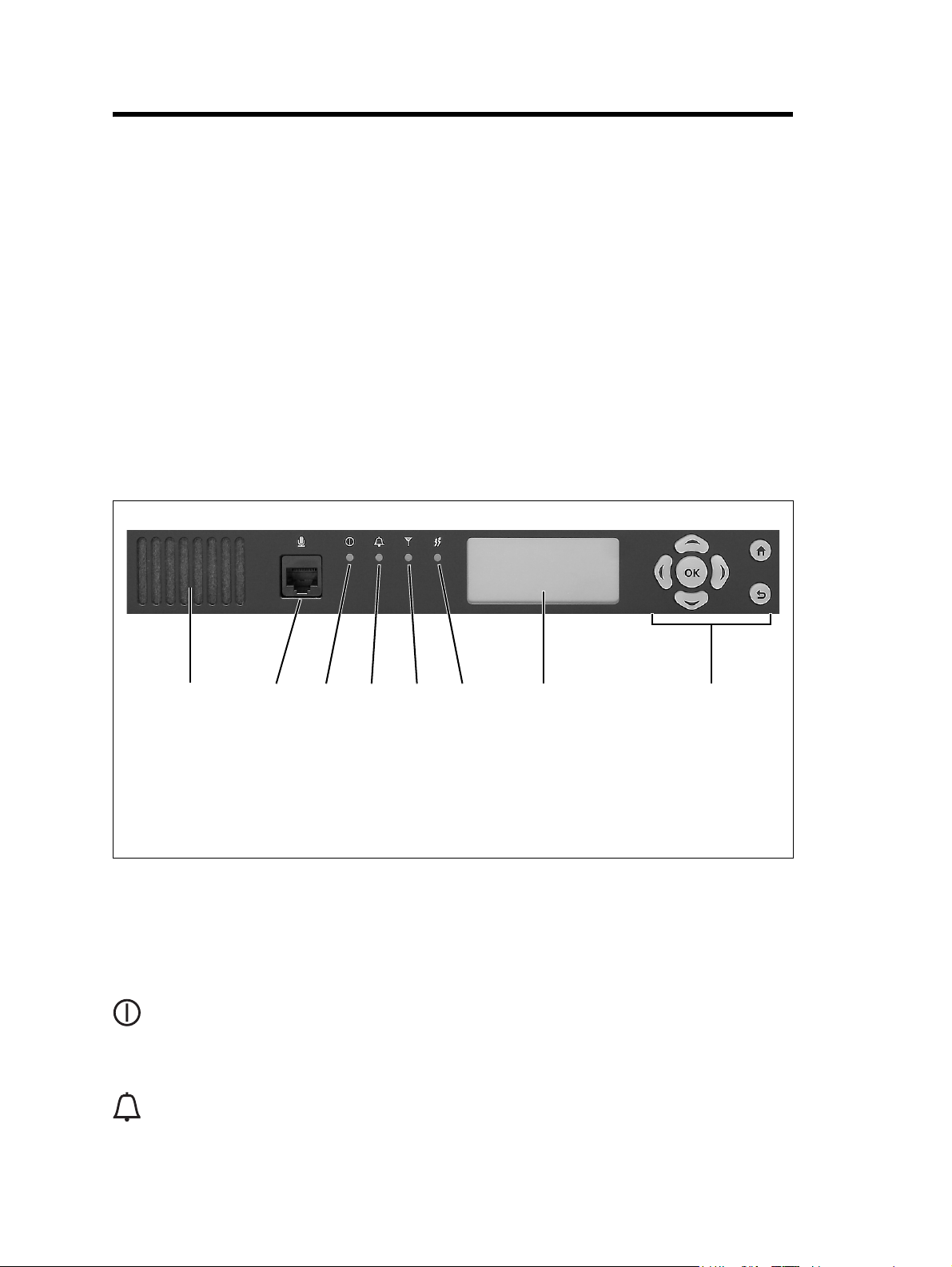
3.1 Front Panel
The user controls and indicator LEDs on the front panel are shown in
Figure 3.1. They allow some manual control over the base station and
monitoring of its operational status.
Notice If there is more than one reciter in a subrack, inputs from all
reciters are summed to drive the front panel LEDs.
Figure 3.1 Operating controls on the control panel
b c
d
e
b
speaker
b
microphone connector
c
power LED
d
alarm LED
e
Speaker and
Microphone
Connector
Power LED The green power LED is lit when power is supplied to the subrack.
Alarm LED The red alarm LED will flash at a rate of 2 to 5Hz when an alarm has been
c
de
The speaker and microphone connector are not currently used.
generated by any of the base station modules. It will continue to flash until
the alarm is canceled or the fault is fixed. Note that only those alarms which
are enabled using the web interface will cause this LED to flash.
gi
f
receive LED
f
transmit LED
g
keypad
h
display
i
h
38 Operation TB9400 Installation and Operation Manual
© Tait International Limited November 2018
Page 39

LED Description
Flashing One or more faults are present.
On (steady) A base station is in Offline mode, and no faults are present.
Off A base station is in Online mode, and no faults are present.
Receive LED
f
The amber receive LED indicates whether the base station is receiving a
valid RF signal (on one or both logical channels in P25 Phase 2 operation).
LED Description
On (steady) A base station is receiving a valid RF signal.
Off A base station is not receiving a valid RF signal.
Transmit LED The amber transmit LED is lit while the transmitter is transmitting.
g
Keypad The keypad is used to navigate the base station’s menus, enter text, and to
h
adjust the contrast of the display. The complete list of menu items is
provided in “Menu Map” on page 41.
If required, the keypad can be disabled in the web interface to prevent
access to the base station via the front panel menus (see “Subaudible
Signaling” on page 99).
TB9400 Installation and Operation Manual Operation 39
© Tait International Limited November 2018
Page 40

Key Name Function
i
Display
OK
left and right
arrow keys
scroll keys
OK
home
return ■ Returns to the previous menu.
■ Move the cursor to the left or right when entering text. Moving the
cursor beyond the end of a line will return it to the other end of the same
line.
■ Decrease or increase the contrast in the Display Contrast screen.
■ Scroll up and down through a list of menu items.
■ Scroll up and down through the list of available characters when
entering text.
■ Increase or decrease the contrast in the Display Contrast screen.
■ Selects the highlighted menu item.
■ Confirms any adjustments made and exits to the previous menu.
■ When setting the IP address, moves the cursor down one line. When all
the IP addresses are confirmed, exits to the previous menu.
■ Returns to the home screen from any other menu.
■ Moves the cursor up one line in the IP address screen. When the top
line is reached, pressing again returns to the previous menu.
The display is used in conjunction with the keypad to access the base
station’s menus. It allows the technician to configure the IP address of each
reciter (refer to “Setting the IP Address” on page 84), and to set the contrast
of the display (see below).
After the base station is powered up, the display shows “Please wait...”
while the base station is starting up, followed by the home screen when the
start-up process is complete. The home screen shows four lines of userdefined text, which can be entered via the web interface (Identity > Identity
> Base Station Identity).
From the home screen press an arrow key, a scroll key or OK to go to the
base station menu. The display returns to the home screen from any other
screen 30 seconds after the last key press. Press any key to turn on the
backlight. The backlight turns off 30 seconds after the last key press.
If the keypad has been disabled, pressing an arrow key, a scroll key or
OK will cause the display to show “Keypad Disabled”.
Set the display contrast as follows:
1. From the base station menu select Modules > Front Panel > Contrast.
2. To increase the contrast, press the right arrow or scroll up key. To
decrease the contrast, press the left arrow or scroll down key.
When the contrast is set to the required level, press OK to save the changes
and exit the menu.
40 Operation TB9400 Installation and Operation Manual
© Tait International Limited November 2018
Page 41

Menu Map
Home Screen
The menu map below shows the menu items available in this release of the
base station.
Notice The menu map shown is for a single base station. The menu
items available in your base station will depend on which modules are
present in the subrack, and whether the keypad has been disabled (refer
to “Subaudible Signaling” on page 99).
Base Station
Modules
Modules
Reciter 1
Front Panel
Reciter 1
View Reciter 1 Address
Edit Reciter 1 Address
Front Panel
Contrast
View Reciter 1 Address
IP: 172.025.198.043
MASK: 255.255.000.000
GW: 172.025.002.251
Edit Reciter 1 Address
IP: 172.025.198.043
1
MASK: 255.255.000.000
GW: 172.025.002.251
Contrast
TB9400 Installation and Operation Manual Operation 41
© Tait International Limited November 2018
Page 42

3.2 Module Indicator LEDs and Switches
Additional status information is displayed by LEDs in individual modules.
The PMU also has switches that let you turn the AC and DC modules off.
3.2.1 Reciter and Receiver
Front View The indicator LEDs on the front of the reciter or receiver are visible
through a slot in its front panel.
Figure 3.2 Indicator LEDs on the front of the reciter and receiver
b
Reciter Receiver
indicator LEDs
b
These LEDs provide the following information about the state of the reciter
or receiver:
■ steady green - the reciter or receiver is powered up
■ flashing red - one or more alarms have been generated; you can use the
web interface to find out more details about the alarms.
42 Operation TB9400 Installation and Operation Manual
© Tait International Limited November 2018
Page 43
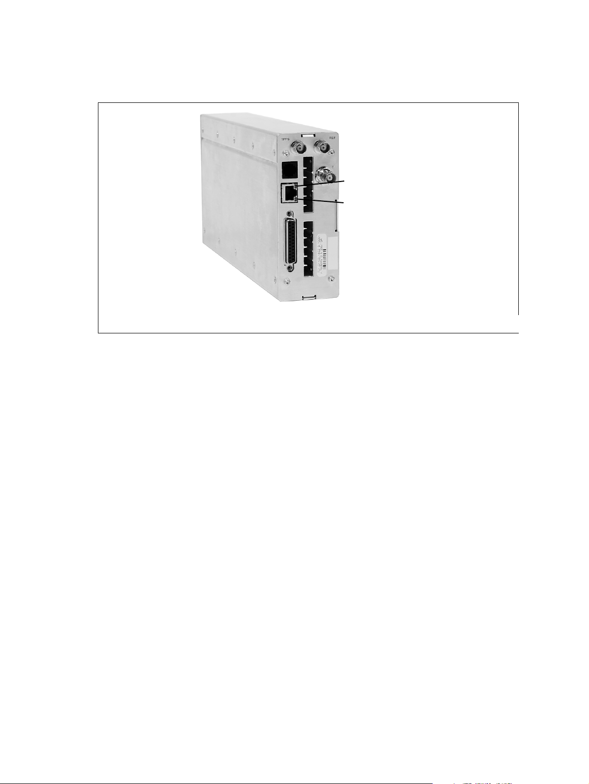
Rear View
Figure 3.3 Indicator LEDs on the rear of the reciter and receiver
The indicator LEDs on the rear of the reciter and receiver are on the
Ethernet connector.
b
c
10Base-T Ethernet Connector LED (green)
b
100Base-T Ethernet Connector LED (amber)
c
10Base-T Ethernet
Connector LED
(green)
100Base-T Ethernet
Connector LED
(amber)
These LEDs provide the following information about the state of the reciter
and receiver:
The green ethernet connector LED will flash if the connection is running at
10 Mbits/s and data is being transmitted across the Ethernet interface.
The amber ethernet connector LED will flash if the connection is running
at 100 Mbits/s. It will be steady amber if the Ethernet interface is
connected.
TB9400 Installation and Operation Manual Operation 43
© Tait International Limited November 2018
Page 44
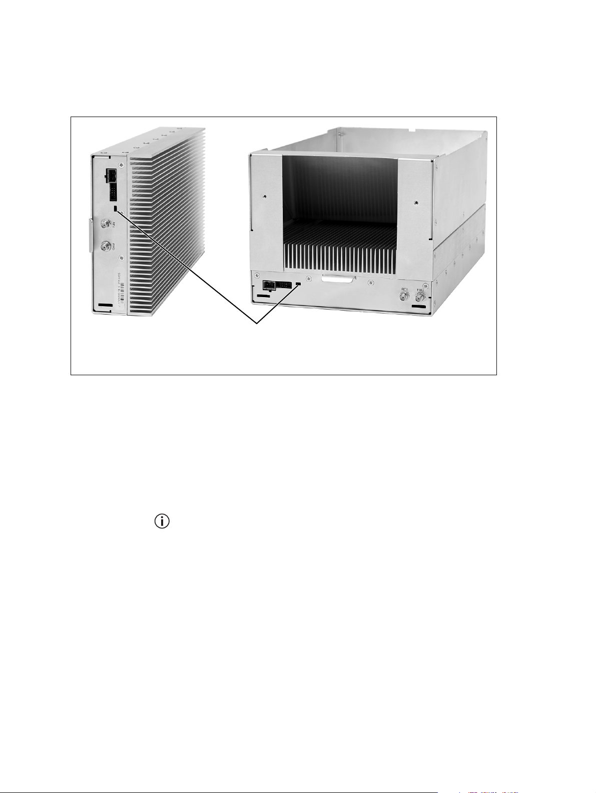
3.2.2 PA
The indicator LEDs on the PA are visible through a slot in its front panel.
Figure 3.4 Indicator LEDs on the PA
50W PA 100W PA
b
indicator LEDs
b
Indicator LEDs These LEDs provide the following information about the state of the PA:
■ steady green - the PA is powered up
■ flashing green - the PA has no application firmware loaded or activated;
you can use the web interface to download or activate the firmware; also
see “Subaudible Signaling” on page 99
■ flashing red - one or more alarms have been generated; you can use the
web interface to find out more details about the alarms.
The alarm LED will flash whenever an alarm is generated, whether or
not this alarm has been disabled via the web interface.
44 Operation TB9400 Installation and Operation Manual
© Tait International Limited November 2018
Page 45
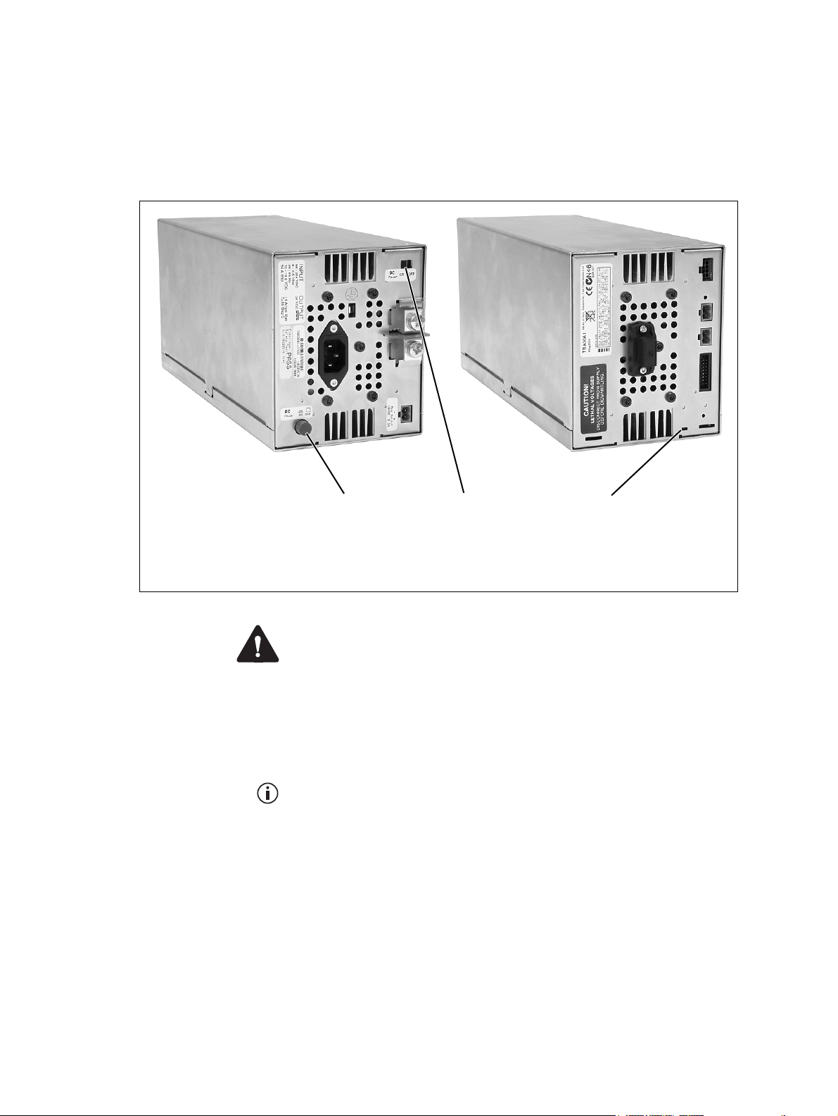
3.2.3 PMU
The only controls on the PMU are the on/off switches on the rear panel for
the AC and DC modules, and the indicator LEDs visible through a slot in
its front panel.
Figure 3.5 Operating controls on the PMU
rear view
AC module on/off switch
b
DC module on/off switch
c
AC Module On/Off
Switch
DC Module On/Off
Switch
front view
bc
indicator LEDs
d
d
Warning The AC and DC module on/off switches do not totally
isolate the internal circuitry of the PMU from the AC or DC power
supplies. You must disconnect the AC and DC supplies from the
PMU before dismantling or carrying out any maintenance.
This switch turns the AC input to the PMU on and off. Note that this switch
breaks only the phase circuit, not the neutral.
The red button remains “out” whether on or off.
This switch turns the DC output from the PMU on and off. Note that this
switch does not disconnect power from the DC converter itself. It disables
the converter by switching off its control circuitry. Even when the DC
converter is off, the DC input is still connected to its power circuitry.
The switch is recessed to prevent the DC module being accidentally
switched off.
Indicator LEDs These LEDs provide the following information about the state of the PMU:
TB9400 Installation and Operation Manual Operation 45
© Tait International Limited November 2018
Page 46

■ steady green - the PMU is powered up
■ flashing green - the PMU has no application firmware loaded or
activated; you can use the web interface to download or activate the
firmware; also see “Subaudible Signaling” on page 99
■ flashing red - one or more alarms have been generated; you can use the
web interface to find out more details about the alarms
■ flashing red and green - the PMU is in battery protection mode; check
that the battery voltage is above the configured minimum startup
voltage; also check that the minimum startup voltage is configured
correctly.
The alarm LED will flash whenever an alarm is generated, whether or
not this alarm has been disabled via the web interface.
46 Operation TB9400 Installation and Operation Manual
© Tait International Limited November 2018
Page 47

4Installation
This chapter provides information on the site requirements for your
TB9400 equipment and also describes how to install the base station in a
standard 19 inch rack or cabinet.
If this is your first time installing a TB9400 base station, we recommend
that you read the entire chapter before beginning the actual installation.
TB9400 Installation and Operation Manual Installation 47
© Tait International Limited November 2018
Page 48

4.1 Before You Begin
4.1.1 Equipment Security
The security of your base station equipment is a high priority. If the site is
not fully secure, the base station should at least be locked in a secure,
ventilated cabinet to prevent unauthorized access.
4.1.2 Grounding and Lightning Protection
Electrical Ground The base station modules are grounded by physical contact between the
module case and the subrack. To ensure a good ground connection you
must tighten each module retaining clamp securely (refer to “Final
Reassembly” on page 115 for the correct torque).
A threaded grounding connector is provided on the rear of the subrack for
connection to the site ground point (refer to “Connecting Up the Base
Station” on page 70 for more details).
Lightning Ground It is extremely important for the security of the site and its equipment that
you take adequate precautions against lightning strike. Because it is outside
the scope of this manual to provide comprehensive information on this
subject, we recommend that you conform to your country’s standards
organization or regulatory body.
4.1.3 Equipment Ventilation
Always ensure there is adequate ventilation around the base station (refer
to “Cabinet and Rack Ventilation” on page 49).
Notice Do not operate it in a sealed cabinet. You must keep the
ambient temperature within the specified range, and we strongly recommended that you ensure that the cooling airflow is not restricted.
Notice The cooling fans are mounted on the front panel and will only
operate when the panel is fitted correctly to the front of the subrack. To
ensure adequate airflow through the base station, do not operate it for
more than a few minutes with the front panel removed (e.g. for servicing
purposes).
4.1.4 Ambient Temperature Sensor
The ambient temperature reading for the base station is provided by the
temperature sensor located on the front panel circuit board.
48 Installation TB9400 Installation and Operation Manual
© Tait International Limited November 2018
Page 49

4.1.5 Cabinet and Rack Ventilation
The cooling airflow for the subrack enters through the front panel and exits
at the rear. For optimum thermal performance, the heated air that passes
through a base station must never be allowed to re-enter the air intakes on
the front panel. Any space at the front of the cabinet not occupied by
equipment should be covered by a blanking panel. Refer to Figure 4.1 on
page 50.
Equipment installation should observe the following guidelines:
■ The recommended maximum number of subracks in a 38U cabinet is
five as shown in Figure 4.1 on page 50.
■ Any space at the front of the cabinet not occupied by equipment should
be covered by a blanking panel. Refer to Figure 4.1 on page 50.
■ Subrack placement in the cabinet should include a 2U gap at the top of
the cabinet.
■ To allow enough cooling airflow through a cabinet-mounted base
station, the cabinet should allow for 50 cu.ft/min for each subrack
(0.024 cu.m/s).
■ To ensure adequate ventilation, the cabinet should have a vent at the top
with an area of approximately 23in
area of ventilation per subrack at the rear of the cabinet behind each
subrack.
■ The maximum ambient temperature at the base station front panels must
not exceed +140°F (+60°C).
2
(150cm2) per subrack, or a similar
TB9400 Installation and Operation Manual Installation 49
© Tait International Limited November 2018
Page 50

Figure 4.1 Typical cabinet ventilation requirements
b
8in
(20cm)
side view front view
2U
c
top view
≥7in
(≥17.5cm)
e
d
c
ventilation slots
b
blanking panels
c
50 Installation TB9400 Installation and Operation Manual
airflow entry
d
airflow exit path
e
© Tait International Limited November 2018
Page 51

4.2 Unpacking and Moving the Subrack
The subrack is packed in a strong corrugated cardboard carton with top and
bottom foam cushions. To prevent personal injury and damage to the
equipment, we recommend that two people unpack and move the subrack.
To remove the subrack from the carton, follow the procedure illustrated in
Figure 4.2.
Caution A subrack complete with modules can weigh up to 55lb
(25kg), or up to 62lb (28kg) complete with packaging. We recommend
that you have another person help you unpack and move the equipment.
The TBAA03-16 carrying handles will make it easier to move the
equipment once it has been unpacked. If necessary, remove the modules
from the subrack before moving it (refer to “Replacing Modules” on
page 105). In all cases follow safe lifting practices.
Figure 4.2 Unpacking the subrack
b
e
g
1. Cut the tape securing the flaps at the top of the carton and fold them
flat against the sides
2. Rotate the carton carefully onto its side
ensuring that none of the flaps is trapped underneath.
cd
f
hi
b.
c and then onto its top d,
TB9400 Installation and Operation Manual Installation 51
© Tait International Limited November 2018
Page 52

3. Slide the carton upwards over the foam cushions and lift it away e.
Remove the cushion from the bottom of the subrack
4. Rotate the subrack and cushion carefully over the rear of the subrack
g so that it is the right way up with the cushion on top h. Remove
the cushion from the top of the subrack
i.
f.
Disposal of
Packaging
If you do not need to keep the packaging, we recommend that you recycle
it according to your local recycling methods. The foam cushions are CFCand HCFC-free and may be burnt in a suitable waste-to-energy combustion
facility, or compacted in landfill.
52 Installation TB9400 Installation and Operation Manual
© Tait International Limited November 2018
Page 53
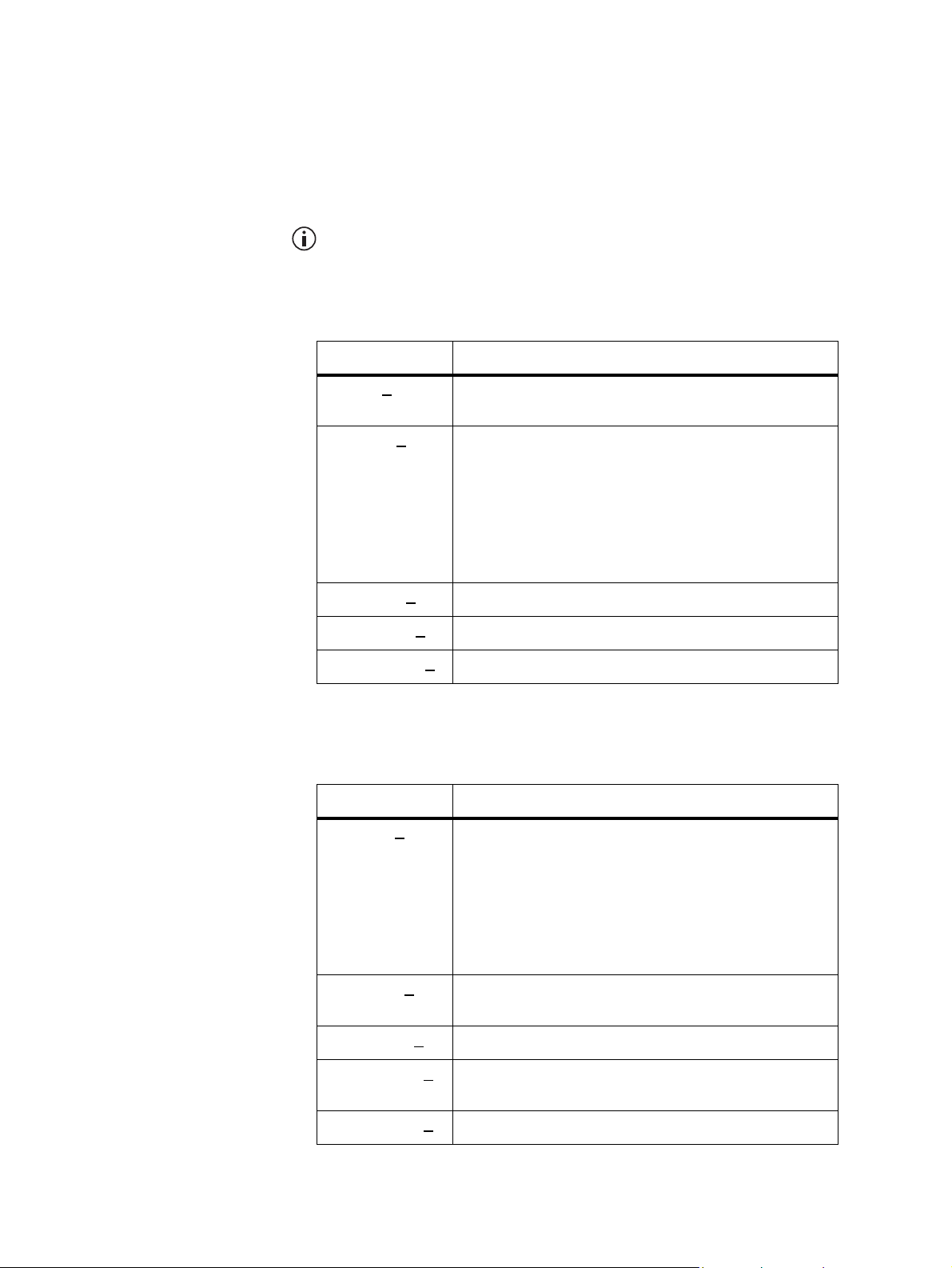
4.3 Identifying the Equipment
You can identify the model and hardware configuration of the TB9400
modules by referring to the product code printed on labels at the rear of
each module. The meaning of each character in the product code is
explained in the tables below.
This explanation of product codes is not intended to suggest that any
combination of features is necessarily available in any one product.
Consult your regional Tait office for more information regarding the
availability of specific models and options.
Reciter and
Receiver Product
Codes
PA Product Codes
Product Code Description
T01-0110X
T01-0110X-X
T01-0110X-XX
T01-0110X-XXX
T01-0110X-XXXX
a. The actual frequency coverage in this band is:
Product Code Description
-XXXX 3 = reciter
4 = receiver
XXX Frequency Band
C = 136MHz to 156MHz
D = 148MHz to 174MHz
J = 378MHz to 420MHz
K = 400MHz to 440MHz
L = 440MHz to 480MHz
M =470MHz to 520MHz
N = 762MHz to 870MHz
XX A = standard
X A = default
A = default
Transmit: 762MHz to 776MHz and 850MHz to 870MHz
Receive: 792MHz to 824MHz
a
Tait Band Identifier
B2 band
B3 band
HH band
H1 band
H2 band
H3 band
K4 band
T01-01121-X
T01-01121-XX
T01-01121-XXXX A = default
T01-01121-XXXX
T01-01121-XXXX
TB9400 Installation and Operation Manual Installation 53
© Tait International Limited November 2018
XXX Frequency Band
C = 136MHz to 156MHz
D = 148MHz to 174MHz
J = 378MHz to 420MHz
K = 400MHz to 440MHz
L = 440MHz to 480MHz
M =470MHz to 520MHz
N = 762MHz to 870MHz
XX A = 50W
B = 100W
A = default
B = no internal Isolator
A = default
Tait Band Identifier
B2 band
B3 band
HH band
H1 band
H2 band
a
H3 band
K4 band
Page 54

a. The actual frequency coverage in this band when used with a K-band
TB9400 reciter is 762MHz to 776MHz and 850MHZ to 870MHz.
PMU Product
Codes
Product Code Description
TBAX
XXX-XXXX 3 = PMU
TBA3X
XX-XXXX 0 = default
TBA3XX
TBA3XXX
TBA3XXX-XXXX 0 = standby power supply card not fitted
TBA3XXX-XXXX 0 = auxiliary power supply board not fitted
TBA3XXX-XXXX 0 = default
TBA3XXX-XXXX
X-XXXX 0 = AC module not fitted
A = AC module fitted
-XXXX 0 = DC module not fitted
1 = 12V DC module fitted
2 = 24V DC module fitted
4 = 48V DC module fitted
1 = 12VDC standby power supply card fitted
2 = 24VDC standby power supply card fitted
4 = 48VDC standby power supply card fitted
1 = 12VDC auxiliary power supply board fitted
2 = 24VDC auxiliary power supply board fitted
4 = 48VDC auxiliary power supply board fitted
0 = default
54 Installation TB9400 Installation and Operation Manual
© Tait International Limited November 2018
Page 55

4.4 Initial Setting Up
Before putting the base station into service, you may want to carry out
some basic functional testing, configuration, and tuning (if required). This
section provides an overview of these procedures:
■ checking that the base station powers up correctly
■ checking the basic functionality of the base station by using the tests
available in the web interface
■ customizing the configuration for the intended installation and
verifying that the configuration is correct
■ changing the root password
■ tuning the base station (if required).
4.4.1 Confirming Operation
Notice Make sure that the RF output is connected to a suitable atten-
uator or dummy load. Do not remove the load while the PA is transmitting as this may damage the PA output stage.
Applying Power 1. Apply power by turning on the PMU.
2. Check that the base station powers up correctly:
■ The front panel display will show “Please wait...” while the base
station starts up (this may take up to two minutes). When the
startup process is complete, the display will show the home
screen.
■ The cooling fans in the front panel will run at full speed for a few
seconds, then run at low speed while the base station starts up,
and then assume standard operation. One or more fans may
operate, depending on the temperature of the modules.
TB9400 Installation and Operation Manual Installation 55
© Tait International Limited November 2018
Page 56

Functional Tests
The following table provides an overview of the tests available using the
web interface. Refer to the Help for full details of these tests.
Test Notes Menu
receiver operation requires a suitable RF source Diagnose > RF Interface > Receiver
transmitter operation requires connection to the
network
synchronized transmit checks the simulcast operation of
a channel group or the
transmitters in it
ping checks the IP connection to
another device with an IP address
NTP query checks if the NTP-based time
synchronization is working
PMU mains failure requires a DC backup supply Diagnose > Subsystems > PMU Control
fan operation checks the operation of each fan
individually
Diagnose > RF Interface > Transmitter
Diagnose > RF Interface > Synchronized
Transmit
Diagnose > Connection > Network
Tests
Diagnose > Subsystems > Fan Tests
56 Installation TB9400 Installation and Operation Manual
© Tait International Limited November 2018
Page 57

4.4.2 Working with Configurations
The Web UI page Tools > Files > Configuration allows you to manage your
base station configuration.
You can do the following:
■ Back up a configuration. This stores a snapshot of the base station’s
current configuration. It is advisable to back up the current
configuration before making significant configuration changes.
■ Upload a configuration. This copies a configuration from your
computer to the base station. You can develop a master configuration
and upload it to all the base stations in the network.
■ Download a configuration. This copies the selected configuration to
your computer so that you can store it.
■ Restore a configuration. This activates the selected configuration after
making it compatible with the current software. You can restore
configurations that have been backed up on the base station.
Users should be aware that the following parameters are not restored on a
base station when a configuration is restored:
■ Keypad enabled
■ Secure shell enabled
■ Receiver number
■ Host name
■ Default channel
■ Operating mode
■ Front panel text lines 1 through 4
■ IP address
■ Subnet mask
■ Gateway address
■ Link speed
TB9400 Installation and Operation Manual Installation 57
© Tait International Limited November 2018
Page 58

4.4.3 Customizing the Configuration
The following steps provide an overview of the process used to configure
the base station with the settings it needs. Refer to the Help for detailed
information.
1. Log in to the base station (refer to “Connecting Your PC to the Base
Station” on page 82 for more details).
2. Select Configure. The base station has many different settings that
can be configured before it is put into operation, such as:
■ channel configurations
■ alarm control and SNMP agent
■ network interfaces
■ channel groups and quality of service
■ channel and signaling profiles
■ CWID
■ miscellaneous items such as minimum battery voltages, fan
control, NTP and package servers.
3. Make the changes needed in each form and click Save. All changes
made in the form will be applied when, and only when, the form is
saved.
Notice Before making changes, you should save the configuration to
your PC or network. This provides a baseline which can be restored to
the base station if the configuration information becomes lost or corrupted.
You should also back up the configuration before downgrading to a different software release. Note that if you downgrade and then upgrade
software, configuration values for new features will disable the feature.
4.4.4 Recommended Configuration Settings
In a dual base station only base station 1 communicates directly with the
PMU and front panel. Therefore the following configuration settings are
recommended for dual base station operation:
■ Disable the “PMU not detected” alarm on base station 2 (Configure >
Alarms > Control > PMU).
■ Disable the “FP not detected” alarm on base station 2 (Configure >
Alarms > Control > Front panel).
4.4.5 Restricted Port Numbers
Certain configuration settings in the base station’s web interface require
you to enter a port number (for example, the trunking interface and channel
groups).
58 Installation TB9400 Installation and Operation Manual
© Tait International Limited November 2018
Page 59

Two ranges of port numbers are unavailable for use with the base station.
The web interface will prevent you from entering a number from these
ranges, as explained below.
Restricted Port Numbers Details
0 – 1023 The “well-known ports”, commonly used by other
12000 – 14999 Reserved for internal use in the base station.
4.4.6 Changing the Root Password
Notice The following procedure can be carried out only if secure
shell access (SSH) is enabled. Secure shell access to the base station is
disabled by default from version 1.40 onwards. To enable SSH, select
Tools > Settings > Secure shell and click Start.
devices in a network. Using a port number in this
range could cause compatibility problems with
other devices.
Using a port number in this range could cause the
base station to malfunction.
The root password to the Linux operating system of the reciter is a possible
security risk. The equipment is delivered with a default password that is
well known. Knowledge of the password could be used to render the
equipment inoperable, for example by deleting files. If you are concerned
about the security risk that this poses, change the password. If Tait provides
support services, they may need to know the password.
Notice If you change the password and then lose it, the equipment
must be returned to Tait. Make sure that you store the password securely
and do not lose it.
The serial port uses the same password.
To change the root password, follow these steps:
1. Log in from your PC to the base station using SSH client software
such as PuTTY. The username is “root” and the default password is
“k1w1”.
2. At the # prompt, enter the command “passwd”.
3. Follow the on-screen instructions.
4. Record the password in a secure location.
Tait networks are deployed with default weak passwords. For security,
Tait strongly recommends changing the default password where applicable.
TB9400 Installation and Operation Manual Installation 59
© Tait International Limited November 2018
Page 60

4.4.7 Tuning the Reciter and Receiver
The following table indicates which bands are manually tuned and which
are electronically tuned:
Band Manual Electronic
B2 ✓ x
B3 ✓ x
HH x ✓
H1 ✓ x
H2 ✓ x
H3 ✓ x
K4 x ✓
In this section “reciter” also applies to the receiver module (receiveonly reciter).
B-Band Before the base station is installed on site, you may need to tune the
receiver front end. The receiver front end requires tuning if the receive
frequency is shifted more than 2MHz away from the previously set
frequency, or the RSSI level of the new frequency is more than 1dB lower
than the RSSI level of the previously set frequency.
The base station receiver signal level diagnostic (Diagnose > RF Interface > Signal Level) offers the ability to verify that the configured
receiver frequency aligns with the receiver tuning.
When the frequency sweep is set to “Use calibrated noise source”, the
resulting curve represents the receiver front end response, and provides
a quick visual check of whether the receiver is optimally tuned. A well
tuned receiver should have the maximum response at the operating frequency. See the online help for more details.
The receiver in the B3-band reciter covers the 148 to 174MHz frequency
band. This is split into two sub-bands: 148 to 159MHz and
159to174MHz.
Each sub-band has its own helical filter (shown in Figure 4.3 below) which
is electronically switched in or out of circuit depending on the frequency
programmed into the reciter. The bandwidth of these helical filters is
approximately ±1.5MHz.
60 Installation TB9400 Installation and Operation Manual
© Tait International Limited November 2018
Page 61

Figure 4.3 Identifying the B-band receiver front end helical filters
B2: 146 to 156MHz
B3: 159 to 174MHz
B2: 136 to 146 MHz
B3: 148 to 159 MHz
TB9400 Installation and Operation Manual Installation 61
© Tait International Limited November 2018
Page 62

To check the RSSI level and tune the receiver front end (if required), follow
these steps:
1. Remove the reciter from the subrack and reconnect the system
control bus cable to power up the module.
Tait can provide extender cables (TBC Reciter Power Cables) to enable
tuning with a subrack or from a bench power supply. To order these, the
part number is T01-01150-0001.
2. Log in to the reciter and select Monitor > Interfaces > RF Interface.
For information on connecting directly to the reciter, refer to “Local
Connection to a Base Station” on page 85.
3. Feed a signal at the currently tuned receive frequency and at a level
of –80dBm into the reciter’s RF input. Check that the RSSI reading
on the RF Interface page is –80dBm ±1dB.
4. Set the reciter to the new receive frequency.
5. Change the RF input signal to the new receive frequency at
–80dBm. Check that the RSSI reading is – 80dBm ±1 dB. If it is, the
receiver front end does not require tuning. If it is not, go to the next
step.
1
6. Using the Johanson tuning tool
the new frequency (as shown in Figure 4.3) to obtain a peak RSSI
reading. This reading should be within 1dB of the reading at the
previous frequency.
Adjust the center resonator of the filter first, followed by the two
outer resonators (in any order). Each resonator should require
approximately the same amount of adjustment when tuning.
A change in frequency of 5MHz requires approximately one turn of the
tuning slug. If tuning to a lower frequency, turn the slug clockwise; for
a higher frequency, turn the slug anti-clockwise.
7. Change the RF input signal and the reciter’s receive frequency to
0.5MHz above and below the required frequency and check that the
RSSI reading does not drop by more than 0.5dB from the reading at
the required frequency.
8. Recalibrate the RSSI at the new frequency (Calibrate > Reciter >
RSSI).
If you wish to confirm the accuracy of the tuning procedure, carry out a
sensitivity measurement at the new frequency.
, adjust the correct helical filter for
1. Included in the TBA0ST2 tool kit. Also available separately as part number 937-00013-00.
62 Installation TB9400 Installation and Operation Manual
© Tait International Limited November 2018
Page 63

H-Band
Before the base station is installed on site, you may need to tune the
receiver front end. The receiver front end requires tuning if the receive
frequency is shifted more than 5MHz away from the previously set
frequency, or the RSSI level of the new frequency is more than 1dB lower
than the RSSI level of the previously set frequency.
Tait can provide extender cables (TBC Reciter Power Cables) to enable
tuning with a subrack or from a bench power supply. To order these, the
part number is T01-01150-0001.
The receiver in the H-band reciter covers one of the following frequency
sub-bands, depending on the model:
■ H1 - 400 to 440MHz
■ H2 - 440 to 480MHz
Each sub-band uses the same helical filter (shown in Figure 4.4 below).
The bandwidth of the helical filter is approximately ±5MHz.
The HH-band variant has no helical filter, so does not require tuning.
Figure 4.4 Identifying the H-band receiver front end helical filter
H-band helical filter
To check the RSSI level and tune the receiver front end (if required), follow
these steps.
1. Remove the reciter from the subrack and reconnect the system
control bus cable to power up the reciter.
2. Log in to the reciter and select Monitor > Interfaces > RF Interface.
For information on connecting directly to the reciter, refer to “Local
Connection to a Base Station” on page 85.
TB9400 Installation and Operation Manual Installation 63
© Tait International Limited November 2018
Page 64

3. Feed a signal at the currently tuned receive frequency and at a level
of –80dBm into the reciter’s RF input. Check that the RSSI reading
on the RF Interface page is –80dBm ±1dB. Note this reading.
4. Set the reciter to the new receive frequency.
5. Change the RF input signal to the new receive frequency at
–80dBm. Check that the RSSI reading is – 80dBm ±1 dB. If it is, the
receiver front end does not require tuning. If it is not, go to the next
step.
1
6. Using the Johanson tuning tool
frequency (as shown in Figure 4.4) to obtain a peak RSSI reading.
This reading should be within 1dB of the reading at the previous
frequency.
Adjust the center resonator of the filter first, followed by the two
outer resonators (in any order). Each resonator should require
approximately the same amount of adjustment when tuning.
If tuning to a lower frequency, adjust the slug in (clockwise); for a
higher frequency, adjust the slug out (counterclockwise).
, adjust the helical filter for the new
7. Change the RF input signal and the reciter’s receive frequency to
2MHz above and below the required frequency and check that the
RSSI reading does not drop by more than 0.5dB from the reading at
the required frequency.
8. Re-calibrate the RSSI at the new frequency (Calibrate > Reciter >
RSSI).
If you wish to confirm the accuracy of the tuning procedure, carry out a
sensitivity measurement at the new frequency.
K-Band The K-band reciter does not require tuning.
1. Included in the TBA0ST2 tool kit. Also available separately as part number 937-00013-00.
64 Installation TB9400 Installation and Operation Manual
© Tait International Limited November 2018
Page 65

4.5 Installing the Base Station on Site
4.5.1 General Installation Advice
When installing base stations, it is very important to observe good site
engineering rules. This is especially true when the channels are combined
into a single antenna.
If at all possible, the RF planner should avoid frequency plans in which the
Rx to Tx spacing is an exact multiple of the trunked channel spacing, thus
forcing Tx intermodulation products to fall outside the Rx channels.
Cables and antennas should be of high quality construction. Solid shield
heliax type cables are best, but if braided shield cables must be used for
short distances, their braids must be silver-plated.
When the outputs of more than one transmitter are combined, their voltages
add, and the resulting peak envelope power is not simply the sum of their
powers, but is equal to the power of one of them multiplied by the square
of the number of sources. Cables, components, and hardware must be rated
to withstand the peak envelope power.
During the commissioning process, all transmitters should be activated
together using a diagnostic test tone, while the receiver RSSI is monitored.
There should be no perceptible increase in RSSI while the transmitters are
active.
Base stations may require an external frequency reference, a 1PPS signal,
and an NTP source, depending on the frequency band and type of radio
system.
The following general rules apply:
■ Base stations operating at or above 700MHz require an external
frequency reference to meet the frequency accuracy requirements for
transmitters and receivers.
■ Simulcast transmitters require an external frequency reference and a
1PPS signal so that transmissions can be timed with the required
accuracy. They also require an NTP source. Both the 1PPS and NTP
signals must be derived from a source that is GPS-disciplined. This will
ensure a common timestamp in logs across all units in the system.
■ P25 Phase 2 base stations require an external frequency reference and a
1PPS signal for site alignment of transmitters and receivers. They also
require an NTP source to ensure correct, long-term Phase 2 alignment.
The requirements for P25 Phase 1 systems are described in more detail
below. Also see “Connecting an External Frequency Reference” on
page 77 and “Connecting a 1PPS Source” on page 78.
TB9400 Installation and Operation Manual Installation 65
© Tait International Limited November 2018
Page 66

P25 Phase 1
The requirements for an external frequency reference and a 1PPS signal are
set out in the following table.
Transmit and Receive Receive Only
Band System
B band
H band
K band Non-simulcast
Non-simulcast
Simulcast
Simulcast
External
Reference
✘✘✘✘
✔✔✘ ✘
✔✘✔✘
✔✔✔✘
1PPS
External
Reference
1PPS
An NTP source is also strongly recommended for P25 Phase 1
non-simulcast systems. This will ensure log timestamps are synchronized, which will assist the diagnosis of faults.
Synchronization requirements are more stringent with the introduction
of simulcast and with TDMA in Phase 2. See Technical Note TN-2411a
Providing Synchronization to Tait Networks.
4.5.2 Equipment Required
It is beyond the scope of this manual to list every piece of equipment that
an installation technician should carry. However, the following tools are
specifically required for installing the base station:
■ Pozidriv PZ3 screwdriver for the M6 screws used in the DC input
terminals on the PMU; M6 (0.25in) screws are also used to secure the
subrack to the cabinet in factory-assembled systems
■ Pozidriv PZ2 screwdriver for the M4 screws used to secure the module
retaining clamps, and for the fasteners used to secure the front panel to
the subrack
■ 8mm AF spanner for the SMA connectors, and the subrack ground
connector.
You can also obtain the TBA0ST2 tool kit from your regional Tait office.
It contains the basic tools needed to install, tune, and service the base
station.
66 Installation TB9400 Installation and Operation Manual
© Tait International Limited November 2018
Page 67
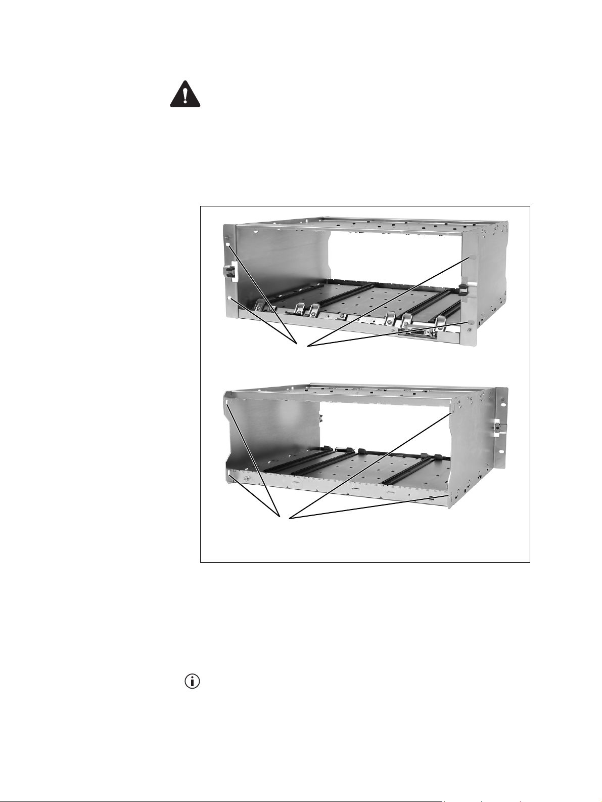
4.5.3 Mounting the Subrack
Caution A subrack complete with modules can weigh up to 55lb
(25kg), or up to 62lb (28kg) complete with packaging. We recommend
that you have another person help you unpack and move the equipment.
The TBAA03-16 carrying handles will make it easier to move the
equipment once it has been unpacked. If necessary, remove the modules
from the subrack before moving it (refer to “Replacing Modules” on
page 105). In all cases follow safe lifting practices.
Figure 4.5 Subrack mounting points
front view
b
rear view
c
main mounting holes - front
b
1. Remove the front panel, as described in “Preliminary Disassembly”
on page 106.
2. Fit the subrack into the cabinet or rack and secure it firmly with an
M6 (0.25in) screw, flat and spring washer in each of the four main
mounting holes
b, as shown in Figure 4.5.
auxiliary mounting holes - rear
c
If you need extra mounting security, additional mounting holes
provided at the rear of the subrack for auxiliary support brackets.
TB9400 Installation and Operation Manual Installation 67
© Tait International Limited November 2018
c are
Page 68
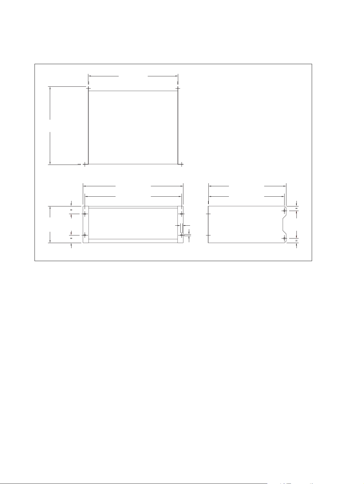
Figure 4.6 below gives the dimensions of the subrack and its mounting
holes.
Figure 4.6 Subrack dimensions
14.8 in
(375.5 mm)
17 in (432 mm)
6.96 in
(176.8 mm)
4 in
(101.6 mm)
19 in (482.6 mm)
18.3 in (465.1 mm)
0.42 in
(10.6 mm)
0.26 in
(6.6 mm)
14.7 in (373.5 mm)
14.37 in (365 mm)
5.25 in
(133.4 mm)
68 Installation TB9400 Installation and Operation Manual
© Tait International Limited November 2018
Page 69

Auxiliary Support
Bracket
TBAA03-13 auxiliary support brackets can be fitted to the rear of the
subrack to provide additional mounting security. Figure 4.7 shows a
standard TBAA03-13 bracket
are not using the Tait cabinet, you may have to make your own brackets to
suit your installation.
Figure 4.7 Auxiliary support bracket
b fitted in a typical Tait cabinet c. If you
b
c
Notice Yo u must fit the auxiliary support brackets if you intend to
transport a cabinet fitted with a fully built-up base station.
We also recommend that you fit the brackets under the following
conditions:
■ when the installation is in an area prone to earthquakes
■ when third party equipment is installed hard up underneath the base
station subrack.
General Cabling We recommend that you try to route all cables to and from the base station
along the side of the cabinet so the cooling airflow is not restricted.
TB9400 Installation and Operation Manual Installation 69
© Tait International Limited November 2018
Page 70

DC Power Cabling
DC power cables should be well supported so that the terminals on the
PMU and on the ends of the cables do not have to support the full weight
of the cables.
Figure 4.8 shows two recommended methods of securing these cables to
prevent straining either set of terminals.
We recommend that you fit the supplied covers to the DC terminals to
protect against accidental shorts.
Figure 4.8 DC power cabling
4.6 Connecting Up the Base Station
This section provides information relevant to the task of connecting up the
various inputs and outputs of the base station.
secure the cables to the
cabinet to support their
weight
70 Installation TB9400 Installation and Operation Manual
© Tait International Limited November 2018
Page 71

4.6.1 Connection Overview
The connections at the rear of a 100W base station are identified in
Figure 4.9. External connections are all located at the rear of the subrack.
Figure 4.9 100W base station inputs and outputs
bcd
e
1@
Reciter 1 PMU
serial RS-232 connector
b
1PPS input
c
external reference frequency input
d
RF input
e
RF output
f
–VDC input
g
fgh
ij1)1!
PA
a
+VDC input
h
auxiliary DC output
i
AC mains input
j
Ethernet interface connector
1)
subrack ground connector
1!
system interface connector
1@
a. Factory use only.
TB9400 Installation and Operation Manual Installation 71
© Tait International Limited November 2018
Page 72
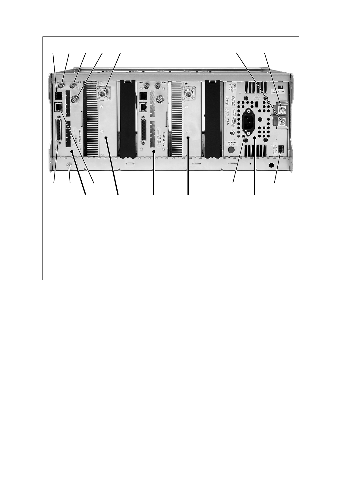
Figure 4.10 50 W base station inputs and outputs
bcd
e
1@
PA 1Reciter 1 PMU
serial RS-232 connector
b
1PPS input
c
external reference frequency input
d
RF input
e
RF output
f
–VDC input
g
fgh
ij1)1!
PA 2Reciter 2
a
+VDC input
h
auxiliary DC output
i
AC mains input
j
Ethernet interface connector
1)
subrack ground connector
1!
system interface connector
1@
a. Factory use only.
72 Installation TB9400 Installation and Operation Manual
© Tait International Limited November 2018
Page 73

4.6.2 Connecting AC Power
The PMU is designed to accept a mains input of 88 to 264VAC at 45 to
65Hz. A standard 3-wire grounded socket outlet must be used to supply the
AC power. The socket outlet must be installed near the equipment and must
be easily accessible. This outlet should be connected to an AC power
supply capable of providing at least 600 W. The requirements of two typical
AC supplies are given in the following table.
Nominal Supply Current Requirement
115 VAC 8 A 10 A
230VAC 4A 6A
a. The actual current consumption of the base station will be lower than these re-
quirements (refer to the Specifications Manual for more information).
Your base station should come supplied
with a power supply cord to connect the
male IEC connector on the PMU to the
local AC supply. The pins of the IEC
connector on the PMU are identified at
right.
Circuit Breaker/Fuse
a
Rating
a
phase
ground
neutral
rear view
TB9400 Installation and Operation Manual Installation 73
© Tait International Limited November 2018
Page 74

4.6.3 Connecting DC Power
The PMU is designed to accept a nominal 12VDC, 24VDC or 48VDC
input (depending on the model) with negative or positive ground. There is
a minimum DC startup threshold to prevent damaging a battery which has
little capacity left.
You must connect the DC supply from the battery to the PMU via a fuse or
DC-rated circuit breaker with the appropriate rating, as shown in the table
below. The circuit breaker must have a contact separation of 3mm, an
interrupt capacity of 1000A or more, and an inrush current capability of at
least 500A for a minimum of 3.5ms.
Notice The inrush current is not affected by the state of the DC module on/off switch on the PMU. This switch does not disconnect power
from the DC converter itself. It disables the converter by switching off
its control circuitry. Even when the DC converter is off, the DC input is
still connected to its power circuitry.
The DC input leads should be of a suitable gauge to ensure less than 3%
voltage drop at maximum load over the required length of lead.
Nominal Supply
Volta ge
12VDC 10VDC to 16.8VDC 60A 2 AWG / 35mm
24VDC 20VDC to 33.6VDC 30A 5 AWG / 16mm
48VDC 40VDC to 60VDC 15A 8AWG / 8mm
a. The actual current consumption of the base station will be lower than these re-
quirements (refer to the Specifications Manual for more information).
b. For a length of 5ft to 6.5ft (1.5 m to 2 m) (typical).
Input Voltage
Range
Circuit Breaker/
Fuse Rating
a
Recommended
Wire Gauge
b
2
2
2
Terminate and insulate the DC input leads to protect them from
accidentally shorting to the subrack if the PMU is removed before the leads
are disconnected. Protective covers for the DC terminals are supplied with
each PMU. We recommend a screw torque of 18– 20lbf·in (2–2.25N ·m).
74 Installation TB9400 Installation and Operation Manual
© Tait International Limited November 2018
Page 75

4.6.4 Connecting the Auxiliary DC Power Output
The PMU can provide an auxiliary DC output from the auxiliary power
supply board. This board is available with an output of 13.65VDC,
27.3VDC, or 54.6VDC (depending on the model), and is current limited to
3A, 1.5A or 750mA respectively. This power supply is permanently on as
soon as the base station has finished powering up, and is available on the
auxiliary output connector on the rear panel.
You can connect multiple auxiliary power supply boards in parallel for
redundancy purposes, or to provide an output greater than 40W. Although
no active current sharing is used, auxiliary boards connected in parallel will
current-share before reaching their power limit. The failure (or switching
off) of one auxiliary board will not load any other paralleled auxiliary
boards in the circuit.
The auxiliary power supply turns off briefly when the PMU restarts
after a firmware upgrade. This interruption may also cause any ancillary
equipment powered from the auxiliary supply to restart. If this is a problem for your system, we recommend connecting auxiliary power supply
boards in parallel to ensure an uninterrupted power supply for the ancillary equipment.
Auxiliary DC Power
Output Cabling
Network elements are supplied with a connector, as shown in Figure 4.11.
You can use this to connect the PMU’s auxiliary DC power output to
another device (refer to “PMU Auxiliary DC Output” on page 116 for the
pin allocations).
Contact your regional Tait office for details on the full range of wiring kits
available.
Figure 4.11 Auxiliary DC power connector
Phoenix MVSTBR2.5HC/2-ST/5.08 female
TB9400 Installation and Operation Manual Installation 75
© Tait International Limited November 2018
Page 76

4.6.5 Connecting RF
Notice Do not remove the load from the PA while it is transmitting
as this may damage the PA output stage. Before disconnecting any RF
cables, put the base station into Offline mode to prevent any transmissions.
The RF input to the base station is via the marked BNC connector on the
rear panel of the reciter. The RF output is via the N-type connector on the
rear panel of the PA (refer to Figure 4.9 on page 71).
Cables and antennas should be of high quality construction. Solid shield
heliax type cables are best, but if braided shield cables must be used for
short distances, their braids must be silver-plated.
Recommendations
for Installing the PA
We recommend the following installation procedures, which should protect
the PA from damage under all but the most extreme operating conditions.
1. Do not connect the PA directly to the antenna. Fit an isolator or
duplexer between the PA and the load. Fit the isolator as close as possible to the RF output connector on the PA. Do not connect any
switching equipment between the isolator and the PA, unless the
switch cannot operate while there is RF present (i.e. the base station
is transmitting).
2. Fit a surge suppressor to the antenna cabling where it enters the
building.
3. Inspect all cables and equipment connected to the base station for
defects.
Ice on the antenna, or a broken antenna, is unlikely to cause damage to the
PA .
Explanation The circuit design of the PA protects the circuitry from high VSWR. This
makes it difficult to damage the RF power device by keying the PA into a
mismatched load, or if the load deteriorates over even a short period of time
(milliseconds).
However, it is possible to damage the device if all the following conditions
happen at the same time:
■ there is a step change in the PA load (for example, the load is removed)
■ the PA is transmitting
■ the feed line loss between the PA and the mismatch is <1dB.
The effect of such conditions is variable: some devices will not be
destroyed, and some may fail after repeated load interruptions.
76 Installation TB9400 Installation and Operation Manual
© Tait International Limited November 2018
Page 77

4.6.6 Connecting an External Frequency Reference
Notice An external reference is required for simulcast operation.
For K4 band, the internal frequency reference accuracy is inadequate, and
an external reference must be used. An external reference is also required
for simulcast and P25 Phase 2. The external reference frequency can be
10MHz or 12.8MHz, with an input level of 300mV
automatically detects the frequency of the external reference and
configures itself accordingly. The stability of this reference should be as
shown below. For more details, see Technical Note TN-2411b Providing
Synchronization to Tait Networks.
to 5Vpp. The reciter
pp
Multicast P25 Phase 1
P25 Phase 1
P25 Phase 2
Simulcast P25 Phase 1
P25 Phase 2
B and H bands
K4 band
All bands
All bands 10 parts per billion
not required
100 parts per billion
100 parts per billion
If an external reference is required, enable the “external reference absent”
alarm (Configure > Alarms > Control).
Use a 50Ω coaxial cable (RG58 or RG223) to connect the external
reference to the base station’s external reference frequency input. You can
daisy-chain up to eight base stations using F-junctions. The maximum
overall cable length is 30m. Terminate the last connection (including single
base stations) with a 50Ω load.
Figure 4.12 Daisy-chaining an external frequency reference input
maximum overall cable
length is 30m
maximum of eight base
station loads on one
frequency reference output
50Ω termination
(also needed for
single base stations)
TB9400 Installation and Operation Manual Installation 77
© Tait International Limited November 2018
Page 78
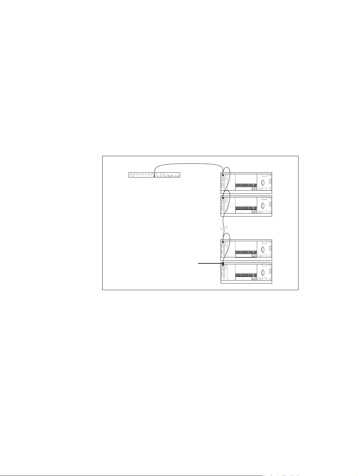
4.6.7 Connecting a 1PPS Source
A 1PPS signal is required for simulcast and P25 Phase 2 base stations. Use
coaxial cable (RG58 or RG223) to connect the source to the base
a 50Ω
station’s 1PPS input. You can daisy-chain up to eight base stations using Fjunctions. We recommend that the cable length between the first and last
load is kept to a minimum. This will reduce any propagation variation
between base stations. The maximum overall cable length is 30m.
Terminate the last connection (including single base stations) with a 50 Ω
resistor, otherwise reflections of the 1PPS pulse may occur.
Notice If 1PPS is used then 1PPS and NTP must both be derived
from the same time base. Normally this will be a GPS disciplined
source.
Figure 4.13 Daisy-chaining a 1 PPS input
The longest length of cable must be between
the source and the first base station
use short lengths of cable
between each base station
maximum of eight base station
loads on one 1PPS output
50Ω termination
(also needed for
single base stations)
78 Installation TB9400 Installation and Operation Manual
© Tait International Limited November 2018
Page 79

4.6.8 Ethernet Connection
The RJ-45 socket on the reciter’s rear panel provides the 10-BASE-T or
100-BASE-T Ethernet connection to the other devices in the network. Use
a Cat-5 cable to connect this socket to the Tait Network via a router or
switch.
The Web UI allows you to set the Ethernet port speed auto-negotiation to
10/100 Mbit/s or to negotiate a maximum 10 Mbit/s. Tait recommends that
you keep the port speed at the factory default setting of 10 Mbit/s. The
reciter hardware and software are scaled to meet the performance
requirements of processing multiple voice streams along with supervisory
control and management communications. 10 Mbit/s is ample for those
requirements. The 10/100 Mbit/s setting is provided for compatibility
reasons, but it is possible under high traffic conditions at 100 Mbit/s for
traffic arriving at the reciter at the full rate within a small timing window
to overflow internal buffers and therefore suffer packet loss. If you set the
port speed to 100 Mbit/s and observe QoS lost packet alarms, then review
your Ethernet port speed settings.
With the port speed at 10 Mbit/s it is particularly important to set the voice
QoS on the reciter port of your site router or switch to a strict priority queue
policy - which is the same policy that you should also be setting for your
site link ports. The default QoS settings restrict the voice bandwidth to 1/
25th of the port speed which is smaller than the required bandwidth for
typical systems at 10 Mbit/s.
If necessary, refer to “Ethernet Connector” on page 116 for a list of
Ethernet connection pin allocations.
TB9400 Installation and Operation Manual Installation 79
© Tait International Limited November 2018
Page 80

4.6.9 Connecting General Purpose Inputs and Outputs
General purpose inputs and outputs are connected via the DB-25 connector
on the rear panel of the base station.
The pin allocations for the DB-25 connector are given in the following
table: Note that not all pins are used in this release of the base station.
Pin Signal Name Signal Type Notes
1
2
3 reserved for future use
4
5
6
B
1$
C
1%
D
1^
E
1&
F
1*
G
1(
H
2)
I
2!
J
2@
1)
2#
1!
2$
1@
2%
1#
external view
7
8
9
10
11 digital in 1 input 5V TTL logic
12 digital in 2
13 +5.2VDC output power output maximum current 200mA
14 digital in 3 input 5V TTL logic
15 digital in 4
16 digital in 5
17 digital in 6
18 digital in 7
19 digital in 8
20 digital in 9 isolated keying input
21 digital in 10
22 digital in 11 isolated gate output
23 digital in 12
24 not used reserved for future use
25 ground ground
active state configurable
(active high vs active low)
active state configurable
(active high vs active low)
■
80 Installation TB9400 Installation and Operation Manual
© Tait International Limited November 2018
Page 81

5 Working with Base Stations from Your
PC
The web browser on your PC provides a window into the TB9400 base
station. Use it to connect to the base station so that you can monitor,
configure, diagnose, and calibrate it (if required).
This section describes the following:
■ Connecting to the base station, including initially setting things up
■ Working with base station web pages
■ Carrying out basic tasks
This section provides an overview of some aspects of the web interface.
Refer to the Help for detailed instructions.
TB9400 Installation and Operation Manual Working with Base Stations from Your PC 81
© Tait International Limited November 2018
Page 82

5.1 PC Recommendations
We recommend the following PC hardware and software for connecting to
a TB9400 base station:
■ SVGA Monitor (1024 x 768 minimum).
■ Network connection.
■ The base station works with recent versions of most modern browsers.
Refer to the Release Notes for more information on currently supported
browsers.
5.2 Connecting Your PC to the Base Station
You connect to a base station using your web browser. You can view
multiple base stations at once by using multiple browser windows or tabs.
Base stations have a web-based interface that provides the pages you view.
Up to ten users may be logged in to a base station at once.
When loading the web user interface with Internet Explorer, the web
page may go blank. To fix this, refresh the page with the ‘F5’ key.
The base station has three different user access levels: Administrator,
Maintainer, and Monitor. Passwords can be defined for each level. This is
done using the base station’s web interface (Tools > Tools > User
Administration). Refer to the base station Help for more information on
setting user access levels.
Connections to the base station can be authenticated by a remote
(i.e. centralized) service. Refer to “Setting Up Authentication” on page 87
and the base station Help for more information.
82 Working with Base Stations from Your PC TB9400 Installation and Operation Manual
© Tait International Limited November 2018
Page 83

5.2.1 Logging In
1. Enter the base station’s URL into your browser using a secure con-
2. A security warning appears when you connect for the first time.
3. The login screen appears.
nection ( https://). To find out the base station’s IP address, on the
front panel select Modules > Reciter 1 (or 2) > View Reciter 1 (or 2)
Address. To set the IP address, refer to “Setting the IP Address” on
page 84.
Notice If access to this menu has been disabled, you cannot use the
front panel to find out the IP address. Make sure that you store the IP
address securely and do not lose it.
Proceed anyway (refer to “Security Certificates” on page 85).
4. Enter your user name and password. When connecting for the first
time, enter the user name “admin” and password “tbc_admin”.
5. Click Login.
Notice After logging in we recommend that you change the password and username for your own security (refer to “Working with the
Web Interface” on page 88). Make sure that you store your passwords
and usernames securely and do not lose them. They may be needed by
Tait support personnel if assistance is required. Tait cannot retrieve forgotten passwords.
TB9400 Installation and Operation Manual Working with Base Stations from Your PC 83
© Tait International Limited November 2018
Page 84

5.2.2 Setting the IP Address
Before the base station is installed on site, you need to provide it with its
proper IP address. Make sure that you do not lose this address. A quick way
to set the base station’s IP address is to use the front panel, as described
below.
Notice If access to this menu on the front panel has been disabled,
log in to the base station and set the IP address using the web interface
(Identity > Identity > Network Identity).
Notice If the base station is online when changing the IP address, it
is possible that the base station will restart. Tait recommends that all
configuration changes are made after taking the base station offline.
1. Use the front panel display to enter the IP address, subnet mask and
gateway specified for this base station by the IP addressing plan for
the network. From the base station menu select Modules > Reciter 1
(or 2) > Edit Reciter 1 (or 2) Address. If the home screen is showing,
press an arrow key, a scroll key or OK to clear it.
Notice In this screen each octet in the address lines has provision for
three characters. If an octet in the address has less than three characters,
enter one or two leading zeroes so that each position is filled, even
though the zeroes are not part of the address. For example, enter
172.25.163.47 as 172.025.163.047. Leading zeroes are removed when
the address is programmed into the base station.
2. Set each address as described below. Use the left and right arrow
keys to move the cursor across each line in the Addresses screen.
Use the scroll keys to scroll through the available numbers for each
position in a line.
a. Set the IP address and press OK. This moves the cursor to the
next line. To move the cursor back to the previous line, press the
return key.
b. Set the Mask address and press OK.
c. Set the Gateway address and press OK.
d. The display shows “Setting Reciter 1 (or 2) address Please
wait...” while the base station confirms that the addresses are cor-
rect. When this process has finished, the display will show
“
SUCCEEDED” or “FAILED” as appropriate. Press OK to return to
the previous menu.
3. If the process failed, try entering the address again. If it still fails, try
the following:
■ enter the address through the web interface
■ check that the IP address you are trying to enter is not already in
use by another device on the same subnet.
84 Working with Base Stations from Your PC TB9400 Installation and Operation Manual
© Tait International Limited November 2018
Page 85

5.2.3 Security Certificates
You can upload your own security certificates to the base station (Tools >
Settings > Web certificate). If you have installed and configured the
appropriate Certification Authority software, you can issue security
certificates for all base stations. After uploading the certificates to the base
stations, you can configure all maintainers’ web browsers to accept
security certificates from your own Certification Authority.
Before you have uploaded a security certificate to the base station, it
will raise a security warning when your browser connects to it for the
first time. The base station creates a self-signed certificate when the
reciter’s firmware is installed. Your browser raises a security warning
because the security certificate was not issued by a trusted Certification
Authority. The browser has a way of letting you override or bypass the
security warning.
5.2.4 Local Connection to a Base Station
Using a computer on site normally requires the computer to have an IP
address that is compatible with the sub-netting and routing used by the
communications network. Additionally, you may need to connect to a
reciter after removing it from service. In either case, you may have to
change your computer IP address configuration.
To connect the base station to your computer, ensure that your computer is
part of the same subnet as the base station, or has a route to it. Refer to your
operating system provider's help for further information on how to do this.
Base stations leave the factory with default IP address: 192.168.1.2, Subnet
mask: 255.255.255.0. If your base station will still not connect to your PC,
contact your local Tait dealer.
You may need to temporarily disconnect a networked PC from its LAN in
order to establish a direct connection with the base station. A physical
connection is needed as well as an alternate or temporary IP address and
subnet mask.
TB9400 Installation and Operation Manual Working with Base Stations from Your PC 85
© Tait International Limited November 2018
Page 86

5.2.5 Troubleshooting Connection Problems
If the attempt to connect to a base station failed, consider these possible
causes.
1. Your PC is part of your organization’s LAN and does not belong to
the same subnet as the base station. Give the PC a suitable IP address
and subnet mask as described in “Local Connection to a Base Sta-
tion” on page 85.
2. You are attempting to connect to the wrong IP address. Check that
the IP address is correct.
Notice You can quickly check the base station’s IP address via the
front panel, as long as access to this menu has not been disabled.
3. The link to the base station is down. Use ping to check.
4. A connection error may occur if your PC is using the organisation’s
web proxy, but the base station doesn’t have a valid gateway address
allowing it to send responses back to that proxy. Users should ensure
that all network parameters are correct (IP address, network mask
and gateway address). You may have to bypass the proxy in your
organization’s LAN to access the Tait Network. Ask your system
administrator to give you access.
5. JavaScript may be disabled in your browser. If JavaScript is
disabled, your browser will be unable to connect to the base station.
Note that modern browsers normally have JavaScript enabled by
default.
5.2.6 Finding a Lost or Forgotten IP Address
Use the following procedure if an IP address has been lost or forgotten.
1. Mount the reciter in a TB9400 subrack and fit the front panel. Power
up the subrack.
2. On the front panel display select Modules > Reciter 1 (or 2) > View
Reciter 1 (or 2) Address.
86 Working with Base Stations from Your PC TB9400 Installation and Operation Manual
© Tait International Limited November 2018
Page 87

5.2.7 Setting Up Authentication
Connections to the base station can be authenticated by a remote
(i.e. centralized) service (Tools > Settings > Authentication). Two remote
authentication protocols are supported: LDAP and RADIUS.
Notice Only people experienced with the AAA architecture and
authentication protocols should make changes on this page.
Moving logins to a centralized server can provide enhanced security for a
number of reasons, such as:
■ less work is required to manage password-controlled access to all base
stations in a network; you no longer need to change the password in
each base station individually
■ previously used passwords may be excluded from re-use
■ access can be denied after a set number of incorrect passwords is
entered
■ passwords can be set to expire on a certain date
■ remote access to base stations can be globally enabled and disabled as
required for technical staff during the commissioning process.
Once the centralized server logins are set up, we recommend that only one
local administrator login is left on the base station for emergency use
(e.g. when the connection to the server is lost). The password for this
emergency login should be kept secret.
TB9400 Installation and Operation Manual Working with Base Stations from Your PC 87
© Tait International Limited November 2018
Page 88
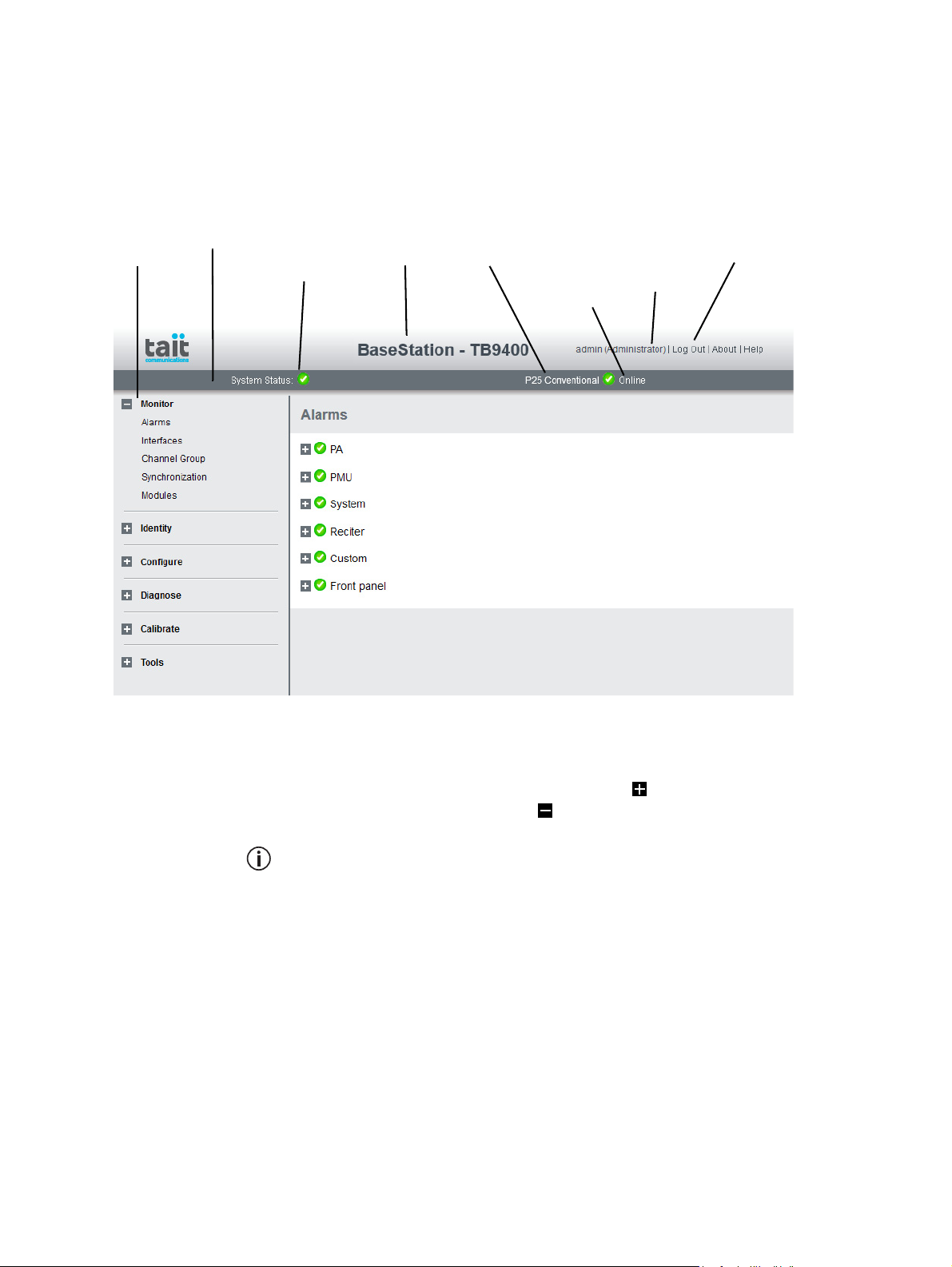
5.3 Working with the Web Interface
This section provides an overview of the web interface. Refer to the Help
for detailed instructions.
When you connect to a base station, the browser displays a page like the
following.
Accordion
menu
Status bar
Alarm status. Click
System Status to
go to the Alarms
screen.
Model and name of
base station
Type of
system
Mode (online or
offline). Click
Mode to go to the
screen where you
can change mode.
Click your user
name to change
your password
and user settings
Click to
disconnect
The accordion menu on the left gives you access to the various pages. Click
a top level item (such as Configure) to open up its menu. Click on a menu
item to display its page, then click on the appropriate tab on that page to
display the required information. Click the + icon ( ) on a menu item to
expand the menu tree and the – icon ( ) to collapse it again.
Using a browser window size smaller than 1024 x 768 may cause some
pages to display incorrectly.
88 Working with Base Stations from Your PC TB9400 Installation and Operation Manual
© Tait International Limited November 2018
Page 89
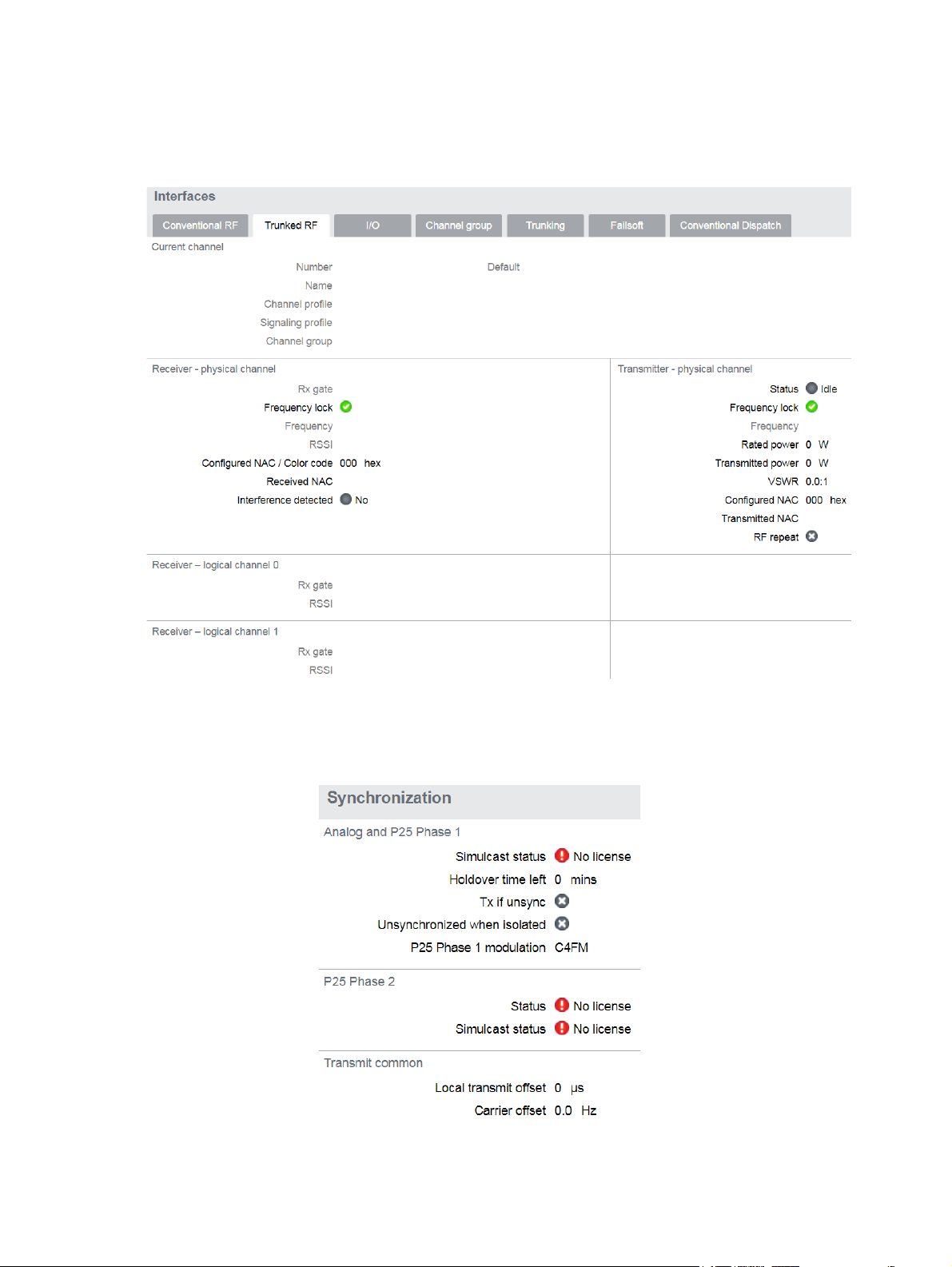
5.3.1 Monitoring Operation
Using the monitoring pages, you can see how the base station is currently
operating. For example, you can see the status of its RF interface (Monitor
> Interfaces > Trunked RF).
If the base station is part of a simulcast network, you can monitor the
simulcast timing of the transmitter and the central voter (Monitor > Synchronization). When connected to the central voter, the browser can
monitor its timing.
TB9400 Installation and Operation Manual Working with Base Stations from Your PC 89
© Tait International Limited November 2018
Page 90
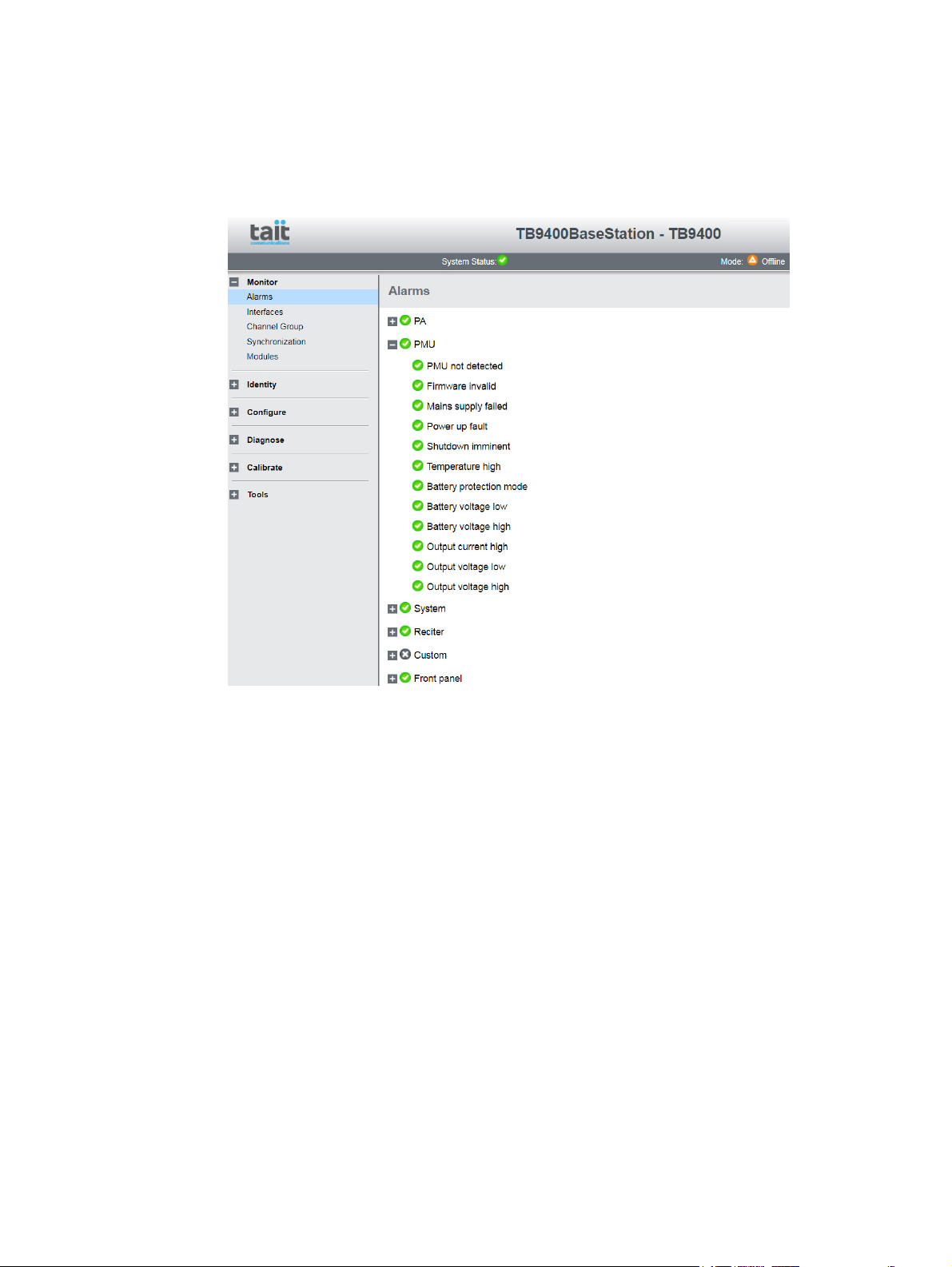
5.3.2 Troubleshooting Alarms
If the Alarm status on the status bar displays red, one or more alarms
have been triggered, and the Alarms menu automatically expands to display the alarm(s). Click Help and navigate to the description of that
alarm
90 Working with Base Stations from Your PC TB9400 Installation and Operation Manual
© Tait International Limited November 2018
Page 91
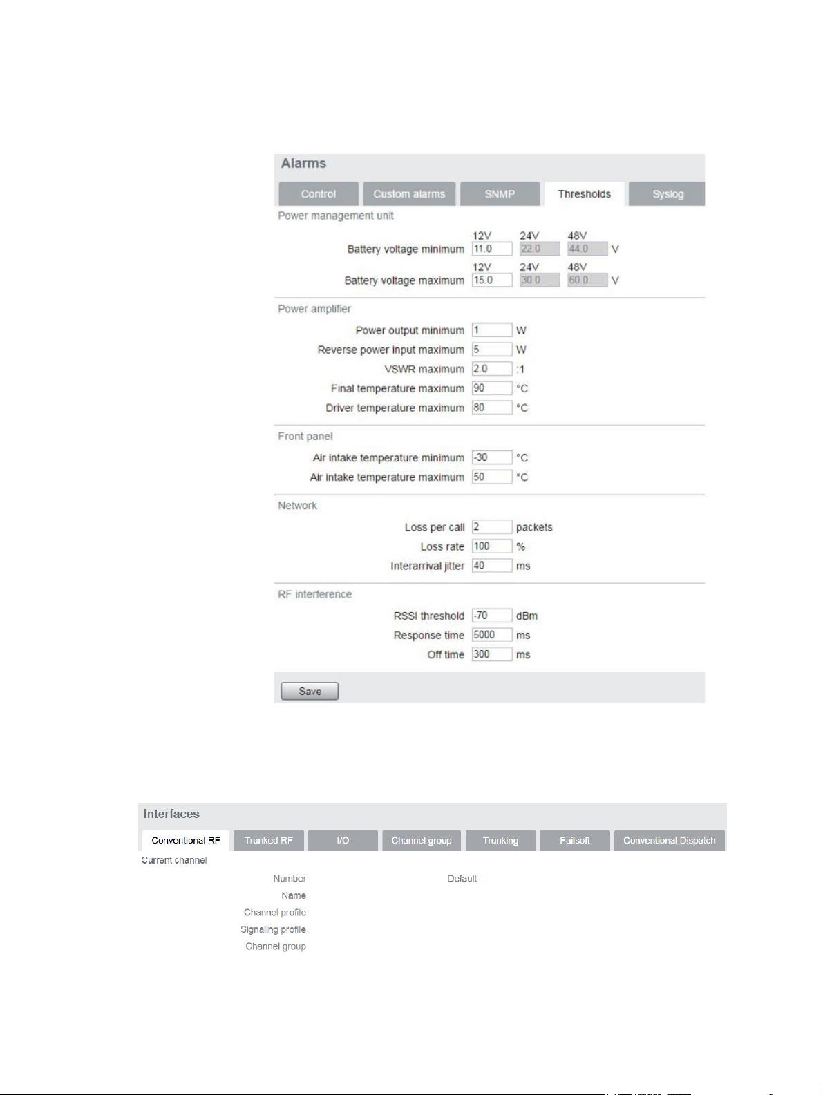
5.3.3 Viewing Configuration Settings
The base station has many configuration settings that personalize it for its
particular role in the network. Some settings, such as those for alarm
thresholds (Configure > Alarms > Thresholds), always apply.
Others are channel-based so that they can be dynamically changed. To view
these, you first need to know the channel on which the base station is
operating. To see the channel number and profiles the base station is using,
select Monitor > Interfaces > Conventional RF.
TB9400 Installation and Operation Manual Working with Base Stations from Your PC 91
© Tait International Limited November 2018
Page 92

Channels can be edited from Configure > Base Station > Channels. To
bring up the edit screen below, select a channel in the table and then click
the Edit button.
92 Working with Base Stations from Your PC TB9400 Installation and Operation Manual
© Tait International Limited November 2018
Page 93
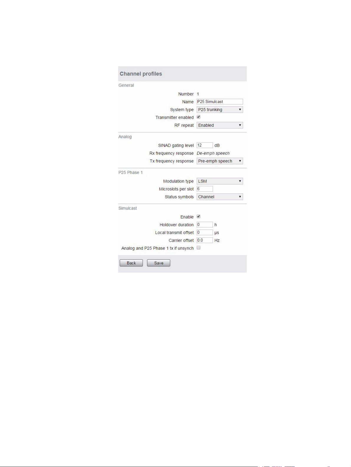
Channel and signaling settings are grouped together in profiles. The RF
monitoring page (see above) shows the channel profile and signaling
profile the channel uses. To view the channel profile settings, select
Configure > RF Interface > Channel Profiles and select the profile you wish
to review or edit.
Proceed in a similar way to view signaling profile and channel group
settings.
TB9400 Installation and Operation Manual Working with Base Stations from Your PC 93
© Tait International Limited November 2018
Page 94

5.3.4 Viewing the Base Station and Network Identity
Each base station in a network has a unique base station and network
identity.
Select Identity > Identity and then Base Station or Network to view details
such as name, receiver number, default channel and network addresses.
Note that the Host name field has a maximum of 63 characters, and may
use the characters a–z, 0–9, dot and hyphen. You cannot use spaces.
The Link speed configuration option enables the Ethernet port speed autonegotiation to 10/100 MBits/s or to negotiate a maximum of 10 Mbits/s.
Under high traffic conditions it is possible for traffic arriving at the reciter
at the full rate (100 Mbits/s) within a small timing window to overflow
internal buffers and therefore suffer packet loss. To minimize this cause of
packet loss a setting of 10 Mbits/s is recommended.
Enter here the four lines of information you want to appear on the home
screen on the front panel display.
94 Working with Base Stations from Your PC TB9400 Installation and Operation Manual
© Tait International Limited November 2018
Page 95

5.4 Basic Tasks
5.4.1 User Settings
Click on your user name in the top right corner of the page to change your
password. Note that this information is stored in the base station, not in
your browser.
5.4.2 Taking the Base Station Offline
You may need to take the base station offline in order to carry out
diagnostic tests or to take it out of service if a fault develops.
1. Click Mode on the status bar (or Select Tools > Tools > Base Sta-
tion).
2. Under Control, select Offline. Click Offline to confirm the change.
In the Status area, the Mode display changes first to “Changing”, and
then to “Offline” ( ).
5.4.3 Troubleshooting Alarms
If the Alarm status on the status bar displays red, one or more alarms have
been triggered, and the Alarms menu automatically expands to display the
alarm(s). Click Help and navigate to the description of that alarm.
TB9400 Installation and Operation Manual Working with Base Stations from Your PC 95
© Tait International Limited November 2018
Page 96

5.4.4 Disabling the Front Panel Keypad
You can disable the front panel keypad to prevent access to the base station
via the front panel menus. Select Configure > Base Station > Miscellaneous
and in the Front Panel area clear the Keypad enabled check box.
Notice If you disable the front panel keypad, you cannot use it to find
out the base station’s IP address. Make sure that you store the IP address
securely and do not lose it.
5.4.5 Preparing to Download Firmware
New versions of base station firmware are remotely downloaded to base
stations from a package server (web server application). You can set up a
single computer to be the central package server for all the base stations on
your network, using a web server of your choice. Tait also provides the
Mongoose
with a temporary package server, such as a laptop.
1
web server as part of the base station firmware package for use
Installing the
Firmware Package
The base station firmware package can be downloaded as a zip file from
the Tait support website.
If you click ‘Cancel’ while downloading a firmware package, it takes
approximately 20 seconds for the cancellation to take effect and for the
base station to respond.
This procedure describes using the Mongoose web server.
The installation procedure copies files into a folder and adds items to the
Windows Start menu (Start > Programs > Tait Applications > TB9400).
From the Start menu you can then access the Help, licenses, manuals and
release notes for each firmware package, and also start Mongoose.
You do not have to install Mongoose to make it work, because it is a
self-contained executable file. Once started, it will run in the background until stopped, or the computer is shut down. Mongoose must
also run from the same folder as the firmware files.
If you are downloading a base station package zip file:
1. Save the zip file to a suitable location on the hard drive of the package server computer.
2. Extract the zip file, then navigate to the root folder and double-click
TB9400.msi to run the Windows installer.
1. Mongoose runs on Windows only.
96 Working with Base Stations from Your PC TB9400 Installation and Operation Manual
© Tait International Limited November 2018
Page 97

Notice Tait recommends that the maximum length of the path to the
location of the extracted files is 100 characters. Using a longer path may
cause the files to be extracted incorrectly.
Setting Up a Central
Package Server
Setting up a
Temporary Package
Server
It is beyond the scope of this manual to describe the exact procedure for
setting up a central package server for any particular network. Tait expects
that each customer will configure their own package server according to the
requirements for their network.
However, you do need to configure each base station with the IP address
and port of the package server computer.
1. Log in to the base station and select Configure > Base Station >
Miscellaneous.
2. Under Package server, enter the IP address and port number of the
package server.
3. Download the firmware as described in the Help.
If you want to use a laptop as a temporary package server, you can
temporarily override the package server IP address and port in each base
station.
1. Run Mongoose on the package server (Start > Programs >
Tait Applications > TB9400 > Mongoose).
2. Windows Firewall may raise a Security Alert about allowing
Mongoose to access your network or the internet.
a. In Windows 7 allow access to private networks.
b. In Windows XP click Unblock.
3. Log in to the base station and select Tools > Firmware > Download.
4. Under Package server, enter the IP address of the laptop. The default
port number is 8080.
5. Download the firmware as described in the Help.
6. If you have trouble with any of the above procedures, please
consider the following points:
■ The firmware download process uses the HTTP protocol. If you
are using a laptop from outside the radio communications
network, make sure that HTTP traffic can get through the
firewall.
■ If Mongoose fails to start, it may already be running, or another
application may be using port 8080.
■ If the error message “Could not find index file” appears when
listing packages, Windows security may be silently blocking
access for Mongoose. Turn off the laptop’s WiFi and temporarily
disable its firewall, then try again.
TB9400 Installation and Operation Manual Working with Base Stations from Your PC 97
© Tait International Limited November 2018
Page 98

5.4.6 Working with Configuration Files
At any time, you can save the current configuration settings as a file
(Tools > Files > Configuration > Backup configuration). This is stored in
the base station, but we recommend that you download it and store it on
your computer as an off-site backup. The base station identity and network
identity are not saved as part of the configuration file.
The following parameters are not restored on a base station when a
configuration is restored:
■ Keypad enabled
■ Host name
■ Default channel
■ Operating mode
■ Front panel text lines 1 through 4
■ IP address
■ Subnet mask
■ Gateway address
■ Link speed
■ SSH enabled
You may want to develop a master configuration and upload it to all base
stations in the network. The master configuration can contain all the
different channel configurations and can be common to all base stations.
The base station identity selects the default channel.
Base stations are delivered with a default configuration which provides
a safe set of values. We recommend that you download it and store it on
your computer as a backup before changing and saving any configuration settings.
You can also generate a report containing all the base station’s
configuration settings (Tools > Files > Configuration > Configuration
report), which can be saved as a text file. We recommend that you do this
when the base station is commissioned. This report can be useful later if
there is a problem with the base station. Comparing the original report with
the later one may highlight changes in configuration that are causing a
problem.
5.4.7 Setting Up Custom Alarms
Each of the base station’s 12 digital inputs can be used to raise a custom
alarm when the input goes high or low. The Custom Alarms form
(Configure > Alarms > Custom Alarms) allows you to assign a name to
each custom alarm.
98 Working with Base Stations from Your PC TB9400 Installation and Operation Manual
© Tait International Limited November 2018
Page 99

The active state of the inputs (active high vs active low) is configured on
(Configure > Base Station > Programmable I/O)
Custom alarms are reported via the web interface and SNMP traps.
Custom alarms provide a warning when an external event activates a digital
input. You can rename any of the available alarms to provide a more
meaningful name, such as “Door open”.
5.4.8 Subaudible Signaling
The purpose of CTCSS and DCS signaling (PL and DPL) is to reject
transmissions from radios that do not belong on the network. It is possible
for digital signals such as DMR to cause falsing with some codes. If
possible, you should avoid the following subaudible codes:
Subaudible Type Code Values
CTCSS (PL) 131.8 Hz
199.5 Hz
233.6 Hz
DCS (DPL) 356
431
723
5.4.9 Checking for Interference on a Receive Channel
You can use the Signal Level page (Diagnose > RF Interface > Signal
Level) to look for sources of interference across a range of receive
frequencies.
The chart on this page has two lines. One shows the current RSSI
measurement for the selected frequency. The second shows a historical
trace of peak RSSI readings on that frequency.
TB9400 Installation and Operation Manual Working with Base Stations from Your PC 99
© Tait International Limited November 2018
Page 100

5.4.10 Configuring Single Base Stations
It is possible to operate the base station as a single base station (for
example, trunked, non simulcast, or as a conventional single repeater). The
following explains the special considerations when configuring single base
stations.
Channel Group
Membership
Although single base stations are not actually part of a channel group, their
channel configurations (Configure > Base Station > Channels) must still
select a channel group (Configure > Channel Group > Channel Groups).
Once a channel group has been selected, the following parameters need to
be configured.
Channel Group IP
Address
Set the channel group to ‘disabled’. Specify 127.0.0.1 as the channel group
IP address. This is the base station’s localhost address and stops it from
attempting to send voice packets to other base stations.
Marshaling
Duration
Single base station operation should not require marshaling. Channel
group and simulcast operation have no meaning for a single transceiver.
Interactions within the software, however, mean that control channel
operation and transmit tail operation both depend on the configured
value. It is recommended to leave the marshaling duration at the value
of 40ms for single base station operation.
Trunking Interface Single base stations need a control connection to their site controller.
A single base station interfaces to the site controller in the same way as the
master base station in a trunked channel group. Select Configure >
Network Interfaces > Trunking to configure this.
5.4.11 Configuring Receive-Only Base Stations
You can program a receiver with the same configuration as a reciter. This
will keep the number of required configuration files to a minimum and, if
possible, re-use existing configuration files.
Transmit information for the receiver will be displayed in the web
interface, but this can be ignored. Also, some polled SNMP parameters,
such as Tx NAC, will return the correct transmitter configuration data, but
none of these parameters is used by the receiver.
5.4.12 Configuring Base Stations in a Channel Group
You can configure the way the base station behaves in its channel group.
Also, qualified network engineers can change DSCP assignments so that
routers and switches provide a different quality of service to different types
of IP packets. For more information on designing and configuring
simulcast channel groups, refer to
100 Working with Base Stations from Your PC TB9400 Installation and Operation Manual
© Tait International Limited November 2018
 Loading...