

Page 1
4 Installation
This chapter describes how to install the TB8100 BSS in a standard 19 inch
rack or cabinet. It also provides some general information on safety
precautions and site requirements. We recommend that you read the entire
chapter before beginning the installation.
4.1 Personal Safety
Lethal Voltages
Warning!! The PMU contains voltages that may be lethal.
Refer to the ratings label on the rear of the
module.
The TB8100 BSS must be installed so that the rear of the PMU is located
in a service access area. Disconnect the mains IEC connector and wait for
five minutes for the internal voltages to self-discharge before dismantling.
The AC power on/off switch does not isolate the PMU from the mains. It
breaks only the phase circuit, not the neutral.
The PMU should be serviced only by qualified technicians. All servicing
should be carried out only when the PMU is powered through a mains
isolating transformer of sufficient rating. We strongly recommend that
the mains power to the whole of the repair and test area is supplied via an
earth leakage circuit breaker.
Explosive Environments
Warning!! Do not operate TB8100 BSS equipment near
electrical blasting caps or in an explosive atmosphere. Operating the equipment in these environments is a definite safety hazard.
Proximity to RF Transmissions
Do not operate the transmitter when someone is standing within 90cm (3ft)
of the antenna. Do not operate the transmitter unless you have checked that
all RF connectors are secure.
TB8100 Installation and Operation Manual Installation 31
© Tait Electronics Ltd June 2003
Page 2
High Temperatures
Take care when handling a PMU or PA which has been operating recently.
Under extreme operating conditions (+60° C [+140° F] ambient air
temperature) the external surfaces of the PMU and PA can reach
temperatures of up to +80° C (+176°F).
4.2 Equipment Safety
ESD Precautions
Important This equipment contains devices which are susceptible to
damage from static charges. You must handle these devices
carefully and according to the procedures described in the
manufacturers’ data books.
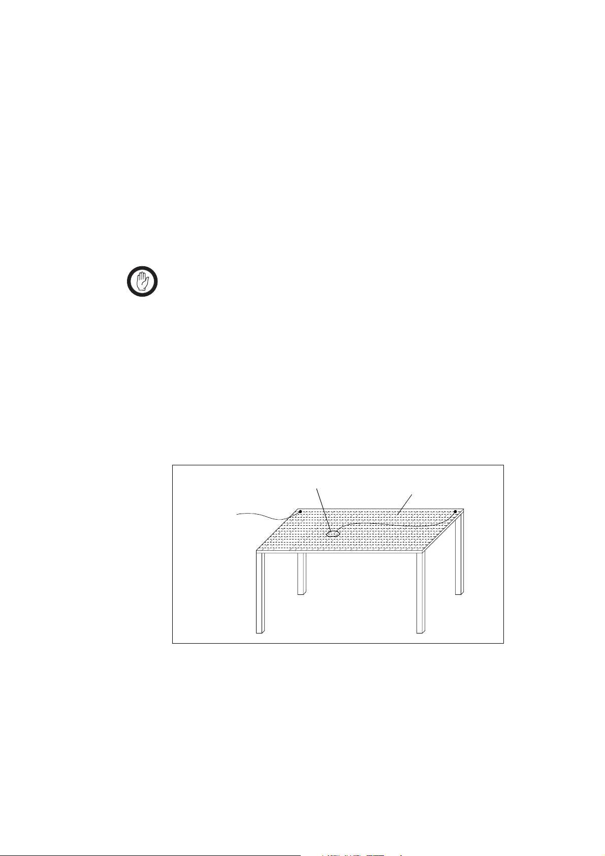
We recommend you purchase an antistatic bench kit from a reputable
manufacturer and install and test it according to the manufacturer’s
instructions. Figure 4.1 shows a typical antistatic bench set-up.
You can obtain further information on antistatic precautions and the dangers
of electrostatic discharge (ESD) from standards such as ESD S4.1-1997
(revised) or BS EN 100015-4 1994.
Figure 4.1 Typical Antistatic Bench Set-up
conductive wrist strap
to building ground
or mains ground
via 1M ohm series
resistor
dissipative rubber
bench mat
Aerial Load
The TB8100 BSS equipment has been designed to operate safely under a
wide range of aerial loading conditions. However, we strongly recommend
that the transmitter should always be operated with a suitable load to prevent
damage to the transmitter output power stage.
32 Installation TB8100 Installation and Operation Manual
© Tait Electronics Ltd June 2003
Page 3

Equipment Grounding
To ensure safe operation the TB8100 BSS equipment must be correctly
grounded as described in these installation instructions.
Installation and Servicing Personnel
The TB8100 BSS should be installed and serviced only by qualified
personnel.
4.3 Regulatory Information
Distress Frequencies
The 406 to 406.1MHz frequency range is reserved worldwide for use by
Distress Beacons. Do not program transmitters to operate in this frequency
range.
FCC Compliance
This device complies with part 15 of the FCC Rules. Operation is subject
to the condition that this device does not cause harmful interference.
Unauthorised Modifications
Any modifications you make to this equipment which are not authorised by
Tait Electronics Ltd may invalidate your compliance authority’s approval to
operate the equipment.
4.4 Environmental Conditions
Operating Temperature Range
The operating temperature range of the TB8100 BSS is –30°C to +60°C
(–22°F to +140°F) ambient temperature. Ambient temperature is defined
as the temperature of the air at the intake to the cooling fans.
Humidity
The humidity should not exceed 95% relative humidity through the
specified operating temperature range.
TB8100 Installation and Operation Manual Installation 33
© Tait Electronics Ltd June 2003
Page 4

Dust and Dirt
For uncontrolled environments, the level of airborne particulates must not
exceed 100µg/m
3
.
4.5 Grounding and Lightning Protection
Electrical Ground
The TB8100 BSS modules are grounded by physical contact between the
module case and the subrack. To ensure a good ground connection you
must tighten each module retaining clamp securely (refer to “Final
Reassembly” on page 53 for the correct torque setting).
A threaded grounding connector is provided on the rear of the subrack for
connection to the site ground point (refer to “Connection” on page 55 for
more details).
Lightning Ground
It is extremely important for the security of the site and its equipment that
you take adequate precautions against lightning strike. While it is outside
the scope of this manual to provide comprehensive information on this
subject, the following guidelines apply:
■ install a suitable lightning rod at the top of the tower and connect it to a
secure ground point with appropriate conductors and connectors
■ position site buildings and equipment within the cone of protection
provided by the grounded tower
■ protect all cables entering the site to prevent lightning energy from
entering site buildings.
4.6 Recommended Tools
It is beyond the scope of this manual to list every tool that an installation
technician should carry. However, the following tools are specifically
required for installing the TB8100 BSS:
■ Pozidriv PZ3 screwdriver for the M6 screws used to secure the subrack
to the rack or cabinet, and also for the DC input terminals on the PMU
■ Pozidriv PZ2 screwdriver for the M4 screws used to secure the module
retaining clamps
■ 0.25in or 6mm flat blade screwdriver for the fasteners used to secure the
front panel to the subrack
■ 8mm AF spanner for the SMA connectors.
34 Installation TB8100 Installation and Operation Manual
© Tait Electronics Ltd June 2003
Page 5

You can also obtain the TBA0ST2 tool kit from your nearest Tait Dealer or
Customer Service Organisation. It contains the basic tools needed to install,
tune and service the TB8100 BSS.
4.7 Ventilation
Always ensure there is adequate ventilation around the TB8100 BSS. Do
not operate it in a sealed cabinet. You must keep the ambient temperature
within the specified range, and we strongly recommended that you ensure
that the cooling airflow is not restricted.
Important The cooling fans are mounted on the front panel and will
only operate when the panel is fitted correctly to the front
of the subrack. To ensure adequate airflow through the
BSS, do not operate it for more than a few minutes with the
front panel removed (e.g. for servicing purposes).
Ambient Air Temperature Sensor
The ambient air temperature reading
for the TB8100 BSS is provided by
the ambient air temperature sensor
PCB
b fitted to the PA control PCB.
The sensor PCB is inserted through
slots in the control PCB and heatsink
to be positioned between the heatsink
fins.
Important If the sensor PCB is to provide accurate ambient tempera-
ture readings, it must have forced airflow and must not
come into contact with the metal of the heatsink fins. Do
not stack PAs with the fins together. It is possible for
the fins on one heatsink to slide between the fins on the
other heatsink. This can damage the sensor PCB, and possibly result in the heatsink fins becoming locked together.
b
TB8100 Installation and Operation Manual Installation 35
© Tait Electronics Ltd June 2003
Page 6

Cabinet and Rack Ventilation
Refer to Figure 4.2 on page 37.
The cooling airflow for the TB8100 BSS enters through the front panel and
exits at the rear of the subrack. For optimum thermal performance, the
heated air that has passed through a BSS must not be allowed to re-enter the
air intakes on the front panel. Any space at the front of the cabinet not
occupied by equipment should be covered by a blanking panel.
To allow enough cooling airflow through a cabinet-mounted BSS, we
recommend the following:
■ an area of at least 150cm
in front of the air intakes for the fans for each subrack; for example,
thirty 6x 85 mm (0.25x 3.3in) slots will allow the recommended airflow
■ a vent in the top of the cabinet with an area of approximately 150cm
■ a 2U gap at the top of the cabinet.
2
(23in
) per subrack, or a similar area of ventilation per subrack at the rear
of the cabinet behind each subrack
2
(23in2) of unrestricted ventilation slots or holes
2
Auxiliary Extractor
Fans
Note The ventilation opening must be unrestricted. If the slots or holes
are covered with a filter, mesh or grille, the open area must be
increased to allow the same airflow as an unrestricted opening.
The maximum ambient temperature entering the cabinet must not exceed
+60°C (+140°F).
If the TB8100 BSS is installed in a rack or cabinet with other equipment
with different ventilation requirements, we recommend that the TB8100 be
positioned below this equipment.
The TB8100 BSS does not require auxiliary extractor fans mounted in the
top of the cabinet. If your cabinet is already fitted with fans, the following
procedures apply:
■ if there are six or more 120mm (4.75in) fans, each capable of extracting
■ if there are fewer than six fans, you must remove them and ensure the
3
160m
per hour (94.2CFM), they must run continuously
vent in the top of the cabinet has an area of approximately 150cm
2
(23in
) per subrack.
2
If you have any other configuration, the performance of your system will
depend on how closely you comply with the TB8100 BSS airflow
requirements described above.
36 Installation TB8100 Installation and Operation Manual
© Tait Electronics Ltd June 2003
Page 7

Figure 4.2 Typical Cabinet Ventilation Requirements
b
20cm
(8in)
top view
side view
≥ 17.5cm
(≥ 7in)
front view
2U
c
c
e
d
c
c
ventilation slots
b
blanking panels
c
TB8100 Installation and Operation Manual Installation 37
© Tait Electronics Ltd June 2003
airflow entry
d
airflow exit
e
Page 8
4.8 Installing the Base Station System
Caution A TB8100 subrack complete with modules can
weigh up to 28kg (62 lb), or up to 30 kg (66 lb) complete with packaging. We recommend that you
remove the modules from the subrack before moving the equipment, or have another person help you
with the lifting. In all cases follow safe lifting practices.
Unpacking the Equipment
Unpacking the
TB8100 BSS
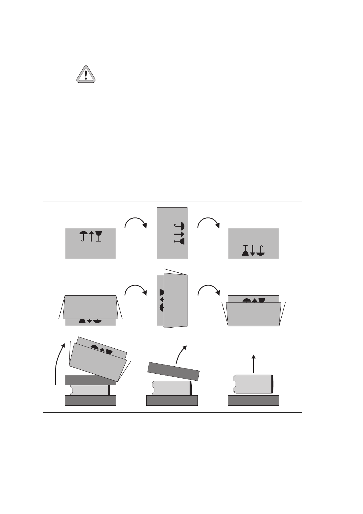
Figure 4.3 Unpacking the TB8100 BSS
The TB8100 BSS is packed in a strong corrugated cardboard carton with
top and bottom foam cushions. To prevent personal injury and damage to
the equipment, we recommend that two people unpack the BSS.
d
bc
ef
ghi
1. Rotate the carton carefully onto its side
2. Cut the tape securing the flaps at the bottom of the carton and fold
them flat against the sides
38 Installation TB8100 Installation and Operation Manual
d.
b and then onto its top c.
© Tait Electronics Ltd June 2003
Page 9

3. Rotate the carton carefully onto its side e, and then onto its bottom
f, ensuring that none of the flaps is trapped underneath.
4. Slide the carton upwards over the foam cushions and lift it away
5. Remove the cushion from the top of the BSS
Disposal of
Packaging
If you do not need to keep the packaging, we recommend that you recycle
it according to your local recycling methods. The foam cushions are CFCand HCFC-free and may be burnt in a suitable waste-to-energy combustion
facility, or compacted in landfill.
Mounting the Subrack
Caution We recommend that you remove the modules from
Figure 4.4 Subrack Mounting Points
out of the other cushion
the subrack before lifting it (refer to “Replacing
Modules” on page 43), or have another person help
you with the lifting.
g.
h and then lift the BSS
i.
front view
b
rear view
c
main mounting holes - front
b
TB8100 Installation and Operation Manual Installation 39
© Tait Electronics Ltd June 2003
auxiliary mounting holes - rear
c
Page 10
1. Remove the front panel, as described in “Preliminary Disassembly”
on page 43.
2. Fit the subrack into the cabinet or rack and secure it firmly with an
M6 screw, flat and spring washer in each of the four main mounting
holes
Note If you need extra mounting security, there are additional mount-
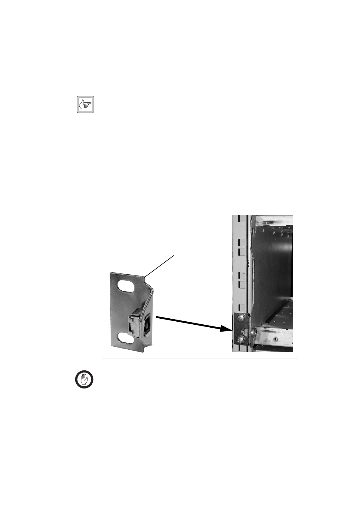
Auxiliary Support Bracket
TBA2140 auxiliary support brackets can be fitted to the rear of the TB8100
subrack to provide additional mounting security. Figure 4.5 below shows a
standard TBA2140 bracket
If you are not using a Tait cabinet, you may have to make your own brackets
to suit your installation.
b, as shown in Figure 4.4 on page 39.
ing holes
port brackets.
c provided at the rear of the subrack for auxiliary sup-
b fitted in a typical Tait Electronics cabinet c.
Figure 4.5 Auxiliary Support Bracket
b
c
Important Yo u must fit the auxiliary support brackets if you intend to
transport a cabinet fitted with a fully built-up TB8100 BSS.
We also recommend that you fit the brackets under the following
conditions:
■ when the installation is in an area prone to earthquakes
■ when third party equipment is installed hard up underneath the TB8100
BSS subrack.
40 Installation TB8100 Installation and Operation Manual
© Tait Electronics Ltd June 2003
Page 11

Optional Slide Mounting Rails
You can also use TBA2141 slide mounting rails b when mounting the
TB8100 BSS in a cabinet, as shown in Figure 4.6 below. These rails will
support the BSS while you slide it into the cabinet.
However, you must still secure the BSS to the cabinet with four M6 screws
through the main mounting holes on the front of the subrack, as shown in
Figure 4.4 on page 39.
Figure 4.6 Optional Slide Mounting Rail - Rear View
c
b
Important The slide mounting rails are not suitable for transporting a
cabinet fitted with a fully built-up TB8100 BSS. In this
case, you must also fit the TBA2140 auxiliary support
brackets to the upper set of rear mounting holes
Cabling
General We recommend that you try to route all cables to and from the TB8100 BSS
along the side of the cabinet so the cooling airflow is not restricted.
DC Power Cabling DC power cables should be well supported so that the terminals on the
PMU and on the ends of the cables do not have to support the full weight
of the cables.
c.
Figure 4.7 below shows two recommended methods of securing these cables
to prevent straining either set of terminals.
TB8100 Installation and Operation Manual Installation 41
© Tait Electronics Ltd June 2003
Page 12

Figure 4.7 DC Power Cabling
secure the cables to the
cabinet to support their
weight
42 Installation TB8100 Installation and Operation Manual
© Tait Electronics Ltd June 2003
 Loading...