

Page 1

TB8100 base station
Calibration Kit
User’s Manual
MBA-00011-07
Issue 7
April 2006
Page 2

© Tait Electronics Limited April 2006
Contact Information
Tait Radio Communications
Corporate Head Office
Tait Electronics Limited
P.O. Box 1645
Christchurch
New Zealand
For the address and telephone number of regional
offices, refer to the TaitWorld website:
Website: http://www.taitworld.com
Technical Support
For assistance with specific technical issues, contact
Technical Support:
E-mail: support@taitworld.com
Website: http://support.taitworld.com
Copyright and Trademarks
All information contained in this manual is the property
of Tait Electronics Limited. All rights reserved.
This manual may not, in whole or in part, be copied,
photocopied, reproduced, translated, stored, or reduced
to any electronic medium or machine-readable form,
without prior written permission from Tait Electronics
Limited.
The word TAIT and the TAIT logo are trademarks of
Tait Electronics Limited.
All trade names referenced are the service mark,
trademark or registered trademark of the respective
manufacturers.
Disclaimer
There are no warranties extended or granted by this
manual. Tait Electronics Limited accepts no
responsibility for damage arising from use of the
information contained in the manual or of the
equipment and software it describes. It is the
responsibility of the user to ensure that use of such
information, equipment and software complies with the
laws, rules and regulations of the applicable
jurisdictions.
Enquiries and Comments
If you have any enquiries regarding this manual, or any
comments, suggestions and notifications of errors,
please contact Technical Support.
Updates of Manual and Equipment
In the interests of improving the performance, reliability
or servicing of the equipment, Tait Electronics Limited
reserves the right to update the equipment or this
manual or both without prior notice.
Intellectual Property Rights
This product may be protected by one or more patents
of Tait Electronics Limited together with their
international equivalents, pending patent applications
and registered trade marks: NZ338097, NZ508054,
NZ508340, NZ508806, NZ508807, NZ509242,
NZ509640, NZ509959, NZ510496, NZ511155,
NZ511421, NZ516280/519742, NZ519118,
NZ519344, NZ520650/537902, NZ521450,
NZ524509, NZ524537, NZ524630, NZ530819,
NZ534475, NZ534692, NZ535471, NZ536945,
NZ537434, NZ534369, NZ522236, NZ524378,
AU2003281447, AU2002235062, AU2004216984,
CA2439018, EU03784706.8, EU02701829.0,
EU04714053.8, GB23865476, GB2386010,
GB0516094.0, GB0516092.4, US09/847322, US60/
613748, US60/539617, US10/520827, US10/468740,
US5,745,840, US10/520827.
To our European Customers
Tait Electronics Limited is an
environmentally responsible company
which supports waste minimization and
material recovery. The European Union’s
Waste Electrical and Electronic Equipment
Directive requires that this product be disposed of
separately from the general waste stream when its
service life is over. Please be environmentally
responsible and dispose through the original supplier,
your local municipal waste “separate collection” service,
or contact Tait Electronics Limited.
Page 3

TB8100 Calibration Kit User’s Manual Contents i
Contents
Preface ..............................................................................................................iii
Typographical Conventions ..............................................................iii
Associated Documentation ...............................................................iii
Publication Record ..........................................................................iii
Basic Tasks .........................................................................................................1
Using the TB8100 Calibration Kit ..........................................................1
About the Toolbar ............................................................................2
About the Status Bar ..........................................................................2
Equipment Required ..............................................................................3
Calibration Overview .............................................................................3
Field Calibration ................................................................................4
Service Center Calibration .................................................................4
Selecting the Communications Port ........................................................5
Connecting to a Reciter Outside the Subrack .........................................5
Connecting to a Reciter via the Control Panel .......................................7
Disconnecting from the Base Station/Reciter .........................................7
Troubleshooting .....................................................................................8
Adjusting the Frequency Setup ........................................................................9
Adjusting the Receiver Lock Band .........................................................9
Tuning a UHF Receiver Front End ......................................................10
Tuning a VHF Receiver Front End ......................................................12
Adjusting the Exciter Lock Band ..........................................................14
Selecting the Exciter Sub-band .............................................................15
Calibrating the Reciter ....................................................................................16
Calibrating the Exciter ..........................................................................16
Automatically Tune the Frequency Control Loop (FCL) .................16
Calibrating the FCL .........................................................................16
Calibrating the VCO .......................................................................18
Calibrating the RSSI .............................................................................19
Audio Calibration .................................................................................20
Calibrating the Balanced Lines .........................................................20
Calibrating the Unbalanced Lines ....................................................21
Carrier Frequency Offset Adjustment
(Older Reciters) ....................................................................................23
Carrier Frequency Offset Adjustment
(Newer Reciters) ..................................................................................24
Calibrating the Power Amplifier ....................................................................27
Calibrating the PA Bias .........................................................................27
Calibrating the Forward and Reverse Detector Bias Voltages ................27
Calibrating the PA Power .....................................................................28
Troubleshooting Tips ......................................................................29
Page 4

ii Contents © Tait Electronics Limited April 2006
Calibrating the Power Management Unit .................................................... 30
Calibrating the PMU Output Voltage .................................................. 30
Index .................................................................................. 34
Page 5

TB8100 Calibration Kit User’s Manual Preface iii
Preface
Welcome to the TB8100 Calibration Kit User’s Manual. This manual provides
you with information about the Tait TB8100 Calibration Kit in PDF format.
You can view it online or print it if you want a paper copy. It describes how to
use Version 03.00 of the Calibration Kit.
Typographical Conventions
‘File > Exit’ means ‘click File on the menu bar, then select Exit’.
Associated Documentation
■ Online Help. The Calibration Kit also has online Help. It contains more or
less the same information as this manual. To view it, start the Calibration
Kit, then press F1 or click the Help icon on the toolbar. If you are in a dialog
box, click the Help button.
■ TBA0STU/TBA0STP CTU Operation Manual. This manual (MBA-00013-
xx) provides detailed information about the Calibration and Test Unit.
■ TB8100 Installation and Operation Manual (MBA-00005-xx).
■ TB8100 Service Manual (service centers only). A glossary of terms is available
in this manual (MBA-00016-xx).
For additional items, see the TB8100 Installation and Operation Manual and
the TB8100 Service Kit User’s Manual or online Help.
Publication Record
Version Date Description
1.0 June 2003 First release of the manual for Version 1.0.0
of the Tait TB8100 Calibration Kit software.
02.00 March 2004 Minor quality issues resolved and software
changes documented for Version 02.00.
02.01
(MBA-00011-03)
September
2004
Carrier Frequency Offset Adjustment
procedure for reciter version 00.03+ added.
PA store supply voltage and PMU output
voltage calibration added.
02.02
(MBA-00011-04)
December
2004
Changes for K-band reciters.
02.05
(MBA-00011-05)
March
2005
Minor changes for Calibration Kit software
version 02.05. L-band reciters.
02.07
(MBA-00011-06)
June 2005 Separate sections for UHF and VHF receiver
front end tuning. Selecting Exciter sub-band
for exciters with two VCOs
03.00
(MBA-00011-07)
April 2006 Murata tuning tool now not used for UHF
(H-band and K-band) receiver front end, as a
different helical filter is fitted.
Page 6
1 Using the TB8100 Calibration Kit © Tait Electronics Limited April 2006
Basic Tasks
The TB8100 Calibration Kit is a Windows-based software program that allows
you to adjust the switching ranges of Tait TB8100 base stations (both receiver
and transmitter), and to flatten the receiver response across that switching range.
The TB8100 Calibration Kit is also used to calibrate the reciter, the PA, and
the PMU after servicing.
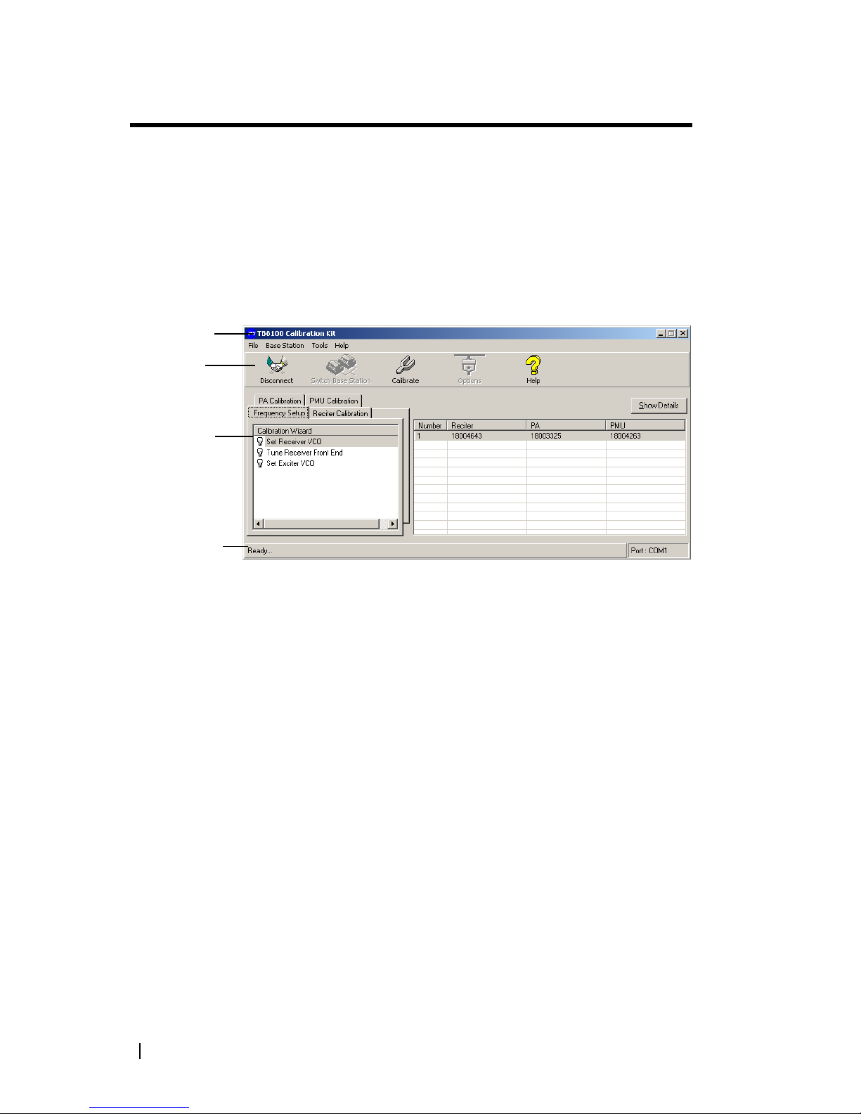
Using the TB8100 Calibration Kit
When you start the TB8100 Calibration Kit, the main program window
appears.
The main program window has four tabs. The Calibration Wizards displayed
on each tab are only visible once you are connected to the reciter or the base
station.
When the TB8100 Calibration Kit is connected to the reciter or base station,
you can view further details (such as module number, type, serial number, band,
and hardware version) about the currently selected module by clicking Show
Details.
Frequency Setup
tab
Shows the three Calibration Wizards that take you step-by-step through the
frequency setup.
Reciter Calibration
tab
Shows the seven calibration procedures that you can perform on the reciter.
The Calibration Wizard takes you step-by-step through the procedure you
have selected.
PA Calibration tab Shows the four calibration procedures that you can perform on the power
amplifier. The Calibration Wizard takes you step-by-step through the
procedure you have selected.
PMU Calibration
tab
Shows the procedure that you can perform on the PMU.
Menu bar
Toolbar
Calibration
Wizards
Status bar
Page 7
TB8100 Calibration Kit User’s Manual Using the TB8100 Calibration Kit 2
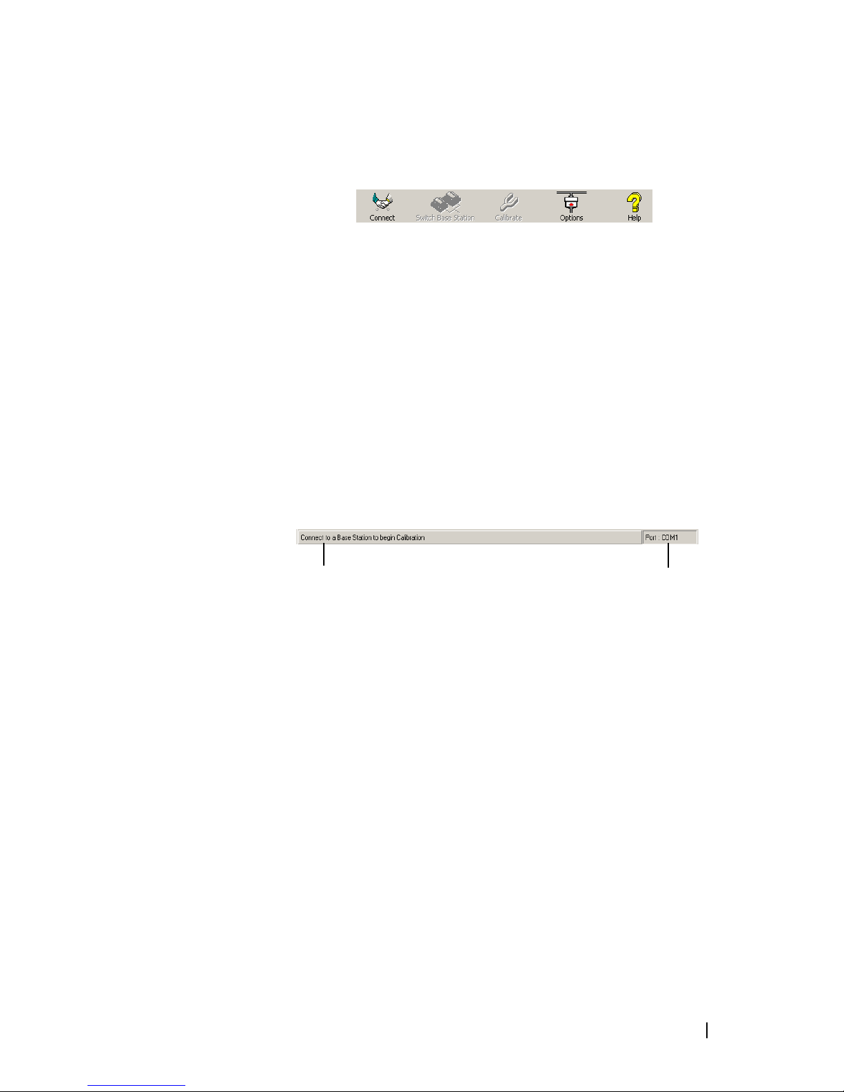
About the Toolbar
The toolbar gives you quick access to commonly used menu commands. For
example, instead of selecting Base Station > Calibrate, you can click the
Calibrate icon on the toolbar.
Connect Connects the TB8100 Calibration Kit to the base station and opens the
communication channels.
Switch Base
Station
Lets you select another base station to calibrate if there are multiple base stations
in the rack (not currently supported).
Calibrate Runs the Calibration Wizard for the currently selected task.
Options Allows you to set the COM port and default calibration mode.
Help Opens the online help for the window you are currently in.
About the Status Bar
The status bar provides you with useful information that supplements the
display in the main window.
Miscellaneous messages
COM port in use
Page 8

3 Equipment Required © Tait Electronics Limited April 2006
Equipment Required
You need the following equipment for field calibration:
■ Calibration and Test Unit (CTU, order code TBA0STU), which comes
complete with the cables you will need for connection to the reciter/PA and
the PC. For more information about the CTU, please refer to TN-778 The
Calibration and Test Unit.
■ Tool kit (order code TBA0ST2) which comprises tuning tools and the
required screwdrivers in a tool pouch. The ceramic-tipped Murata tuning
tool is used for most procedures, but the metal-tipped Johanson 8777 tuning
tool with its narrower blade is needed for tuning the front end of H-band
and K-band receivers.
■ 10-30 V DC power supply (if the PMU does not have a 12 V or 24 V
auxiliary power supply module)
■ RS-232 cable
■ RF attenuator (optional – depends on the setup)
You may need the following additional equipment for a service center
calibration:
■ Frequency counter
■ Modulation meter
■ RF signal source
■ AC millivoltmeter (one with a differential input may be required for
“Calibrating the Balanced Lines” on page 20)
Refer to the individual procedures for equipment setup diagrams.
Calibration Overview
Any calibration process creates digital values and a calibration date, which are
stored in the base station. The Service Kit can display the date of the last
calibration. Many calibration procedures initially clear the stored digital values.
If you do not complete the procedure or the stored digital values are outside
acceptable limits, the module is left uncalibrated. An uncalibrated reciter will go
into Download mode on startup and cannot be put into Run mode. An
uncalibrated PA generates a calibration invalid alarm.
If the procedure you are performing requires access to tuning holes, you need
to remove the reciter from the subrack and connect to it via the CTU.
The following tables summarise, for each procedure, whether or not you need
to remove the reciter from the subrack, and what equipment (in addition to a
PC with the TB8100 Calibration Kit software) you will need.
Page 9
TB8100 Calibration Kit User’s Manual Calibration Overview 4
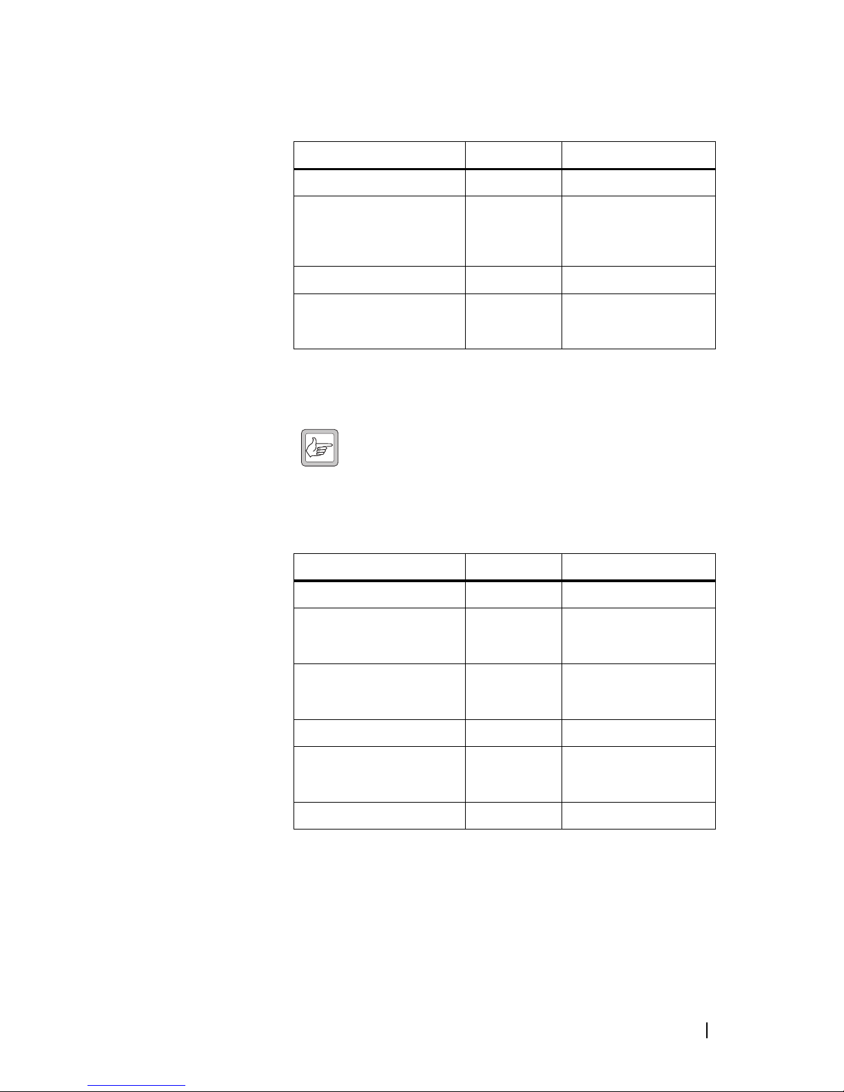
Field Calibration
The following procedures can be carried out in the field.
Service Center Calibration
The following additional procedures may need to be carried out after a module
has been serviced.
Note: Replacing or repairing a board module may mean that the
module’s product code, product type (frequency band), serial
number, and/or hardware version need to be re-entered or altered.
To do this, your Calibration Kit needs a dongle. The Service Manual indicates
when a module detail needs re-entering or altering.
Reciter
Procedure Connection Equipment Required
Adjusting receiver lock band Outside subrack Murata tuning tool, CTU
Tuning the receiver Outside subrack Murata tuning tool,
Johanson tuning tool (for Hband and K-band reciters),
CTU
Adjusting exciter lock band Outside subrack Murata tuning tool, CTU
Adjusting the carrier frequency
offset
Depends on
reciter
Murata tuning tool,
Frequency counter, RF
attenuator (only if using PA)
Procedure Connection Equipment Required
Automatically tuning FCL Inside subrack None
Calibrating the FCL modulation Outside subrack Murata tuning tool, CTU,
modulation meter, RF
attenuator (only if using PA)
Calibrating the VCO modulation Outside subrack Murata tuning tool, CTU,
modulation meter, RF
attenuator (only if using PA)
Calibrating the RSSI Inside subrack RF signal source
Calibrating the balanced lines Inside subrack CTU, AC millivoltmeter
(perhaps with differential
input)
Calibrating the unbalanced lines Inside subrack CTU, AC millivoltmeter
Page 10
5 Selecting the Communications Port © Tait Electronics Limited April 2006
Power Amplifier
Power
Management Unit
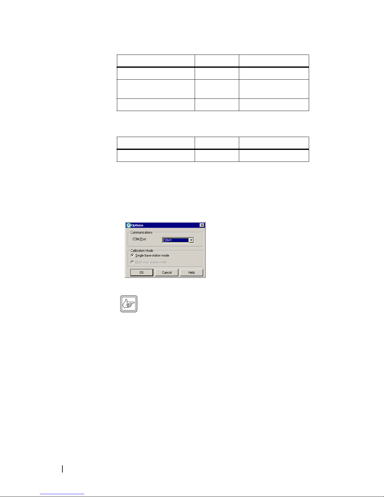
Selecting the Communications Port
Before you connect to a base station, you should first define the
communications (COM) port that you want to use.
To select the COM port
1. Select Tools > Options.
2. Select the port that you want to use from the COM Port list.
Note: The available COM ports are detected by the program and
appear in the list.
3. Click OK.
The COM port you selected is now shown on the status bar.
Connecting to a Reciter Outside the Subrack
Field calibration procedures require access to the tuning holes, so you need to
remove the reciter from the subrack and connect to it using a CTU.
Equipment ■ Calibration and test unit (CTU)
■ An IBM compatible PC
■ 10-30 V DC power supply
■ 16-way cable
■ RS-232 cable
Procedure Connection Equipment Required
Calibrating the PA bias Inside subrack None required
Calibrating the forward &
reverse detector bias voltages
Inside subrack None required
Calibrating the PA power Inside subrack None required
Procedure Connection Equipment Required
Output voltage calibration Inside subrack Digital multimeter
Page 11
TB8100 Calibration Kit User’s Manual Connecting to a Reciter Outside the Subrack 6
Setup
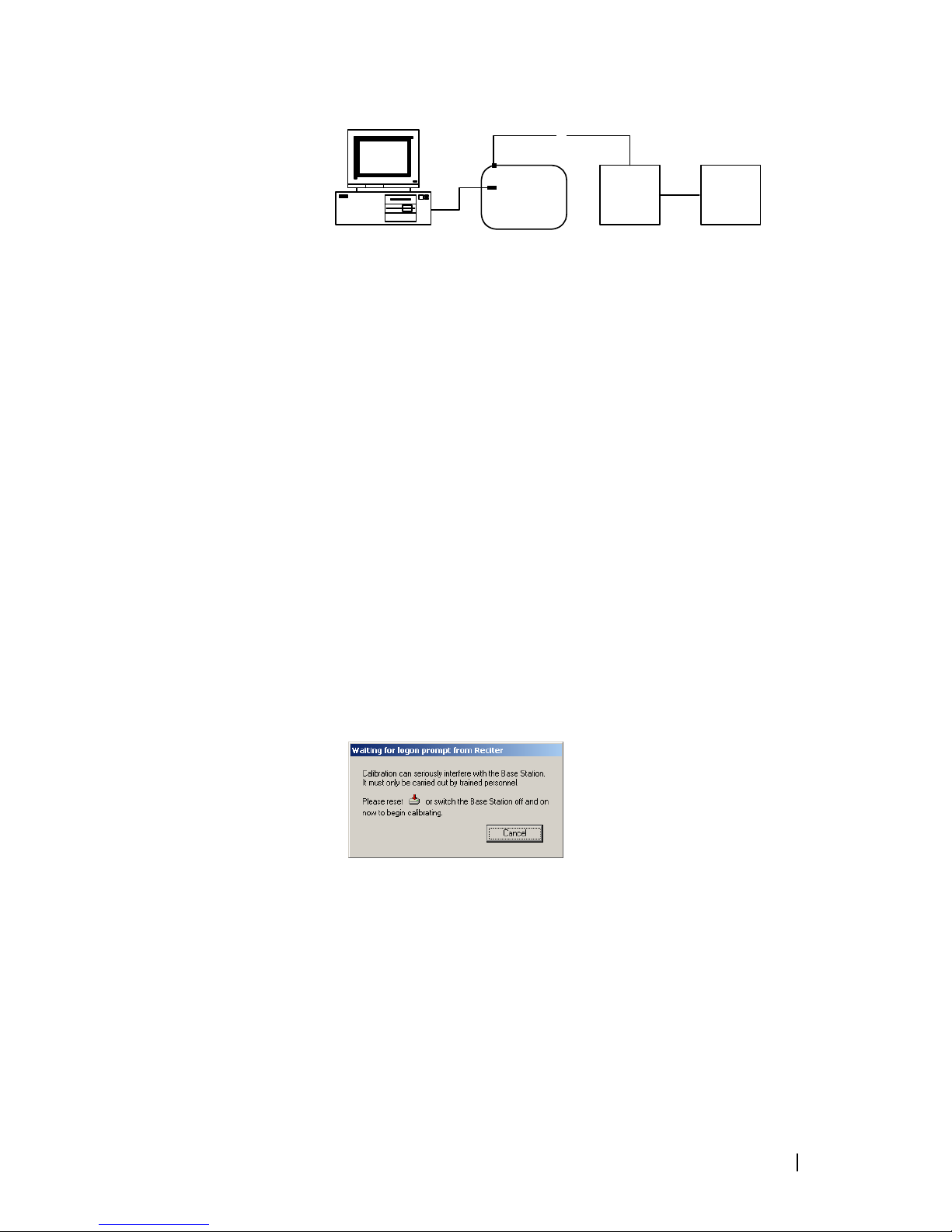
To connect to the reciter
1. Remove the reciter from the subrack (for instructions, see the Installation
and Operation Manual).
2. Set up the equipment as follows.
■ Connect the reciter to the calibration and test unit (CTU) using the 16-
way cable.
■ Connect your computer to the CTU by plugging the RS-232 cable into
the programming port.
■ Using the power cable supplied in the calibration test kit, connect the
reciter to the 10-30 V DC power supply, but do not power it up yet. If
the base station’s PMU has a 12 V or 24 V auxiliary power output, you
can use this as the power supply. A connector is supplied with the CTU.
3. Start the TB8100 Calibration Kit program, and check that the correct COM
port is selected.
4. Click Connect to start the connection process.
5. When you see the “Waiting for logon prompt from Reciter” screen, power
up the reciter. If it is already on, turn it off, and then on.
6. When the TB8100 Calibration Kit program has successfully connected to
the reciter, the Calibration Wizards are displayed in the main window.
You are now ready to tune and calibrate the reciter.
3
6
4
5
2
1
7
8
1 PC 5 16-way cable
2 RS-232 cable 6 Reciter
3 CTU 7 Power cable
4 Programming port 8 10-30 V DC power supply
Page 12
7 Connecting to a Reciter via the Control Panel © Tait Electronics Limited April 2006
Connecting to a Reciter via the Control Panel
For calibration procedures that do not require access to tuning holes, you can
leave the reciter in the subrack and connect your PC to the control panel as
follows.
Equipment ■ An IBM compatible PC
■ RS-232 cable
Setup
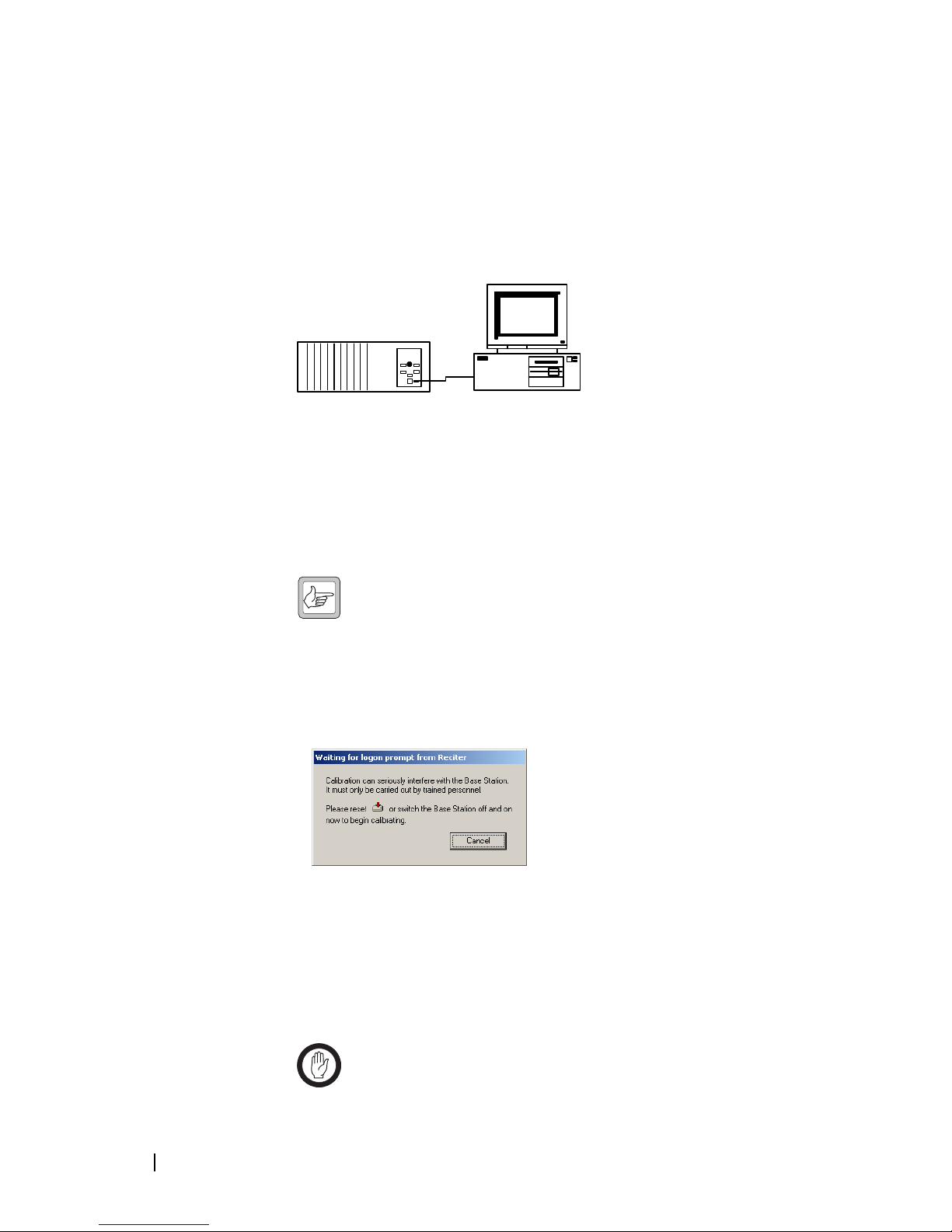
To connect to a reciter in the subrack
1. Connect your computer to the base station by plugging the RS-232 cable
into the serial port of the base station’s control panel.
Note: If the base station is fitted with a TaitNet RS232 system
interface, the control panel serial port is disabled; connect to the
serial port at the reciter rear instead.
2. Start the TB8100 Calibration Kit program, and check that the correct COM
port is selected.
3. Click Connect to start the connection process.
4. As soon as you see the “Waiting for logon prompt from Reciter” screen,
power up the base station. If it is already on, turn it off, and then on.
5. When the TB8100 Calibration Kit program has successfully connected to
the base station, the Calibration Wizards are displayed in the main window.
You are now ready to carry out calibration procedures.
Disconnecting from the Base Station/Reciter
Once calibration is completed, click Disconnect before exiting the Calibration
Kit.
Important: Disconnecting when a calibration process is not
completed may leave the base station in an uncalibrated state.
4
1
3
2
1 Base station 3 RS-232 cable
2 Serial port 4 PC
Page 13

TB8100 Calibration Kit User’s Manual Troubleshooting 8
Troubleshooting
Application Errors All application errors are recorded in a log file called “CalError.log”. The data,
time, location, and any other useful information is stored in this file, which may
be helpful when troubleshooting.
The file is saved in the Logfiles subfolder of the application folder and stores up
to 1000 of the most recent logged items.
Verifying the
Software Version
If you need to verify the version of the TB8100 Calibration Kit, select
Help > About.
Commands
Record
All the commands sent and received by TB8100 Calibration Kit are saved in a
file called “CCTM.log”. The date, time, command number, and parameters are
all stored in this file, which may be helpful when troubleshooting.
The file is also saved in the Logfiles subfolder and stores up to 1000 of the most
recent logged items.
Page 14

9 Adjusting the Receiver Lock Band © Tait Electronics Limited April 2006
Adjusting the Frequency Setup
Before the TB8100 base station is installed, connected, and configured, you
must prepare it for operation by adjusting the switching range of the receiver,
optimising the receiver response across the switching range, and adjusting the
exciter lock band or selecting an exciter sub-band.
Note: If the required switching range for the base station has already
been defined, you don’t need to perform these procedures.
Tip: Use the TB8100 Service Kit to monitor the base station and
find out its current switching range.
Important: Be careful when using the tuning tools. Applying too
much pressure or attempting to turn the tool beyond the end of the
range can crack the tuning slug. Unscrewing a slug too far can
remove it completely.
Adjusting the Receiver Lock Band
The first step in preparing the TB8100 base station for operation is to adjust the
receiver lock band (switching range). The lock band is the range of frequencies
that the receiver is calibrated to operate on.
Equipment ■ Murata tuning tool
■ CTU
To adjust the receiver lock band
1. Remove the reciter from the subrack. (For instructions, see the Installation
and Operation Manual.)
2. Connect the Calibration Kit to the reciter (see “Connecting to a Reciter
Outside the Subrack” on page 5).
3. Select the Frequency Setup tab, and double-click Set Receiver VCO. The
Set Receiver VCO Wizard appears. The display varies, depending on the
reciter band.
4. Enter the Center Frequency (which must be a multiple of 500 kHz) of the
lock band that you want to use, and click Next.
5. Insert the Murata tuning tool into the correct receiver VCO tuning hole for
the reciter type (see below) and then click Next.
6. Adjust the receiver VCO trimmer until the actual band matches the desired
band. The bands turn green.
7. Click Finish. This stores the lock band in the reciter.
The icon on the Frequency Setup tab indicates that this task is complete. Proceed to tune the front end.
Page 15

TB8100 Calibration Kit User’s Manual Tuning a UHF Receiver Front End 10
Tuning a UHF Receiver Front End
The second step in tuning the reciter frequency is to tune the receiver front
end, by adjusting the helical filters. Tuning aims to maximise the receiver’s
sensitivity and to optimise its response across the lock band (switching range).
To help you do this, there is a graph of the RSSI readings in step two of the
Tune Receiver Front End Wizard. A number of RSSI readings are measured
across the switching range. These readings are then continually averaged to
produce the graph.
Important: After tuning the reciter front end, you must re-calibrate
the RSSI. This requires a signal generator.
Otherwise the value
reported by the Service Kit will be in error and RSSI gating levels
will be incorrect.
You should aim to achieve a response that looks something like this:
Equipment ■ Johanson tuning tool
■ CTU
Receiver VCO tuning hole for
H band (400 - 520 MHz) and
K band (792 - 824 MHz)
Receiver VCO tuning hole for
B band (136-174 MHz) and
C band (174 - 225 MHz)
Page 16

11 Tuning a UHF Receiver Front End © Tait Electronics Limited April 2006
Setup
To tune the front end of a UHF (H-band or K-band) receiver, follow
these steps.
1. Ensure you are already connected to the reciter (see “Connecting to a
Reciter Outside the Subrack” on page 5).
2. Select the Frequency Setup tab, and double-click Tune Receiver Front
End. The Tune Receiver Front End Wizard appears.
Note: If you haven’t adjusted the receiver lock band in the current
session, an alert appears, recommending that you run the Set
Receiver VCO wizard first. If the lock band needs adjusting, click
Yes and carry out that procedure first. If you are confident that the lock band
is correct, click No.
3. Connect the CTU’s noise source to the receiver input, turn the noise source
on, and then click Next.
4. Click Coarse (fast) and use the tuning tool to roughly adjust the front-end
helical filters on the receiver. As you do so, observe the graphical RSSI
readings across the lock band. Adjust to maximize the response across the
entire switching band.
Note: As the response gets flatter, you may find it helpful to select a
more sensitive scale, so that you can see the graphical reading in
more detail.
Use the tuning tools as follows.
6
4
3
1
2
5
1 PC 2 RS-232 cable 3 Programming port
4 CTU 5 Noise source 6 Reciter
First set
Second set
Helical
filters:
Page 17

TB8100 Calibration Kit User’s Manual Tuning a VHF Receiver Front End 12
a. Insert the Johanson tuning tool into the first hole of the first (horizontal)
set. You can start with the hole on the left side and proceed along to the
hole on the right, or vice versa. On K-band reciters, the third hole tends
to tune with the slug well out of the filter body. Be careful not to
unscrew the slug completely.
b. Tune each of the resonators in the first set once to give the best response.
c. Insert the Johanson tuning tool into the first hole of the second (vertical)
set. You can start with the top hole and proceed down to the bottom
hole, or vice versa. (For hardware version 4.00 or earlier H-band reciters,
use the Murata tuning tool on this set instead, as instructed by the wiz-
ard.)
d. Tune each of the resonators in the second set once to give the best
response.
e. Repeat this procedure as necessary to refine the response.
5. Once you have roughly tuned the front-end helical filters, click Fine
(slow). Repeat the above procedure to fine tune the front-end helical filters
until the response is peaked in the middle of the lock band and not more
than -1 dB at the ends of the band.
Note: When using the Fine (slow) setting, you may notice a slight
delay as the reading from tuning the front-end helical filters takes
approximately one second to appear on the graph.
6. Click Finish. An alert appears, asking that you calibrate the RSSI. The icon
on the Frequency Setup tab indicates that this task is complete.
7. Re-calibrate the RSSI (see “Calibrating the RSSI” on page 19).
Tuning a VHF Receiver Front End
The second step in tuning a VHF reciter is to tune the receiver front end, by
adjusting trimmer capacitors. Tuning aims to maximise the receiver’s sensitivity
and to optimise its response across the lock band (switching range).
To help you do this, there is a graph of the RSSI readings in step two of the
Tune Receiver Front End Wizard. A number of RSSI readings are measured
across the switching range. These readings are then continually averaged to
produce the graph.
After tuning the reciter front end, you must re-calibrate the RSSI. This requires
a signal generator.
Otherwise the value reported by the Service Kit will be
in error and RSSI gating levels will be incorrect.
You should aim to achieve a response that looks something like this:
Equipment ■ Tuning tool
Page 18

13 Tuning a VHF Receiver Front End © Tait Electronics Limited April 2006
■ CTU
Setup
To tune a VHF (B-band or C-band) receiver front end, follow these steps.
1. Ensure you are already connected to the reciter (see “Connecting to a
Reciter Outside the Subrack” on page 5).
2. Select the Frequency Setup tab, and double-click Tune Receiver Front
End. The Tune Receiver Front End Wizard appears.
Note: If you haven’t adjusted the receiver lock band in the current
session, an alert appears, recommending that you run the Set
Receiver VCO wizard first. If the lock band needs adjusting, click
Yes and carry out that procedure first. If you are confident that the lock band
is correct, click No.
3. Connect the CTU’s noise source to the receiver input, turn the noise source
on, and then click Next.
4. Click Coarse (fast) and use the Murata tuning tool to roughly adjust the
four front-end trimmers on the receiver. You can do this in any order. As
you do so, observe the graphical RSSI readings across the lock band. Adjust
to optimise the response across the entire switching band.
Note: As the response gets flatter, you may find it helpful to select a
more sensitive scale, so that you can see the graphical reading in
more detail.
5. Once you have roughly tuned the trimmers, click Fine (slow). Repeat the
above procedure until the response is flat in the middle of the lock band and
not more than -1 dB at the ends of the band.
Note: When using the Fine (slow) setting, you may notice a slight
delay as the reading from tuning the trimmers takes approximately
one second to appear on the graph.
6. Click Finish. An alert appears, asking that you calibrate the RSSI. The icon
on the Frequency Setup tab indicates that this task is complete.
7. Re-calibrate the RSSI (see “Calibrating the RSSI” on page 19).
6
4
3
1
2
5
1 PC 2 RS-232 cable 3 Programming port
4 CTU 5 Noise source 6 Reciter
Page 19

TB8100 Calibration Kit User’s Manual Adjusting the Exciter Lock Band 14
Adjusting the Exciter Lock Band
If you are preparing the base station for operation, adjusting the exciter lock
band is the third step in tuning the reciter. Alternatively, this procedure can be
performed independently of the other two calibration wizards on the
Frequency Setup tab. Adjusting the exciter lock band defines the range of
frequencies that the base station is able to transmit on.
Note: When performing this procedure, you don’t need to
terminate the exciter output port. An internal output pad means that
there is a good impedance match at this interface.
Equipment ■ Tuning tool
■ CTU
To calibrate the exciter lock band
1. Ensure you are already connected to the reciter (see “Connecting to a
Reciter Outside the Subrack” on page 5).
2. Select the Frequency Setup tab, and double-click Set Exciter VCO. The
Set Exciter VCO Wizard appears.
3. Enter the center frequency (which must be a multiple of 500 kHz) of the
lock band that you want to use, and click Next.
4. Insert the Murata tuning tool into the correct exciter VCO tuning hole (see
below) and adjust the trimmer until the actual band matches the desired
band. The bands turn green. Click Finish.
Once you have finished adjusting the exciter lock band, the icon on the
Frequency Setup tab indicates that this task is complete.
Trimmer holes for receiver
front-end tuning
(B band 136 - 174 MHz and
C band 174 - 225 MHz)
Page 20
15 Selecting the Exciter Sub-band © Tait Electronics Limited April 2006
Selecting the Exciter Sub-band
The lock band of K-band and L-band exciters does not normally need
adjusting. Instead you select a sub-band that the reciter will operate on. These
exciters have two VCOs and the one you select determines the sub-band.
Equipment ■ Murata tuning tool
■ CTU
To select the exciter sub-band
1. Ensure you are already connected to the reciter (see “Connecting to a
Reciter Outside the Subrack” on page 5).
2. Select the Frequency Setup tab, and double-click Set/Select Exciter
VCO. The Set/Select Exciter VCO Wizard appears.
3. Select one of the two available lock bands and then click Next. This
specifies the lock band that the exciter operates in.
4. If the reciter RF board has been repaired, you need to adjust the lock band.
Insert the Murata tuning tool into the correct exciter VCO tuning hole (see
below) and adjust the trimmer until the actual band matches the desired
band. The bands turn green.
5. Click Finish.
Once you have finished, the icon on the Frequency Setup tab indicates that
this task is complete.
Exciter VCO tuning hole
for H band
(400 - 520 MHz)
Exciter VCO tuning hole for
B band (136-174 MHz)
and C band (174-225 MHz)
Exciter VCO tuning hole for
K band (850-869 MHz) and
L1 band (852-854 MHz). L2 not
used.
Exciter VCO tuning hole for
K band (762-776 MHz),
L1 band (928-930 MHz), and
L2 band (927-941 MHz)
Page 21

TB8100 Calibration Kit User’s Manual Calibrating the Exciter 16
Calibrating the Reciter
The reciter is fully calibrated in the factory, but if the reciter is serviced you may
need to perform the following procedures:
■ Calibrating the Exciter
■ Calibrating the RSSI
■ Audio Calibration
To compensate for frequency drift, you may need to perform the following:
■ Carrier Frequency Offset Adjustment (Older Reciters) or
■ Carrier Frequency Offset Adjustment (Newer Reciters)
All these procedures can be done independently of each other, although it is
recommended that you tune the receiver before you calibrate the RSSI.
Important: It is recommended that only accredited service centers
and Tait engineers perform these procedures.
Calibrating the Exciter
You will need to calibrate the exciter if you have made component-level repairs
to it. There are three procedures that must all be completed in order:
1. Auto-tune the FCL
2. Calibrate the FCL
3. Calibrate the VCO
Automatically Tune the Frequency Control Loop (FCL)
Tuning the FCL calibrates the voltage levels used in the detectors for the FCL.
To automatically tune the FCL
1. Connect the Calibration Kit PC to the reciter and start the Calibration Kit.
2. Select the Reciter Calibration tab, and double-click FCL Auto Tuning.
The FCL Auto Tuning Wizard appears.
3. Click Calibrate to automatically tune the FCL.
The icon on the Reciter Calibration tab indicates that this task is complete.
You will now need to calibrate the FCL.
Calibrating the FCL
This is step two of calibrating the exciter. Once you have auto-tuned the FCL,
you should calibrate it.
Equipment ■ Tuning tool
■ CTU
■ Modulation meter
■ RF attenuator (only required if you are using a PA)
Page 22

17 Calibrating the Exciter © Tait Electronics Limited April 2006
Setup
To calibrate the FCL
1. Ensure that the Calibration Kit PC is connected to the reciter.
2. Select the Reciter Calibration tab, and double-click FCL Calibration. The
FCL Calibration Wizard appears.
3. Attach an appropriate Load and Modulation meter to the PA or exciter
output, set the meter to measure the RMS deviation, and then click Next.
(If you are using a PA, it will now transmit.)
4. Insert the Murata tuning tool into the correct exciter VCO tuning hole (see
below) and adjust the trimmer until the actual band matches the desired
band. The bands turn green. Click Next.
5. Use the slider to adjust the deviation at 1 kHz until it is 2107 Hz RMS
(3 kHz peak).
6. Select the 30 Hz Modulation Test and adjust the deviation at 30 Hz until it
is 2107 Hz
RMS (3 kHz peak).
7. Repeat steps 5 and 6 until the deviation is 2107 Hz RMS at both 1 kHz and
30 Hz.
8. Click Finish. (If you are using a PA, it will now stop transmitting.)
When you have finished calibrating the FCL, the icon on the Reciter
Calibration tab indicates that this task is complete.
You will now need to calibrate the VCO.
1 Reciter 3 RF attenuator (only required if using a PA)
2 PA (optional) 4 Modulation meter
1
2
3
4
Exciter VCO tuning hole for
K band (850-869 MHz) and
L1 band (852-854 MHz). L2 not
used.
Exciter VCO tuning hole for
K band (762-776 MHz),
L1 band (928-930 MHz), and
L2 band (927-941 MHz)
Exciter VCO tuning hole
for H band
(400 - 520 MHz)
Exciter VCO tuning hole for
B band (136-174 MHz)
and C band (174-225 MHz)
Page 23

TB8100 Calibration Kit User’s Manual Calibrating the Exciter 18
Calibrating the VCO
This is step three of calibrating the exciter.
Once you have tuned and calibrated the FCL, you calibrate the VCO at
frequencies across the whole lock band. This involves selecting a sub-band,
adjusting the lock band trimmer, and then moving on-screen sliders to adjust
the deviation to 3 kHz for each of a set of frequencies.
Equipment ■ Tuning tool
■ CTU
■ Modulation meter
■ RF attenuator (only required if you are using a PA)
Setup
To calibrate the VCO
1. Ensure that the Calibration Kit PC is connected to the reciter.
2. Select the Reciter Calibration tab, and double-click VCO Calibration.
The VCO Calibration Wizard appears.
3. Attach an appropriate Load and Modulation meter to the PA or exciter
output, set the meter to measure the peak deviation, and then click Next.
(If you are using a PA, it will now transmit.)
4. Adjust the exciter lock band trimmer until the actual band matches the
desired band. The bands turn green.
5. Click Next. Step 3 of the wizard appears.
6. Calibrate each of the frequencies shown. Follow these steps.
a. Click the option button alongside a frequency.
b. Using the Fine and Coarse arrows, adjust the slider until the deviation
shown on the modulation meter is 3000 Hz (peak).
c. Repeat steps a) and b) until all frequencies for the band are calibrated.
This enables the Next Band button.
7. Click Next Band and repeat steps 4) through 6). Repeat until all
frequencies in all bands have been calibrated.
8. If you are connected to a K-band or L1-band reciter, click Next. Select
which of the two available bands the reciter will operate on.
9. Click Finish. (If you are using a PA, it will now stop transmitting.)
When you have finished calibrating the VCO, the icon on the Reciter
Calibration tab indicates that this task is complete.
1 Reciter 3 RF attenuator (only required if using a PA)
2 PA (optional) 4 Modulation meter
1 2
3
4
Page 24

19 Calibrating the RSSI © Tait Electronics Limited April 2006
You should now adjust the exciter lock band because it was re-tuned several
times during this procedure. This means that the exciter is no longer on the
required frequency.
Calibrating the RSSI
Calibrating the RSSI (received signal strength indicator) ensures that the
reciter's internal RSSI values accurately reflect the actual received signal
strength. Changing the receiver's lock band can alter the calibration accuracy by
about 1 dB.
Note: Ensure that the receiver’s lock band has already been adjusted
to the required setting before carrying out this procedure. (See
“Adjusting the Receiver Lock Band” on page 9.)
Equipment ■ RF signal source
Setup
To calibrate the RSSI
1. Ensure that the Calibration Kit PC is connected to the reciter.
2. Select the Reciter Calibration tab, and double-click RSSI Calibration. An
alert appears, recommending that you tune the receiver. If the receiver
needs tuning, click Yes and carry out that procedure before continuing.
If you are confident that the receiver is correctly tuned, click No. The RSSI
Calibration Wizard appears.
3. Apply a signal (modulated at 1 kHz tone, 3kHz deviation peak) at the base
station’s center frequency. Use the CTU to confirm that the tone is being
output on the line, and then click Next.
4. Set the RF input signal to a level of -80 dBm, and then click Next.
5. Vary the RF level, and check that the value shown in the RSSI Gain Setting
box corresponds with the value shown on your test instrument. This is to
make sure the RSSI is correctly calibrated. Click Finish.
When you have finished calibrating the RSSI, the icon on the Reciter
Calibration tab indicates that this task is complete.
1
2
1 RF signal source
2 Reciter
Page 25

TB8100 Calibration Kit User’s Manual Audio Calibration 20
Audio Calibration
You should calibrate the audio outputs/inputs if the system interface has been
replaced or changed at all.
Note: The balanced and unbalanced lines can be calibrated
independently of each other.
Calibrating the Balanced Lines
Calibrating the balanced lines adjusts their gain, so that when you set line levels
using the TB8100 Service Kit software, the actual line level correctly reflects
the Service Kit settings. (Refer to the TB8100 Service Kit User’s Manual for
further information.)
Equipment ■ CTU
■ AC millivoltmeter
Important: If the reciter you are calibrating has either the product
code TBA4xxx-0A0x or TBA5xxx-0A0x, its balanced line output
is not transformer isolated. Ensure that the line meter you are using
has a differential input otherwise the balanced line output will not
be calibrated properly.
Setup for
Balanced Line Out
Setup for
Balanced Line In
1
6
3
4
2
5
1 Reciter 3 CTU 5 Line output
2 25-way cable 4 System interface port 6 AC millivoltmeter
1
3
7
5
4
2
6
1 Reciter 3 CTU 5 Line output
2 25-way cable 4 System interface port 6 AC millivoltmeter
7 Line input
Page 26

21 Audio Calibration © Tait Electronics Limited April 2006
To calibrate the balanced input and output lines
1. Ensure that the Calibration Kit PC is connected to the reciter.
2. Select the Reciter Calibration tab, and double-click Balanced Line
Calibration. The Balanced Line Calibration Wizard appears.
3. Attach an AC millivoltmeter and terminate the balanced output in 600
ohms (either using the load on the CTU or looping the balanced output to
the balanced input), and then click Next.
4. Adjust the slider in the dialog box until the audio level on the millivoltmeter
reads 1 V
PP (0.354 VRMS).
Note: Click Coarse to roughly adjust the audio level, and once you
get within range, click Fine for more precise control over the
settings. To move up or down 10 mV
PP, click either side of the
slider bar.
5. Click Next. The balanced output is now calibrated.
6. Note the level of the AC millivoltmeter, and then turn off the 600 ohm
load.
7. Connect the balanced output to the balanced input. Verify that the
millivoltmeter reading is substantially unchanged. (This confirms that the
input provides a 600 ohm impedance.)
8. Click Finish. The balanced input is now calibrated.
When you have finished calibrating the balanced lines, the icon on the
Reciter Calibration tab indicates that this task is complete.
Calibrating the Unbalanced Lines
Calibrating the unbalanced lines adjusts their gain, so that when you set line
levels using the TB8100 Service Kit software, the actual line level correctly
reflects the Service Kit settings. (Refer to the TB8100 Service Kit User’s Manual
for further information.)
Equipment ■ CTU
■ AC millivoltmeter
Setup for
Unbalanced Line
Out
1
6
3
4
2
5
1 Reciter 3 CTU 5 Unbalanced line output
2 25-way cable 4 System interface port 6 AC millivoltmeter
Page 27

TB8100 Calibration Kit User’s Manual Audio Calibration 22
Setup for
Unbalanced Line
In
To calibrate the unbalanced input and output lines
1. Ensure that the Calibration Kit PC is connected to the reciter.
2. Select the Reciter Calibration tab, and double-click Unbalanced Line
Calibration. The Unbalanced Line Calibration Wizard appears.
3. Attach an AC millivoltmeter to the unbalanced line output, and then click
Next.
4. Adjust the slider in the dialog box until the audio level on the millivoltmeter
reads 1 V
PP (0.354 VRMS) to calibrate the unbalanced line output, and then
click Next.
Note: Click Coarse to roughly adjust the audio level, and once you
get within range, click Fine for more precise control over the
settings. To move up or down 10 mV
PP, click either side of the
slider bar.
The unbalanced line output is now calibrated.
5. Connect the unbalanced output to the unbalanced input, and then click
Finish.
The unbalanced line input is now calibrated.
When you have finished calibrating the unbalanced lines, the icon on the
Reciter Calibration tab indicates that this task is complete.
1
3
5
6
4
2
1 Reciter 3 CTU 5 Unbalanced line input
2 25-way cable 4 System interface port 6 Unbalanced line output
Page 28

23 Carrier Frequency Offset Adjustment (Older Reciters) © Tait Electronics Limited April 2006
Carrier Frequency Offset Adjustment
(Older Reciters)
The carrier frequency is derived from a reference frequency generated by the
reciter’s TCXO (temperature compensated crystal oscillator). The reference
frequency can drift over time, causing an offset to the carrier frequency. When
you connect to a reciter with hardware version 00.02 or earlier, the Calibration
Kit provides the following procedure that enables you to adjust the carrier
frequency and remove the offset.
Reciters are delivered from the factory with a 0 offset. Carry out the following
procedure if you suspect that the base station is transmitting off-frequency.
(Off-frequency is defined as being outside the range of -1 to +1 ppm.) It is a
good idea to calibrate the TCXO every few years. Exactly how often you do
this will depend on the harshness of the conditions in which the base station is
operating.
Ideally, you should calibrate the TCXO at a room temperature of 25 +/- 5
degrees Celsius. Complete the calibration as quickly as possible since extended
transmission times increase temperature, which makes the calibration less
accurate.
Important: Do not carry out this procedure on reciters that are
intended for use in a quasi-synchronous system.
Equipment ■ Frequency counter
■ RF attenuator (only required if you are using a PA)
Important: The accuracy of the calibrated TCXO frequency is only
as good as the accuracy of the frequency counter.
Setup
To adjust the carrier frequency
1. Ensure that the Calibration Kit PC is connected to the reciter (see
“Connecting to a Reciter via the Control Panel” on page 7).
2. Select the Reciter Calibration tab, and double-click Carrier Freq Offset
Adjustment. The Carrier Freq Offset Adjustment Wizard appears.
3. Attach an appropriate load and frequency counter (or a test set) to the exciter
or PA output, and then click Next. (This instructs the setup to transmit.)
4. Using the slider, adjust the TCXO pot until the actual frequency is exactly
the same as the selected frequency value. Click Coarse to roughly (and
quickly) adjust the output frequency, and then click Fine to fine-tune it.
When you have finished, click Finish. (The setup now stops transmitting.)
When you have finished, the icon on the Reciter Calibration tab indicates
that this task is complete.
1
2
3
4
1 Reciter 3 RF Attenuator pad (optional)
2 PA (optional) 4 Frequency counter
Page 29

TB8100 Calibration Kit User’s Manual Carrier Frequency Offset Adjustment (Newer Reciters) 24
Carrier Frequency Offset Adjustment
(Newer Reciters)
The TCXO (temperature compensated crystal oscillator) provides a reference
frequency from which all other RF frequencies are derived. Reciters with
hardware version 00.03 and above have a voltage-controlled TCXO, with a pot
for adjusting the reference frequency to remove any carrier frequency offset.
The Carrier Freq Offset Adjustment wizard provides assistance with this
procedure.
Tait recommends that the reciter TCXO is recalibrated after 3 months service
and that annual checks are made thereafter in order to compensate for
frequency drift. Recalibration ensures that the SDB (signal displacement
bandwidth) is within 250 Hz.
The TCXO has a frequency stability of 0.5 ppm (parts per million)
corresponding to 250Hz at a carrier frequency of 500MHz. Tait recommends
that the TCXO is calibrated to within 0.1ppm.
Equipment ■ Torx 10 screwdriver (to remove the reciter cover)
■ Tuning tool
■ Frequency counter
■ RF attenuator (only required if you are using a PA)
Important: The accuracy of the calibrated TCXO frequency is only
as good as the accuracy of the frequency counter.
Setup
You need direct access to the TCXO circuitry on the reciter RF board. This
involves removing the reciter RF cover.
Important: The reciter contains devices that are susceptible to
damage from static charges. You must handle these devices
according to the recommended ESD precautions.
To adjust the carrier frequency
1. Remove the reciter from the subrack.
2. Remove the M3 Torx screws securing the reciter RF cover to the heatsink
and to the front and rear panels. (The RF side of the reciter can be identified
by the two BNC connectors on that side of the reciter’s rear.) Lift off the
RF cover.
3. Connect the Calibration Kit to the reciter (see “Connecting to a Reciter
Outside the Subrack” on page 5).
4. Select the Reciter Calibration tab, and double-click Carrier Freq Offset
Adjustment. The Carrier Freq Offset Adjustment wizard appears.
1
2
3
4
1 Reciter 3 RF Attenuator pad (optional)
2 PA (optional) 4 Frequency counter
Page 30

25 Carrier Frequency Offset Adjustment (Newer Reciters) © Tait Electronics Limited April 2006
5. Attach an appropriate load and frequency counter (or a test set) to the exciter
or PA output, and then click Next.
The exciter now begins transmitting on the center frequency of its lock
band. The Wizard displays a message similar to the following:
“Adjust RV1400 to set frequency within 0.1ppm or 48Hz of 485 MHz”
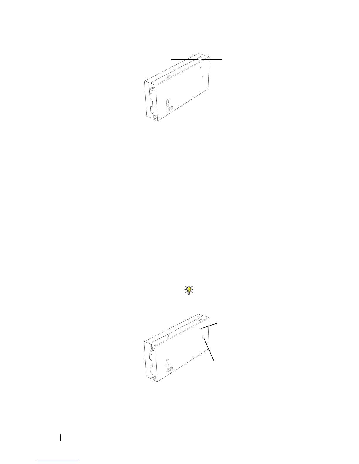
6. Use the tuning tool to adjust the TCXO tuning control (RV1400) so that
the reciter is transmitting exactly on frequency.
The following shows where the tuning control is located on B-band, Cband, and H-band reciters:
The following shows where the tuning control is located on K-band and-L
band reciters:
Page 31

TB8100 Calibration Kit User’s Manual Carrier Frequency Offset Adjustment (Newer Reciters) 26
7. Click Finish. Transmission ceases and the icon on the Reciter
Calibration tab indicates that this task is complete.
8. Replace the reciter RF cover, as follows.
a. Slide the cover into place over the front and rear panels. Make sure the
holes in the cover line up with the threaded holes in the heatsink and
front and rear panels.
b. Press the cover firmly into place and screw in the M3 Torx screws, first
on the flat face, then on the edge face.
Important: Excessively tightening the screws can damage the thread
of the aluminium heatsink. Tait recommends that you use a T10
torque driver set to 0.5 Newton meters (4.5 foot pounds).
Page 32

27 Calibrating the PA Bias © Tait Electronics Limited April 2006
Calibrating the Power Amplifier
The PA is fully calibrated in the factory, but if the PA is serviced you may need
to perform the following procedures:
■ Calibrating the PA Bias
■ Calibrating the Forward and Reverse Detector Bias Voltages
■ Calibrating the PA Power
Perform the procedures in the above order.
Important: It is recommended that only accredited service centers
and Tait engineers perform these procedures.
Calibrating the PA Bias
The driver and final transistors of the power amplifier must be biased at a
constant current. Since the characteristics of individual transistors vary slightly,
the bias current is calibrated for each device.
If either the driver or final transistor, or the PCB modules themselves, are
replaced during servicing, you should perform this procedure to calibrate the
bias current for the new device.
The bias current required for each amplifier stage is stored within the PA.
During the calibration process, the microprocessor adjusts the gate bias voltage
to obtain the required bias current for each stage.
The stage bias calibration sets up the amplifier’s DC operating conditions.
These DC conditions will be upset if there is RF present during calibration. It
is important to disconnect the RF cable from the PA input to avoid this.
The other conditions which must be met to ensure a successful calibration are
as follows:
■ No other Calibration Wizards are running
■ The supply voltage is within the range 27-29V
■ The temperature of each stage is within the range 5-50°C
To calibrate the PA stage bias current
1. Ensure that the Calibration Kit PC is connected to the base station.
2. Select the PA Calibration tab, and double-click Calibrate PA Bias.
3. Ensure that the exciter RF is isolated from the PA by disconnecting the
SMA connector on the PA front panel.
4. Click Calibrate to calibrate the PA bias.
When you have finished calibrating the power amplifier bias, the icon on
the PA Calibration tab indicates that this task is complete.
Calibrating the Forward and Reverse Detector Bias Voltages
The RF detectors, used for measuring the forward and reverse power, operate
with a small bias current. The resulting bias voltage from each detector (with
no RF present) is read and stored inside the PA. These voltages are used when
calculating the Antenna VSWR (Voltage Standing Wave Ratio).
You should calibrate the forward and reverse detector bias voltages:
Page 33

TB8100 Calibration Kit User’s Manual Calibrating the PA Power 28
■ If the Low Pass Filter (LPF)/directional coupler PCB module is replaced
■ After servicing of any components in the detector circuitry (such as the
detector diodes) on the LPF/ directional coupler PCB
To calibrate the forward and reverse detector bias voltages
1. Ensure that the Calibration Kit PC is connected to the base station.
2. Select the PA Calibration tab, and double-click Calibrate Fwd/Rev
Detector Bias Voltages.
3. Ensure that the PA is not transmitting and that there is no RF source present
at the PA RF input or output by disconnecting the input SMA connector
on the PA front panel and the ‘N’ type output connector from the rear of
the PA. Click Calibrate.
When you have finished, the icon on the PA Calibration tab indicates that
this task is complete.
Calibrating the PA Power
The power amplifier (PA) receives the RF signal from the reciter and amplifies
it to the required level, in watts, as requested by the reciter. The desired output
power is determined by the reference voltage for the power control loop.
The PA power control loop is calibrated at a single frequency, generally in the
center of the operating band.
You perform the calibration procedure to define – for each power level – the
reference DAC (Digital-to-Analogue Converter) value and forward detector
voltage.
You should only need to re-calibrate the PA power if:
■ The Low Pass Filter (LPF)/directional coupler PCB module is replaced
■ Any repairs are carried out on the forward and reverse detector circuitry on
the Low Pass Filter/directional coupler PCB module
■ You require a more accurate power calibration on a specific frequency
Equipment
■ Either an inline power meter and 50 ohm load with a high power rating, or
■ A terminating power meter and appropriate 50 ohm attenuator with a high
power rating
Setup for Inline
Power Meter
Note: Cables and connectors can easily cause a power loss of several
watts if either too long or poorly terminated. Always use the
shortest possible leads (or connectors instead of leads) between the
PA and power meter set-up.
1 3
2
4
5
1 Reciter 3
PA
5 Load
2 16-way cable 4 RF Power Meter
Page 34

29 Calibrating the PA Power © Tait Electronics Limited April 2006
To calibrate the PA transmit power
1. Ensure that the Calibration Kit PC is connected to the base station.
2. Select the PA Calibration tab, and select Calibrate PA Power.
3. Ensure that the power meter and a 50 ohm load (VSWR < 1.2:1) with a
high power rating are connected to the power amplifier RF output, and
then click Next.
4. Check that the PA RF input is connected to the reciter RF output, and that
the PA and the reciter are connected by a control bus, and then click Next.
5. For each power level shown, use the slider to adjust the DAC setting to get
the required power output, and then click Next Power to move to the next
line.
Note: Click Coarse to roughly adjust the DAC setting, and once
you get within range, click Fine for more precise control over the
settings. To move up or down one DAC value, click either side of
the slider bar.
Note: You must perform the calibration in sequence from the lowest
to the highest step. The DAC setting must be greater than the
previous one otherwise the value will not be stored in the PA, and
you cannot move to the next line.
6. When you have completed adjusting the DAC settings, click Finish.
When you have finished, the icon on the PA Calibration tab indicates that
this task is complete.
Troubleshooting Tips
DAC Settings When you adjust the DAC settings, the values for the DAC Setting, Coupler
Fwd Voltage, and Control Voltage should always increase as the power level
increases. If these values do not increase, there is either a fault with the PA or
the previous step was not calibrated correctly. If you make a mistake in the
calibration table, you must start again from step 1.
Control Voltage The Control Voltage is shown in the table to indicate the operation point
within the power control loop. The range of the control voltage is from 0 V to
7.5 V. If the control voltage reaches its limit before achieving maximum power
in the table, this indicates either a faulty gain stage in the PA or low RF input
power to the PA.
VSWR The VSWR (Voltage Standing Wave Ratio) is monitored at the RF output of
the PA during calibration. The software will not allow calibration into a load
VSWR > 1.3:1. If a calibration step cannot be stored, check that the load
VSWR is <1.3:1. It is recommended that the load should have an input
VSWR <1.2:1.
Page 35

TB8100 Calibration Kit User’s Manual Calibrating the PMU Output Voltage 30
Calibrating the Power Management Unit
There is only one calibration procedure for the PMU: calibrating its output
voltage.
Calibrating the PMU Output Voltage
Calibrating the PMU output voltage adjusts the voltage to be 28.00 V. This
procedure is only carried out when a replacement control card or
microprocessor is fitted to the PMU. Normally, the output voltage will be
accurate without calibration.
Note: Re-calibrating the PMU output voltage may result in it failing
to meet the published specification of +/- 0.5% accuracy. This is
because control cards are calibrated in the factory under half-load,
giving a voltage that is closer to 28.00 V under varying loads.
To calibrate the output voltage
1. Connect the Calibration Kit to the base station (see “Connecting to a
Reciter via the Control Panel” on page 7).
2. Select the PMU Calibration tab.
3. Double-click Output Voltage Calibration. The Calibrate Output
Voltage wizard appears.
4. Connect a digital multimeter to the PMU output and read the output
voltage.
5. Enter the voltage into the PMU Voltage box and click Calibrate.
6. When the wizard indicates that the calibration completed successfully, click
Finish.
Page 36

31 Calibrating the PMU Output Voltage © Tait Electronics Limited April 2006
Page 37

TB8100 Calibration Kit User’s Manual Tait General Software Licence Agreement 32
Tait General Software Licence Agreement
This legal document is an Agreement between you (the
“Licensee”) and Tait Electronics Limited (“Tait”). By using any
of the Software or Firmware items prior-installed in the related
Tait product, included on CD or downloaded from the Tait
website, (hereinafter referred to as “the Software or Firmware”)
you agree to be bound by the terms of this Agreement. If you do
not agree to the terms of this Agreement, do not install and use
any of the Software or Firmware. If you install and use any of the
So ft war e o r Fi r mwa re t ha t w ill b e d ee med to be accept an ce of t he
terms of this licence agreement.
The terms of this Agreement shall apply subject only to any
express written terms of agreement to the contrary between Tait
and the Licensee.
Licence
TAIT GRANTS TO YO U AS LICENSEE THE NON-EXCLUSIVE
RIGHT TO USE THE SOFTWARE OR FIRMWARE ON A SINGLE
MACHINE PROVIDED YOU MAY ONLY:
1. COPY THE SOFTWARE OR FIRMWARE INTO ANY MACHINE
READABLE OR PR INTED FORM FOR BACKUP PURPOSES IN
SUPPORT OF YOU R USE OF THE PROGRAM ON THE SINGLE
MACHINE (CERTAIN PROGRAMS, HOWEVER, MAY INCLUDE
MECHANISMS TO LIMIT OR INHIBIT COPYING, THEY ARE
MARKED “COPY PROTECTED”), PROVIDED THE COPYRIGHT
NOTICE MUST BE REPRODUCED AND INCLUDED ON ANY SUCH
COPY OF THE SOFTWARE OR FIRMWARE;
AND / OR
2. MERGE IT INTO ANOTHER PROGRAM FOR YOUR USE ON
THE SINGLE MACHINE (ANY PORTION OF ANY SOFTWARE OR
FIRMWARE MERGED INTO ANOTHER PROGRAM WILL
CONTINUE TO BE SUBJECT TO THE TERMS AND CONDITIONS
OF THIS AGREEMENT).
THE LICENSEE MAY NOT DUPLICATE, MODIFY, REVERSE
COMPILE OR REVERSE ASSEMBLE ANY SOFTWARE OR
FIRMWARE IN WHOLE OR PART.
Important Notice
THE SOFTWARE OR FIRMWARE MAY CONTAIN OPEN SOURCE
SOFTWARE COMPONENTS (“OPEN SOURCE COMPONENTS”).
OPEN SOURCE COMPONENTS ARE EXCLUDED FROM THE
TERMS OF THIS AGREEMENT EXCEPT AS EXPRESSLY STATED IN
THIS AGREEMENT AND ARE COVERED BY THE TERMS OF THEIR
RESPECTIVE LICENCES WHICH MAY EXCLUDE OR LIMIT ANY
WARRANTY FROM OR LIABILITY OF THE DEVELOPERS AND/OR
COPYRIGHT HOLDERS OF THE OPEN SOURCE COMPONENT
FOR THE PERFORMANCE OF THOSE OPEN SOURCE
COMPONENTS. YOU AGREE TO BE BOUND BY THE TERMS AND
CONDITIONS OF EACH SUCH LICENCE. FOR MORE
INFORMATION SEE:
http://support.taitworld.com/go/opensource
Title to Software
THIS AGREEMENT DOES NOT CONSTITUTE A CONTRACT OF
SALE IN RELATION TO THE SOFTWARE OR FIRMWARE SUPPLIED
TO THE LICENSEE. NOT WITHSTANDING THE LICENSEE MAY
OWN THE MAGNETIC OR OTHER PHYSICAL MEDIA ON WHICH
THE SOFTWARE OR FIRMWARE WAS ORIGINALLY SUPPLIED, OR
HAS SUBSEQUENTLY BEEN RECORDED OR FIXED, IT IS A
FUNDAMENTAL TERM OF THIS AGREEMENT THAT AT ALL
TIMES TITLE AND OWNERSHIP OF THE SOFTWARE OR
FIRMWARE, WHETHER ON THE ORIGINAL MEDIA OR
OTHERWISE, SHALL REMAIN VES TED IN TAIT OR THIRD
PARTIES WHO HAVE GRANTED LICENCES TO TAIT.
Term and Termination
THIS LICENCE SHALL BE EFFECTIVE UNTIL TERMINATED IN
ACCORDANCE WITH THE PROVISIONS OF THIS AGREEMENT.
THE LICENSEE MAY TERMINATE THIS LICENCE AT ANY TIME BY
DESTROYING ALL COPIES OF THE SOFTWARE OR FIRMWARE
AND ASSOCIATED WRITTEN MATERIALS. THIS LICENCE WILL BE
TERMINATED AUTOMATICALLY AND WITHOUT NOTICE FROM
TAIT IN THE EVENT THAT THE LICENSEE FAILS TO COMPLY
WITH ANY TERM OR CONDITION OF THIS AGREEMENT. THE
LICENSEE AGREES TO DESTROY ALL COPIES OF THE SOFTWARE
OR FIRMWARE AND ASSOCIATED WRITTEN MATERIALS IN THE
EVENT OF SUCH TERMINATION.
Limited Warranty
THE SOFTWARE OR FIRMWARE (INCLUDING OPEN SOURCE
COMPONENTS) IS SUPPLIED BY TAIT AND ACCEPTED BY THE
LICENSEE “AS IS” WITHOUT WARRA NTY OF ANY KIND EITHER
EXPRESSED OR IMPLIED, INCLUDING BUT NOT BEING LIMITED
TO ANY IMPLIED WARRANTIES AS TO MERCHANTABILITY OR
FITNESS FOR ANY PARTICULAR PUR POSE. THE LICENSEE
ACKNOWLEDGES THAT THE SOFTWARE OR FIRMWARE
(
INCLUDING OPEN SOURCE COMPONENTS) IS USED BY IT IN
BUSINESS AND ACCORDINGLY TO THE MAXIMUM EXTENT
PERMITTED BY LAW NO TER MS OR WARRANTIES WHICH ARE
IMPLIED BY LEGISLATION SHALL APPLY TO THIS AGREEMENT.
TAIT DOES NOT WARRANT THAT THE FUNCTIONS CONTAINED
IN THE SOFTWARE OR FIRMWARE (INCLUDING OPEN SOURCE
COMPONENTS) WILL MEET THE LICENSEE’S REQUIREMENTS OR
THAT THE OPERATION OF THE SOFTWARE OR FIRMWARE
(
INCLUDING OPEN SOURCE COMPONENTS) WILL BE
UNINTERRUPTED OR ERRO R FREE.
Exclusion of Liability
IN NO CIRCUMSTANCES SHALL TAIT BE UNDER ANY LIABILITY
TO THE LICENSEE, OR ANY OTHER PERSON WHATSOEVER,
WHETHER IN TORT (INCLUDING NEGLIGENCE), CONTRACT
(
EXCEPT AS EXPRESSLY PROVIDED IN THIS AGREEMENT),
EQUITY, UNDER ANY STATUTE, OR OTHERWISE AT LAW FOR
ANY LOSSES OR DAMAGES WHETHER GENERAL, SPECIAL,
EXEMPLARY, PUNITIVE, DIRECT, INDIRECT OR
CONSEQUENTIAL ARISING OUT OF OR IN CONNECTION WITH
ANY USE OR INABILITY OF USING THE SOFTWARE OR
FIRMWARE (INCLUDING OPEN SOURCE COMPONENTS).
THE LICENSEE’S SOLE REMEDY AGAINST TAIT WILL BE LIMITED
TO BREACH OF CONTRACT AND TAIT’S SOLE AND TOTAL
LIABILITY FOR ANY SUCH CLAIM SHALL BE LIMITED AT THE
OPTION OF TAIT TO THE REPAIR OR REPLACEMENT OF THE
SOFTWARE OR FIRMWARE OR THE REFUND OF THE PURCHASE
PRICE OF THE SOFTWARE OR FIRMWARE.
General
THE LICENSEE CONFIRMS THAT IT SHALL COMPLY WITH THE
PROVISIONS OF LAW IN RELATION TO THE SOFTWARE
OR FIRMWARE.
Law and Jurisdiction
THIS AGREEMENT SHALL BE SUBJECT TO AND CONSTRUED IN
ACCORDANCE WITH NEW ZEALAND LAW AND DISPUTES
BETWEEN THE PARTIES CONCERNING THE PROVISIONS
HEREOF SHALL BE DETERMINED BY THE NEW ZEALAND
COURTS OF LAW. PROVIDED HOWEVER TAIT MAY AT ITS
ELECTION BRING PROCEEDINGS FOR BREACH OF THE TERMS
HEREOF OR FOR THE ENFORCEMENT OF ANY JUDGEMENT IN
RELAT ION TO A BREACH OF THE TERMS HEREOF IN ANY
JURISDICTION TAIT CONSIDERS FIT FOR THE PURPOSE OF
ENSURING COMPLIANCE WITH THE TERMS HEREOF OR
OBTAINING RELIEF FOR BREACH OF THE TERMS HEREOF.
No Dealings
THE LICENSEE MAY NOT SUBLICENSE, ASSIGN OR TRANSFER
THE LICENCE OR THE PROGRAM EXCEPT AS EXPRESSLY
PROVIDED IN THIS AGREEMENT. ANY ATTEMPT OTHERWISE TO
SUBLICENSE, ASSIGN OR TRANSFER ANY OF THE RIGHTS,
DUTIES OR OBLIGATIONS HEREUNDER IS VOID.
No Other Terms
THE LICENSEE ACKNOWLEDGES THAT IT HAS READ THIS
AGREEMENT, UNDERSTANDS IT AND AGREES TO BE BOUND BY
ITS TERMS AND CONDITIONS. THE LICENSEE FURTHER AGREES
THAT SUBJECT ONLY TO ANY EXPRESS WRITTEN TERMS OF
AGREEMENT TO THE CONTRARY BETWEEN TAIT AND THE
LICENSEE THIS IS THE COMPLETE AND EXCLUSIVE STATEMENT
OF THE AGREEMENT BETWEEN IT AND TAIT IN RELATION TO
THE SOFTWARE OR FIRMWARE WHICH SUPERSEDES ANY
PROPOSAL OR PRIOR AGREEMENT, ORAL OR WRITTEN AND
ANY OTHER COMMUNICATIONS BETWEEN THE LICENSEE AND
TAIT RELATING TO THE SOFTWARE OR FIRMWARE.
Page 38

33 Tait General Software Licence Agreement © Tait Electronics Limited April 2006
Page 39

TB8100 Calibration Kit User’s Manual Index 34
Index
A
AC millivoltmeter
see equipment
Antenna VSWR (Voltage Standing Wave Ra-
tio)
27
audio level
calibrating
21, 22
B
balanced input
calibrating
21
balanced output
calibrating
21
band 1
entering 4
base station
connecting to
7
disconnecting from 7
bias current
required for each power level
27
RF detectors 27
C
calibration test kit
see equipment
calibration test unit (CTU)
connecting to computer
6
connecting to reciter 6
see also equipment
calibration wizards
Balanced Line Calibration Wizard
21
Calibrate Fwd/Rev Detector Bias Voltages
Wizard
28
Calibrate PA Bias Wizard 27
Calibrate PA Power Wizard 29
Carrier Freq Offset Adjustment Wizard 23,
24
FCL Auto Tuning Wizard 16
FCL Calibration Wizard 17
RSSI Calibration Wizard 19
Set Exciter VCO Wizard 14, 15
Set Receiver VCO Wizard 9
Tune Receiver Front End Wizard 11, 13
Unbalanced Line Calibration Wizard 22
VCO Band Tuning Wizard 18
COM port 5
control voltage 29
coupler fwd voltage 29
D
DAC (Digital-to-Analogue Converter)
adjusting settings
29
detector
diodes
28
detectors
forward and reverse
27
directional coupler 28, 28
driver transistor 27
E
equipment
AC millivoltmeter
20, 21
calibration test kit 3
calibration test unit (CTU) 10, 13, 20, 21
frequency counter 23, 24
modulation meter 16, 18
power meter 28
RF attenuator 16, 18, 23, 24
RF signal source 19
Torx screwdriver 24
tuning tool 9, 10, 12, 14, 15, 16, 18, 24
exciter
adjusting lock band
14
calibrating 16, 16, 16, 18
component repairs to 16
F
FCL (Frequency Control Loop)
calibrating the modulation
16
final transistor 27
forward detector 28
calibrating bias voltage 27
frequency
calibrating
23, 24
defining center frequency 9
defining range of 14
frequency counter
see equipment
G
gate bias voltage 27
H
hardware version 1
entering 4
Page 40

35 Index © Tait Electronics Limited April 2006
L
lock band
definition
9
see exciter
see receiver
log files
application errors
8
commands received and sent 8
Low Pass Filter (LPF) 28, 28
M
modulation meter
see equipment
module number
1
O
operating range
see switching range
P
PA
calibrating bias current
27
calibrating RF detector bias voltages 27
calibrating transmit power 28
connecting to 7
details 1
faulty gain stage 29
low RF input power 29
PCB module 28, 28
peak deviation
measuring
18
PMU
calibrating output voltage
30
power supply
see equipment
product code
1
entering 4
R
receiver
adjusting lock band
9
tuning front end helical filters 10, 12
reciter
calibrating
16
connecting to 5
connecting to in subrack 7
details 1
off-frequency 23
tuning the frequency 9
Reference DAC 28
resonators
see front end helical filters
reverse detector
calibrating bias voltage
27
RF attenuator 24
see equipment
RF detectors
27
RF signal source
see equipment
RMS (root means squared)
measuring deviation of
17
RSSI (Received Signal Strength Indicator)
tuning receiver
10, 12
S
serial number 1
entering 4
status bar 2
switching range
adjusting
9
definition 9
system interface 20
T
TCXO (Temperature Compensated Crystal
Oscillator)
calibrating
23, 24
toolbar 2
troubleshooting 8
PA power calibration 29
U
unbalanced input
calibrating
22
unbalanced output
calibrating
22
V
version
of Calibration Kit software
8
VSWR 27, 29
W
wizards
see calibration wizards
 Loading...