

Page 1

NEDERLANDS 3
DEUTSCH 21
ENGLISH 39
FRANÇAIS 57
ESPAÑOL 75
ITALIANO 93
TACX SERVICE CENTRES 111
www.tacx.nl
123
Page 2

Page 3

NL
Inhoud verpakking
Controleer of de onderstaande onderdelen in de verpakking aanwezig zijn
- Basic computer
- Frame CycleForce Basic
- Wervelstroomrem
- Kabelset
- Handleiding
T1424.01
2x
T1424.02
2x
T1465.012xT1465.08
2x
T1402
1x
T1408.11
1x
T1410.021xT1410.04
2x
T1410.06
1x
T1423.15
2x
T1424.03
2x
T1461.19
2x
T1615.18
1x
T1466.01
1x
T1466.021xT1466.03
1x
T1466.04
1x
T1260.074xT1461.19
4x
T2459.03
4x
- T1466 Montagezakje aanpassingset unit
- T1615 Montagezakje trainer
- Voeten en einddoppen
Page 4

4
NL
INHOUD
1 Montage Basic
Montage trainer 5
Aansluiten Basic computer 7
2 Eenmalig instellen computer
Instellen snelheidsaanduiding 8
Instellen lichaamsgewicht 8
Instellen 24-uurs klok 8
3 Gebruik computer
MODE functies bij Km/h (of Mi/h) 9
“Resetten” functies onder de MODE toets 10
Functies onder de + en - knop 10
MODE functies bij WATT 11
MODE functies bij CAD 11
SET functie bij SLOPE (hellingsweerstand) 12
SET functie bij WATTprg (geprogr. vermogen) 12
Vermogen (Watt) = Kracht x Snelheid 13
4 Trainingsadvies
Supercompensatie 14
Voorbeelden trainingsprogramma’s 14
5 Foutmeldingen 16
6 Technische specificaties &
EU-conformiteitsverklaring 18
7 Garantiebepalingen
Procedure 19
Instructies voor retourzending 19
Service formulier 20
Symbolische aanwijzingen
Geeft een belangrijke onderwerp aan. Dus: let op!
Geeft een belangrijke tip. Goed om te weten.
Inhoud
Page 5

1 MONTAGE BASIC
De Basic Ergotrainer is opgebouwd uit het inklapbare CycleForce frame waarop je fiets
gemonteerd wordt (standaard geschikt voor race- en hybride fietsen en mountainbikes
met wieldiameter 630 t/m 690 mm) en de Basic computer.
Montage trainer
Het monteren en afstellen van de trainer is éénmalig en gaat als volgt:
1 Druk moer A in einddop B en schuif einddop in de buis van het frame (fig.1).
2 Monteer voet C met bout D aan het frame. Draai bout D zodanig vast dat de
voet nog verstelbaar is.
3 Plaats frame uitgeklapt op een stevige en vlakke ondergrond. Het frame is
in- en uit klapbaar door greep E volledig in te knijpen (fig.1).
4 Draai voet C in de juiste positie (fig.2). Draai bout D goed vast en bevestig
antisliprubber F (fig.4).
5 Monteer 2 rubber ringen G en afstelbus K aan hendel H (fig.3).
Monteer vervolgens de complete hendel aan het frame, schuif wervelstroomrem I in afstelbus K
van de hendel en draai bout J zodanig vast dat de rem nog kan bewegen (fig.4).
6 Vervang de blockage van het achterwiel van de fiets door de meegeleverde Tacx blockage X.
Dit garandeert optimale klempassing en stabiliteit. Plaats vervolgens de fiets in de trainer en stel
vleugelbout L van de trainer zo af dat snelspanklem M zonder al te veel kracht gesloten kan
worden. Forceren kan beschadigingen veroorzaken!
7 Fixeer vleugelbout L door vleugelmoer N naar binnen toe vast te draaien.
Montage Basic
5
NL
E
A
D
C
B
C
1
2
10 mm
13 mm (2x)13
mm (2x)
J
LN
X
M
E
I
K
H
F
4
H
K
G
3
Page 6

6
Montage Basic
NL
8 Met hendel H kan de rol van de wervelstroomrem in- en uitgeklapt worden tegen de
band van de fiets (fig.5 en 6). Wanneer hendel H is ingeklapt kan met afstelknop R de
druk van de rol tegen de band worden afgesteld. Let er op dat de rol stevig tegen de
fietsband wordt gedrukt zodat slippen tijdens het fietsen niet mogelijk is.
Wijziging montage voor fietsen met afwijkende wieldiameter
Voordat de complete hendel aan het frame gemonteerd wordt dienen verhoog- of verlengstrips
bevestigd te worden. Zie punt 5 van de instructies.
Wieldiameter 610 - 640 mm: bevestig verhoogstrips W met 4 bouten, moeren en ringen.(fig.7).
Wieldiameter 690 - 720 mm: bevestig verlengstrips Z (fig.8).
Advies
- Controleer voordat de CycleForce gebruikt gaat worden, of na het uitklappen van het
frame, greep E volledig is teruggeveerd. Dit om beschadigingen aan het frame te voorkomen.
- Zorg er voor dat de wervelstroomrem tijdens het monteren niet valt. Er zou onbalans
kunnen ontstaan die trillingen veroorzaakt.
- Zorg er voor dat de band goed hard is opgepompt (minimaal 6 atmosfeer).
- ATB-banden met geheel of gedeeltelijk glad bandenprofiel hebben de voorkeur. Een ruw profiel
veroorzaakt lawaai en slippen van de band.
- Rem nooit abrupt tijdens het trainen op de CycleForce. Bij het remmen op het achterwiel draait
het vliegwiel door waardoor onnodige slijtage van de achterband wordt veroorzaakt.
- Controleer regelmatig of de bouten en moeren van de trainer nog goed vast zitten.
- Testen hebben uitgewezen dat de unit bij extreme prestaties nooit oververhit kan raken. Wel
kan bij langdurig en intensief gebruik de omhulling van de wervelstroomrem behoorlijk warm
worden. Laat de unit na gebruik altijd even afkoelen voordat u deze aanraakt.
H
R
H
5 6
W
W
H
Z
Z
H
7 8
Page 7

7
Montage Basic
NL
Aansluiten Basic computer
Nadat u de fiets in de CycleForce trainer geplaatst hebt kunt u de Basic computer als volgt
aansluiten:
1 Monteer de Basic computer met behulp van de twee rubberen klembandjes P op het stuur (fig.4).
2 Sluit de computer met kabel Q aan op de wervelstroomrem. Let op dat de kabel zodanig hangt
dat deze tijdens het fietsen niet kan worden geraakt door bijvoorbeeld uw schoen of het pedaal.
3 Plaats het magneetje voor de cadans R aan de binnenkant van de linker crank (fig.5).
4 Monteer de cadanssensor S aan de onderkant van de linker liggende achtervorkschede. Zorg er
voor dat de sensor zich op hoogte van de magneet bevindt met een afstand van ongeveer 3 mm
tussen magneet en sensor. Steek de kabel van de sensor in de wervelstroomrem. Let ook hier
op dat de kabel van de sensor goed vrijloopt en niet het wiel raakt.
5 Steek de stekker in het stopcontact. Controleer de ontvangst van de cadanssensor door op uw
fiets achteruit te trappen. Op het display ziet u het woord CAD oplichten. De Basic is nu klaar
voor gebruik.
Transpiratievocht en condens kunnen de printerplaat in de computer aantasten. Gebruik de
Basic niet in vochtige ruimtes en droog het display, indien nodig, na gebruik af. Dit voorkomt
beschadigingen. Bij onjuist gebruik en/of onderhoud vervalt de garantie.
5
P
P
4
S
R
S
R
Q
Page 8

Eenmalig instellen computer
8
NL
2 EENMALIG INSTELLEN COMPUTER
Nadat u de stekker in het stopcontact heeft gestoken, licht de
display kort op ter controle. Vervolgens komt u in het gewone
programma (fig.6).
U zou meteen aan de slag kunnen, ware het niet dat u voor het
eerste gebruik eenmalig uw lichaamsgewicht moet instellen.
Standaard staat de computer ingesteld op een snelheidsaanduiding van km/u en een gewicht van 75 kg. Als snelheidsaanduiding en gewicht correct zijn, gaat u meteen door in het
gewone programma.
Instellen snelheidsaanduiding
Als de snelheidsaanduiding en/of het gewicht moeten worden
ingesteld, houdt dan gedurende 6 sec. tegelijk de SET en MODE
toets ingedrukt. Daarna laat de display SET UP zien (fig.7).
Door + of - in te drukken schakelt u over van KM/h (kilometer
per uur) naar Mi/h (Eng. mijlen per uur) en terug (fig.8). Leg uw
keus voor de snelheidsaanduiding vast door MODE in te
drukken.
Instellen lichaamsgewicht
Vervolgens krijgt u het gewicht op 75 kg. (fig.9). Door + of - in
te drukken stelt u het gewicht in met stapjes van 1 kilo (fig.10).
Om de computer tijdens het fietsen het correcte vermogen te
laten berekenen, is het belangrijk het juiste gewicht in te stellen.
De berekening voor het vermogen is immers gekoppeld aan uw
gewicht. Het gewicht is instelbaar van 40 kg t/m 120 kg.
Leg vervolgens uw gewicht vast door MODE in te drukken. Bij
een volgende keer, als de computer weer wordt aangezet, zal
de computer altijd uitgaan van het laatst vastgelegde gewicht.
Uiteraard kunt u door een nieuwe SET UP het gewicht veranderen, bijvoorbeeld als iemand anders op de Basic gaat trainen.
Instellen 24-uurs klok
Nadat u het gewicht heeft ingesteld kunt u desgewenst de
24-uurs klok instellen. Als u hiervan geen gebruik wilt maken
gaat u, door 2 keer op de MODE toets te drukken, vanzelf naar
het gewone programma. De klok komt u dan tijdens het fietsen
niet tegen.
Wilt u de 24-uurs klok wel gebruiken, dan stelt u eerst de uren
in met de +/- toets. Daarna drukt u op de MODE toets en kunt
u met de +/- toets de minuten instellen. Door nog een keer op
de MODE toets te drukken is de klok ingesteld en komt u in het
gewone programma. De klok komt u nu ook tegen als u door de
andere functies bladert. Bij het uitzetten van de computer zet u
ook de klok uit.
Heeft u de volgende keer de klok weer nodig, dan moet u die via
een nieuwe SET UP procedure instellen.
KG
9
WATT ETM
SLOPE KM/h
KM/h
MI/h
6
7
8
Page 9

Gebruik computer
9
NL
KG
10
3 GEBRUIK COMPUTER
Nadat de computer is ingesteld, kunt u gaan fietsen. Alle hierna
beschreven handelingen kunt u tijdens het fietsen op de Basic,
maar ook in stilstand, uitvoeren.
De Basic registreert drie soorten gegevens. De eerste soort
heeft betrekking op uw fietssnelheid en behandelen we hieronder. Daarna komen de andere soorten (vermogen en cadans)
aan de orde.
MODE functies bij Km/h (of Mi/h)
Onder de MODE toets zitten de algemene fietsfuncties. Door
steeds één druk op de MODE toets te geven komt u achtereenvolgens tegen: ETM, TRP, ODO, MAX, AVS (zie blokschema).
Ook de 24-uurs klok zit in dit rijtje als u die van tevoren had
ingesteld.
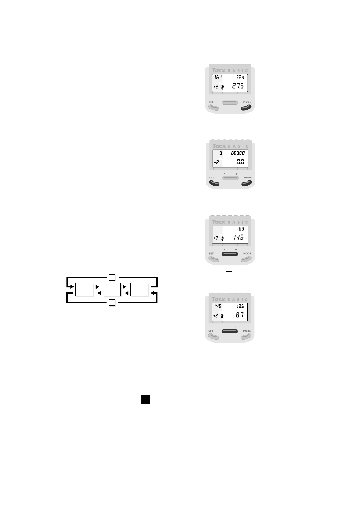
ETM (stopwatch)
U begint rechtsboven met ETM, de stopwatch (fig.11). ETM is
de tijd die wordt gefietst zonder dat de computer wordt
ge"reset" of afgezet. De stopwatch registreert uitsluitend de
gefietste tijd. U kunt dus tussendoor een pauze inlassen, zonder
dat dit de effectief gefietste tijd beïnvloedt. Zet u de computer
uit, of "reset" u de computer onder het fietsen, dan begint de
stopwatch weer bij 0.
TRP (ritafstand)
Door nog een keer op MODE te drukken verschijnt rechtsboven
TRP, de ritafstand (fig.12). De ritafstand wordt berekend zolang
de computer niet wordt ge"reset" of afgezet.
ODO (totale afstand)
Bij de volgende stap met de MODE toets verschijnt rechtsboven
ODO, de totaal afgelegde weg (fig.13). De ODO telt alle ritafstanden bij elkaar op en gaat maximaal tot 99.999 km (of mijlen)
en begint daarna weer bij 0 km.
ETM
stopwatch
TRP
ritafstand
ODO
totale
afstand
MAX
maximum
snelheid
AVS
gemiddelde
snelheid
klok
MODE
WATT TR P
SLOPE KM/h
WATT
SLOPE KM/h
WATT ODO
SLOPE KM/h
12
13
WATT ETM
SLOPE KM/h
11
Page 10

WATT MAX
SLOPE KM/h
14
Gebruik computer
10
NL
MAX (maximum snelheid)
Vervolgens verschijnt met behulp van de MODE toets rechtsboven MAX, de maximum snelheid (fig.14). Dit is de maximum
snelheid over de periode dat de computer niet wordt ge”reset”
of afgezet.
AVS (gemiddelde snelheid)
Door een laatste keer de MODE toets in te drukken verschijnt
rechtsboven AVS, de gemiddelde snelheid. De gemiddelde snelheid wordt berekend over de periode dat de computer niet
wordt ge”reset” of afgezet.
KLOK
Als u ervoor gekozen had om de klok wel te gebruiken, dan kunt
u na de AVS de MODE toets nog een keer indrukken waardoor
de klok in beeld verschijnt.
“Resetten” MODE functies
Wilt u tijdens een trainingsrit de gegevens die onder de noemer
ETM, TRP, MAX en AVS zijn opgeslagen “resetten” (weer op 0
zetten), houdt dan de benen stil, zorg er voor dat de snelheid 0
is en druk de SET en MODE toets 1 seconde tegelijkertijd in
(fig.15). De ODO is niet te "resetten", deze schakelt bij een
kilometerstand van 99.999 km vanzelf over op 0 km (of mijlen).
Functies onder de + en - knop
Zoals reeds eerder vermeld, registreert de Basic drie soorten
gegevens:
1 gegevens die te maken hebben met uw snelheid (KM/h of Mi/h).
2 gegevens die te maken hebben met het vermogen dat u levert
(WATT).
3 gegevens die te maken hebben met uw trapfrequentie (CAD).
Met de + en - toets kunt u de display laten switchen van snelheid
naar vermogen, en van vermogen naar cadans en weer terug
(zie blokschema).
WATT (vermogen)
Door de + toets in te drukken schakelt u rechtsonder over van
snelheid naar WATT, het actueel geleverde vermogen (fig.16).
CAD (trapfrequentie)
Door de + toets nog een keer in te drukken schakelt u rechtsonder over van WATT naar CAD, de cadans oftewel de actuele
trapfrequentie (fig.17).
KM/h WATT CAD
-
+
WATT ETM
SLOPE KM/h
15
MAX
SLOPE WATT
16
WATT MAX
SLOPE CAD
17
Page 11

MODE functies bij WATT
Als de display het vermogen (WATT) laat zien, kunt u ook beschikken over de functies onder
de MODE toets. De stopwatch (ETM) loopt uiteraard gewoon door, maar TRP, MAX en AVS
betekenen tijdens de WATT-aanduiding respectievelijk ritverbruik, maximum vermogen en
gemiddeld vermogen.
de term ritverbruik verdient nog wat uitleg. Zonder dat de computer is ge"reset" of uitgezet
berekent de computer, op basis van de stopwatch en het geleverde vermogen, het ritverbruik
in kilocaloriën (Kcal) uitgedrukt.
MODE functies bij CAD
Laat de display de trapfrequentie (CAD) zien dan betekenen TRP, MAX en AVS respectievelijk
totaal aantal pedaalomwentelingen tijdens de rit, maximum trapfrequentie en gemiddelde trapfrequentie.
Door nu met de MODE knop en de + en - toets te experimenteren kunt u diverse gegevens
combineren. Na een druk op de toets volgen snel en accuraat de gegevens. Op deze manier
zult u vlug met de computer vertrouwd raken. Binnen tien minuten weet u die combinaties te
vinden die u het prettigst of het belangrijkste vindt.
Gebruik computer
11
NL
KM/h
WATT
CAD
MODE ETM
TRP
ODO
MAX
AVS
MODE
MODE
MODE
MODE
MODE
ETM
TRP
MAX
AVS
TRP
MAX
AVS
Stopwatch
Ritafstand
Totale afstand
Maximum snelheid
Gemiddelde snelheid
Stopwatch
Ritverbruik
Maximum vermogen
Gemiddeld vermogen
Totaal aantal pedaalomwentelingen tijdens rit
Maximum trapfrequentie
Gemiddelde trapfrequentie
Klok
Klok
Klok
Page 12

Gebruik computer
12
NL
WATT MAX
SLOPE KM/h
WATT
SLOPE KM/h
MAX
18
19
SET functie bij SLOPE (hellingsweerstand)
We gaan nu een stap verder. Met de Basic heeft u ook de
mogelijkheid om op een kunstmatige manier weerstand te
simuleren. Dat wordt bij de Basic gedaan door middel van de
hellingsweerstand (SLOPE). Deze weerstand werkt op de rol
van de trainer. U moet daarbij bedenken dat naarmate de rol
sneller draait het voor de computer makkelijker is om de rol
af te remmen. Bij een lage snelheid en een lage trapfrequentie
is het voor de Basic moeilijker om de rol af te remmen dan bij
een hoge snelheid en een hoge trapfrequentie. Vandaar dat we
een veertiental stappen in de SLOPE hebben aangebracht van
- 4 tot en met + 9. De hellingsweerstand is voor de waarden
boven 0 gewichts-afhankelijk.
Door de SET toets in te drukken gaat de hellingsweerstand
(SLOPE) linksonder knipperen (fig.18), die standaard is ingesteld
op 0. Met de + en - toets kunt u de hellingsweerstand variëren
van - 4 tot en met + 9 (fig.19). Door daarna de MODE toets in
te drukken kunt u de nieuwe hellingsweerstand vastleggen.
U zou kunnen denken dat de hellingsweerstand + 9 overeenkomt met een hellinghoek van + 9 graden en een hellingsweerstand van - 4 met een hellinghoek van - 4 graden.
U zult begrijpen dat als u de benen stilhoudt bij een hellingsweerstand van - 4, de trainer niet vanzelf doorrolt bergaf
waarts. De stappen van - 4 tot en met + 9 zijn gebruikt om
de trainer de juiste berekeningen en aanpassingen in weerstand
te laten maken voor het geprogrammeerde vermogen.
SET functie bij WATT prg (geprogrammeerd vermogen)
Tenslotte kunt u nog een stap verder gaan. Als u na het indrukken
van de SET toets en het knipperen van de hellingsweerstand
(fig.20) de SET toets nog een keer indrukt, dan begint het geprogrammeerde vermogen (WATT prg) linksboven te knipperen
(fig.21). Bij het geprogrammeerde vermogen probeert de
computer, onafhankelijk van de getrapte versnelling en onafhankelijk van de trapfrequentie, de weerstand op de rol zodanig aan
te passen, dat u altijd constant het door u geprogrammeerde en
gewenste vermogen trapt. Bij een verandering van uw trapfrequentie past de computer onmiddellijk de weerstand op de
rol aan, waardoor u voortdurend hetzelfde vermogen blijft
leveren. Verandert u uw verzet dan doet de computer precies
hetzelfde, hij past de weerstand op de rol aan.
Het geprogrammeerde vermogen kunt u instellen met de
+ en - toets in stappen van 10 watt (fig.22) als WATT prg
knippert. Standaard hebben wij het geprogrammeerde vermogen
ingesteld op 100 watt, maar u kunt het instellen van 0 watt tot
en met 990 watt. De meeste fietsers zullen echter trainen met
waarden die liggen tussen 100 watt en 400 watt.
WATT
SLOPE KM/h
KG
MAX
WATT PRG
KM/h
MAX
20
21
Page 13

Gebruik computer
13
NL
Na het instellen van het geprogrammeerde vermogen kunt u dit
vastleggen door de MODE toets in te drukken (fig.23). Als het
geprogrammeerde vermogen is opgeslagen valt het SLOPE getal
weg zolang u onder het kopje WATT prg blijft rijden. De computer onthoudt altijd het laatst ingestelde geprogrammeerde
vermogen, ook als de computer wordt afgezet. Om uit het
geprogrammeerde vermogen te komen moet u twee keer
de SET toets indrukken, waardoor u weer bij SLOPE komt.
Vermogen (Watt) = Kracht x Snelheid.
Het door u geprogrammeerde vermogen (watt) wordt door
de Basic tijdens het fietsen aangepast middels de SLOPE.
Stel nu, u programmeert een vermogen van 400 watt en u wilt
dit relatief hoge vermogen trappen met een relatief kleine kracht
(b.v. verzet 39 x 26) en een relatief lage snelheid (biivoorbeeld
trapfrequentie van 70). De SLOPE kan dan niet voor voldoende
weerstand zorgen om het geprogrammeerde vermogen te halen.
U zult zien dat de WATT-aanduiding rechtsonder (het actuele
vermogen) niet overeenkomt met het geprogrammeerde
vermogen (WATT prg).
WATT prg zal linksboven gaan knipperen (fig.24) om aan te
geven dat u buiten het werkingsgebied van de computer zit.
Door uw verzet (groter/zwaarder) en trapfrequentie (hoger)
aan te passen, merkt u vanzelf wanneer u weer in het werkingsgebied terecht komt. WATT prg zal dan weer continu oplichten.
Omgekeerd, als u een relatief laag vermogen heeft geprogrammeerd en u probeert dat te bereiken met een relatief grote
kracht (b.v. verzet 52 x 16) en een hoge snelheid (bijvoorbeeld
trapfrequentie 100) dan zal het actuele vermogen logischerwijs
toch boven het geprogrammeerde vermogen komen te liggen.
Ook dan bent u buiten het werkingsgebied van de computer en
knippert het WATT prg. logo linksboven. Pas de versnelling en
de trapfrequentie zodanig aan dat u weer binnen het werkingsgebied van de computer komt.
WATT pr g
KM/h
MAX
24
WATT pr g
KM/h
MAX
WATT pr g
KM/h
MAX
22
23
Page 14
Trainingsadvies
14
4 TRAININGSADVIES
Er is geen sport waarbij zo langdurig zware inspanningen van de sporter worden gevraagd als bij
het wielrennen. Wielrennen wordt algemeen beschouwd als een van de zwaarste sporten wat
betreft de belasting van hart, longen en spieren. Voor het fietsen op de Tacx Basic ergotrainer
geldt tot op zekere hoogte hetzelfde, temeer omdat u die belastingen op een hoger niveau
wenst te brengen. Een uitgebreide, jaarlijkse sportkeuring bij een gespecialiseerde instantie of
sportarts is daarom een eerste vereiste voordat u aan uw nieuwe fietsseizoen begint.
Een definitie voor training zou kunnen zijn: “Het systematisch toedienen van een prikkel om de
prestatie te verhogen”. Trainen doen we met een doel. Een doel kan zijn gewicht kwijtraken,
een cyclosportieve uit te rijden of om goud te behalen bij een kampioenschap. De “prikkel” die
we toedienen kan bestaan uit lang en rustig fietsen of kort en snel fietsen. Belangrijk is dat in de
opbouw van de training een systeem zit. Naar gelang het seizoen vordert gaan we langer,
verder of zelfs hoger (bergen) fietsen. Variatie is het toverwoord om de prestaties
daadwerkelijk te verbeteren.
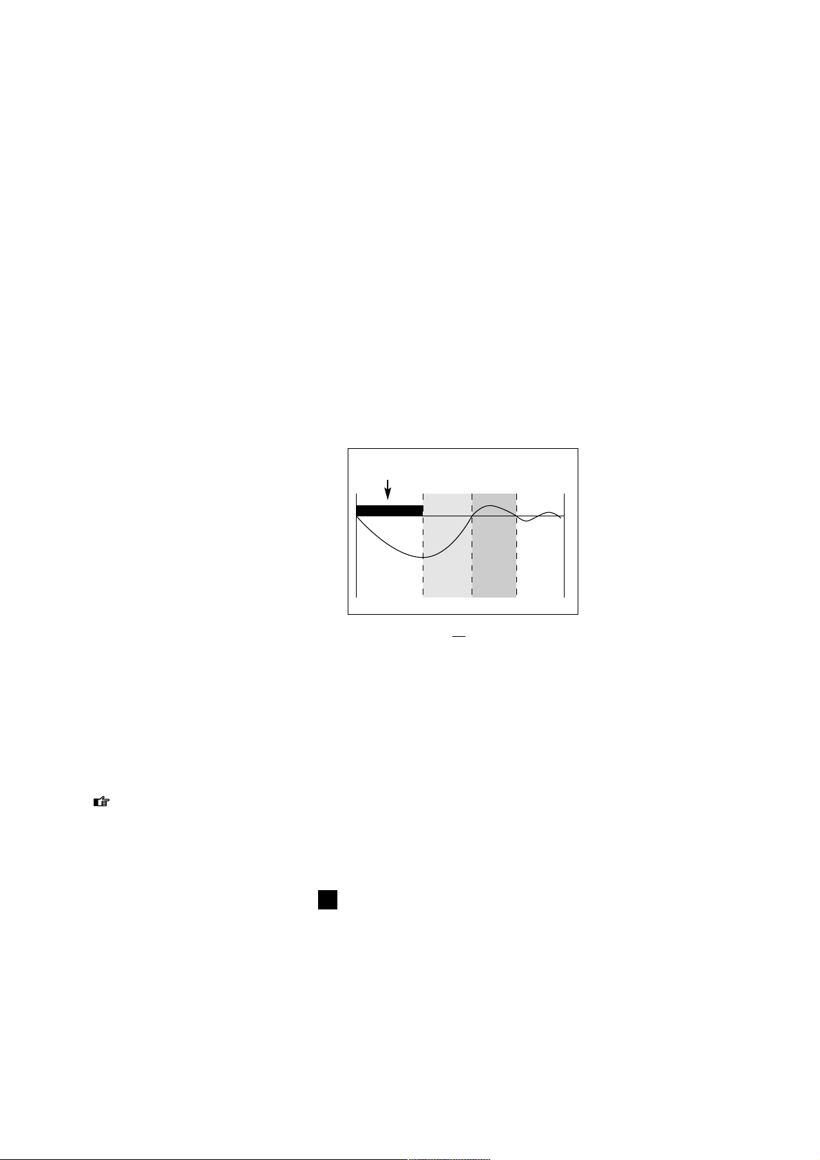
Supercompensatie
Tijdens het trainen brengen we een verstoring teweeg in het lichaam; deze verstoring (hart,
longen, spieren) wordt tijdens de rust hersteld en een stukje verbeterd. Dit principe noemen
we supercompensatie. We worden dus niet sterker van het trainen maar van de rust daarna.
Een volgende training moet komen op het moment dat de supercompensatie curve de nullijn
nog net niet geraakt heeft (fig.25). Om de conditie op een hoger niveau te brengen kan worden
gesteld dat minimaal drie trainingseenheden per week nodig zijn. Met twee trainingen kan men
de conditie behouden en één training per week is te weinig. Een trainingsplan kan door uzelf of
door een trainer/coach worden samengesteld.
Het is aan te raden om tijdens het gebruik
van de Basic ergotrainer een hartslagmeter
te gebruiken.
Voorbeelden trainingsprogramma’s
Begin een training altijd met een warming-up.
Even 5 tot 10 minuten losfietsen op een klein
verzet en een trapfrequentie van 90/110
omw./min. Tijdens deze warming up kan men
wat rekoefeningen doen (zelfs op de fiets).
Eindig de training met een cooling-down van
5 tot 10 minuten en weer wat rekoefeningen.
Het overslaan van een goede warming-up
en of cooling-down kan leiden tot blessures.
De Tacx Basic is bij uitstek geschikt voor
specifieke trainingen. Alvorens te beginnen
met een trainingsprogramma is het raadzaam een conditietest te doen zodat u weet welk
vermogen u kunt leveren en welke hartslagen daarbij horen. Maak vervolgens, eventueel samen
met een trainer/coach, een plan (jaar-, maand- en weekplan) naar uw eigen doelstellingen,
niveau en mogelijkheden. In het jaarplan traint u alle seizoenen op de Basic (dus niet alleen bij
slecht weer). Trainen op vermogen maakt u sterker, sneller en beter. U leert klimmen, sprinten,
een krachttraining afwerken (zie voorbeeld) en zelfs een tijdrit simuleren.
Met de Basic is het ook mogelijk zelf een "Conconi" test, de Astrandtest of de PWC test
(Physical Work Capacity) uit te voeren. De laatste twee testen kunt u vinden op de Tacx
website waar u na het invoeren van de gegevens direct de uitslag kunt ontvangen.
Trainingsadviezen en de laatste ontwikkelingen: www.tacx.nl.
25
0
trainingsarbeid
herstel
super
compensatie
NL
Page 15

Trainingsadvies
15
Hersteltraining
tijd (min.) slope omw. (rpm) verzet bijzonderheden
3 1 100 kleinste lekker draaien/hoge snelheid
3 1 100 1 zwaarder lekker draaien/hoge snelheid
3 1 100 1 zwaarder lekker draaien/hoge snelheid
3 1 100 1 zwaarder lekker draaien/hoge snelheid
3 1 100 1 zwaarder lekker draaien/hoge snelheid
3 1 100 1 zwaarder lekker draaien/hoge snelheid
3 1 100 1 lichter lekker draaien/hoge snelheid
3 1 100 1 lichter lekker draaien/hoge snelheid
3 1 100 1 lichter lekker draaien/hoge snelheid
3 1 100 1 lichter lekker draaien/hoge snelheid
3 1 100 1 lichter lekker draaien/hoge snelheid
3 1 100 kleinste lekker draaien/hoge snelheid
36
Eventueel het geheel nog eens herhalen op stand 2 met twee minuten telkens en nog eens op
stand 3 met één minuut herhaling.Voor de afwisseling kunt u natuurlijk ook op 80, 90, 110 of 120
omwentelingen gaan fietsen.
Krachttraining
tijd (min.) watt omw. (rpm) verzet bijzonderheden
3 80 80/90 vrij warming-up/rustig losrijden
4 140 100 klein snelheid verhogen
3 180 100 klein snelheid verhogen
2 200 100 klein snelheid verder verhogen
1 240 90 klein snelheid nog verder verhogen
3 80 120 klein rustig rijden
4 180 60 groot lage snelheid/blijven zitten
3 200 70 groter lage snelheid/blijven zitten
2 220 80 groter lage snelheid/blijven zitten
1 260 70 groter staan op de pedalen
5 80 80/90 vrij cool-down
31
Het vermogen is bij deze krachttraining is makkelijk aan te passen aan de individuele
eisen/vaardigheden van de renner. Start niet te zwaar en werk het gehele programma af.
Heuveltraining
tijd (min.) slope omw. (rpm) verzet bijzonderheden
4 2 80/90 vrij lekker draaien/constante snelheid
3 3 > 80 vrij probeer snelheid hoog te houden
1 7 60 53-14 staan op de pedalen!
5 1 > 100 42-16 hoge trapfrequentie
2 5 > 80 53-15 zitten/staan om de 30" afwisselen
2 6 90/100 42-16 blijven zitten
5 1 110/130 42-16 hoge trapfrequentie
10
1 vrij vrij cooling-down
32
NL
Page 16

Foutmeldingen
16
Mogelijk probleem
1 Het frame van de Basic staat
niet vlak.
2 Het frame is niet goed
gemonteerd.
3 De fiets staat niet goed in
het frame.
4 Frame niet volledig uitgeklapt.
1 De bandenspanning te laag.
2 De rol is niet goed tegen de
band aangedrukt.
1 Er is een profielband
gemonteerd.
2 Er zit een steentje (tikken!)
in de band.
1 De omgevingstemperatuur is
te laag of te hoog.
2 De zichthoek van het display
is niet goed.
3 De computer heeft geen
goede verbinding met de
wervelstroomrem.
4 Zweet kan de printplaat van
de computer aangetast
hebben.
5 De printplaat van de wervel-
stroomrem is doorgebrand.
1 De Basic is tijdens het weg-
schrijven van waarden onderbroken b.v. door uitschakelen
netspanning tijdens training.
Oplossing
1 Plaats Basic op een vlakke vloer.
2 Controleer of alle bouten en moeren
goed vast zitten.
3 Controleer of bijgeleverde blockage is
gemonteerd.
4 Klap frame volledig uit.
1 Controleer bandenspanning, min.6 atm.
2 Draai rol stevig tegen de band.
1 Monteer band met geheel of gedeel-
telijk glad bandenprofiel.
2 Controleer band.
1 Gebruik de Basic bij een omgevings-
temperatuur tussen 5º C en 35º C
(40ºF en 95ºF)
2 Richt het display zo, dat er loodrecht
op kan worden gekeken.
3 Controleer de kabel en de contacten
van de stekker in de computer en de
wervelstroomrem. Deze kunnen vuil,
geoxideerd of verbogen zijn.
4 De printplaat moet worden
vervangen.
5 De printplaat moet worden
vervangen.
1 Volledig resetten computer: Houdt
gedurende 5 seconden, terwijl u de
stekker onder in de computer steekt
de SET toets ingedrukt en druk vervolgens tweemaal op de Mode toets.
Storing
1 De opstelling van de
Basic wiebelt
2 Er blijft rubber
van de fietsband
aan de rol kleven
3 Er ontstaat veel
lawaai door het
fietsen
4 Display is slecht of
niet leesbaar
5 Foutieve waarden
op display
5 FOUTMELDINGEN
Trainer
NL
Basic computer en wervelstroomrem
Page 17

Foutmeldingen
17
NL
Oplossing
1 Controleer de kabel en de contacten
van de stekker in de computer en de
wervelstroomrem. Deze kunnen vuil,
geoxideerd of verbogen zijn.
2 De Basic werkt correct tussen
220-230 V/50Hz.
3 De deksel van de wervelstroomrem
moet vervangen worden.
4 De printplaat moet worden vervan-
gen.
1 Vervang de ketting.
2 Zorg ervoor dat de achterband goed
hard is opgepompt.
3 Na ongeveer drie minuten fietsen is
de wervelstroomrem opgewarmd.
4 Gebruik de Basic bij een omgevings-
temperatuur tussen 5º C en 35º C
(40ºF en 95ºF)
1 Sluit de sensor aan of monteer een
goede magneet.
2 Zorg dat de afstand tussen de sensor
en de magneet ongeveer 3 mm is.
3 Sluit een nieuwe sensor aan.
4 Controleer of de stekker volledig in
de aansluiting zit.
1 Controleer de kabel en de contacten
van de stekker in de computer en de
wervelstroomrem.
2 De afstelknop van de wervelstroom-
rem bijstellen, zodat slippen van de
band niet mogelijk is.
3 Er zal een nieuwe printplaat in de
wervelstroomrem moeten worden
gemonteerd.
Mogelijk probleem
1 De wervelstroomrem heeft
geen of te weinig remwerking.
2 De netspanning is te laag.
3 Enkele magneten van de wer-
velstroomrem zitten los.
4 De printplaat van de wervel-
stroomrem is doorgebrand.
1 De fietsketting is versleten.
2 De bandenspanning is te laag.
3 De wervelstroomrem is nog
niet opgewarmd.
4 De omgevingstemperatuur is
te laag.
1 De cadanssensor is niet aan-
gesloten of de magneet is uit
de magneethouder gevallen.
2 De sensor is buiten het bereik
van de magneet gemonteerd.
3 In de kabel van de cadans-
sensor zit een breuk.
4 De stekker van de sensor zit
niet goed in de aansluiting van
de wervelstroomrem.
1 De snelheidsimpulsen berei-
ken de computer niet.
2 Het fietswiel raakt de rol van
de wervelstroomrem niet.
3 De snelheidssensor in de
wervelstroomrem is defect.
Storing
6 U ervaart dat het
fietsvermogen lager
aanvoelt dan het
display aangeeft
7 U ervaart dat het
fietsvermogen hoger
aanvoelt dan het
display aangeeft
8 De trapfrequentie
blijft 0
9 De fietssnelheid
blijft 0
Page 18

EU-CONFORMITEITSVERKLARING
In de zin van de EG-machinerichtlijn 93/68EEG bijlage II A.
Hiermede verklaart Technische Industrie Tacx bv, Rijksstraatweg 52, 2241 BW Wassenaar,
Nederland, dat de hierna vermelde machine op grond van haar concipiëring en constructie alsmede in de door ons in omloop gebrachte uitvoering beantwoordt aan de desbetreffende veiligheids- en gezondheids voorschriften van de EG-richtlijn. Na een wijziging aan de machine die
niet in overleg wordt uitgevoerd, verliest deze verklaring haar geldigheid.
Produkt: CycleForce
Type: Basic
Aansluitingsgegevens: 220 V AC 50 Hz
Desbetreffende EG-richtlijn:
EG-Machinerichtlijn (89/392/EEG), versie 93/68/EEG, EG-Laagspanningsrichtlijn (73/23/EU)
EG-Richtlijn Electromagnetische Compatibiliteit (89/336/EEG), versie 93/31/EEG.
Toegepaste geharmoniseerde normen:
EN 50081-1, EN 55022 (1993) klasse B, EN 50082-1, EN 61000-4-2; EN 61000-4-3; EN
61000-4-4; EN 61000-4-5 en EN 61000-4-6.
Door interne maatregelen is ervoor gezorgd dat de standaardapparaten steeds beantwoorden
aan de eisen van de actuele EG-richtlijn en de aangewende normen.
Wassenaar, 23-09-2000
J.H.J. Tacx
NL
Snelheid (Km/h of Mi/h)
Actuele snelheid
kilometers of mijlen per uur
0,1 tot 99,9 Km/h of Mi/h
Stopwatch, gefietste tijd
capaciteit: 8 uren, 59 minuten, 59 seconden
TRP ritafstand
capaciteit 999,9 kilometers of mijlen
ODO totale afstand
capaciteit 99.999,9 kilometers of mijlen
MAX maximum snelheid
capaciteit 99,9 kilometers of mijlen per uur
AVS gemiddelde snelheid
capaciteit 99,9 kilometers of mijlen per uur
Vermogen (watt)
Actueel vermogen
capaciteit 2-999 watt
AVS gemiddeld vermogen
capaciteit 999 watt
MAX maximum vermogen
capaciteit 999 watt
TRP ritverbruik in Kcal
capaciteit 999,9 kilocalorieën
Technische specificaties & EU-conformiteitsverklaring
18
6 TECHNISCHE SPECIFICATIES
Trapfrequentie (cad)
Actuele trapfrequentie (cadans)
0-250 trapomwentelingen per minuut
AVS gemiddelde trapfrequentie
tot 250 trapomwentelingen per minuut
MAX maximale trapfrequentie
tot 250 trapomwentelingen per minuut
TRP trapomwentelingen per rit
tot 99.999 trapomwentelingen
Diversen
24-uurs klok
23 uur: 59 minuten:59 seconden
SLOPE, hellingswaarde
-4 tot +9 in stappen van 1
WATT instelbaar vermogen
0-999 watt in stappen van 10
Temperatuurbereik
5 tot 35 graden Celcius
(40 tot 95 graden Fahrenheit)
Page 19

Garantiebepalingen
19
7 GARANTIEBEPALINGEN
Tacx produkten worden vervaardigd in overeenstemming met de hoogste kwaliteitsnormen.
Op Tacx produkten is voor de periode van één (1) jaar vanaf de aankoopdatum een garantie
tegen produktie- en materiaalfouten van toepassing. Bewaar de kassabon, want dit is uw
aankoopbewijs!
De garantie vervalt indien het produkt aantoonbare sporen vertoont van:
1 gebruik voor een ander doel dan waarvoor bestemd
2 onoordeelkundige gebruik, reparatie of demontage
3 beschadigingen ten gevolge van ongevallen en verwaarlozing
4 aantasting van de printerplaat van de computer door transpiratievocht en/of condens
5 schade die optreedt gedurende de verzending of het vervoer van het produkt
Onderdelen die bij normaal gebruik slijtage vertonen vallen niet onder de garantie.
Verzendkosten
- verzendkosten naar de Tacx dealer of Tacx Service Centre zijn voor eigen rekening
- reparaties worden op kosten van het Tacx Service Centre retour gestuurd
Procedure
- Wanneer het produkt bij normaal gebruik om enigerlei reden niet naar behoren functioneert,
breng deze dan met het bewijs van aankoop (kopie) en het ingevulde serviceformulier terug
naar uw handelaar. U kunt het ook direct naar het Tacx Service Centre sturen in uw land. De
Service Centres staan vermeld in de Tacx catalogus, de gebruikshandleidingen en op de Tacx
website.
- Volg instructies voor retourzending. Het Tacx Service Centre kan alleen retourzendingen in
behandeling nemen die vergezeld zijn van een ingevuld service formulier.
- Als wordt vastgesteld dat het produkt onder garantie valt zal het Service Centre dit binnen 30
dagen na ontvangst kostenloos repareren of vervangen.
- De vaststelling of een produkt onder garantie valt berust alleen bij de Technische Industrie Tacx
bv. Wanneer het produkt niet onder garantie valt dan zal het worden gerepareerd en worden
de kosten berekend. Wanneer de kosten van de reparatie hoger zijn dan 50,00 Euro ontvangt u
vooraf een prijsopgave. Na ontvangst van uw antwoord wordt het produkt gerepareerd of in de
oorspronkelijke staat retour gestuurd.
Instructies voor retourzending
1 Stuur alleen de onderdelen, van het Tacx produkt, die voor reparatie in aanmerking komen.
2 Pak alles zorgvuldig in de originele verpakking in. Transportbeschadigingen zijn voor uw rekening.
3 Vul het serviceformulier volledig en duidelijk in.
4 Stuur een kopie van de aankoopbon mee.
5 Stuur het pakket gefrankeerd - en eventueel verzekerd - naar het Tacx Service Centre in uw
land.
Aansprakelijkheid
- Technische Industrie Tacx bv behoudt zich het recht voor om de produkten zonder voorafgaand
bericht aan te passen, te verbeteren of de vervaardiging ervan te beëindigen.
- Tacx bv zal niet verplicht zijn om nieuwe aspecten/elementen aan te brengen in eerder verkoch
te producten, zelfs indien producten krachtens een garantie worden geretourneerd.
- Tacx bv mag defecte onderdelen vervangen door gelijksoortige onderdelen van gelijke kwaliteit
indien identieke onderdelen niet beschikbaar zijn.
- Tacx bv kan op geen enkele wijze aansprakelijk worden gesteld voor directe, incidentele of bij
zondere schade die voortvloeit uit of samenhangt met het gebruik van de producten.
NL
Page 20

20
Service Formulier
SERVICE FORMULIER
Lees alvorens het produkt in te sturen de foutmeldingen in de bijbehorende handleiding en loop de
veelgestelde vragen op de website door. Gebruik dit formulier en vul alle gegevens duidelijk in om
voor service in aanmerking te komen.
Stuur het volledig ingevulde service formulier, samen met een kopie van de aankoopbon, naar uw
dichtsbijzijnde Tacx Service Centre.
Naam, voorletters . . . . . . . . . . . . . . . . . . . . . . . . . . . . . . . . . . . . . . . . . . . . . . . . . . . . . . . . . . . . . . . . . . . . . . . . . . . . . . . . . . . . . . . . . . . . . . . . . . . . . . . . . . . . . . . . . . . . . . . . . . . . . . . . . . . . . . . . .
Adres . . . . . . . . . . . . . . . . . . . . . . . . . . . . . . . . . . . . . . . . . . . . . . . . . . . . . . . . . . . . . . . . . . . . . . . . . . . . . . . . . . . . . . . . . . . . . . . . . . . . . . . . . . . . . . . . . . . . . . . . . . . . . . . . . . . . . . . . . . . . . . . . . . . . . . . . . . . . . . . .
Postcode . . . . . . . . . . . . . . . . . . . . . . . . . . . . . . . . . . . . . . . . . . . . . . . . . . . . . . . . . . . . . . . . . . . . . . . . . . . . . . . . . . . . . . . . . . . . . . . . . . . . . . . . . . . . . . . . . . . . . . . . . . . . . . . . . . . . . . . . . . . . . . . . . . . . . . . . . .
Plaats . . . . . . . . . . . . . . . . . . . . . . . . . . . . . . . . . . . . . . . . . . . . . . . . . . . . . . . . . . . . . . . . . . . . . . . . . . . . . . . . . . . . . . . . . . . . . . . . . . . . . . . . . . . . . . . . . . . . . . . . . . . . . . . . . . . . . . . . . . . . . . . . . . . . . . . . . . . . . . . .
Land . . . . . . . . . . . . . . . . . . . . . . . . . . . . . . . . . . . . . . . . . . . . . . . . . . . . . . . . . . . . . . . . . . . . . . . . . . . . . . . . . . . . . . . . . . . . . . . . . . . . . . . . . . . . . . . . . . . . . . . . . . . . . . . . . . . . . . . . . . . . . . . . . . . . . . . . . . . . . . . . .
Te l e f o o n . . . . . . . . . . . . . . . . . . . . . . . . . . . . . . . . . . . . . . . . . . . . . . . . . . . . . . . . . . . . . . . . . . . . . . . . . . . . . . . . . . . . . . . . . . . . . . . . . . . . . . . . . . . . . . . . . . . . . . . . . . . . . . . . . . . . . . . . . . . . . . . . . . . . . . . . . . .
Model: Tacx Basic
Aankoopdatum ................................................................................................................................
Computer Serienummer . . . . . . . . . . . . . . . . . . . . . . . . . . . . . . . . . . . . . . . . . . . . . . . . . . . . . . . . . . . . . . . . . . . . . . . . . . . . . . . . . . . . . . . . . . . . . . . . . . . . . . . . . . . . . . . . . . . . . . . . . . . . . .
Aankoopbon meegestuurd (kopie)?
Garantie verlopen?
ja nee
ja nee
Omschrijving van de klacht: . . . . . . . . . . . . . . . . . . . . . . . . . . . . . . . . . . . . . . . . . . . . . . . . . . . . . . . . . . . . . . . . . . . . . . . . . . . . . . . . . . . . . . . . . . . . . . . . . . . . . . . . . . . . . . . . . . . . . . . . .
. . . . . . . . . . . . . . . . . . . . . . . . . . . . . . . . . . . . . . . . . . . . . . . . . . . . . . . . . . . . . . . . . . . . . . . . . . . . . . . . . . . . . . . . . . . . . . . . . . . . . . . . . . . . . . . . . . . . . . . . . . . . . . . . . . . . . . . . . . . . . . . . . . . . . . . . . . . . . . . . . . . . . . . . . .
. . . . . . . . . . . . . . . . . . . . . . . . . . . . . . . . . . . . . . . . . . . . . . . . . . . . . . . . . . . . . . . . . . . . . . . . . . . . . . . . . . . . . . . . . . . . . . . . . . . . . . . . . . . . . . . . . . . . . . . . . . . . . . . . . . . . . . . . . . . . . . . . . . . . . . . . . . . . . . . . . . . . . . . . . .
. . . . . . . . . . . . . . . . . . . . . . . . . . . . . . . . . . . . . . . . . . . . . . . . . . . . . . . . . . . . . . . . . . . . . . . . . . . . . . . . . . . . . . . . . . . . . . . . . . . . . . . . . . . . . . . . . . . . . . . . . . . . . . . . . . . . . . . . . . . . . . . . . . . . . . . . . . . . . . . . . . . . . . . . . .
. . . . . . . . . . . . . . . . . . . . . . . . . . . . . . . . . . . . . . . . . . . . . . . . . . . . . . . . . . . . . . . . . . . . . . . . . . . . . . . . . . . . . . . . . . . . . . . . . . . . . . . . . . . . . . . . . . . . . . . . . . . . . . . . . . . . . . . . . . . . . . . . . . . . . . . . . . . . . . . . . . . . . . . . . .
Andere mededelingen voor Tacx Service Centre: . . . . . . . . . . . . . . . . . . . . . . . . . . . . . . . . . . . . . . . . . . . . . . . . . . . . . . . . . . . . . . . . . . . . . . . . . . . . . . . . . . .
. . . . . . . . . . . . . . . . . . . . . . . . . . . . . . . . . . . . . . . . . . . . . . . . . . . . . . . . . . . . . . . . . . . . . . . . . . . . . . . . . . . . . . . . . . . . . . . . . . . . . . . . . . . . . . . . . . . . . . . . . . . . . . . . . . . . . . . . . . . . . . . . . . . . . . . . . . . . . . . . . . . . . . . . . .
. . . . . . . . . . . . . . . . . . . . . . . . . . . . . . . . . . . . . . . . . . . . . . . . . . . . . . . . . . . . . . . . . . . . . . . . . . . . . . . . . . . . . . . . . . . . . . . . . . . . . . . . . . . . . . . . . . . . . . . . . . . . . . . . . . . . . . . . . . . . . . . . . . . . . . . . . . . . . . . . . . . . . . . . . .
. . . . . . . . . . . . . . . . . . . . . . . . . . . . . . . . . . . . . . . . . . . . . . . . . . . . . . . . . . . . . . . . . . . . . . . . . . . . . . . . . . . . . . . . . . . . . . . . . . . . . . . . . . . . . . . . . . . . . . . . . . . . . . . . . . . . . . . . . . . . . . . . . . . . . . . . . . . . . . . . . . . . . . . . . .
. . . . . . . . . . . . . . . . . . . . . . . . . . . . . . . . . . . . . . . . . . . . . . . . . . . . . . . . . . . . . . . . . . . . . . . . . . . . . . . . . . . . . . . . . . . . . . . . . . . . . . . . . . . . . . . . . . . . . . . . . . . . . . . . . . . . . . . . . . . . . . . . . . . . . . . . . . . . . . . . . . . . . . . . . .
NL21D
Page 21

Inhalt der Verpackung
Kontrollieren Sie, ob die Packung alle
unten aufgeführten Teile enthält
- Basic computer
- Tacx CycleForce Basic
- Wirbelstrombremse
- Kabel und Trittfrequenzsensor
- Betriebsanleitung
T1424.01
2x
T1424.02
2x
T1465.012xT1465.08
2x
T1402
1x
T1408.11
1x
T1410.021xT1410.04
2x
T1410.06
1x
T1423.15
2x
T1424.03
2x
T1461.19
2x
T1615.18
1x
T1466.01
1x
T1466.021xT1466.03
1x
T1466.04
1x
T1260.074xT1461.19
4x
T2459.03
4x
- T1466 Montagekit für Raddurchmesser-Anpassung
- T1615 Montagebeutel Trainer
- Füße und Verschlußkappen
Page 22

22
INHALT
1 Montage des Basic
Montage des Trainers 23
Anschließen des Computers 25
2 Einmaliges einstellen des Computers
Ändern der Geschwindigkeitsanzeige 26
Einstellen des Körpergewichts 26
Einstellen der 24-Stunden-Uhr 26
3 Benutzung des Computers
MODE-Funktionen bei Km/h (Mi/h) 27
Rückstell-Funktionen mit der MODE-Taste 28
Funktionen mit den + und - Tasten 28
MODE-Funktion bei WATT 29
MODE-Funktion bei CAD 29
Set-Funktion bei SLOPE (Steigung) 30
Set-Funktion bei WATT prg (Programmierte Leistung) 30
Leistung (W) = Kraft x Geschwindigkeit 31
4 Trainingsempfehlungen
Superkompensation 32
Beispiele für Trainingsprogramme 32
5 Fehlersuche 34
6 Technische Daten &
EG-Konformitätserklärung 36
7 Garantiebestimmungen
Ablauf 37
Instruktionen zum einschicken 37
Serviceformular 38
Erklärung der Symbole
Wichtig - also aufpassen
Wichtiger Tip, gut zu wissen
Inhalt
D
Page 23

Montage des Basic
23
D
1 MONTAGE DES BASIC
Der Ergotrainer Basic setzt sich zusammen aus dem zusammenklappbaren Rahmen,
worauf Sie Ihr Fahrrad montieren (der CycleForce Trainer ist standardmäßig für Renn- und
Trekking-Räder geeignet, sowie für Mountainbikes mit einem Laufraddurchmesser zwischen
630 und 690 mm) und dem Basic Computer.
Montage des Trainers
Der Trainer braucht nur einmal aufgebaut und eingestellt zu werden; hierzu
gehen Sie folgendermaßen vor:
1 Drücken Sie die Mutter A in die Rohrverschlußkappe B und schieben Sie diese
in das Rahmenrohr ein (Fig. 1).
2 Bringen Sie den Fuß C mit der Schraube D am Rahmen an. Drehen Sie die
Schraube D nur so fest, daß sich der Fuß noch verstellen läßt.
3 Stellen Sie den Trainer aufgeklappt auf einen festen Untergrund. Der Trainer
läßt sich auf- und einklappen, indem Sie den Handgriff E vollständig eindrücken (Fig. 1).
4 Drehen Sie den Fuß C in die richtige Stellung (Fig. 2). Ziehen Sie die Schraube D fest und
bringen Sie das Antirutschgummi F an (Fig. 4).
5 Befestigen Sie die zwei Gummiringe G und den Bolzen K an dem Hebel H (Fig. 3). Der so
vorbereitete Hebel H läßt sich nun an dem Rahmen des Heimtrainers anbringen. Schieben Sie
nun die Wirbelstrombremse I auf den Bolzen K des Hebels und drehen Sie die Schraube J so
fest, daß sich die Bremse noch bewegen kann (Fig. 4).
6 Tauschen Sie den Schnellspanner Ihres Hinterrads gegen die mitgelieferte Tacx-Befestigung X
aus. Hierdurch wird eine optimale Klemmkraft und Stabilität gewährleistet. Setzen Sie das
Fahrrad in den Trainer und stellen Sie die Flügelschraube L so ein, daß sich der Schnellspanner M
ohne Kraftaufwand schließen läßt. Wenden Sie keine Gewalt an, Sie könnten Schäden verursachen!
7 Sichern Sie die Flügelschraube L durch Festdrehen der Flügelmutter N.
E
A
D
C
B
C
1
2
J
LN
X
M
E
I
K
H
F
4
H
K
G
3
10 mm
13 mm (2x)
13 mm (2x)
Page 24

24
Montage des Basic
D
8 Mit dem Hebel H läßt sich die Rolle der Wirbelstrombremse gegen den Reifen des Fahrrades
klappen (Fig. 5 & 6). Ist der Hebel H zugeklappt, kann man nun über den Knauf R den Druck
der Rolle auf den Reifen des Hinterrades einstellen. Achten Sie darauf, daß die Rolle straff gegen
den Reifen drückt, um ein Durchrutschen des Reifens während des Trainings zu vermeiden.
Montageanpassung für Fahrräder mit einem anderen Laufrad-Durchmesser
Bevor die komplette Hebeleinheit an den Rahmen montiert wird (siehe Punkt 5), müssen
die Kunststoff-Verlängerungs-Streifen befestigt werden.
Raddurchmesser 610 - 640 mm: befestige die Streifen W mit 4 Schrauben, Muttern und
Ringen. (Fig. 7)
Raddurchmesser 690 - 720 mm: befestige Streifen Z (Fig. 8)
Hinweis
- Prüfen Sie, bevor Sie den CycleForce benutzen, ob der Handgriff E nach dem Aufklappen des
Trainers vollständig zurückgefedert ist. Hiermit wird eine Beschädigung des Rahmens vermieden.
- Sorgen Sie dafür, daß das Gerät bei der Montage nicht auf das Schwungrad fällt. Dadurch könnte
in der Achse eine Unwucht entstehen, die Schwingungen verursachen würde.
- Achten Sie darauf, daß der Reifen stark aufgepumpt ist (mindestens 6 bar).
- Bei einem ATB ist ein ganz oder fast ganz glatter Reifen vorzuziehen, denn Reifen mit Profil
machen zu viel Lärm und können obendrein schlüpfen.
- Bremsen Sie beim Fahren auf dem CycleForce Basic nie abrupt ab. Das Schwungrad dreht sich
dabei weiter, der Hinterreifen rutscht und würde unnötig verschleißen.
- Kontrollieren Sie regelmäßig, ob alle Schrauben und Muttern des Trainers noch gut fest sitzen.
- Zwar kann das Gerät, wie Tests gezeigt haben, auch bei extremer Belastung nicht überhitzt
werden. Bei ständigem, intensiven Gebrauch kann das Gehäuse des Bremsmagneten allerdings
ziemlich heiß werden. Berühren Sie es also nicht sofort nach Gebrauch, sondern lassen sie es
zunächst abkühlen.
H
R
H
5 6
W
W
H
Z
Z
H
7 8
Page 25

25
Montage des Basic
Anschließen des Computers
Nachdem Sie das Fahrrad in den Trainer montiert haben, können Sie den Computer
folgender maßen anschließen:
1 Bringen Sie den Computer mit Hilfe der beiden Gummiklemmbänder P an der Lenkstange an
(Fig. 4).
2 Schließen Sie den Computer mit dem Kabel Q ans Gerät an. Verlegen Sie das Kabel so, daß Sie
es beim Fahren nicht berühren können (beispielsweise mit den Schuhen auf den Pedalen).
3 Bringen Sie den kleinen Impulsmagnet R an der Innenseite der linken Tretkurbel an (Fig. 5).
4 Bringen Sie den Magnetsensor S für die Impulsmessung an der Unterseite der linken
Hinterradgabel an, und zwar so, daß sich der Sensor in Höhe des Magneten befindet und dabei
von diesem ungefähr 3 mm entfernt ist. Stecken Sie das Sensorkabel in das Gerät ein und achten
Sie darauf, daß das Kabel nicht am Hinterrad schleift.
5 Stecken Sie den Netzstecker in eine Steckdose. Kontrollieren Sie den Empfang des
Trittfrequenzmessers, indem Sie rückwärts treten. Auf dem Display erscheint das Wort CAD.
Der Basic ist betriebsbereit.
Schweiß und Kondenswasser können die Leiterplatte im Computer angreifen. Benutzen Sie den
Basic nicht in feuchter Umgebung und trocknen Sie das Display, wenn nötig, nach Gebrauch ab.
Dadurch wird eine unnötige Beschädigung vermieden. Bei unsachgemäßem Gebrauch und/oder
unrichtiger Pflege erlischt der Garantieanspruch.
5
P
P
4
D
S
R
R
S
Q
Page 26

Einmaliges Einstellen des Computers
26
Nachdem das Gerät eingesteckt ist, leuchtet das Display als
Prüfsignal kurz auf. Anschließend schaltet sich das normale
Programm ein (Fig. 6).
Jetzt könnten Sie auf Ihr Fahrrad steigen und sofort losfahren,
wenn Sie nicht vorher einmalig Ihr Körpergewicht in das
Programm eingeben müßten. Standardmäßig ist die
Geschwindigkeitsanzeige auf Km/h und das Körpergewicht auf
75 kg eingestellt. Wenn Sie die Geschwindigkeitsanzeige nicht
ändern wollen und Ihr Gewicht eingegeben haben, machen
Sie sofort mit dem normalen Programm weiter.
Ändern der Geschwindigkeitsanzeige
Wenn Sie die Geschwindigkeitsanzeige und das Gewicht einstellen wollen, halten Sie gleichzeitig die Tasten SET und MODE 6
Sekunden lang gedrückt. Danach erscheint die Anzeige SET UP
(Fig. 7). Durch Drücken der + oder - Taste können Sie von Km/h
auf Mi/h (englische Meilen pro Stunde) umschalten und umgekehrt (Fig. 8). Sie speichern Ihre Wahl durch Drücken der Taste
MODE.
Einstellen des Körpergewichts
Anschließend wird als Körpergewicht 75 kg angezeigt (Fig. 9).
Auch hier können Sie mit den + und - Tasten den Wert ändern,
und zwar in Schritten von 1 kg (Fig. 10). Die Gewichtsangabe
benötigt der Computer, um die von Ihnen beim Fahren gelieferte
Leistung korrekt bestimmen zu können, denn diese hängt u.a.
vom beförderten Gewicht ab. Das Gewicht läßt sich zwischen
40 und 120 kg einstellen.
Nachdem Sie ihr Gewicht eingegeben haben, speichern Sie auch
diesen Wert durch Drücken der Taste MODE. Der Wert bleibt
auch beim Ausschalten des Ergotrainers gespeichert, so daß er
vom Programm beim nächsten Mal wieder benutzt wird. Sie können den Wert jedoch jederzeit nach obiger Beschreibung ändern,
beispielsweise, wenn eine andere Person den Ergotrainer
benutzt.
Einstellen der 24-Stunden-Uhr
Nach dem Einstellen des Gewichts können Sie, wenn Sie wollen,
die Zeitanzeige in eine 24-Stunden-Anzeige ändern. Wenn Sie
dies nicht wollen, drücken Sie zweimal die MODE-Taste und
kehren ins normale programm zurück. Die Zeitanzeige taucht
während des Fahrens nicht mehr auf.
Wenn Sie doch die 24-Stunden-Anzeige benutzen wollen, stellen
Sie mit den + und - Tasten zunächst die Stundenzahl ein, drücken dann MODE und stellen danach mit +/- Tasten die Minuten
ein. Noch einmal MODE drücken, die Uhr ist eingestellt und Sie
kehren ins normale Programm zurück. Wenn Sie die anderen
Funktionen durchlaufen, kehrt auch die Zeitanzeige zurück.
Beim Ausschalten des Computers wird auch die Uhr ausgeschaltet, das heißt, daß sie nach dem nächsten Einschalten bei Bedarf
mit der SET-UP-Prozedur wieder eingestellt werden muß.
KG
9
WATT ETM
SLOPE KM/h
KM/h
MI/h
6
7
8
D
2 EINMALIGES EINSTELLEN DES COMPUTERS
Page 27

Benutzung des Computers
27
KG
10
3 BENUTZUNG DES COMPUTERS
Nachdem Sie die Computereinstellungen vorgenommen haben,
können Sie "losfahren". Alle hiernach beschriebenen Handlungen
können Sie sowohl "während der Fahrt" als auch im Stillstand
ausführen.
Der Basic registriert 3 Arten von Daten: die erste bezieht sich auf
die Fahrgeschwindigkeit und wird als erste besprochen, die beiden anderen, Leistung und Trittfrequenz, werden anschließend
erläutert.
MODE-Funktionen bei Km/h (oder Mi/h)
Mit der MODE-Taste werden die einzelnen Fahrfunktionen
aufgerufen. Jedesmal, wenn diese Taste einmal gedrückt wird,
erscheinen nachein-ander: ETM, TRP, ODO, MAX, AVS
(siehe Blockdiagramm). Auch die 24-Stunden-Anzeige steckt in
diesem Datenturnus, wenn Sie sie vorher eingestellt haben.
ETM (Stoppuhr)
Sie fangen rechts oben mit ETM, der Stoppuhr, an (Fig. 11).
ETM ist die Zeit, die gefahren wird, ohne daß der Computer
rückgestellt (RESET), oder ausgeschaltet wird. Die Stoppuhr
registriert nur die gefahrene Zeit. Wenn Sie zwischendurch eine
Pause machen, wird diese Zeit nicht mitgezählt. Wenn Sie den
Computer während des Fahrens ausschalten oder rückstellen,
fängt die Stoppuhr wieder bei “0” an.
TRP (Gefahrene Strecke)
Drücken Sie erneut die MODE-Taste, dann erscheint rechts oben
TRP, die gefahrene Entfernung (Fig. 12). Solange der Computer
nicht rückgestellt oder ausgeschaltet wird, berechnet er die
Fahrtstrecke.
ODO (Gesamtstrecke)
Nochmaliges Drücken der MODE-Taste zeigt rechts oben ODO,
die insgesamt mit dem Ergotrainer “zurückgelegte Strecke”
(Fig. 13). Die ODO-Funktion addiert alle gefahrenen Strecken,
und zwar bis maximal 99.999 km (oder Meilen) und fängt danach
bei Null wieder an.
ETM
Stoppuhr
TRP
Gefahrene
Strecke
ODO
Gesamt-
stecke
MAX
Höchstge-
schwindigkeit
AVS
Durchschnitt
geschwindigkeit
Uhr
MODE
WATT TR P
SLOPE KM/h
WATT
SLOPE KM/h
WATT ODO
SLOPE KM/h
12
13
WATT ETM
SLOPE KM/h
11
D
Page 28
WATT MAX
SLOPE KM/h
14
Benutzung des Computers
28
MAX (Höchstgeschwindigkeit)
Als nächstes erscheint nach Drücken der MODE-Taste rechts
oben MAX, der Betrag der erreichten Höchstgeschwindigkeit
während des Zeit-raums, in dem der Computer nicht rückgestellt
oder ausgeschaltet wurde.
AVS (Durchschnittsgeschwindigkeit)
Nach nochmaligem Drücken der MODE-Taste wird rechts oben
AVS angezeigt, der Durchschnittswert der Geschwindigkeit. Die
Durchschnittsgeschwindigkeit wird für den Zeitraum berechnet,
in dem der Computer nicht rückgestellt oder ausgeschaltet war.
UHR
Wenn Sie sich entschieden hatten, die Uhr zu benutzen, dann
können Sie nach AVS die MODE-Taste noch einmal drücken,
wonach die Uhr-zeit angezeigt wird.
Rückstell-Funktionen mit der MODE-Taste
Wenn Sie während einer Trainingsfahrt einzelne Daten, die bei
den Funktionen ETM, TRP, MAX und AVS gespeichert sind, rückstellen (d.h. wieder auf Null stellen) wollen, halten Sie Ihre Beine
ruhig, achten Sie darauf, daß die Geschwindigkeit Null ist und halten Sie die SET- und die MODE-Taste gleichzeitig 1 Sekunde
gedrückt. Die ODO-Funktion läßt sich nicht rückstellen, sie
schaltet sich bei 99.999 km (oder Meilen) von selbst auf Null.
Funktionen mit den + und - Tasten
Wie oben erwähnt, registriert der Basic drei Arten von Daten:
1 Daten, die mit der Geschwindigkeit zusammenhängen
(Km/h oder Mi/h).
2 Daten, die mit der Leistung zu tun haben (WATT).
3 Daten, die mit der Trittfrequenz zu tun haben (CAD).
Mit den + und - Tasten können Sie diese drei Datenarten nacheinander auf dem Display erscheinen lassen, (siehe lockdiagramm).
WATT (Leistung)
Durch Drücken der + Taste wechselt die Anzeige rechts unten
von Geschwindigkeit (km/h) auf Leistung (WATT), die zur Zeit
gelieferte Leistung (Fig. 16).
CAD (Trittfrequenz)
Nach nochmaligem Drücken der + oder - Taste wechselt die
Anzeige rechts unten von WATT nach CAD, der Trittfrequenz
(Fig. 17).
KM/h WATT CAD
-
+
WATT ETM
SLOPE KM/h
15
MAX
SLOPE WATT
16
WATT MAX
SLOPE CAD
17
D
Page 29

MODE-Funktion bei WATT
Wenn auf dem Display die Leistung (WATT) angezeigt wird, können Sie ebenfalls die MODEFunktionen benutzen. Die Stoppuhr (ETM) läuft selbstverständlich unverändert weiter, aber die
Funktionen TRP, MAX und AVS bedeuten bei der WATT-Anzeige jeweils Gesamtleistung,
maximale Leistung und durchschnittliche Leistung.
Der Ausdruck Gesamtleistung bedarf einer Erläuterung: Wenn der Computer nicht rückgestellt
oder ausgeschaltet wird, multipliziert er die verstrichene Zeit (Stoppuhr) mit der insgesamt
gelieferten Leistung. Das Ergebnis ist die geleistete Arbeit in Kilokalorien (Kcal).
MODE-Funktion bei CAD
Wenn Sie auf dem Display die Trittfrequenz (CAD) erscheinen lassen, dann können Sie mit den
Funktionen TRP, MAX und AVS jeweils die Gesamtzahl der Tretlagerumdrehungen während der
Fahrt, die maximale Trittfrequenz und die durchschnittliche Trittfrequenz sichtbar machen.
Wenn Sie jetzt mit der MODE-Taste und den + und - Tasten experimentieren, können Sie
verschiedene Daten kombinieren. Auf Tastendruck erscheinen schnell und genau die Angaben.
Auf diese Weise werden Sie ziemlich rasch mit der Funktionsweise des Computers vertraut und
innerhalb von 10 Minuten haben Sie gelernt, wie Sie die Angaben finden können, die für Sie am
interessantesten oder wichtigsten sind.
Benutzung des Computers
29
KM/h
WATT
CAD
MODE ETM
TRP
ODO
MAX
AVS
MODE
MODE
MODE
MODE
MODE
ETM
TRP
MAX
AVS
TRP
MAX
AVS
Stoppuhr
Gefahrene Strecke
Gesamtstrecke
Höchstgeschwindigkeit
Durchschnittsgeschwindigkeit
Stoppuhr
Während der Fahrt
umgesetzte Energie
Maximale Leistung
Durchschnittliche Leistung
Tretlagerumdrehungen pro Fahrt
Maximale Trittfrequenz
Durchschnittliche Trittfrequenz
Uhr
Uhr
Uhr
D
Page 30

Benutzung des Computers
30
WATT MAX
SLOPE KM/h
WATT
SLOPE KM/h
MAX
18
19
SET-Funktion bei SLOPE (Steigung)
Wir gehen jetzt zum nächsten Schritt. Das Computerprogramm
des Basic bietet Ihnen außerdem die Möglichkeit, einen
Fahrtwiderstand zu simulieren. Hierzu dient die Funktion SLOPE
(Steigung), mit deren Hilfe eine künstliche Widerstandskraft auf
die Rolle des Ergotrainers ausgeübt wird. Die ausgeübte
Bremskraft hängt von der Drehzahl ab, das heißt, je schneller sich
die Rolle dreht, desto leichter ist es für den Computer, die Rolle
zu abzubremsen, und umgekehrt, je kleiner die Trittfrequenz und
damit die Drehzahl der Rolle ist, desto schwieriger ist das
Bremsen der Rolle. Daher ist die SLOPE -Funktion in 14 einzelne
Stufen unterteilt worden, von -4 über den Wert 0 bis +9. Für
Werte über 0 ist der Stei-gungswiderstand gewichtsabhängig.
Wenn Sie die SET-Taste drücken, beginnt die Steigungsanzeige
(SLOPE) links unten zu blinken, (Fig. 18). Die Standardeinstellung
ist Null. Jetzt können Sie mit den + und - Tasten den Steigungswiderstand von -4 bis +9 einstellen, (Fig. 19). Der eingestellte
Wert wird durch Drücken der MODE-Taste gespeichert.
Man könnte annehmen, daß ein Steigungswiderstand von +9
einem Stei-gungswinkel von +9° und ein Steigungswiderstand
von -4 einem Gefälle von 4° entsprechen. Sie werden einsehen,
daß der Trainer, wenn Sie die Beine nicht bewegen, nicht wie
ein Fahrrad in Wirklichkeit “bergab” von alleine weiterrollt. Die
Widerstandsstufen -4 bis +9 sind angebracht worden, um den
Computer die jeweiligen Berechnungen und Anpassungen an
den Widerstand für die programmierte Leistung ausführen zu
lassen.
SET-Funktion bei WATT prg (Programmierte Leistung)
Schließlich können Sie noch einen Schritt weiter gehen. Wenn Sie
nach dem Drücken der SET-Taste und dem Blinken der Steigung
(Fig. 20) die SET-Taste noch einmal drücken, beginnt die programmierte Leistung (WATT prg) links oben zu blinken (Fig. 21).
In dieser Funktion versucht der Computer, unabhähngig von der
benutzten Übersetzung und der Trittfrequenz, die Bremskraft auf
der Rolle derartig anzupassen, daß Sie immer mit der vorher
eingestellten Leistung in die Pedalen treten. Wenn Sie die
Trittfrequenz ändern, paßt der Computer sofort die Bremskraft
an, so daß Sie weiterhin die gleiche Leistung liefern. Wenn Sie mit
einem anderen Gang fahren, reagiert der Computer sofort und
ändert den Widerstand an der Rolle.
Wenn die Anzeige WATT prg auf dem Display blinkt, können Sie
die programmierte Leistung mit den + und - Tasten in Stufen von
10 W einstellen, (Fig. 22). Die programmierte Leistung ist
standardmäßig bereits auf den Wert 100 W voreingestellt worden,
Sie können diesen Wert jedoch selbst zwischen 0 und 990 W
einstellen. In der Praxis wählen die meisten Radfahrer einen Wert
zwischen 100 und 400 W.
WATT
SLOPE KM/h
KG
MAX
WATT PRG
KM/h
MAX
20
21
D
Page 31

Benutzung des Computers
31
Wenn Sie die programmierte Leistung eingestellt haben, können
Sie diesen Wert durch Drücken der MODE-Taste speichern,
(Fig. 23). Wenn die programmierte Leistung gespeichert worden
ist, erlischt die SLOPE-Ziffer, so lange wie Sie unter dem Titel
WATT prg weiter fahren. Den zuletzt eingegebenen und
gespeicherten Wert der programmierten Leistung merkt sich der
Computer, auch wenn er ausgeschaltet wird. Um die Funktion
“programmierte Leistung” zu verlassen, müssen Sie die SET-Taste
zweimal drücken, wodurch Sie wieder zu SLOPE zurückkehren.
Leistung (W) = Kraft x Geschwindigkeit.
Die von Ihnen programmierte Leistung wird während des
Fahrens vom Computer mit SLOPE angepaßt. Angenommen, Sie
haben eine Leistung von 400 W einprogrammiert und Sie wollen
diese ziemliche große Leistung mit verhältnismäßig geringer Kraft
(z.B. Übersetzung von 39x26) und mit relativ niedriger
Geschwindigkeit (z.B. Trittfrequenz 70) auf die Pedalen bringen.
Bei einer solchen extremen Situation kann die SLOPE-Funktion
nicht mehr für einen ausreichenden Widerstand sorgen, um die
programmierte Leistung zu erreichen. Sie werden erkennen, daß
die WATT-Anzeige rechts unten (die gelieferte Leistung) nicht mit
der programmierten Leistung (WATT prg) übereinstimmt.
Die Anzeige WATT prg. links oben blinkt (Fig. 24) zum Zeichen,
daß Sie sich außerhalb des Arbeitsgebiets des Computers befinden. Wenn Sie Ihre Übersetzung (größer, schwerer) und die
Trittfrequenz (höher) anpassen, werden Sie selbst feststellen, daß
Sie wieder ins Arbeitsgebiet des Computers gelangen. Die
Anzeige WATT prg leuchtet wieder ständig.
Wenn Sie umgekehrt eine ziemlich niedrige Leistung einprogrammiert haben, und Sie versuchen diese mit einer relativ großen
Kraft (z.B. Übersetzung 52x16) und bei hoher Geschwindigkeit
(z.B. Trittfrequenz 100) zu erreichen, wird die von Ihnen gelieferte Leistung logischerweise über der programmierten Leistung liegen. Auch dann befinden Sie sich außerhalb des Arbeitsgebiets
des Computers und die Anzeige WATT prg links oben blinkt.
Passen Sie also die Übersetzung und die Trittfrequenz so an, daß
Sie wieder ins Arbeitsgebiet des Computers kommen.
WATT pr g
KM/h
MAX
24
WATT pr g
KM/h
MAX
WATT pr g
KM/h
MAX
22
23
D
Page 32

Trainingsempfehlungen
32
4 TRAININGSEMPFEHLUNGEN
Bei keiner anderen Sportart werden über längere Zeit hinweg so hohe Kraftanstrengungen vom
Sportler abverlangt wie beim Radrennsport. Lungen, Muskeln und Herz eines Radrennfahrers
werden dermaßen stark beansprucht, daß der Radsport als eine der schwersten Sportarten gilt.
Das Wichtigste, was Sie machen sollten, ist der jährliche Gang zu einem spezialisierten Sportarzt
vor Beginn der neuen Radrennsaison, um sich auf die körperliche Tauglichkeit hin gründlich
untersuchen zu lassen.
Eine mögliche Definition von Training könnte lauten: “Das systematische Zufügen von Reizen,
um die persönliche Leistungsfähigkeit zu erhöhen”. Trainieren tun wir immer mit einem Ziel vor
Augen. Eine mögliche Zielsetzung könnte z.B. sein, sein Körpergewicht zu reduzieren, einen
Radmarathon zu bestehen oder gar Gold zu holen bei einer Meisterschaft. Der “Reiz”, dem wir
uns aussetzen, kann entweder in Form von langem, ruhigem Grundlagentraining oder aber in
Form einer kurzen, schnellen Einheit zugeführt werden. Wichtig ist, daß der Trainingsaufbau mit
System erfolgt. Je weiter die Saison fortgeschritten ist, desto länger, weiter oder sogar höher
(in den Bergen) fahren wir Rad. “Variieren” im Training heißt das Zauberwort, um die Leistungsfähigkeit tatsächlich zu verbessern.
Superkompensation
Während des Trainings verursachen wir eine Störung im Körper; diese Störung (bei Herz, Lunge,
Muskulatur) wird während der Regenerationsphase wieder repariert und sogar ein wenig verbessert. Dieses Prinzip wird “Superkompensation” genannt. Sachlich betrachtet werden wir also
nicht besser durch das Trainieren, sondern vielmehr durch die Ruhe danach. Die nächste
Trainingseinheit muß genau dann erfolgen, wenn die "Superkompensationskurve" gerade noch
nicht die Nullinie berührt (Fig. 25). Um die Leistungsfähigkeit spürbar zu verbessern, ist ein
3- maliges Training pro Woche unabdingbar. Mit 2 Mal pro Woche trainieren läßt sich die
Leistungsfähigkeit auf konstantem Niveau halten, 1 Mal pro Woche zu trainieren ist, unter der
Vorrausetzung der Verbessung der Leistungsfähigkeit, zu wenig. Ein Trainingsplan kann von
Ihnen selber oder von einem Trainer zusammengestellt werden.
Beispiele für Trainingsprogramme
Beginnen Sie Ihr Training immer mit einer
Aufwärmphase. 5 bis 10-minütiges, lockeres
Treten mit einer kleiner Übersetzung und
einer Trittfrequenz zwischen 90/110 Umdr./min.
In diese Aufwärmphase lassen sich, sogar auf
dem Rad sitzend, Dehnübungen einbauen.
Beenden Sie Ihr Training mit einem “coolingdown” (5 bis 10 Minuten) und wiederum
verschiedenen Dehnübungen. Der Verzicht
auf die Aufwärmphase bzw. des cooling-downs
führt häufig zu schwerwiegenden Verletzungen.
Der Tacx Basic eignet sich hervorragend für
spezifische Trainingsformen. Bevor Sie jedoch
mit einem Trainingsprogramm beginnen, ist es empfehlenswert, einen Konditionstest durchzuführen, damit Sie wissen welche Leistung/ Widerstand Sie bei welcher Herzfrequenz bewältigen
können. Im Folgenden sollten Sie, falls möglich zusammen mit einem Trainer, einen Trainingsplan
(Jahres-, Monats-, Wochenplan) zusammenstellen, der Ihre Zielsetzung, Ihr Trainingsniveau und
Ihre individuellen Möglichkeiten berücksichtigt. Sie trainieren dabei während aller Trainingsphasen des Jahresplanes auf dem Basic (also nicht nur bei schlechtem Wetter). Das Trainieren
nach Leistung/ Widerstand macht Sie stärker, schneller und besser. Sie lernen Berghochfahren,
Sprinten und wie man spezifisches Krafttraining absolviert (siehe Beispiel) und selbst ein
Einzelzeitfahren läßt sich mit dem Basic simulieren.
Mit dem Basic ist es außerdem möglich selber einen “Conconi-Test”, den “Astrand-Test”, oder
den PWC-Test (Physical Work Capacity, “Physikalischer Belastungstest”) durchzuführen. Die
letzten zwei Tests finden Sie auf der Tacx-Webseite, wo Sie unmittelbar nach Eingabe der Werte
Ihr persönliches Ergebnis erhalten.
www.tacx.nl.
25
0
Trainingsarbeit
Regeneration
Super
kompensation
D
Page 33

Trainingsempfehlungen
33
Regenerationstraining
Zeit (min) Slope Umdr. (rpm) Übersetzung Besonderheiten
3 1 100 kleinste treten/hohe Geschwindigkeit
3 1 100 1 größer treten/hohe Geschwindigkeit
3 1 100 1 größer treten/hohe Geschwindigkeit
3 1 100 1 größer treten/hohe Geschwindigkeit
3 1 100 1 größer treten/hohe Geschwindigkeit
3 1 100 1 größer treten/hohe Geschwindigkeit
3 1 100 1 kleiner treten/hohe Geschwindigkeit
3 1 100 1 kleiner treten/hohe Geschwindigkeit
3 1 100 1 kleiner treten/hohe Geschwindigkeit
3 1 100 1 kleiner treten/hohe Geschwindigkeit
3 1 100 1 kleiner treten/hohe Geschwindigkeit
3 1 100 kleinste treten/hohe Geschwindigkeit
36
Bei Bedarf kann dieses Programm erneut gefahren werden, allerdings diesmal mit Slope 2 und einer
Zeitdauer von 2 Minuten oder Slope auf Stufe 3 mit einer Dauer von 1 Minute. Zur Abwechslung
können Sie naturlich auch mit anderen Trittfrequenzen fahren z.B. 80, 90, 110 oder 120
Umdrehungen pro Minute.
Krafttraining
Zeit (min) Watt Umdr. (rpm) Übersetzung Besonderheiten
3 80 80/90 frej Warm-up/ locker losfahren
4 140 100 klein Geschwindigkeit erhöhen
3 180 100 klein Geschwindigkeit erhöhen
2 200 100 klein Geschwindigkeit weiter erhöhen
1 240 90 klein Geschwindigkeit noch weiter erhöhen
3 80 120 klein locker treten
4 180 60 groß niedrige Geschwindigkeit/ im Sitzen
3 200 70 größer niedrige Geschwindigkeit/ im Sitzen
2 220 80 größer niedrige Geschwindigkeit/ im Sitzen
1 260 70 größer stehend
5 80 80/90 frei Cool-down/ locker ausfahren
31
Die Leistung (Widerstand) bei dieser Trainingsform läßt sich sehr einfach den individuellen
Fähigkeiten des Rennfahrers anpassen. Beginnen Sie mit einem nicht zu hohen Widerstand und
achten Sie darauf, daß Sie das gesamte Trainingsprogramm abarbeiten können, nur dann bringt
das Training den erwünschten Erfolg.
Bergtraining
Zeit (min) Slope Umdr. (rpm) Übersetzung Besonderheiten
4 2 80/90 frei locker treten/hohe Geschwindigkeit
3 3 > 80 frei Geschwindigkeit möglichst hoch halten
1 7 60 53-14 im Wiegetritt
5 1 > 100 42-16 hohe Trittfrequenz
2 5 > 80 53-15 sitzend/stehend im 30”-Wechsel
2 6 90/100 42-16 sitzend
5 1 110/130 42-16 hohe Trittfrequenz
10
1 frei frei cooling-down
32
D
Page 34

Fehlersuche
34
Möglicher Fehler
1 Der Rahmen des CycleForce
steht nicht auf ebenem
Untergrund.
2 Der Rahmen ist nicht richtig
montiert.
3 Das Fahrrad steht nicht rich-
tig im Trainer.
4 Der Rahmen ist nicht richtig
ausgeklappt.
1 Der Reifendruck ist zu niedrig
2 Die Rolle wird nicht richtig an
den Reifen gedrückt
1 Der Reifen hat zu grobes
Profil.
2 Stein im Mantel.
1 Die Umgebungstemperatur
ist zu niedrig oder zu hoch.
2 Der Blickwinkel auf das
Display ist schlecht.
3 Die Verbindung des
Computers zur Magnetbremse ist nicht einwandfrei.
4 Schweiß kann die Leiterplatte
des Computers angegriffen
haben.
5 Die Leiterplatte der Magnet-
bremse ist durchgebrannt.
1 Basic ist beim Speichern von
Daten unterbrochen worden,
beispielweise durch das ausschalten der Netz-spannung
während des Trainings.
Lösung
1 Stellen Sie den Trainer auf einen
ebenen Fußboden.
2 Prüfen Sie, ob alle Schrauben und
Muttern richtig festgedreht sind.
3 Prüfen Sie, ob den mitgelieferte
Schnellspanner angebracht ist.
4 Klappen Sie den Trainer ganz
auseinander.
1 Prüfen Sie den Reifendrück, min-
destens 6 bar.
2 Drehen Sie die Rolle fest an das
Hinterrad.
1 Bringen Sie eien Reifen mit wenig
oder gar keinem Profil an.
2 Prüfen Sie den Reifen auf
Beschädigungen.
1 Benutzen Sie den Basic bei einer
Umgebungstemperatur zwischen 5
und 35 Grad Celsius
(40 bzw. 95 Grad Fahrenheit).
2 Richten Sie das Display so, aus daß Sie
möglichst senkrecht darauf blicken
können.
3 Kontrollieren Sie das Kabel auf
Schäden und untersuchen Sie die
Kontakte des Computersteckers und
der Magnetbremse.
4 Die Leiterplatte muß ausgewechselt
werden.
5 Die Leiterplatte muß ausgewechselt
werden.
1 Vollständiges Rücksetzen (Reset) des
Rechners: Halten Sie die SET-Taste
5 Sekunden lang gedrückt während Sie
den Stecker unten in den Computer
einstecken, und drücken Sie
anschließend zweimal die MODE-Taste
Störung
1 Der Trainer wackelt
2 Beim Trainieren
bleibt Gummi vom
Reifen auf der Rolle
kleben
3 Starkes
Rollgeräusch beim
Fahren
4 Das Display ist
schlecht oder gar
nicht lesbar
5 Falsche Werte auf
dem Display
5 FEHLERSUCHE
Trainer
Basic computer und Magnetbremse
D
Page 35

Fehlersuche
35
Lösung
1 Kontrollieren Sie das Kabel auf Schä-
den und untersuchen die Kontakte des
Computers und der Magnetbremse.
Die Kontakte können verschmutzt,
oxidiert oder verbogen sein.
2 Der Basic arbeitet nur korrekt unter
Wechselspannung von 220-230V/50Hz.
3 Die Abdeckung der Magnetbremse
muß ersetzt werden.
4 Die Leiterplatte muß ersetzt werden.
1 Wechseln Sie die Kette.
2 Pumpen Sie den Hinterreifen hart auf.
3 Nach ca. drei Minuten Fahren ist das
Gerät warmgelaufen.
4 Benutzen Sie den Basic bei einer
Umgebungstemperatur zwischen
5º Cund 35º C (40ºF und 95ºF).
1 Schließen Sie den Sensor an oder
montier einen funktionstüchtigen
Magneten.
2 Sorgen sie dafür, daß der Abstand zwi-
schen Sensor und Magnet ungefähr
3 mm beträgt.
3 Schließen Sie einen neuen Sensor an.
4 Prüfen Sie, ob der Stecker einwandfrei
in der Anschlußbuchse steckt.
1 Kontrollieren Sie das Kabel auf
Schäden und untersuchen Sie die
Kontakte des Computersteckers und
des Geräts.
2 Magnetbremse ist nachzustellen, so
daß der Reifen nicht durchrutscht.
3 Es muß eine neue Leiterplatte im
Magnetgerät angebracht werden.
Möglicher Fehler
1 Die Magnetbremse erzeugt
keine oder zu wenig
Bremswirkung.
2 Die Netzspannung ist zu nie-
drig.
3 Einige Magneten der Magnet-
bremse sind durch einen
Sturz gelockert.
4 Die Leiterplatte der Magnet-
bremse ist durchgebrannt.
1 Die Fahrradkette ist ver-
schlissen.
2 Der Reifendruck ist zu niedrig
3 Die Magnetbremse ist noch
nicht warmgelaufen.
4 Die Umgebungstemperatur
ist zu niedrig.
1 Der Trittfrequenzsensor ist
nicht angeschlossen oder der
Magnet ist aus der Halterung
gerutscht
2 Der Abstand zwischen Sensor
und Magnet an der Tretkurbel
ist zu groß.
3 Das Kabel des Trittfrequenz-
sensors ist defekt.
4 Der Stecker des Sensors
steckt nicht richtig im Enteil
der Magnetbremse
1 Die Geschwindigkeitsimpulse
erreichen den Computer
nicht.
2 Das Rad berührt die Rolle der
Magnetbremse nicht.
3 Der Geschwindigkeitssensor
der Magnetbremse ist defekt.
Störung
6 Sie empfinden die
erbrachte Leistung
niedriger, als das
Display anzeigt
7 Sie empfinden die
erbrachte Leistung
höher, als das
Display anzeigt
8 Die Trittfrequenz
bleibt 0
9 Die Geschwindigkeit
bleibt 0
D
Page 36

EG-KONFORMITÄTSERKLÄRUNG
im Sinne der EG-Maschinenrichtlinie 89/68EG Anhang IIA.
Hiermit erklären wir, Technische Industrie Tacx BV, Rijksstraatweg 52, 2241 BW Wassenaar,
Niederlande, dass die nachfolgend bezeichnete Maschine aufgrund ihrer Konzipierung und
Bauart sowie in der von uns in Verkehr gebrachten Ausführung den einschlägigen grundlegenden
Sicherheits- und Gesundheitsanforderungen der EG-Richtlinie entspricht. Bei einer nicht mit uns
abgestimmten Änderung der Maschine verliert diese Erklärung ihre Gültigheit.
Produkt: CycleForce
Type: Basic
Technische Daten: 220 V AC 50 Hz
Einschlägige EG-Richtlinie:
EG-Maschinenrichtlinie (89/392/EWG), i.d.F. 93/68/EWG, EG-Niederspannungsrichtlinie
(73/23/EWG) EG-Richtlinie Elektromagnetische Verträglichkeit (89/336/EWG), i.d.F. 93/31/EWG
Angewandte harmonisierte Normen:
EN 50081-1: EN 55022 (1993) klasse B
EN 50082-1: EN 61000-4-2; EN 61000-4-3; EN 61000-4-4; EN 61000-4-5 und EN 61000-4-6
Es ist durch interne Massnahmen sichergestellt, dass die Seriengeräte immer den Anforderungen
der aktuellen EG-Richtlinien und den angewandten Normen entsprechen.
Wassenaar, 23-09-2000
J.H.J. Tacx
Geschwindigkeit (Km/h oder Mi/h)
Aktuelle Geschwindigkeit
Kapazität: 0,1 bis 99,9 Km/h oder Mi/h
Stoppuhr, Gefahrene Zeit
Kapazität: 8 Stunden, 59 Minuten,
59 Sekunden
TRP Gefahrene Strecke
Kapazität: 999,9 Km oder Mi
ODO Gesamtstrecke
Kapazität: 99.999 Km oder Mi
MAX Höchstgeschwindigkeit
Kapazität: 99,9 Km/h oder Mi/h
AVS Durchschnittsgeschwindigkeit
Kapazität: 99,9 Km/h oder Mi/h
Leistung (watt)
Aktuelle Leistung
Kapazität: 2-999 watt
AVS durchschnittliche Leistung
Kapazität: 999 watt
MAX maximale Leistung
Kapazität: 999 watt
TRP umgesetzte Energie in Kcal
Kapazität: 999,9 Kcal
Technische Daten & EG-Konformitätserklärung
36
6 TECHNISCHE DATEN
Trittfrequenz (cad)
Aktuelle Trittfrequenz
Kapazität: 0-250 Tretlagerumdrehungen
pro Minute
AVS durchschnittliche Trittfrequenz
Kapazität: 250 Tretlagerumdrehungen
pro Minute
MAX maximale Trittfrequenz
Kapazität: 250 Tretlagerumdrehungen
pro Minute
TRP Tretlagerumdrehungen pro Fahrt
Kapazität: 99.999 Tretlagerumdrehungen
Verschiedenes
24-Stunden Uhr
23 Stunden, 59 Minuten, 59 Sekunden
SLOPE, Steigung
Minimal-4, maximal +9
WATTprg Programmierte Leistung
Kapazität: 0-999 WATT
Temperaturbereich
5 C bis 35 C (40 F bis 95 F)
D
Page 37

Garantiebestimmungen
37
7 GARANTIEBESTIMMUNGEN
Tacx-Produkte werden unter Einhaltung der strengsten Qualitätsnormen hergestellt. Im Falle
von Produktions- und Materialfehlern tritt bei Tacx-Produkten eine Garantie von 1 Jahr ab
Einkaufsdatum in Kraft. Bewahren Sie deshalb Ihren Kassenzettel sorgfältig auf, da dieser als
Einkaufsbeweis dient!
Die Garantie für ein Tacx-Produkt wird ungültig in folgenden Fällen:
1 Gebrauch des Gerätes für einen anderen, als den vorgesehenen Zweck
2 Unsachgemäßer Gebrauch, Reparatur oder Montage
3 Beschädigungen in Folge von Unfällen und/oder Verwahrlosung
4 Angriff der Druckerplatine des Computers durch Schweiß und/oder Kondensat
5 Schäden, verursacht während des Versandes oder Transportes des Produktes
Teile, die bei herkömmlichen Gebrauch verschleißen, fallen ebensowenig unter die Garantie
(z.B. Batterien) des Herstellers.
Versandkosten
- Versandkosten zu dem nächstem Tacx- Händler oder Tacx Service Centre müssen vom
Kunden selbst übernommen werden
- Reparaturen werden auf Kosten des Tacx Service Centres zurück geschickt
Ablauf
- Sollte das Produkt bei sachgemäßem Gebrauch aus irgendeinem Grund nicht ordnungsgemäß
funktionieren, bringen Sie es zusammen mit dem Kaufbeleg (Kopie) und dem ausgefüllten
Service-Formular zurück zu Ihrem Händler. Sie können den defekten Trainer mitsamt der
genannten Unterlagen auch an das Tacx Service Centre in Ihrer Nähe schicken. Ob sich ein
Service Centre auch in Ihrer Nähe befindet, können Sie entweder im Tacx-Katalog, in den
Gebrauchsanweisungen oder auf der Tacx-Homepage nachlesen.
- Folgen Sie den Anweisungen für Rücksendungen. Das Tacx Service Centre kann nur solche
Rücksendungen bearbeiten, bei denen das ausgefüllte Service- Formular beiliegt.
- Nachdem festgestellt wurde, daß das beanstandete Produkt unter die Garantie fällt, wird das
Service Centre das Produkt innerhalb von 30 Tagen nach Eintreffen kostenlos reparieren oder
ersetzen
- Die Entscheidung, ob das beanstandete Produkt unter die Garantie fällt, liegt ganz allein bei der
“Technischen Industrie Tacx bv”. Sollte der beanstandete Schaden nicht unter die Garantie fallen,
wird das Produkt repariert und die anfallenden Kosten dem Kunden in Rechnung gestellt.
Sollten die Kosten die 50,00 Euro übersteigen, erhalten Sie vorab einen Kostenvoranschlag.
Sobald Sie auf den Kostenvoranschlag geantwortet haben, wird das Produkt entweder repariert
oder in seinem ursprünglichen Zustand zu Ihnen zurückgeschickt.
Instruktionen zum Einschicken
1 Schicken Sie nur die Teile mit, die für eine Reparatur in Betracht kommen.
2 Verpacken Sie alles sorgfältig. Für Transportschäden müssen Sie selbst aufkommen.
3 Füllen Sie die Serviceformular vollständig aus.
4 Legen Sie das Kaufbeleg (kopie) bei.
5 Schicken Sie das Paket ausreichend frankiert - und eventuell versichert - Tacx Service Centre zu.
Haftung
- Die “Technische Industrie Tacx bv” behält sich das Recht vor, Produkte ohne vorherige
Ankündigung zu verändern, zu verbessern oder die Produktion des Produktes einzustellen.
- Die Tacx bv sieht sich nicht verpflichtet neue Aspekte/Elemente an bereits verkauften
Produkten anzubringen, auch nicht, wenn diese Produkte im Garantiefall zurückgeschickt werden.
- Die Tacx bv erlaubt sich defekte Teile, durch gleichwertige Teile, og leicher Qualität
auszutauschen, sollte das Originalteil nicht mehr verfügbar sein.
- Die Tacx bv kann in keinster Weise verantwortlich gemacht werden für einen direkten,
zufälligen oder besonderen Schaden, der durch oder aus dem Gebrauch eines Tacx- Gerätes
resultiert.
D
Page 38

38
Serviceformular
SERVICEFORMULAR
Wenn Sie zu reparierende Teile dem Service schicken, können Sie von dieser Formular
Gebrauch machen, um Ihre Daten anzugeben. Schicken Sie diese Formualr zusammen mit
Ihrem Basic ein.
Name, Vorname:..............................................................................................................................
Adresse: . . . . . . . . . . . . . . . . . . . . . . . . . . . . . . . . . . . . . . . . . . . . . . . . . . . . . . . . . . . . . . . . . . . . . . . . . . . . . . . . . . . . . . . . . . . . . . . . . . . . . . . . . . . . . . . . . . . . . . . . . . . . . . . . . . . . . . . . . . . . . . . . . . . . . . . . . . .
Postleitzahl: . . . . . . . . . . . . . . . . . . . . . . . . . . . . . . . . . . . . . . . . . . . . . . . . . . . . . . . . . . . . . . . . . . . . . . . . . . . . . . . . . . . . . . . . . . . . . . . . . . . . . . . . . . . . . . . . . . . . . . . . . . . . . . . . . . . . . . . . . . . . . . . . . . . . .
Ort: . . . . . . . . . . . . . . . . . . . . . . . . . . . . . . . . . . . . . . . . . . . . . . . . . . . . . . . . . . . . . . . . . . . . . . . . . . . . . . . . . . . . . . . . . . . . . . . . . . . . . . . . . . . . . . . . . . . . . . . . . . . . . . . . . . . . . . . . . . . . . . . . . . . . . . . . . . . . . . . . . .
Land . . . . . . . . . . . . . . . . . . . . . . . . . . . . . . . . . . . . . . . . . . . . . . . . . . . . . . . . . . . . . . . . . . . . . . . . . . . . . . . . . . . . . . . . . . . . . . . . . . . . . . . . . . . . . . . . . . . . . . . . . . . . . . . . . . . . . . . . . . . . . . . . . . . . . . . . . . . . . . . . .
Telefon . . . . . . . . . . . . . . . . . . . . . . . . . . . . . . . . . . . . . . . . . . . . . . . . . . . . . . . . . . . . . . . . . . . . . . . . . . . . . . . . . . . . . . . . . . . . . . . . . . . . . . . . . . . . . . . . . . . . . . . . . . . . . . . . . . . . . . . . . . . . . . . . . . . . . . . . . . . . .
Model: Tacx Basic
Kaufdatum: ......................................................................................................................................
Seriennummer des Computers: . . . . . . . . . . . . . . . . . . . . . . . . . . . . . . . . . . . . . . . . . . . . . . . . . . . . . . . . . . . . . . . . . . . . . . . . . . . . . . . . . . . . . . . . . . . . . . . . . . . . . . . . . . . . . . . . . .
Kaufbeleg beigelegt (Kopie) ?
Garantie abgelaufen ?
ja nein
ja nein
Art der Beschwerde: . . . . . . . . . . . . . . . . . . . . . . . . . . . . . . . . . . . . . . . . . . . . . . . . . . . . . . . . . . . . . . . . . . . . . . . . . . . . . . . . . . . . . . . . . . . . . . . . . . . . . . . . . . . . . . . . . . . . . . . . . . . . . . . . . . . .
. . . . . . . . . . . . . . . . . . . . . . . . . . . . . . . . . . . . . . . . . . . . . . . . . . . . . . . . . . . . . . . . . . . . . . . . . . . . . . . . . . . . . . . . . . . . . . . . . . . . . . . . . . . . . . . . . . . . . . . . . . . . . . . . . . . . . . . . . . . . . . . . . . . . . . . . . . . . . . . . . . . . . . . . . .
. . . . . . . . . . . . . . . . . . . . . . . . . . . . . . . . . . . . . . . . . . . . . . . . . . . . . . . . . . . . . . . . . . . . . . . . . . . . . . . . . . . . . . . . . . . . . . . . . . . . . . . . . . . . . . . . . . . . . . . . . . . . . . . . . . . . . . . . . . . . . . . . . . . . . . . . . . . . . . . . . . . . . . . . . .
. . . . . . . . . . . . . . . . . . . . . . . . . . . . . . . . . . . . . . . . . . . . . . . . . . . . . . . . . . . . . . . . . . . . . . . . . . . . . . . . . . . . . . . . . . . . . . . . . . . . . . . . . . . . . . . . . . . . . . . . . . . . . . . . . . . . . . . . . . . . . . . . . . . . . . . . . . . . . . . . . . . . . . . . . .
. . . . . . . . . . . . . . . . . . . . . . . . . . . . . . . . . . . . . . . . . . . . . . . . . . . . . . . . . . . . . . . . . . . . . . . . . . . . . . . . . . . . . . . . . . . . . . . . . . . . . . . . . . . . . . . . . . . . . . . . . . . . . . . . . . . . . . . . . . . . . . . . . . . . . . . . . . . . . . . . . . . . . . . . . .
Andere an Tacx gerichtete Mitteilungen oder Anmerkungen: . . . . . . . . . . . . . . . . . . . . . . . . . . . . . . . . . . . . . . . . . . . . . . . . . . . . . . . . . . . . . .
. . . . . . . . . . . . . . . . . . . . . . . . . . . . . . . . . . . . . . . . . . . . . . . . . . . . . . . . . . . . . . . . . . . . . . . . . . . . . . . . . . . . . . . . . . . . . . . . . . . . . . . . . . . . . . . . . . . . . . . . . . . . . . . . . . . . . . . . . . . . . . . . . . . . . . . . . . . . . . . . . . . . . . . . . .
. . . . . . . . . . . . . . . . . . . . . . . . . . . . . . . . . . . . . . . . . . . . . . . . . . . . . . . . . . . . . . . . . . . . . . . . . . . . . . . . . . . . . . . . . . . . . . . . . . . . . . . . . . . . . . . . . . . . . . . . . . . . . . . . . . . . . . . . . . . . . . . . . . . . . . . . . . . . . . . . . . . . . . . . . .
. . . . . . . . . . . . . . . . . . . . . . . . . . . . . . . . . . . . . . . . . . . . . . . . . . . . . . . . . . . . . . . . . . . . . . . . . . . . . . . . . . . . . . . . . . . . . . . . . . . . . . . . . . . . . . . . . . . . . . . . . . . . . . . . . . . . . . . . . . . . . . . . . . . . . . . . . . . . . . . . . . . . . . . . . .
. . . . . . . . . . . . . . . . . . . . . . . . . . . . . . . . . . . . . . . . . . . . . . . . . . . . . . . . . . . . . . . . . . . . . . . . . . . . . . . . . . . . . . . . . . . . . . . . . . . . . . . . . . . . . . . . . . . . . . . . . . . . . . . . . . . . . . . . . . . . . . . . . . . . . . . . . . . . . . . . . . . . . . . . . .
. . . . . . . . . . . . . . . . . . . . . . . . . . . . . . . . . . . . . . . . . . . . . . . . . . . . . . . . . . . . . . . . . . . . . . . . . . . . . . . . . . . . . . . . . . . . . . . . . . . . . . . . . . . . . . . . . . . . . . . . . . . . . . . . . . . . . . . . . . . . . . . . . . . . . . . . . . . . . . . . . . . . . . . . . .
. . . . . . . . . . . . . . . . . . . . . . . . . . . . . . . . . . . . . . . . . . . . . . . . . . . . . . . . . . . . . . . . . . . . . . . . . . . . . . . . . . . . . . . . . . . . . . . . . . . . . . . . . . . . . . . . . . . . . . . . . . . . . . . . . . . . . . . . . . . . . . . . . . . . . . . . . . . . . . . . . . . . . . . . . .
. . . . . . . . . . . . . . . . . . . . . . . . . . . . . . . . . . . . . . . . . . . . . . . . . . . . . . . . . . . . . . . . . . . . . . . . . . . . . . . . . . . . . . . . . . . . . . . . . . . . . . . . . . . . . . . . . . . . . . . . . . . . . . . . . . . . . . . . . . . . . . . . . . . . . . . . . . . . . . . . . . . . . . . . . .
D
Page 39

39
GB
Contents of package
Make sure the following parts have
been included in the packing
- Basic computer
- Frame CycleForce Basic
- Mag unit
- Cable set
- Instruction manual
T1424.01
2x
T1424.02
2x
T1465.012xT1465.08
2x
T1402
1x
T1408.11
1x
T1410.021xT1410.04
2x
T1410.06
1x
T1423.15
2x
T1424.03
2x
T1461.19
2x
T1615.18
1x
T1466.01
1x
T1466.021xT1466.03
1x
T1466.04
1x
T1260.074xT1461.19
4x
T2459.03
4x
- T1466 Fitting kit adapter set
- T1615 Fitting kit trainer
- End caps and feet
Page 40

40
INDEX
1 Assembling Basic
Assembling the Basic trainer 41
Connecting the Basic computer 43
2 Single computer adjustment
Adjusting speed settings 44
Setting body weight 44
Setting 24-hour clock 44
3 Using the computer
MODE functions with Km/h (or Mi/h) 45
MODE key reset functions 46
+ and - key functions 46
MODE functions with WATT 47
MODE functions with CAD 47
Slope (SET-function) 48
Programmed power (SET-function) 48
Power (Watt) equals Effort times Speed 49
4 Training recommendations
Super compenation 50
Examples of training programmes 50
5 Error messages 52
6 Technical specifications &
EU Declaration of Conformity 54
7 Warranty
Procedure 55
Instructions for return shipments 55
Service form 56
Symbols Used
Indicates an important subject. Pay attention!
Indicates an important tip. Useful information.
Index
GB
Page 41

Assembling Basic
41
GB
1 ASSEMBLING BASIC
The ergotrainer Basic consists of the collapsible frame on which you mount your bike
(the CycleForce trainer is standard suitable for racing and hybrid bikes and mountain bikes
with a wheel diameter of 630 - 690 mm) and the Basic computer.
Assembling the Trainer
The following steps show how to assemble and adjust the trainer.
1 Press nut A into cap B and slide the cap into the frame tube (fig. 1).
2 Assemble base C to the frame using bolt D. Tighten bolt D but make sure
the base is still adjustable.
3 Unfold the trainer and place it on a level surface. By fully squeezing grip E,
the trainer can be folded out or collapsed (fig. 1).
4 Turn base C to the correct position (fig. 2). Tighten bolt D firmly and attach
anti-slip rubber F (fig. 4).
5 Assemble 2 rubber rings G and part K to handle H (fig. 3). Than assemble the complete
handle to the frame, shove unit I into part K of the handle and turn bolt J until the mag unit
is firmly tightened but it should still be able to move (fig. 4).
6 Replace the quick-release skewer on the rear wheel with the skewer X supplied by Tacx.
This assures ideal clamp fitting and stability. Place the bike in the trainer and adjust the wing
bolt L of the trainer, so that the speed tension clamp M will close without forcing. Forcing
could cause damage!
7 Fix wing bolt L by tightening wing nut N.
E
A
D
C
B
C
1
2
J
LN
X
M
E
I
K
H
F
4
H
K
G
3
10 mm
13 mm (2x)
13 mm (2x)
Page 42

42
Assembling Basic
GB
8 With handle H the roll of the mag unit can be moved to and from the tire of the bike
(fig. 5 and 6). When handle H has been folded, knob R can be used to regulate the pressure
of the roll against the tire. Make sure the roll is firmly placed against the tire so that slipping
of the tire is not possible.
Alteration in mounting of bicycle with different wheel diameter
Before assembling the complete handle to the frame, see nr. 5 of the instructions, you need
to place the heightening or extension pieces.
Wheel diameter 610 - 640 mm: assemble heightening piece W with 4 bolts, nuts and rings (fig.7).
Wheel diameter 690 - 720 mm: assemble extension piece Z (fig. 8).
Tip
Before using the CycleForce, after unfolding the trainer, check to see that grip E has fully
returned to its original position. This will prevent damage to the frame.
- Make sure that the unit does not fall on the flywheel during assembly. This could create an
imbalance in the axis, causing vibrations.
- Make sure that the tyre is well inflated (at least six atmosphere).
- ATB tyres should preferably have completely or partially smooth profiles. Rough profiles can
cause noise and tyre slippage.
- Never brake abruptly while using the CycleForce. When the brakes are applied to the rear
wheel, the flywheel keeps on turning. This results in unnecessary wear and tear to the rear tyre.
- Regularly check to see whether the bolts and nuts of the CycleForce are tight.
- Tests show that the unit will not overheat during high performance. Lengthy, intensive use could
cause the magnetic unit's housing to heat up substantially. After use, allow the unit cool off
before touching.
H
R
H
5 6
W
W
H
Z
Z
H
7 8
Page 43

43
Assembling Basic
Connecting the Basic Computer
After placing the bike in the trainer, you can connect the computer as follows:
1 Assemble the computer using the two rubber clamps P on the handlebars (fig. 4).
2 Connect the computer to the unit with the cable Q. Make sure that the cable is out of the way
so you won’t touch it with your shoes or pedals while cycling.
3 Place the small magnet in front of the cadence R on the inside of the left crankshaft (fig. 5).
4 Assemble the magnetic sensor in front of the cadence measure S on the bottom of the left-hand
rear chain-stay. Make sure the sensor is level with the magnet, with a distance of approximately
3 mm between the magnet and the sensor. Insert the sensor's cable in the unit. Make sure here
that the cable runs freely from the sensor and does not touch the wheel.
5 Place the plug in the power point. Check reception of the cadence metre by pedalling
backwards. The word CAD will appear on the display. The Basic is now ready for use.
Perspiration and humidity could damage the printer plate in the computer. Do not use the Basic
in humid spaces and if necessary dry the display after use. This will prevent unnecessary damage.
Incorrect use and/or improper maintenance will invalidate the warranty.
5
P
P
4
GB
S
R
R
S
Q
Page 44

Single computer adjustment
44
2 SINGLE COMPUTER ADJUSTMENT
After placing the plug in the power point, the display will light up
briefly for checking. The normal program status will then appear
(fig. 6).
You could start right away, were it not for the fact that you will
have to set your body weight the first time you use the unit. The
computer has standard settings of km/h with a weight of 75 kg.
When the correct speed and weight have been set, you can
continue immediately in your normal program.
Adjusting speed settings
If there are adjustments necessary for speed or weight, depress
the SET and MODE keys simultaneously for six seconds. The
display will then show SET UP (fig. 7). By pressing the + or symbols, you switch back and forth from km/h (kilometres per
hour) to mi/h (miles per hour) (fig. 8). Select the desired speed
by pressing MODE.
Setting body weight
You will now have a weight setting of 75 kg (fig. 9). By pressing
the + or - key, you can change the weight in increments of 1
kilogramme (fig. 10). To enable the computer to calculate the
power correctly during cycling it is essential that you set the
proper weight. The power calculation is linked to your weight.
Weights can be set between 40 kg and 120 kg.
Set your weight by pressing MODE. The next time you turn on
the computer, it will always show the most recent weight setting.
You can change the weight during a new SET UP, for example, if
someone else uses the Basic to train.
Setting 24-hour clock
After having set your weight, you may set the clock on the
twenty-four-hour system. If you do not wish to do so, press the
MODE key twice and the normal program will appear. You will
not encounter the clock during cycling.
If you wish to use the twenty-four-hour system, you must first set
the hours by using the +/- keys. Then press the MODE key and
set the minutes with the +/- keys. Press MODE once more and
the clock will be set. The normal program will appear. You will
encounter the clock as you page through the other functions.
When the computer is turned off, the clock is also turned off.
If you wish to use the clock the next time you train, you should
follow the new SET UP procedure given above.
KG
9
WATT ETM
SLOPE KM/h
KM/h
MI/h
6
7
8
GB
Page 45

Using the computer
45
KG
10
3 USING THE COMPUTER
Once the computer settings are ready, you can start cycling. You
can do any of the following activities while cycling on the Basic
or standing still.
The Basic records three types of data. The first type concerns
cycling speed. This is dealt with below. Then we will discuss the
other types (power and cadence).
MODE functions with Km/h (or Mi/h)
The general bike functions are located under the MODE key. By
successively pressing the MODE key, you will see ETM, TRP,
ODO, MAX, AVS (see block diagram). If you preset the twentyfour-hour clock system, it will also appear in this group.
ETM (Stop Watch)
The first setting is ETM, the stop watch, at the upper right of the
display (fig. 11). ETM is the cycling time before the computer is
reset or turned off. The stop watch only records actual cycling
time. This means you can take breaks without affecting the actual
cycling time. When you turn off or reset the computer while
cycling, the stop watch will start again at nil.
TRP (Cycling Distance)
By pressing MODE once more, TRP will appear in the upper
right-hand corner. This is the cycling distance (fig. 12). The
cycling distance is calculated as long as the computer has not
been reset or turned off.
ODO (Total Distance)
The following press of the MODE key reveals ODO at the upper
right-hand part of the display: the total distance travelled (fig. 13).
The ODO adds up all cycling distances up to a maximum of
99,999 kilometres (or miles) and then starts again at nil.
ETM
Stopwatch
TRP
Cycling
distance
ODO
Total
distance
MAX
Maximum
speed
AVS
Average
speed
Clock
MODE
WATT TR P
SLOPE KM/h
WATT
SLOPE KM/h
WATT ODO
SLOPE KM/h
12
13
WATT ETM
SLOPE KM/h
11
GB
Page 46

WATT MAX
SLOPE KM/h
14
Using the computer
46
MAX (Maximum Speed)
Using the MODE key, MAX is the next abbreviation to appear
in the upper right-hand corner of the display: maximum speed
(fig. 14).This is the maximum speed for the period until the
computer is reset or turned off.
AVS (Average Speed)
Pressing the MODE key one more time will place AVS in the
upper right-hand corner: average speed. The average speed is
calculated until the computer is reset or turned off.
CLOCK
If you opted to use the clock, then press MODE once again
after AVS and the clock will appear on the display.
MODE Key Reset Functions
If, during a training session, you wish to reset the data recorded
under ETM, TRP, MAX and AVS denominators (set again at “0”),
stop cycling, wait until you have reached 0 speed and then press
the SET and MODE keys simultaneously for one second (fig. 15).
You cannot reset the ODO. When the odometer reaches 99,999
it will reset automatically to nil kilometres or miles.
+ and - Key Functions
As mentioned previously, the Basic records three types of data:
1 data relating to speed (Km/h or Mi/h).
2 data relating to the power you supply (WATT).
3 data relating to your pedalling frequency (CAD).
With the + and - key you can switch the display from speed
to power, from power to cadence and back again
(see block diagram).
WATT (power)
By pressing the + key, at the bottom right of the display you will
switch from speed to WATT, the actual power delivered (fig. 16).
CAD (Pedalling Frequency)
Pressing the + and - key again will switch from WATT to CAD
at the bottom right of the display, the cadence or actual pedalling
frequency (fig. 17).
KM/h WATT CAD
-
+
WATT ET M
SLOPE KM/h
15
MAX
SLOPE WATT
16
WATT MAX
SLOPE CAD
17
GB
Page 47
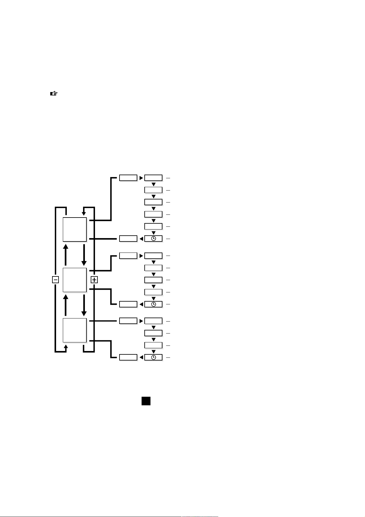
MODE functions with WATT
When the display shows the power function (WATT), other functions are available with the
MODE key. The stop watch (ETM) continues to run. When you are in WATT mode, TRP,
MAX and AVS refer to trip use, maximum and average power, respectively.
The term trip use requires some explanation. Before being reset or turned off, the computer
uses the stop watch and delivered power to calculate the trip use in kilocalories (Kcal).
MODE functions with CAD
When the display is in the pedalling frequency mode (CAD), TRP, MAX and AVS refer to the
total number of pedal revolutions during the trip, maximum and average pedalling frequency,
respectively.
By experimenting with the + or - key of MODE, you can combine various data. Pressing the
key once produces data quickly and accurately. In this way, you will soon get used to the
computer. Within ten minutes, you will be able to locate combinations that you will find
interesting or important.
Using the computer
47
KM/h
WATT
CAD
MODE ETM
TRP
ODO
MAX
AVS
MODE
MODE
MODE
MODE
MODE
ETM
TRP
MAX
AVS
TRP
MAX
AVS
Stopwatch
Cycling distance
Total distance
Maximum speed
Average speed
Stopwatch
Trip use in Kcal
Maximum power
Average power
Total pedal revolutions per trip
Maximum pedalling frequency
Average pedalling frequency
Clock
Clock
Clock
GB
Page 48

Using the computer
48
WATT MAX
SLOPE KM/h
WATT
SLOPE KM/h
MAX
18
19
Slope (SET-function)
Now we will go a step further. The Basic also enables you to
simulate resistance artificially. The Basic does this with SLOPE,
the slope resistance factor. This resistance factor comes from the
trainer's roller. The faster the roller turns, the easier it is for the
computer to apply the brakes to the roller. At low speeds and
low pedalling frequencies, it is more difficult for the Basic to
brake the roller than it is at high speeds and high pedalling frequencies. For this reason, we have programmed fourteen steps in
the SLOPE, from -4 to and including +9. The slope resistance
factor for values exceeding nil depends on body weight.
By pressing the SET key, the slope resistance mode (SLOPE) will
flash in the lower left-hand corner of the display (fig. 18). The
default setting is 0. Using the + and - key, you can vary the slope
resistance factor from -4 to and including +9 (fig. 19).
By pressing the MODE key, you can then set a new slope
resistance factor.
You might think that a slope resistance factor of +9 equals a
slope angle of +9 degrees and a slope resistance factor of -4,
with a slope angle of -4 degrees. Obviously, with a slope
resistance factor of -4, the trainer will not descend if you stop
pedalling. The steps from -4 to +9 are used to enable the
trainer to make the proper resistance calculations and
adjustments for the programmed power.
Programmed Power (SET-function)
Finally, you can go a step further. After pressing the SET key,
while the slope resistance mode is flashing (fig. 20), by pressing
SET again the programmed power (WATT prg) will start to flash
in the upper left-hand corner of the display (fig. 21). With programmed power, independent of pedalling speed and pedalling
frequency, the computer attempts to adjust the resistance on the
roller so that you are constantly producing the pedalling power
you wanted and which you programmed. When you change
pedalling frequency, the computer automatically adjusts the
resistance on the roller, so you constantly produce the same
power. If you change your own resistance, the computer follows
suit, adjusting the resistance on the roller.
You can set the programmed power using the + and - key, in
stages of 10 watts (fig. 22), when the WATT prg is flashing. The
standard programmed power is 100 watts, but you can adjust it
from 0 watts to and including 990 watts. Most cyclists, however,
prefer to train with values between 100 and 400 watts.
WATT
SLOPE KM/h
KG
MAX
WATT PRG
KM/h
MAX
20
21
GB
Page 49

Using the computer
49
After setting the programmed power, you can enter it by pressing the MODE key (fig. 23). Once the programmed power has
been entered, the SLOPE value disappears as long as you are
cycling in the WATT prg mode. The computer keeps track of the
most recently programmed power, even after it has been turned
off. To exit from the programmed power, you should press the
SET key twice, which will put you back in the SLOPE mode.
Power (Watt) equals Effort times Speed
During cycling, the Basic will use SLOPE to adjust the power
(watts) you programmed. Suppose, for example, you have
programmed a power of 400 watts and you want to pedal this
relatively high power, using relatively little effort (e.g. resistance
39 x 26) and a relatively low speed (e.g. a pedalling frequency of
70). The SLOPE cannot provide sufficient resistance to attain the
programmed power. You will see that the WATT designation at
the bottom right (actual power) does not agree with the
programmed power (WATT prg).
WATT prg will start to flash at the upper left of the display
(fig. 24) to indicate that you are outside the computer's field of
operation. By adjusting your resistance (greater/heavier) and
pedalling frequency (higher), you will soon find yourself returning
to the computer's field of operation. WATT prg will then light up
continuously.
Conversely, if you have programmed relatively low power and
you attempt to attain it with relatively great effort (e.g. resistance
52 x 16) and a high speed (e.g. pedalling frequency of 100), the
actual power will logically extend beyond the programmed
power. Here, too, you will be outside the computer's field of
operation, with WATT prg flashing in the upper left corner.
Adjust acceleration and pedalling frequency until you reenter the
computer's field of operation.
WATT pr g
KM/h
MAX
24
WATT pr g
KM/h
MAX
WATT pr g
KM/h
MAX
22
23
GB
Page 50

Training recommendations
50
4 TRAINING RECOMMENDATIONS
Of all sports requiring a major physical effort from the athlete, cycling heads the list. Cycling is
generally seen as the most physically difficult sport in terms of the pressure that heart, lungs
and muscles are subjected to. For those using the Tacx Cycletrainers, the same holds true to a
certain degree, especially since you want to increase the pressures you undergo. An extensive,
annual medical checkup with a professional sports doctor is the first requirement before you
start a new cycling season.
A possible definition of training could be “The systematic application of stimuli to improve
performance”. We have a goal when we train. The goal could be to lose weight, to complete
a particular sporting cycle on the bike or to win a gold medal during a championship race.
The “stimuli” that we apply could consist of riding long distances at a steady pace, or sprinting
short distances. It is important to build up the intensity of the training. As the season progresses,
we ride longer, further or even cycle at altitude (in the mountains). When it comes to real
improvement of performance, variation is the magic word.
Super Compensation
When we train, we cause a disruption in the body. This disruption (of heart, lungs, muscles)
recovers when we rest and improves slightly. We call this principle super compensation. It is not
the training that makes us stronger; it is the rest period that follows. The subsequent training
should take place just before the super compensation curve reaches the zero line (fig. 25). To
raise one's physical fitness to a higher level, it is necessary to train a minimum of three times a
week. Training twice a week is sufficient to retain one's physical fitness. Once a week is not
enough. You can devise your own training schedule or have your coach or trainer do so.
During training with the Basic, it would be
advisable to use a pulse meter.
Examples of Training Programmes
Always do warming-up exercises before you
start training. Five or ten minutes of relaxed
cycling with little resistance and a pedal
frequency of between 90 and 110 revolutions
per minute. During the warming-up period,
you can do some stretching exercises
(even on the bike). End the training with
a cooling-down period of between five and
ten minutes, again followed by some
stretching exercises. Avoiding warming-up
and cooling-down sessions could lead to injuries.
The Tacx Basic is very well equipped for specific training. Befor starting the trainingsprogramm
it would be wise to test your physical health so that you know what power you can apply and
what heartrates you have. Than prepare, e.g. with a trainer/coach, an annual training plan
(year, month and week plan) set for your own goals, levels and possibilities. During the annual
plan you train on the Basic throughout the seasons (so not only with bad weather). Power
training makes you stronger, faster and better. You climb, sprint, work with a powertraining
(see example) and simulate a time trial.
With the Basic it is also possible to do a “Conconi test”, the Astrandtest or the PWC test
(Physical Work Capacity). The last two tests are available on our website. You will be able to
ride them right after you have entered your personal data and you will see the results of the
tests right away.
Training advice and the latest developments at the Tacx homepage: www.tacx.nl.
25
0
Training
work
Recovery
Super
com
pen
sation
GB
Page 51

Training recommendations
51
GB
Recovery work-out
Time(min) Slope rpm Gear Details
3 1 100 lowest relaxed pedalling/high speed
3 1 100 1 heavier relaxed pedalling/high speed
3 1 100 1 heavier relaxed pedalling/high speed
3 1 100 1 heavier relaxed pedalling/high speed
3 1 100 1 heavier relaxed pedalling/high speed
3 1 100 1 heavier relaxed pedalling/high speed
3 1 100 1 lighter relaxed pedalling/high speed
3 1 100 1 lighter relaxed pedalling/high speed
3 1 100 1 lighter relaxed pedalling/high speed
3 1 100 1 lighter relaxed pedalling/high speed
3 1 100 1 lighter relaxed pedalling/high speed
3 1 100 lowest relaxed pedalling/high speed
36
You might want to repeat this again on position 2 in 2 minutes each time and again on position 3
with 1 minute repeaters. For variation you could ride with pedal frequency 80, 90, 110 or 120.
Power work-out
Time(min) Watt rpm Gear Details
3 80 80/90 free warming-up/relaxes pedalling
4 140 100 lowest increase speed
3 180 100 lowest increase speed
2 200 100 lowest increase speed again
1 240 90 lowest increase speed even more
3 80 120 lowest relaxed pedalling
4 180 60 heavy low speed/ remain seated
3 200 70 heavier low speed/ remain seated
2 220 80 heavier low speed/ remain seated
1 260 70 heavier stand on pedals
5 80 80/90 free cooling-down
31
The power used in these kinds of training is easily adapted to the individual demands/skills of the
rider. Do not start on a level that is too high for you and make sure you finish the ride. Only than
will training be effective!!
Hill work-out
Time(min) Slope rpm Gear Details
4 2 80/90 free relaxed pedalling/constant speed
3 3 > 80 free try to keep speed high
1 7 60 53-14 stand on pedals!
5 1 > 100 42-16 high pedal frequency
2 5 > 80 53-15 sit/stand every 30"
2 6 90/100 42-16 remain seated
5 1 110/130 42-16 high pedal frequency
10
1 free free cooling-down
32
Page 52

Error messages
52
Potential problem
1 The CycleForce frame is not
level
2 The frame has not been
assembled properly
3 The bike does not fit
properly in the frame
4 The frame is not fully
extended
1 The tyre pressure is too low
2 The roller does not press
properly against the tyre
1 A profile tyre was installed
2 There is a pebble (ticking) in
the tyre
1 The ambient temperature is
too low or too high
2 The display does not have a
good angle of view
3 The computer is not properly
connected to the mag unit
4 Perspiration may have dama-
ged the computer print plate
5 The print plate of the mag
unit is burned out
1 There is an interruption in
Basic while saving the values,
for example, due to a power
failure during training
Solution
1 Place the trainer on a level floor
2 Check whether all bolts and nuts are
properly tightened
3 Check whether the Tacx Quick-release
skewer has been mounted
4 Unfold frame completely
1 Check tyre pressure, minimal
6 atmosphere
2 Turn role so that it presses solidly
against the tyre
1 Mount tyre with totally or partially
smooth tyre profile
2 Check tyre for damage
1 Use Excel at ambient temperatures
between 5º C and 35º C (40ºF & 95º)
2 Adjust the display so that you can look
directly at it
3 Check the cable and the plug contacts
in the computer and the mag unit.
They could be dirty, oxidised or bent
4 The print plate should be replaced
5 The print plate should be replaced
1 To reset the computer completely:
Depress the SET key for five seconds
while inserting the plug at the bottom
of the computer. Then press the
MODE key twice
Failure
1 The arrangement of
the Basic when the
bike wobbles
2 Rubber from the
bike tyre sticks to
the roller
3 The bike makes a
lot of noise
4 Display is difficult to
read or illegible
5 The display shows
incorrect values
5 ERROR MESSAGES
Trainer
Basic computer and mag unit
GB
Page 53

Error messages
53
Solution
1 Check the cable and plug contacts in
the computer and the mag unit. They
could be dirty, oxidised or bent
2 The Basic works properly between
220 and 230 V/50Hz.
3 The lid of the mag unit should be
replaced
4 The print plate should be replaced
1 Replace the chain
2 Make sure the rear tyre pressure is
good
3 The mag unit will be warm after about
three minutes of cycling
4 Usethe Basic at ambient temperatures
between 5º C and 35º C (40ºF & 95º)
1 Connect the sensor or install a good
magnet
2 Make sure, the distance between the
sensor and the magnet is about 3 mm
3 Connect a new sensor
4 Check whether the plug is completely
in the connection
1 Check the cable and the plug contacts
in the computer and the unit. They
could be dirty, oxidised or bent
2 Adjust the mag unit with the adjust-
ment knob, so that the tyres cannot
slip
3 A new print plate will have to be
installed in the magnet unit
Potential problem
1 The mag unit does not brake
properly or at all
2 The mains voltage is too low
3 Several magnets of the mag
unit are loose due to having
been dropped
4 The print plate of the mag
unit is burned out
1 The bike chain is worn
2 Tyre pressure is too low
3 The mag unit is not yet warm
4 The ambient temperature is
too low
1 The cadence sensor has not
been connected or the
magnet has fallen out of the
magnet holder
2 The sensor was installed out
of range of the magnet
3 There is a break in the
cadence sensor cable
4 The sensor plug is not con-
nected properly to the mag
unit
1 The speed impulses do not
reach the computer
2 The bike wheel does not
reach the mag unit roller
3 The speed sensor in the mag
unit is defective
Failure
6 Cycling power
seems less than
shown on the display
7 Cycling power
seems higher than
shown on the display
8 The pedalling
frequency remains
zero
9 The cycle speed
remains zero
GB
Page 54

EU DECLARATION OF CONFORMITY
In accordance with the EU Machinery Directive 93/68EU Appendix II A.
We, Technische Industrie Tacx BV, Rijksstraatweg 52, 2241 BW Wassenaar the Netherlands
hereby declare that the machine described below both in its excel design and construction and
in the version marketed by us conforms to the relevent safety- and health-related requirements
of the appropriate EU Directive. This declaration shall cease to be valid if modifications are
made to the machine without our approval.
Product: CycleForce
Type: Basic
Technical Data: 220 V AC 50 Hz
Applicable EU Directives:
EU Machinery Directive (89/392/EU), in version 93/68/EU - EU Low-Voltage Equipment
Directive (73/23/EU) - EU Directive on Electromagnetic Compatibility (89/336/EU), in
version 93/31/EU.
Harmonised standards applied:
EN 50081-1: EN 55022 (1993) class B, EN 50082-1: EN 61000-4-2; EN 61000-4-3; EN 610004-4; EN 61000-4-5 and EN 61000-4-6
It is ensured through internal measures that series-production units conform at all times to the
requirements of current EU Directives and relevant standards.
Wassenaar, 23-09-2000
J.H.J. Tacx
Speed (Km/h or Mi/h)
Current speed
Kilometer or Miles per hour
0,1 to 99,9 Km/h or Mi/h
Stopwatch, cycling time
Capacity 8 hours, 59 minutes, 59 seconds
TRP trip distance
Capacity 999,9 Km or Mi
ODO total distance
Capacity 99.999,9 Km or Mi
MAX maximum speed
Capacity 99,9 Km or Mi per hour
AVS average speed
Capacity 99,9 Km or Mi per hour
Power (watt)
Current power
Capacity 2-999 watt
AVS average power
Capacity 999 watt
MAX maximum power
Capacity 999 watt
TRP trip use in Kcal
Capacity 999,9 Kcal
Technical specifications & EU Declaration of Conformity
54
6 TECHNICAL SPECIFICATIONS
Pedalling frequency (cad)
Current pedalling frequency (cadence)
Capacity 0-250 pedal revolutions
per minute
AVS average pedalling frequency
Capacity 250 pedal revolutions per minute
MAX maximum pedalling frequency
Capacity 250 pedal revolutions per minute
TRP Pedal revolutions per trip
Capacity 99.999 pedal revolutions
Various
24-hour clock
Capacity 23 hours, 59 minutes and
59 seconds
SLOPE resistance
-4 to +9 in increments of 1
WATT, modifiable power
0-990 Watt in increments of 10
Temperature Range
5º C to 35º C (40ºF to 95º)
GB
Page 55

Warranty provisions
55
7 WARRANTY PROVISIONS
Tacx products are manufactured in accordance with the highest quality standards. A warranty
period of one (1) year from the date of purchase applies to manufacturing or material defects
of all Tacx products. Save the sales slip, since that is your proof of purchase!
The warranty shall expire if the product shows clear evidence of the following:
1 use for any purpose other than that for which it was intended
2 inexpert use, repairs or dismantling
3 damage due to accidents or neglect
4 damage to the computer's printer plate caused by perspiration and/or humidity
5 defects that occur during shipment or transport of the product
The warranty does not apply to parts subject to normal wear and tear (e.g. batteries).
Shipping Costs
- Shipping charges to a Tacx dealer or Tacx Service Centre are for the owner's account.
- Tacx Service Centre will carry out repairs and provide return shipping without charge.
Procedure
- If, during normal use, a product does not function properly for any reason whatsoever, return it
to your dealer, along with proof of purchase (copy of the sales slip) and a completed service
form. You can also ship it directly to the nearest Tacx Service Centre in your country. There is a
list of Tacx Service Centres in the Tacx catalogue, the user's manual and at the Tacx web site.
- Follow the instructions for return shipments. The Tacx Service Centre will only accept return
shipments accompanied with completed service forms.
- The Tacx Service Centre will repair or replace products covered by the warranty within 30
days, free of charge.
- Technische Industrie Tacx bv shall be the sole judge as to whether a product is covered by the
warranty. If a product is not covered by the warranty, it will be repaired and the charges will be
billed. If the cost of repair exceeds 50.00 Euro, you will receive a cost estimate in advance.
After receiving your confirmation, the product will either be repaired or returned to you in
its original state.
Instructions for return shipments
1 Only send those parts of the Tacx product that require repair.
2 Repack everything carefully in the original packaging. Transport damage will be for your account.
3 Fill in the service form completely and clearly.
4 Include a copy of the sales slip.
5 Send the package prepaid - with optional insurance - to the Tacx Service Centre in your country.
Liability
- Technische Industrie Tacx bv reserves the right to modify, improve or to cease manufacturing
any of its products without prior notification.
- Tacx bv shall not be obligated to add new features or elements to previously sold products,
even if said products are returned under cover of warranty.
- Tacx bv may replace defective parts by equivalent parts of similar quality, if identical parts
are not available.
- Tacx bv will not accept liability whatsoever for direct, incidental or particular damages arising
from or relating to the use of the products.
GB
Page 56

56
Service Form
SERVICE FORM
Before shipping the product for repair, read the error messages in the accompanying user's
manual and go through the FAQs on the web site. To be eligible for service, use this form and
fill in all information clearly.
Name, Initials . . . . . . . . . . . . . . . . . . . . . . . . . . . . . . . . . . . . . . . . . . . . . . . . . . . . . . . . . . . . . . . . . . . . . . . . . . . . . . . . . . . . . . . . . . . . . . . . . . . . . . . . . . . . . . . . . . . . . . . . . . . . . . . . . . . . . . . . . . . . . . . . . .
Address . . . . . . . . . . . . . . . . . . . . . . . . . . . . . . . . . . . . . . . . . . . . . . . . . . . . . . . . . . . . . . . . . . . . . . . . . . . . . . . . . . . . . . . . . . . . . . . . . . . . . . . . . . . . . . . . . . . . . . . . . . . . . . . . . . . . . . . . . . . . . . . . . . . . . . . . . . . .
Postal Code . . . . . . . . . . . . . . . . . . . . . . . . . . . . . . . . . . . . . . . . . . . . . . . . . . . . . . . . . . . . . . . . . . . . . . . . . . . . . . . . . . . . . . . . . . . . . . . . . . . . . . . . . . . . . . . . . . . . . . . . . . . . . . . . . . . . . . . . . . . . . . . . . . . .
To w n . . . . . . . . . . . . . . . . . . . . . . . . . . . . . . . . . . . . . . . . . . . . . . . . . . . . . . . . . . . . . . . . . . . . . . . . . . . . . . . . . . . . . . . . . . . . . . . . . . . . . . . . . . . . . . . . . . . . . . . . . . . . . . . . . . . . . . . . . . . . . . . . . . . . . . . . . . . . . . . .
Country . . . . . . . . . . . . . . . . . . . . . . . . . . . . . . . . . . . . . . . . . . . . . . . . . . . . . . . . . . . . . . . . . . . . . . . . . . . . . . . . . . . . . . . . . . . . . . . . . . . . . . . . . . . . . . . . . . . . . . . . . . . . . . . . . . . . . . . . . . . . . . . . . . . . . . . . . .
Telephone . . . . . . . . . . . . . . . . . . . . . . . . . . . . . . . . . . . . . . . . . . . . . . . . . . . . . . . . . . . . . . . . . . . . . . . . . . . . . . . . . . . . . . . . . . . . . . . . . . . . . . . . . . . . . . . . . . . . . . . . . . . . . . . . . . . . . . . . . . . . . . . . . . . . . . . .
Product: Tacx Basic
Date of Purchase............................................................................................................................
Computer Serial Number . . . . . . . . . . . . . . . . . . . . . . . . . . . . . . . . . . . . . . . . . . . . . . . . . . . . . . . . . . . . . . . . . . . . . . . . . . . . . . . . . . . . . . . . . . . . . . . . . . . . . . . . . . . . . . . . . . . . . . . . . . . .
Receipt of Purchase (copy enclosed)?
Warranty Expired?
yes no
yes no
Description of complaint: . . . . . . . . . . . . . . . . . . . . . . . . . . . . . . . . . . . . . . . . . . . . . . . . . . . . . . . . . . . . . . . . . . . . . . . . . . . . . . . . . . . . . . . . . . . . . . . . . . . . . . . . . . . . . . . . . . . . . . . . . . . . .
. . . . . . . . . . . . . . . . . . . . . . . . . . . . . . . . . . . . . . . . . . . . . . . . . . . . . . . . . . . . . . . . . . . . . . . . . . . . . . . . . . . . . . . . . . . . . . . . . . . . . . . . . . . . . . . . . . . . . . . . . . . . . . . . . . . . . . . . . . . . . . . . . . . . . . . . . . . . . . . . . . . . . . . . . .
. . . . . . . . . . . . . . . . . . . . . . . . . . . . . . . . . . . . . . . . . . . . . . . . . . . . . . . . . . . . . . . . . . . . . . . . . . . . . . . . . . . . . . . . . . . . . . . . . . . . . . . . . . . . . . . . . . . . . . . . . . . . . . . . . . . . . . . . . . . . . . . . . . . . . . . . . . . . . . . . . . . . . . . . . .
. . . . . . . . . . . . . . . . . . . . . . . . . . . . . . . . . . . . . . . . . . . . . . . . . . . . . . . . . . . . . . . . . . . . . . . . . . . . . . . . . . . . . . . . . . . . . . . . . . . . . . . . . . . . . . . . . . . . . . . . . . . . . . . . . . . . . . . . . . . . . . . . . . . . . . . . . . . . . . . . . . . . . . . . . .
. . . . . . . . . . . . . . . . . . . . . . . . . . . . . . . . . . . . . . . . . . . . . . . . . . . . . . . . . . . . . . . . . . . . . . . . . . . . . . . . . . . . . . . . . . . . . . . . . . . . . . . . . . . . . . . . . . . . . . . . . . . . . . . . . . . . . . . . . . . . . . . . . . . . . . . . . . . . . . . . . . . . . . . . . .
Other information for Tacx Service Centre . . . . . . . . . . . . . . . . . . . . . . . . . . . . . . . . . . . . . . . . . . . . . . . . . . . . . . . . . . . . . . . . . . . . . . . . . . . . . . . . . . . . . . . . . . . . .
. . . . . . . . . . . . . . . . . . . . . . . . . . . . . . . . . . . . . . . . . . . . . . . . . . . . . . . . . . . . . . . . . . . . . . . . . . . . . . . . . . . . . . . . . . . . . . . . . . . . . . . . . . . . . . . . . . . . . . . . . . . . . . . . . . . . . . . . . . . . . . . . . . . . . . . . . . . . . . . . . . . . . . . . . .
. . . . . . . . . . . . . . . . . . . . . . . . . . . . . . . . . . . . . . . . . . . . . . . . . . . . . . . . . . . . . . . . . . . . . . . . . . . . . . . . . . . . . . . . . . . . . . . . . . . . . . . . . . . . . . . . . . . . . . . . . . . . . . . . . . . . . . . . . . . . . . . . . . . . . . . . . . . . . . . . . . . . . . . . . .
. . . . . . . . . . . . . . . . . . . . . . . . . . . . . . . . . . . . . . . . . . . . . . . . . . . . . . . . . . . . . . . . . . . . . . . . . . . . . . . . . . . . . . . . . . . . . . . . . . . . . . . . . . . . . . . . . . . . . . . . . . . . . . . . . . . . . . . . . . . . . . . . . . . . . . . . . . . . . . . . . . . . . . . . . .
. . . . . . . . . . . . . . . . . . . . . . . . . . . . . . . . . . . . . . . . . . . . . . . . . . . . . . . . . . . . . . . . . . . . . . . . . . . . . . . . . . . . . . . . . . . . . . . . . . . . . . . . . . . . . . . . . . . . . . . . . . . . . . . . . . . . . . . . . . . . . . . . . . . . . . . . . . . . . . . . . . . . . . . . . .
. . . . . . . . . . . . . . . . . . . . . . . . . . . . . . . . . . . . . . . . . . . . . . . . . . . . . . . . . . . . . . . . . . . . . . . . . . . . . . . . . . . . . . . . . . . . . . . . . . . . . . . . . . . . . . . . . . . . . . . . . . . . . . . . . . . . . . . . . . . . . . . . . . . . . . . . . . . . . . . . . . . . . . . . . .
. . . . . . . . . . . . . . . . . . . . . . . . . . . . . . . . . . . . . . . . . . . . . . . . . . . . . . . . . . . . . . . . . . . . . . . . . . . . . . . . . . . . . . . . . . . . . . . . . . . . . . . . . . . . . . . . . . . . . . . . . . . . . . . . . . . . . . . . . . . . . . . . . . . . . . . . . . . . . . . . . . . . . . . . . .
GB57F
Page 57

Contenu de l’emballage
Vérifiez si tous les accessoires suivants
figurent bien dans l’emballage
- Basic computer
- Entraîneur Tacx CycleForce
- rouleau de résistance
- Set de câbles
- Manuel
T1424.01
2x
T1424.02
2x
T1465.012xT1465.08
2x
T1402
1x
T1408.11
1x
T1410.021xT1410.04
2x
T1410.06
1x
T1423.15
2x
T1424.03
2x
T1461.19
2x
T1615.18
1x
T1466.01
1x
T1466.021xT1466.03
1x
T1466.04
1x
T1260.074xT1461.19
4x
T2459.03
4x
- T1466 Sachet de montage set d’adaptation unité
- T1615 Sachet de montage entraîneur
- Pieds et embouts
Page 58

58
INDEX
1 Montage Basic
Montage du simulateur 59
Branchement de l’ordinateur Basic 61
2 Réglage unique de l’ordinateur de bord
Réglage de l’indication de vitesse (Km/h ou Mi/h) 62
Réglage du poids corporel 62
Réglage de l’horloge 24 heures 62
3 Utilisation de l’ordinateur de bord
Fonctions MODE en Km/h (ou Mi/h) 63
Réinitialisation des functions sous la touche MODE 64
Fonctions sous la touche + et - 64
Fonctions MODE sous WATT 65
Fonctions MODE sous CAD 65
Fonction SET sous Slope 66
Fonction SET sous WATT prg (Puissance programmée) 66
Puissance (watts) = Force x Vitesse 67
4 Conseils pour l’entrainement
Super-compensation 68
Exemples de programmes d'entraînements 68
5 Disfonctionnements 70
6 Spécifications techniques &
Déclaration de conformité CE 72
7 Dispositions de garantie
Procédure 73
Instructions pour réexpédition 73
Carte de service 74
Lexique des symbôles
Indique un sujet important. Donc: attention!
Indique un conseil important. Bon à savoir.
Index
F
Page 59

Montage Basic
59
F
1 MONTAGE BASIC
Le Basic est constitué d’un cadre pliable sur lequel votre vélo vient se fixer (le CycleForce est
adaptable de série aussi bien aux vélos de course qu’aux VTT et modèles hybrides au diamètre
de roue de 630 à 690 mm) et un ordinateur Basic.
Montage du simulateur
Le montage et le réglage du simulateur sont à effectuer une fois pour toutes
selon les instructions suivantes:
1 Enfoncer l’écrou A dans l’embout B et glisser l’embout dans le tube du
cadre (fig. 1).
2 Fixer le pied C au cadre à l’aide du boulon D. Serrer le boulon D de telle
manière que le pied reste réglable.
3 Placer le cadre déplié sur une base solide et plane. Le cadre se plie et se déplie
en serrant à fond la poignée E (fig. 1).
4 Placer le pied C en position adéquate (fig. 2). Bien serrer le boulon D et fixer le caoutchouc
anti-dérapant F (fig. 4).
5 Monter les bagues en caoutchouc G et la douille K sur le levier H (fig.3). Fixer ensuite l’ensemble
du levier au cadre. Adapter le rouleau de résistance I à la douille K du levier et tourner le boulon J de telle sorte que l’unité puisse rester mobile (fig. 4).
6 Remplacer le blocage rapide de la roue arrière par le blocage Tacx X fourni pour obtenir une
stabilité et un calage parfaits. Positionner ensuite le vélo sur le rouleau et régler l’écrou papillon
L de l’appareil de façon à pouvoir fermer le blocage rapide M sans forcer. Un serrage excessif
peut occasionner des dégâts!
7 Fixer l’écrou-papillon L en serrant la vis-papillon N.
E
A
D
C
B
C
1
2
10 mm
13 mm (2x)13
mm (2x)
J
LN
X
M
E
I
K
H
F
4
H
K
G
3
Page 60

60
Montage Basic
F
8 Le levier H permet d’amener ou d’éloigner le volant d’inertie sur le pneu du vélo (fig. 5 et 6).
Lorsque le levier H est en position de contact, on peut relâcher la pression du rouleau sur le
pneu à l’aide du patin R. Veiller à ce que le rouleau soit bien au contact du pneu afin d’éviter les
effets de patinage en cours d’utilisation.
Montage modifié pour vélos à diamètre de roues différent
Avant que le levier complet soit fixé au cadre, se référer au point 5 des instructions
concernant les plaquettes de rehaussement ou de rallongement.
Diamètre de roue de 610 à 640 mm: utiliser les plaquettes de rehaussement W à quatre
boulons, écrous et bagues (fig. 7).
Diamètre de roue de 690 à 720 mm: utiliser les plaquettes de rallongement Z (fig. 8).
Conseils
- Avant d’utiliser le CycleForce ou après avoir déplié le cadre, vérifier la bonne position de la
poignée E afin d’éviter toute dégradation au niveau du cadre.
- Lors du montage, veiller à ce que le simulateur de résistance ne s’affaisse pas. Cela pourrait
entraîner un déséquilibre au niveau de l’axe et provoquer des vibrations.
- S’assurer que le pneu est bien gonflé (6 atm. minimum, 4 s’il s’agit d’un VTT).
- Pour les VTT, il est préférable d’utiliser un profil de pneu entièrement ou partiellement lisse,
une forte sculpture entraînant des effets de bruit et de patinage.
- Eviter de freiner brutalement durant une séance d’entraînement sur le CycleForce. En cas de
freinage sur la roue arrière, le volant d’inertie continue de tourner, soumettant le pneu à une
usure inutile.
- Contrôler régulièrement le serrage des vis et écrous du simulateur.
- Des tests ont démontré que le rouleau-résistance n’éprouvait aucune surchauffe en performances extrêmes. Par contre, soumis à une utilisation intensive de longue durée, la carcasse de
l’unité peut devenir assez chaude. Il est donc conseillé de la laisser refroidir quelques instants
après chaque utilisation avant de s’en saisir.
H
R
H
5 6
W
W
H
Z
Z
H
7 8
Page 61

61
Montage Basic
Branchement de l’ordinateur Basic
Après avoir positionné le vélo sur le CycleForce, brancher l’ordinateur Basic comme suit:
1 Monter l’ordinateur Basic sur le guidon à l’aide des deux colliers de serrage en caoutchouc P
(fig. 4).
2 Raccorder l’ordinateur au simulateur de résistance à l’aide du câble Q, en veillant bien à ce que
le câble ne puisse être arraché par la chaussure ou la pédale pendant l’entraînement.
3 Placer le petit aimant de cadence R sur la face intérieure de la manivelle gauche (fig. 5).
4 Fixer le capteur de cadence S sur la face intérieure du fourreau de fourche arrière gauche.
Le capteur doit se trouver à hauteur de l’aimant, à environ 3 mm d’écart. Raccorder le câble du
capteur au simulateur de résistance en veillant bien, là aussi, à ce qu’il ne rencontre pas
d’obstacle et ne touche pas la roue.
5 Mettre la fiche dans la prise. Contrôler la réception du capteur de cadence en pédalant en
arrière. Le mot CAD apparaît dès lors sur l’écran. Le Basic est à présent prêt à l’emploi.
La transpiration et la condensation peuvent altérer les cristaux d’impression de l’ordinateur.
Ne pas utiliser le Basic dans des endroits humides, et sècher l’écran après usage en cas de besoin
afin d’éviter les détériorations. Une utilisation incorrecte et/ou un mauvais entretien entraînent la
suppression de la garantie.
5
P
P
4
F
S
R
R
S
Q
Page 62

Réglage unique de l'ordinateur de bord
62
Lorsque vous aurez introduit la fiche dans la prise, le cadran s'allumera un bref instant pour contrôle. Ensuite, vous passerez au
programme normal (fig. 6).
Vous pourriez commencer tout de suite, si vous n'aviez pas à
régler une fois pour toutes votre poids avant la première utilisation. A sa sort d'usin, l'ordinateur est réglé sur une indication de
vitesse en km/h et un poids de 75 kg. Si l'indication de vitesse
et le poids sont corrects, vous pourrez passer tout de suite au
programme normal.
Réglage de l'indication de vitesse
S'il faut changer le mode d'indication de la vitesse et/ou du poids,
maintenir pendant 6 secondes en même temps les touches SET
et MODE. Ensuite, le cadran fait apparaître SET UP (fig. 7). En
appuyant sur + ou- vous passerez de km/h (kilomètres à l'heure)
à Mi./h (milles anglais à l'heure) et inversement (fig. 8). Fixez
votre choix pour l'indication de vitesse en appuyant sur MODE.
Réglage du poids corporel
Ensuite apparaît le poids sur 75 kg (fig. 9). En appuyant sur
+ ou- vous réglerez votre poids par paliers de 1 kilo (fig. 10).
Pourque le compteur puisse calculer la puissance exacte fournie
pendant l'exercice, il est important de régler l'appareil sur le
poids correct. En effet, le calcul de la puissance tient compte de
votre poids. Le poids est réglable entre 40 et 120 kg.
Fixez ensuite votre poids en appuyant sur MODE. Lors d'une
prochaine utilisation, lorsque le compteur sera remis en marche,
celui-ci tiendra toujours compte du poids réglé en dernier lieu.
Bien entendu, il vous est toujours possible de changer le poids
par une nouveau réglage (SET UP), par exemple si vous invitiez
quelqu'un d'autre à s'entraîner sur le Basic.
Réglage de l'horloge 24 heures
Après avoir réglé le poids, vous pourrez éventuellement régler
l'horloge. Si vous ne souhaitez pas en faire usage, vous passerez
automatiquement au programme normal en appuyant 2 fois sur
la touche MODE. Dans ce cas, vous ne pourrez pas faire
apparaître l'heure pas pendant que vous pédalerez.
En revanche, si vous souhaitez faire usage de l'horloge 24 heures,
vous réglerez d'abord les heures avec la touche +/-. Ensuite,
vous presserez la touche MODE et la touche +/- vous permettra
de régler les minutes. Après avoir pressé encore une fois la touche MODE, vous en aurez terminé avec le réglage de l'horloge et
vous reviendrez dans le programme normal. Maintenant,
l'horloge apparaîtra, elle aussi, lorsque vous utiliserez les autres
fonctions. Lors de la mise à l'arrêt du compteur, l'horloge
s'arrêtera également.
Lorsque vous aurez besoin de l'horloge lors d'une autre séance,
il vous faudra la remettre à l'heure en effectuant une nouvelle
procédure de SET UP
KG
9
WATT ETM
SLOPE KM/h
KM/h
MI/h
6
7
8
F
2 RÉGLAGE UNIQUE DE L'ORDINATEUR DE BORD
Page 63

Utilisation de l'ordinateur de bord
63
KG
10
L'ordinateur une fois réglé, vous pouvez commencer à pédaler.
Vous pourrez exécuter toutes les opérations décrites ci-après
tout en pédalant sur le Basic, mais aussi à l'arrêt.
Le Basic enregistre 3 types de données. Le premier type a trait
à votre vitesse, ce que nous examinerons ci-après. Ensuite
traiterons des deux autres types (puissance et cadence).
Fonctions MODE en Km/h (ou Mi/h)
Sous la touche MODE se trouvent les fonctions "vélo" générales.
Chaque pression sur la touche MODE vous fait passer successivement dans les fonctions: ETM, TRP, ODO, MAX, AVS (voir
schéma fonctionnel). L'horloge 24 heures figure également
dans cette série, à condition de l'avoir réglée préalablement.
ETM (chronomètre)
Vous commencez en haut à droite par ETM, le chronomètre
(fig. 11). ETM est le temps où l'on pédale sans que le compteur
ne soit "réinitialisé" ou arrêté. Le chronomètre enregistre exclusivement le temps de pédalage. Vous pouvez donc intercaler une
pause, sans que cela influe sur le temps de pédalage effectif. Si
vous arrêtez le compteur ou que vous le réinitialisiez pendant
que vous pédalez, le chronomètre recommencera à zéro.
TRP (distance parcourue)
En appuyant encore une fois sur MODE, vous ferez apparaître
dans l'angle supérieur droit TRP, la distance parcourue (fig. 12).
La distance parcourue continue d'être calculée tant que le
compteur n'est pas réinitialisé ou arrêté.
ODO (distance totale)
Une nouvelle pression sur la touche MODE fera apparaître ODO
dans l'angle supérieur droit, la distance totale parcourue (fig. 13).
L'ODO totalise tous les trajets parcourus, son maximum étant
de 99.999 km (ou milles), après quoi il repart de zéro km.
ETM
chronomètre
TRP
distance
parcourve
ODO
distance
totale
MAX
vitesse
maximale
AVS
vitesse
moyenne
horloge
MODE
WATT TR P
SLOPE KM/h
WATT
SLOPE KM/h
WATT ODO
SLOPE KM/h
12
13
WATT ETM
SLOPE KM/h
11
F
3 UTILISATION DE L'ORDINATEUR DE BORD
Page 64

WATT MAX
SLOPE KM/h
14
Utilisation de l'ordinateur de bord
64
MAX (vitesse maximale)
Ensuite, à l'aide de la touche MODE, on fait apparaître MAX dans
l'angle supérieur droit (fig. 14). Il s'agit de la vitesse maximale
atteinte pendant la période où le compteur n'a été ni réinitialisé
ni mis à l'arrêt.
AVS (vitesse moyenne)
En pressant une dernière fois la touche MODE, vous ferez apparaître AVS dans l'angle supérieur droit, la vitesse moyenne. La
vitesse moyenne est calculée sur la période pendant laquelle le
compteur n'a été ni réinitialisé ni mis à l'arrêt.
HORLOGE
Si vous aviez choisi d'utiliser l'horloge, vous pourrez, après
l'AVS, en appuyant encore une fois sur la touche MODE, faire
apparaître l'horloge.
Réinitialisation des fonctions sous la touche MODE
Si, pendant un entraînement, vous souhaitez réinitialiser (remettre à zéro) des données stockées sous les rubriques ETM, TRP,
MAX et AVS, arrêtez-vous de pédaler, ramenez votre vitesse à 0
et appuyez en même temps sur les touches SET et MODE pendant 1 seconde (fig. 15). L'ODO n'est pas réinitialisable; en position kilométrique de 99.999 km, il se remet de lui-même à 0 km
(ou milles).
Fonctions sous la touche + et -
Comme on l'a vu plus haut, le Basic enregistre trois types de
données:
1 données ayant trait à votre vitesse (Km/h ou Mi/h).
2 données ayant trait à la puissance que vous fournissez (watts).
3 données ayant trait à votre cadence (CAD).
Avec les touches + et - vous pouvez faire commuter le visuel
de vitesse à puissance et de puissance à cadence, et ainsi de suite
(voir schéma fonctionnel).
WATT (puissance)
En actionnant la touche + vous commutez dans l'angle inférieur
droit de vitesse à WATT, la puissance fournie au moment même
(fig. 16).
CAD (cadence)
En actionnant à nouveau la touche + ou -, vous commuterez de
WATT à CAD, la cadence ou fréquence de pédalage actuelle
(fig. 17).
KM/h WATT CAD
-
+
WATT ET M
SLOPE KM/h
15
MAX
SLOPE WATT
16
WATT MAX
SLOPE CAD
17
F
Page 65

Fonctions MODE sous WATT
Lorsque le cadran affiche la puissance (WATT), vous pouvez également disposer des fonctions
regroupées sous la touche MODE. Le chronomètre (ETM) continue évidemment de tourner,
mais TRP, MAX et AVS signifient pendant l'indication WATT respectivement consommation en
cours de trajet, puissance maximale et puissance moyenne.
L'expression "consommation en cours de trajet" mérite une explication. Sans que le compteur
ait été réinitialisé ou mis à l'arrêt, le compteur calcule, sur la base du chronomètre et de la
puissance fournie, le nombre de kilocalories (Kcal) consommées en cours de trajet.
Fonctions MODE sous CAD
Lorsque le cadran affiche la cadence (CAD), TRP, MAX et AVS signifient respectivement nombre
total de tours de pédale pendant le trajet, cadence maximale et cadence moyenne.
En expérimentant à présent avec le bouton MODE et les touches + et-, vous pourrez combiner
des données diverses. Toute pression sur la touche fera apparaître les données rapidement et
avec précision. De cette manière, vous serez bientôt familiarisé avec l'ordinateur de bord. En
dix minutes vous saurez trouver les combinaisons qui vous conviennent le mieux ou que vous
jugez les plus importantes.
Utilisation de l'ordinateur de bord
65
KM/h
WATT
CAD
MODE ETM
TRP
ODO
MAX
AVS
MODE
MODE
MODE
MODE
MODE
ETM
TRP
MAX
AVS
TRP
MAX
AVS
Chronomètre
Distance parcourve
Distance totale
Vitesse maximale
Vitesse moyenne
Chronomètre
Consommation par trajet
Puissance maximale
Puissance moyenne
Tours de pèdalier
Cadence maximale
Cadence moyenne
Horloge
Horloge
Horloge
F
Page 66

Utilisation de l'ordinateur de bord
66
WATT MAX
SLOPE KM/h
WATT
SLOPE KM/h
MAX
18
19
Fonction SET sous SLOPE (résistance en montée)
Faisons un pas de plus. Avec le Basic, il vous est possible aussi de
simuler une résistance de manière artificielle. Cela se fait sur le
Basic au moyen de la résistance due à la montée (SLOPE). Cette
résistance agit sur le rouleau du simulateur. Ce faisant, il faut
savoir qu'à mesure où le rouleau tourne plus vite il est plus facile
pour le compteur de freiner le rouleau. A vitesse lente et faible
cadence, il est plus difficile pour le Basic de freiner le rouleau qu'à
une vitesse rapide et une cadence soutenue. C'est la raison pour
laquelle nous avons prévu quatorze paliers dans la résistance en
montée (SLOPE), allant de -4 à +9. La résistance en montée est
liée au poids pour les valeurs supérieures à 0.
Après avoir pressé la touche SET, vous verrez clignoter dans
l'angle inférieur gauche la résistance en montée (SLOPE), qui est
réglée d'usine sur 0 (fig. 18). Avec les touches + et -, vous
pouvez faire varier la résistance de -4 à +9 (fig. 19). En appuyant
ensuite sur la touche MODE, vous pourrez fixer le nouveau
paramètre de résistance.
Vous pourriez penser que la résistance en montée de +9
correspond à un angle d'inclinaison de +9' et une résistance en
montée de -4, à un angle d'inclinaison de -4'. Vous comprendrez que si vous gardez les jambes immobiles à une résistance
en montée de -4', le simulateur ne se mettra pas tout seul à
dévaler la pente. Les paliers de -4 à +9 s'utilisent pour
permettre au simulateur d'effectuer les calculs et adaptations
en résistance avec précision pour la puissance programmée.
Fonction SET sous WATT prg (Puissance programmée)
Enfin, vous pouvez faire encore un pas. Lorsqu'après avoir
actionné la touche SET et que clignote la résistance en montée
(fig. 20), vous appuyez encore une fois sur la touche SET, la
puissance programmée (WATT prg) se mettra à clignoter dans
l'angle supérieur gauche (fig. 21). En puissance programmée,
l'ordinateur essaiera, indépendam- ment du développement
sélectionné et indépendamment de la cadence, d'adapter la
résistance sur le rouleau de telle manière que vous obteniez
toujours constamment la puissance programmée et souhaitée
par vous. Si vous modifiez votre cadence, l'ordinateur adaptera
immédiatement la résistance sur le rouleau, grâce à quoi vous
continuerez de fournir constamment la même puissance. Si
vous changer la démultiplication, l'ordinateur fera exactement
la même chose: il adaptera la résistance sur le rouleau.
Il est possible de régler la puissance programmée avec les
touches+ et- par paliers de 10 watts (fig. 22) lorsque clignote
WATT prg. A sa sorti d'usin, la puissance programmée est
réglée sur 100 watts, mais vous pouvez la régler de 0 à 990
watts. La plupart des cyclistes s'entraîneront toutefois avec
des valeurs situées entre 100 et 400 watts.
WATT
SLOPE KM/h
KG
MAX
WATT PRG
KM/h
MAX
20
21
F
Page 67

Utilisation de l'ordinateur de bord
67
Après avoir réglé la puissance programmée, vous pourrez la fixer
en appuyant sur la touche MODE (fig. 23). Lorsqu'est stockée la
puissance programmée, l'indice SLOPE n'apparaîtra plus à l'écran
tant que vous roulerez en mode WATT prg.
L'ordinateur retient toujours la puissance programmée mise au
point en dernier lieu, même après arrêt de l'ordinateur. Pour sortir de la puissance programmée, vous devrez appuyer deux fois
sur la touche SET, ce qui vous fera passer en mode SLOPE.
Puissance (watts) = Force x Vitesse
Pendant que vous pédalez, le Basic adapte, au moyen du SLOPE,
la puissance que vous aurez programmée (watts). Supposons que
vous programmiez une puissance de 400 watts et que vous vouliez atteindre cette puissance relativement élevée avec une force
relativement faible (p.ex. un développement de 39 x 26) et une
vitesse relativement lente (p.ex. une cadence de 70). Le SLOPE
ne pourra pas générer une résistance suffisante pour atteindre la
puissance programmée. Vous verrez que l'indication WATT dans
l'angle inférieur gauche (la puissance actuelle) ne correspond pas
à la puissance programmée (WATT prg).
WATT prg se mettra à clignoter dans l'angle supérieur gauche
(fig. 24) pour indiquer que vous vous trouvez en dehors du
champ d'action de l'ordinateur. En adaptant votre démultiplication
(plus grande/plus dure) et votre cadence (plus rapide), vous vous
apercevrez automatiquement de l'instant où vous pénétrerez
dans le champ d'action de l'ordinateur. WATT prg s'allumera alors
en continu.
Inversement, si vous aviez programmé une puissance relativement faible et que vous essayiez d'y parvenir avec une force relativement grande (p.ex. un développement de 52 x 16) et une
vitesse rapide (p.ex. cadence 100), il est logique que la puissance
actuelle se situerait au-delà de la puissance programmée. Dans ce
cas aussi, vous seriez en dehors du champ d'action de l'ordinateur
et WATT prg clignoterait dans l'angle supérieur gauche. Adaptez
la démultiplication et la cadence de façon à vous retrouver dans
le champ d'action de l'ordinateur.
WATT pr g
KM/h
MAX
24
WATT pr g
KM/h
MAX
WATT pr g
KM/h
MAX
22
23
F
Page 68

Conseils pour l'entrainement
68
4 CONSEILS POUR L'ENTRAINEMENT
Il n'existe aucun sport requérant des efforts aussi durs et prolongés de la part du sportif que
dans le cyclisme. L'on considère généralement le cyclisme comme l'un des sports les plus durs
pour ce qui concerne la sollicitation du coeur, des poumons et des muscles. Pour la pratique des
Cycle Force Basic Tacx, il en va de même jusqu'à un certain point, d'autant plus que vous souhaitez amener ces sollicitations à un plus haut niveau. C'est la raison pour laquelle une visite
médicale approfondie pour sportifs auprès d'un spécialisé constitue un premier impératif, avant
d'attaquer une nouvelle saison cycliste.
On pourrait ainsi résumer la définition de l'entraînement: "La recherche systématique d'une
amélioration des performances". On s'entraîne toujours, en effet, dans un but précis: perdre du
poids, rouler plus vite qu'un collègue cyclo, ou décrocher la médaille d'or au championnat...
Autant d'objectifs divers tributaires de différentes manières de pratiquer le vélo. L'essentiel est
de respecter une systématisation dans la façon d'élaborer l'entraînement. Au fur et à mesure de
la saison, les sorties se font plus longues et plus sélectives. La variation est le point de passage
obligé d'une amélioration substantielle des performances.
Super-compensation
Au cours d'un entraînement, l'organisme est soumis à une perturbation (cardiaque, respiratoire,
musculaire), laquelle débouche sur une amélioration des potentialités en phase de repos: c'est
le principe de la super-compensation. Ce n'est donc pas l'entraînement en tant que tel qui rend
plus fort, mais le repos qui y fait suite. L'entraînement suivant doit donc intervenir au moment
précis où la courbe de super-compensation n'a pas encore tout à fait atteint le point zéro
(fig. 25). Pour améliorer sa condition physique, on estime que trois entraînements par semaine
au minimum sont nécessaires. Deux séances permettent de préserver la condition, une seule
séance s'avère insuffisante. A défaut de disposer d'un coach-entraîneur, vous pouvez donc
déterminer vous-même un schéma d'entraînement.
Exemples de programmes d'entraînements
Faites toujours précéder un entraînement d'une
séance d'échauffement: 5 à 10 minutes sur un
petit développement avec fréquence de pédalage
de 90 à 110 tours/minute. Durant cet
échauffement, on peut procéder à des étirements
(même sur le vélo). En fin d'entraînement,
respectez un temps de décompression
(cooling down) de 5 à 10 minutes également et
répétez les étirements. Une double précaution
destinée à éviter les blessures musculaires.
Le Tacx Basic est spécialement indiqué pour les
entraînements spécifiques. Avant d'entamer un
programme d'entraînement, il est recommandé
de procéder à un test de condition afin de déterminer la puissance qui peut être produite et les
rythmes cardiaques adéquats. Etablissez donc, éventuellement avec l'aide d'un coach-entraîneur,
un planning (annuel, mensuel et hebdomadaire) en fonction de vos objectifs, de votre niveau et
de vos potentialités. Dans le planning annuel, l'entraînement est programmé sur le Basic pour
toutes les saisons (et pas uniquement en cas de mauvaises conditions climatiques). l'entraînement en puissance vous rendra plus fort, plus rapide et plus performant. Vous apprendrez à
grimper, à sprinter, à finaliser un entraînement en force (voir exemple), et même à simuler un
contre-la-montre.
Avec le Basic, il est également possible de procéder à un test “Conconi”, un test Astrand ou un
test PWC (Physical Work Capacity). Ces deux derniers tests figurent sur le website Tacx, où
vous pouvez recevoir directement les résultats après avoir envoyé vos données.
Les conseils d'entraînement et les dernières évolutions: www.tacx.nl.
25
0
entraînement
récupération
super
compensation
F
Page 69

Conseils pour l'entrainement
69
Entraînement en récupération
temps (min) slope fréquence braquet description
3 1 100 petit vitesse élevée/tourner les jambes
3 1 100 1 supérieur vitesse élevée/tourner les jambes
3 1 100 1 supérieur vitesse élevée/tourner les jambes
3 1 100 1 supérieur vitesse élevée/tourner les jambes
3 1 100 1 supérieur vitesse élevée/tourner les jambes
3 1 100 1 supérieur vitesse élevée/tourner les jambes
3 1 100 1 inférieur vitesse élevée/tourner les jambes
3 1 100 1 inférieur vitesse élevée/tourner les jambes
3 1 100 1 inférieur vitesse élevée/tourner les jambes
3 1 100 1 inférieur vitesse élevée/tourner les jambes
3 1 100 1 inférieur vitesse élevée/tourner les jambes
3 1 100 petit vitesse élevée/tourner les jambes
36
Répétez éventuellement le programme en position 2 avec une périodicité de 2 minutes et en position
3 avec une périodicité de 1 minute. Vous pouvez également varier la fréquence de pédalage:
80, 90, 110 ou 120 tours/minute.
Entraînement en puissance
temps (min) watt fréquence braquet description
3 80 80/90 libre echauffement/sans forcer
4 140 100 petit augmenter la vitesse
3 180 100 petit augmenter la vitesse
2 200 100 petit vitesse supérieure
1 240 90 petit vitesse encore supérieure
3 80 120 petit pédaler sans forcer
4 180 60 gros basse vitesse/rester assis
3 200 70 plus gros basse vitesse/rester assis
2 220 80 plus gros basse vitesse/rester assis
1 260 70 plus gros debout sur les pédales
5 80 80/90 libre cool-down
31
Lors de cet entraînement, la puissance est facile à adapter au souhait et aux aptitudes du coureur.
Ne commencez pas avec une charge trop lourde et veillez à pouvoir finaliser la totalité de
l'entraînement afin qu'il soit véritablement efficace.
Entraînement en côte
temps (min) slope fréquence braquet description
4 2 80/90 au choix vitesse constante/tourner les jambes
3 3 > 80 au choix augmenter la vitesse
1 7 60 53-14 debout sur les pédales!
5 1 > 100 42-16 haute fréquence de pédalage
2 5 > 80 53-15 assis/debout: permutation toutes les 30”
2 6 90/100 42-16 position assise
5 1 110/130 42-16 haute fréquence de pédalage
10
1 au choix au choix cooling-down
32
F
Page 70

Disfonctionnements
70
Cause probable
1 le sol n'est pas plan
2 Mauvais montage du cadre
3 Le vélo n'est pas correcte-
ment monté sur le cadre
4 Le cadre n'est pas complète-
ment déplié
1 La pression du pneu est trop
faible
2 Le rouleau n'est pas bien au
contact du pneu
1 Profil du pneumatique
2 Présence d'un petit corps
étranger dans le pneu
1 Température ambiante trop
basse ou trop élevée
2 L'orientation de l'écran n'est
pas bonne
3 L'ordinateur est mal relié au
simulateur
4 De la sueur peut avoir
corrodé la platine du circuit
imprimé
5 La platine du volant magnéti-
que est grillée
1 Pendant l’enregistriment des
données, le Basic a été interrompu, p.ex. suite à une
coupure de courant en
cours d’entraînement
Solution
1 Placer l'entraîneur sur un sol plat
2 Vérifier que tous les boulons et
écrous sont bien serrés
3 Vérifier que le blocage rapide faisant
partie de la fourniture a été monté
4 Dépliez le simulateur entièrement
1 Contrôler la pression du pneu:
minimum 6 atm.
2 Serrer le rouleau fermement contre
le pneu
1 Monter en pneu à profil entièrement
ou partiellement lisse
2 Contrôler le pneu
1 Utiliser le Basic par température ambi-
ante entre 5ºC et 35ºC (40ºF et 95ºF)
2 Orienter l'écran de telle sorte qu'il
soit le plus perpendiculaire possible
au regard
3 Vérifier le câble et les contacts de la
fiche au niveau de l'ordinateur et du
simulateur. Ils peuvent être sales,
oxydés ou tordus
4 La platine doit être remplacée
5 La platine doit être remplacée
1 Réinitialisation complète du compteur:
maintenez pendant 5 secondes enfoncée, pendant que vous mettez la fishe
dans le bas du compteur, la touche
SET et pressez ensuite deux fois sur la
touche MODE
Avarie
1 L'entraîneur vacille
2 Des particules de
pneu restent collées
sur le rouleau
3 Fonctionnement
très bruyant lors
d'un entraînement
4 L'écran n'est pas
lisible
5 Valeurs erronés
sur le visuel
5 DISFONCTIONNEMENTS
Simulateur
Ordinateur Basic et simulateur de résistance
F
Page 71

Disfonctionnements
71
Solution
1 Contrôler le câble et les contacts de la
fiche au niveau de l'ordinateur et du
simulateur. Ils peuvent être sales, oxydés ou tordus
2 Le Basic fonctionne correctement
entre 220 et 230 V/50Hz.
3 Le couvercle du simulateur doit être
remplacé
4 La platine doit être remplacée
1 Remplacer la chaîne
2 Vérifier la pression du pneu arrière
3 Au bout de trois minutes environ,
l'unité atteint sa température de
fonctionnement
4 Utiliser le Basic par température
ambiante entre 5ºC/35ºC (40ºF/95ºF)
1 Brancher le capteur et installer un
aimant opérationnel
2 Vérifier que l'écart entre le capteur
et l'aimant soit d'environ 3 mm
3 Brancher un nouveau capteur
4 Contrôler si la fiche est bien complè-
tement introduite dans la prise
1 Vérifier le câble et les contacts de la
fiche au niveau de l'ordinateur et de
l'unité. Ils peuvent être sales, oxydés
ou tordus
2 Ajuster le bouton de réglage du volant
d'inertie afin d'éviter le patinage de la
roue
3 Faire installer une nouvelle platine
dans l'unité magnétique
Cause probable
1 Le simulateur ne freine pas
ou trop peu
2 La tension du réseau électri-
que est trop faible
3 Quelques aimants de l'unité
magnétique se sont détachés
à la suite d'un choc
4 La platine du simulateur est
grillée
1 La chaîne du vélo est usée
2 La pression des pneus est
insuffisante
3 Le volant d'inertie n'a pas
encore atteint sa bonne température
4 La température ambiante est
trop basse
1 Le capteur de cadence n'est
pas raccordé ou l'aimant est
tombé de son alvéole
2 Le capteur est hors de portée
de l'aimant
3 Rupture dans le câble du cap-
teur de cadence
4 La fiche du capteur n'est pas
correctement enfoncée dans
le raccord du volant d'inertie
1 Les impulsions de vitesse ne
parviennent pas à l'ordinateur
2 La roue n'est pas en contact
avec le volant d'inertie
3 Le capteur de vitesse, au
niveau du volant d'inertie,
est défectueux
Avarie
6 Vous éprouvez une
puissance développée plus basse que
celle affichée à
l'écran
7 Vous éprouvez une
puissance développée supérieure à
celle affichée à
l'écran
8 La cadence de péda-
lage reste au
niveau 0
9 La vitesse reste au
niveau 0
F
Page 72

DÉCLARATION DE CONFORMITÉ CE
Dans le sens de la directive européenne pour machines 93/68CE annexe II A.
Par la présente, laTechnische Industrie Tacx bv, Rijksstraatweg 52, 2241 BW Wassenaar
Pays-Bas, déclare que la machine ci-après répond, de par sa conception, sa construction et la
version mise en circulation, aux critères de sécurité et d'hygiène établis par la directive CE. En
cas de modification de la machine effectuée sans concertation, la présente déclaration devient
caduque.
Produit: CycleForce
Type: Basic
Raccordement électrique: 220 V AC 50 Hz
Directive européenne
Directive CE pour Machines (89/392/CE), version 93/68/CE, Directive CE pour Basse Tension
(73/23/CE), Directive CE pour Comptabilité Electromagnétique (89/336/CE), version 93/31/CE.
Normes harmonisées appliquées:
EN 50081-1: EN 55022 (1993) classe B - EN 50082-1: EN 61000-4-2; EN 61000-4-3; EN
61000-4-5 et EN 61000-4-6.
La conformité permanente des appareils de série avec les critères de la directive européenne
actuelle et les normes appliquées est garantie par des dispositions internes.
Wassenaar, 23-09-2000
J.H.J. Tacx
Vitesse (Km/h ou Mi/h)
Vitesse instantanée
Capacité: 0,1 à 99,9 Km/h ou Mi/h
Chronomètre, temps écoulé
Capacité: 8 heures, 59 minutes, 59 secondes
Km distance parcourue
Capacité: 9999,9 kilomètres ou miles
ODO distance totale
Capacité: 99.999 kilomètres ou miles
AVS vitesse moyenne
Capacité: 99,9 kilomètres ou miles à l'heure
Puissance (watt)
Puissance instantanée
Capacité: 0-999 watt
AVS puissance moyenne
Capacité: 999 watt
MAX puissance maximale
Capacité: 999 watt
TRP consommation en Kcal par séance
Capacité: 999,9 kilos-calories
Spécifications techniques & Déclaration de conformité CE
72
6 SPÉCIFICATIONS TECHNIQUES
Cadence de pedalage (cad)
Cadence instantanée
0-250 tours par minute
CAD AVS cadence moyenne
jusqu'à 250 tours par minute
MAX cadence maximale
jusqu'à 250 tours par minute
Nombre de tours par séance
jusqu'à 99.999 tours
Divers
Horloge en 24 heures
23 heures, 59 minutes, 59 secondes
WATT, puissance programmable
0-990 par paliers de 10
SLOPE résistance en côte
-4 à +9 par paliers de 1
Température
de 5ºC à 35ºC (40ºF à 95ºF)
F
Page 73

Dispositions de garantie
73
7 DISPOSITIONS DE GARANTIE
Les produits Tacx sont fabriqués conformément aux normes de qualités les plus sévères. Ils sont
garantis contre tous les vices de fabrication et d'application matérielle pendant un an (1) à partir
de la date d'achat. Votre ticket de caisse constitue votre preuve d'achat: conservez le
précautionneusement!
La garantie devient caduque si l'appareil laisse apparaître des traces évidentes de:
1 Utilisation à un autre usage que celui auquel il est destiné
2 Dégradations dûes à un usage inapproprié, à une réparation ou un démontage
3 Dégâts consécutifs à un accident ou à une négligence
4 Corrosion de la tablette imprimante de l'ordinateur par voie de transpiration et/ou de
condensation
5 Dégradations durant l'expédition ou le transport du produit
Les accessoires sujets à usure en utilisation normale ne sont pas couverts par la garantie
(exemple, les piles).
Frais d'expédition
- Les frais d'expédition vers le détaillant Tacx ou le Tacx Service Centre sont à charge de l'acheteur
- En cas de réparation, les frais d'expédition seront renvoyés au Tacx Service Centre
Procédure
- Lorsque le produit ne fonctionne pas correctement en utilisation normale pour une raison
quelconque, rapportez-le chez votre détaillant avec la preuve d'achat (ou copie de elle-ci) et le
formulaire de service complèté. Vous pouvez également le faire parvenir directement au Tacx
Service Centre de votre pays. La liste des Service Centres figure dans le catalogue Tacx, dans le
manuel d'utilisation ainsi que sur le website de Tacx.
- Suivez les instructions de réexpédition. Le Tacx Service Centre ne traite que les renvois
accompagnés d'un formulaire de service dûment rempli.
- S'il est établi que le produit est toujours sous garantie, le Service Centre s'engage à le réparer
ou à le remplacer gratuitement endéans les 30 jours suivant la réception.
- La Technische Industrie Tacx bv. est seule habilitée à déterminer si un produit est toujours
couvert par la garantie. Dans le cas contraire, le produit sera réparé et les frais de réparation
comptabilisés. S'ils sont supérieurs à 50,00 Euros, vous recevrez au préalable un devis. Après
réception de votre réponse, le produit sera réparé ou vous sera renvoyés dans l'état où il se
trouve.
Instructions pour réexpédition
1 N'envoyez que les pièces du produit Tacx nécessitant une réparation.
2 Emballer les pièces soigneusement. Tout dégât occasionné pendant le transport sera à votre
charge.
3 Remplissez entièrement la carte de service.
4 Joignez une copie de votre bon d'achat.
5 Envoyez le colis affranchi - et éventuellement assuré - au Tacx Service Centre de notre pays.
Responsabilité
- La Technische Industrie Tacx bv se réserve le droit d'adapter ses produits sans notification
préalable, de les améliorer ou d'en cloturer la fabrication.
- Tacx bv n'a aucune obligation d'apporter les nouveaux développements/éléments aux produits
vendus précédemment, même si ces produits lui sont retournés sous couverture d'une garantie.
- Tacx bv peut remplacer des accessoires défectueux par d'autres, similaires et de qualité
équivalente, si les accessoires identiuqes ne sont pas disponibles.
- Tacx ne peut en aucun cas être tenu pour responsable des dégradations directes, accidentelles
ou particulières résultant ou en rapport avec l'utilisation des produits.
F
Page 74

74
Carte de service
CARTE DE SERVICE
Avant d'envoyer le produit, lisez attentivement les signalisations d'erreurs dans le manuel d'utilisation
et prenez connaissance des nombreuses questions posées sur le website. Utilisez ce formulaire en en
remplissant clairement toutes les demandes de données afin d'être pris en charge par le service.
Nom, prénom: . . . . . . . . . . . . . . . . . . . . . . . . . . . . . . . . . . . . . . . . . . . . . . . . . . . . . . . . . . . . . . . . . . . . . . . . . . . . . . . . . . . . . . . . . . . . . . . . . . . . . . . . . . . . . . . . . . . . . . . . . . . . . . . . . . . . . . . . . . . . . . .
Adresse: . . . . . . . . . . . . . . . . . . . . . . . . . . . . . . . . . . . . . . . . . . . . . . . . . . . . . . . . . . . . . . . . . . . . . . . . . . . . . . . . . . . . . . . . . . . . . . . . . . . . . . . . . . . . . . . . . . . . . . . . . . . . . . . . . . . . . . . . . . . . . . . . . . . . . . . . . . .
Code postal: . . . . . . . . . . . . . . . . . . . . . . . . . . . . . . . . . . . . . . . . . . . . . . . . . . . . . . . . . . . . . . . . . . . . . . . . . . . . . . . . . . . . . . . . . . . . . . . . . . . . . . . . . . . . . . . . . . . . . . . . . . . . . . . . . . . . . . . . . . . . . . . . . . .
Localité: . . . . . . . . . . . . . . . . . . . . . . . . . . . . . . . . . . . . . . . . . . . . . . . . . . . . . . . . . . . . . . . . . . . . . . . . . . . . . . . . . . . . . . . . . . . . . . . . . . . . . . . . . . . . . . . . . . . . . . . . . . . . . . . . . . . . . . . . . . . . . . . . . . . . . . . . . . .
Pays: . . . . . . . . . . . . . . . . . . . . . . . . . . . . . . . . . . . . . . . . . . . . . . . . . . . . . . . . . . . . . . . . . . . . . . . . . . . . . . . . . . . . . . . . . . . . . . . . . . . . . . . . . . . . . . . . . . . . . . . . . . . . . . . . . . . . . . . . . . . . . . . . . . . . . . . . . . . . . . . . .
Téléphone: . . . . . . . . . . . . . . . . . . . . . . . . . . . . . . . . . . . . . . . . . . . . . . . . . . . . . . . . . . . . . . . . . . . . . . . . . . . . . . . . . . . . . . . . . . . . . . . . . . . . . . . . . . . . . . . . . . . . . . . . . . . . . . . . . . . . . . . . . . . . . . . . . . . . . .
Produit: CycleForce Basic
Date d'achat: ...................................................................................................................................
Numéro de série de l’ordinateur: ...................................................................................................
Bon d'achat (ou copie) joint à l'envoi
Garantie expirée?
oui non
oui non
Description de la panne: . . . . . . . . . . . . . . . . . . . . . . . . . . . . . . . . . . . . . . . . . . . . . . . . . . . . . . . . . . . . . . . . . . . . . . . . . . . . . . . . . . . . . . . . . . . . . . . . . . . . . . . . . . . . . . . . . . . . . . . . . . . . . .
. . . . . . . . . . . . . . . . . . . . . . . . . . . . . . . . . . . . . . . . . . . . . . . . . . . . . . . . . . . . . . . . . . . . . . . . . . . . . . . . . . . . . . . . . . . . . . . . . . . . . . . . . . . . . . . . . . . . . . . . . . . . . . . . . . . . . . . . . . . . . . . . . . . . . . . . . . . . . . . . . . . . . . . . . .
. . . . . . . . . . . . . . . . . . . . . . . . . . . . . . . . . . . . . . . . . . . . . . . . . . . . . . . . . . . . . . . . . . . . . . . . . . . . . . . . . . . . . . . . . . . . . . . . . . . . . . . . . . . . . . . . . . . . . . . . . . . . . . . . . . . . . . . . . . . . . . . . . . . . . . . . . . . . . . . . . . . . . . . . . .
. . . . . . . . . . . . . . . . . . . . . . . . . . . . . . . . . . . . . . . . . . . . . . . . . . . . . . . . . . . . . . . . . . . . . . . . . . . . . . . . . . . . . . . . . . . . . . . . . . . . . . . . . . . . . . . . . . . . . . . . . . . . . . . . . . . . . . . . . . . . . . . . . . . . . . . . . . . . . . . . . . . . . . . . . .
. . . . . . . . . . . . . . . . . . . . . . . . . . . . . . . . . . . . . . . . . . . . . . . . . . . . . . . . . . . . . . . . . . . . . . . . . . . . . . . . . . . . . . . . . . . . . . . . . . . . . . . . . . . . . . . . . . . . . . . . . . . . . . . . . . . . . . . . . . . . . . . . . . . . . . . . . . . . . . . . . . . . . . . . . .
Autre communication pour le Tacx Service Centre: . . . . . . . . . . . . . . . . . . . . . . . . . . . . . . . . . . . . . . . . . . . . . . . . . . . . . . . . . . . . . . . . . . . . . . . . . . . . . . .
. . . . . . . . . . . . . . . . . . . . . . . . . . . . . . . . . . . . . . . . . . . . . . . . . . . . . . . . . . . . . . . . . . . . . . . . . . . . . . . . . . . . . . . . . . . . . . . . . . . . . . . . . . . . . . . . . . . . . . . . . . . . . . . . . . . . . . . . . . . . . . . . . . . . . . . . . . . . . . . . . . . . . . . . . .
. . . . . . . . . . . . . . . . . . . . . . . . . . . . . . . . . . . . . . . . . . . . . . . . . . . . . . . . . . . . . . . . . . . . . . . . . . . . . . . . . . . . . . . . . . . . . . . . . . . . . . . . . . . . . . . . . . . . . . . . . . . . . . . . . . . . . . . . . . . . . . . . . . . . . . . . . . . . . . . . . . . . . . . . . .
. . . . . . . . . . . . . . . . . . . . . . . . . . . . . . . . . . . . . . . . . . . . . . . . . . . . . . . . . . . . . . . . . . . . . . . . . . . . . . . . . . . . . . . . . . . . . . . . . . . . . . . . . . . . . . . . . . . . . . . . . . . . . . . . . . . . . . . . . . . . . . . . . . . . . . . . . . . . . . . . . . . . . . . . .
. . . . . . . . . . . . . . . . . . . . . . . . . . . . . . . . . . . . . . . . . . . . . . . . . . . . . . . . . . . . . . . . . . . . . . . . . . . . . . . . . . . . . . . . . . . . . . . . . . . . . . . . . . . . . . . . . . . . . . . . . . . . . . . . . . . . . . . . . . . . . . . . . . . . . . . . . . . . . . . . . . . . . . . . . .
. . . . . . . . . . . . . . . . . . . . . . . . . . . . . . . . . . . . . . . . . . . . . . . . . . . . . . . . . . . . . . . . . . . . . . . . . . . . . . . . . . . . . . . . . . . . . . . . . . . . . . . . . . . . . . . . . . . . . . . . . . . . . . . . . . . . . . . . . . . . . . . . . . . . . . . . . . . . . . . . . . . . . . . . . .
. . . . . . . . . . . . . . . . . . . . . . . . . . . . . . . . . . . . . . . . . . . . . . . . . . . . . . . . . . . . . . . . . . . . . . . . . . . . . . . . . . . . . . . . . . . . . . . . . . . . . . . . . . . . . . . . . . . . . . . . . . . . . . . . . . . . . . . . . . . . . . . . . . . . . . . . . . . . . . . . . . . . . . . . . .
. . . . . . . . . . . . . . . . . . . . . . . . . . . . . . . . . . . . . . . . . . . . . . . . . . . . . . . . . . . . . . . . . . . . . . . . . . . . . . . . . . . . . . . . . . . . . . . . . . . . . . . . . . . . . . . . . . . . . . . . . . . . . . . . . . . . . . . . . . . . . . . . . . . . . . . . . . . . . . . . . . . . . . . . . .
F75E
Page 75

Contenido del embalaje
Verifique que los siguientes accesorios
se encuentran todos dentro del embalaje
- Ordenador Basic
- Trainer Tacx CycleForce
- Unidad Mag
- bolsita de sesor de cadancia
- Manual
T1424.01
2x
T1424.02
2x
T1465.012xT1465.08
2x
T1402
1x
T1408.11
1x
T1410.021xT1410.04
2x
T1410.06
1x
T1423.15
2x
T1424.03
2x
T1461.19
2x
T1615.18
1x
T1466.01
1x
T1466.021xT1466.03
1x
T1466.04
1x
T1260.074xT1461.19
4x
T2459.03
4x
- T1466 Bolsita de montaje con set de adaptación
- T1615 Bolsita de montaje trainer
- Capuchón y pie
Page 76

76
CONTENIDO
1 Montaje del Basic
Montaje del simulador 77
Conexión del ordinador Basic 79
2 Instalación definitiva del ordenador
Instalación de la indicación de velocidad 80
Instalación del peso del cuerpo 80
Instalación del reloj de 24 horas 80
3 Uso del Ordenador
Funciones de MODE en Km/h (ó Mi/h) 81
Funciones de “reset” bajo la tecla MODE 82
Funciones bajo los botones + ó - 82
Funciones de MODE en WATT 83
Funciones de MODE en CAD 83
La función SET en el SLOPE 84
La función SET en el WATTprg 84
Potencia (Watt)= Fuerza x Velocidad 85
4 Consejos para entrenamientos
Supercompensación 86
Ejemplos de programas de entrenamiento 86
5 Disfunciones 88
6 Especificaciones técnicas &
Declaracion de conformidad, de la Union Europea 90
7 Garantía
Procedimiento 91
Instrucciones para la devolución 91
Carta de servicio 92
Léxico de los símbolos
Indica un tema importante. ¡Atención!
Indica un consejo importante. Es bueno saberlo.
Contenido
E
Page 77

Montaje del Basic
77
E
1 MONTAJE DEL BASIC
El CycleForce Basic esta compuesto d’un caballete plegable sobre el que colocas tu bicicleta
(el simulador Cycleforce se adapta tanto a las bicicletas estándar de carretera como a las de
montaña o modelos híbridas dotate di ruote da 630 - 690 mm) et un ordenador Basic.
Montaje del simulador
El montaje y el ajuste del simulador se efectúa una sola vez según las
siguientes instrucciones:
1 Coloca la tuerca A en el alojamiento de la tapa B e introduce la tapa en el
tubo del caballete (fig. 1).
2 Fija el pie C al caballete utilizando el tornillo D. Aprieta el tornillo D, pero
de forma que se siga moviendo el pie.
3 Coloca el entrenador plegado en una base sólida y plana. El caballete se pliega y se despliega
apretando la empuñadura E hasta el fondo (fig. 1).
4 Gira el pie C hasta la posición adecuada (fig. 2). Aprieta firmemente el tornillo D y fija la goma
antideslizante F (fig. 4).
5 Monta 2 arandelas de caucho G y el manguito de ajuste K en la manivela H (fig. 3). A continación,
monta la manivela completa al cuadro; introduce el freno de resistencia I en el manguito de
ajuste de la manivela y gira la tuerca J de manera que el freno aún pueda moverse (fig. 4).
6 Sustituye el cierre rápido de la rueda trasera de tu bicicleta por el cierre rápido Tacx X que
viene suministrado, para conseguir una estabilidad y adaptación óptimas. Coloca la bicicleta en
el ciclo-entrenador y ajusta el tornillo L de tal manera que pueda accionarse la palanca de cierre
M sin forzar. ¡Forzar la palanca puede ocasionar daños!
7 Fija el tornillo L apretando la tuerca N.
E
A
D
C
B
C
1
2
10 mm
13 mm (2x)13
mm (2x)
J
LN
X
M
E
I
K
H
F
H
K
G
3
Page 78
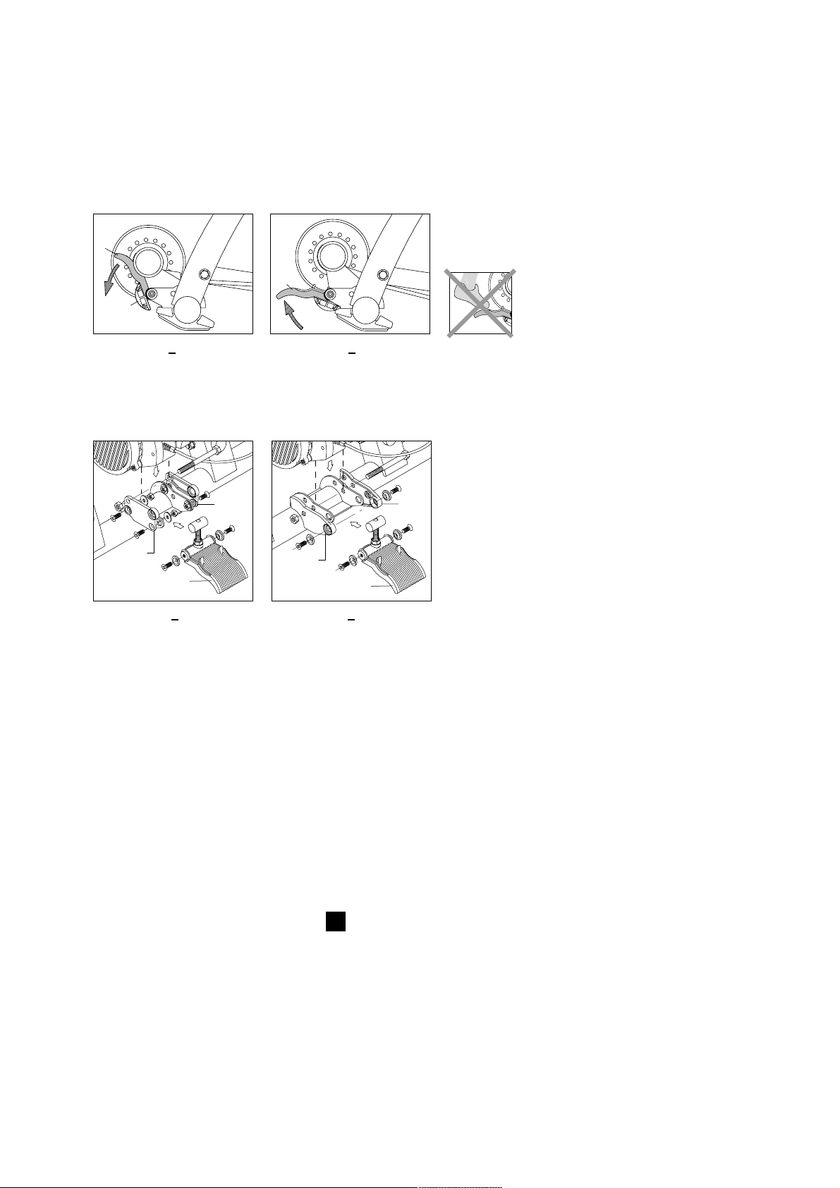
78
Montaje del Basic
E
8 Con la manivela H se puede colocar y soltar el rodillo del freno de resistencia contra la cubierta
de la bicicleta. (fig. 5 y 6). Cuando la manivela H esté sobre la cubierta, el botón de ajuste R
puede variar la presión del rodillo sobre la rueda. El rodillo debe estar bien presionado contra
la cubierta de la rueda de manera que no se derrape al pedalear.
Montaje diferente para bicicletas con diámetro de rueda divergente
Antes de que montar la manivela completa al cuadro, véase el punto 5 de las instrucciones,
se han de fijar laminas de elevación o alargamiento.
Diámetro 610 - 640 mm: fijar láminas de elevación W con 4 pernos, tuercas y arandelas (fig. 7).
Diámetro 690 -720 mm: fijar láminas de alargamiento Z (fig. 8).
Consejos
- Antes de utilizar el ergotrainer o después de haber desplegado el caballete, verifica la posición
correcta de la empuñadura E, para evitar cualquier daño al caballete.
- Durante el montaje, procura que el simulador no se caiga sobre el volante magnético.
Esto podría ocasionar un desequilibrio en el eje de giro y provocar vibraciones.
- Asegúrate que la rueda esté bien hinchada (mínimo 6 atmósferas, 4 para una BTT).
- Para las BTT, es preferible utilizar un perfil de rueda total o parcialmente liso, ya que un perfil
de tacos podría originar ruidos y deslizamiento de la rueda.
- Evita frenar bruscamente durante una sesión de entrenamiento en el CycleForce. Si accionas el
freno trasero, el volante magnético sigue rodando por inercia, sometiendo así la cubierta a un
desgaste innecesario.
- Comprueba periódicamente que los tornillos y tuercas del entrenador siguen bien ajustados.
- Las pruebas han demostrado que en caso de utilizaciones extremas, el rodillo no experimentaba
ningún recalentamiento. Si que puede suceder, en caso de uso intensivo, que se recaliente un
poco la carcasa. Entonces, se aconseja dejarla enfriar unos instantes después de cada utilización
antes de tocarla de nuevo.
H
R
H
5 6
W
W
H
Z
Z
H
7 8
Page 79

79
Montaje del Basic
Conexión del ordenador Basic
Una vez hayas colocado la bicicleta sobre el CycleForce, conecta el ordenador Basic de la
siguiente manera:
1 Monta el ordenador Basic con la ayuda de las dos abrazaderas de goma P (fig. 4).
2 Conecta el ordenador al simulador de resistencia mediante el cable Q. Asegúrate de que el
cable no pueda ser arrancado con la zapatilla o el pedal durante el entrenamiento.
3 Coloca el pequeño imán de cadencia R en la parte interna de la biela izquierda (fig. 5).
4 Fija el sensor de cadencia S en la parte inferior de la vaina trasera izquierda. El sensor
debe situarse a la altura del imán, dejando aproximadamente 3 mm de separación entre el
sensor y imán. Conecta el cable del sensor al simulador de resistencia, asegurándote también,
que no se encuentra ningún obstáculo, ni que tampoco toca la rueda.
5. Introduce la clavija en el enchufe. Controla la recepción del sensor de cadencia pedalean do
hacia atrás. La palabra CAD aparece entonces en la pantalla. El Basic ya está listo para ser
utilizado.
La transpiración y la condensación pueden alterar los cristales de impresión del ordenador.
No utilices el Basic en lugares húmedos, y si fuese necesario, con el fin de evitar posibles
deterio ros, seca la pantalla tras cada utilización. Una utilización incorrecta y/o un
mantenimiento inadecuado podrían ocasionar la supresión de la garantía.
5
P
P
4
E
S
R
R
S
Q
Page 80

Instalación definitiva del ordenador
80
Una vez haya colocado la clavija en el enchufe, se ilumina
suavemente la pantalla de control. A continuación usted entra
normalmente en el programa (fig.6).
Podría empezar enseguida si no fuera que primeramente y por
única vez debe introducir el peso de su cuerpo. En el ordenador
se ha introducido de forma estandar la velocidad por km/hora
y un peso de 75 kg. Si la velocidad y el peso indicados son
correctos puede empezar enseguida con el programa normal.
Instalación de la indicación de velocidad
En el caso de que deban introducirse las indicaciones de velocidad o peso, mantenga apretadas al mismo tiempo durante 6
segundos las teclas SET y MODE. A continuación verá en pantalla
SET UP (fig. 7). Al apretar + ó - puede cambiar de km/h.
(kilómetros por hora) a mi/h (millas por hora) y a la inversa
(fig. 8). Al apretar MODE usted podrá dejar fijada su elección
de la velocidad.
Instalación del peso del cuerpo
A continuación verá el peso de 75 kg. (fig. 9). Al apretar + ó usted puede introducir el peso mediante pasos de 1 kilo (fig. 10).
Resulta importante introducir el peso correcto con el fin de que
el ordenador pueda calcular correctamente la potencia. El cálculo
de la potencia se halla ligado a su peso. El peso puede introducirse desde 40 kg hasta 120 kg, ambos inclusive.
A continuación podrá dejar indicado su peso apretando la tecla
MODE. La próxima vez, cuando se ponga nuevamente en marcha
el ordenador, éste partirá siempre del peso que se haya indicado
la última vez. Naturalmente que usted podrá variar el peso
mediante un nuevo SET UP, como por ejemplo si otra persona
va a entrenarse con el Basic.
Instalación del reloj de 24 horas
Una vez introducido el peso usted podrá introducir, si lo desea,
el reloj de 24 horas. Si no le interesa utilizar esta opción puede
prescindir de ella apretando 2 veces la tecla MODE, volviendo
al programa normal. De esta manera no le aparecerá el reloj
durante el uso de la bicicleta.
En el caso de que desee utilizar el reloj 24 horas, introduzca
primero las horas con las teclas +/-. Seguidamente aprete la
tecla MODE y podrá con las teclas +/- introducir los minutos.
Con sólo apretar una vez más la tecla MODE introducirá el
reloj y podrá entrar en el programa normal. También le aparecerá el reloj si ojea otras funciones. Al apa-gar el ordenador se cierra también el reloj.
Si a la próxima vez usted necesita el reloj deberá introducirlo
nuevamente mediante el SET UP.
KG
9
WATT ETM
SLOPE KM/h
KM/h
MI/h
6
7
8
E
2 INSTALACIÓN DEFINITIVA DEL ORDENADOR
Page 81

Uso del ordenador
81
KG
10
3 USO DEL ORDENADOR
Una vez ha sido preparado el ordenador usted puede empezar
a ir en bicicleta. Todas las operaciones que han sido descritas
puede efectuarlas en Basic estando en marcha o parado.
El Basic registra 3 clases de datos. La primera clase guarda
relación con la velocidad de su bicicleta y la trataremos a
continuación. A continuación se tratarán las demás clases
(potencia y cadencia).
Las funciones de MODE en Km/h (o Mi/h)
Bajo la tecla MODE se encuentran las funciones generales de la
bicicleta. Apretando siempre 1 vez la tecla MODE se encontrará
seguidamente con: ETM, TRP, ODO, MAX, AVS (véase esquema
del bloque). También le aparecería en esta relación el reloj si lo
hubiera introducido con anterioridad.
ETM (cronómetro)
Empiece arriba a la derecha con ETM, el cronómetro (fig. 11).
ETM es el tiempo que se está utilizando la bicicleta sin que se
haya hecho "reset" en el ordenador o se haya parado.
El cronómetro registra únicamente el tiempo de utilización de la
bicicleta. Por consiguiente usted podrá intercalar pausas, sin que
ello influya en el tiempo efectivo del ejercicio en la bicicleta. Si
para el ordenador o efectúa un "reset" durante el uso de la bicicleta, entonces el cronómetro empieza de nuevo a partir de 0.
TRP (distancia del recorrido)
Apretando una vez más MODE aparece en la parte superior
derecha TRP, la distancia del recorrido (fig.12). La distancia del
recorrido va siendo calculada siempre y cuando no se haga
“reset” en el ordenador o se apague.
ODO (distancia total)
En el paso siguiente con la tecla MODE aparece arriba a la
derecha ODO, el total del camino recorrido (fig.13). El ODO
suma las distancias de todos los recorridos y alcanza un total
máximo de 99.999 km (o millas) para empezar de nuevo a
partir de 0 km.
ETM
cronómetro
TRP
distancia del
recorrido
ODO
distancia
total
MAX
velocidad
máxima
AVS
velocidad
media
reloj
MODE
WATT TR P
SLOPE KM/h
WATT
SLOPE KM/h
WATT ODO
SLOPE KM/h
12
13
WATT ETM
SLOPE KM/h
11
E
Page 82

WATT MAX
SLOPE KM/h
14
Uso del ordenador
82
MAX (velocidad máxima)
A continuación aparece arriba a la derecha con ayuda de la tecla
MODE MAX, la velocidad máxima (fig. 14). Este es el máximo de
velocidad durante el período en que al ordenador no se la hecho
“reset” o se ha apagado.
AVS (velocidad media)
Apretando por última vez la tecla MODE aparece arriba a la
derecha AVS, velocidad media (fig.15). La velocidad media se
calcula sobre el período en que al ordenador no se le ha hecho
“reset” o se ha apagado.
Reloj
Si usted hubiera elegido la opción de utilizar el reloj, podría
apretar todavía una vez la tecla MODE con lo que le aparecería la
imagen del reloj.
Las funciones de “reset” bajo la tecla MODE
En el caso de que usted durante un recorrido de entrenamiento
deseara situar nuevamente en 0 mediante “reset” los datos
acumulados en las indicaciones ETM, TRP, MAX y AVS, deberá
detener las piernas, procure que la velocidad quede a 0 y aprete
al mismo tiempo las teclas SET y MODE durante 1 segundo
(fig. 15). Al ODO no se le puede hacer "reset", cuando éste
alcanza la cifra de 99.999 km. entonces salta sólo a 0 km.
(o millas).
Las funciones bajo los botones + ó -
Tal como se ha dicho antes, el Basic registra tres clases de datos:
1 datos que guardan relación con su velocidad (Km/h o Mi/h).
2 datos que guardan relación con la potencia que usted mismo pro
porciona (WATT).
3 datos que guardan relación con la frecuencia del pedaleo (CAD).
Con las teclas + y - usted puede cambiar la pantalla de
velocidad a potencia, y de potencia a cadencia y a la inversa
véase el esquema del bloque).
WATT (potencia)
Apretando la tecla + podrá cambiar abajo a la derecha de
velocidad a WATT, la potencia suministrada actualmente (fig. 16)
CAD (frecuencia de pedaleo)
Apretando una vez más la tecla + o - usted cambiará en la parte
inferior derecha de WATT a CAD, la cadencia o bien la
frecuencia actual de pedaleo (fig. 17).
KM/h WATT CAD
-
+
WATT ET M
SLOPE KM/h
15
MAX
SLOPE WATT
16
WATT MAX
SLOPE CAD
17
E
Page 83

Las funciones de MODE en WATT
Cuando la pantalla deje ver la potencia WATT, usted podrá disponer de las funciones bajo la
tecla MODE. El cronómetro (ETM) continua naturalmente funcionando, pero el TRP, MAX y
AVS significan durante la indicación WATT respectivamente utilización de recorrido, potencia
máxima y media.
El término utilización del recorrido necesita todavía una explicación. Sin que al ordenador se
le haya hecho “reset” o haya sido apagado él calcula, en base al cronómetro y la potencia
suministrada, el consumo del recorrido (Kcal) expresado en kilocalorías.
Las funciones MODE en el CAD
Si la pantalla deja ver la frecuencia de pedaleo (CAD), TRP, MAX y AVS significan
respectivamente el total de vueltas a los pedales durante el recorrido, el máximo
y el promedio de la frecuencia del pedaleo.
Mediante la utilización del botón MODE y + y - podrá experimentar y combinar datos diversos.
Al apretar una tecla aparecen rápidamente una serie de datos. De esta manera se familiarizará
rápidamente con el ordenador. En el espacio de tiempo de diez minutos sabrá encontrar
aquellas combinaciones que considere más agradables o más importantes.
Uso del ordenador
83
KM/h
WATT
CAD
MODE ETM
TRP
ODO
MAX
AVS
MODE
MODE
MODE
MODE
MODE
ETM
TRP
MAX
AVS
TRP
MAX
AVS
Cronómetro
Distancia recorrido
Distancia total
Velocidad máxima
Velocidad media
Cronómetro
Utilizacion del recorrido
Potencia máxima
Potencia media
Pedaladas por recorrido
Frecuencia de pedaleo máxima
Frecuencia de pedaleo media
Reloj
Reloj
Reloj
E
Page 84

Uso del ordenador
84
WATT MAX
SLOPE KM/h
WATT
SLOPE KM/h
MAX
18
19
La función SET en el SLOPE (resistencia en la pendiente)
Ahora avanzamos un paso. Con el Basic tiene también la posibili-
dad de simular una resistencia artificial. En el Basic esto se
consigue mediante la resistencia de pendiente (SLOPE). Esta
resistencia actúa sobre el rodillo del entrenador. Usted deberá
tener presente que cuanto más rápido vaya girando el rodillo más
fácil será para el ordenador frenarlo. En el caso de una velocidad
baja y de una frecuencia de pedaleo baja será más difícil para el
Basic frenar el rodillo que en el caso de una velocidad alta y una
frecuencia alta de pedaleo. De ahí que se hayan introducido en el
SLOPE una serie de catorce pasos que van desde -4 hasta + 9
ambos inclusive.
La resistencia de la pendiente depende del peso a partir de
los valores superiores al 0. Al apretar la tecla SET se enciende
intermitentemente en la parte inferior izquierda la resistencia de
la pendiente (SLOPE) (fig. 18) que ha sido introducida de forma
estándar en 0. Con las teclas + y - podrá variar la resistencia de
las pendientes de -4 hasta + 9 ambas inclusive (fig. 19). Después
de apretar la tecla MODE podrá fijar la nueva resistencia de la
pendiente.
Usted podría pensar que la resistencia de una pendiente de +9
se corresponde con el ángulo de +9 grados y una resistencia
de pendiente de -4 con un ángulo de pendiente de -4 grados.
Usted comprenderá que si mantiene las piernas quietas en
una resistencia de pendiente de -4, el entrenador no podrá por
sí mismo continuar bajando la montaña. Los pasos de -4 hasta
+9 ambos incluidos han sido utilizados para proporcionarle al
entrenador los cálculos suficientes y las adaptaciones en
resistencia a la potencia programada.
La función SET en el WATT prg. y la potencia programada
Finalmente podrá avanzar aún un paso más. Si una vez apretada
la tecla SET y el intermitente de la resistencia de pendiente (fig.
20) apreta una vez más la tecla SET, entonces empezará la poten-
cia programada (WATT prg) con luz intermitente en la parte
superior izquierda (fig. 21). El ordenador prueba durante la
potencia programada, independientemente del cambio de
marcha pisado e independientemente de la frecuencia de
pedaleo, adaptar de tal manera la resistencia al rodillo, que usted
pueda pedalear siempre en consonancia con la potencia-progra-
mada y deseada. En el caso de que usted cambie la frecuencia de
su pedaleo el ordenador adapta inmediatamente la resistencia al
rodillo, con lo que usted continua efectuando siempre y perma-
nentemente la misma potencia. Si usted varia su resistencia el
ordenador hace exactamente lo mismo, adaptando la resistencia
al rodillo.
Puede introducir la potencia programada apretando las teclas
+ y - en pasos de 10 watt (fig.22) cuando funcione intermitente-
mente el WATT prg. Hemos introducido en el programa de
forma estándar la potencia de 100 watt, pero usted puede
introducir de 0 watt hasta 990 watt. La mayoría de los ciclistas
entrenarán con valores que oscilan entre 100 y 400 watt.
WATT
SLOPE KM/h
KG
MAX
WATT PRG
KM/h
MAX
20
21
E
Page 85

Uso del ordenador
85
Una vez introducida la potencia programada podrá fijar ésta
apre-tando la tecla MODE (fig. 23). Una vez almacenada la
potencia programada desaparece la cifra SLOPE tanto tiempo
como usted continúe rodando bajo el título WATT prg.
El ordenador mantiene siempre la última potencia programada
introducida, incluso aunque se apague el orde-nador. Para poder
salir de la potencia programada deberá apretar dos veces sobre
la tecla SET, con lo que volverá a estar en SLOPE.
Potencia (Watt) = Fuerza x Velocidad
La potencia programada por usted (watt) es adaptada por el
Basic mediante el SLOPE durante la utilización de la bicicleta.
Imagínese que programa una potencia de 400 watt y desea
pedalear esta potencia relativamente alta con una fuerza relativamente pequeña (por ejemplo resistencia 39x26) y una velocidad
relativamente baja (por ejemplo una frecuencia de pedaleo de
70). En este caso el SLOPE no puede proporcionar la suficiente
resistencia para alcanzar la potencia programada. Usted verá que
la indicación Watt abajo a la derecha (la potencia actual) no
coincide con la potencia programada (WATT prg).
El WATT prg empezará a parpadear arriba a la izquierda (fig. 24)
indicando que usted se halla fuera del campo de actividad del
ordenador. Mediante la adaptación de su resistencia (mayor/más
pesado) y frecuencia del pedaleo (más alto) usted mismo irá
notando cuando entre de nuevo en el campo de actividad del
ordenador. El WATT prg volverá a brillar de forma continuada.
Inversamente, si usted ha programado una potencia
relativamente baja y procura alcanzarla con gran fuerza (por
ejemplo 52x16) y una velocidad alta (por ejemplo una frecuencia
de pedaleo de 100) entonces la potencia actual empezará
lógicamente a irse saliendo de la potencia programada.
También en este caso se halla usted fuera del campo de
actividad del ordenador y por ello parpadeará arriba a la
izquierda la palabra WATT prg. Lo que debe hacer es adaptar
de tal manera la marcha y la frecuencia del pedaleo que le
permitan entrar de nuevo en el campo de actividad del
ordenador.
WATT pr g
KM/h
MAX
24
WATT pr g
KM/h
MAX
WATT pr g
KM/h
MAX
22
23
E
Page 86

Consejos para entrenamientos
86
4 CONSEJOS PARA ENTRENAMIENTOS
No existe ningún deporte en el que se exija del deportista tanta tensión durante tanto tiempa
como en el ciclismo. El ciclismo es considerado como uno de los deportes más duros en lo que
se refiere a la carga del corazón, de los pulmones y de los músculos. En cierto modo puede
decirse lo mismo sobre el ir en bicicleta con los entrenadores CycleForce Basic Tacx, incluso
más por cuanto usted desee aumentar las cargas a un nivel más alto. Por consiguiente será una
exigencia prioritaria que se someta usted anualmente a un chequeo amplio por un médico
deportivo especialista, antes que de comienzo la nueva temporada ciclista.
El entrenamiento se podría definir como: “Suministrarse sistemáticamente un estímulo para
aumentar las prestaciones”. Entrenamos con un fin. Este puede variar de adelgazar, relajar los
músculos tras un esfuerzo o ganar el oro en un campeonato. El “estímulo” que suministramos
puede constar de pedalear tranquilamente durante mucho tiempo o muy rápidamente durante
poco tiempo. Lo importante es que haya un sistema de entrenamiento escalonado. A medida
que pasa el tiempo podemos pedalear más tiempo y mayores distancias o incluso subir picos
más elevados. La palabra clave para mejorar verdaderamente las prestaciones es la variación.
Supercompensación
Cuando entrenamos, estamos provocando una perturbación en nuestro cuerpo; esta perturbación (corazón, pulmones, músculos) es restablecida y mejorada un poco en los descansos. Este
principio lo denominamos supercompensación. No es que nos hagamos más fuertes por el
entrenamiento sino justo por el descanso posterior. El siguiente momento de entrenamiento ha
de efectuarse cuando la línea de supercompensación roce el cero (fig. 25). Para hacer que
nuestra condición física mejore, se puede establecer un mínimos de 3 unidades de entrenamiento por semana. Con 2 entrenamientos se puede mantener la condición pero 1 entrenamiento
por semana no es suficiente. El esquema de entrenamiento lo puede determinar usted o un
entrenador. Es aconsejable hacer uso de un
contador del ritmo cardiaco cuando se haga
uso del CycleForce Basic.
Ejemplos de programas de entrenamiento
Empiece el entrenamiento con un calentamiento:
pedalee entre 5 y 10 minutos sin apenas
resistencia y con una frecuencia de 90/100
pedaladas por minuto. Durante este calentamiento puede efectuar ejercicios de estiramiento
de músculos (incluso en la bicicleta). El entrenamiento finaliza con un cooling down de 5 a 10
minutos y de nuevo algunos ejercicios de estiramiento. Si omite realizar el calentamiento o el
cooling down, puede sufrir lesiones.
El Tacx Basic es idóneo para entrenamientos
específicos. Antes de empezar un programa de entrenamiento es aconsejable realizar una
prueba de condición física, para conocer su rendimiento en potencia en qué pulsaciones le
corresponden. Haga a continuación, eventualmente con su entrenador, un plan (anual, mensual
y semanal) de acuerdo con sus objetivos, nivel y posibilidades. En el plan anual entrena todas las
estaciones en el Basic (es decir, no sólo cuando hace mal tiempo). Entrenar en potencia le hará
más fuerte, más rápido y mejor. Aprende a subir montañas, acelerar, aumentar su fuerza (véase
el ejemplo) e incluso simular una prueba contrarreloj.
Con el Basic también es posible realizar una prueba “Conconi”, Astrand o PWC (Physical Work
Capacity). Puede encontrar estas dos últimas pruebas en la página Web de Tacx donde, después
de introducir sus datos, puede recibir directamente los resultados.
Más consejos de entrenamientos y los últimos desarrollos: www.tacx.nl.
25
0
esfuerzo de
entrenamiento
recuperación
supercompensación
E
Page 87

Consejos para entrenamientos
87
E
Entrenamiento de recuperación
tiempo(min.) slope revoluciones resistencia características
3 1 100 mínima ligero/alta velocidad
3 1 100 1 superior ligero/alta velocidad
3 1 100 1 superior ligero/alta velocidad
3 1 100 1 superior ligero/alta velocidad
3 1 100 1 superior ligero/alta velocidad
3 1 100 1 superior ligero/alta velocidad
3 1 100 1 inferior ligero/alta velocidad
3 1 100 1 inferior ligero/alta velocidad
3 1 100 1 inferior ligero/alta velocidad
3 1 100 1 inferior ligero/alta velocidad
3 1 100 1 inferior ligero/alta velocidad
3 1 100 mínima ligero/alta velocidad
36
Eventualmente se puede repetir este entrenamiento en la marcha 2 cada dos minutos y en la mar
cha 3, repitiendo cada 1 minuto. Para una mayor variación naturalmente también puede pedalear
con 80, 90, 110 ó 120 revoluciones por minuto.
Entrenamiento de fuerza
tiempo(min.) watt revoluciones resistencia características
3 80 80/90 libre calentamiento/pedaleo tranquilo
4 140 100 modesta aumentar la velocidad
3 180 100 modesta aumentar la velocidad
2 200 100 modesta aumentar aún más la velocidad
1 240 90 modesta aumentar aún más la velocidad
3 80 120 modesta pedaleo tranquilo
4 180 60 superior velocidad baja/sentado
3 200 70 superior velocidad baja/sentado
2 220 80 superior velocidad baja/sentado
1 260 70 superior velocidad baja/sentado
5 80 80/90 libre cooling-down
31
La potencia en este entrenamiento se puede ajustar fácilmente a las exigencias/capacidades
individuales del ciclista. Comience despacio y asegúrese de que puede terminar todo el
entrenamiento. Sólo entonces tiene efecto entrenar.
Entrenamiento de montaña
tiempo(min.) slope revoluciones resistencia características
4 2 80/90 libre pedaleo ligero/alta velocidad
3 3 > 80 libre intente mantener una alta velocidad
1 7 60 53-14 de pie en los pedales
5 1 > 100 42-16 alta frecuencia de pedaleo
2 5 > 80 53-15 alternar sentado/de pie cada 30''
2 6 90/100 42-16 mantenerse sentado
5 1 110/130 42-16 alta frecuencia de pedaleo
10
1 libre libre cooling-down
32
Page 88

Disfunciones
88
Causas posibles
1 El suelo no está liso
2 El entrenador no ha sido bien
montado
3 La bicicleta no está bien
colocada en el entrenador
4 El aparato no está bien
desplagado
1 Baja presión en las ruedas
2 La presión de del rodillo so-
bre la cubierta no es suficiente
1 El perfil de la rueda
2 Piedrecita en la rueda
1 La temperatura ambiente es
demasiado baja o alta
2 La orientación de la pantalla
no es la adecuada
3 El ordenador no está bien
conectado al simulador
4 El sudor puede haber oxida-
do la pletina del circuito
impreso
5 La pletina del volante magné-
tico está dañada
1 El Basic ha sido interrumpido
durante la escritura de los
valores p.e. desconexión de
la corriente durante el
entrenamiento.
Solución
1 Sitúe el entrenador sobre un piso liso
2 Controle si está bien apretados todos
los tornillos y tuercas
3 Controle a ver si ha sido montado el
blocaje suministrado
4 Despliéguelo del todo
1 Controle la presión de las ruedas,
mínimo 6 atmósferas
2 Fíjelo fuertemente contra la rueda
1 Instale una rueda con el perfil total
o parcialmente liso
2 Controle que no se dañe la rueda
1 Utiliza el Excel a temperatura ambien-
te entre 5º y 35º C (40ºF y 95º)
2 Orienta la posición de la pantalla de
forma que esté lo más perpendicular
posible a la mirada
3 Comprueba el cable y contactos de la
clavija en el ordenador y simulador
4 Hay que remplazar la pletina
5 Hay que remplazar la pletina.
1 Reinicalización completa de la compu-
tadora: Mantenga la tecla SET presionada durante 5 segundos mientras se
conecta el cable en la parte inferior de
la moputadora, a continación prsione
la tecla MODE dos veces.
Error
1 Fenómeno de vibra-
cìones en la bicicleta
2 Partículas de cubier-
ta de quedan pegadas al rodillo
3 Funcionamiento
muy ruidoso durante un entrenamiento
4 La pantalla no se
puede leer o se lee
muy mal
5 Valores erróneos en
el display
5 DISFUNCIONES
El simulador
Ordenador Basic y simulador de resistencia
E
Page 89

Disfunciones
89
Solución
1 Comprueba el cable y contactos de la
clavija en el ordenador y simulador.
Pueden estar sucios, oxidados o torcidos
2 El Basic funciona correctamente entre
220 y 230 V / 50Hz.
3 Hay que remplazar la tapa del simula-
dor
4 Hay que remplazar la pletina
1 Hay que remplazar la cadena
2 Comprueba la presión de la cubierta
trasera
3 Después de aproximadamente 3
minutos, la unidad llega a su temperatura de funcionamiento
4 Utiliza el Basic a temperatura ambien-
te entre 5º y 35º C (40ºF y 95ºF)
1 Conecta el sensor de cadencia ó
instala un imán en buen estado
2 Asegúrate que la distancia entre el
sensor y el imán es de 3 mm aprox
3 Conecta un sensor nuevo.
4 Controla que la clavija esté bien intro-
ducida dentro del enchufe
1 Comprueba el cable y contactos de la
clavija en el ordenador y simulador
2 Ajusta la manilla de regulación del
volante magnético para evitar que
patine la rueda
3 Instala una nueva pletina en la unidad
magnética
Causas posibles
1 No sabemos si ese elemento
debería ser indicado
2 La tensión de la red eléctrica
es demasiado baja
3 Debido a un golpe, se han
soltado algunos imanes de la
unidad magnética
4 La pletina del simulador está
dañada
1 La cadena de la bicicleta está
usada
2 La presión de las cubiertas es
es insuficiente
3 El volante magnético todavía
no ha alcanzado la temperatura adecuada
4 La temperatura ambiente es
demasiado baja
1 El sensor de cadencia no está
conectado ó el imán se ha
salido de su habitáculo
2 El sensor está alejado del
imán.
3 Ruptura del cable del sensor
de cadencia
4 La clavija del sensor no está
bien conectada dentro del
racor del volante magnético
1 Los impulsos de velocidad no
llegan hasta el ordenador
2 La rueda no está en contacto
con el volante magnético
3 El sensor de velocidad del
volante magnético es
defectuoso
Error
6 Notas una potencia
desarrollada más
baja que la indicada
en pantalla
7 Notas una potencia
desarrollada más
alta que la indicada
en pantalla
8 La cadencia de
pedaleo se queda
en el nivel 0
9 La velocidad se
queda en el nivel 0
E
Page 90

DECLARACIÓN DE CONFORMIDAD CE
De Acuerdo con la directiva europea para las máquinas 93/68CE anexo II A.
Por la presente, Technische Industrie Tacx bv, Rijksstraatweg 52, 2241 BW Wassenaar,
Países Bajos, declara que la máquina a continuación detallada, cumple, tanto por su concepción y
fabricación, como por la versión que hemos puesto en circulación, con los criterios de seguridad
y de higiene establecidos por la directiva CE. En caso de modificación de la máquina sin nuestra
aprobación, la presente declaración perdería su validez.
Producto: CycleForce
Tipo: Basic
Datos técnicos: 220V AC 50 Hz
Directiva europea
Directiva CE sobre Máquinas (89/392/CE), versión 93/68CE - Directiva CE sobre Baja Tensión
(73/23/CE) - Directiva CE sobre Tolerancia Electromagnética (89/336/CE), versión 93/31/CE.
Normas armonizadas aplicadas:
EN 50081-1 / EN 55022 (1993) clase B / EN 50082-1 / EN 61000-4-2; EN 61000-4-3; EN
61000-4-5 y EN 61000-4-6.
La conformidad permanente de los aparatos de serie con los criterios de la directiva europea
actual y las normas aplicadas están garantizada por medidas internas de la empresa.
Wassenaar, 23-09-2000
J.H.J. Tacx
Velocidad(Km/h o Mi/h)
Velocidad actual
0,1 a 99,9 Km/h o Mi/h
Cronómetro, tiempo de utilización
Capacidad: 8 horas, 59 minutos,
59 segundos
TRP distancia del recorrido
Capacidad: 999,9 kilómetros o millas
ODO distancia total
Capacidad: 99.999 kilómetros o millas
MAX velocidad máxima
Capacidad: 99,9 kilómetros o millas
AVS velocidad media
Capacidad: 99,9 kilómetros o millas
Potencia (watt)
Potencia actual
Capacidad: 2 hasta 999 WATT
TRP utilzación del recorrido en Kcal
Capacidad: 999,9 Kcal
MAX potencia máxima
Capacidad: 999 WATT
AVS potencia media
Capacidad: 999 WATT
Características técnicas & Declaración de conformidad CE
90
6 CARACTERÍSTICAS TÉCNICAS
Frecuencia de pedaleo (cadencia)
Frecuencia de pedaleo actual
Capacidad: 0-250 pedaladas por recorrido
AVS frecuencia de pedaleo media
Capacidad: 0-250 pedaladas por recorrido
MAX frecuencia de pedaleo máxima
Capacidad: 0-250 pedaladas por recorrido
TRP pedaladas por minuto
Capacidad: 99.999 pedaladas
Varios
Reloj de 24 horas
23 horas, 59 minutos, 59 segundos
SLOPE, resistencia en la pendiente
Capacidad: 40 WATT hasta 990 WATT
Watt prg
Capacidad: 40 WATT hasta 990 WATT
Alcance de temperatura
10ºC a 40ºC (50ºF a 104ºF)
E
Page 91

Garantía
91
7 GARANTÍA
Los productos de Tacx han sido elaborados conforme a las normas de calidad más estrictas.
Los productos de Tacx tienen una garantía de un (1) año desde la fecha de compra aplicable c
contra los defectos de producción o material. Guarde bien el vale de caja pues éste es su justifi
cante de la compra. Los accesorios que por el uso normal sufren desgaste no caen en la garantía.
La garantía vence si el producto muestra claramente:
1 que se ha destinado para un uso distinto que para el que ha sido fabricado
2 que el uso, las reparaciones o el desmontaje se han efectuado de una manera inexperta
3 daños como consecuencia de accidentes o negligencia
4 corrosión de la pantalla del ordenador por la transpiración y/o la condensación
5 que se trata de daños causados por el envío o transporte del producto
Las piezas que muestren desgaste en el uso normal no entran dentro de la garantía.
Gastos de envío
- los gastos de envío al suministrador de Tacx o el Centro de Servicios de Tacx corren por cuenta
del cliente
- los aparatos reparados son enviados a cargo del Centro de Servicios de Tacx.
Procedimiento
- Cuando el producto, por algún motivo, no funcione como es debido a pesar de hacerse un
uso normal del mismo, llévelo junto con el justificante de la compra (copia) y el formulario de
servicio rellenado a su suministrador. También lo puede enviar directamente al Centro de
Servicios de Tacx en su país.
- El Centro de Servicios de Tacx sólo puede dar trámite a estos envíos si van acompañados de un
formulario de servicio rellenado.
- Si se determina que el producto cae bajo la garantía, el Centro de Servicios de Tacx lo reparará
o sustituirá de manera gratuita en el plazo de 30 días.
- La determinación si un producto cae bajo la garantía, es únicamente competencia de Technische
Industrie Tacx bv. Si un producto no cae bajo la garantía, el aparato será reparado y los gastos
correrán por cuenta del cliente. Si los gastos de la reparación superan los 50,00 euros, se le
presentará previamente una indicación del precio. Dependiendo de su respuesta, el producto
será reparado o devuelto tal como se recibió.
Instrucciones para la devolución
1 Envíe sólo piezas, del producto Tacx, que entren en consideración para su reparación.
2 Empaquete todo con cuidado en el embalaje original. Los daños de transporte correrán por su
cuenta.
3 Cumplimente totalmente y claramente el formulario de servicio.
4 Adjunte una fotocopia del comprobante de venta.
5 Envíe el paquete franqueado y eventualmente asegurado al Centro de Servicio de Tacx de su país.
Responsabilidad
- Technische Industrie Tacx bv se reserva el derecho de adaptar, mejorar o finalizar la producción
de los productos sin aviso previo.
- Tacx bv no está obligada a instalar nuevos aspectos/elementos en productos vendidos con
anterioridad, incluso cuando los productos son devueltos conforme a una garantía.
- Tacx bv puede reemplazar piezas defectuosas por piezas semejantes de la misma calidad si no
hay disponibles piezas idénticas.
- Tacx bv no asume ninguna responsabilidad por los daños directos, incidentales o especiales que
sean consecuencia de o guarden relación con el uso de los productos.
E
Page 92

92
Carta de servicio
CARTA DE SERVICIO
En el momento de la devolución de piezas para su reparación, utiliza esta carta de servicio para
indicar tus datos. Adjúntala a tu CycleForce Basic.
Apellido, nombre: . . . . . . . . . . . . . . . . . . . . . . . . . . . . . . . . . . . . . . . . . . . . . . . . . . . . . . . . . . . . . . . . . . . . . . . . . . . . . . . . . . . . . . . . . . . . . . . . . . . . . . . . . . . . . . . . . . . . . . . . . . . . . . . . . . . . . . . . . .
Dirección: . . . . . . . . . . . . . . . . . . . . . . . . . . . . . . . . . . . . . . . . . . . . . . . . . . . . . . . . . . . . . . . . . . . . . . . . . . . . . . . . . . . . . . . . . . . . . . . . . . . . . . . . . . . . . . . . . . . . . . . . . . . . . . . . . . . . . . . . . . . . . . . . . . . . . . . .
Código postal: . . . . . . . . . . . . . . . . . . . . . . . . . . . . . . . . . . . . . . . . . . . . . . . . . . . . . . . . . . . . . . . . . . . . . . . . . . . . . . . . . . . . . . . . . . . . . . . . . . . . . . . . . . . . . . . . . . . . . . . . . . . . . . . . . . . . . . . . . . . . . . . .
Localidad: . . . . . . . . . . . . . . . . . . . . . . . . . . . . . . . . . . . . . . . . . . . . . . . . . . . . . . . . . . . . . . . . . . . . . . . . . . . . . . . . . . . . . . . . . . . . . . . . . . . . . . . . . . . . . . . . . . . . . . . . . . . . . . . . . . . . . . . . . . . . . . . . . . . . . . .
País: . . . . . . . . . . . . . . . . . . . . . . . . . . . . . . . . . . . . . . . . . . . . . . . . . . . . . . . . . . . . . . . . . . . . . . . . . . . . . . . . . . . . . . . . . . . . . . . . . . . . . . . . . . . . . . . . . . . . . . . . . . . . . . . . . . . . . . . . . . . . . . . . . . . . . . . . . . . . . . . . .
Teléfono: . . . . . . . . . . . . . . . . . . . . . . . . . . . . . . . . . . . . . . . . . . . . . . . . . . . . . . . . . . . . . . . . . . . . . . . . . . . . . . . . . . . . . . . . . . . . . . . . . . . . . . . . . . . . . . . . . . . . . . . . . . . . . . . . . . . . . . . . . . . . . . . . . . . . . . . . . .
Modelo: Tacx Basic
Fecha de compra: ...........................................................................................................................
Número de serie del ordenador: . . . . . . . . . . . . . . . . . . . . . . . . . . . . . . . . . . . . . . . . . . . . . . . . . . . . . . . . . . . . . . . . . . . . . . . . . . . . . . . . . . . . . . . . . . . . . . . . . . . . . . . . . . . . . .
Albarán de compra (o copia) adjunto ?
Garantía expirada ?
si no
si no
Descripción de la avería: . . . . . . . . . . . . . . . . . . . . . . . . . . . . . . . . . . . . . . . . . . . . . . . . . . . . . . . . . . . . . . . . . . . . . . . . . . . . . . . . . . . . . . . . . . . . . . . . . . . . . . . . . . . . . . . . . . . . . . . . . . . .
. . . . . . . . . . . . . . . . . . . . . . . . . . . . . . . . . . . . . . . . . . . . . . . . . . . . . . . . . . . . . . . . . . . . . . . . . . . . . . . . . . . . . . . . . . . . . . . . . . . . . . . . . . . . . . . . . . . . . . . . . . . . . . . . . . . . . . . . . . . . . . . . . . . . . . . . . . . . . . . . . . . . . . . . . .
. . . . . . . . . . . . . . . . . . . . . . . . . . . . . . . . . . . . . . . . . . . . . . . . . . . . . . . . . . . . . . . . . . . . . . . . . . . . . . . . . . . . . . . . . . . . . . . . . . . . . . . . . . . . . . . . . . . . . . . . . . . . . . . . . . . . . . . . . . . . . . . . . . . . . . . . . . . . . . . . . . . . . . . . . .
. . . . . . . . . . . . . . . . . . . . . . . . . . . . . . . . . . . . . . . . . . . . . . . . . . . . . . . . . . . . . . . . . . . . . . . . . . . . . . . . . . . . . . . . . . . . . . . . . . . . . . . . . . . . . . . . . . . . . . . . . . . . . . . . . . . . . . . . . . . . . . . . . . . . . . . . . . . . . . . . . . . . . . . . . .
. . . . . . . . . . . . . . . . . . . . . . . . . . . . . . . . . . . . . . . . . . . . . . . . . . . . . . . . . . . . . . . . . . . . . . . . . . . . . . . . . . . . . . . . . . . . . . . . . . . . . . . . . . . . . . . . . . . . . . . . . . . . . . . . . . . . . . . . . . . . . . . . . . . . . . . . . . . . . . . . . . . . . . . . . .
Información adicional para Centro de Servicios de Tacx: . . . . . . . . . . . . . . . . . . . . . . . . . . . . . . . . . . . . . . . . . . . . . . . . . . . . . . . . . . . . . . . . . . . . .
. . . . . . . . . . . . . . . . . . . . . . . . . . . . . . . . . . . . . . . . . . . . . . . . . . . . . . . . . . . . . . . . . . . . . . . . . . . . . . . . . . . . . . . . . . . . . . . . . . . . . . . . . . . . . . . . . . . . . . . . . . . . . . . . . . . . . . . . . . . . . . . . . . . . . . . . . . . . . . . . . . . . . . . . . .
. . . . . . . . . . . . . . . . . . . . . . . . . . . . . . . . . . . . . . . . . . . . . . . . . . . . . . . . . . . . . . . . . . . . . . . . . . . . . . . . . . . . . . . . . . . . . . . . . . . . . . . . . . . . . . . . . . . . . . . . . . . . . . . . . . . . . . . . . . . . . . . . . . . . . . . . . . . . . . . . . . . . . . . . . .
. . . . . . . . . . . . . . . . . . . . . . . . . . . . . . . . . . . . . . . . . . . . . . . . . . . . . . . . . . . . . . . . . . . . . . . . . . . . . . . . . . . . . . . . . . . . . . . . . . . . . . . . . . . . . . . . . . . . . . . . . . . . . . . . . . . . . . . . . . . . . . . . . . . . . . . . . . . . . . . . . . . . . . . . . .
. . . . . . . . . . . . . . . . . . . . . . . . . . . . . . . . . . . . . . . . . . . . . . . . . . . . . . . . . . . . . . . . . . . . . . . . . . . . . . . . . . . . . . . . . . . . . . . . . . . . . . . . . . . . . . . . . . . . . . . . . . . . . . . . . . . . . . . . . . . . . . . . . . . . . . . . . . . . . . . . . . . . . . . . . .
. . . . . . . . . . . . . . . . . . . . . . . . . . . . . . . . . . . . . . . . . . . . . . . . . . . . . . . . . . . . . . . . . . . . . . . . . . . . . . . . . . . . . . . . . . . . . . . . . . . . . . . . . . . . . . . . . . . . . . . . . . . . . . . . . . . . . . . . . . . . . . . . . . . . . . . . . . . . . . . . . . . . . . . . . .
. . . . . . . . . . . . . . . . . . . . . . . . . . . . . . . . . . . . . . . . . . . . . . . . . . . . . . . . . . . . . . . . . . . . . . . . . . . . . . . . . . . . . . . . . . . . . . . . . . . . . . . . . . . . . . . . . . . . . . . . . . . . . . . . . . . . . . . . . . . . . . . . . . . . . . . . . . . . . . . . . . . . . . . . . .
. . . . . . . . . . . . . . . . . . . . . . . . . . . . . . . . . . . . . . . . . . . . . . . . . . . . . . . . . . . . . . . . . . . . . . . . . . . . . . . . . . . . . . . . . . . . . . . . . . . . . . . . . . . . . . . . . . . . . . . . . . . . . . . . . . . . . . . . . . . . . . . . . . . . . . . . . . . . . . . . . . . . . . . . . .
E93I
Page 93

Contenuto della confezione
Assicuratevi che tutte le parti siano
incluse nella confezione
- Basic computer
- Pedana Tacx CycleForce
- Unità Mag
- Sachetto di misuratore di cadenza
- Manuale
T1424.01
2x
T1424.02
2x
T1465.012xT1465.08
2x
T1402
1x
T1408.11
1x
T1410.021xT1410.04
2x
T1410.06
1x
T1423.15
2x
T1424.03
2x
T1461.19
2x
T1615.18
1x
T1466.01
1x
T1466.021xT1466.03
1x
T1466.04
1x
T1260.074xT1461.19
4x
T2459.03
4x
- T1466 Sacchetto di montaggio per il set adattatore
- T1615 Sachetto di montaggio pedana
- Tappo & piede
Page 94

94
INDICE
1 Montaggio del Basic
Montaggio del trainer 95
Installazione del computer 97
2 Operazioni uniche di installazione del computer
Regolazione dell'indicatore di velocità 98
Regolazione del peso corporeo 98
Regolazione dell'orologio 24 ore 98
3 Uso del computer
Funzioni MODE in Km/h (o Mi/h) 99
Funzioni di “reset” ragruppate sotto il tasto MODE 100
Funzioni dei tasti + e - 100
Funzioni del MODE con l'indicazione WATT 101
Funzioni del MODE con l'indicazione CAD 101
Funzione SET in SLOPE 102
Funzione SET in WATTprg 102
Potenza (watt) = Forza x Velocità 103
4 Consigli per l'allenamento
Super-comensazione 104
Esempi di programmi di allenamento 104
5 Constatazione di difetti 106
6 Specifiche tecniche &
Dichiarazione di conformità CE 108
7 Termini di garanzia
Procedura 109
Istruzioni per la restituzione al mittente 109
Modulo per l'assistenza 110
Simboli utilizzati
Indica un argomento importante. Fare attenzione!
Indica un suggerimento importante. Informazione utile.
Indice
I
Page 95

Montaggio del basic
95
I
1 MONTAGGIO DEL BASIC
L’ergometro CycleForce Basic è costituito dalle telaio pieghevole sul quale montare la bicicletta
(l’ergometro CycleForce è adatto di serie a biciclette da corsa, ibride e mountain bike con ruota
630 - 690 mm di diametro) e Computer Basic.
Montaggio del trainer
Il montaggio e la messa a punto del trainer avvengono una volta sola e vanno
eseguiti in questo modo:
1 Infilare il dado A nel tappo B e infilare quest’ultimo nel tubo del telaio (fig. 1).
2 Montare il piede C sul telaio servendosi della vite D. Avvitare la vite D, ma fare
in modo che il piede si possa ancora posizionare liberamente.
3 Aprire l’apparecchio e collocarlo su una superficie piana e resistente. L’apparec-
chio si può aprire e chiudere completamente dopo aver premuto fino in fondo
la maniglia E (fig. 1).
4 Spostare il piede C fino a farlo arrivare nella posizione giusta (fig. 2). Avvitare completamente
la vite D e fissare la gomma antislittante F (fig. 4).
5 Assemblare i due anelli di gomma G e la parte K all’unità H (fig. 3). Quindi assemblare l’unità
completa al telaio, spingere I nella parte K dell’unità e avvitare il dado J finchè l’unità magnetica
si sarà fissata saldamente mantenendo tuttavia la possibilità di muoversi (fig. 4).
6 Sostituire il dispositivo di bloccaggio a sgancio rapido della ruota posteriore con l’apposito bloc-
caggio X fornito dalla Tacx. Ciò garantisce alla morsa adattamento e stabilità ottimali. Collocare
la bicicletta sull’ergometro e regolare la vite a farfalla L dell’ergometro in modo che la ganascia
M si possa chiudere senza troppo sforzo. Forzarla può causare danni.
7 Fissare la vite a farfalla L girando il dado a farfalla N fino al suo arresto.
E
A
D
C
B
C
1
2
10 mm
13 mm (2x)13
mm (2x)
J
LN
X
M
E
I
K
H
F
H
K
G
3
Page 96

96
Montaggio del basic
I
8 Con la leva H è possibile avvicinare e allontanare il rullo dell’unità magnetica dallo pneumatico.
(fig. 5 & 6). Dopo aver chiuso la leva H, si può usare la manopola R per regolare la pressione
del rullo contro lo pneumatico. Assicuratevi che il rullo sia saldamente appoggiato allo
pneumatico evitare che questo scivoli.
Differenze delle modalità di montaggio per biciclette con un diverso diametro di ruota
Prima di procedere al montaggio del manubrio completo sul telaio, operazione per cui rimandiamo al punto 5 delle istruzioni, occorre fissare le fasce di rialzo e di prolunga.
Diametro di ruota compreso nell’intervallo 610 - 640 mm: fissare le fascette di rialzo W con
4 bulloni, dadi e anelli (fig. 7).
Diametro di ruota compreso nell’intervallo 690 - 720 mm: fissare le prolunghe Z (fig. 8).
Suggerimenti
- Prima di usare l’ergometro, si consiglia di controllare che, una volta aperto l’apparecchio, la
maniglia E sia posizionata all’indietro fino in fondo. Con ciò si evitano danni al telaio.
- Assicurarsi che l’unità non venga appoggiata sul volano durante l’assemblaggio. Ciò potrebbe
provocare uno sbilanciamento dell’asse causando vibrazioni.
- Assicurarsi che il pneumatico sia gonfiato bene (almeno sei atmosfere) Le MTB dovrebbero
avere preferibilmente copertoni con profilo totalmente o parzialmente liscio. Un profilo ruvido
può causare rumore e far scivolare la ruota.
- Mentre usate il cicloergometro non frenate mai improvvisamente. Quando frenate sulla ruota
posteriore il volano continua il suo movimento, per cui si viene a creare un inutile logorio del
copertone posteriore.
- Controllare regolarmente che viti e dadi dell’ergometro siano ben saldi.
- Alcuni test hanno dimostrato che l’unità non si surriscalda mai, nemmeno durante prestazioni
estreme. Può però accadere che l’involucro dell’unità magnetica si surriscaldi in maniera notevole
dopo un uso prolungato e intensivo. Subito dopo l’uso lasciate quindi sempre raffreddare l’unità
prima di toccarla.
H
R
H
5 6
W
W
H
Z
Z
H
7 8
Page 97

97
Montaggio del basic
Installazione del computer
Dopo aver posto la bicicletta sul telaio, potete collegare il computer nel modo seguente:
1 Montate il computer sul manubrio usando le due fascette di gomma P per il fissaggio (fig. 4).
2 Collegate il computer all’unità col cavo Q. Assicuratevi che il cavo sia fissato nel telaio in modo
da non toccarlo con le scarpe o i pedali mentre pedalate.
3 Posizionate il piccolo magnete R di fronte al sensore della cadenza all’interno dell’asse della pedi
vella sinistra (fig. 5).
4 Montate il sensore magnetico di fronte al misuratore della cadenza S sulla parte inferiore del
forcellino di sinistra. Assicuratevi che il sensore sia allo stesso livello del magnete, con una
distanza di circa 3 mm fra il magnete e il sensore. Inserite il cavo del sensore nell’unità.
Assicuratevi che il cavo sia fisso e non tocchi la ruota.
5 Inserite la spina nella presa di alimentazione. Controllate la ricezione del misuratore della cadenza
pedalando all’indietro. Sul display apparirà la parola CAD. IL Basic è ora pronto per l’uso.
Il sudore e l’umidità possono danneggiare il computer. Non usate il Basic in luoghiumidi, e, se
necessario, asciugate il display dopo l’uso. Questo aiuterà a prevenire inutili danni. Un uso e/o
una manutenzione non appropriati invalideranno la garanzia.
5
P
P
4
I
S
R
R
S
Q
Page 98

Operazioni uniche di installazione del computer
98
2 OPERAZIONI UNICHE DI
INSTALLAZIONE DEL COMPUTER
Dopo che avrete inserito la spina nella presa, il display starà
brevemente acceso per controllo. In seguito vi troverete nel
programma normale (fig. 6).
A questo punto potreste già cominciare, se non fosse per il
fatto che, prima di iniziare, dovreste innanzitutto inserire il dato
relativo al vostro peso corporeo. Il computer è installato ad una
indicazione di velocità di km/ora e ad un peso standard di 75 kg.
Se le indicazioni della velocità e del peso sono corrette, potrete
proseguire immediatamente col programma normale.
Regolazione dell'indicatore di velocità
Se dovete regolare l'indicazione di velocità e/o il peso, mantenete
contemporaneamente premuti per 6 sec. i tasti SET e MODE.
Nel display apparirà l'indicazione SET UP (fig. 7). Premendo su
+ o - passerete dall'indicazione km/h (chilometri all'ora) a quella
mi/h (Miglia Inglesi all'ora) e ritorno (fig. 8). Fissate l'indicazione di
velocità da voi scelta premendo il tasto MODE.
Regolazione del peso corporeo
Vedrete poi che l'apparecchiatura è regolata su un peso standard
di 75 kg. (fig. 9). Premendo su + o - potrete regolare il peso,
aumentandolo o diminuendolo di un chilo per volta. (fig. 10).
Per permettere al computer di raggiungere la giusta potenza
durante l'attività, è importante stabilire il peso giusto. Il calcolo
della potenza va sempre di pari passo con il vostro peso. Il peso
è regolabile da 40 a 120 kg.
Fissate quindi il vostro peso premendo il tasto MODE.
La prossima volta che il computer verrà fatto funzionare partirà
sempre dall'ultimo peso fissato. Naturalmente potrete cambiare
il peso fissato mediante un nuovo SET UP, ad esempio quando
sul Basic si vuole allenare un'altra persona.
Regolazione dell'orologio 24 ore
Dopo aver inserito i dati relativi al peso, potrete, se volete,
regolare l'orologio 24 ore. Se non ne volete fare alcun uso,
passate al programma normale, premendo 2 volte sul tasto
MODE. In questo modo l'orologio non sarà attivo durante
l'allenamento.
Se invece lo volete utilizzare, regolate innanzitutto l'ora con i
tasti +/-. Premete poi il tasto MODE e regolate quindi i minuti,
sempre con i tasti +/-. Dopo aver premuto nuovamente il tasto
MODE l'orologio sarà definitivamente regolato e vi troverete nel
programma normale. In questo modo l'orologio sarà sempre attivo, anche quando passate alle altre diverse funzioni. Nello stesso
momento in cui il computer verrà spento anche l'orologio viene
disattivato.
Se avrete bisogno nuovamente dell'orologio, dovrete regolarlo
mediante un nuovo procedimento di SET UP.
KG
9
WATT ETM
SLOPE KM/h
KM/h
MI/h
6
7
8
I
Page 99

Uso del computer
99
KG
10
3 USO DEL COMPUTER
Dopo aver installato il computer, potrete cominciare ad allenarvi.
Tutte le operazioni che in seguito descriveremo potrete
effettuarle sia mentre vi allenate con il Basic sia da fermo.
Il Basic registra 3 tipi di dati. Il primo tipo riguarda la vostra
velocità di pedalata ed è ciò di cui stiamo per parlare.
Poi verranno trattati gli altri due tipi (potenza e cadenza).
Funzioni MODE in Km/h (o Mi/h)
Il tasto MODE comprende le funzioni generali relative all'allenamento svolte dall'apparecchio. Premendo il tasto MODE continuamente, una volta dopo l'altra, vedrete apparire successivamente:
ETM, TRP, ODO, MAX, AVS (vedi lo schema in blocco).
Troverete in questo elenco anche l'orologio 24 ore, se lo
avrete fissato.
ETM (cronometro)
Si inizia in alto a destra con l'ETM, il cronometro (fig. 11). ETM è
il tempo/la durata dell'allenamento svoltosi senza che il computer
venga spento o sia in “reset”. Il cronometro registra esclusivamente il tempo che si è pedalato. Potrete quindi inframezzare
con una pausa, senza che questa possa influire sul tempo di allenamento effettivo registrato. Se spegnete il computer o lo mettete
in “reset” durante l'allenamento, il cronometro ricomincerà da 0.
TRP (distanza percorsa)
Premendo ancora una volta il tasto MODE apparirà in alto a
destra TRP, che sta ad indicare la distanza percorsa (fig. 12).
La distanza viene calcolata fin tanto che il computer non viene
spento o messo in "reset".
ODO (distanza totale)
La prossima indicazione che apparirà in alto a destra, premendo
nuovamente il tasto MODE, sarà ODO, che sta ad indicare la
distanza totale percorsa (fig. 13). L'indicazione ODO calcola
tutte le distanze percorse complessivamente e arriva ad un
massimo di 99.999 km (o miglia) per ricominciare poi
nuovamente da 0 km.
ETM
cronometro
TRP
distanza
percorsa
ODO
distanza
totale
MAX
velocitá
massima
AVS
velocitá
media
orologio
MODE
WATT TR P
SLOPE KM/h
WATT
SLOPE KM/h
WATT ODO
SLOPE KM/h
12
13
WATT ETM
SLOPE KM/h
11
I
Page 100

WATT MAX
SLOPE KM/h
14
Uso del computer
100
MAX (velocità massima)
Sempre in alto a destra, apparirà in seguito, premendo sul tasto
MODE, l'indicazione MAX, cioè la velocità massima (fig. 14).
Si tratta della velocità massima registrata per tutto il periodo
in cui il computer non è disattivato o in "reset".
AVS (velocità media)
Premendo per l'ultima volta il tasto MODE, sempre in alto a
destra apparirà l'indicazione AVS, cioè la velocità media. La
velocità media viene registrata per tutto il periodo in cui il
computer non è disattivato o in “reset”.
Orologio
Se avrete deciso di utilizzare l'orologio, dopo l'indicazione AVS,
premete nuovamente il tasto MODE e l'orologio apparirà sul
display.
Funzioni di "Reset" raggruppate sotto il tasto MODE
Se, durante l'allenamento, volete cambiare i dati indicati dalle
diciture precedentemente descritte (ETM, TRP, MAX e AVS)
ripartendo nuovamente da 0 ("reset"), smettete di muovere le
gambe, cercate di raggiungere una velocità 0 e premete
contemporaneamente, per 1 secondo, i tasti SET e MODE
(fig. 15). L'indicazione ODO non può essere regolata in questo
modo, poiché non appena arrivata ad una distanza chilometrica
di 99.999 km percorsi, scatta automaticamente la distanza
iniziale di 0 km (o miglia).
Funzioni dei tasti + e -
Come abbiamo già detto prima, il Basic registra tre tipi di dati:
1 Dati riguardanti la vostra velocità (Km/h o Mi/h).
2 Dati riguardanti la vostra potenza (WATT).
3 Dati riguardanti la vostra frequenza di pedalata (CAD).
Con i tasti + e - potete far apparire sul display le varie diciture,
da velocità a potenza e da potenza a cadenza di marcia e così
nuovamente indietro (vedi schema in blocco).
WATT (potenza)
Premendo il tasto + passate, in basso a destra, dall'indicazione
“velocità” a WATT, cioè la potenza da voi prestata in quel
momento (fig. 16).
CAD (frequenza di pedalata)
Premendo il tasto + o - ancora una volta, passerete, in basso a
destra, da WATT a CAD, cioè la cadenza di marcia o la frequenza
di pedalata registrata in quel momento (fig. 17).
KM/h WATT CAD
-
+
WATT ET M
SLOPE KM/h
15
MAX
SLOPE WATT
16
WATT MAX
SLOPE CAD
17
I
 Loading...