

Page 1
INSTALLATION AND MAINTENANCE INSTRUCTIONS
WARNING
RR2 Polarity Reversal
Relay Module
Specifications
Operating Voltage Range: 8.5 to 35 VDC
Maximum Operating Current: 25mA
Relay Contacts: 2A at 35 VDC
Operating Temperature Range: 0° to 55° C (32° to 131° F)
Operating Humidity Range: 5% to 95% non-condensing
Dimensions: 21⁄2″ x 21⁄2″ x 1″
Wire connections: 18 AWG stranded, tinned, 16″ long
General Description
The RR2 polarity reversing relay module is intended for
use with 2-wire and 4-wire detectors with built-in sounder,
such as System Sensor 2100AT, 2112/24AT, 2112/24ATR
and 2112/24AITR, 501BH, and other compatible models. It
is designed to allow all the detectors in the same loop to
sound when one of the detectors goes into alarm.
The RR2 may be used with an alarm zone that provides
coded output for fire and continuous output for burglary.
By default the RR2 will only trigger when the alarm output
is coded. In this manner, smoke detectors will only sound
from the result of a fire, and not from a burglary alarm.
When the RR2 is used in this mode, the smoke detectors
must provide for coded alarm signals if required by the
specification.
The RR2 can also be set to only trigger on continuous
alarm zone signals. When used in this mode, it will not
trigger from a coded fire alarm signal.
NOTICE: This manual shall be left with the owner/user of
this equipment.
NOTE: If your panel configuration does not match any of
the provided wiring diagrams, please contact System Sensor
technical services at 1-800-SENSOR2 for assistance.
Installation
Choose a mounting location in the control panel within
reach of the provided wire leads. Use a water/isopropyl
alcohol mixture (50/50) to clean the mounting surface.
Allow surface to dry and remove paper backing from the
Velcro and catch. Stick the Velcro in the panel and the catch
on the back of the module, then mount the module inside
the control panel. Route terminals to the appropriate terminals as noted below.
When calculating total current draw of the control panel,
remember to add current consumption (25mA) for the
power reversal relay module (RR2).
IMPORTANT: If the fire alarm output signal is coded, set
the switch on the RR2 to “OFF”. If the fire alarm output
signal is continuous, set the switch to “ON”.
Wiring
IMPORTANT: All polarities must be observed!
1. Connect the RR2 module trigger wire to the fire alarm
output terminals.
A. Alarm/Bell output: (Figures 1 and 2)
Connect the purple wire to the Alarm or Bell output.
B. Alarm relay, normally open contact: (Figures 3 and 4)
1. Connect one end of the alarm relay contact output
2. Connect the purple wire to the other end of the
2. Connect the red and black wires to the panel auxiliary
or detector power (red to positive, black to negative).
3. 2-wire models
Connect the yellow and orange wires to the panel initiat-
ing circuit (yellow to positive, orange to negative).
4-wire models
Connect the yellow and orange wires to the panel detec-
tor power circuit (yellow to positive, orange to negative).
4. 2-wire models
Connect the brown and white wires to the smoke detector
initiating circuit (brown to positive, white to negative).
4-wire models
Connect the brown and white wires to the smoke detec-
tor power circuit (brown to positive, white to negative).
NOTE: In an alarm condition, a wiring-fault
trouble state may also register at the panel
when the RR2 is used.
to positive auxiliary or detector power fire alarm
output.
alarm relay contact output.
3825 Ohio Avenue, St. Charles, Illinois 60174
1-800-SENSOR2, FAX: 630-377-6495
www.systemsensor.com
D500-44-00 1 I56-1683-02
Page 2
NOTE: If your panel configuration does not match any of the following wiring diagrams, please contact System Sensor
EOL
+
+
–
A
+
RA400Z
A
-
+
–
BELL/
ALARM
CIRCUIT
(positive signal
in alarm state)
UL LISTED
ALARM
CONTROL
PANEL
INITIATING
CIRCUIT
PURPLE
T+
+
–
+
–
AUX POWER
YELLOW
IN
+
ORANGE
IN
–
RE
D
PWR+
BLAC
K
PWR–
BROWN
OUT
+
WHITE
OUT–
Power
Not
Used
+
+
–
A
+
RA400Z
A
-
+
–
Power
Not
Used
EOL
+
+
–
A
A
UL LISTED
ALARM
CONTROL
PANEL
DETECTOR
POWER
+
–
+
–
AUX POWER
OR
DETECTOR
POWER
Power
INITIATING
CIRCUIT
+
–
+
+
–
Power
NC
NO
C
Aux
A
A
NC
NO
C
Aux
BELL/ALARM
CIRCUIT
(positive signal
in alarm state)
PURPLE
T+
YELLOW
IN+
ORANGE
IN–
RED
PWR+
BLACK
PWR–
BROWN
OUT+
WHITE
OUT–
EOL
+
+
–
A
+
RA400Z
A
-
+
–
ALARM
RELAY
(NO Contact)
UL LISTED
ALARM
CONTROL
PANEL
INITIATING
CIRCUIT
+
–
+
–
AUX POWER
Power
Not
Used
+
+
–
A
+
RA400Z
A
-
+
–
Power
Not
Used
PURPLE
T+
YELLOW
IN+
ORANGE
IN–
RED
PWR+
BLACK
PWR–
BROWN
OUT+
WHITE
OUT–
technical services at 1-800-SENSOR2 for assistance. Please refer to Figures 5 and 6 for Ademco Vista panels and Figure
7 for DSC Power 832 panels.
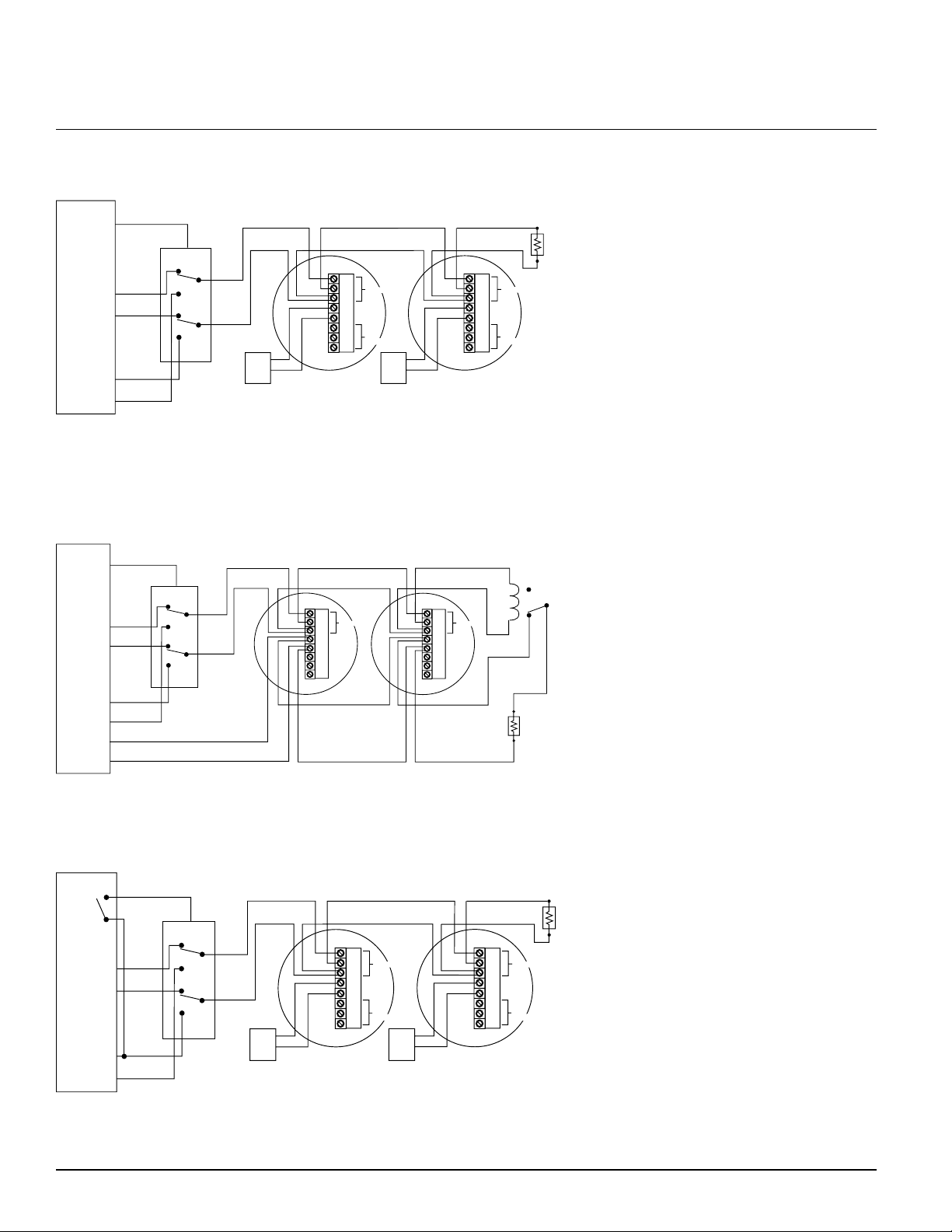
Figure 1. 2-Wire system triggered from IAC/bell circuit:
S0124-00
NOTE: If optional Style A (Class B) wiring is used, a second RR2 module must be added to enable concurrent loop
polarity reversal.
Figure 2. 4-Wire system triggered from IAC/bell circuit:
S0125-00
Figure 3. 2-Wire system triggered from alarm relay contact:
S0126-00
NOTE: If optional Style A (Class B) wiring is used, a second RR2 module must be added to enable concurrent loop
polarity reversal.
D500-44-00 2 I56-1683-02
Page 3
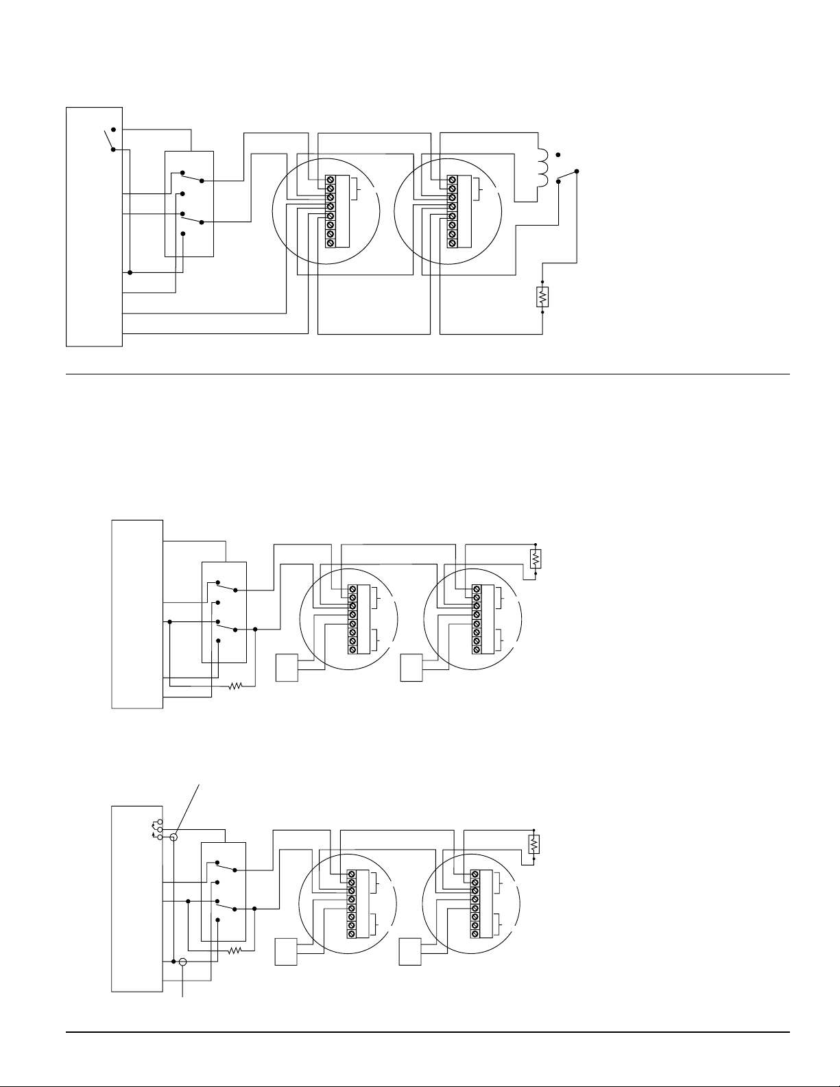
Figure 4. 4-Wire system triggered from alarm relay contact:
EOL
+
+
–
A
A
UL LISTED
ALARM
CONTROL
PANEL
DETECTOR
POWER
+
–
+
–
AUX POWER
OR
DETECTOR
POWER
Power
INITIATING
CIRCUIT
+
–
+
+
–
Power
ALARM
RELAY
(NO Contact)
NC
NO
C
Aux
A
A
NC
NO
C
Aux
EOL RELAY
(shown energized)
PURPLE
T+
YELLOW
IN+
ORANGE
IN–
RED
PWR+
BLACK
PWR–
BROWN
OUT+
WHITE
OUT–
EOL
2K OHMS
+
+
–
A
+
RA400Z
A
-
+
–
BELL/
ALARM
CIRCUIT
(positive signal
in alarm state)
2-WIRE
SMOKE
ZONE
PURPLE
T+
+
–
+
–
AUX POWER
YELLOW
ORANGE
RED
BLACK
BROWN
WHITE
Power
Not
Used
+
+
–
A
+
RA400Z
A
-
+
–
Power
Not
Used
ADEMCO
CONTROL
PANEL
APPCLICABLE
CONTROLS:
VISTA-20
VISTA-40
VISTA-50P
VISTA-32FB
VISTA-100
VISTA-128FB
SYSTEM SENSOR
POWER REVERSAL
RELAY MODULE (RR2)
(MOUNT INSIDE CONTROL ENCLOSURE)
470Ω
1/2 WATT
SYSTEM SENSOR
2100AT SMOKE DETECTORS
(UP TO 16 DETECTORS
PER ZONE)
SYSTEM SENSOR
2100AT SMOKE DETECTORS
(UP TO 16 DETECTORS
PER ZONE)
EOLR
2K OHMS
+
+
–
A
+
RA400Z
A
-
+
–
AUXILIARY
RELAY
2-WIRE
SMOKE
ZONE
+
–
+
–
YELLOW
ORANGE
RED
BLACK
BROWN
WHITE
Power
Not
Used
+
+
–
A
+
RA400Z
A
-
+
–
Power
Not
Used
ADEMCO
CONTROL
PANEL
APPCLICABLE
CONTROLS:
5110XM
5140XM
VISTA-32FB
VISTA-100
VISTA-128FB
SYSTEM SENSOR
POWER REVERSAL
RELAY MODULE (RR2)
(MOUNT INSIDE CONTROL ENCLOSURE)
470Ω
1/2 WATT
SYSTEM SENSOR
2100AT SMOKE DETECTORS
(UP TO 16 DETECTORS
PER ZONE)
SYSTEM SENSOR
2100AT SMOKE DETECTORS
(UP TO 16 DETECTORS
PER ZONE)
AUXILIARY
POWER
OUTPUT
N.C.
N.O.
NOT REQUIRED ON 5110XM
WHEN 5100XM JUMPER W3 INTACT
TAKE POWER FROM CONTROLS
AUXILIARY POWER OUTPUT ONLY
S0127-00
Connection Diagrams with Ademco Vista Panels
The connection diagrams enclosed show how to connect the 2100AT model smoke detector to the Vista panels using the
System Sensor power reversal relay module (RR2). Please make sure that the smoke detectors are connected properly to
the zones specified in the wiring diagrams for proper operation of the smoke detectors.
Figure 5. Connecting 2100AT smoke detectors to Ademco controls using RR2 module triggered from
bell/alarm circuit:
Programming information:
• The supervisory feature for the
bell circuit must be turned off.
See applicable control manual
for procedure.
RR2 Configuration:
•Set switch on RR2 to “OFF”.
S0128-00
Figure 6. Connecting 2100AT smoke detectors to Ademco controls using RR2 module triggered from
auxiliary relay:
Programming information:
• Program Auxiliary relay to
activate on alarms
• Assign Auxiliary relay as an
output for zones programmed
for fire alarm response only
(Types 9, 16, or 17)
RR2 Configuration:
• Set switch on RR2 to “ON”.
S0129-00
D500-44-00 3 I56-1683-02
Page 4
EOL
+
+
–
A
A
Power
+
+
–
Power
NC
NO
C
Aux
A
A
NC
NO
C
Aux
DSC POWER 832
RR2
AUX (+)
PGM2
PGM1
AUX
–
AUX
+
ZONE (+)
ZONE (COM)
PURPLE
YELLOW
ORANGE
RED
BLACK
BROWN
WHITE
5.6
KΩ*
*NOTE:
5.6KΩ resistor must be rated for 1/4W or greater.
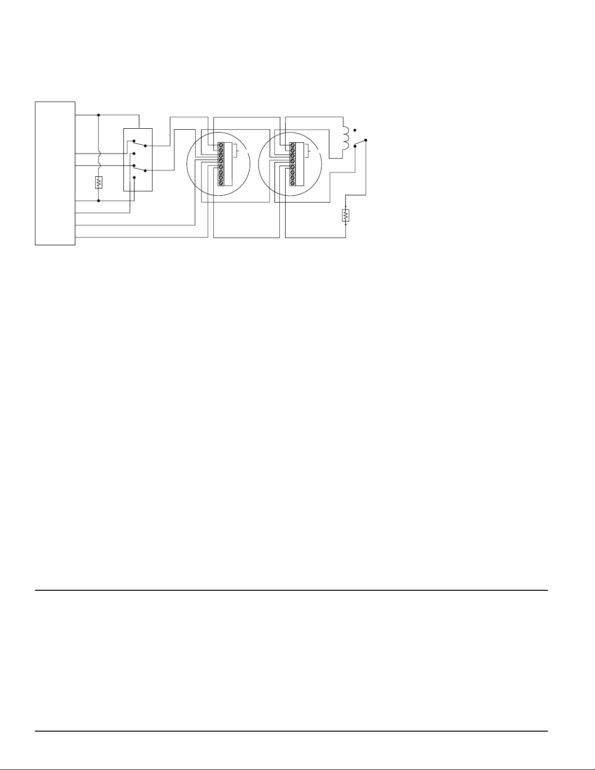
Connection diagrams with DSC Power 832 Panels
Figure 7. Connecting 2112/24AT, 2112/24ATR, and 2112/24AITR smoke detectors to DSC Power 832 controls using RR2 module with PGM output:
All smoke detectors on the 4-wire fire
zone will sound temporal 3 only from a
fire alarm event.
NOTE: • Program zone section attributes
for bell output to be pulsing.
• PGM2 must be programmed for
sensor reset.
• PGM1 must be programmed as
Burglary and Fire Bell Output (01)
with ON, ON, OFF attributes.
S0112-00
• RR2 switch must be set to OFF
(factory default setting).
Testing
Before testing, notify the proper authorities that the system
is undergoing maintenance and will temporarily be out of
service.
Test in accordance with NFPA 72 test methods, inspections,
and testing frequency.
1. Confirm that all smoke detectors connected to the RR2
module(s) contain a sounder and the sounders are activated upon power reversal.
2. Initiate an alarm with one of the smoke detectors connected to the RR2 module using any approved test
method. In the alarm state, all the detectors connected
to the RR2 module must be sounding their sounders.
3. Reset the system from the control panel. All smoke
detector sounders should be silent.
4. If the fire alarm panel also functions in burglary mode,
initiate a burglary alarm and ensure the smoke detectors
do not sound.
Three-Year Limited Warranty
System Sensor warrants its enclosed relay module to be free from defects
in materials and workmanship under normal use and service for a period
of three years from date of manufacture. System Sensor makes no other
express warranty for this smoke detector. No agent, representative, dealer,
or employee of the Company has the authority to increase or alter the
obligations or limitations of this Warranty. The Company’s obligation of
this Warranty shall be limited to the repair or replacement of any part of
the smoke detector which is found to be defective in materials or workmanship under normal use and service during the three year period commencing with the date of manufacture. After phoning System Sensor’s toll
free number 800-SENSOR2 (736-7672) for a Return Authorization number,
send defective units postage prepaid to: System Sensor, Repair Department,
D500-44-00 4 I56-1683-02
RA #__________, 3825 Ohio Avenue, St. Charles, IL 60174. Please include
a note describing the malfunction and suspected cause of failure. The
Company shall not be obligated to repair or replace units which are found
to be defective because of damage, unreasonable use, modifications, or
alterations occurring after the date of manufacture. In no case shall the
Company be liable for any consequential or incidental damages for breach
of this or any other Warranty, expressed or implied whatsoever, even if
the loss or damage is caused by the Company’s negligence or fault. Some
states do not allow the exclusion or limitation of incidental or consequential damages, so the above limitation or exclusion may not apply to you.
This Warranty gives you specific legal rights, and you may also have other
rights which vary from state to state.
© System Sensor 2003
 Loading...