

Page 1

INSTALLATION AND MAINTENANCE INSTRUCTIONS
3825 Ohio Avenue, St. Charles, Illinois 60174
800/736-7672, FAX: 630/377-6495
Selectable Output Strobes, Horns, and Horn/Strobes
For use with the following models: P2R, P2RH, P2RK, P2RHK, P2W, P2WH, P4R, P4RH, P4RK, P4RHK, P4W, P4WH, SR, SRH, SRK, SRHK, SW, SWH, PC2R, PC2RH,
PC2RK, PC2RHK, PC2W, PC2WH, PC4R, PC4RH, PC4RK, PC4RHK, PC4W, PC4WH, SCR, SCRH, SCRK, SCRHK, SCW, SCWH, HR, HRK, HW, SR-P, SW-P, SRH-P, SWH-P,
P2R-P, P2W-P, P2RH-P, P2WH-P, SCR-P, SCW-P, SCRH-P, SCWH-P, PC2R-P, PC2W-P, PC2RH-P, PC2WH-P, P4R-P, P4RH-P, P4W-P, P4WH-P, SR-SP, SRH-SP, P2R-SP, P2RH-SP,
SCW-SP, SCWH-SP, PC2W-SP, PC2WH-SP
www.systemsensor.com
Specifications
General Specifications
Standard Operating Temperature: 32°F to 120°F (0°C to 49°C)
K Series Operating Temperature: –40°F to 151°F (FM approved to –31°F); See note for Table 2.
Humidity Range: 10 to 93% non-condensing (indoor products)
Strobe Flash Rate: 1 flash per second
Nominal Voltage: Regulated 12DC/FWR or regulated 24DC/FWR
Operating Voltage Range: 8 to 17.5 V (12V nominal) or 16 to 33 V (24 nominal)
Operating Voltage with MDL: 9 to 17.5 V (12V nominal) or 17 to 33 V (24 V nominal)
1
P, S, PC, & SC products will operate at 12 V nominal only for 15 & 15/75 cd.
Mechanical Specifications
Input terminal wire gauge: 12 to 18 AWG
Ceiling mount dimensions (including lens): 6.8˝ diameter×2.5˝ high (173 mm diameter×64 mm high)
Wall mount dimensions (including lens): 5.6˝L×4.7˝W×2.5˝D (142 mm L×119 mm W×64 mm D)
Horn dimensions: 5.6˝L×4.7˝W×1.3˝D (142 mm L×119 mm W×33 mm D)
The products in this manual may be covered by one or more of the following patents:
5,914,665; 5,850,178; 5,598,139; 6,049,446; 6,522,261; 6,661,337; 6,822,400; 6,833,783; 6,856,241.
1
I56-2769-003R
General Description
The SpectrAlert Advance series of notification appliances
offers a comprehensive range of red and white wall, ceiling,
and outdoor products including horns, strobes, and horn/
strobes. These products are electrically backward compatible with the previous generation of notification appliances.
While there are products specifically designed for use on
the ceiling or the wall, the products are listed to be used
in either application, i.e., wall products could be used on
the ceiling. SpectrAlert products are designed to be used
in either 12 or 24 volt DC or full wave rectified (FWR) systems. If required, the MDL module may be used in order to
provide synchronization.
NOTICE: This manual shall be left with the owner/user of
this equipment.
Fire Alarm System Considerations
The National Fire Alarm Code, NFPA 72, requires that all
horns, used for building evacuation installed after July 1,
1996, produce temporal coded signals. Signals other than
those used for evacuation purposes do not have to produce
the temporal coded signal.
Power Supply Considerations
Panels typically supply DC filtered voltage or FWR (full
wave rectified) voltage. The system design engineer must
calculate the number of units used on a loop based on the
type of panel supply. Be certain the sum of all the device
currents does not exceed the current capability of the panel.
D690-03-00 1 I56-2769-003R
Calculations are based on using the device current found
in the subsequent charts and must be compatible with the
current specified for the panel or power supply used.
Wire Sizes
The designer must be sure that the last device on the circuit
has sufficient voltage to operate the device within its rated
voltage. When calculating the voltage available to the last
device, it is necessary to consider the voltage drop due to
the resistance of the wire. The thicker the wire, the smaller
the voltage drop. Generally, for purposes of determining the
wire size necessary for the system, it is best to consider all
of the devices as “lumped” on the end of the supply circuit
to simulate worst case. For the most accurate voltage drop
calculations use the System Sensor voltage drop calculator
available on the web or CD-ROM.
Approximate wire resistance:
18 AWG solid: 8 ohms/1000 ft.
16 AWG solid: 5 ohms/1000 ft.
14 AWG solid: 3 ohms/1000 ft.
12 AWG solid: 2 ohms/1000 ft.
NOTE: If Class A wiring is installed, the wire length may be
up to twice as long as on non-fault tolerant circuits.
NOTE: For 24 volt applications, the total number of strobes
on a single NAC must not exceed 40, with a maximum loop
resistance of 120 ohms. For 12 volt applications, the total
number of strobes must not exceed 12, with a maximum
loop resistance of 30 ohms.
Page 2
Candela Selection for P, S, PC, & SC series models
For strobe candela selection, adjust the slide switch located
on the rear of the product while watching the viewing window under the reflector on the front of the unit. Use Table
1 to determine current draw at various candela settings.
Table 2 can be used to derate the candela rating for low
temperature operation. Tables 3 & 4 can be used to determine strobe light output at various viewing angles.
NOTE: SpectrAlert products set at 15 and 15/75 candela automatically work on either 12V or 24V power supplies. The
products are not listed for 12V operating voltages when set
to any other candela settings.
Table 1. Current Draw (mA)
8–17.5 Volts 16–33 Volts
Strobe
(Standard
Candela
Range)
Strobe
(High
Candela
Range)
Candela
15 123 128 66 71
15/75 142 148 77 81
30 NA NA 94 96
75 NA NA 158 153
95 NA NA 181 176
110 NA NA 202 195
115 NA NA 210 205
135 NA NA 228 207
150 NA NA 246 220
177 NA NA 281 251
185 NA NA 286 258
DC FWR DC FWR
Table 2.
Listed candela rating Candela rating at –40°F
15 cd
15/75 cd
30 cd
75 cd 9.8
95 cd 16.2
110 cd 29.7
115 cd 41.4
135 cd 44.6
150 cd 49.5
177 cd 81.4
185 cd 72.2
See Note
NOTE: The 15, 15/75, and 30 cd settings are not intended
for use at temperatures below 32°F.
Horn Selection for P, PC, & H series models
Horn setting selection is accomplished by using the rotary
switch on the back of the product (see Table 5). The current
draw for various horn settings for horn and 4-wire horn/
strobe products is listed in Table 6. The current draw for
various horn and candela settings for 2-wire horn/strobe
products (P2 series) is shown in Table 7 & 8. The sound
measurements for various horn settings are shown in Table
9 for horn and horn/strobe products.
Table 5. Horn Patterns
Setting Repetition Rate dB Out
1 Temporal horn High
2 Temporal horn Medium
3 Temporal horn Low
4 Normal horn High
5 Normal horn Medium
6 Normal horn Low
7 Externally coded High
8 Externally coded Medium
9 Externally coded Low
NOTE: In positions 7, 8, and 9, temporal coding must be
provided by the NAC. If the NAC voltage is held constant,
the horn output will remain constantly on. Positions 7, 8,
and 9 are not available on 2-wire horn/strobe products.
Table 6. Horn Current Draw (mA)
8–17.5 Volts 16–33 Volts
Sound Pattern dB
Temporal High 57 55 69 75
Temporal Medium 44 49 58 69
Temporal Low 38 44 44 48
Non-temporal High 57 56 69 75
Non-temporal Medium 42 50 60 69
Non-temporal Low 41 44 50 50
Coded High 57 55 69 75
Coded Medium 44 51 56 69
Coded Low 40 46 52 50
DC FWR DC FWR
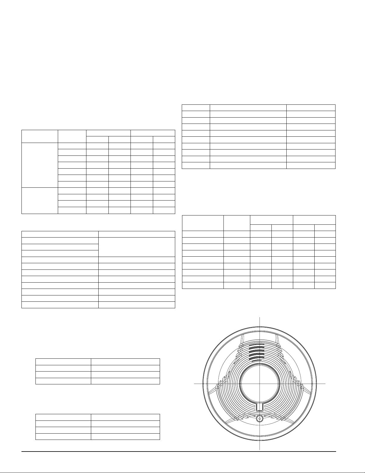
NOTE: Ceiling products have their maximum brightness on
the two axes shown below.
Table 3. Horizontal Plane Light Distribution for
Wall and Ceiling Applications
Horizontal Angle % of rated light output
0 100
45 75
90 25
Table 4. Vertical Plane Light Distribution
for Wall Applications
Vertical Angle % of rated light output
0 100
45 34
90 12
D690-03-00 2 I56-2769-003R
A0351-00
Page 3

Table 7. 2-wire Horn/Strobe Standard Candela Range (15–115 cd) Current Draw (mA)
Horn
(+)
(–)
(+)
(–)
E
O
L
(+)
(–)
(+)
(–)
Horn/strobe
Strobe Only
Two Wire System
Any Mix of Models
Wired for Tandem
Operation
Horn
(+)
(–)
(+)
(–)
E
O
L
(+)
(–)
(+)
(–)
Horn/strobe
Strobe Only
Two Wire System
Any Mix of Models
Wired for Tandem
Operation
Horn
Synchronization Module
(+)
(–)
(+)
(–)
E
O
L
(+)
(–)
(+)
(–)
Horn/strobe
Strobe Only
Two Wire System
Any Mix of Models
Wired for Tandem
Operation
MDL
(+)
(–)
(+)
(–)
(+)
(–)
FOUR WIRE SYSTEM
COMBO MODELS
WIRED FOR INDEPENDENT
OPERATION
(HORN CAN BE TURNED OFF
AT THE PANEL WHILE STROBES
CONTINUE TO OPERATE)
E
O
L
(+)
(–)
(+)
(–)
(+)
(–)
E
O
L
S
T
R
O
B
E
C
O
M
B
O
H
O
R
N
H
O
R
N
S
T
R
O
B
E
8–17.5 Volts 16–33 Volts
DC Input
15 15/75 15 15/75 30 75 95 110 115
Temporal High 137 147 79 90 107 176 194 212 218
Temporal Medium 132 144 69 80 97 157 182 201 210
Temporal Low 132 143 66 77 93 154 179 198 207
Non-temporal High 141 152 91 100 116 176 201 221 229
Non-temporal Medium 133 145 75 85 102 163 187 207 216
Non-temporal Low 131 144 68 79 96 156 182 201 210
FWR Input
Temporal High 136 155 88 97 112 168 190 210 218
Temporal Medium 129 152 78 88 103 160 184 202 206
Temporal Low 129 151 76 86 101 160 184 194 201
Non-temporal High 142 161 103 112 126 181 203 221 229
Non-temporal Medium 134 155 85 95 110 166 189 208 216
Non-temporal Low 132 154 80 90 105 161 184 202 211
Table 8. 2-wire Horn/Strobe High Candela Range (135–185 cd) Current Draw (mA)
DC Input
Temporal High
Temporal Medium
Temporal Low
Non-temporal High
Non-temporal Medium
Non-temporal Low
16–33 Volts
135 150 177 185 135 150 177 185
245 259 290 297
235 253 288 297
232 251 282 292
255 270 303 309
242 259 293 299
238 254 291 295
FWR Input
Temporal High
Temporal Medium
Temporal Low
Non-temporal High
Non-temporal Medium
Non-temporal Low
215 231 258 265
209 224 250 258
207 221 248 256
233 248 275 281
219 232 262 267
214 229 256 262
16–33 Volts
Table 9. Horn & Horn/Strobe Output (dBA)
Figure 3. Any combination of models powered by a
4-wire circuit
Switch
Position
1 Temporal High 78 78 84 84
2 Temporal Medium 74 74 80 80
3 Temporal Low 71 73 76 76
4 Non-temporal High 82 82 88 88
5 Non-temporal Medium 78 78 85 85
6 Non-temporal Low 75 75 81 81
7* Coded High 82 82 88 88
8* Coded Medium 78 78 85 85
9* Coded Low 75 75 81 81
*Horn & 4-wire Horn/Strobe only
Sound
Pattern dB
8–17.5 Volts 16–33 Volts
DC FWR DC FWR
Wiring
Figure 1. Non-Synchronized devices; any combination
of models powered by a 2-wire circuit
A0113-00
Figure 2. Synchronized devices; any combination of
models powered by a 2-wire circuit
NOTE: For further information on synchronization see
MDL, panel, or power supply installation manual.
D690-03-00 3 I56-2769-003R
A0111-01
Terminal Definitions
Figure 4. Figure 5.
A0350-00
P2, PC2, S, SC, & H Series P4 & PC4 Series
A0352-00
Page 4
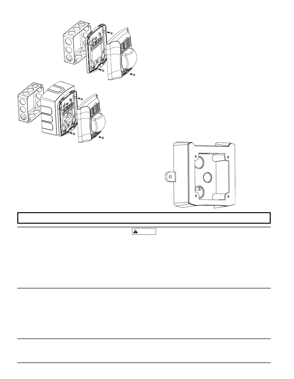
Mounting
WARNING
Figure 6.
Figure 7.
Back box skirt
model numbers:
BBS-2, BBSW-2,
BBSC-2, and BBSCW-2
A0348-00
installed using the proper SpectrAlert Advance watertight junction box. The wall mount watertight junction
box must be mounted with its internal post in the lower
left corner as shown in Figure 8.
2. Connect field wiring according to terminal definitions.
3. If the product is not to be installed at this point, use the
dust cover to prevent contamination of the wiring terminals of the mounting plate.
4. To attach product to mounting plate, hook tabs on the
product housing into the grooves on mounting plate.
Then, swing product into position to engage the pins on
the product with the terminals on the mounting plate.
Make sure that the tabs on the back of the product housing fully engage with the mounting plate.
5. Secure product by tightening the single mounting screw
in the front of the product housing.
NOTE: Standard captured mounting screw may be re-
placed with enclosed torx screw for tamper resistance.
A0349-00
Figure 8.
Mounting (Wall or Ceiling)
1. Attach mounting plate to junction box as shown in Figure 6. The mounting plate is compatible with 4˝ square,
double gang, and 4˝ octagon junction boxes (2-wire
products may be used with a single gang box). If using
a back box skirt, attach the mounting plate to the skirt
and then attach the entire assembly to the junction box
(see Figure 7).
NOTE: For outdoor applications, the product must be
Please refer to insert for the Limitations of Fire Alarm Systems
The Limitations of Horn/Strobes
The horn and/or strobe will not work without power. The horn/strobe gets its
power from the fire/security panel monitoring the alarm system. If power is cut off
for any reason, the horn/strobe will not provide the desired audio or visual warning.
The horn may not be heard. The loudness of the horn meets (or exceeds) current
Underwriters Laboratories’ standards. However, the horn may not alert a sound
sleeper or one who has recently used drugs or has been drinking alcoholic bever
ages. The horn may not be heard if it is placed on a different floor from the person
in hazard or if placed too far away to be heard over the ambient noise such as traffic,
air conditioners, machinery or music appliances that may prevent alert persons from
hearing the alarm. The horn may not be heard by persons who are hearing impaired.
NOTE: Strobes must be powered continuously for horn operation.
Three-Year Limited Warranty
Syst em Sens or wa rra nts its encl osed product to be free from defects in materials a nd wor kmans hip unde r normal use and s ervic e for a pe riod of t hree
years from dat e of ma nufac ture. System S ensor makes no oth er express war
ranty for this product. No agent, representat ive, dealer, or employee of the
Company has t he aut hority to increas e or al ter th e obligations or lim itations
of this Warranty. The Company’s o bligati on o f this Warran ty sha ll b e li mited
to the repl acement of a ny p art of the pro duct w hich i s foun d to be def ective
in m ateri als or wo rkman ship und er norma l use and se rvice du ring the three
year per iod com mencing with the d ate of ma nufacture. Af ter pho ning Syste m
Sensor’s toll f ree nu mber 800 -SENSOR2 (736 -7672) f or a Return Auth oriza tion
number, sen d defect ive un its post age prepaid to: System S ensor, Retu rns
FCC Statement
SpectrAlert Strobes and Horn/Strobes have been tested and found to comply with the
limits for a Class B digital device, pursuant to part 15 of the FCC Rules. These limits
are designed to provide reasonable protection against harmful interference when the
equipment is operated in a commercial environment. This equipment generates, uses,
D690-03-00 4 I56-2769-003R
©2006 System Sensor
The signal strobe may not be seen. The electronic visual warning signal uses an extremely
reliable xenon flash tube. It flashes at least once every second. The strobe must not be in
stalled in direct sunlight or areas of high light intensity (over 60 foot candles) where the visual
flash might be disregarded or not seen. The strobe may not be seen by the visually impaired.
The signal strobe may cause seizures. Individuals who have positive photoic response
to visual stimuli with seizures, such as persons with epilepsy, should avoid prolonged
exposure to environments in which strobe signals, including this strobe, are activated.
The signal strobe cannot operate from coded power supplies. Coded power supplies
produce interrupted power. The strobe must have an uninterrupted source of power in order
to operate correctly. System Sensor recommends that the horn and signal strobe always
be used in combination so that the risks from any of the above limitations are minimized.
Departme nt, RA #____ ______, 3825 O hio Avenue, St. Charl es, IL 60174. Please
include a note descr ibing the malfuncti on and suspe cted cause of failu re.
-
The Compa ny sha ll not be oblig ated to replac e unit s w hich a re fou nd to be
defective be cause of d amage, unreasonab le use, modif icati ons, or al terations
occurrin g after the date of manufa cture. In no case shall the Company be
liable for any co nsequen tial or incid ental dama ges for bre ach o f t his o r a ny
other Warran ty, ex pre ssed o r impl ied whatsoever, eve n if the lo ss o r dama ge
is cause d by the Com pany’s negligen ce or f ault. S ome sta tes do not all ow th e
excl usion or limit ation of incidental or con sequent ial da mages, so th e above
limitati on or excl usion may no t apply t o yo u. This Warran ty gives you spe cific
legal rights, an d yo u may al so have other rig hts wh ich vary from sta te to state.
and can radiate radio frequency energy and, if not installed and used in accordance
with the instruction manual, may cause harmful interference to radio communications.
Operation of this equipment in a residential area is likely to cause harmful interference
in which case the user will be required to correct the interference at his own expense.
A0354-00
-
 Loading...