

Page 1
INSTALLATION AND MAINTENANCE INSTRUCTIONS
1
/2 Sec.
On
1
/2 Sec.
Off
1
/2 Sec.
On
1
/2 Sec.
Off
1
/2 Sec.
On
11/2 Sec.
Off
Repeats
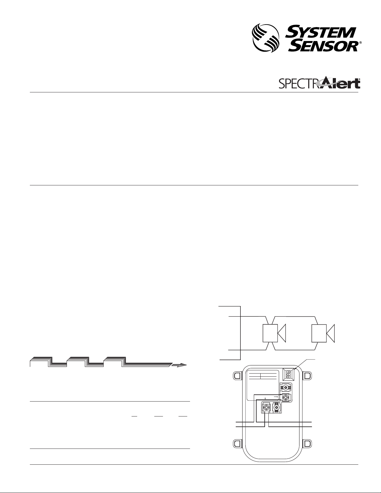
DIP SWITCH
NOTE: VOLUME SWITCH
DOES NOT OPERATE
TO NEXT DEVICE
FROM AC SOURCE
AC POWER
NOT USED
TEMPORAL NON-TEMPORAL
EM 3kHz
OFF ON
1
O N
2 3
STROBE (–)
MODULE (–)
STROBE (+)
MODULE (+)
HORN/STROBE
120 VAC
POWER
3825 Ohio Avenue, St. Charles, Illinois 60174
SpectrAlert Outdoor Horn/Strobe
For use with model: P12015K
1-800-SENSOR2, FAX: 630-377-6495
www.systemsensor.com
The Products to which this manual applies may be covered by one or more of the
following U.S. Patent numbers:
5,914,665; 5,850,178; 5,598,139; 6,049,446; 5,593,569; 6,133,843
Specifications
Rated Voltage: Regulated 120 VAC
Operating Voltage Limits: 96-132 VAC
NOTE: Combo units will operate on walk tests with on-time durations of 1 sec. or greater.
Flash Rate: 1 Flash Per Second
Operating Temperature: Horn/Strobes have a temperature range of -40°F to 150°F (-40°C to 66°C) and are rainproof per UL50
(NEMA 3R).
Horns are indoor/outdoor listed per UL464.
Strobes are indoor/outdoor listed per UL1638.
Light Output: Listed at 15 candela (2.78cd @ -40°C).
Sound Output: Sound output levels are established at Underwriters Laboratories in their reverberant room. Always use
the sound output specified as UL Reverberant Room when comparing products.
Listings: UL S4011 and S3593
General Description
The SpectrAlert series notification appliances are designed to
meet the requirements of most agencies governing these devices,
including: NFPA, The National Fire Alarm Code, UL, CSFM, MEA.
Also, check with your local Authority Having Jurisdiction for other
codes or standards that may apply.
Horn Selections
Horns are factory set for temporal code and electromechanical
tone.
Tones:
Two tones may be selected using the DIP switch (see Figure 1)
located on the printed circuit board. With the switch off, the
tone is the Electromechanical sound. With the switch on, the
The P12015K must be installed using a 120 VAC power source. This
unit can only be used for non-synchronous applications. This unit
will NOT work with SpectrAlert Sync•Circuit Modules.
tone is a 3 kHz sound.
Temp/Non-Temp:
Temporal coding or Non-Temporal coding can be selected
using the DIP switch located on the printed circuit board.
NOTICE: This manual shall be left with the owner/user of this
equipment.
With the switch off, the tone pattern is the Temporal
Coded Signal. With the switch on, the Non-Temporal
code (continuous) tone is active.
Fire Alarm System Considerations
Temporal and Non-Temporal Coded Signals:
The American National Standards Institute and the National
Fire Alarm Code require that all horns used for building evacuation installed after July 1, 1996, must produce Temporal Coded
System Operation
Figure 1 (Note: power inputs are non-polarized):
A0239-00
Signals.
Signals other than those used for evacuation purposes do not have
to produce the Temporal Coded Signal. Temporal coding is accomplished by interrupting a steady sound in the following manner:
Current Draw Measurements – Both Horn and Strobe
Maximum Current Limit: 261.6mA RMS (as measured by UL)
Sound Output Guide UL Reverberant Room dBA@ Volts AC RMS
96 120 132
Temporal Electromechanical 78 78 78
3000 Hz Interrupted 79 79 79
Non-Temporal Electromechanical 83 83 83
3000 Hz Interrupted 84 84 84
D900-26-00 1 I56-1792-002R
A0240-00
Page 2
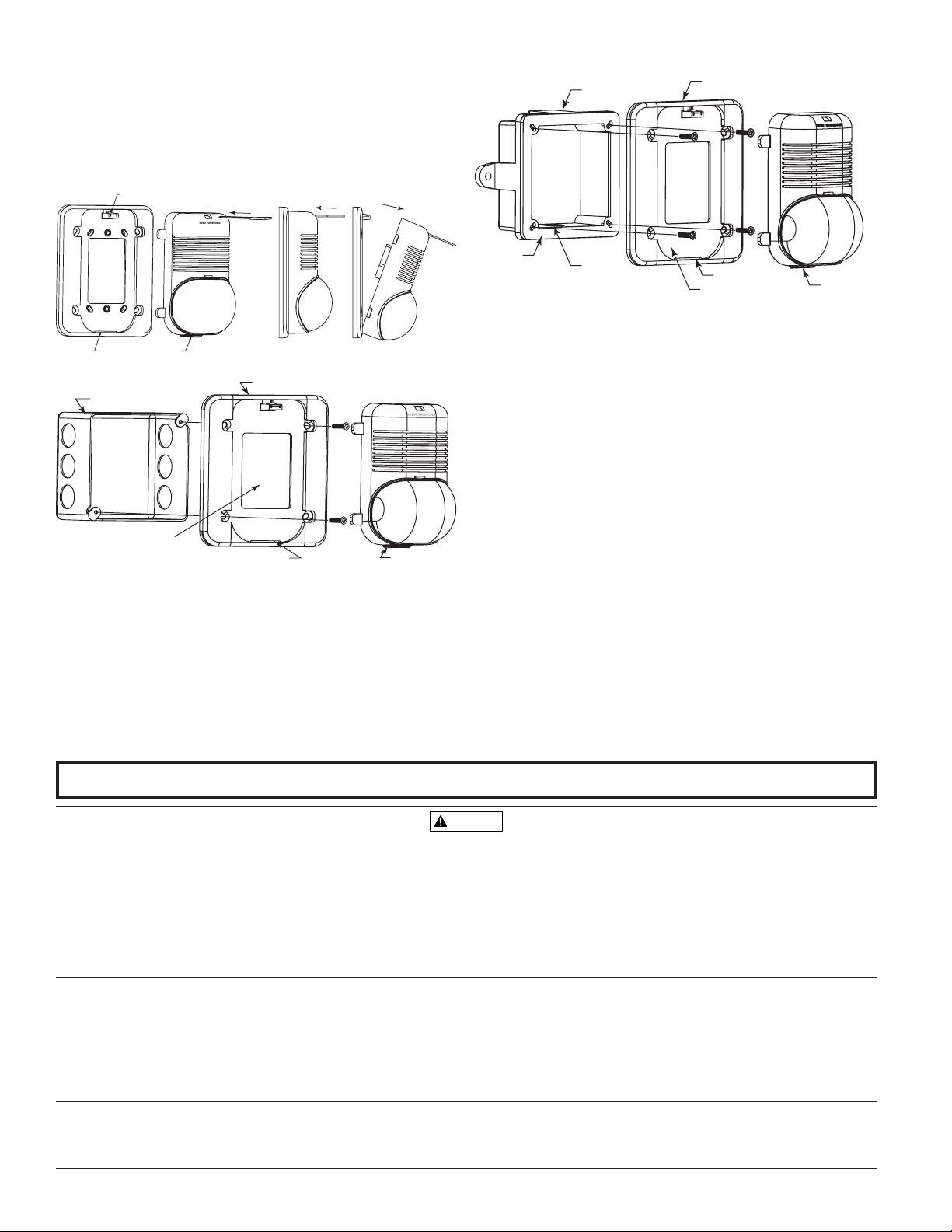
4-INCH BACK BOX
WALL OPENING MUST
EQUAL PLATE OPENING
LOCKING RIB SLOT
LOCKING RIB
D-MP
A
A
WARNING
PLASTIC SNAP LEVER
TAB SLOT
TAB
INSERT REMOVAL TOOL
Figure 2: Removal of horns and strobes from mounting
WBB
Gasket
Plate
Paper Liner For
Plate Gasket
Conduit
Entrance
Slot
Locking Rib
plates:
To remove units from mounting plates, insert Quick Click Removal
Tool as shown to unlock snap. While pushing in Removal Tool to
release the snap, pull back on the horn/strobe. Hinge the horn/
strobe module, disengage the Locking Rib, and lift the horn/
strobe away from the mounting plate.
A0242-00
Figure 4: Indoor Horn/Strobe mounting with universal plate:
Figure 3: Outdoor Horn/Strobe mounting with universal plate:
A0241-00
1. Mount plate to back box using 4 screws (Figure 3).
2. Complete field wiring.
NOTE: Perform electrical tests first, then remove paper liner.
3. Remove liner – WARNING! Paper liner must be removed from gasket
before final installation.
4. Insert locking rib into slot on plate.
5. Press into plate, unit will make a “click” when it has locked into
place.
Note: The outdoor horn/strobe must be used with a WBB back box
when installed in applications requiring the outdoor horn/strobe to
be rainproof. In such applications, using a back box other than the
WBB will void the rainproof per UL50 designation.
A0243-00
1. Mount plate to back box using 2 screws, making sure wall opening is
equal to the plate opening.
2. Complete field wiring.
NOTE: Perform electrical tests first, then remove liner.
3. Remove liner – WARNING! Liner must be removed from gasket
before final installation.
4. Insert locking rib into slot on plate.
5. Press into plate, unit will make a “click” when it has locked into place.
Please refer to insert for the Limitations of Fire Alarm Systems
The Limitations of Horn/Strobes
The horn and/or strobe will not work without power. The horn/strobe gets its power from the
fire/security panel monitoring the alarm system. If power is cut off for any reason, the horn/strobe
will not provide the desired audio or visual warning.
The horn may not be heard. The loudness of the horn meets (or exceeds) current Underwriters
Laboratories’ standards. However, the horn may not alert a sound sleeper or one who has recently
used drugs or has been drinking alcoholic beverages. The horn may not be heard if it is placed on a
different floor from the person in hazard or if placed too far away to be heard over the ambient noise
such as traffic, air conditioners, machinery or music appliances that may prevent alert persons from
hearing the alarm. The horn may not be heard by persons who are hearing impaired.
The signal strobe may not be seen. The electronic visual warning signal uses an extremely reliable
System Sensor warrants its enclosed horn, strobe or horn/strobe to be free from defects in materials
and workmanship under normal use and service for a period of three years from date of manufacture. System Sensor makes no other express warranty for this horn, strobe or horn/strobe. No agent,
representative, dealer, or employee of the Company has the authority to increase or alter the obligations or limitations of this Warranty. The Company’s obligation of this Warranty shall be limited
to the replacement of any part of the horn, strobe or horn/strobe which is found to be defective in
materials or workmanship under normal use and service during the three year period commencing
with the date of manufacture. After phoning System Sensor’s toll free number 800-SENSOR2 (736-
7672) for a Return Authorization number, send defective units postage prepaid to: System Sensor,
SpectrAlert Horn/Strobes have been tested and found to comply with the limits for a Class B digital
device, pursuant to part 15 of the FCC Rules. These limits are designed to provide reasonable pro
tection against harmful interference when the equipment is operated in a commercial environment.
D900-26-00 2 I56-1792-002R
© 2002 System Sensor
Three-Year Limited Warranty
xenon flash tube. It flashes at least once every second. The strobe must not be installed in direct
sunlight or areas of high light intensity (over 60 foot candles) where the visual flash might be disregarded or not seen. The strobe may not be seen by the visually impaired.
The signal strobe may cause seizures. Individuals who have positive photoic response to visual
stimuli with seizures, such as persons with epilepsy, should avoid prolonged exposure to environments in which strobe signals, including this strobe, are activated.
The signal strobe cannot operate from coded power supplies. Coded power supplies produce
interrupted power. The strobe must have an uninterrupted source of power in order to operate correctly. System Sensor recommends that the horn and signal strobe always be used in combination
so that the risks from any of the above limitations are minimized.
Returns Department, RA #__________, 3825 Ohio Avenue, St. Charles, IL 60174. Please include a
note describing the malfunction and suspected cause of failure. The Company shall not be obligated
to repair or replace units which are found to be defective because of damage, unreasonable use,
modifications, or alterations occurring after the date of manufacture. In no case shall the Company
be liable for any consequential or incidental damages for breach of this or any other Warranty,
expressed or implied whatsoever, even if the loss or damage is caused by the Company’s negligence
or fault. Some states do not allow the exclusion or limitation of incidental or consequential damages, so the above limitation or exclusion may not apply to you. This Warranty gives you specific
legal rights, and you may also have other rights which vary from state to state.
FCC Statement
This equipment generates, uses, and can radiate radio frequency energy and, if not installed and
-
used in accordance with the instruction manual, may cause harmful interference to radio communications. Operation of this equipment in a residential area is likely to cause harmful interference
in which case the user will be required to correct the interference at his own expense.
 Loading...