

Page 1
INSTALLATION AND MAINTENANCE INSTRUCTIONS
CAUTION
OSYEXP Explosion Proof
Gate Valve Supervisory Switch
Specifications
Contact Ratings: One SPDT (Form C) Switch
15 A @ 125/250/480 VAC; 1/8 HP @ 125 VAC, 1/4 HP @ 250 VAC
1/2 A @ 125 VDC; 1/4 A @ 250 VDC
Dimensions: 7″L X 3.125″D X 4.875″H
Maximum Stem Extension: 2.875″
Bracket Span: 7″
Operating Temperature Range: –40° - 160°F (–40°C – 71°C)
Shipping Weight: 2-1/4 lb.
Enclosure Rating: UL Listed explosion proof switch enclosure for use in hazardous locations.
Class I, Groups C and D; Class II, Groups E. F and G
Important
Please Read Carefully And Save
This manual contains important information about the
installation and operation of supervisory switches. These
instructions apply to System Sensor switches for outside
screw and yoke valves only. Read all instructions carefully
before beginning installation.
To prevent ignition of hazardous atmospheres, disconnect
supply circuit before opening. Keep assembly tightly closed
when in operation. Do NOT leave unused wires exposed.
All supervisory switch installations must comply with local
codes and ordinances and the requirements of the authority having jurisdiction. Additional information is available
in National Fire Protection Association standards NFPA 13,
13D, 13R, 71, and 72.
General Installation Considerations
The OSYEXP Supervisory Switch can be mounted on open
yoke valves between 1/2″ and 12″ in diameter. The switch
is designed to supervise the open condition of the OS & Y
Gate Valve in hazardous locations.
All OSYEXP models are equipped with a ground screw
inside the switch housing for those applications where
grounding is required.
Narrow Yoke Valves
As Figure 1 suggests, installing the valve with mounting
bolts inside the yoke is recommended. However, some
valves may have yokes that are too narrow for this arrangement. If this is the case, the bolts can be positioned on the
outside of the yoke.
Limited Clearance Valves
The OSYEXP mounting bracket fits most of the open yoke
valves used in fire protection systems. However, some of
these valves, especially those less than 11/2″ in diameter,
have irregularly shaped yokes or such limited clearances
that the clamping bar cannot be installed properly and/or
it causes the valve to bind. If this is the case, the use of
the supplied J-bolts is required to attach the OSYEXP to the
valve (see J-Bolt Detail, Figure 1).
Installation Procedure
See Figures 2 and 3, as required, while performing the procedure that follows.
Perform step 1 on valves 11/2″ in diameter and smaller
only. Proceed directly to step 2 if the switch is being
installed on a valve larger than 11/2″ in diameter.
1. Remove and discard the two C-clips and roller from the
actuating lever.
2. Set the valve to its fully open position. Remove the
OSYEXP Supervisory Switch from the carton and adjust
the position of the retaining washers to provide sufficient bolt length for the yoke thickness of the valve.
3825 Ohio Avenue, St. Charles, Illinois 60174
1-800-SENSOR2, FAX: 630-377-6495
www.systemsensor.com
D770-27-00 1 I56-1429-002R
Page 2
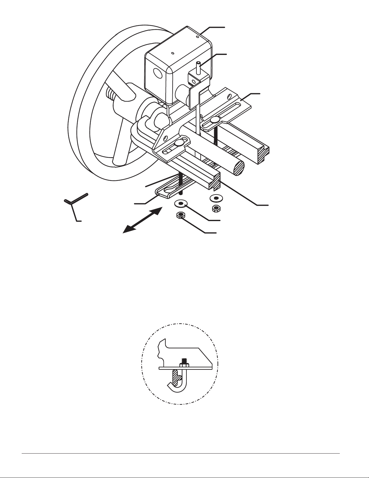
Figure 1:
Switch Housing
Actuating Lever
Mounting Bracket
Yoke
Retaining Washer
Nut
Hex Wrench
Clamping Bar
Carriage Bolt
Slide Clamping
Bar to remove
or install
W0182-00
J-Bolt Detail:
NOTE:
Larger gate valve shown (2″ through 12″). When installing supervisory switch to smaller gate valves (1/2″ through
11/2″), carriage bolts are to be located on outboard side of
yoke. On small valves with limited clearance, J-bolts may
be used.
W0207-00
D770-27-00 2 I56-1429-002R
Page 3

YOKE
GROOVE
CLAMPING BAR NOT SHOWN
THREADED VALVE
GLAND HEX NUT
OR BOLT
VALVE
STEM
GLAND
STEM HEX
Figure 2: 6. Mount the switch loosely with the actuating lever cen-
tered in the groove. When the switch is in position on
the valve, slide the open end of the clamping bar onto
the bolts and under the retaining washers, as indicated
in Figure 1.
7. Ensure that the actuating lever does not hit the clamping
bar at any point in its travel. If it does, adjust the length
of the lever by loosening the lever screw, sliding the
lever in or out, as needed, and retightening the screw.
8. Adjust the supervisory switch position on the valve so
that the switch is open when the actuating lever is in
W0209-00
the groove with the valve in the full open position. The
circuit should close when the valve is closed 1/5 of its
Position the switch on the valve with the bolts on the
inside (preferably) or outside of the yoke, depending on
clearances. Adjust the position of the OSYEXP as far as
possible from the valve gland and in a location where
the actuating lever contacts the unthreaded section of
the valve stem (if the valve stem is already grooved,
proceed directly to step 6).
3. When the switch is in position on the valve, slide the
open end of the clamping bar onto the bolts and under
the retaining washers. If necessary, adjust the length of
the actuating lever by loosening the lever screw. The
lever is properly adjusted when it clears the clamping
bar. Tighten the nuts by hand and slide the OSYEXP until
the switch trip point is found as the lever rests on the
valve stem. This approximates the final position of the
OSYEXP after the valve stem is grooved. Carefully check
all clearances of the bolts, actuator, mounting bracket,
travel or 2 full turns of the handle, whichever is less. The
switch produces an audible “click” when it closes. The
switch closure can also be tested electrically by using an
ohmmeter to test for continuity between its terminals.
9. Tighten the nuts securely with a wrench and check
the operation of the OSYEXP as in step 8. If necessary,
reposition the OSYEXP and test it again.
10. Wire the supervisory switch as shown in Figure 3.
NOTE: When removing the cover of the OSYEXP use
provided allen wrench in box.
11. Replace the OSYEXP cover.
12. Test the operation of the OSYEXP by closing the valve
the 1/5 of its travel distance or two full turns, whichever
is less. The circuit should indicate a closure during
this procedure. If it does not, readjust the supervisory
switch and actuator positions until the switch closes
when the valve is operated.
clamping bar, and OSYEXP cover. Adjust the position as
necessary. If clearance is a problem, refer to the Limited
Clearance Valves (page 1) section of this manual.
4. Mark the point on the valve stem where the actuating
lever contacts the valve stem.
Testing
Test the operation of all supervisory switches before they
are placed into service and at least semiannually, or as
required by the authority having jurisdiction.
5. Remove the OSYEXP by loosening the nuts and sliding
the clamping bar from beneath the retaining washers.
Remove the OSYEXP from the valve and set it aside.
(a) Valves 11/2″ in diameter and smaller only.
Use a 1/2″ untapered round file to file a groove 3/32″ deep
in the valve stem at the mark that was made in step 4.
NOTE: Notify the proper authorities that the supervi-
sory switch(es) is (are) undergoing maintenance
and, therefore, will be temporarily out of service.
Disable the system or zone undergoing testing to
prevent unwanted alarms.
Be sure to remove any burrs resulting from the filing
to avoid damaging the valve stem packing gland.
(b) Valves larger than 11/2″ inches in diameter only.
Use a 3/8″ untapered round file to file a groove 1/8″ deep
in the valve stem at the mark that was made in step 4.
Be sure to remove any burrs resulting from the filing
to avoid damaging the valve stem packing gland.
Test the operation of the OSYEXP by closing the valve the
1
/5 of its total travel distance or two full turns, whichever is
less. A contact closure must occur during this procedure.
If it does not, readjust the supervisory switch and actuator
positions until the switch closes when the valve operated.
D770-27-00 3 I56-1429-002R
Page 4

WARNING
Figure 3. Supervisory switch wiring diagram:
To power source
compatible with bell
Local
Bell
COM
NO
NC
Typical Local Bell Connection
COM
NO
NC
COM
NO
NC
Sup. Switch
Sup. Switch
Typical Facp Connection
End of Line
resistor
To non-silenceable
intiating zone of
listed FACP
W0239-00
W0240-00 W0241-00
1. Alarms generated by the actuation of the activating lever
may not be received by a central station if telephone or
other communication lines to the detector are out of
service, disabled, or open.
2. Supervisory switch alarm devices have a normal service
life of 10-15 years.
System Sensor warrants its enclosed pressure switch to be free from
defects in materials and workmanship under normal use and service for a
period of three years from date of manufacture. System Sensor makes no
other express warranty for this pressure switch. No agent, representative,
dealer, or employee of the Company has the authority to increase or alter
the obligations or limitations of this Warranty. The Company’s obliga
tion of this Warranty shall be limited to the repair or replacement of any
part of the pressure switch which is found to be defective in materials or
workmanship under normal use and service during the three year period
commencing with the date of manufacture. After phoning System Sensor’s
toll free number 800-SENSOR2 (736-7672) for a Return Authorization
number, send defective units postage prepaid to: System Sensor,
D770-27-00 4 I56-1429-002R
Break wire as shown for supervision of
connection. DO NOT allow stripped wire
leads to extend beyond switch housing.
DO NOT loop wires.
The Limitations of Supervisory Switch Alarm Devices
3. Supervisory switches are not a substitute for insurance.
Building owners should always insure property and lives
being protected.
Please refer to insert for the Limitations of Fire Alarm Systems
Three-Year Limited Warranty
Department, RA #__________, 3825 Ohio Avenue, St. Charles, IL 60174.
Please include a note describing the malfunction and suspected cause
of failure. The Company shall not be obligated to repair or replace units
Return
which are found to be defective because of damage, unreasonable use,
modifications, or alterations occurring after the date of manufacture. In
-
no case shall the Company be liable for any consequential or incidental
damages for breach of this or any other Warranty, expressed or implied
whatsoever, even if the loss or damage is caused by the Company’s neg
ligence or fault. Some states do not allow the exclusion or limitation of
incidental or consequential damages, so the above limitation or exclusion
may not apply to you. This Warranty gives you specific legal rights, and
you may also have other rights which vary from state to state.
©
-
System Sensor 2005
 Loading...