

Page 1
INSTALLATION AND MAINTENANCE INSTRUCTIONS
+2
-1
+2
-1
+2
-1
+2
-1
2 COMM +
1 COMM -
+2
-1
+2
-1
+2
-1
+2
-1
3825 Ohio Avenue, St. Charles, Illinois 60174
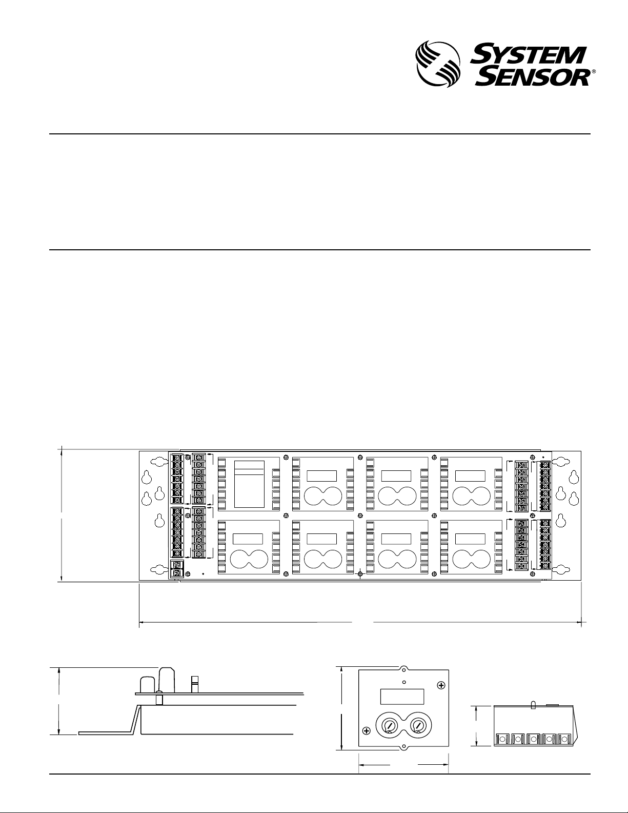
MB500 Module Panel
1-800-SENSOR2, FAX: 630-377-6495
Specifications
PANEL (Figures 1A and 1B) MODULE (sold separately; Figure 1C)
Depth: 2.17 inches (5.51 cm) Depth: 1.50 inches (3.81 cm)
Height: 6.13 inches (15.57 cm) Height: 2.70 inches (6.86 cm)
Width: 20.18 inches (51.26 cm) Width: 2.82 inches (7.16 cm)
Operating Temperature Range: 32° to 120°F (0° to 49°C)
Operating Humidity Range: 10% to 93% relative humidity, noncondensing
Construction of Bracket: 16-gauge galvanized steel
A Division of Pittway
NOTICE: This manual should be left with the owner/user
of this equipment.
General Description
Before installing this module panel, please thoroughly read
the system wiring and installation manuals. Also be aware
of the appropriate local and national standards and codes
of practice for the placement and installation of control
panels.
The MB500 Module Panel is for use with any listed enclosure suitable for fire-protection signaling applications. It
Figure 1A. MB500 module panel:
AB
9
DISCONNECT ALL POWER SOURCES
C = CONTROLM = MONITOR
MODULE TYPE ADDRESS
8
A C M ______
B C M ______
C C M ______
D C M ______
7
E C M ______
F C M ______
G C M ______
6
H C M ______
ALL MODULES MUST BE USED FOR
EITHER POWER - LIMITED OR
NON - POWER LIMITED APPLICATIONS. NO COMBINATION IS
ALLOWED.
5
WARNING
BEFORE SERVICING
-1
+2
3
4
9
8
7
6
5
E
9
8
7
3
6
2
1
5
-1
+2
54
4
5
6
3
6
3
7
7
2
8
8
1
0 9
0 9
E
4
9
8
7
6
5
6.13
9
8
M
O
7
D
U
6
L
E
5
A
4
3
9
M
8
O
7
D
U
6
L
E
5
E
4
3
2 COMM +
1 COMM -
9
8
M
O
7
D
U
6
L
E
5
B
4
3
9
8
M
O
7
D
U
6
L
E
5
F
4
3
provides a platform for the installation of up to 8 (two rows
of 4) standard monitor and/or control modules. Wiring and
mounting requirements of the modules are reduced by using the MB500.
The MB500 will support any combination of monitor and
control modules on one panel, but a combination of powerlimited and nonpower-limited modules is NOT permitted.
The monitor and control modules used with the MB500
meet the same electrical specifications as the individual
M500MB, M500CH, and M502M.
C
9
-1
+2
54
5
4
6
3
6
3
2
1
0 9
3
7
2
7
8
1
8
0 9
B
4
8
7
3
6
2
1
5
F
-1
+2
54
5
4
6
3
6
3
7
2
7
8
1
8
0 9
0 9
C
4
GH
9
-1
+2
54
5
4
6
3
6
3
2
1
0 9
3
7
2
7
8
1
8
0 9
F
4
8
7
3
6
2
1
5
-1
+2
54
4
5
6
3
6
3
7
7
2
8
8
1
0 9
0 9
G
4
D
9
8
7
5
4
3
6
3
6
2
7
2
1
8
1
0 9
0 9
D
5
9
8
7
5
4
3
6
3
6
2
7
2
1
8
1
0 9
0 9
H
5
9
9
8
8
M
-1
+2
54
6
3
7
8
4
-1
+2
54
6
3
7
8
4
M
O
O
7
7
D
D
U
U
6
6
L
L
E
E
5
5
C
D
4
4
3
3
9
9
8
8
M
M
O
O
7
7
D
D
U
U
6
6
L
L
E
E
5
5
G
H
4
4
3
3
20.18
A78-2621-00
Figure 1B. MB500 module panel height:
Figure 1C. Module dimensions:
2.17
2.7
4
3
2
1
0 9
A78-2622-00
D500-35-00 1 I56-917-02
5
6
7
8
2.82
54
3
6
7
2
8
1
0 9
1.50
9
8765
A78-2623-00
Page 2
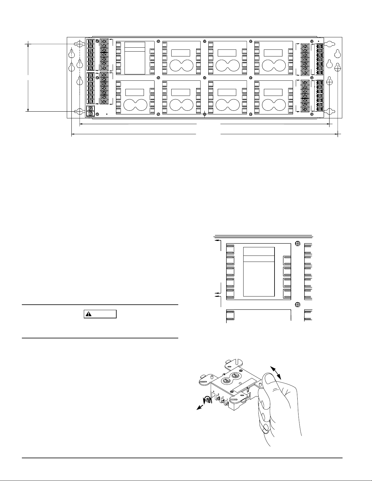
Figure 2. Mounting holes:
A
WARNING
DISCONNECT ALL POWER SOURCES
9
BEFORE SERVICING
C = CONTROLM = MONITOR
MODULE TYPE ADDRESS
8
A C M ______
B C M ______
C C M ______
D C M ______
7
E C M ______
F C M ______
G C M ______
6
H C M ______
ALL MODULES MUST BE USED FOR
EITHER POWER - LIMITED OR
NON - POWER LIMITED APPLICATIONS. NO COMBINATION IS
5
ALLOWED.
-1
+2
3
4
9
8
7
3
6
2
1
5
EF
9
8
7
3
6
2
1
5
-1
+2
4
5
54
6
6
3
3
7
2
7
8 1
8
0 9
0 9
E
4
9
8
7
3
6
2
1
5
5.000 (C)
9
8
M
O
7
D
U
6
L
E
5
4
3
9
M
8
O
7
D
U
6
L
E
5
E
4
3
2 COMM +
1 COMM -
9
8
M
O
7
D
U
6
L
E
5
BA
4
3
9
8
M
O
7
D
U
6
L
E
5
F
4
3
Mounting
1) Select the desired mounting location in a cabinet and
measure the mounting hole centers. The MB500 is
equipped with 3 sets of mounting holes for use depending on the mounting configuration:
A) 19 inch EIA standard with 18.312 inch (46.5 cm) cen-
ter-to-center mounting holes for horizontal mounting
B) 19.5 inch (49.5 cm) center-to-center mounting holes
for horizontal mounting
C) 5 inch (12.7 cm) center-to-center mounting holes for
vertical mounting
2) Hold the MB500 in place, mark the appropriate set of
mounting holes, and drill holes (if needed) in the
mounting surface.
3) Drive screws in place, allowing room for the MB500 to
slide over the screw heads.
4) Tighten screws to secure the MB500 to the mounting
surface.
WARNING
Remove power before installing modules and wiring the
MB500 panel.
Address Verification
Before installing the modules onto the panel, use the label
in position A (see Figure 3A) to record the type for each
module. Circle C (control) or M (monitor) to indicate the
type of module and record the address on the space provided.
B
-1
+2
4
5
54
6
6
3
3
7
2
7
8 1
8
0 9
0 9
B
4
-1
+2
4
5
54
6
6
3
3
7
2
7
8 1
8
0 9
0 9
F G
4
C
9
8
7
3
6
2
1
5
-1
+2
4
5
54
6
6
3
3
7
2
7
8 1
8
0 9
0 9
C
4
G
9
8
7
3
6
2
1
5
-1
+2
4
5
54
6
6
3
3
7
2
7
8 1
8
0 9
0 9
4
D
9
8
7
4
5
3
6
3
6
2
7
2
1
8 1
0 9
0 9
5
D
H
9
8
7
4
5
3
6
3
6
2
7
2
1
8 1
0 9
0 9
5
H
9
9
8
M
8
-1
+2
54
6
3
7
8
4
-1
+2
54
6
3
7
8
4
M
O
O
7
7
D
D
U
U
6
6
L
L
E
E
5
5
C
D
4
4
3
3
9
9
8
8
M
M
O
O
7
7
D
D
U
U
6
6
L
L
E
E
5
5
G
H
4
4
3
3
18.312 (A)
19.500 (B)
A78-2624-00
circuit board of the MB500 with the terminals on the individual modules, and plug a module into the panel at position A (see Figure 4). Repeat the procedure for positions B,
C, and so on, for up to 8 modules.
Figure 3A. Label each module:
9
8
7
6
5
4
9
M
O
D
8
U
L
E
7
B
6
3
5
9
8
M
O
7
9
D
U
A
WARNING
DISCONNECT ALL POWER SOURCES
BEFORE SERVICING
C = CONTROL M = MONITOR
MODULE TYPE ADDRESS
A C M ______
B C M ______
C C M ______
D C M ______
E C M ______
F C M ______
G C M ______
H C M ______
ALL MODULES MUST BE USED FOR
EITHER POWER - LIMITED OR
NON - POWER LIMITED APPLICATIONS. NO COMBINATION IS
ALLOWED.
E
-1
+2
3
4
Figure 3B. Remove module terminal screws and
break off mounting plate ears:
A78-2629-00
Module Mounting
Before placing the individual modules onto the MB500, remove the terminal screws on the modules and break off the
"ears" at the scored section on the module junction box
mounting plate (see Figure 3B). Now the modules can be
plugged into the board. Line up the clips mounted on the
D500-35-00 2 I56-917-02
A78-2625-00
Page 3

Wiring Installation
2 COMM +
1 COMM -
2 COMM +
1 COMM -
Once the control and/or monitor modules have been
plugged in, begin wiring the panel. Field wiring is completed using screw terminals accessible from the 6-inch
long sides of the MB500. The seven-position screw terminals accept 14- to 22-gauge wire and are two-tiered for easy
wiring. A two-position screw terminal block is used for the
common power wiring that exists between the modules
and accepts 12- to 18-gauge wire.
Figure 4. Mounting a module on the MB500:
Make wire connections by stripping about 1/4 inch (0.64
cm) of insulation from the end of the wire. Connect the
communication line to terminals 1 and 2. For specific module wiring, match the module location to the correct terminal strip. Refer to the control and/or monitor module
instruction manual for specific application wiring.
NOTE: The communication circuit to all modules is desig-
nated power limited. The remaining circuits must
be wired as either all power limited or all
nonpower limited. Refer to marking on individual
modules.
NOTE: When wiring modules for nonpower-limited appli-
cations, the wires to terminals 3-9 on each terminal
strip must be bundled together with wire ties and
routed through conduit, keeping them separated
from communication lines 1 and 2 (comm. - and
comm. +) by a minimum of
1
/4 inch at all points
(see Figures 5A and 5B). Communication line 1
and 2 wiring must also be routed through its own
conduit.
A78-2626-00
Figure 5A. Wiring the module panel in a cabinet for
nonpower-limited applications:
9
9
8
8
M
M
O
O
7
7
D
D
U
U
6
6
L
L
E
E
5
5
B
A
4
4
3
3
9
9
8
M
M
8
O
O
7
7
D
U
6
L
E
5
E
4
3
2 COMM +
1 COMM -
D
U
6
L
E
5
F
4
3
Figure 5B. Wiring multiple module panels in a cabinet
for nonpower-limited applications:
9
9
8
8
M
M
O
O
7
7
D
D
U
U
6
6
L
L
E
E
5
5
B
A
4
4
3
3
9
9
8
M
M
8
O
O
7
7
D
D
U
U
6
6
L
L
E
E
5
5
F
E
4
4
3
3
2 COMM +
1 COMM -
9
9
8
8
M
M
O
O
7
7
D
D
U
U
6
6
L
L
E
E
5
5
B
A
4
4
3
3
9
9
8
M
M
8
O
O
7
7
D
D
U
U
6
6
L
L
E
E
5
5
F
E
4
4
3
3
2 COMM +
1 COMM -
A78-2627-00
D500-35-00 3 I56-917-02
A78-2628-00
Page 4

Three-Year Limited Warranty
System Sensor warrants its enclosed module panel to be free from defects
in materials and workmanship under normal use and service for a period
of three years from date of manufacture. System Sensor makes no other
express warranty for this module panel. No agent, representative, dealer,
or employee of the Company has the authority to increase or alter the obligations or limitations of this Warranty. The Company’s obligation of this
Warranty shall be limited to the repair or replacement of any part of the
module panel which is found to be defective in materials or workmanship
under normal use and service during the three year period commencing
with the date of manufacture. After phoning System Sensor’s toll free
number 800-SENSOR2 (736-7672) for a Return Authorization number,
send defective units postage prepaid to: System Sensor, Repair Depart-
ment, RA #__________, 3825 Ohio Avenue, St. Charles, IL 60174. Please
include a note describing the malfunction and suspected cause of failure.
The Company shall not be obligated to repair or replace units which are
found to be defective because of damage, unreasonable use, modifications, or alterations occurring after the date of manufacture. In no case
shall the Company be liable for any consequential or incidental damages
for breach of this or any other Warranty, expressed or implied whatsoever,
even if the loss or damage is caused by the Company’s negligence or fault.
Some states do not allow the exclusion or limitation of incidental or consequential damages, so the above limitation or exclusion may not apply to
you. This Warranty gives you specific legal rights, and you may also have
other rights which vary from state to state.
D500-35-00 4 I56-917-02
© System Sensor 1996
 Loading...