

Page 1

INSTALLATION AND MAINTENANCE INSTRUCTIONS
2400AT and 2400AIT Direct Wire
Photoelectronic with Fixed Heat
3825 Ohio Avenue, St. Charles, Illinois 60174
Smoke Detectors
Specifications
Size: Diameter: 5.5 inches (140 mm)
Height: 3.19 inches (81 mm); add 0.5 inches (13 mm) for thermal units
Weight: 0.7 lb. (310 g)
Air Velocity: 3000 ft/min (15 M/s)
Operating Temperature: 0°C to 38°C (0° to 100°F)
Operating Humidity: 10% to 93% Relative Humidity, noncondensing
Visual Indicator: Solid State LED
Latching Alarm: Reset by Momentary Power Interruption
Audible Signal: 85dBA minimum interrupted tone when in alarm or supply voltage polarity is reversed
Fixed Temperature Thermal: 135°F (57°C)
Electrical Ratings
System Voltage: 24 VDC
Maximum Ripple Voltage: 4 Volts peak-to-peak
Start-up Capacitance: .02 µF Maximum
Start-up Time: 36 Sec. Maximum
Voltage Limits: 10 – 32 VDC
Current Limits
Standby: 120 µA Maximum; 100 µA Nominal
Alarm Current: 15mA at 10V; 67mA at 32V; 48mA at 24V
Reversed Supply: 5mA at 10V; 19mA at 32V; 15mA at 24V (Detector not in Alarm)
Alarm Impedance: 666 ohms Maximum; 478 ohms Minimum
Alarm Signal: 15mA Minimum in Alarm
1-800-SENSOR2, FAX: 630-377-6495
A Division of Pittway
Before Installing
Please thoroughly read the System Sensor manual I56-407XX, Guide for Proper Use of System Smoke Detectors. This
manual provides detailed information on detector spacing,
placement, zoning, wiring, and special applications. It is
available at no charge from System Sensor. (For installations in Canada refer to CAN/ULC4-S524, Standard for the
Installation of Fire Alarm Systems and CEC Part 1, Sec. 32.)
General Description
System Sensor 2400AT and 2400AIT photoelectronic smoke
detectors, listed to UL 268, provide open area protection
and are intended for use with UL-listed, compatible, 2-wire
control panels. The sensor in this detector operates on the
light scattering principle and features a unique photo-optic
sensing chamber that optimizes smoke entry while minimizing the effects of ambient light.
These detectors also provide restorable, 135°F fixed-temperature heat detection. The 2400AT heat detection unit is
integrated with the photoelectronic sensor while the
2400AIT’s heat detection unit is isolated from the photoelectronic smoke sensor and can be monitored separately.
In addition, a piezoelectric horn in each detector produces
D400-03-00 1 I56-287-02
an interrupted, 85 dBA tone when the individual detector
alarms or when the supply voltage polarity is reversed.
An LED on each detector lights to provide a local alarm indication and will remain on until the supply polarity is reversed. A screw terminal is provided for a remote LED
annunciator optional accessory (RA400Z). These detectors
also have the latching feature. The alarm can be reset only
by momentary power interruption.
Mounting
Each 2400 Series detector is supplied with a mounting
bracket kit to permit mounting in either of two ways:
1. Directly to a 3- or 4-inch octagonal, 11/2-inch deep electrical box (See Figures 1 and 2).
2. To a 4-inch square electrical box by using a plaster ring
with the mounting bracket kit supplied.
Spacing
NFPA 72E defines the spacing requirements for smoke detectors. Typically, this is 30 feet when the detectors are installed on a smooth ceiling. However, ALL installations
must comply with NFPA 72E and/or special requirements
of the authority having jurisdiction.
Page 2
CAUTION
Figure 1. Flush mounting of detector on 4-inch
octagonal box:
Figure 2. Detector mounting bracket:
TAMPER
RESISTANT
TAB
A78-1394-00
Installation Wiring Guidelines
All wiring must comply with the National Electrical Code
and the applicable local codes, and any special requirements of the authority having jurisdiction, using the proper
wire gauges. The conductors used to connect smoke detectors to control panels and accessory devices should be
color-coded to reduce the likelihood of wiring errors. Improper connections can prevent a system from responding
properly in the event of a fire.
For signal wiring (wiring between interconnected detectors), wiring no smaller than AWG 18 is recommended. The
clamping plates in the base can accept wire sizes up to
AWG 12. For best system performance, the power (+and –)
loop wires should be twisted pair and installed in separate
grounded conduit or shielded cable to protect the loop from
extraneous electrical interference. If a cable shield is provided, the shield connection to and from the detector must
be made continuous by using wire nuts, crimping, or soldering, as appropriate for a reliable connection.
Wire connections are made by stripping about 3/8” insulation from the end of the wire, sliding the bare end of the
wire under the clamping plate, and tightening the clamping
plate screw. Do NOT loop the wire under the terminals.
System Sensor smoke detectors are marked with a compatibility identifier located as the last digit of a five-digit code
stamped on the back of the product. Connect detectors only
to compatible control units as indicated in System Sensor’s
compatibility chart. This chart contains a current list of UL-
TO MAKE DETECTOR TAMPER RESISTANT,
BREAK OFF TAB EXTENSION
AT SCRIBED LINE
A78-534-00
listed control units and detector combinations and is available from System Sensor upon request.
Dust covers provide limited protection against airborne
dust particles during shipping. Dust covers MUST be removed before the smoke detectors can sense smoke. Remove sensors before beginning remodeling or heavy
construction.
Tamper-resistance Feature
The Tamper Resistant Tab, in the detector mounting
bracket, can make the detector tamper-resistant by making
it necessary to use a pocket screwdriver, or similar tool, to
detach the detector from the bracket.
To make the detector tamper-resistant, use needle-nose pliers to break the smaller tab at the scribed line on the
Tamper Resistant Tab. Figure 2 shows the location of this
tab on the detector mounting bracket.
To remove a detector from the bracket after it has been
made tamper-resistant, use a pocket screwdriver, or other
similar tool, to depress the Tamper Resistant Tab, in the slot
on the mounting bracket, and rotate the detector counterclockwise.
Testing
NOTE: Before testing, notify the proper authorities that the
smoke detector system is undergoing maintenance
and, therefore, the system will be temporarily out
of service. Disable the zone or system undergoing
maintenance to prevent unwanted alarms.
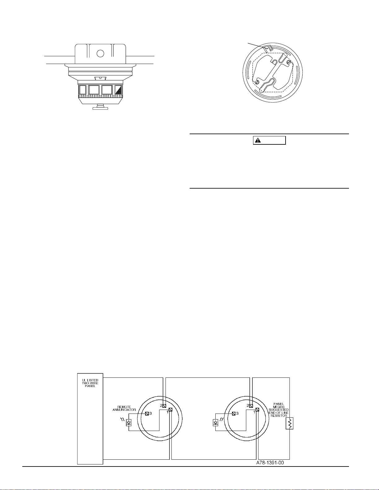
Figure 3. Wiring diagram for 2400AT detector with two-wire control panel:
D400-03-00 2 I56-287-02
Page 3

Figure 4. Wiring diagram for 2400AIT detector with isolated thermal and two-wire panels:
Detectors must be tested after installation and periodic
maintenance. System Sensor 2400AT and 2400AIT Smoke
Detectors can be tested in the following five ways:
NOTE: Before testing the detector, check for the presence
of the flashing LED. If it does not flash, power has
been lost (check the wiring), or it is defective (return for repair – refer to the Warranty).
A. Recessed Test Switch
1. Push and hold the recessed test switch with a 0.1 inch
maximum diameter tool, such as a pocket screwdriver.
2. The LED on the detector should light within 5 seconds. The p-horn should also sound.
B. Calibrated Test Card (R59-18-00)
1. Remove the detector cover by placing a small bladed
screwdriver in the side slot of the detector cover,
twisting it slightly until the cover can be turned counterclockwise for removal.
2. Insert the NO ALARM end of the test card fully into
the test slot (see Figure 6) and slide it counterclockwise until it stops.
3. The detector should not alarm (wait at least 20
seconds).
4. Remove the test card by sliding it clockwise before removing, then repeat with the ALARM end of the test
card.
5. The LED should latch on within 20 seconds, indicat-
ing alarm and annunciating the panel.
6. Replace the cover by gently rotating it clockwise until
it locks in place.
C. Test Module (System Sensor Model No. MOD400R)
The MOD400R is used with an analog or digital voltmeter to check the detector sensitivity as described in the
test module’s manual.
D. Aerosol Generator (Gemini 501)
Set the generator to represent 4%/Ft. to 5%/Ft. obscuration as described in the aerosol generator manual. Using
the bowl shaped applicator, apply aerosol until the unit
alarms.
E. Direct Heat Method (Hair dryer of 1000-1500 watts)
Direct the heat toward the bimetallic collector. Hold the
heat source about 12 inches from the detector in order to
avoid damage to the plastic. When the heat rises to
greater than 135°F the detector will latch in alarm.
The detector will reset only after it has had sufficient time
to cool and the power source has been temporarily interrupted. Both smoke and heat detection testing are recommended for verifying system protection capability.
Detectors that fail these tests should be cleaned as described under MAINTENANCE and retested. If the detectors still fail these tests, they should be returned for repair.
Notify the proper authorities the system is back on line.
Figure 5. Bottom and side views, showing position
of test switch:
Maintenance
NOTE: Before cleaning, notify the proper authorities that
the smoke detector system is undergoing mainte-
LED
RECESSED TEST
SWITCH
nance and, therefore, will be temporarily out of
service. Disable the system undergoing maintenance to prevent unwanted alarms.
1. Remove the detector cover by placing a small-bladed
screwdriver in the side slot of the detector cover, twisting it until the cover can be turned counterclockwise for
removal.
TEST MODULE
SOCKET
PUSH RECESSED SWITCH WITH
A .1" MAX. DIAMETER TOOL
2. Vacuum the screen carefully without removing it. If further cleaning is required, continue with step 3, other-
A78-1393-00
D400-03-00 3 I56-287-02
Page 4

wise skip to step 6.
3. Remove the screen by pulling it straight out. Vacuum the
inside.
4. Clean the vaned chamber piece by vacuuming out dust
and particles.
5. To replace the screen, orient it so that the arrow on top
aligns with the field test socket on the base of the detector. Carefully push the screen onto the base making sure
it fits tightly to the chamber.
6. Replace the cover by gently rotating it clockwise until it
locks in place.
The Limitations of Property Protection Smoke Detectors and Sounders
The sounder in this detector will not operate if the power is cut off for any
reason.
The sounder may not be heard. The loudness of the sounder meets or
exceeds the current standards. However, the sounder may not alert a
sound sleeper or one who has recently used drugs or has been drinking
alcoholic beverages. This sounder may not be heard if it is placed in an
area which is separated by a closed door, or if it is located on a different
floor from the person in a hazardous situation, or if it is placed too far
away to be heard over the ambient noise such as traffic, air conditioners,
machinery, or musical appliances that may prevent alert persons from
hearing the alarm.
The sounder may not be heard by persons who are hearing impaired.
In this case, a visual indicator shall also be used.
This smoke detector used with this base is designed to activate and ini-
tiate emergency action, but will do so only when used in conjunction with
an authorized fire alarm system. This detector must be installed in accordance with NFPA standard 72.
Smoke detectors will not work without power. AC or DC powered
smoke detectors will not work if the power supply is cut off .
Smoke detectors will not sense fires which start where smoke does not
reach the detectors. Smoldering fires typically do not generate a lot of
heat which is needed to drive smoke up to the ceiling where the smoke
detector is usually located. For this reason, there may be large delays in
detecting a smoldering fire with either an ionization-type detector or a
photoelectronic-type detector. Either one of them may alarm only after
flaming has initiated, which will generate the heat needed to drive the
smoke to the ceiling.
Smoke from fires in chimneys, in walls, on roofs, or on the other side of a
closed door may not reach the smoke detector and alarm it. A detector
Figure 6:
REMOVABLE COVER
TEST SLOT
CLEANABLE SCREEN
(P/N RS24T)
REMOVAL
SLOT
WARNING
cannot quickly detect, or sense at all, a fire developing on another level of
a building. For this reason, detectors shall be located on every level and
in every bedroom within a building.
Smoke detectors have sensing limitations, too. Ionization detectors and
photoelectronic detectors are required to pass fire tests of the flaming and
smoldering types. This is to ensure that both can detect a wide range of
fires. Ionization detectors offer a broad range of fire-sensing capability, but
they are somewhat better at detecting fast-flaming fires than slow-smoldering fires. Photoelectronic detectors sense smoldering fires better than
flaming fires, which have little, if any, visible smoke. Because fires develop
in different ways, and are often unpredictable in their growth, neither type
of detector is always best, and a given detector may not always provide
early warning of a specific type of fire.
In general, detectors cannot be expected to provide warnings for fires resulting from inadequate fire protection practices, violent explosions, escaping gases that ignite, improper storage of flammable liquids like
cleaning solvents that ignite, other similar safety hazards, arson, smoking
in bed, children playing with matches or lighters, etc. Smoke detectors
used in high air velocity conditions may have a delay in alarm due to dilution of smoke densities created by frequent and rapid air exchanges. Additionally, high air velocity environments may create increased dust
contamination, demanding more frequent detector maintenance.
Smoke detectors cannot last forever. Smoke detectors contain electronic
parts. Even though detectors are made to last over 10 years, any part can
fail at any time. Therefore, smoke detectors shall be replaced after being in
service for 10 years. The smoke detector system that this detector is used
in must be tested regularly per NFPA 72. This smoke detector should be
cleaned regularly per NFPA 72 or at least once a year.
A78-1409-00
Three-Year Limited Warranty
System Sensor warrants its enclosed smoke detector to be free from defects in materials and workmanship under normal use and service for a
period of three years from date of manufacture. System Sensor makes no
other express warranty for this smoke detector. No agent, representative,
dealer, or employee of the Company has the authority to increase or alter
the obligations or limitations of this Warranty. The Company’s obligation
of this Warranty shall be limited to the repair or replacement of any part of
the smoke detector which is found to be defective in materials or workmanship under normal use and service during the three year period commencing with the date of manufacture. After phoning System Sensor’s toll
free number 800-SENSOR2 (736-7672) for a Return Authorization number,
send defective units postage prepaid to: System Sensor, Repair Depart-
D400-03-00 4 I56-287-02
ment, RA #__________, 3825 Ohio Avenue, St. Charles, IL 60174. Please
include a note describing the malfunction and suspected cause of failure.
The Company shall not be obligated to repair or replace units which are
found to be defective because of damage, unreasonable use, modifications, or alterations occurring after the date of manufacture. In no case
shall the Company be liable for any consequential or incidental damages
for breach of this or any other Warranty, expressed or implied whatsoever,
even if the loss or damage is caused by the Company’s negligence or fault.
Some states do not allow the exclusion or limitation of incidental or consequential damages, so the above limitation or exclusion may not apply to
you. This Warranty gives you specific legal rights, and you may also have
other rights which vary from state to state.
© System Sensor 1996
 Loading...