

Page 1

SYNTEC
Mill Controller Manual
By: SYNTEC
(For EZ Series)
Date: 2010/9/14
Version: 1.0
Page 2

No.
Modify Content
date
editor
New Vision
01
Mill Operation Manual-EN FOR EZ(5Keys)
2010/09/14
XuMing
V1.0
Version edit record
Page 3

Contents
1 CNC MILLING CONTROLLER INTERFACE ........................................... 1
1.1 CNC System Configuration .......................................................................................................... 1
1.2 Screen Sections .............................................................................................................................. 2
1.3 Main Menu Selections ................................................................................................................... 3
1.3.1 F1:Position .......................................................................................................................... 4
1.3.1.1 F1:Coor. Switch ........................................................................................................ 5
1.3.1.2 F2:1/2 Coor. .............................................................................................................. 5
1.3.1.3 F3:Clear Coor. ........................................................................................................... 5
1.3.1.4 F4:Clear All Relative ................................................................................................ 6
1.3.1.5 F5:Workpiece Coor. .................................................................................................. 6
1.3.1.5.1 F1:Coor. Latched .................................................................................................. 7
1.3.1.5.2 F2:Rel. Latched .................................................................................................... 7
1.3.1.5.3 F3:Aux. Latched ................................................................................................... 7
1.3.1.5.4 F5:Middle Point Func. .......................................................................................... 7
1.3.2 F2:Program ......................................................................................................................... 8
1.3.2.1 F1:Insert Cycle .......................................................................................................... 9
1.3.2.2 F2:Delete Line........................................................................................................... 9
1.3.2.3 F3:Edit Cycle .......................................................................................................... 10
1.3.2.4 F4:Simulation .......................................................................................................... 11
1.3.2.4.1 F1: STEP ........................................................................................................... 11
1.3.2.4.2 F2:Continue ........................................................................................................ 11
1.3.2.4.3 F3:Zoom ............................................................................................................. 12
1.3.2.4.4 F4:Graph reset .................................................................................................... 12
1.3.2.4.5 F5:Abort ............................................................................................................. 12
1.3.2.4.6 F5:Simu. Setting ................................................................................................. 12
1.3.2.5 F5:File Manager ...................................................................................................... 13
1.3.2.5.1 F1:New File ........................................................................................................ 14
1.3.2.5.2 F2:Copy File ....................................................................................................... 14
1.3.2.5.3 F3:Delete File ..................................................................................................... 14
1.3.2.5.4 F4:Import ............................................................................................................ 15
1.3.2.5.5 F5:Export ............................................................................................................ 16
1.3.2.5.6 F1:RS232 Import ................................................................................................ 17
1.3.2.5.7 F2 :RS232 Export .................................................................................................. 19
1.3.2.5.8 F3:Network Import ................................................................................................ 20
Page 4

1.3.2.5.9 F4:Multi Import ..................................................................................................... 20
1.3.2.5.10 F5:Multi Export .................................................................................................... 20
1.3.2.6 EDIT .......................................................................................................................... 20
1.3.2.6.1 EDIT sub function “F1 : Search” .......................................................................... 21
1.3.2.6.2 EDIT sub function “F2 : Replace” ........................................................................ 22
1.3.2.6.3 EDIT sub function “F3” : Go To Line” ................................................................. 23
1.3.2.6.4 EDIT sub function “F4”: copy line”...................................................................... 23
1.3.2.6.5 EDIT sub function “F5”: Insert line” .................................................................... 23
1.3.2.7 F2:Teach ................................................................................................................. 24
1.3.2.7.1 F1:Rapid Teach .................................................................................................. 24
1.3.2.7.2 F2:Line Teach .................................................................................................... 24
1.3.2.7.3 F3:Arc Teach ...................................................................................................... 24
1.3.2.7.4 F4:Cancel Middle ................................................................ ............................... 25
1.3.2.7.5 F5:Radius Teach ................................................................................................. 25
1.3.2.7.6 F1:Delete Line .................................................................................................... 25
1.3.2.7.7 F2:Coord Switch ................................................................................................ 25
1.3.2.7.8 F3:Point Teach ................................................................................................... 25
1.3.3 F3:DlgInput (ONLY for 940M) ........................................................................................ 26
1.3.4 F4:Monitor ........................................................................................................................ 26
1.3.4.1 F1:Coor ................................................................................................................... 26
1.3.4.2 F2:Graph Adjust ...................................................................................................... 27
1.3.4.2.1 F1:Zoom ............................................................................................................. 27
1.3.4.2.2 F2:Graph Reset ................................................................................................... 27
1.3.4.2.3 F5:Simu Setting .................................................................................................. 27
1.3.4.3 F3:MDI Input .......................................................................................................... 28
1.3.4.4 F4:SETTING ........................................................................................................... 29
1.3.4.5 F5:Tool Setting ....................................................................................................... 30
1.3.4.6 F5:Work Record ...................................................................................................... 31
1.3.5 F5:Alarm........................................................................................................................... 32
1.3.5.1 F1:Actual................................................................................................................. 33
1.3.5.2 F2:History ............................................................................................................... 33
1.3.5.3 F5: Save ..................................................................................................................... 33
1.3.6 F1:Parameter ..................................................................................................................... 34
1.3.7 F2:Diagnosis ..................................................................................................................... 35
1.3.7.1 F1:PLC State ................................................................................................ ........... 36
1.3.7.2 F2:System Data ....................................................................................................... 37
1.3.7.3 F3:Global Variable .................................................................................................. 38
1.3.7.4 F4:Coord Variable ................................................................................................... 39
Page 5

1.3.7.5 F5:System Manager ................................................................................................ 40
1.3.8 F3:Guidance ..................................................................................................................... 41
2 MACHINE OPERATION PANEL ............................................................ 42
2.1 2nd machine operation panel ....................................................................................................... 42
2.1.1 POWER ON ........................................................................................................................ 42
2.1.2 POWER OFF ....................................................................................................................... 42
2.1.3 Emergency STOP ................................................................................................................ 42
2.1.4 Home mode and Home function .......................................................................................... 42
2.1.5 Continues JOG (Rapid JOG) ............................................................................................... 42
2.1.6 Incremental JOG .................................................................................................................. 43
2.1.7 MPG JOG ............................................................................................................................ 43
2.1.8 AUTO mode NC file execute .............................................................................................. 43
2.1.9 MDI mode single block execute .......................................................................................... 43
2.1.10 MPG Simulation .................................................................................................................. 44
2.1.11 Dry Run ............................................................................................................................... 44
2.1.12 Single block ......................................................................................................................... 44
2.1.13 Option Stop.......................................................................................................................... 45
2.1.14 Option Skip.......................................................................................................................... 45
2.1.15 Spindle control .................................................................................................................... 45
2.1.16 Working led ......................................................................................................................... 46
2.1.17 Working Liquid ................................................................................................................... 46
2.1.18 Aux table backward ............................................................................................................. 46
2.1.19 Aux table forward ................................................................................................................ 46
2.2 Text key description: .................................................................................................................. 47
3 HOW TO OPERATE SYNTEC 900ME ................................................... 49
3.1 Manual function (JOG, INC_JOG, MPG) ................................................................................ 50
3.2 HOME .......................................................................................................................................... 51
3.3 Open a file (EDIT / FLOPPY / RS232) ..................................................................................... 52
3.4 Tool setting (G40/G41/G42, G43/G44/G49) ................................................................ .............. 53
3.5 Tool Length measurement (G43/G44/G49) ................................................................ ............... 54
3.6 Setting the Workpiece origin offset value (G54...G59)............................................................. 55
Page 6

3.7 Manual Data Input (MDI) .......................................................................................................... 56
3.8 Assigned an executing NC file (AUTO) ..................................................................................... 57
3.9 Graphic Simulation ..................................................................................................................... 58
3.10 How to check NC file in SYNTEC controller....................................................................... 59
3.11 Auto Center............................................................................................................................. 60
3.11.1 Manual Center ..................................................................................................................... 60
3.11.2 Auto center operation .......................................................................................................... 62
3.12 Z-axis Auto Tool ..................................................................................................................... 64
3.13 RS232 FUNCTION ................................................................................................................ 69
3.14 DNC Function ......................................................................................................................... 71
3.15 The software of SYNTEC controller replace the software of DNC to execute RS232
function 73
Page 7

Coor
1/2 Coor
Clear Coor
All Clear Relative
Workpiece Coor
Position
F1
Insert Cycle
Delete Line
Edit Cycle
Search
Replace
Go To Line
Copy Line
Insert Line
Edit
Rapid Teach
Line Teach
Arc Teach
Cancel Middle
Delete Line
Teach
Step
Continue
Zoom
Graph Reset
Abort
Simu. Setting
Simu.
New File
Copy File
Delete File
Import
Export
RS232 I mport
RS232 Export
File Manager
Program
F2
Dlginput
F3
Coor
Graph Adjust
MDI Input
Setting
Tool setting
Work Record
Monitor
F4
Actual
History
Save
Alarm
F5
System Param
Go to page One
Operation Setting
Param.
F6
PLC I Bit
PLC O Bit
PLC C Bit
PLC S Bit
PLC A Bit
PLC Register
PLC Timer
PLC Counter
PLC State
System Data
Global Data
Software Setup
Backup System
Install Local L.
Store Language
System Manger
Diagnosis
F7
Guidance
F8
CNC Mill
1 CNC Milling Controller Interface
1.1 CNC System Configuration
-1-
Page 8

1.2 Screen Sections
The screen of controller is shown as followings:
Meanings For Fields on the Display:
(1)Program Number
(2)Title
(3)Time
(4)Date
(5)Data Input
(6)Hint
(7)Status
(8)Function Key Switch
-2-
Page 9

1.3 Main Menu Selections
The following diagram is the main menu selections for SNC Mill
controller. To operate SNC Milling controller, users simply make the
selections by pressing function keys, F1~F5 located on the bottom of the
screen.
-3-
Page 10

1.3.1 F1:Position
This selection displays coordinate settings of current position. It can
also be used to reset the position of relative coordinate. Pressing function
key, F1, under the main menu to enter this selection (Note:This is the first
screen when the system is booted up)
Meaning of fields on the display------
X:X axis coordinate.
Y:Y axis coordinate.
Z:Z axis coordinate.
Feedrate:Feedrate of cutting tool at each machining, mm per minute (mm/min).
Spindle:RPM of spindle speed.
Machine(Relative coordinate of working platform)
The current position of cutting tool relative to working platform is shown as machine
coordinate on the display.
Relative
The current position of cutting tool relate to the previous location.
Absolute(Programming Coordinate)
The current position of the origin of user defined coordinate is shown as an absolute
position on the display.
Distance To Go:The distance of the cutting tool that need to move to the next position
show on position(+) and negative(-) direction.
-4-
Page 11

Function key selections:
1.3.1.1 F1:Coor. Switch
Function:Switch Coordinate Display。
Operation:Under the Position submenu, whenever users press F1 key, the values and
coordinate on the left corner of the display will toggle among the four different
coordinates with bigger fonts as shown in the following figure:
1.3.1.2 F2:1/2 Coor.
Function: Set the center point of work piece as coordinate origin.
Operation: Under the Position submenu, when the message line shows “X Input”(or
“Y Input” or “Z Input”), press “F2 1/2 Coordinating” and the origin of the coordinate
will move to the center point of work piece.
1.3.1.3 F3:Clear Coor.
Function:Reset the value of X(or Y or Z) axis relative coordinate to zero. (No effect
on other axes)
Operation:Under the Position submenu, when the message line shows “X Input”(or
“Y Input” or “Z Input”), press F3 to reset the value of X(or Y or Z) axis relative
coordinate to zero.
-5-
Page 12

1.3.1.4 F4:Clear All Relative
Function:Reset XYZ relative coordinate to zero.(No effect on other coordinates)
Operation :Under the Position submenu, pressing “F4” will reset XYZ relative
coordinate to zero.
1.3.1.5 F5:Workpiece Coor.
Function:Relative to machine coordinate setting for G54~G59.
Operation:Under the Position submenu, press "F5" key and the following screen will
show up. The users can begin to set the auto machine coordinate settings of G54~G59.
(The system needs to be in Ready Status)
1. “External Shift” : operator can set the all coordinate
G54..G59 at the same time .
2. CNC default G54 ,if user don‟t set any G54..G59 in the NC
file
-6-
Page 13

1.3.1.5.1 F1:Coor. Latched
Set the current machine coordinate to the input box
1.3.1.5.2 F2:Rel. Latched
Set the current relative coordinate to the input box
1.3.1.5.3 F3:Aux. Latched
Set the current relative coordinate to the input box
1.3.1.5.4 F5:Middle Point Func.
-7-
Page 14

1.3.2 F2:Program
This selection provides users with program file management and
editing. With a full screen editor, users can use arrow keys(↑、↓、←、→)
to move the cursor to anywhere on the screen for editing purpose. Press F2
under the main menu to enter this selection. The full screen editor is shown
as follows:
-8-
Page 15

Program Sub menu Key Selections:
1.3.2.1 F1:Insert Cycle
Function:Insert a block or cycle by conversation
Operation:Under Program submenu, press F1 to insert a line or cycle before cursor
position.(See Graphic Input Interface(900ME) User Guide)
1.3.2.2 F2:Delete Line
Function:Delete a line at cursor position.
operation: Under Program submenu, press F2 to delete a line where the cursor is
located.
-9-
Page 16

1.3.2.3 F3:Edit Cycle
Function:Edit an old block or cycle by conversation input
Operation: Under Program submenu, press F3 to edit a line where the cursor is
located.
-10-
Page 17

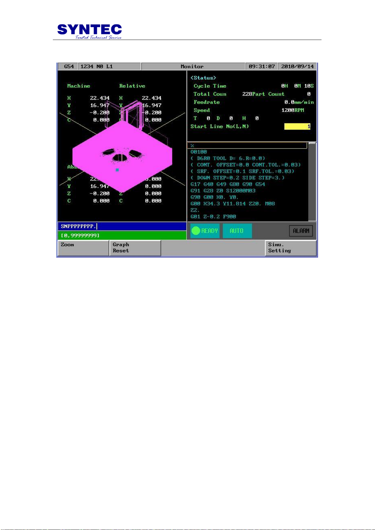
1.3.2.4 F4:Simulation
Function: Simulating the workpiece program can prove the accuracy of the editing
program.
Operation:Under Program submenu, press F4
F4 “simulation” sub Key Selections:
1.3.2.4.1 F1: STEP
Function: To simulate NC files STEP by STEP
Operation: Under Program submenu, press F4”Simulation” and then F1”Step” .The
operator can use this function ,to check NC file STEP by STEP
1.3.2.4.2 F2:Continue
Function: To simulation NC file one time .
Operation: Under Program submenu, press F4 “Simulation” and then
F2”Continue” .The operator can use this function to check NC file whole
picture ,when push button.
-11-
Page 18

1.3.2.4.3 F3:Zoom
Function: To enlarge the workpiece graph.
Operation: Under Program submenu, press F5 and then F3.The operator can use the
“←”,”↑”,”→”, ”↓” cursor to move the frame to the determined area. And use
“PageUp” “PageDn” to Enlarge this area .
1.3.2.4.4 F4:Graph reset
Function: To recover the zoomed workpiece graph.
1.3.2.4.5 F5:Abort
Function: To abort simulation action
1.3.2.4.6 F5:Simu. Setting
Function: To set simulation parameter
Operation: Under Program submenu, press and then F5.
Simulation Parameter description :
Path color : User can select cutting path color by this parameter
Cursor color : User can select cutting point color by this parameter
Drawing mode : User can select simulation plane by this parameter
Vertical / Horizontal angle : when XYZ drawing mode ,user can select 3D View angle
by these 2 parameter
Window range :
Mode (0: simulation ,1: direct draw)
-12-
Page 19
0 : When operator change his main screen to F4”Monitor” ,CNC would
automatically simulation at that screen
1 : When operator change his main screen to F4”Monitor” ,CNC would not
simulation at that screen but direct drawing the cutting cursor .
Xmin/Xmax, Ymin/Ymax ,Zmin/Zmax :
When “direct draw” mode ,operator must set draw window by these
parameter ,the best way : after simulation use simulation result which is
located at the top of this screen to X,Y,Z range .
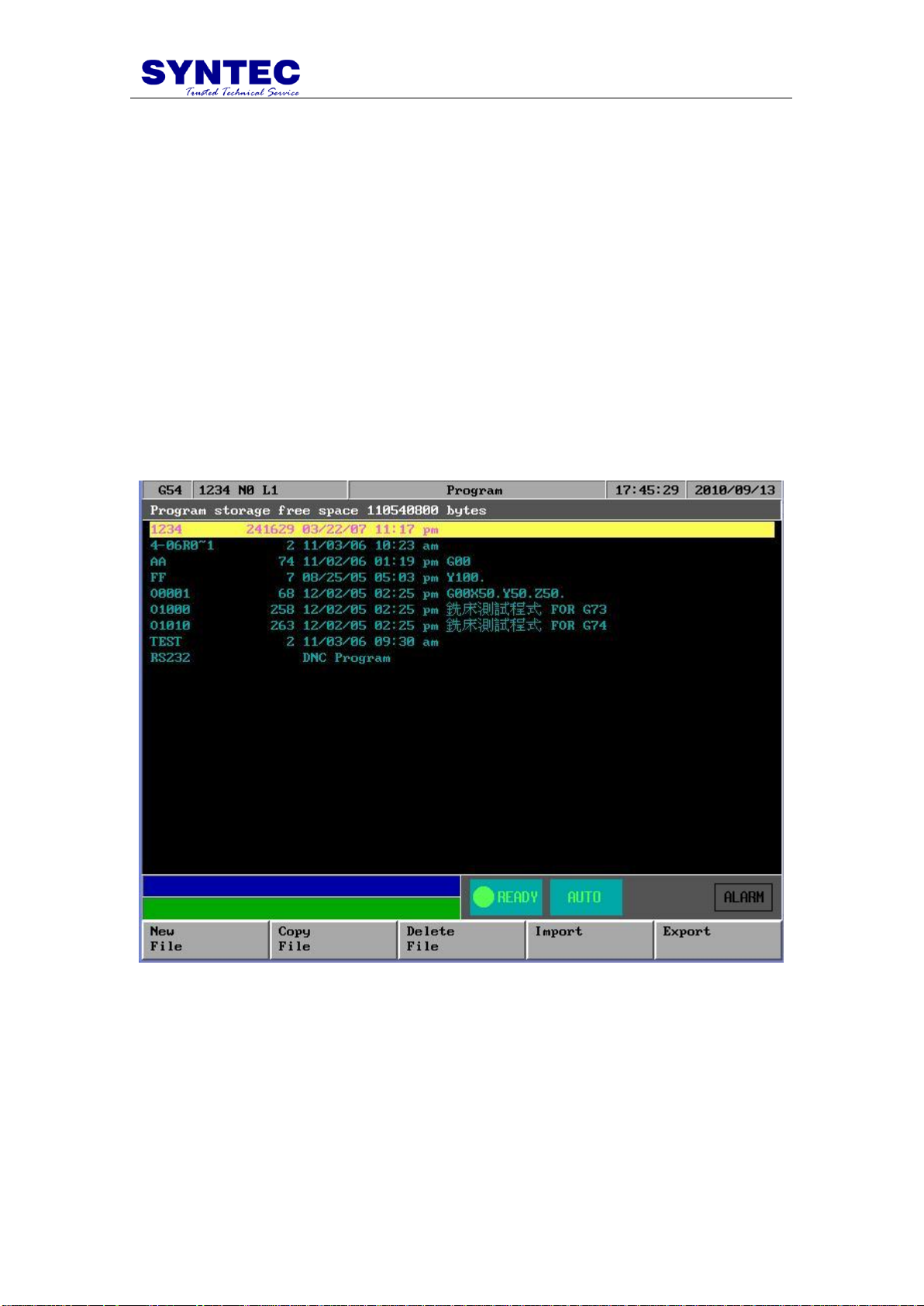
1.3.2.5 F5:File Manager
Under Program submenu, press F5 and the following diagram will
show up. Users can use arrow keys(↑、↓)to select file to be edited. After
pressing【ENTER】, content of the file will show up on the screen
-13-
Page 20

Key Selections:
1.3.2.5.1 F1:New File
Operation:
Step 1: A dialog box will prompt users with “New File ”. Type in
the new file name and press 【ENTER】.
Step 2: An empty screen shows up waiting users to type in a new
program.
1.3.2.5.2 F2:Copy File
Operation: After pressing F2, a dialog box will prompt users to type in a file name and
press 【ENTER】. The current file is then copy to the hard disk with a different file
name.
1.3.2.5.3 F3:Delete File
Operation: Select a file to be delete by pressing (↑、↓). A dialog box will pop up
to confirm this operation.
-14-
Page 21

1.3.2.5.4 F4:Import
Function:Input file from floppy.
Operation:Insert a disk to the floppy drive and then press F4. Select a file name by
pressing(↑、↓、←、→). Press【ENTER】to input the file from a floppy disk
.
P.S.
1. floppy disk file format is ASCI code
2. SYNTEC CNC also can accept *.zip format ,when import
from floppy disk ,cnc would unzip automatically
3. if NC file too big ,operator can use more than ONE floppy
disk to import nc FILE , separates a big file to some floppy
disks ,use the same file nmae ,then inport THIS file DISK
BY DISK ,operator choose appEnd but not overWRITE ,IT
IS VERY EASY TO INSATLL A BIG FILE
4. IF OPERATOR INSTALL EHTERNET ,IT IS MORE
EASY TO INSTALL A BIG FILE FROM NET .
-15-
Page 22
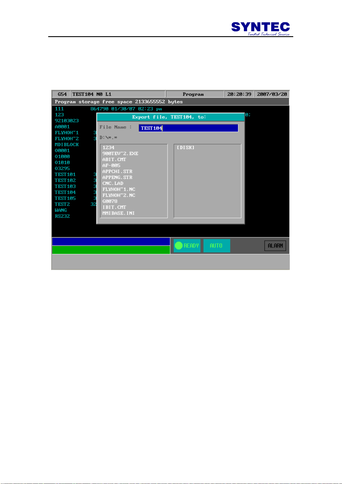
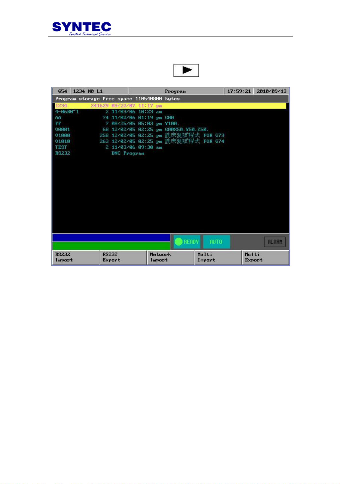
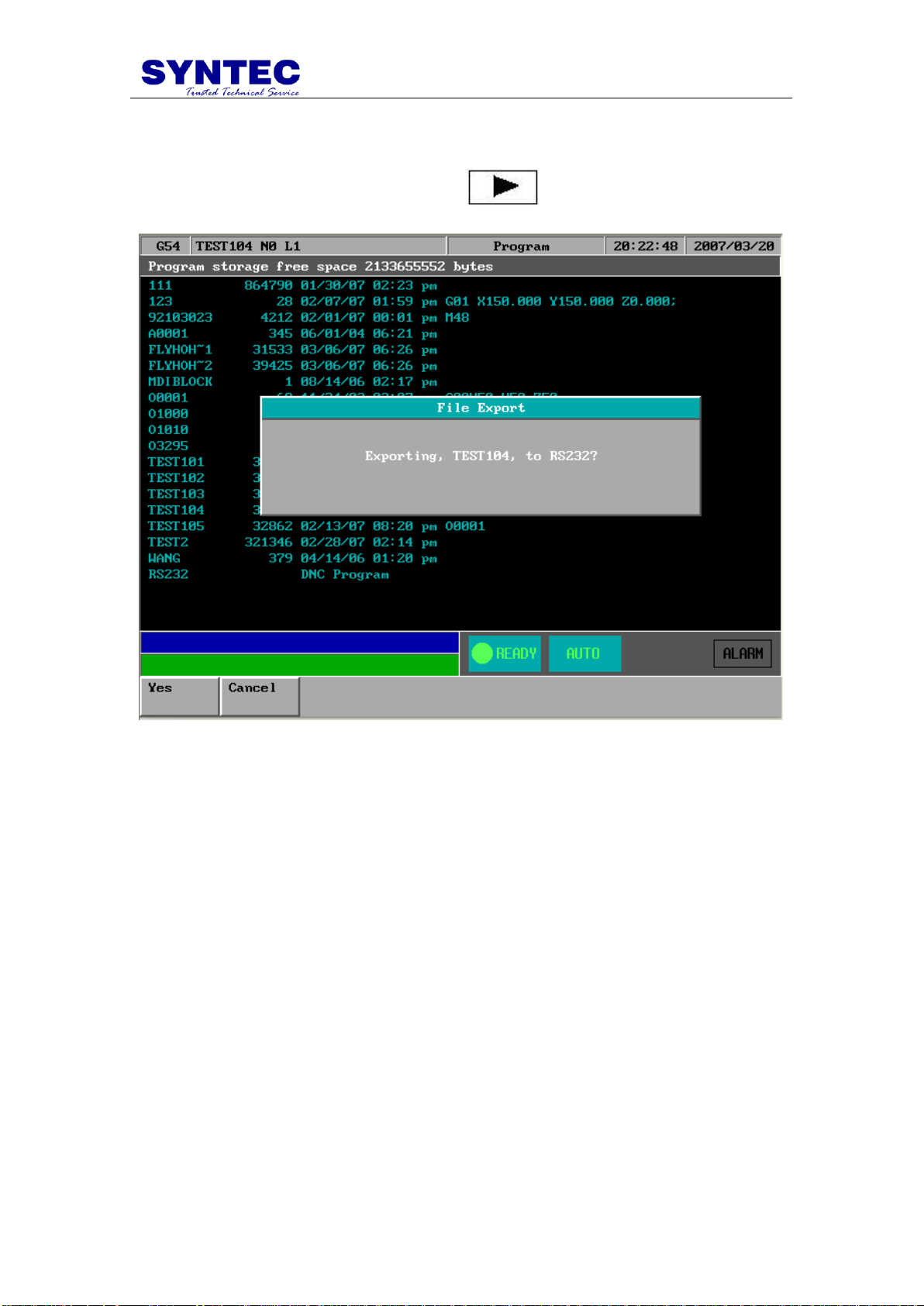
1.3.2.5.5 F5:Export
Function: Output file to floppy disk
Operation: Select a file by pressing(↑、↓、←、→)and then press F5. After following
the prompt in the dialog box, confirm this operation by pressing 【ENTER】.
-16-
Page 23
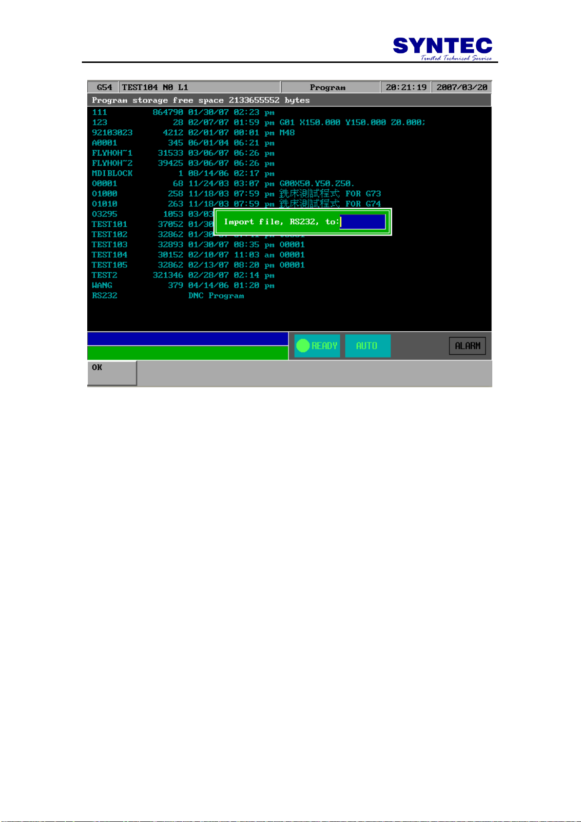
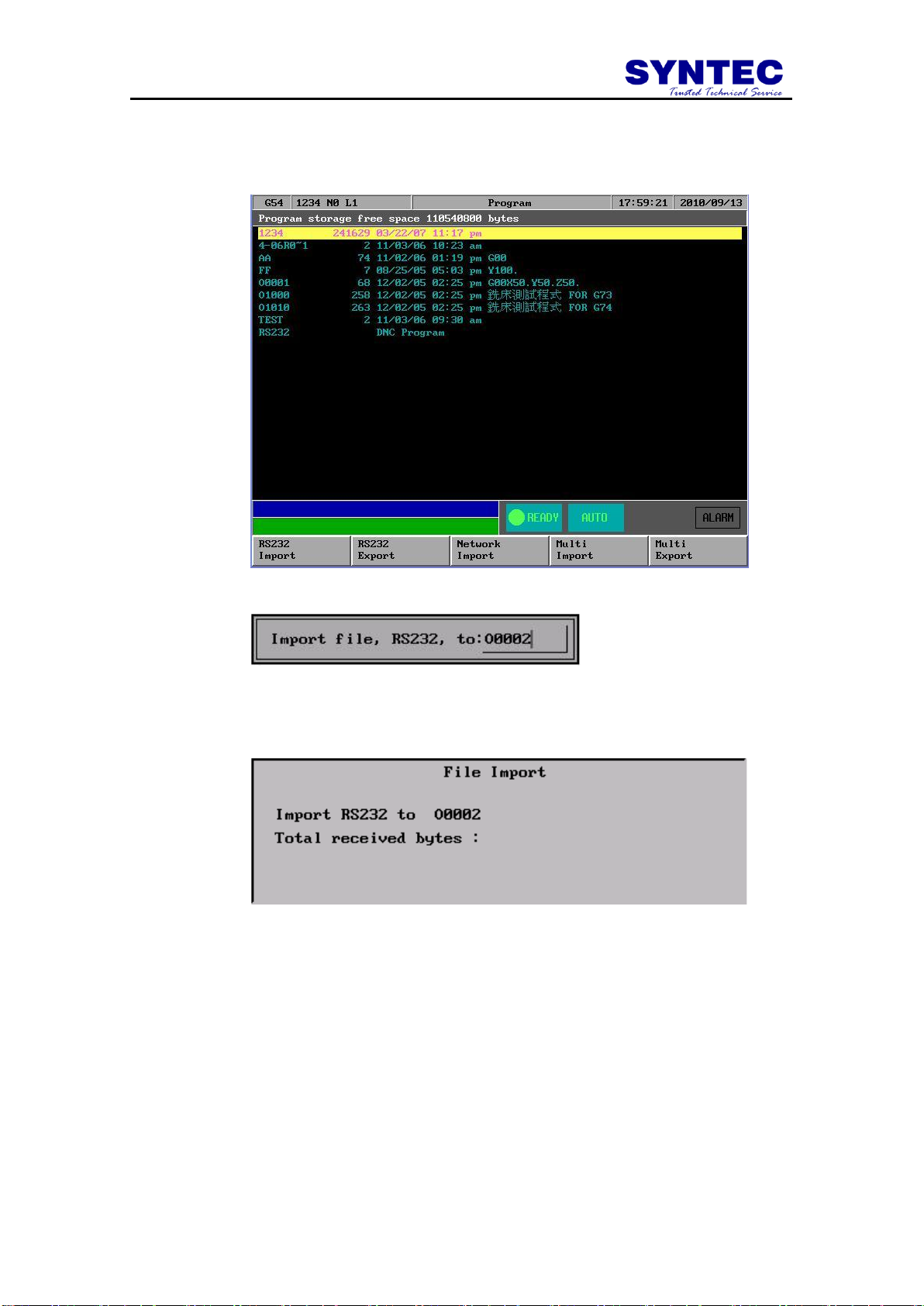
1.3.2.5.6 F1:RS232 Import
Function: use RS232 communication function to import NC files
Operation: Under Program submenu, press and then F1.Follow the
prompts in the dialog box and type in needed data.
-17-
Page 24
-18-
Page 25
1.3.2.5.7 F2 :RS232 Export
Function: Use RS232 communication function to Export NC files
Operation: Under Program submenu, press and then F2.
-19-
Page 26

1.3.2.5.8 F3:Network Import
Function: Use Net communication function to Import NC files
Operation: Under Program submenu, press and then F3.
1.3.2.5.9 F4:Multi Import
Function: Import multi NC files once time
Operation: Under Program submenu, press and then F4.
1.3.2.5.10 F5:Multi Export
Function: Export multi NC files once time
Operation: Under Program submenu, press and then F5.
1.3.2.6 EDIT
Function : Edit sub function “ Search “ “Replace” “Goto line” “Copy line” ”Insert
line”
Operation : Under Program submenu, press and then F1. User can use this
menu for more edit sub function
-20-
Page 27

1.3.2.6.1 EDIT sub function “F1 : Search”
Function:Search String。
Operation:Under Program submenu, press F5”EDIT” and then F1 “Search” to
search string. An dialog box will pop up asking users to input a string as shown in
the following figure. After keying in a string, press F1 to start searching.
-21-
Page 28

1.3.2.6.2 EDIT sub function “F2 : Replace”
Function:Replace String.
Operation:Under Program submenu, press F5 “EDIT” and then F2”Replace” to
replace string. An dialog box will pop up asking users to input the replacing string
and the new string as shown in the following figure. After keying in a string, press
F1 to start replacing.
-22-
Page 29

1.3.2.6.3 EDIT sub function “F3” : Go To Line”
Function:Go to a line number
Operation:Under Program submenu, press F4”EDIT” and then F3”GOTO line” to go
to the line number. A dialog box will pop up asking users to input a line number.
After keying in a number, press F1 to go to the desired line.
1.3.2.6.4 EDIT sub function “F4”: copy line”
Function:Copy a line from current cursor to next line
Operation:Under Program submenu, press F5 “EDIT” and then F4”Copy line” to go
to the next line.
1.3.2.6.5 EDIT sub function “F5”: Insert line”
Function:Insert a space line above current cursor line
Operation:Under Program submenu, press F5 “EDIT” and then F5”Insert line” to
Insert a new space line
-23-
Page 30

1.3.2.7 F2:Teach
Function: Teach present absolute coordinate to NC files
Operation:Under Program submenu, press and then F2.
Teach sub Key Selections:
1.3.2.7.1 F1:Rapid Teach
Function: Add “G00” code to NC files, G00 to current absolute coordinate,
1.3.2.7.2 F2:Line Teach
Function: Add “G01” code to NC files, G01 to current absolute coordinate,
1.3.2.7.3 F3:Arc Teach
Function: Add “G02” or “G03” code to NC files
1. 1st time press this key “arc teach “ ,CNC auto put current
value to Arc middle point
2. 2nd time press this key “arc teach “ ,CNC auto calculate
G02 or G03 ,and filled the complete code to NC files
-24-
Page 31

1.3.2.7.4 F4:Cancel Middle
Function: When arc teach ,user can use this key to abort middle point teach .
1.3.2.7.5 F5:Radius Teach
Function: Add “G02” or “G03” code to NC files by G_code menu and Arc Radius
1.3.2.7.6 F1:Delete Line
Function: When user use Teach function , user can use this key “Delete line “ to
delete line
Operation:Under Teach press and then F1.
1.3.2.7.7 F2:Coord Switch
Function: When the number of axis is more than 4-axis ,user can use this key to
switch absolute coordinate of other axis.
Operation:Under Teach press and then F2.
1.3.2.7.8 F3:Point Teach
Function: Add current absolute coordinate to NC files.
Operation:Under Teach press and then F2.
-25-
Page 32

1.3.3 F3:DlgInput (ONLY for 940M)
Pressing "F3" under the main menu to begin dialog box input as shown
in the following figure. After users follow the prompts shown on the dialog
box to key in every needed parameter, the CNC milling controller can start
milling a work piece immediately.
1.3.4 F4:Monitor
This selection displays machining speed, time, manual data input (MDI)
and some machine information such as coordinate, range or program at the
run time. Press F4 under the main menu to select this function.
Key Selections:
1.3.4.1 F1:Coor
Function: Toggle way of display among the four different coordinate systems,
graphical working paths display and the absolute coordinate. (Absolute coordinate
display at the upper right corner of the left half screen.)
Operation: Under Monitor submenu, press F1 to toggle coordinate display between
the four coordinates as shown as the following figure:
-26-
Page 33
1.3.4.2 F2:Graph Adjust
Key Selections:
1.3.4.2.1 F1:Zoom
Function: To enlarge the workpiece graph.
Operation: Under Monitor submenu, press F2 and then F1.The operator can use the
cursor to move the frame to the determined area.
1.3.4.2.2 F2:Graph Reset
Function: To recover the zoomed workpiece graph.
Operation: Under Monitor submenu, press F2”Graph Adjust” and then F2”Graph
Reset”
1.3.4.2.3 F5:Simu Setting
Function: To set simulation parameter
Operation: Under Monitor submenu, press F2”Graph Adjust” and then F5”Simu
Setting” .
-27-
Page 34

1.3.4.3 F3:MDI Input
Function:Manual Data Input
Operation:Users can operate SNC Milling Controller manually in MDI mode. Press
F3 under Monitor submenu and type in single-line G or M code. Press F1 (OK) to
confirm the input command. The typed-in command line will show on right upper
corner of the screen. Users simply press 【CYCLE START】on the machine panel to
execute the single-line command. The following figure shows an example of this
function.
-28-
Page 35

1.3.4.4 F4:SETTING
Function:To set the part count and also set required current
Operation:From this screen users can set the part count what he needs
1. When CNC execute M02 ,M30 ,M99 ,part count would add 1
automatically ,
2. When part count reach required part count ,CNC would stop
executing.
-29-
Page 36

1.3.4.5 F5:Tool Setting
Function:To set the tool compensation value
Operation:
Radius : G41/G42 tool radius Dn compensation (not diameter)
Radius wear : for small radius dimension adjust
Length : G43/G44 tool length Hn compensation
Length wear : for small length dimension adjust
-30-
Page 37
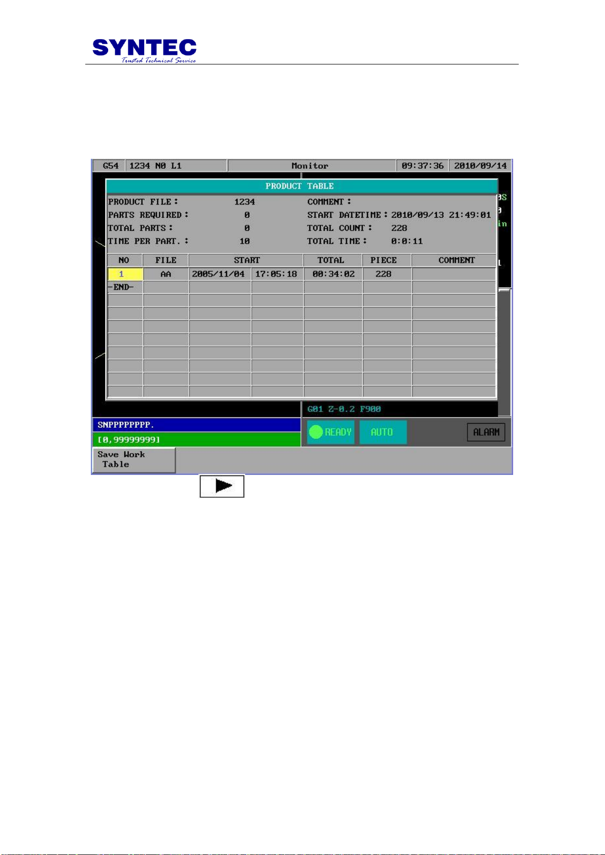
1.3.4.6 F5:Work Record
Function:This table can record 300 sets executed NC file ,this is very helpful to know
the end of user working history .
Operation: Under
Mo
nitor submenu, press and then F5.
-31-
Page 38
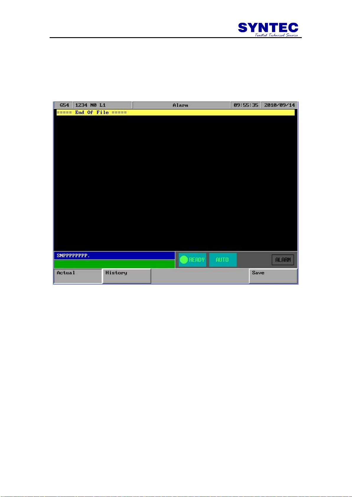
1.3.5 F5:Alarm
Whenever the system or the program stops running due to some errors,
there will be an alarm message shown on the screen. In order to clear the
errors, users can press F5 in the main menu for Alarm submenu as shown in
the following figure.
-32-
Page 39

Key Selections:
1.3.5.1 F1:Actual
Operation: Under the Alarm submenu, press F1 to show current alarm situation.
1.3.5.2 F2:History
Operation: Under the Alarm submenu, press F2 to show the alarm history of the
system.
1.3.5.3 F5: Save
Function:Save Alarm History To File.
Operation:Under the Alarm submenu, press F5 to save alarm history to a file as
shown in the following figure. A dialog box will prompt users to type in file name
to be saved. After selecting a disk drive by using (、、、), users press
【ENTER】to confirm this operation.
-33-
Page 40

1.3.6 F1:Parameter
Under the main menu, press and then F1 to enter this
function as shown in the following figure.
-34-
Page 41

1.3.7 F2:Diagnosis
This selection provides users with direct access to the memory area for
parameter checking, parameter settings and NC diagnosis function. It can
also be used to maintain and debug the control devices. Under the main
menu, press and then F2 to access this function as shown in the
following figure.
-35-
Page 42

Key Selections:
1.3.7.1 F1:PLC State
Function:for upgrade system software ,or Ladder ,system parameter …
-36-
Page 43

1.3.7.2 F2:System Data
Function:
-37-
Page 44

1.3.7.3 F3:Global Variable
-38-
Page 45

1.3.7.4 F4:Coord Variable
-39-
Page 46

1.3.7.5 F5:System Manager
-40-
Page 47

1.3.8 F3:Guidance
If users have any problem about SNC Mill controller, in addition to
user manual, users can also use this function for on-line help. Under the
main menu, press then F3 for on-line help.
-41-
Page 48

2 Machine operation panel
2.1 2nd machine operation panel
2.1.1 POWER ON
Turn on main power
2.1.2 POWER OFF
Turn off power
2.1.3 Emergency STOP
For safety reason ,press this button ,CNC would stop all
movement ,and also stop all main power . So ,people and machine safety is
guarantee .
2.1.4 Home mode and Home function
Description : When CNC power is on ,please do the home function
Operation :
1. Mode select to HOME mode
2. Press axis manual key X+,X-,Y+,Y-,Z+,Z-:
3. CNC would start the machine home function
2.1.5 Continues JOG (Rapid JOG)
Description : User can use this function to move the machine by press JOG key
Operation :
1. Mode select to CON JOG mode
2. Press axis manual key X+,X-,Y+,Y-,Z+,Z- ,work table
would move
3. Operator can use JOG% or G01% adjust Jog federate
4. When operator press manual key and rapid Key “〰” at the
same time
5. CNC would move the work table “RAPID speed”
6. Operator can use G00% Rapid Jog federate
G00 % : Adjust G00 % (F0 .25% .50% .100%)
G01 % : Adjust G01/G02 /G03 feedrate override %:
-42-
Page 49

2.1.6 Incremental JOG
Description : User can use this function to move the machine by press JOG key
Operation :
1. Mode select to INC JOG mode
2. Press axis manual key X+,X-,Y+,Y-,Z+,Z- ,work table
would move a fixed distance
3. Operator can set the incremental distance by G00 rotary
switch
4. , *1 : 1um ,*10 : 10um ,*100 : 100um
2.1.7 MPG JOG
Description : User can use this function to move the machine by MPG(Manual
Pulse Generator )
Operation :
1. Mode select to MPG mode
2. Select axis by hand box
3. Select incremental distance
4. Press axis manual key X+,X-,Y+,Y-,Z+,Z- ,work table
would move a fixed distance *1 : 1um , *10 : 10um ,
*100:100um , *1000 : 1000um
2.1.8 AUTO mode NC file execute
Description : User use this function to execute NC file
Operation :
1. mode select to AUTO mode
2. After Home function .AUTO mode is available
3. Set workpiece coor.(G54..G59) ,CNC default G54 ,if user
don‟t set any G54..G59 in the NC file
4. Set to “Tool Setting” ,to select tool radius and tool length .
5. Press “START” key to start the NC program .
6. Press “Feedhold” key to feedhold the NC program ,if it‟s
necessary
2.1.9 MDI mode single block execute
Description : User use this function to execute a block without NC file
Operation :
1. mode select to MDI mode
2. After Home function .MDI mode is available
3. Main function select F4”Monitor”
4. Press F3 “MDI Input”, screen would pop up a window.
5. After key in data ,press “ENTER” key to input the data
6. Press “START” key to start the MDI block.
7. If MDI block syntax is correct ,data in MDI menu would
disappear
-43-
Page 50

2.1.10 MPG Simulation
Description : User can use this function to check NC file
Operation :
1. Mode select to AUTO mode
2. Press this button ,and button led light “ON”
3. Press “START” key to start the NC file.
4. CNC would change machine status from “READY” to
“BUSY”
5. Machine is still not moving
6. Operator can use rotate MPG to start the NC file
7. MPG rotate faster ,machining speed is faster
8. When MPG stop ,CNC stop.
9. This function can “Enable” “ Disable” immediately
P.S. this function is very friendly for user to check his programs
2.1.11 Dry Run
Description : User can use this function to check NC file
Operation :
1. Mode select to AUTO mode
2. Press this button ,and button led light “ON”
3. Press “START” key to start the NC file.
4. CNC would change machine status from “READY” to
“BUSY”
5. This function can “Enable” “ Disable” immediately
2.1.12 Single block
Description : User can use this function to check NC file
Operation :
1. Mode select to AUTO mode
2. Press this button ,and button led light “ON”
3. Press “START” key to start the NC file.
4. CNC would execute NC file only one block and STOP
5. CNC would change machine status from “BUSY ” to
“B_STOP”
6. Press “START” again ,then CNC execute next block
7. This function is for user to check his NC file Block by Block
-44-
Page 51
2.1.13 Option Stop
Description : User can use this function to decide NC file M01 is STOP or not
Operation :
1. Mode select to AUTO mode
2. Press this button ,and button led light “ON”
3. Press “START” key to start the NC file.
4. When CNC execute “M01” ,CNC would STOP
5. CNC would change machine status from “BUSY ” to
“Feedhold”
6. This function uses to change tool or check workpiece
2.1.14 Option Skip
Description : User can use this function to decide NC file „/” is skip or not
Operation :
1. Mode select to AUTO mode
2. Press this button ,and button led light “ON”
3. Press “START” key to start the NC file.
4. When CNC execute “/” ,CNC would skip this block
5. If this key is not pressed ,CNC would execute this block
2.1.15 Spindle control
Spindle CW rotate
Spindle stop
Spindle CCW rotate
Spindle low speed: When spindle is rotate, press this key,
spindle would rotate with low speed
-45-
Page 52

2.1.16 Working led
ON/OFF working led
2.1.17 Working Liquid
Flush working liquid
2.1.18 Aux table backward
2.1.19 Aux table forward
-46-
Page 53
~
:
English 26 character key
~
:
numerical key
:
delete a character
:
Insert /replace mode switch
:
for select keyboard the other textkey
:
for select keyboard the other textkey
:
”Backspace” delete a character
:
”RESET “ abort the CNC status ,so please be careful to
use this key
:
to input current data to input box
:
press this key ,user can get help message about this
screen
:
for optional skip key input
:
end of block
:
decimal fraction
“(“, “)”, “[“, “]”, “|”, “!”, “&”, “$”, “#”, “<”, “>”, “=”, “%”, “@”, “*”, “:”, “,”, “+”, “-“
Above symbols are used for “Program Edit” mode.
2.2 Text key description:
-47-
Page 54

:
edit cursor Page Up /Page Down
:
edit cursor control key
-48-
Page 55

3 How to operate SYNTEC 900ME
This chapter is written for user task,when user operates this
controller ,operator can follow task description as below STEP by STEP ,so
very easy to use this controller ,TASK description as below :
1. Manuel function(JOG ,INC_JOG ,MPG)
2. HOME
3. Open a file (EDIT / FLOPPY /RS232 )
4. Tool setting (G40/G41/G42 ,G43/G44/G49)
5. Tool Length measurement (G43/G44/G49)
6. Setting the Workpiece origin offset value(G54..G59)
7. Manual Data Input(MDI )
8. Assigned an executing NC file (AUTO)
9. Graphic Simulation
10. How to check NC file in SYNTEC controller
11. Auto center
12. Auto Tool
-49-
Page 56

3.1 Manual function (JOG, INC_JOG, MPG)
When power on SYNTEC CNC, there are 3 mode to manual machine
1st CON_JOG :
1. Release emergency stop button ,CNC status “NOT READY”
change to “READY ”
2. Mode select switch rotate to JOG mode
3. Press axis direction key(X+,X-,Y+,Y-,Z+…) ,table would
move
4. Operator can use JOG% adjust JOG speed
5. Operator can press axis direction key and rapid key “~” at
the same time, machine will move by rapid speed
6. Rapid JOG speed can be adjusted by G00%
Incremental JOG :
1. Release emergency stop button ,CNC status “NOT READY”
change to “READY ”
2. Mode select switch rotate to INC JOG mode
3. Press axis direction key(X+,X-,Y+,Y-,Z+…) ,table will
move a fixed distance once
4. Operator can select incremental distance by G0%
(*1,*10,*100)
MPG incremental jog (MPG):
1. Release emergency stop button ,CNC status “NOT READY”
change to “READY ”
2. Mode select switch rotate to MPG INC JOG mode
3. Select movement axis
4. Select movement distance (*1,*10,*100)
5. Rotate MPG ,table would move .
-50-
Page 57
3.2 HOME
Because tool setting ,workpiece coordinate setting is based on Machine
zero point .So ,it is necessary to make sure where is machine zero (HOME).
When CNC bootup, execute HOME function is very important ,otherwise
SYNTEC CNC controller would not be allowed to start AUTO NC files
Procedure :
1. Release emergency stop button ,CNC status “NOT READY”
change to “ READY ”
2. Mode select switch rotate to HOME mode
3. Press axis direction key(X+,X-,Y+,Y-,Z+…) ,axis would
start HOMING
4. Home direction is defaulted in the CNC parameter
5. Home function can run 3 axis at the same time
6. After home function, machine coordinate would be zero .
7. After home function completed, software limit protection is
available .Therefore, please don‟t run machine too fast,
before HOME function.
-51-
Page 58

3.3 Open a file (EDIT / FLOPPY / RS232)
Procedure :
1. Press Group function key “Program”
2. Press submenu function key “File manage”
3. Screen display file system screen
4. Press F1 “New file” ,to open a new file
5. Press F2”copy file” ,to copy current file to target file
6. Press F3 “delete file“ ,to delete current file
7. Press F4 “Import” ,to import a new file from floppy disk
8. Press F5 “Export “ ,to export file to floppy disk
9. Press then F1 “RS232 Import” ,to import a new
file from RS232
10. Press then F2 “RS232 Export “ ,to export file to
RS232
11. Press then F3 “Network Import” ,to import a new
file from network
-52-
Page 59

3.4 Tool setting (G40/G41/G42, G43/G44/G49)
Procedure for setting Tool offset value :
1. Press Group function key “Monitor”
2. Press function key “Tool Setting”
3. Move the cursor to the compensation value to be set or
change using page keys and cursor keys
4. Type “A” or “I” key to selected input type is “Absolute”
or “Incremental”
5. Generally use Absolute type to input Tool radius and Tool
length
6. Use Incremental type to input radius wear and Length wear
for small value adjust
7. (Tool radius + radius wear ) is real G41/G42 compensation
value
8. (Tool length + length wear) is real G43/G44 compensation
value
-53-
Page 60

3.5 Tool Length measurement (G43/G44/G49)
Procedure :
1. Use manual operation to move the reference tool until it
touches the specified position on the machine.
2. Press Group function key “Position” and clear relative
coordinate to zero
3. Press Group function key “Monitor” and press “Tool
Setting” to this screen
4. Use manual operation to move the tool until it touches the
same specified position that have been measured. The
difference of measured that is between the length of the
reference tool and the tool is displayed in the relative
coordinates on the screen.
5. Move the cursor to the compensation number for the target
tool(the cursor can be moved in the same way as for setting
tool compensation values)
-54-
Page 61

3.6 Setting the Workpiece origin offset value
(G54...G59)
Procedure :
1. Press group function key “Position”
2. Press sub selection soft key “Workpiece coor.”
3. The screen for displaying the workpiece origin offset values
consists two pages . Display a desired page by Press
PageUp/PageDn key
4. Move the cursor to the workpiece origin offset to changed
the values.
5. “Extenal shift” input the value ,which can shift the whole
coordinate(G54..G59.8) simultaneous
6. F1”coor. Latched”: user can press this function key ,and
CNC would latch current machine coordinate to the screen
where sursor is located .
-55-
Page 62

3.7 Manual Data Input (MDI)
Procedure :
1. Mode select switch rotate to MDI mode
2. Press group function key “Monitor ”
3. Press sub selection soft key “MDI input”
.
4. The screen display the MDI input window
5. Key in MDI data at input bar and press “ENTER”
6. Press 2nd operation panel “START” to execute the current
block
7. If current block SYNTAX is correct ,the data in the window
would be disappear .
-56-
Page 63

3.8 Assigned an executing NC file (AUTO)
Procedure :
1. Mode select switch rotate to AUTO mode
2. Make sure CNC status is “READY”
3. Press group function key “Program ”,select NC file what
user want to execute
4. Press group function key “Monitor”,then executing file is
assigned automatically .
5. Please make sure CNC status is “READY”, that is the only
available status to assigned executing NC file .
-57-
Page 64

3.9 Graphic Simulation
Procedure :
1. Mode select switch rotate to AUTO mode
2. Press group function key “Program ”,select NC file what
user want to execute ,press sub menu “Simulation”
3. User can use “STEP” to check NC file step by step
4. Use “Continue” to simulation whole picture
5. Use “Zoom” check more detail
6. Use “Simulation setting” set simulation parameter
7. CNC status is “READY”, Press group function key
“Monitor”
8. that is the available status to assigned executing NC file .
-58-
Page 65

3.10 How to check NC file in SYNTEC controller
MPG simulation Procedure :
1. Mode select switch rotate to AUTO mode
2. Press group function key “Monitor”
3. Press “MPG simulation “key enable this function (led on)
4. Press “Start “ key ,CNC status from “READY” to “BUSY”
5. Machine table current status is static
6. Operator rotate MPGs ,then table is start moving along
cutting path
7. MPG rotates more fast ,table moves more fast ,MPG
stop ,table is stop from monitor screen ,operator can see the
cutting cursor move along simulation path
8. Operator also can press “Single Block” key ,enable single
block function when “MPG simulation “ function is
ON ,then user can use two function simultaneous ,check
NC file STEP by STEP ,with” MPG simulation “ function .
9. “ MPG simulation “ can control table forward ,also can
control backward too ,but NC file would stop at M,S,T code
when backward .
-59-
Page 66

3.11 Auto Center
Specification:
It is usually used to look for the center of the coordinate which is the
origination of the executing procedure. So it needs to touch both sides of the
tool. The center workpiece can be calculated by system after getting their
coordinate, then the operator chooses a group of workpiece coordinate
(G54~G59.9) as the origination of the executing procedure.
Here we supply the operation introduction of manual center and auto
center as follows.
3.11.1 Manual Center
Operator moves tool to touch the edge of the workpiece by rotating
MPG, the center coordinate can be calculated by system after pressing
function key.
Operation:
1. To enter center submenu, press F1”Positon”=>F5”workpiece
2.
3. To change middle function to manual center, input 0(manual
Coor”=>F5”Middle Func”.
center) in center submenu, then press enter, manual center
submenu can be displayed as follows.
4. Take the tool to touch Px1 spot in the figure by handwheel,
press F1”Px1”,the X machine coordinate value of Px1 can be
-60-
Page 67

noted in the screen and calculate X intermediate machine
coordinate with Px2, the value can be displayed in Pxm and
X-axis of Aux coordinate.
5. Take the tool to touch Px2 spot in the figure by handwheel,
press F2”Px2”,the X machine coordinate value of Px2 can be
noted in the screen and calculate X intermediate machine
coordinate with Px1, the value can be displayed in Pxm and
X-axis of Aux coordinate.
6. Take the tool to touch Py1 spot in the figure by handwheel,
press F3”Py1”,the Y machine coordinate value of Py1 can be
noted in the screen and calculate Y intermediate machine
coordinate with Py2, the value can be displayed in Pxm and
Y-axis of Aux coordinate.
7. Take the tool to touch Py2 spot in the figure by handwheel,
press F4”Py2”,the Y machine coordinate value of Py2 can be
noted in the screen and calculate Y intermediate machine
coordinate with Py1, the value can be displayed in Pxm and
Y-axis of Aux coordinate.
8. Press “Esc” to exit “Auto Center” and return to “Workpiece
Coor” submenu.
9. In “Workpiece Coor” submenu move cursor to the location
of the workpiece coordinate which will be set, press F3
“AUX Latched”. At this time the system will set the value
of the AUX coordinate into the filed in accordance with the
axis where the cursor stop.
-61-
Page 68

3.11.2 Auto center operation
Auto center function is different to manual center function .The
operator only need to input the size of the workpiece and set the border
coordinates of the workpiece. Move the tool to the start point and press
startup, the system will find the center coordinate automatically.
Operation:
1. To enter center submenu, press F1”Positon”=>F5”workpiece
Coor”=>F5”Middle Func”.
2. To change middle function to auto center, input 1(auto center)
in middle function submenu, then press enter, auto center
submenu can be displayed as follows.
3. Choose the quadrant to process and input workpiece data, the
description of the field to input an follows.
Workpiece length I: the workpiece actual length in X-axis direction
Workpiece width J: the workpiece actual width in Y-axis direction
Safe distance H: this is the length more than the distance between the start point of the
tool P2 and workpiece, regardless of X-axis direction or Y-axis direction.
Feed rate: detection rate of auto center.
Z-axis safe height: this is the height that the tool will not encounter the workpiece
when it moves above the workpiece,P1 in the figure as follows.
-62-
Page 69

4. Move to Z-axis Safe Height Teach, the location of P1 as
displayed in the figure. Press F5 “Z safe height teach”, the
value of Z-axis machine coordinate will be noted
simultaneously as the safe height when tool moves above the
workpiece.
5. Move the tool down to P2 under the surface of work piece as
the start point of auto center.
6. Press F2”Start”, the tool will be moved to touch the
workpiece according to the data which has been set and the
value will be displayed on the screen. Finally the center
coordinate of the workpiece in XY-axis direction can be
calculated.
7. Press “Esc” to exit “center function” back to workpiece
coordinate submenu.
8. Move the cursor to the location of the workpiece coordinate
which will be set in workpiece coordinate submenu. Press
F3”AUX Latched” and the system will set the AUX
coordinate Pxm or Pym into the workpiece coordinate
system according to the axis that the cursor stops.
-63-
Page 70

3.12 Z-axis Auto Tool
Specification:
Z-axis auto tool function measures the location of tool point of
different tool number through the tool calibrator on the machine, then
operator makes the distance that the location of the tool point to the datum
plane of the workpiece is fixed to amend the processing datum plane.
Operator can teach the distance into workpiece coordinate system as the gist
of the tool offset when processing.
Operation:
After starting, F1”Positon”=>F5”workpiece Coor”=> =>F1”
Tool Tip Measure”
-64-
Page 71

Auto tool length measurement
It needs to measure the length of the tool again when change another
tool in order to compensate the correct tool length to the processing path.
1. Coordinate workpiece number P:0: auxiliary point,1: 1:G54,
2:G55, 3:G56, 4:G57, 5:G58, 6:G59, 7:G59.1 …;
2. Measurement rate F: set auto tool bottom detection of the
first time and rebounding speed of every time.
3. Use reference point coordinate: set whether to re-move to the
reference point and then auto tool or not.
“0” the current location ,as the start point of auto tool and
directly do bottom detection.
”1”The system will first complete the following steps and then
do auto tool.
I. Z-home
II. XY-axis move to the location of the second reference
III. Z-axis down to the start point of auto tool.
4. Reference point X in X-axis direction: this field can first
move spindle to new auto tool position coordinate and then
through【XY machine coordinate teach】to correct the
location of the auto tool reference point in X-axis(if no
correction system, the previous value will be set as the preset
value);
5. Reference point Y in Y-axis direction: this field can first
move spindle to new auto tool position coordinate and then
through【XY machine coordinate teach】to correct the
location of the auto tool reference point in Y-axis(if no
correction system, the previous value will be set as the preset
value);
6. Start point Z in Z-axis direction: this field can first move
spindle to the new location of auto tool start point in Z-axis
and then through【Z machine coordinate teach】to set Z-axis
start point of auto tool ;
7. Z-axis lowest machine coordinate H: the height to down
Z-axis that the spindle will not hit the tool calibrator, press
function key 【Z machine coordinate teach】to set the value;
point
-65-
Page 72

Start
Bottom detection and
execute auto tool
No use of
reference point
coordinate
Use reference coordinate
XY reference point
Z-axis startint point
No correction
Z-axis lowest point
correction
Setting completed
Correct XY coordinate
as new reference point
Correction
Start auto tool
Setting completed
-66-
Page 73
d:the value of error
5mm
3mm
Z-axis starting point
Auto tool measurement action
XY reference point
Z-axis lowest point
d
Tool calibrator
Delta z set:
of the workpiece and the tool calibrator when change another workpiece and
the system will note the value to external shift. The value can automatically
combine and calculate with the tool length measured to produce the correct
path.
Delta z set is mainly used to measure the distance between the surface
1. Delta z value: display the height delta value between the
surface of the workpiece and the tool calibrator, correspond
to Z-axis set value in external shift.
2. Operation: first do tool length measurement then set delta
Step 1: take tool tip to top of workpiece
Step 2: press F3,【delta z set】
-67-
Page 74

Tool calibrator action specification:
1. First move the spindle to XY-axis tool calibrator reference
point
2. Z-axis moves to start point ar 7000mm/min
3. Z-axis moves to【Z-axis min coordinate】that the operator
input at measuring speed and stops immediately while
touching tool calibrator.(if don‟t touch the tool calibrator
after arriving at the lowest coordinate, there will be an
alarm[Z min coordinate set error alarm] immediately)
4. Back Z-axis 5mm at the speed measured
5. Z-axis moves down 6mm at 50mm/min and will stop moving
and note Z-axis machine coordinate if touch the tool
calibrator in the process.( if don‟t touch the tool calibrator
after moving 6mm, there will be an alarm[Auto tool length
measurement error alarm] immediately)
6. Back Z-axis 3mm at the speed measured
7. Z-axis moves down 4mm at 50mm/min and will stop moving
and note Z-axis machine coordinate if touch the tool
calibrator in the process.( if don‟t touch the tool calibrator
after moving 4mm, there will be an alarm[Auto tool length
measurement error alarm] immediately)
8. Judge if the error noted in 0.01mm,input the min unit integer
into Z-axis coordinate that operator chooses after averaging;
if the error exceeds 0.01mm,there will be an alarm [Auto tool
length measurement error alarm] immediately
9. G90 G53 Z0. back tool to Z-axis original point of machinery.
-68-
Page 75

Param.
Controller
Meaning of parameter
3901
0
Dc protocol role, 0:CNC, 1:Device or PC
3903
1
File transfer port number(1:Com1, 2:Com2)
3921
2
Com1 baud(0:24;1:48;2:96;3:192;4:384..)
3922
8
Com1 data bit number
3923
0
Com1 exchange code type (0:ASCII;1:EIA;2:ISO)
3924
0
Com1 control code (0:No;1:DC2;2:DC4;3:DC2DC4)
3925
1
Com1 End-of-block output code(0:EOB;1:CR+EOB)
3926
0
Com1 DC3 control code parity (0:Off;1:On)
3927
2
Com1 flow control(0:No;1:CrsRts;2:XonXoff)
3928
1
Com1 parity check(0:No;1:Odd;2:Even)
3929
1
Com1 stop bit number(1:1 bit;2:2 bit)
3.13 RS232 FUNCTION
DNC SOFTWARE CONTROLLER (SYNTEC NC
CONTROLLER SOFTWARE)
DESCRIPTION:
Users can uses software of CAD/CAM transfer data to controller by
RS232 cable. Let user can select be transferred NC file to working.
Operation:
1. Step I:The hardware line link to COM1
2. Step II:Parameter of SYNTEC software system setting
(Suggest value of default)
3. Step III:Turn on the controller power. The RS232 file input
is ready.
-69-
Page 76

Operation has been stated as follows.
I. Press [program] [file manage] to file manage submenu.
And than to press [=>] show up as follow:
II. press [RS232 Import].show up as follow:
III. After input the file name, Press [Ok] . Then the program
will wait for receive state. The transfer state will has
shown on transfer process.
4. Step IV:Executing DNC software. Does the RS232 transfer
setting adjust is the same controller, or controller adjust is the
same of DNC software. Executing the send function of DNC
software. It can be transferred into which the file of output.
Attention:
When operating. The file input should be doing firstly. Let controller
stay on the receive file state. And then to set up transfer file function of
DNC software. It can be sure transfer correctly.
-70-
Page 77

Param.
Controller
Meaning of parameter
3901
0
Dc protocol role, 0:CNC, 1:Device or PC
3903
1
File transfer port number(1:Com1, 2:Com2)
3921
2
Com1 baud(0:24;1:48;2:96;3:192;4:384..)
3922
8
Com1 data bit number
3923
0
Com1 exchange code type (0:ASCII;1:EIA;2:ISO)
3924
0
Com1 control code (0:No;1:DC2;2:DC4;3:DC2DC4)
3925
1
Com1 End-of-block output code(0:EOB;1:CR+EOB)
3926
0
Com1 DC3 control code parity (0:Off;1:On)
3927
2
Com1 flow control(0:No;1:CrsRts;2:XonXoff)
3928
1
Com1 parity check(0:No;1:Odd;2:Even)
3929
1
Com1 stop bit number(1:1 bit;2:2 bit)
3.14 DNC Function
DNC SOFTWARE CONTROLLER (SYNTEC NC
CONTROLER SOFTWARE)
DESCRIPTION:
When user is use the CAD/CAM software. The controller doesn‟t
capacity in saving the too large size program in working. Use this function
to execute that aside transfer and aside working.
Operation:
1. Step I:The hardware line link to COM1
2. Step II:Parameter of SYNTEC software system setting
(Suggest value of default)
3. Step III:Executing DNC software. Does the RS232 transfer
setting adjust is the same of controller, or controller adjust is
the same of the DNC software. Executing the send function
of DNC software. It can be transferred into the file of output.
4. Step IV:Turn on controller power. Into system by press
[program] [file manage] to file manage submenu. Select the
RS232 DNC Program is a working file. It is shown as
follows.
-71-
Page 78

5. Step Ⅴ:press “monitor”. Controller will read into file to
working by RS232
Attention:
software output wait controller to reading firstly. And select RS232 DNC
Program is working file on controller. Finish, Setup working. It can be sure
transfer correctly.
When operating. It should be doing that the working file from DNC
-72-
Page 79

Param.
Controller
Meaning of parameter
3901
0
Dc protocol role, 0:CNC, 1:Device or PC
3903
1
File transfer port number(1:Com1, 2:Com2)
3921
2
Com1 baud(0:24;1:48;2:96;3:192;4:384..)
3922
8
Com1 data bit number
3923
0
Com1 exchange code type (0:ASCII;1:EIA;2:ISO)
3924
0
Com1 control code (0:No;1:DC2;2:DC4;3:DC2DC4)
3925
1
Com1 End-of-block output code(0:EOB;1:CR+EOB)
3926
0
Com1 DC3 control code parity (0:Off;1:On)
3927
2
Com1 flow control(0:No;1:CrsRts;2:XonXoff)
3928
1
Com1 parity check(0:No;1:Odd;2:Even)
3929
1
Com1 stop bit number(1:1 bit;2:2 bit)
3.15 The software of SYNTEC controller replace
the software of DNC to execute RS232
function
PC(SYNTEC software end of PC) controller
DESCRIPTION:
The SYNTEC controller software made user transfer into controller
working by RS232 that CAD/CAM generate or writing file. But the
SYNTEC controller software can‟t offer the DNC software that aside
transfer and aside working function.
Operation:
1. Step I:The hardware line link to COM1
2. Step II: Parameter of SYNTEC software system setting
(suggest setting value. Exception of 3910 other all the same)
3. Step III:Turn on the controller power. The RS232 file input
is ready. Operation has been stated as follows.
-73-
Page 80
Operation has been stated as follows.
I. Press [program] [file manage] to file manage submenu,
And than to press [=>]show up as follow:
II. press [RS232 Import].Show up as follow:
III. After input the file name. Press [Ok].Then the program
will enter into waiting for receive state. The transfer
state will be shown on transfer process.
-74-
Page 81

4. Step IV:Upper End of PC. Executing c:\cnc\cnc into the
controller simulation software. Does RS232 file output.
Operation has been stated as follows.
I. Press [program] [file manage] to file manage submenu.
Than to press [=>] key to appearing. And press up/down
key select that want output of file. Such as O1000.
II. press[RS232 Import].show up as follow:
III. After press [Ok] .Start transfer program. And appearing
state of transfer.
-75-
Page 82

Attention:
1. When operating. The file input should be doing firstly. Let
controller stay on the receive file state ,and to setup transfer
file function of DNC software. It can be sure transfer
correctly.
2. 2、Be careful. SYNTEC controller software can offer RS232
file transfer function. But can‟t offer DNC software that
aside transfer and aside working function.
3. 3、The most our must be careful. When PC executing. We
suggest that add up /M /P parameter behind batch of cnc. Let
controller software can execute simulation controller of
function on PC. The /M is operate plate of simulation. User
can setup working from keyboard. The /P will simulate ISR
and cover off Interrupt. Convenient software can execute
upper the Windows. But will be invalid of transfer
function if behind batch of cnc add up /P parameter.
-76-
 Loading...