


SYNTEC Incorporation
LATHE (900T)
User Guide
By syntec
Ver 8.00
Date 2001/07/01
|
|
|
CNC Lathe Controller Manual |
|
|
|
|
|
|
|
|
|
|
|
|
|
|
|
|
|
|
|
|
|
01 |
|
2001/07/01 |
|
V8.0 |
|
|
|
|
|
|
|
|
|
|
|
|
|
|
|
|
|
|
|
|
|
|
|
|
|
- 1 -
CNC Lathe Controller Manual
Table Of Contents
CHAPTER 1 LATHE CONTROLLER INTERFACE |
...........................................5 |
|
1.1 SNC SYSTEM CONFIGURATION .............................................................. |
5 |
|
1.2 SCREEN SECTIONS ............................................................................................ |
6 |
|
1.3 MAIN MENU SELECTIONS............................................................................... |
7 |
|
1.3.1 |
F1 POSITION............................................................................................ |
8 |
1.3.1.1 |
F1 Coor............................................................................................... |
9 |
1.3.1.2 |
F2 1/2 Coor......................................................................................... |
9 |
1.3.1.3 |
F3 Clear Coor..................................................................................... |
9 |
1.3.1.4 |
F4 All Clear Relative ........................................................................ |
10 |
1.3.1.5 |
F5 Worlpiece Coor. .......................................................................... |
10 |
1.3.2 |
F2 PROGRAM ........................................................................................ |
11 |
1.3.2.1 |
F1 Insert Cycle.................................................................................. |
12 |
1.3.2.2 |
F2 Delete Line................................................................................... |
12 |
1.3.2.3 |
F3 Edit Cycle .................................................................................... |
13 |
1.3.2.4 |
F6 EDIT ............................................................................................ |
14 |
1.3.2.5 |
F7 Teach ........................................................................................... |
18 |
1.3.2.6 |
F7 Simulation.................................................................................... |
20 |
1.3.2.7 |
F8 File Manager ............................................................................... |
23 |
1.3.3 |
F3 DLGINPUT (ONLY FOR 920T) ......................................................... |
27 |
1.3.4 |
F4 MONITOR ......................................................................................... |
28 |
1.3.4.1 |
F1 Coor............................................................................................. |
28 |
1.3.4.2 |
F2 Graph Adjust ............................................................................... |
29 |
1.3.4.3 |
F3 MDI Input .................................................................................... |
30 |
1.3.4.4 |
F4 SETTING ..................................................................................... |
31 |
1.3.4.5 |
F5 Tool Setting.................................................................................. |
32 |
1.3.4.6 |
F5 Work Record................................................................................ |
33 |
1.3.5 F5 ALARM ............................................................................................. |
34 |
|
1.3.5.1 |
F1 Actual........................................................................................... |
34 |
1.3.5.2 |
F2 History ......................................................................................... |
34 |
1.3.5.3 |
F5: Save ............................................................................................... |
35 |
1.3.6 F6 PARAMETER...................................................................................... |
36 |
|
1.3.6.1 |
F1 GoTo ............................................................................................ |
36 |
1.3.7 |
F7 DIAGNOSIS........................................................................................ |
37 |
- 2 -
|
|
|
CNC Lathe Controller Manual |
|
1.3.7.1 |
F1 PLC State..................................................................................... |
38 |
|
1.3.7.2 |
F2 System Data ................................................................................. |
39 |
|
1.3.7.3 |
F3 Global Data ................................................................................. |
39 |
|
1.3.7.4 |
F5 System Manager .......................................................................... |
39 |
1.3.8 F8 GUIDENCE......................................................................................... |
40 |
||
CHAPTER 2 MACHINE OPERATION PANEL................................................... |
41 |
||
2.1 |
2ND MACHINE OPERATION PANEL ....................................................... |
41 |
|
2.1.1 POWER ON .................................................................................................... |
41 |
||
2.1.2 POWER OFF................................................................................................... |
41 |
||
2.1.3 EMERGENCY STOP .......................................................................................... |
41 |
||
2.1.4 HOME MODE AND HOME FUNCTION.................................................................. |
41 |
||
2.1.5 CONTINUS JOG (RAPID JOG) .......................................................................... |
41 |
||
2.1.6 INCREMENTAL JOG.......................................................................................... |
42 |
||
2.1.7 MPG JOG........................................................................................................ |
42 |
||
2.1.8 AUTO MODE NC FILE EXECUTE....................................................................... |
42 |
||
2.1.9 MDI MODE SINGLE BLOCK EXECUTE ................................................................ |
43 |
||
2.1.10 MPG SIMULATION ......................................................................................... |
43 |
||
2.1.11 DRY RUN ....................................................................................................... |
43 |
||
2.1.12 SINGLE BLOCK................................................................................................ |
44 |
||
2.1.13 OPTION STOP................................................................................................. |
44 |
||
2.1.14 OPTION SKIP .................................................................................................. |
44 |
||
2.1.15 SPINDLE CONTROL.......................................................................................... |
45 |
||
2.1.16 WORKING LED................................................................................................ |
45 |
||
2.1.17 WORKING LIQUID........................................................................................... |
45 |
||
2.1.18 AUX TABLE FORWARD.................................................................................... |
45 |
||
2.1.19 AUX TABLE BACKWARD ................................................................................. |
45 |
||
2.2 |
TEXT KEY DESCRIPTION :...................................................................... |
46 |
|
CHAPTER 3 HOW TO OPERATE SYNTEC 900TE ....................................... |
48 |
||
3.1 |
MANUL FUNCTION(JOG ,INC_JOG ,MPG) .......................................... |
49 |
|
3.2 |
HOME............................................................................................................. |
50 |
|
3.3 |
OPEN A FILE (EDIT / FLOPPY /RS232 ) ................................................. |
51 |
|
3.4 |
TOOL SETTING (G40/G41/G42 ,G43/G44/G49) ...................................... |
52 |
|
3.5 |
TOOL LENGTH MEASUREMENT (G43/G44/G49)................................ |
53 |
|
- 3 -
|
CNC Lathe Controller Manual |
|
3.5.1 Z AXIS TOOL LENGTH MEASUREMENT PROCEDURE........................................... |
54 |
|
3.5.2 X AXIS TOOL LENGTH MEASUREMENT PROCEDURE .......................................... |
55 |
|
3.5.3 TOOL WEAR SETTING....................................................................................... |
56 |
|
3.5.4 TOOL NOSE SETTING :....................................................................................... |
57 |
|
3.6 SETTING THE WORKPIECE ORIGIN OFFSET VALUE(G54..G59) ....... |
58 |
|
3.7 |
MANUAL DATA INPUT(MDI ).................................................................. |
59 |
3.8 |
ASSIGNED AN EXECUTING NC FILE (AUTO)..................................... |
60 |
3.9 |
GRAPHIC SIMULATION ........................................................................... |
61 |
3.10 HOW TO CHECK NC FILE IN SYNTEC CONTROLLER.................... |
62 |
|
3.11.1 RS232 FUNCTION ......................................................................................... |
63 |
|
3.11.2 DNC FUNCTION........................................................................................... |
65 |
|
3.11.3 THE SOFTWARE OF SYNTEC CONTROLLER REPLACE THE |
|
|
|
SOFTWARE OF DNC TO EXECUTE RS232 FUNCTION...................... |
67 |
- 4 -

CNC Lathe Controller Manual
Chapter 1 Lathe Controller Interface
1.1 SNC System Configuration
CNC LATHE
|
|
|
|
|
|
|
|
|
|
|
|
|
|
|
|
|
|
|
|
|
|
|
|
|
|
|
|
|
|
|
|
|
|
|
|
|
|
|
|
|
|
|
|
|
|
|
|
|
|
|
|
|
|
|
|
|
|
|
|
|
|
|
|
|
|
|
|
|
|
|
|
|
|
|
|
|
|
|
|
|
|
|
|
|
|
|
|
|
|
Position |
|
|
|
Program |
|
|
Dlginput |
|
|
|
Monitor |
|
|
|
|
Alarm |
|
|
|
Param. |
|
|
|
Diagnosis |
|
|
Guidance |
||||||||||||||
|
|
F1 |
|
|
|
|
F2 |
|
|
F3 |
|
|
|
F4 |
|
|
|
|
F5 |
|
|
|
F6 |
|
|
|
|
F7 |
|
|
F8 |
||||||||||||
|
|
|
|
|
|
|
|
|
|
|
|
|
|
|
|
|
|
|
|
|
|
|
|
|
|
|
|
|
|
|
|
|
|
|
|
|
|
|
|
|
|
|
|
|
|
|
|
|
|
|
|
|
|
|
|
|
|
|
|
|
|
|
|
|
|
|
|
|
|
|
|
|
|
|
|
|
|
|
|
|
|
|
|
|
|
|
|
|
|
|
Coor |
|
|
|
Insert Cycle |
|
|
|
|
|
|
|
Coor |
|
|
|
|
Actual |
|
|
System Param |
|
|
|
|
PLC State |
|
|
|
||||||||||||
|
|
|
|
|
|
|
|
|
|
|
|
||||||||||||||||||||||||||||||||
|
|
|
|
|
|
|
|
|
|
|
|
|
|
|
|
|
|
|
|
|
|
|
|
|
|
|
|
|
|
|
|
|
|
|
|
|
|
|
|
|
|
|
|
|
|
|
1/2 Coor |
|
|
|
Delete Line |
|
|
|
|
|
|
Graph Adjust |
|
|
|
|
History |
|
|
Go to page One |
|
|
|
|
|
|
|
|
|
|
|||||||||||
|
|
|
|
|
|
|
|
|
|
|
|
|
|
|
|
|
|
|
|||||||||||||||||||||||||
|
|
|
|
|
|
|
|
|
|
|
|
|
|
|
|
|
|
|
|
|
|
|
|
|
|
|
|
|
|
|
|
|
|
|
|
|
|
PLC I Bit |
|
|
|||
|
|
Clear Coor |
|
|
|
Edit Cycle |
|
|
|
|
|
|
MDI Input |
|
|
|
|
Save |
|
|
Operation Setting |
|
|
|
|
|
|
|
|
|
|
||||||||||||
|
|
|
|
|
|
|
|
|
|
|
|
|
|
|
|
|
|
|
|
|
|
|
|
|
|
|
|
|
|
|
|
|
|
|
|
|
|
PLC O Bit |
|
|
|||
|
|
All Clear Relative |
|
|
|
|
Edit |
|
|
|
|
|
|
|
Setting |
|
|
|
|
|
|
|
|
|
|
|
|
|
|
|
|
|
|
|
|
|
|||||||
|
|
|
|
|
|
|
|
|
|
|
|
|
|
|
|
|
|
|
|
|
|
|
|
|
|
|
|
|
|
|
|
|
|
|
|
|
|
PLC C Bit |
|
|
|||
|
|
Workpiece Coor |
|
|
|
|
|
|
|
|
|
|
|
|
|
Tool setting |
|
|
|
|
|
|
|
|
|
|
|
|
|
|
|
|
|
|
|
|
|
||||||
|
|
|
|
|
|
|
|
|
Search |
|
|
|
|
|
|
|
|
|
|
|
|
|
|
|
|
|
|
|
|
|
|
|
|
|
PLC S Bit |
|
|
||||||
|
|
|
|
|
|
|
|
|
|
|
|
|
|
|
|
|
|
Work Record |
|
|
|
|
|
|
|
|
|
|
|
|
|
|
|
|
|
|
|
|
|
||||
|
|
|
|
|
|
|
|
|
Replace |
|
|
|
|
|
|
|
|
|
|
|
|
|
|
|
|
|
|
|
|
|
|
|
|
|
PLC A Bit |
|
|
||||||
|
|
|
|
|
|
|
|
|
|
|
|
|
|
|
|
|
|
|
|
|
|
|
|
|
|
|
|
|
|
|
|
|
|
|
|
|
|
|
|
|
|
|
|
|
|
|
|
|
|
|
|
|
|
|
|
|
|
|
|
|
|
|
|
|
|
|
|
|
|
|
|
|
|
|
|
|
|
|
|
|
|
|
|
|
|
|
|
|
|
|
|
|
|
|
|
|
Go To Line |
|
|
|
|
|
|
|
|
|
|
|
|
|
|
|
|
|
|
|
|
|
|
|
|
|
PLC Register |
|
|
||||||
|
|
|
|
|
|
|
|
|
|
|
|
|
|
|
|
|
|
|
|
|
|
|
|
|
|
|
|
|
|
|
|
|
|||||||||||
|
|
|
|
|
|
|
|
|
|
|
|
|
|
|
|
|
|
|
|
|
|
|
|
|
|
|
|
|
|
|
|
|
|
|
|
|
|
|
|
|
|
|
|
|
|
|
|
|
|
|
|
|
|
|
|
|
|
|
|
|
|
|
|
|
|
|
|
|
|
|
|
|
|
|
|
|
|
|
|
|
|
|
|
|
|
|
|
|
|
|
|
|
|
|
|
|
Copy Line |
|
|
|
|
|
|
|
|
|
|
|
|
|
|
|
|
|
|
|
|
|
|
|
|
|
PLC Timer |
|
|
||||||
|
|
|
|
|
|
|
|
|
|
|
|
|
|
|
|
|
|
|
|
|
|
|
|
|
|
|
|
|
|
|
|
|
|||||||||||
|
|
|
|
|
|
|
|
|
|
|
|
|
|
|
|
|
|
|
|
|
|
|
|
|
|
|
|
|
|
|
|
|
|
|
|
|
|
|
|
|
|
|
|
|
|
|
|
|
|
|
|
|
|
|
|
|
|
|
|
|
|
|
|
|
|
|
|
|
|
|
|
|
|
|
|
|
|
|
|
|
|
|
|
|
|
|
|
|
|
|
|
|
|
|
|
|
Znsert Line |
|
|
|
|
|
|
|
|
|
|
|
|
|
|
|
|
|
|
|
|
|
|
|
|
|
PLC Counter |
|
|
||||||
|
|
|
|
|
|
|
|
|
|
|
|
|
|
|
|
|
|
|
|
|
|
|
|
|
|
|
|
|
|
|
|
|
|||||||||||
|
|
|
|
|
|
|
|
|
|
|
|
|
|
|
|
|
|
|
|
|
|
|
|
|
|
|
|
|
|
|
|
|
|
|
|
|
|
|
|
|
|
|
|
|
|
|
|
|
|
|
|
|
|
|
|
|
|
|
|
|
|
|
|
|
|
|
|
|
|
|
|
|
|
|
|
|
|
|
|
|
|
|
|
|
|
|
|
|
|
|
|
|
|
|
|
|
Teach |
|
|
|
|
|
|
|
|
|
|
|
|
|
|
|
|
|
|
|
|
|
|
|
|
|
System Data |
|
|
|
|||||
|
|
|
|
|
|
|
|
|
|
|
|
|
|
|
|
|
|
|
|
|
|
|
|
|
|
|
|
|
|
|
|||||||||||||
|
|
|
|
|
|
|
|
|
|
|
|
|
|
|
|
|
|
|
|
|
|
|
|
|
|
|
|
|
|
|
|
|
|
|
|
|
|
|
|
|
|
|
|
|
|
|
|
|
|
|
|
|
|
|
|
|
|
|
|
|
|
|
|
|
|
|
|
|
|
|
|
|
|
|
|
|
|
|
|
|
|
|
|
|
|
|
|
|
|
|
|
|
|
|
|
|
|
|
|
|
|
|
|
|
|
|
|
|
|
|
|
|
|
|
|
|
|
|
|
|
|
|
|
|
Global Data |
|
|
|
|||
|
|
|
|
|
|
|
|
|
|
|
|
|
|
|
|
|
|
|
|
|
|
|
|
|
|
|
|
|
|
|
|
|
|
|
|
|
|
||||||
|
|
|
|
|
|
|
|
|
Rapid Teach |
|
|
|
|
|
|
|
|
|
|
|
|
|
|
|
|
|
|
|
|
|
|
|
|
|
|
|
|
|
|
|
|||
|
|
|
|
|
|
|
|
|
|
|
|
|
|
|
|
|
|
|
|
|
|
|
|
|
|
|
|
|
|
|
|
|
|
|
|
System Manger |
|
|
|
||||
|
|
|
|
|
|
|
|
|
|
|
|
|
|
|
|
|
|
|
|
|
|
|
|
|
|
|
|
|
|
|
|
|
|
|
|
||||||||
|
|
|
|
|
|
|
|
|
|
|
|
|
|
|
|
|
|
|
|
|
|
|
|
|
|
|
|
|
|
|
|
|
|
|
|
|
|
||||||
|
|
|
|
|
|
|
|
|
Line Teach |
|
|
|
|
|
|
|
|
|
|
|
|
|
|
|
|
|
|
|
|
|
|
|
|
|
|
|
|
|
|
|
|||
|
|
|
|
|
|
|
|
|
|
|
|
|
|
|
|
|
|
|
|
|
|
|
|
|
|
|
|
|
|
|
|
|
|
|
|
|
|
|
|
|
|
|
|
|
|
|
|
|
|
|
|
|
|
|
|
|
|
|
|
|
|
|
|
|
|
|
|
|
|
|
|
|
|
|
|
|
|
|
|
|
|
|
|
|
|
|
|
|
|
|
|
|
|
|
|
|
Arc Teach |
|
|
|
|
|
|
|
|
|
|
|
|
|
|
|
|
|
|
|
|
|
|
|
|
|
Software Setup |
|
|
||||||
|
|
|
|
|
|
|
|
|
|
|
|
|
|
|
|
|
|
|
|
|
|
|
|
|
|
|
|
|
|
|
|
|
|||||||||||
|
|
|
|
|
|
|
|
|
|
|
|
|
|
|
|
|
|
|
|
|
|
|
|
|
|
|
|
|
|
|
|
|
|
|
|
|
|
|
|
|
|
|
|
|
|
|
|
|
|
|
|
|
|
|
|
|
|
|
|
|
|
|
|
|
|
|
|
|
|
|
|
|
|
|
|
|
|
|
|
|
|
|
|
|
|
|
|
|
|
|
|
|
|
|
|
|
Cancel Middle |
|
|
|
|
|
|
|
|
|
|
|
|
|
|
|
|
|
|
|
|
|
|
|
|
|
Backup System |
|
|
||||||
|
|
|
|
|
|
|
|
|
|
|
|
|
|
|
|
|
|
|
|
|
|
|
|
|
|
|
|
|
|
|
|
|
|||||||||||
|
|
|
|
|
|
|
|
|
|
|
|
|
|
|
|
|
|
|
|
|
|
|
|
|
|
|
|
|
|
|
|
|
|
|
|
|
|
|
|
|
|
|
|
|
|
|
|
|
|
|
|
|
|
|
|
|
|
|
|
|
|
|
|
|
|
|
|
|
|
|
|
|
|
|
|
|
|
|
|
|
|
|
|
|
|
|
|
|
|
|
|
|
|
|
|
|
Delete Line |
|
|
|
|
|
|
|
|
|
|
|
|
|
|
|
|
|
|
|
|
|
|
|
|
|
Install Local L. |
|
|
||||||
|
|
|
|
|
|
|
|
|
|
|
|
|
|
|
|
|
|
|
|
|
|
|
|
|
|
|
|
|
|
|
|
|
|||||||||||
|
|
|
|
|
|
|
|
|
|
|
|
|
|
|
|
|
|
|
|
|
|
|
|
|
|
|
|
|
|
|
|
|
|
|
|
|
|
|
|
|
|
|
|
|
|
|
|
|
|
|
|
|
|
|
|
|
|
|
|
|
|
|
|
|
|
|
|
|
|
|
|
|
|
|
|
|
|
|
|
|
|
|
|
|
|
|
|
|
|
|
|
|
|
|
|
|
Simu. |
|
|
|
|
|
|
|
|
|
|
|
|
|
|
|
|
|
|
|
|
|
|
|
|
|
|
Store Language |
|
|
|||||
|
|
|
|
|
|
|
|
|
|
|
|
|
|
|
|
|
|
|
|
|
|
|
|
|
|
|
|
|
|
|
|||||||||||||
|
|
|
|
|
|
|
|
|
|
|
|
|
|
|
|
|
|
|
|
|
|
|
|
|
|
|
|
|
|
|
|
|
|
|
|
|
|
|
|
|
|
|
|
|
|
|
|
|
|
|
|
|
|
|
|
|
|
|
|
|
|
|
|
|
|
|
|
|
|
|
|
|
|
|
|
|
|
|
|
|
|
|
|
|
|
|
|
|
|
|
|
|
|
|
|
|
Step |
|
|
|
|
|
|
|
|
|
|
|
|
|
|
|
|
|
|
|
|
|
|
|
|
|
|
|
|
|
|
|
|||
|
|
|
|
|
|
|
|
|
|
|
|
|
|
|
|
|
|
|
|
|
|
|
|
|
|
|
|
|
|
|
|
|
|
|
|
|
|
|
|
||||
|
|
|
|
|
|
|
|
|
|
|
|
|
|
|
|
|
|
|
|
|
|
|
|
|
|
|
|
|
|
|
|
|
|
|
|
|
|
|
|
|
|
|
|
|
|
|
|
|
|
|
|
|
|
|
|
|
|
|
|
|
|
|
|
|
|
|
|
|
|
|
|
|
|
|
|
|
|
|
|
|
|
|
|
|
|
|
|
|
|
|
|
|
|
|
|
|
Continue |
|
|
|
|
|
|
|
|
|
|
|
|
|
|
|
|
|
|
|
|
|
|
|
|
|
|
|
|
|
|
|
|||
|
|
|
|
|
|
|
|
|
|
|
|
|
|
|
|
|
|
|
|
|
|
|
|
|
|
|
|
|
|
|
|
|
|
|
|
|
|
|
|
||||
|
|
|
|
|
|
|
|
|
|
|
|
|
|
|
|
|
|
|
|
|
|
|
|
|
|
|
|
|
|
|
|
|
|
|
|
|
|
|
|
|
|
|
|
|
|
|
|
|
|
|
|
|
|
|
|
|
|
|
|
|
|
|
|
|
|
|
|
|
|
|
|
|
|
|
|
|
|
|
|
|
|
|
|
|
|
|
|
|
|
|
|
|
|
|
|
|
Zoom |
|
|
|
|
|
|
|
|
|
|
|
|
|
|
|
|
|
|
|
|
|
|
|
|
|
|
|
|
|
|
|
|||
|
|
|
|
|
|
|
|
|
|
|
|
|
|
|
|
|
|
|
|
|
|
|
|
|
|
|
|
|
|
|
|
|
|
|
|
|
|
|
|
||||
|
|
|
|
|
|
|
|
|
|
|
|
|
|
|
|
|
|
|
|
|
|
|
|
|
|
|
|
|
|
|
|
|
|
|
|
|
|
|
|
|
|
|
|
|
|
|
|
|
|
|
|
|
|
|
|
|
|
|
|
|
|
|
|
|
|
|
|
|
|
|
|
|
|
|
|
|
|
|
|
|
|
|
|
|
|
|
|
|
|
|
|
|
|
|
|
|
Graph Reset |
|
|
|
|
|
|
|
|
|
|
|
|
|
|
|
|
|
|
|
|
|
|
|
|
|
|
|
|
|
|
|
|||
|
|
|
|
|
|
|
|
|
|
|
|
|
|
|
|
|
|
|
|
|
|
|
|
|
|
|
|
|
|
|
|
|
|
|
|
|
|
|
|
||||
|
|
|
|
|
|
|
|
|
|
|
|
|
|
|
|
|
|
|
|
|
|
|
|
|
|
|
|
|
|
|
|
|
|
|
|
|
|
|
|
|
|
|
|
|
|
|
|
|
|
|
|
|
|
|
|
|
|
|
|
|
|
|
|
|
|
|
|
|
|
|
|
|
|
|
|
|
|
|
|
|
|
|
|
|
|
|
|
|
|
|
|
|
|
|
|
|
Abort |
|
|
|
|
|
|
|
|
|
|
|
|
|
|
|
|
|
|
|
|
|
|
|
|
|
|
|
|
|
|
|
|||
|
|
|
|
|
|
|
|
|
|
|
|
|
|
|
|
|
|
|
|
|
|
|
|
|
|
|
|
|
|
|
|
|
|
|
|
|
|
|
|
||||
|
|
|
|
|
|
|
|
|
|
|
|
|
|
|
|
|
|
|
|
|
|
|
|
|
|
|
|
|
|
|
|
|
|
|
|
|
|
|
|
|
|
|
|
|
|
|
|
|
|
|
|
|
|
|
|
|
|
|
|
|
|
|
|
|
|
|
|
|
|
|
|
|
|
|
|
|
|
|
|
|
|
|
|
|
|
|
|
|
|
|
|
|
|
|
|
|
Simu. Setting |
|
|
|
|
|
|
|
|
|
|
|
|
|
|
|
|
|
|
|
|
|
|
|
|
|
|
|
|
|
|
|
|||
|
|
|
|
|
|
|
|
|
|
|
|
|
|
|
|
|
|
|
|
|
|
|
|
|
|
|
|
|
|
|
|
|
|
|
|
|
|
|
|
||||
|
|
|
|
|
|
|
|
|
|
|
|
|
|
|
|
|
|
|
|
|
|
|
|
|
|
|
|
|
|
|
|
|
|
|
|
|
|
|
|
|
|
|
|
|
|
|
|
|
|
|
|
|
|
|
|
|
|
|
|
|
|
|
|
|
|
|
|
|
|
|
|
|
|
|
|
|
|
|
|
|
|
|
|
|
|
|
|
|
|
|
|
|
|
|
|
File Manager |
|
|
|
|
|
|
|
|
|
|
|
|
|
|
|
|
|
|
|
|
|
|
|
|
|
|
|
|
|
|
|
|
|||
|
|
|
|
|
|
|
|
|
|
|
|
|
|
|
|
|
|
|
|
|
|
|
|
|
|
|
|
|
|
|
|
|
|
|
|
|
|
||||||
|
|
|
|
|
|
|
|
|
|
|
|
|
|
|
|
|
|
|
|
|
|
|
|
|
|
|
|
|
|
|
|
|
|
|
|
|
|
|
|
|
|
|
|
|
|
|
|
|
|
|
|
|
|
|
|
|
|
|
|
|
|
|
|
|
|
|
|
|
|
|
|
|
|
|
|
|
|
|
|
|
|
|
|
|
|
|
|
|
|
|
|
|
|
|
|
|
New File |
|
|
|
|
|
|
|
|
|
|
|
|
|
|
|
|
|
|
|
|
|
|
|
|
|
|
|
|
|
|
|
|||
|
|
|
|
|
|
|
|
|
|
|
|
|
|
|
|
|
|
|
|
|
|
|
|
|
|
|
|
|
|
|
|
|
|
|
|
|
|
|
|
||||
|
|
|
|
|
|
|
|
|
|
|
|
|
|
|
|
|
|
|
|
|
|
|
|
|
|
|
|
|
|
|
|
|
|
|
|
|
|
|
|
|
|
|
|
|
|
|
|
|
|
|
|
|
|
|
|
|
|
|
|
|
|
|
|
|
|
|
|
|
|
|
|
|
|
|
|
|
|
|
|
|
|
|
|
|
|
|
|
|
|
|
|
|
|
|
|
|
Copy File |
|
|
|
|
|
|
|
|
|
|
|
|
|
|
|
|
|
|
|
|
|
|
|
|
|
|
|
|
|
|
|
|||
|
|
|
|
|
|
|
|
|
|
|
|
|
|
|
|
|
|
|
|
|
|
|
|
|
|
|
|
|
|
|
|
|
|
|
|
|
|
|
|
||||
|
|
|
|
|
|
|
|
|
|
|
|
|
|
|
|
|
|
|
|
|
|
|
|
|
|
|
|
|
|
|
|
|
|
|
|
|
|
|
|
|
|
|
|
|
|
|
|
|
|
|
|
|
|
|
|
|
|
|
|
|
|
|
|
|
|
|
|
|
|
|
|
|
|
|
|
|
|
|
|
|
|
|
|
|
|
|
|
|
|
|
|
|
|
|
|
|
Delete File |
|
|
|
|
|
|
|
|
|
|
|
|
|
|
|
|
|
|
|
|
|
|
|
|
|
|
|
|
|
|
|
|||
|
|
|
|
|
|
|
|
|
|
|
|
|
|
|
|
|
|
|
|
|
|
|
|
|
|
|
|
|
|
|
|
|
|
|
|
|
|
|
|
||||
|
|
|
|
|
|
|
|
|
|
|
|
|
|
|
|
|
|
|
|
|
|
|
|
|
|
|
|
|
|
|
|
|
|
|
|
|
|
|
|
|
|
|
|
|
|
|
|
|
|
|
|
|
|
|
|
|
|
|
|
|
|
|
|
|
|
|
|
|
|
|
|
|
|
|
|
|
|
|
|
|
|
|
|
|
|
|
|
|
|
|
|
|
|
|
|
|
Import |
|
|
|
|
|
|
|
|
|
|
|
|
|
|
|
|
|
|
|
|
|
|
|
|
|
|
|
|
|
|
|
|||
|
|
|
|
|
|
|
|
|
|
|
|
|
|
|
|
|
|
|
|
|
|
|
|
|
|
|
|
|
|
|
|
|
|
|
|
|
|
|
|
||||
|
|
|
|
|
|
|
|
|
|
|
|
|
|
|
|
|
|
|
|
|
|
|
|
|
|
|
|
|
|
|
|
|
|
|
|
|
|
|
|
|
|
|
|
|
|
|
|
|
|
|
|
|
|
|
|
|
|
|
|
|
|
|
|
|
|
|
|
|
|
|
|
|
|
|
|
|
|
|
|
|
|
|
|
|
|
|
|
|
|
|
|
|
|
|
|
|
Export |
|
|
|
|
|
|
|
|
|
|
|
|
|
|
|
|
|
|
|
|
|
|
|
|
|
|
|
|
|
|
|
|||
|
|
|
|
|
|
|
|
|
|
|
|
|
|
|
|
|
|
|
|
|
|
|
|
|
|
|
|
|
|
|
|
|
|
|
|
|
|
|
|
||||
|
|
|
|
|
|
|
|
|
|
|
|
|
|
|
|
|
|
|
|
|
|
|
|
|
|
|
|
|
|
|
|
|
|
|
|
|
|
|
|
|
|
|
|
|
|
|
|
|
|
|
|
|
|
|
|
|
|
|
|
|
|
|
|
|
|
|
|
|
|
|
|
|
|
|
|
|
|
|
|
|
|
|
|
|
|
|
|
|
|
|
|
|
|
|
|
|
RS232 Import |
|
|
|
|
|
|
|
|
|
|
|
|
|
|
|
|
|
|
|
|
|
|
|
|
|
|
|
|
|
|
|
|||
|
|
|
|
|
|
|
|
|
|
|
|
|
|
|
|
|
|
|
|
|
|
|
|
|
|
|
|
|
|
|
|
|
|
|
|
|
|
|
|
||||
|
|
|
|
|
|
|
|
|
|
|
|
|
|
|
|
|
|
|
|
|
|
|
|
|
|
|
|
|
|
|
|
|
|
|
|
|
|
|
|
|
|
|
|
|
|
|
|
|
|
|
|
|
|
|
|
|
|
|
|
|
|
|
|
|
|
|
|
|
|
|
|
|
|
|
|
|
|
|
|
|
|
|
|
|
|
|
|
|
|
|
|
|
|
|
|
|
RS232 Export |
|
|
|
|
|
|
|
|
|
|
|
|
|
|
|
|
|
|
|
|
|
|
|
|
|
|
|
|
|
|
|
|||
|
|
|
|
|
|
|
|
|
|
|
|
|
|
|
|
|
|
|
|
|
|
|
|
|
|
|
|
|
|
|
|
|
|
|
|
|
|
|
|
||||
|
|
|
|
|
|
|
|
|
|
|
|
|
|
|
|
|
|
|
|
|
|
|
|
|
|
|
|
|
|
|
|
|
|
|
|
|
|
|
|
|
|
|
|
- 5 -
CNC Lathe Controller Manual
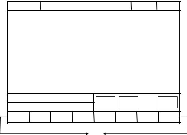
1.2 Screen Sections
The are shown as followings:
1 |
2 |
3 4 |
Screen
5
7
6
(8)
Meanings For Fields on the Display:1 Program Number
2 Title3 Time4 Date5 Data Input
6 Hint7 Status
8 Function Key Switch
- 6 -

CNC Lathe Controller Manual
1.3 Main Menu Selections
The following diagram is the main menu selections for SNC Lathe controller. To operate SNC Lathe controller, users simply make the selections by pressing function keys, F1 F5 located on the bottom of the screen.
- 7 -
CNC Lathe Controller Manual
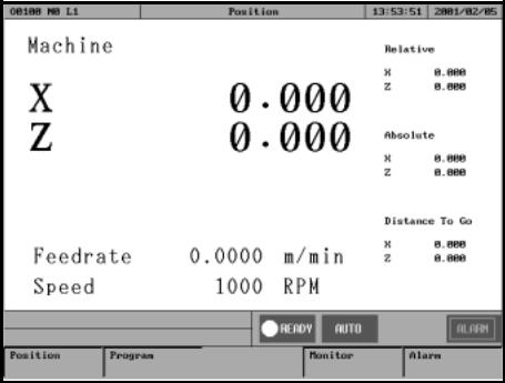
1.3.1 F1 Position
This selection displays coordinate settings of current position. It can also be used to reset the position of relative coordinate. Pressing function key, F1, under the main menu to enter this selection
(Note This is the first screen when the system is booted up)
Meaning of fields on the display------
X X axis coordinate.
Y Y axis coordinate.
Z Z axis coordinate.
Feedrate Feedrate of cutting tool at each machining, mm per minute (mm/min).
Spindle RPM of spindle speed.
Machine(Relative coordinate of working platform)
The current position of cutting tool relative to working platform is shown as machine coordinate on the display.
Relative
The current position of cutting tool relative to the previous location.
Absolute(Programming Coordinate)
The current position of the origin of user defined coordinate is shown as an absolute position on the display.
Distance To Go The distance for the cutting tool to move to the next position in both position(+) and negative(-) direction.
-8 -

CNC Lathe Controller Manual
Function key selections
1.3.1.1 F1 Coor.
Function Switch Coordinate Display
Operation Under the Position submenu, whenever users press F1 key, the values and coordinate on the left corner of the display will toggle among the four different coordinates with bigger fonts as shown in the following figure:
1.3.1.2 F2 1/2 Coor.
Function: Set the center point of work piece as coordinate origin. Operation: Under the Position submenu, when the message line shows “X Input”(or “Y Input” or “Z Input”), press “F2 1/2 Coordinating” and the origin of the coordinate will move to the center point of work piece.
1.3.1.3 F3 Clear Coor.
Function Reset the value of X(or Y or Z) axis relative coordinate to zero.
(No effect on other axis)
Operation Under the Position submenu, when the message line shows “X
Input”(or “Y Input” or “Z Input”), press F3 to reset the value of X(or Y or Z) axis relative coordinate to zero.
- 9 -
CNC Lathe Controller Manual
1.3.1.4 F4 All Clear Relative
Function Reset XYZ relative coordinate to zero.(No effect on other
coordinates)
Operation Under the Position submenu, pressing “F4” will reset XYZ relative coordinate to zero.
1.3.1.5 F5 Worlpiece Coor.
Function Relative to machine coordinate setting for G54~G59.
Operation Under the Position submenu, press "F5 " key and the following screen will show up. By pressing "F1 " key, then users can begin to set the auto machine coordinate settings of G54~G59 one by one. (The system needs to be in manual date input (MDI) mode.)
1. “External Shift” : operator can set the all coordinate G54..G59 at the same time .
2.CNC default G54 ,if user don’t set any G54..G59 in the NC file
-10 -

CNC Lathe Controller Manual
1.3.2 F2 Program
This selection provides users with program file management and editing. With a full screen editor, users can use arrow keys↑ ↓ ← →to move the
cursor to anywhere on the screen for editing purpose. Pressing F2 under the main menu to enter this selection. The full screen editor is shown as follows:
- 11 -

CNC Lathe Controller Manual
Program Sub menu Key Selections:
1.3.2.1 F1 Insert Cycle
Function Insert a block or cycle by conversation
Operation Under Program submenu, press F1 to insert a line or cycle before cursor position.(See Graphic Input Interface(900TE) User Guide)
1.3.2.2 F2 Delete Line
Function Delete a line at cursor position.
operation: Under Program submenu, press F2 to delete a line where the cursor is located.
- 12 -

CNC Lathe Controller Manual
1.3.2.3 F3 Edit Cycle
Function Edit an old block or cycle by conversation input
operation: Under Program submenu, press F3 to edit a line where the cursor is located. .(See Graphic Input Interface(900TE) User Guide)
- 13 -

CNC Lathe Controller Manual
1.3.2.4 F6 EDIT
Function : Edit sub function “ Search “ “Replace” “Goto line” “Copy line””Insert line”
Operation : user can use this menu for more edit sub function
- 14 -

CNC Lathe Controller Manual
1.3.2.4.1 EDIT sub function “F1 : Search”
Function Search String
Operation Under Program submenu, press F6”EDIT” and then F1 “Search” to search string. An dialog box will pop up asking users to input a string as shown in the following figure. After keying in a string, press F1 to start searching.
- 15 -

CNC Lathe Controller Manual
1.3.2.4.2 EDIT sub function “F2 : Replace”
Function Replace String.
Operation Under Program submenu, press F6 “EDIT” and then F2”Replace” to replace string. An dialog box will pop up asking users to input the replacing string and the new string as shown in the following figure. After keying in a string, press F1 to start replacing.
- 16 -

CNC Lathe Controller Manual
1.3.2.4.3 EDIT sub function “F3 : Go To Line”
Function Go to a line number
Operation Under Program submenu, press F6”EDIT” and then F3”GOTO line” to go to the line number. An dialog box will pop up asking users to input a line number. After keying in a number, press F1 to go to the desired line.
1.3.2.4.4 EDIT sub function “F4 : copy line”
Function copy a line from current cursor to next line
Operation Under Program submenu, press F5 “EDIT” and then F4”Copy line” to go to the next line.
1.3.2.4.5 EDIT sub function “F5 : Insert line”
Function Insert a space line above current cursor line Operation Under Program submenu, press F5 “EDIT” and then F5”Insert line” to Insert a new space line
- 17 -

CNC Lathe Controller Manual
1.3.2.5 F7 Teach
Function: Teach now absolute coordinate to NC files Operation Under Program submenu, press F6”Teach”
Teach sub Key Selections
1.3.2.5.1F1 rapid Teach
Function: Add “G00” code to NC files ,G00 to current absolute coordinate,
1.3.2.5.2F2 linear Teach
Function: Add “G01” code to NC files ,G01 to current absolute coordinate,
1.3.2.5.3F3 Arc Teach
Function: Add “G02” or “G03” code to NC files
1st time press this key “arc teach “ ,CNC auto put current value to Arc middle point
2nd time press this key “arc teach “ ,CNC auto calculate G02 or G03 ,and filled the complete code to NC files
- 18 -
CNC Lathe Controller Manual
1.3.2.5.4F4 Cancel Middle
Function: When arc teach ,user can use this key to abort middle point teach .
1.3.2.5.5F5 Delete Line
Function: When user use Teach function , user can use this key “Delete line “ to delete line
- 19 -
CNC Lathe Controller Manual
1.3.2.6 F4 Simulation
Function: Simulating the workpiece program can prove the accuracy of the editing program.
Operation Under Program submenu, press F4
F7 “simulation” sub Key Selections
1.3.2.6.1F1 STEP
Function: To simulate NC files STEP by STEP
Operation: Under Program submenu, press F4”Simulation” and then F1”Step” .The operator can use this function ,to check NC file Step by STEP
1.3.2.6.2F2 Continue
Function: To simulation NC file one time .
Operation: Under Program submenu, press F4 “Simulation” and then F2”Continue” .The operator can use this function to check NC file whole picture ,when push button.
- 20 -
CNC Lathe Controller Manual
1.3.2.6.3 F3 Zoom
Function: To enlarge the workpiece graph.
Operation: Under Program submenu, press F4 and then F3.The operator can use the “←”,”↑”,”→”, ”↓” cursor to move the frame to the determined
area. And use “PageUp” “PageDn” to Enlarge this area .
1.3.2.6.4 F5 Graph reset
Function: To recover the zoomed workpiece graph.
1.3.2.6.5 F6 Abort
Function: To abort simulation action
- 21 -
 Loading...