

Page 1
SYNTE
Date:2014/06/19
6A SERIES
Page 2

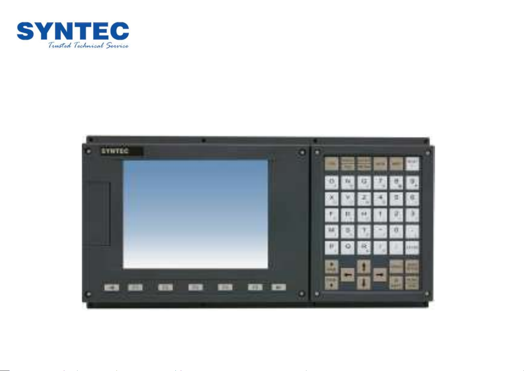
6A Controller
The 6A Architecture
6A Controller Description
The Syntec 6A Series controllers incorporate embedded
system architectures with 8-inch LCD displays and standard
keyboard panels. They include integrated servo axes, spindle
axes, MPG (manual pulse generator) axes, as well as USB ports
on the front panel. This series provides low prices, high
stability, easy operation, and high reliability.
3-axis servo positioning control
2 spindle DA (+/-10V) sets, including 1 encoder set
1 set of dedicated MPG (manual pulse generator) axes,
including 7 IN points
The 6TA and 6MA come standard with 32I/32O, while the 6CA
comes standard with 16I/16O
Standard keyboard panel
Dedicated port on the operation panel for matrix scanning
2 sets of USB ports on the front panel, supporting hot
plug-and-play
Adapter ( 100~240V AC 50/60Hz ) included
Operating environment temperature: 55°C
Page 3
6A Controller
Product Features
Easily Maintainable System Architecture
Complete System Functionality
The system provides complete lathing and milling
functionalities, a simple windows-based operating interface
that is easy to learn to use, and precise synchronous
movement interpolation, allowing users to easily produce
perfected work pieces.
Advanced Transmission Mechanism
In addition to the traditional RS-485 interface, the system also
has an advanced 10/100 MHz Ethernet port as well as
hot-swappable USB ports, which boost software transmission
speeds as well as enhance convenience and stability.
This next-generation controller is built using high-density
integration technologies and incorporates an extremely
well-thought-out design. Its compact and modular design
allows on-site personnel to easily perform maintenance with
just a single screwdriver.
Page 4
6A Controller
Multi-pocketed Complex Cutting cycle
-The user only needs to enter the external appearance
of the work piece, and the CNC will automatically
figure out the cutting path and cycle
-Can be used with A, R, and C
-Can perform multi-pocketed processing with one run
of the program
Graphical Dialogue
-X/Y axis single/dual-direction surface milling
cycles
-Track-type/square-type/round-type trench
rocessing cycles
-Round-hole/angled-line hole/curved-hole
checkerboard hole drilling cycles
Processing execution
-Integrated operation environment
-Processing parameter configuration
-Program coordinate and cutting tool
configurations are made on the same page
Hand Wheel Processing Simulation
The MPG can be used to control software processing speeds
Rotate the MPG forwards/backward to move the cutting tool
forwards/backwards along its path
Turn the MPG to fast and the cutting tool will move faster along its path
Turn the MPG to slow and the cutting tool will move slower along its path
Turn the MPG to stop and the machine will stop
On line ladder
-I, O, C, S inspection page
-Real-time Ladder display
-Search for components
-The PLC can issue alert messages in
Chinese and English
Alert records
-Records 200 alert messages in the alert history, with
dates, hours, minutes, seconds, and alert content
-Capable of further displaying reason for malfunction and
methods used for troubleshooting
Parameter Settings
-Parameter group configuration
-Comprehensive descriptions of the
meaning of parameters
-Password protection
-Supports user-defined parameters
Production Records
-Provides complete records for 100 completed processing
programs, including the program name, start time, total
processing time, as well as number of work pieces
-Monitors the production rate of programs in execution
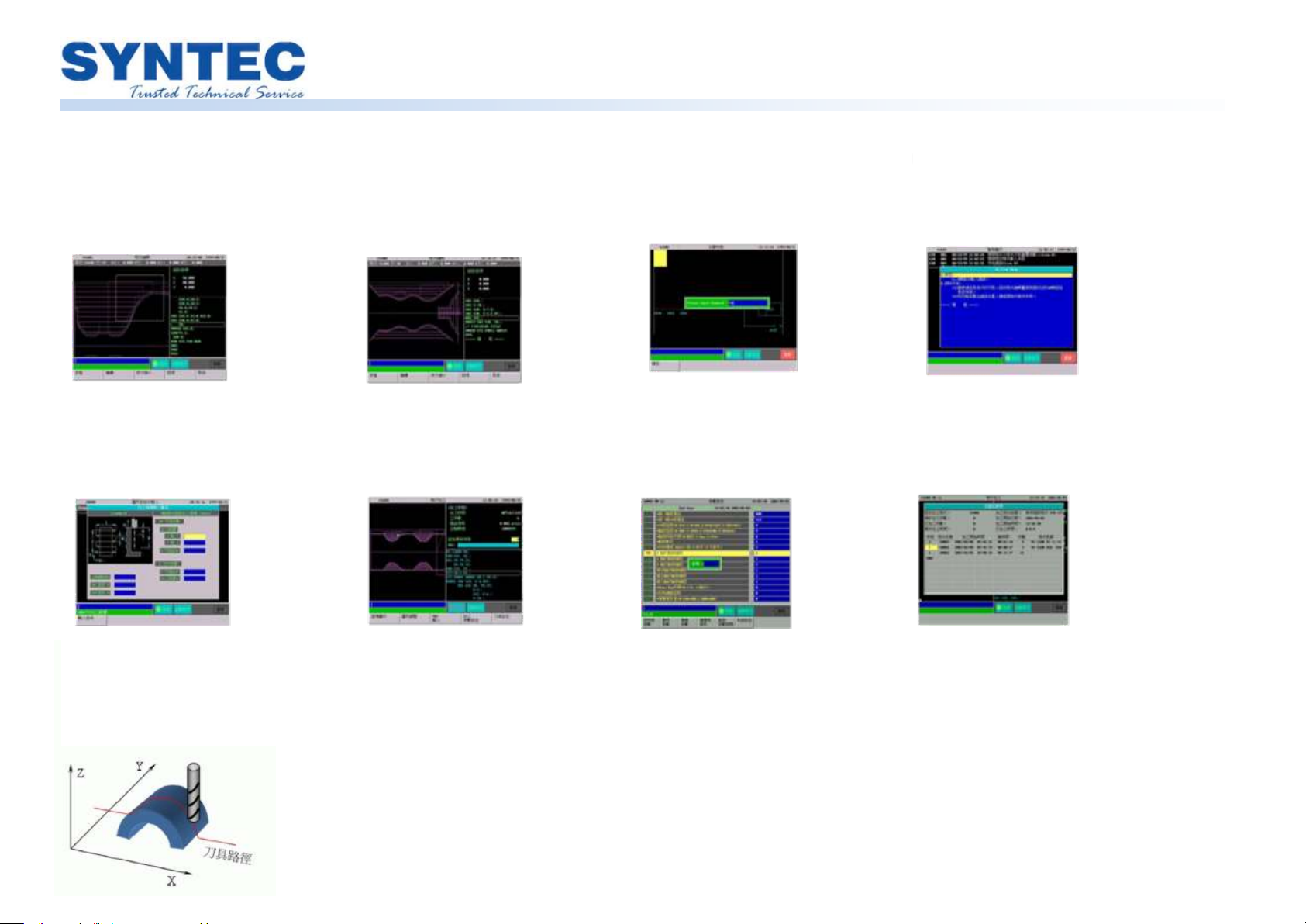
Simulation
– Syntax check
– 3D simulation and step simulation
– Magnify at any ratio
– Integrated environment that can also check
trajectory coordinates and program contects
User-Friendly Operation Interface
Thoughtful Diagnostic and Development Tools
Page 5

6A Controller
Logic Computation Command
Digit Function Command
Structural Process Control Command
MACRO Support
-Windows based Macro development environment
-Can communicate with the PLC via register bits
-Completely compatible with CNC operating
environments
-Open and store files
-Step simulation and three-view diagram
simulation
-System parameter and variable configuration
Ladder Support
-Windows based PLC software development
-Online Ladder display, making troubleshooting
easier
-PLC executes servo movement commands
-Editing Function Table
Open file, save file
Add Ladder footnote (Chinese and English)
Cut, copy, paste
Search,…
Syntax check
Contact point: normally open,
normally closed
Coil: normally open, normally
closed, positive edge, negative
edge, always return
Arithmetic commands:
Timer, counter
Data movement: MOV
Cutting tool commands: ROT
Software control commands:
JMP, JSR
Call subroutine
Directly execute PLC shaft
movement commandSpecify
PLC shaft for executing
movement program
instruction…………………..
Macro Syntax
Ladder Syntax
Complete Software Application Support
Page 6
6A Controller
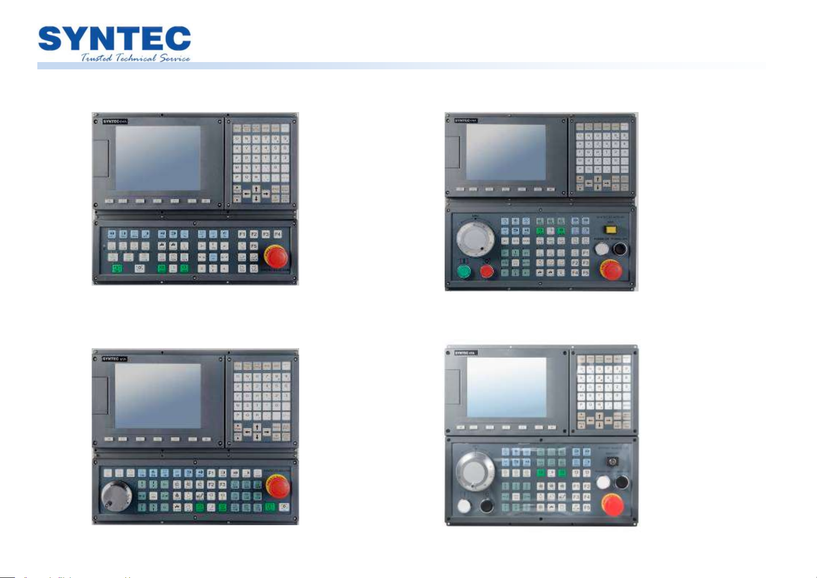
External Appearance of the Product (6A-4012-M)
External Appearance of the Product (6A-4012-T2)
External Appearance of the Product (6A-4018-M2)
External Appearance of the Product (6A-4018-T3)
Page 7

6A Controller
Structural Dimensions (6A-4012-M)
Structural Dimensions (6A-4012-T2)
Page 8
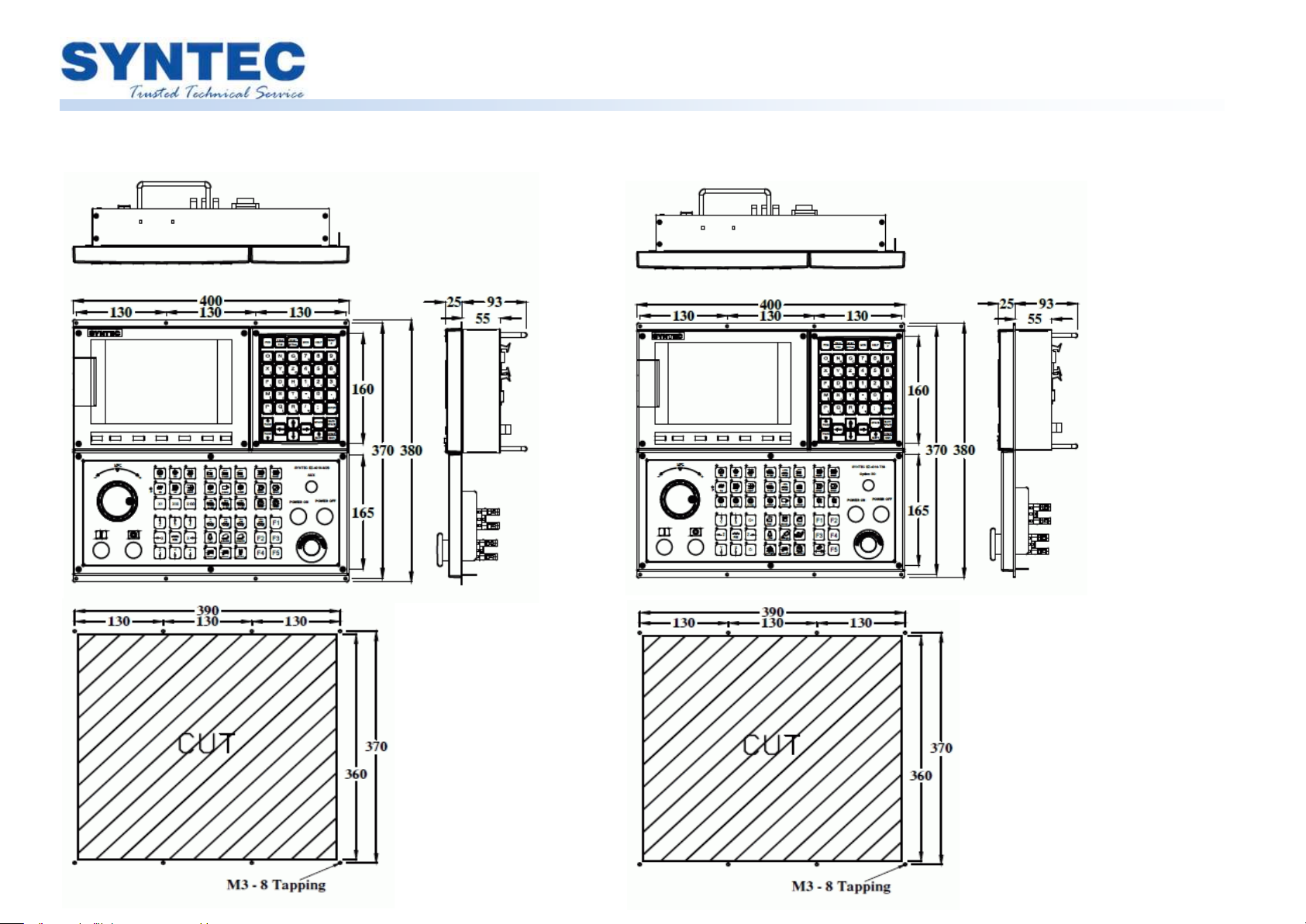
6A Controller
Structural Dimensions (6A-4018-M2)
Structural Dimensions (6A-4018-T3)
Page 9

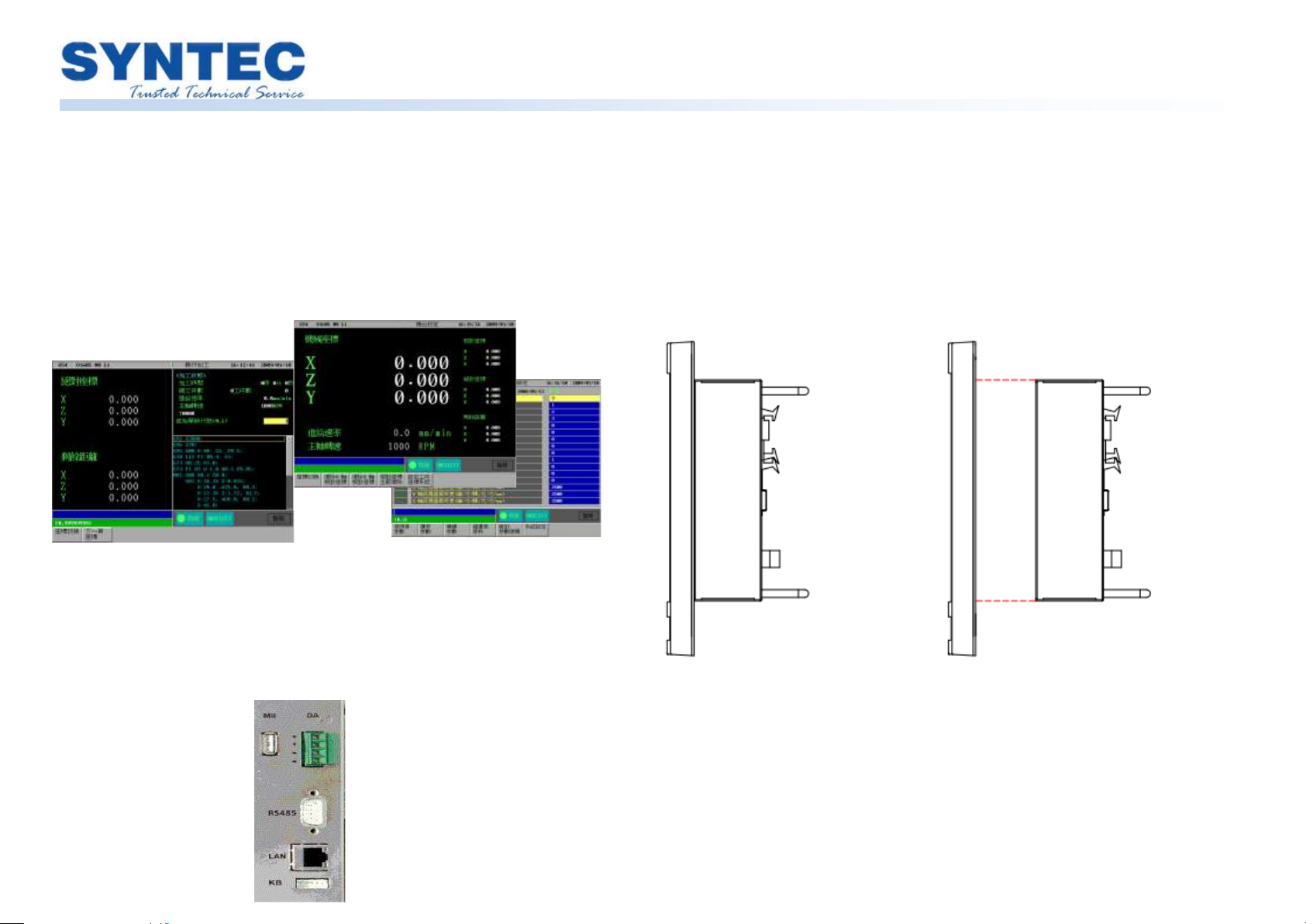
6A Controller
WWiirriinngg--SSiiddee RRSS448855 FFrroonntt
SScchheemmaattiicc DDiiaaggrraam
m
Connector Interface Definitions
Please mind the voltage values as well as positive and negative
polarities
X1 Connector Definitions Y1 Connector Definitions
HK Connector Definitions Spindle Connector Definitions
P1~P3 Connector Definitions
SP Connector Definitions
RS485 Connector Definitions
MPG Connector Definitions
Page 10

6A Controller
Product Specifications
Model
6TA
6CA
6MA
Control command format
Generic
6CA
6MA
Largest main system axis group
2 1 2
Largest PLC axis group number
1 ─ 1
Standard control axis number
3
Maximum control axis number (optional)
3
Maximum spindle number
2 1 1
Maximum synchronous control axis number
(single axis group)
3 2 3
Smallest unit of control - mm
0.0001
Maximum number of work piece coordinate sets
32
Maximum number of tool compensation sets
96
Number of pre-read single-sections
64
100
100
Single-section processing time – number of single
sections / seconds
300
350
350
Hardware Specifications
I/O (standard)
32/32
16/16
32/32
I/O (optional)
─
DA
2
Display
8
RJ-45
1
VGA output
─
PS/2
─
RS232/RS422/RS485
─/─/1
CF card
─
USB
2
Compensation
Model
6TA
6CA
6MA
Backlash compensation
O
Pitch error compensation
O
Angle compensation
O
Temperature-rise compensation
O
Two-dimensional compensation
─
Operation
MPG simulation
O
Program idle
O
Selective stop
O
Single-section execution
O
Virtual MPG
O
Pause point activation
O
Break point activation
O
External offset settings
O
MPG offset function
─ O O
Program Input
Selective jump
O
B-stop / end of program
O
Interrupt-type MACRO (M96/M97)
─
M198 subroutine call
─
G code expansion
O
6A Series Product Specifications
O Standard
-
Not supported
△
Optional
Page 11

6A Controller
High-Speed, High-Precision
Model
6TA
6CA
6MA
Constant Jerk control
O
Cross-section S-curve acceleration and deceleration
─
Automatic corner deceleration
O
Circular radius speed limit
O
Multiple sets of high-speed high-precision
parameters
─
Fast user parameters
─
SPA function
─
Virtual circular radius function
─
High-speed high-precision control mode I (G05.1Q1)
─
High-speed high-precision control mode II
(G05P10000)
─
NURBS interpolation
─
Tool and Blade Management
Automatic blade calibration
─ O O
Tool and blade usage life management
O
Supportive Functions
Mechanical lock (R-bit)
O
Software cycle limit
O
Spindle rotation speed detection
O
Axial coupling function
─ O O
Dynamic axial coupling function
─
Feedback coupling function
─
Fast tapping retraction
O
Virtual axis function
─
Axis swapping function
─
Serial machine swapping function
─
Fast controller-based spindle positioning (C61)
─ O O
Frond and back Dipole architecture
─
Data backup and restoration (MB)
O
Boot screen customization
O
Favorites
─
Project protection function
─
Access privilege management
─
RemoteAP monitoring
O
Programming
Background editing
O
Editing protection
O
Data Transfer Function
NETWORK/FTP
O/O
DNC(Network)
O
DNC(USB)
─
Information Display
Graphical simulation
O
Optical scale missing pulse self-diagnostics
─
Five-Axis Function
Five-axis blade tip control (RTCP)
─
Smooth blade tip function (Smooth TCP)
─
Tilted-Surface
Characteristic coordinate system (tilted-surface
processing) (G68.2)
─
Characteristic coordinate system training
─
Page 12
6A Controller
G Code Commands
Model
6TA
Elliptical cutting (clockwise) (G02.1)
O
Parabolic cutting (clockwise) (G02.2)
O
Cylindrical interpolation (G07.1)
O
Activate polar coordinate interpolation (G12.1)
O
External radius / internal radius lathing and cutting cycle (G20)
O
Threaded lathing and cutting cycle (G21)
O
Threaded lathing and cutting mid-phase blade entry cycle (G21.2)
O
Edge and surface lathing and cutting cycle (G24)
O
Jumping function (G31)
O
Thread cutting (G33)
O
Variable-pitch thread cutting (G34)
O
Blade tip control (G43.4)
─
Polygonal cutting (G51.2)
O
Blade calibration for tilted surface processing (G53.1)
─
Operating coordinate system configuration (G54~G59.9)
O
Mirroring function (lathe) (G68)
O
Tilted surface processing (G68.2)
─
Duplex cutting cycles (G72~G78)
O
Fixed drilling cycles (G80,G83~G89)
O
Default absolute zero coordinated system (G92.1)
O
Inversed time feed (G93)
O
Equal surface cutting speeds (G96)
O
Spindle synchronization function (G114.1)
O
Spindle bearing function (G114.3)
O
Model
6CA
6MA
High-speed high-precision mode (G05)
─
Path smoothing mode (G05.1)
O
NURBS curve interpolation (G06.2)
─
Thread cutting (G33)
O
Automatic blade measurement command (G37)
─
Blade offset (G45~G48)
─
Tilted surface processing (G68.2)
─
High-speed pecking-type drilling cycle (G73)
O
Left-handed tapping cycle (G74)
O
Fine boring cycle (G76)
O
Drilling cycle (G81)
O
Suspended hole-bottom drilling cycle (G82)
O
Pecking-type drilling cycle (G83)
O
Tapping cycle (G84)
O
Drilling cycle (G85)
O
High-speed drilling cycle (G86)
O
Backside fine boring cycle (G87)
O
Semi-automatic fine boring cycle (G88)
O
Suspended hole-bottom boring cycle (G89)
O
Page 13
6A Controller
Model
6A
Operating environment
-10 ~ 55oC
Storage environment
-40 ~ 70oC
Cooling method
Natural cooling
Safety certification
CE
Operating voltage
100V~240V, 60Hz
Power consumption
Approximately 5W
6A Series Operating Environment
 Loading...