


Synology DiskStation DS2419+
Hardware Installation Guide

Table of Contents
Chapter 1: Before You Start
Package Contents 3
Synology DiskStation at a Glance 4
Safety Instructions 5
Chapter 2: Hardware Setup
Tools and Parts for Drive Installation 6
Install Drives 6
Start Up Your DiskStation 9
Add a RAM Module on DiskStation 10
Add a Network Interface Card 13
Replace System Fan 16
Chapter 3: Install DSM on DiskStation
Install DSM with Web Assistant 17
Learn More 17
Appendix A: Specications
Appendix B: LED Indicator Table
Synology_HIG_DS2419+_20180419
2
Chapter
Before You Start
Thank you for purchasing this Synology product! Before setting up your new DiskStation, please check the
package contents to verify that you have received the items below. Also, make sure to read the safety instructions
carefully to avoid harming yourself or damaging your DiskStation.
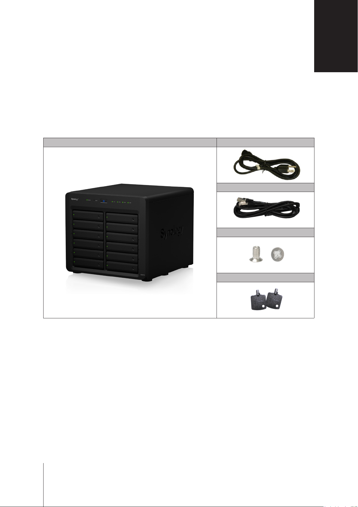
Package Contents
Main unit x 1 AC power cord x 1
RJ-45 LAN cable x 2
1
Screws for 2.5” drives x 52
Drive tray key x 2
3
3
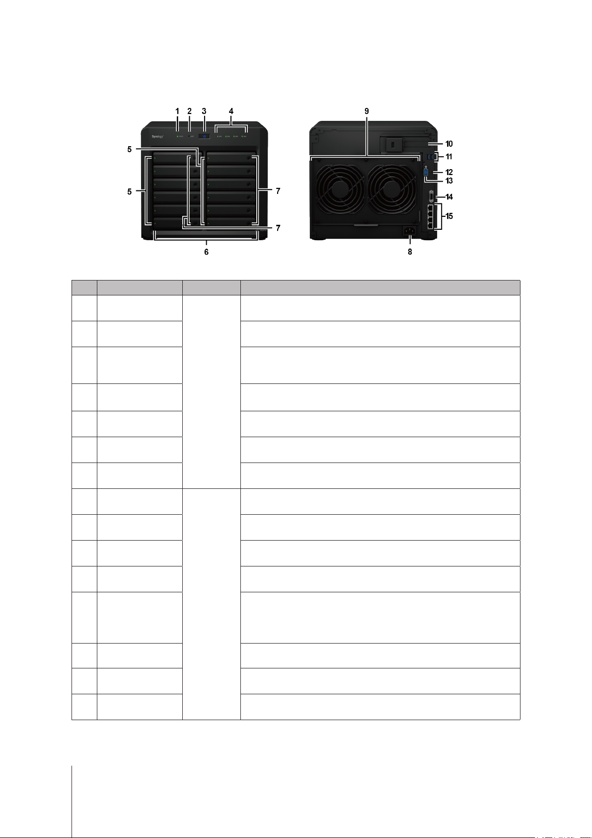
Synology DiskStation at a Glance
No. Article Name Location Description
1
2
3
4
5
Status Indicator
Alert Indicator
Power Button
LAN Indicator
Drive Status Indicator
Front Panel
Displays the status of the system. For more information, see "Appendix B:
LED Indicator Table".
Displays warnings regarding fan or temperature. For more information, see
"Appendix B: LED Indicator Table".
1. Press to power on the DiskStation.
2. To power o the DiskStation, press and hold until you hear a beep sound
and the Power LED starts blinking.
Displays the status of the network connection. For more information, see
"Appendix B: LED Indicator Table".
Displays the status of the installed drive. For more information, see "Appendix
B: LED Indicator Table".
6
7
8
9
10
11
12
13
14
15
Drive Tray Install drives (hard disk drives or solid state drives) here.
Drive Tray Lock Lock or unlock drive trays.
Power Port
Fan
PCI Express
Expansion Slot
USB 3.0 Port Connect external drives or other USB devices to the DiskStation here.
Back Panel
RESET Button
Console Port This port is used for manufacturing use only.
Expansion Port Connect Synology Expansion Unit1 to the DiskStation here.
LAN Port Connect network cables here.
Connect the AC power cord here.
Disposes of excess heat and cools the system. If the fan malfunctions, the
DiskStation will emit a beeping sound.
Supports one PCIe x8 slot (x4 link) add-on card.
1. Press and hold until you hear a beep sound to restore the default IP
address, DNS server, and password for the
2. Press and hold until you hear a beep sound, then press and hold again
until you hear three beep sounds to return the DiskStation to “Not Installed”
status so that DiskStation Manager (DSM) can be reinstalled.
admin
account.
1
For more information about Synology Expansion Unit supported by your DiskStation, please visit
4 Chapter 1: Before You Start
www.synology.com
.
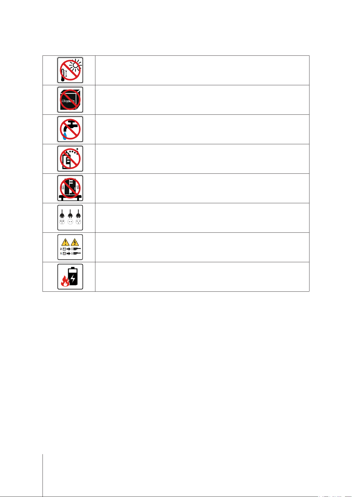
Safety Instructions
Keep away from direct sunlight and away from chemicals. Make sure the environment does not
experience abrupt changes in temperature or humidity.
Place the product right side up at all times.
Do not place near any liquids.
Before cleaning, unplug the power cord. Wipe with damp paper towels. Do not use chemical or
aerosol cleaners.
To prevent the unit from falling over, do not place on carts or any unstable surfaces.
The power cord must plug in to the correct supply voltage. Make sure that the supplied AC voltage is
correct and stable.
To remove all electrical current from the device, ensure that all power cords are disconnected from
the power source.
Risk of explosion if battery is replaced with an incorrect type. Dispose of used batteries appropriately.
5 Chapter 1: Before You Start

Chapter
Hardware Setup
Tools and Parts for Drive Installation
• A screwdriver (only for 2.5” drives)
• At least one 3.5” or 2.5” SATA drive (please visit
Warning:
back up any important data before installation.
If you install a drive that contains data, the system will format the drive and erase all existing data. Please
Install Drives
1
Press the right part of the drive tray to pop out the handle.
www.synology.com
2
for compatible drive models.)
6
2
Pull the drive tray handle in the direction as indicated below to remove the drive tray.

3
Load drives in the drive trays.
For 3.5” drives:
•
tray. Then insert the fastening panels to secure the drive in place.
For 2.5” drives:
•
place. Place the drive in the blue area (shown below) of the drive tray. Turn the tray upside down and tighten
the screws to secure the drive in place.
Remove the fastening panels from the sides of the drive tray. Place the drive in the drive
Remove the fastening panels from the sides of the drive tray and store them in a safe
4
Insert the loaded drive tray into the empty drive bay.
Note:
Make sure the tray is pushed in all the way. Otherwise, the drive might not be able to function properly.
5
Press the handle in ush with the front panel to hold the drive tray in place.
7 Chapter 2: Hardware Setup

6
Insert the drive tray key into the drive tray lock, turn the key clockwise (to the “-” position) to lock the handle of
the drive tray, and then remove the key.
7
Repeat the steps above to assemble the other drives you have prepared.
8
Drives are numbered as shown below.
Note:
If you want to create a RAID volume, we recommended that all installed drives are of the same size to make the
best use of drive capacity.
8 Chapter 2: Hardware Setup

Start Up Your DiskStation
1
Use the LAN cable to connect the DiskStation to your switch, router or hub.
2
Connect one end of the AC power cord to the power port of the DiskStation, and the other to the power outlet.
3
Press the power button.
Congratulations! Your DiskStation is now online and detectable from a network computer.
9 Chapter 2: Hardware Setup

Add a RAM Module on DiskStation
The optional Synology DDR4 RAM module is designed for DiskStation memory expansion. Follow the steps
below to install, check, or remove a RAM module on your DiskStation.
To install the RAM module:
1
Press and hold the power button until you hear a beep sound to shut down your DiskStation. Disconnect all
cables from your DiskStation to prevent any possible damage.
2
Remove the side panel:
a
Remove the 2 screws on the back of DiskStation.
b
Pull the side panel. Place the side panel to the side.
Note:
When you remove the case, you expose sensitive internal components. Avoid touching anything other than the
memory assembly when you remove or add memory.
10 Chapter 2: Hardware Setup

3
Insert the new RAM module in the slot:
a
Align the notch on the gold edge of the module with the notch in the memory slot. Then tilt the card and
insert the module into the slot. Make sure the module is properly inserted.
b
Push the RAM module with moderate pressure into the memory slot until you hear a click.
Note:
• Hold the memory module by its edges, and do not touch the gold connectors.
• When memory capacity is changed, the device will perform a memory check upon the next start up. This will
prolong the start up time by up to ten minutes. This behavior is normal and will only occur once.
4
Replace the side panel. Replace and tighten the 2 screws you removed in step 2-a.
11 Chapter 2: Hardware Setup

To make sure DiskStation recognizes the new memory capacity:
1
Install DiskStation Manager (DSM). (See the next chapter for more information.)
2
Log in to DSM as
3
If your DiskStation fails to either recognize the memory or start up successfully, conrm that the memory has
been properly installed.
To remove the RAM Module:
1
2
3
Total Physical Memory
Check
Follow step 1 to 3 of the "To install the RAM module" section to shut down your DiskStation, disconnect the
cables, and then remove the bottom lid.
Push the levers on both sides of the memory module outwards. The module will be released from the slot.
Hold the memory module by its notches and remove it from the slot.
admin
or a user belonging to the
Control Panel
in
administrators
Info Center
>
group.
.
4
Replace the side panel. Replace and tighten the screws you removed in the initial step.
12 Chapter 2: Hardware Setup
Add a Network Interface Card
Your DiskStation has a PCI Express expansion slot which allows you to install 10GbE or Gigabit network interface
card for LAN port expansion.1 You need to replace the long bracket (suited for PC) of your network interface card
with a short bracket before installing the card into your DiskStation.
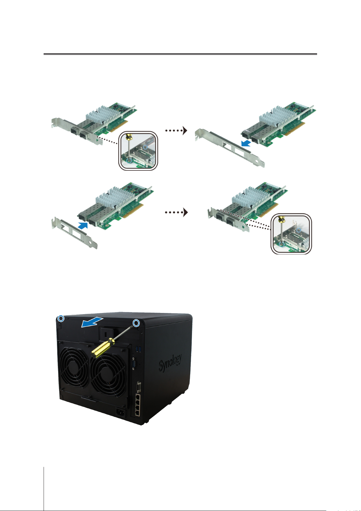
To replace a long bracket with a shor t one:
1
Remove the 2 screws from the long bracket of your network interface card, and then remove the bracket.
2
Replace the long bracket with a short one, and tighten the 2 screws to secure the short bracket.
To install a network interface card:
1
Press and hold the power button until you hear a beep sound to shut down your DiskStation. Disconnect all
cables from your DiskStation to prevent any possible damage.
2
Remove the 2 screws on the top of the back panel, and then pull the top cover in the direction as illustrated
below.
1
For more information about supported 10GbE or Gigabit network interface cards, please visit
13 Chapter 2: Hardware Setup
www.synology.com
.

3
Remove the PCIe expansion slot shield:
a
Reposition your DiskStation so that the top will be facing your body, with drive trays on the right side.
b
Pull the clip above the PCIe expansion slot shield in the direction as illustrated below.
c
Remove the shield.
4
Install the network interface card:
a
Align the card’s connectors with the PCIe expansion slot.
14 Chapter 2: Hardware Setup

b
Use two ngers with rm, even pressure to push down on the card and the bracket.
c
Push back the clip to secure the newly inserted card.
Note:
Make sure the connectors are fully inserted. Otherwise, the network interface card might not be able to function
properly.
5
Replace the top cover, and then replace and tighten the 2 screws you removed in Step 2.
15 Chapter 2: Hardware Setup

Replace System Fan
Your DiskStation will play beep sounds if either of the system fans is not working. Follow the steps below to
replace the malfunctioning fan module with a good one.
To replace the system fan module:
1
Shut down your DiskStation. Disconnect all cables connected to your DiskStation to prevent any possible
damages.
2
Pull the 6 push pins that secure the fan module.
3
Pull out the malfunctioning fan module to remove it from your DiskStation.
4
Install the new fan module:
a
Install the new module with the power connector at the bottom, so that it can be properly put onto the
chassis.
b
Make sure that all 6 push pins on the new module are pulled outwards before the module is placed into your
DiskStation, and then press the push pins back into place to secure the fan module.
16 Chapter 2: Hardware Setup

Chapter
Install DSM on DiskStation
After hardware setup is nished, please install DiskStation Manager (DSM) – Synology’s browser-based
operating system – on your DiskStation.
Install DSM with Web Assistant
Your DiskStation comes with a built-in tool called
DSM from the Internet and install it on your DiskStation. To use Web Assistant, please follow the steps below.
1
Power on the DiskStation.
2
Open a web browser on a computer connected to the same network as the DiskStation.
3
Enter either of the following into the address bar of your browser:
a nd.synology.com
b diskstation:5000
4
Web Assistant will be launched in your web browser. It will search for and nd the DiskStation within the local
network. The status of the DiskStation should be
Web Assistant
Not Installed
that helps you download the latest version of
.
3
5
6
Connect
Click
Note:
1. The DiskStation must be connected to the Internet to install DSM with Web Assistant.
2. Suggested browsers: Chrome, Firefox.
3. Both the DiskStation and the computer must be in the same local network.
If you accidentally leave the installation process before it is nished, login to the DSM as
administrative account name) with the password left blank.
to start the setup process and follow the onscreen instructions.
admin
(default
Learn More
Congratulations! Your DiskStation is now ready for action. For more information or online resources about your
DiskStation, please visit
17
www.synology.com
.

Appendix
Specications
Item DS2419+
Internal Drives 3.5" or 2.5" SATA x 12
Max. Capacity
External Device Ports
LAN Ports Gigabit x 4
PCIe Slot PCIe 3.0 x8 slot (x4 link) add-on card (optional)
Size (H x W x D) (mm) 270 x 300 x 340
Weight (kg) 9.5
Supported Clients
File Systems
Supported RAID Types
• Synology Hybrid RAID (Up to 2-Disk Fault Tolerance)
Agency Certications • FCC Class B • CE Class B • BSMI Class B • EAC • VCCI Class B • RCM •CCC
HDD Hibernation Ye s
Scheduled Power On/O Yes
Wake on LAN Yes
• 168 TB (12 x 14 TB drives)
• 336 TB with DX1215 (expansion unit)
• USB 3.0 x 2
• Expansion port x 1
• Windows 7 and 10
• Mac OS X 10.11 onward
• Internal: EXT4, Btrfs
• External: EXT4, EXT3, FAT, NTFS, HFS+
• Basic • JBOD • RAID 0 • RAID 1
• RAID 5 • RAID 6 • RAID 10
A
18
Language Localization
Environment Requirements
Note:
Model specications are subject to change without notice. Please refer to
• Line voltage: 100V to 240V AC
• Frequency: 50/60Hz
• Operating Temperature: 32 to 104˚F (0 to 40˚C)
• Storage Temperature: -5 to 140˚F (-20 to 60˚C)
• Relative Humidity: 5% to 95% RH
www.synology.com
for the latest information.

Appendix
LED Indicator Table
LED Indicator Color Status Description
Green Static Volume normal
STATUS
ALERT
Power
Front LAN
Orange Blinking
Red Blinking Fan failure / Over temperature
Blue
Green
Orange
Green Static Gigabit connection
B
Volume degraded / Crashed
Volume not created
DSM not installed
O HDD hibernation
O System normal
Static Powered on
Blinking Booting up / Shutting down
O Powered o
Static Gigabit connection
Blinking Gigabit network active
Static 100 Mbps connection
Blinking 100 Mbps network active
10 Mbps connection
O
No network
Rear LAN
(on upper side of jack)
Rear LAN
(on lower side of jack)
Drive Status Indicator
(on tray)
Note:
Model specications are subject to change without notice. Please refer to
Orange Static 100 Mbps connection
Green
Green
Orange Static Drive error
O
Static Network connected
Blinking Network active
O No network
Static Drive ready and idle
Blinking Accessing drive
O No internal drive
www.synology.com
for the latest information.
10 Mbps connection
No network
19
 Loading...