

Page 1
How to Replace Hard Disk Backplane
for 8 bay/5 bay DiskStation
Revision 1.0
THIS DOCUMENT CONTAINS PROPRIETARY
TECHNICAL INFORMATION WHICH IS THE
PROPERTY OF SYNOLOGY INCORPORATED AND
SHALL NOT BE DISCLOSED TO OTHERS IN
WHOLE OR IN PART, REPRODUCED, COPIED, OR
USED AS THE BASIS FOR DESIGN,
MANUFACTURING, OR SALE OF APPARATUS
WITHOUT WRITTEN PERMISSION OF SYNOLOGY
INCORPORATED.
Page 2
How to Replace Hard Disk Backplane for 8 bay/5 bay DiskStation
Table of Content
1. Introduction ................................................................................................................. 3
1.1 Applied Models & Required Components .......................................................... 3
1.2 Required Tools ................................................................................................... 4
2. Start to Replace .......................................................................................................... 5
2.1 Dismantle the defective HDD backplane ............................................................ 5
2.2 Install the replacement HDD backplane ........................................................... 22
Revision History
Revision
Number
v.1.0 2014/4/11 Initial version Dennis Tang
Date: 2014/4/11
Issued by: Hardware Development Group, Synology ® Inc.
Date of Issue Summary of Change By
Page 2 of 39
Page 3
How to Replace Hard Disk Backplane for 8 bay/5 bay DiskStation
1. Introduction
This SOP explains about the detailed steps for replacing hard disk backplane (“HDD
backplane”) on Synology’s 8 bay/5 bay DiskStation products.
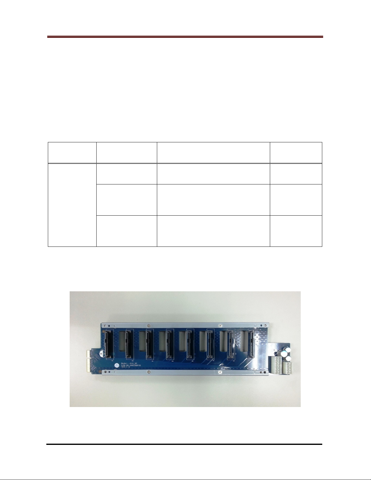
1.1 Applied Models & Required Components
HDD backplane of the DiskStation model for replacing:
Required
Module
SATA
Backplane
Note: For DX513, consult Synology for further information about the correct
backplane version before proceeding to replace.
Item Code Description Applied Model
80-18TBP0010
ASSY PCBA DS1812+ BP
SYNOLOGY V1.0
ASSY PCBA DS1512+ SATA
80-1512PSB11
BOARD SYNOLOGY V1.1
ASSY PCBA DS1010+ SATA
80-D510PSB14
BOARD SYNOLOGY V1.4
DS1813+
DS1812+
DS1513+
DS1512+
DX513 (*)
DS1511+
DX513 (*)
DX510
HDD Backplane for DS1813+ (Metal Frame Included)
Page 3 of 39
Date: 2014/4/11
Issued by: Hardware Development Group, Synology ® Inc.
Page 4
How to Replace Hard Disk Backplane for 8 bay/5 bay DiskStation
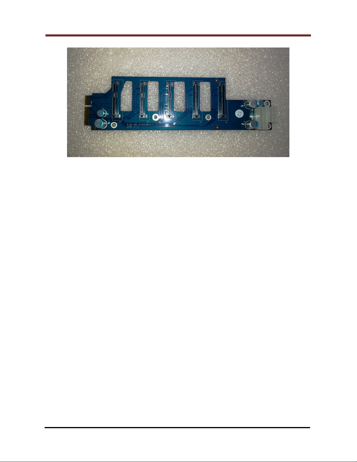
HDD Backplane for DS1513+
1.2 Required Tools
Screw Driver “+” Type: Suggested Bit Size PH#2
Note: If an automatic screwdriver is used, set its torque reading to be 4.5 (+/-0.2)
kg/cmf in advance.
Anti-static / Cotton Gloves
Date: 2014/4/11
Issued by: Hardware Development Group, Synology ® Inc.
Page 4 of 39
Page 5
How to Replace Hard Disk Backplane for 8 bay/5 bay DiskStation
Fan Panel
Rear Panel
Fan #1
Fan #2
Fan Panel
Enclosure
2. Start to Replace
Note: DS1813+ is hereunder the common example unless otherwise specified.
2.1 Dismantle the defective HDD backplane
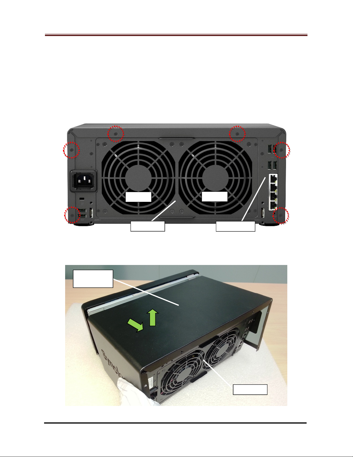
2.1.1 Release the six (6) screws on the rear panel (Marked by the red circles). (Fig. 1)
Fig. 1
2.1.2 Draw backwards then move up the enclosure cover to remove it. (Fig. 2)
Cover - Top
Fig. 2
Page 5 of 39
Date: 2014/4/11
Issued by: Hardware Development Group, Synology ® Inc.
Page 6
How to Replace Hard Disk Backplane for 8 bay/5 bay DiskStation
Fan Panel
Rear Panel
Fan #1
Fan #2
Enclosure
- Bottom
Rear Panel
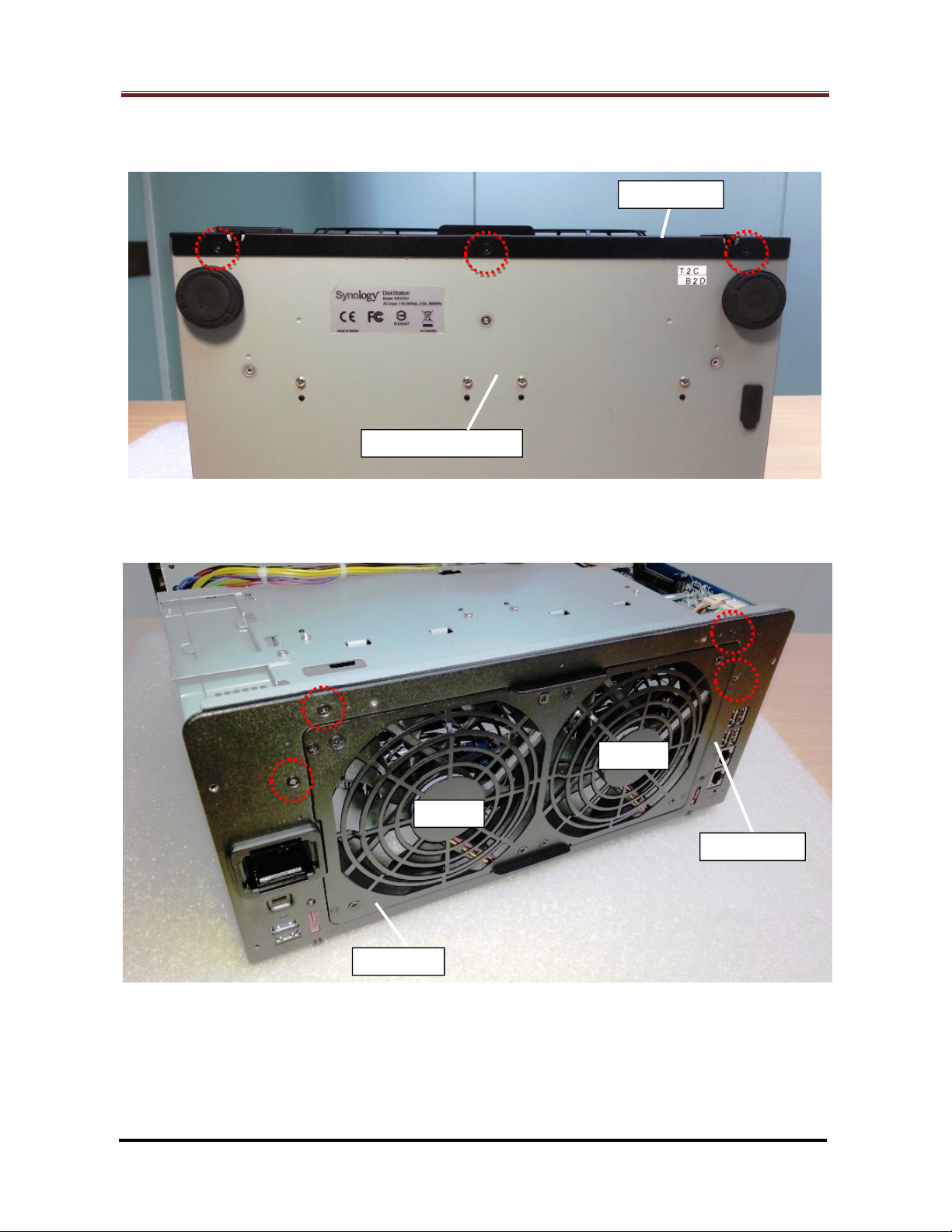
2.1.3 Release the three (3) screws on the enclosure bottom (Marked by the red circles).
(Fig. 3)
Fig. 3
2.1.4 Release the four (4) screws on the rear panel (Marked by the red circles). (Fig. 4)
Fig. 4
Date: 2014/4/11
Issued by: Hardware Development Group, Synology ® Inc.
Page 6 of 39
Page 7
How to Replace Hard Disk Backplane for 8 bay/5 bay DiskStation
Rear Panel
Fan Cable
Connector #1
Fan Cable
Connector #2
eSATA Board
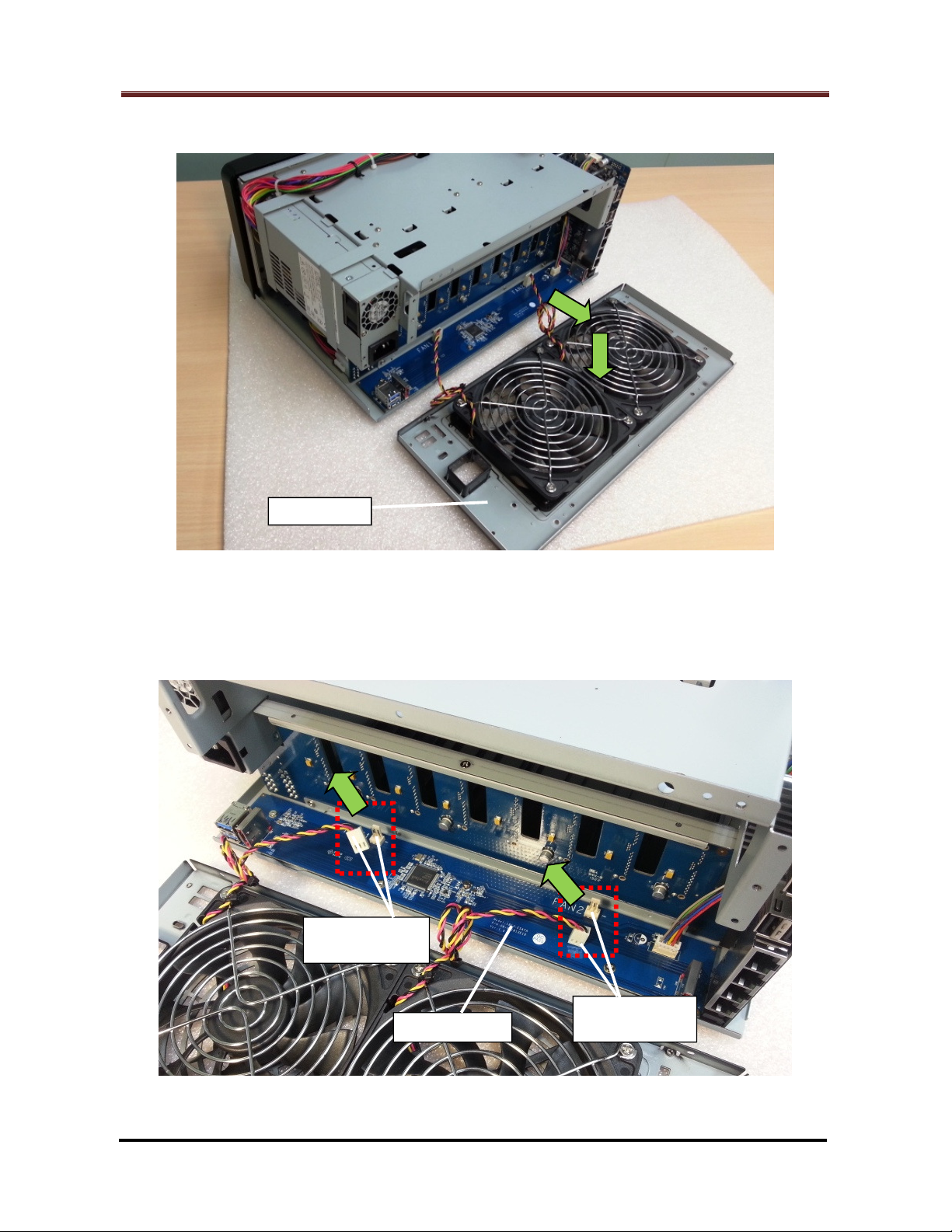
2.1.5 Remove the rear panel from the enclosure. (Fig. 5)
Fig. 5
2.1.6 Unplug the two (2) fan cable connectors (Marked by the red rectangles) which
attach to the eSATA board. (Fig. 6)
Fig. 6
Page 7 of 39
Date: 2014/4/11
Issued by: Hardware Development Group, Synology ® Inc.
Page 8
How to Replace Hard Disk Backplane for 8 bay/5 bay DiskStation
Front
Panel
Disk
Tray
Enclosure
- Bottom
Rear Panel
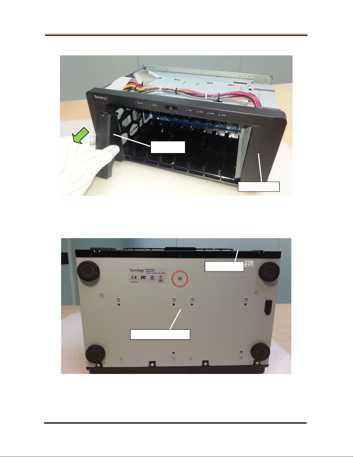
2.1.7 Remove all the disk trays from the HDD chassis. (Fig. 7)
2.1.8 For DS1813+, DS1812+:
Release the screw on the enclosure bottom (Marked by the red circles). (Fig. 8)
Fig. 7
Fig. 8
Date: 2014/4/11
Issued by: Hardware Development Group, Synology ® Inc.
Page 8 of 39
Page 9
How to Replace Hard Disk Backplane for 8 bay/5 bay DiskStation
Enclosure
- Top
Motherboard
eSATA Board
Cable Connector
Rear Panel
Enclosure
- Top
Motherboard
eSATA Board
Cable Connector
Rear Panel
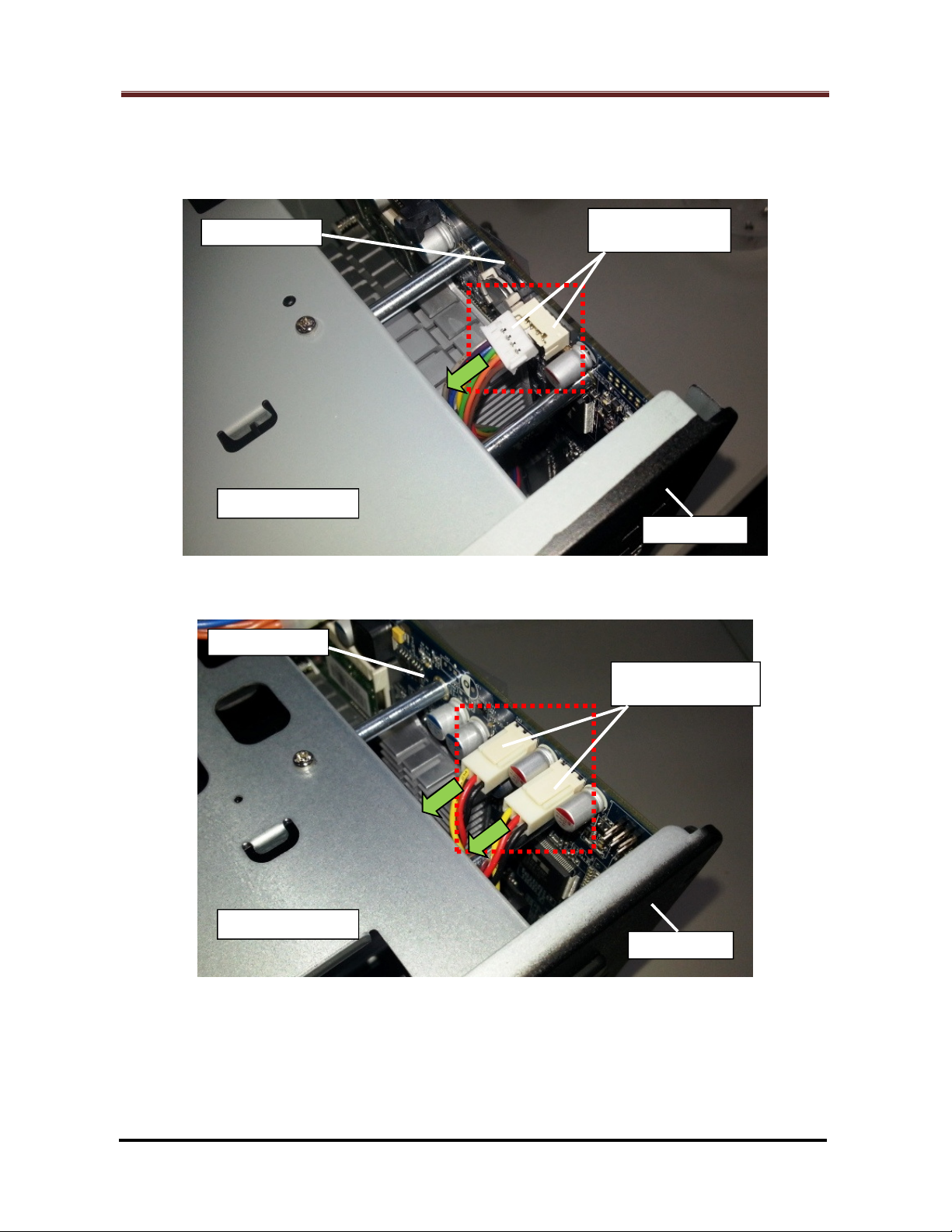
2.1.9 Unplug the eSATA board cable connector(s) (Marked by the red rectangle) from the
motherboard. (Fig. 9 for DS1813+, DS1513+, DX513 and Fig. 10 for DS1812+,
DS1512+, DS1511+, DX513 and DX510):
Fig. 9 – For DS1813+, DS1513+, DX513
Fig. 10 – For DS1812+, DS1512+, DS1511+, DX513, DX510
Page 9 of 39
Date: 2014/4/11
Issued by: Hardware Development Group, Synology ® Inc.
Page 10
How to Replace Hard Disk Backplane for 8 bay/5 bay DiskStation
Front Panel
Isolating Mylar
(Transparent)
Enclosure
- Top
Motherboard
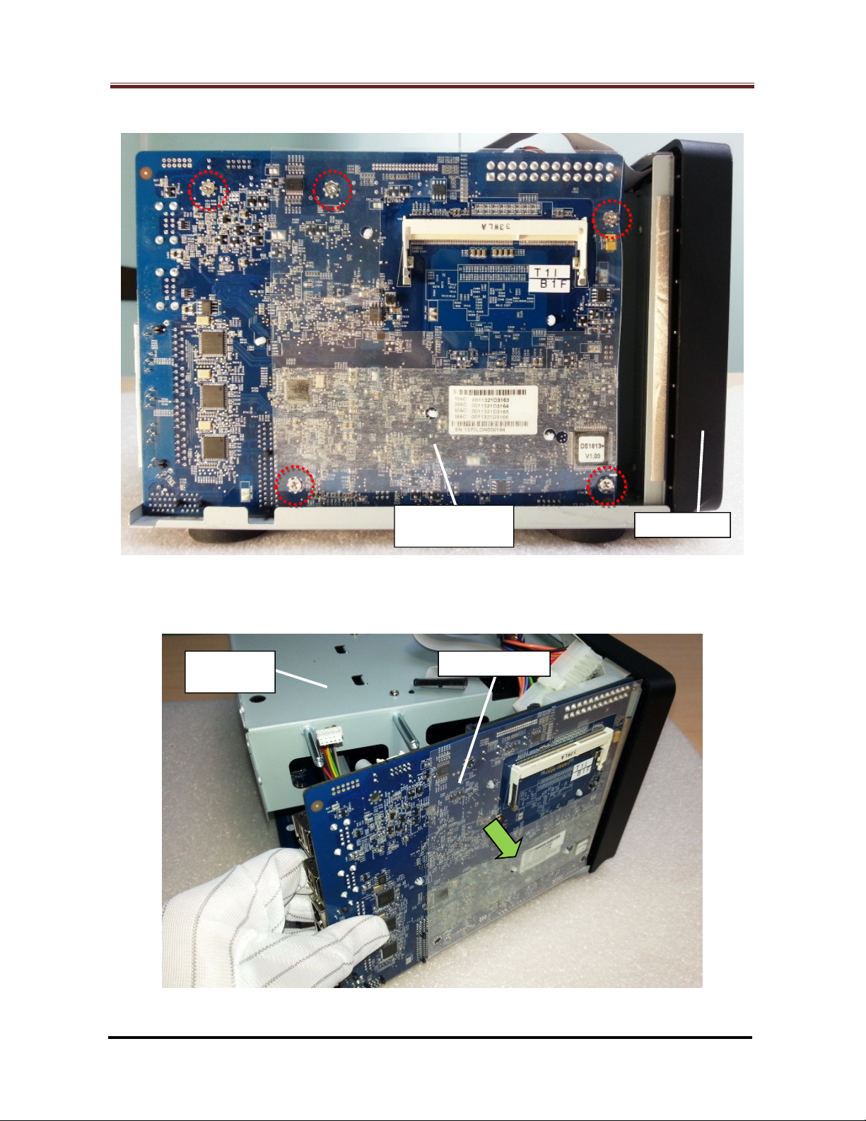
2.1.10 Release the five (5) screws (Marked by the red circles). (Fig. 11)
Fig. 11
2.1.11 Then remove the motherboard from the chassis. (Fig. 12)
Fig. 12
Date: 2014/4/11
Issued by: Hardware Development Group, Synology ® Inc.
Page 10 of 39
Page 11
How to Replace Hard Disk Backplane for 8 bay/5 bay DiskStation
F
ront Panel
Enclosure
- Top
24-pin PSU Cable
Connector
LED Cable
Connector
Front Panel
Enclosure
- Top
24-pin PSU Cable
Connector
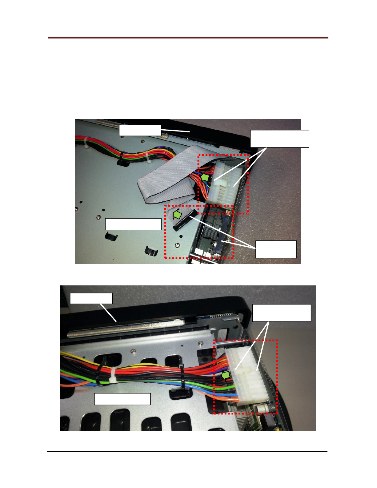
2.1.12 Unplug the 24-pin PSU cable connector and LED cable connector (Marked by the
red rectangles) from the motherboard. (Fig. 13 for DS1813+, DS1513+, DX513 (*),
Fig. 14 and 15 for DS1812+, DS1512+, DS1511+, DX513 (*), DX510)
Note: For DX513, proceed this step as shown in Fig. 13 or Fig. 14/15 by the
location of its LED cable connector.
Fig. 13 - For DS1813+, DS1513+, DX513
Fig. 14 - For DS1812+, DS1512+, DS1511+, DX513, DX510
Page 11 of 39
Date: 2014/4/11
Issued by: Hardware Development Group, Synology ® Inc.
Page 12
How to Replace Hard Disk Backplane for 8 bay/5 bay DiskStation
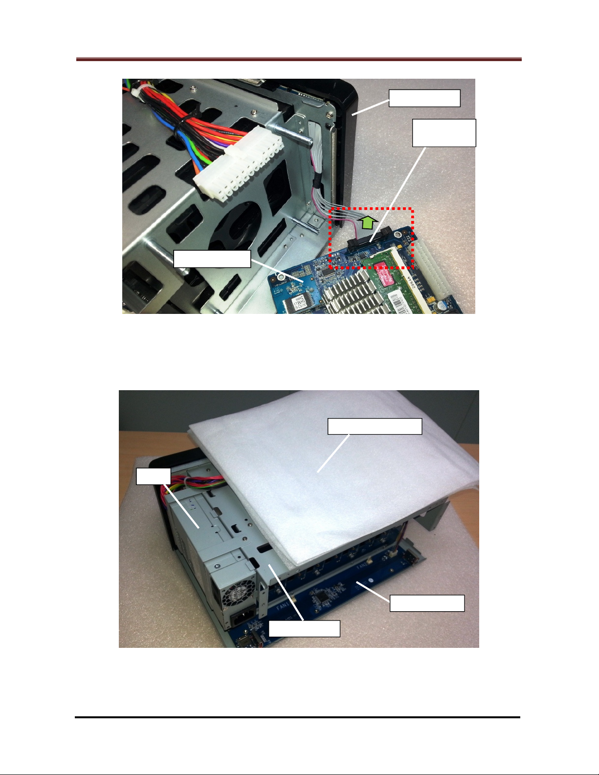
LED Cable
Connector
Motherboard
Front Panel
eSATA Board
HDD Chassis
PSU
Fig. 15 - For DS1812+, DS1512+, DS1511+, DX513, DX510
2.1.13 Place some cushion material (For example, EPE sheets) on top of the HDD
chassis. (Fig. 16)
Fig. 16
Page 12 of 39
Date: 2014/4/11
Issued by: Hardware Development Group, Synology ® Inc.
Page 13

How to Replace Hard Disk Backplane for 8 bay/5 bay DiskStation
PSU
PSU Bracket
Front
Panel
PSU
PSU Bracket
Front Panel
2.1.14 Release the two (2) screws (Marked by the red circles) which fix the PSU. (Fig. 17
for DS1813+ and DS1812+, Fig. 18 for DS1513+, DS1512+, DS1511+, DX513 and
DX510).
Fig. 17 – For DS1813+, DS1812+
Fig. 18 – For DS1513+, DS1512+, DS1511+, DX513 and DX510
Date: 2014/4/11
Issued by: Hardware Development Group, Synology ® Inc.
Page 13 of 39
Page 14

How to Replace Hard Disk Backplane for 8 bay/5 bay DiskStation
PSU
PSU Bracket
Front Panel
PSU
PSU Bracket
Front Panel
2.1.15 Release the two (2) screws (Marked by the red circles) which fix the PSU. (Fig. 19
for DS1813+ and DS1812+, Fig. 20 for DS1513+, DS1512+, DS1511+, DX513 and
DX510). Then remove the PSU bracket(s).
Fig. 19 – For DS1813+, DS1812+
Fig. 20 – For DS1513+, DS1512+, DS1511+, DX513 and DX510
Date: 2014/4/11
Issued by: Hardware Development Group, Synology ® Inc.
Page 14 of 39
Page 15

How to Replace Hard Disk Backplane for 8 bay/5 bay DiskStation
PSU
PSU
Front Panel
12-pin PSU Cable
Connector
8-pin PSU Cable
Connector
2.1.16 Remove the PSU from the enclosure then flip it up with its top side lain on the
cushion. (Fig. 21)
Fig. 21
2.1.17 Unplug the 12-pin and 8-pin PSU cable connectors (Marked by the red rectangle).
(Fig. 22)
Fig. 22
Page 15 of 39
Date: 2014/4/11
Issued by: Hardware Development Group, Synology ® Inc.
Page 16

How to Replace Hard Disk Backplane for 8 bay/5 bay DiskStation
eSATA Bo
ard
HDD Chassis
eSATA Board
HDD Chassis
Defective HDD
Defective HDD
8-pin PSU Cable
Connector
2.1.18 For DS1813+, DS1812+:
Release the three (3) screws (Marked by the red circles) which fix the eSATA
board. (Fig. 23 and Fig. 24) Then remove the eSATA board.
Backplane
Fig. 23
Backplane
Fig. 24
Date: 2014/4/11
Issued by: Hardware Development Group, Synology ® Inc.
Page 16 of 39
Page 17

How to Replace Hard Disk Backplane for 8 bay/5 bay DiskStation
HDD Chassis
Defective HDD Backplane
– Back Side
HDD Chassis
Defective HDD Backplane
– Back Side
Release the four (4) screws (Marked by the red circles) which fix the defective
HDD backplane assembly. (Fig. 25)
Fig. 25
Remove the defective HDD backplane assembly. (Fig. 26)
Date: 2014/4/11
Issued by: Hardware Development Group, Synology ® Inc.
Fig. 26
Page 17 of 39
Page 18

How to Replace Hard Disk Backplane for 8 bay/5 bay DiskStation
Metal Frame Set
Upper Metal Frame Set
Defective HDD Backplane
– SATA Connector Si
de
Defective HDD Backplane
– SATA Connector Side
PSU Cable
Connector
Release the screw on top of the upper metal frame (Marked by the red
circles). (Fig. 27)
Fig. 27
Release the four (4) screws (Marked by the red circles) to remove the
defective HDD backplane from the two sets of metal frame. (Fig. 28)
Date: 2014/4/11
Issued by: Hardware Development Group, Synology ® Inc.
Fig. 28
Page 18 of 39
Page 19

How to Replace Hard Disk Backplane for 8 bay/5 bay DiskStation
Upper Metal Frame
Defective HDD Backplane
– SATA Connector Side
Lower Metal Frame
HDD Chassis
Defective HDD
PSU Cable
Fig. 29 shows the status after the defective HDD backplane is removed from the
two metal frame sets.
Fig. 29
2.1.19 For DS1513+, DS1512+, DS1511+, DX513 and DX510:
Release the five (5) screws (Marked by the red circles) which fix the defective
HDD backplane. (Fig. 30 and Fig. 31)
Backplane
Date: 2014/4/11
Issued by: Hardware Development Group, Synology ® Inc.
Fig. 30
Page 19 of 39
Page 20

How to Replace Hard Disk Backplane for 8 bay/5 bay DiskStation
Front Panel
HDD Chassis
Defective HDD
HDD Chassis
Defective HDD Backplane
Backplane
Fig. 31
Bring the defective HDD backplane through the opening on the HDD chassis
to remove it. (Fig. 32) Do not damage the aluminum foil pasted on the HDD
chassis when moving the backplane.
Date: 2014/4/11
Issued by: Hardware Development Group, Synology ® Inc.
Fig. 32
Page 20 of 39
Page 21

How to Replace Hard Disk Backplane for 8 bay/5 bay DiskStation
HDD Chassis
Defective HDD Backplane
– SATA Connector Side
Fig. 33 shows the status after the defective HDD backplane is removed from the
HDD chassis.
Fig. 33
Date: 2014/4/11
Issued by: Hardware Development Group, Synology ® Inc.
Page 21 of 39
Page 22

How to Replace Hard Disk Backplane for 8 bay/5 bay DiskStation
Replacement HDD Backplane
– SATA Connector Side
Uppe
r Metal Frame
(Up Side Down)
Replacement HDD Backplane
(Up Side Down)
2.2 Install the replacement HDD backplane
2.2.1 For DS1813+, DS1812+:
Insert the bottom edge of the replacement HDD backplane to the space
between the two lower metal frames. Then fix the two (2) screws (Marked by
the red circles) to secure them together. (Fig. 34)
Fig. 34
Assemble the replacement HDD backplane (Top edge) and the two upper metal
frames. Then fix the two (2) screws (Marked by the red circles) to secure them
together. (Fig. 35)
– SATA Connector Side
Date: 2014/4/11
Issued by: Hardware Development Group, Synology ® Inc.
Fig. 35
Page 22 of 39
Page 23

How to Replace Hard Disk Backplane for 8 bay/5 bay DiskStation
Upper Metal Frame Set
Replacement
HDD Backplane
– SATA Connector Side
PSU Cable
Connector
HDD Chassis
Replacement HDD Backplane
– Back Side
Fix the screw on top of the upper metal frame (Marked by the red circles). (Fig.
36)
Fig. 36
Insert the replacement HDD backplane assembly to the same location of the
defective one in the enclosure. (Fig. 37)
Date: 2014/4/11
Issued by: Hardware Development Group, Synology ® Inc.
Fig. 37
Page 23 of 39
Page 24

How to Replace Hard Disk Backplane for 8 bay/5 bay DiskStation
HDD Chassis
Replacement HDD Backplane
– Back Side
eSATA Board
HD
D Chassis
Replacement
Fix the four (4) screws (Marked by the red circles). (Fig. 38)
Fig. 38
Restore the eSATA board to its original location in the enclosure. Then fix the
three (3) screws (Marked by the red circles) to secure it. (Fig. 39 and Fig. 40)
HDD Backplane
Date: 2014/4/11
Issued by: Hardware Development Group, Synology ® Inc.
Fig. 39
Page 24 of 39
Page 25

How to Replace Hard Disk Backplane for 8 bay/5 bay DiskStation
eSATA Board
HDD Chassis
Replacement
8-pin PSU Cable
Connector
HDD Chassis
Replacement
HDD Backplane
HDD Backplane
Fig. 40
2.2.2 For DS1513+, DS1512+, DS1511+, DX513 and DX510:
Insert the replacement HDD backplane to the same location of the defective
one in the enclosure. (Fig. 41) Do not damage the aluminum foil pasted on the
HDD chassis when moving the backplane.
Fig. 41
Date: 2014/4/11
Issued by: Hardware Development Group, Synology ® Inc.
Page 25 of 39
Page 26

How to Replace Hard Disk Backplane for 8 bay/5 bay DiskStation
HDD Chassis
Replacement
PSU Cable
Front Panel
HDD Chassis
Replacement
Fix the five (5) screws (Marked by the red circles) to secure the replacement
HDD backplane. (Fig. 42 and Fig. 43)
HDD Backplane
Fig. 42
HDD Backplane
Fig. 43
Page 26 of 39
Date: 2014/4/11
Issued by: Hardware Development Group, Synology ® Inc.
Page 27

How to Replace Hard Disk Backplane for 8 bay/5 bay DiskStation
PSU
Front Panel
12-pin PSU Cable
Connector
8-pin PSU Cable
Connector
PSU
2.2.3 Plug back the 12-pin and 8-pin PSU cable connectors (Marked by the red rectangle)
to their original locations on the HDD backplane. (Fig. 44)
Fig. 44
2.2.4 Restore the PSU to its original location in the enclosure. (Fig. 45)
Fig. 45
Page 27 of 39
Date: 2014/4/11
Issued by: Hardware Development Group, Synology ® Inc.
Page 28

How to Replace Hard Disk Backplane for 8 bay/5 bay DiskStation
PSU
PSU Bracket
Front Panel
PSU
PSU Bracket
Front Panel
2.2.5 Restore the PSU bracket(s) to the original location(s). Then fix the two (2) screws
(Marked by the red circles) to secure the bracket(s)/PSU. (Fig. 46 for DS1813+ and
DS1812+, Fig. 47 for DS1513+, DS1512+, DS1511+, DX513 and DX510)
Fig. 46 – For DS1813+, DS1812+
Fig. 47 – For DS1513+, DS1512+, DS1511+, DX513 and DX510
Page 28 of 39
Date: 2014/4/11
Issued by: Hardware Development Group, Synology ® Inc.
Page 29

How to Replace Hard Disk Backplane for 8 bay/5 bay DiskStation
PSU
PSU Bracket
Front Panel
PSU
PSU Bracket
Front Panel
2.2.6 Fix the two (2) screws (Marked by the red circles) to secure the bracket(s)/PSU.
(Fig. 48 for DS1813+ and DS1812+, Fig. 49 for DS1513+, DS1512+, DS1511+,
DX513 and DX510) Then remove the cushion.
Fig. 48 – For DS1813+, DS1812+
Fig. 49 – For DS1513+, DS1512+, DS1511+, DX513 and DX510
Page 29 of 39
Date: 2014/4/11
Issued by: Hardware Development Group, Synology ® Inc.
Page 30

How to Replace Hard Disk Backplane for 8 bay/5 bay DiskStation
Front Panel
Enclosure
- Top
24-pin PSU Cable
Connector
LED Cable
Connector
Front Panel
LED Cable
Connector
Motherboard
2.2.7 Plug back the 24-pin PSU cable connector and LED cable connector (Marked by
the red rectangles) to their original locations on the motherboard. (Fig. 50 for
DS1813+, DS1513+, DX513 (*), Fig. 51 and Fig. 52 for DS1812+, DS1512+,
DS1511+, DX513 (*), DX510)
Note: For DX513, proceed this step as shown in Fig. 50 or Fig. 51/52 by the
location of its LED cable connector.
Fig. 50 - For DS1813+, DS1513+, DX513
Fig. 51 - For DS1812+, DS1512+, DS1511+, DX513, DX510
Page 30 of 39
Date: 2014/4/11
Issued by: Hardware Development Group, Synology ® Inc.
Page 31

How to Replace Hard Disk Backplane for 8 bay/5 bay DiskStation
#3
RAM
Module
Front Panel
Enclosure
- Top
24-pin PSU Cable
Connector
Fig. 52 - For DS1812+, DS1512+, DS1511+, DX513, DX510
2.2.8 To restore the motherboard into the enclosure, there are two (2) locations as follow
for joining the two sides:
Motherboard Side (Fig. 53) Enclosure Side (Fig. 54)
#1 PCI Express connector (Large) #2 Bonding finger of the HDD backplane
#3 PCI Express connector (Small) #4 Bonding finger of the eSATA board
Fig. 53 – Motherboard Side
Page 31 of 39
Date: 2014/4/11
Issued by: Hardware Development Group, Synology ® Inc.
Page 32

How to Replace Hard Disk Backplane for 8 bay/5 bay DiskStation
#2
HDD
Backplane
eSATA
Board
Enclosure
- Top
Motherboard
Fig. 54 – Enclosure Side
Restore the motherboard to its original location in the chassis. (Fig. 55)
Fig. 55
Page 32 of 39
Date: 2014/4/11
Issued by: Hardware Development Group, Synology ® Inc.
Page 33

How to Replace Hard Disk Backplane for 8 bay/5 bay DiskStation
#2
Motherboard
eSATA
Board
H
DD
Front Panel
Isolating Mylar
(Transparent)
#4
2.2.9 Join the motherboard and the enclosure together with the followings (Fig. 56):
The bonding finger of the HDD backplane (#2) inserted into the PCI Express
connector (Large) (#1) properly.
The bonding finger of the eSATA board (#4) inserted into the PCI Express
connector (Small) (#3) properly.
Backplane
Fig. 56
2.2.10 Fix the five (5) screws (Marked by the red circles) to secure the motherboard. (Fig.
57)
Fig. 57
Date: 2014/4/11
Issued by: Hardware Development Group, Synology ® Inc.
Page 33 of 39
Page 34

How to Replace Hard Disk Backplane for 8 bay/5 bay DiskStation
Enclosure
- Top
Motherboard
eSATA Board
Cable Connector
Rear Panel
Enclosure
- Top
Motherboard
eSATA Board
Cable Connector
2.2.11 Plug back the eSATA board cable connector(s) (Marked by the red rectangle) to
the original location(s) on the motherboard. (Fig. 58 for DS1813+, DS1513+,
DX513 and Fig. 59 for DS1812+, DS1512+, DS1511+, DX513 and DX510):
Fig. 58 – For DS1813+, DS1513+, DX513
Fig. 59 – For DS1812+ (*), DS1512+ (*), DS1511+, DX513, DX510
Note: Fig. 60 and Fig. 61 show how the eSATA board cables are connected with the
eSATA board. (Fig. 60 for DS1812+, Fig. 61 for DS1512+) Follow the way when
plugging back the eSATA board cable connectors.
Page 34 of 39
Date: 2014/4/11
Issued by: Hardware Development Group, Synology ® Inc.
Page 35

How to Replace Hard Disk Backplane for 8 bay/5 bay DiskStation
Connector CN1
Connector CN8
Connector CN2
Connector CN6
Connector CN1
Connector CN
7
Connector CN2
Connector CN
5
Fig. 60 – For DS1812+
Fig. 61 – For DS1512+
Page 35 of 39
Date: 2014/4/11
Issued by: Hardware Development Group, Synology ® Inc.
Page 36

How to Replace Hard Disk Backplane for 8 bay/5 bay DiskStation
Enclosure
- Bottom
Rear Panel
Front
Panel
Disk Tray
2.2.12 For DS1813+, DS1812+:
Fix the screw on the enclosure bottom (Marked by the red circles) to secure the
replacement HDD backplane assembly. (Fig. 62)
Fig. 62
2.2.13 Restore all the disk trays into the HDD chassis. (Fig. 63)
Fig. 63
Date: 2014/4/11
Issued by: Hardware Development Group, Synology ® Inc.
Page 36 of 39
Page 37

How to Replace Hard Disk Backplane for 8 bay/5 bay DiskStation
Fan Cable
Connector #1
Fan Cable
Connector #2
eSATA Board
Rear Panel
2.2.14 Plug back the two (2) fan cable connectors (Marked by the red rectangles) to their
original locations on the eSATA board. (Fig. 64)
Fig. 64
2.2.15 Restore the fan panel to the enclosure. (Fig. 65)
Fig. 65
Page 37 of 39
Date: 2014/4/11
Issued by: Hardware Development Group, Synology ® Inc.
Page 38

How to Replace Hard Disk Backplane for 8 bay/5 bay DiskStation
Enclosure
- Bottom
Rear Panel
Fan Pan
el
Rear Panel
Fan #1
Fan #2
2.2.16 Fix the four (4) screws on the rear panel (Marked by the red circles). (Fig. 66)
Fig. 66
2.2.17 Fix the three (3) screws on enclosure bottom (Marked by the red circles) to secure
the rear panel. (Fig. 67)
Fig. 67
Page 38 of 39
Date: 2014/4/11
Issued by: Hardware Development Group, Synology ® Inc.
Page 39

How to Replace Hard Disk Backplane for 8 bay/5 bay DiskStation
Fan Panel
Rear Panel
Fan #1
Fan #2
Fan Panel
Enclosure
2.2.18 Restore the enclosure cover to its original location. (Fig. 68)
Cover - Top
Fig. 68
2.2.19 Fix the six (6) screws on the rear panel (Marked by the red circles) to secure the
enclosure cover. (Fig. 69)
Fig. 69
2.3 The replacing task is completed.
Page 39 of 39
Date: 2014/4/11
Issued by: Hardware Development Group, Synology ® Inc.
 Loading...