

Page 1
Canterbury™
Widespread Lavatory Faucet SLW-4512
Installation and Service Instructions
Model Numbers
SLW-4512
Lavatory faucet with
pop-up drain
Tools & Materials
Need Help?
Contact Symmons customer service at
P: (800) 796-6667, F: (800) 961-9621
Email: customerservice@symmons.com
Monday - Friday 7:30 am - 7:00 pm EST
Alternate Finish Code
append to part numbers when applicable
-STN
--
Satin Nickel
Chrome (standard)
Pipe
Sealant
Plumbers
Putty
Please check Symmons website
for technical help, the latest product
information and warranty policy.
www.symmons.com/service
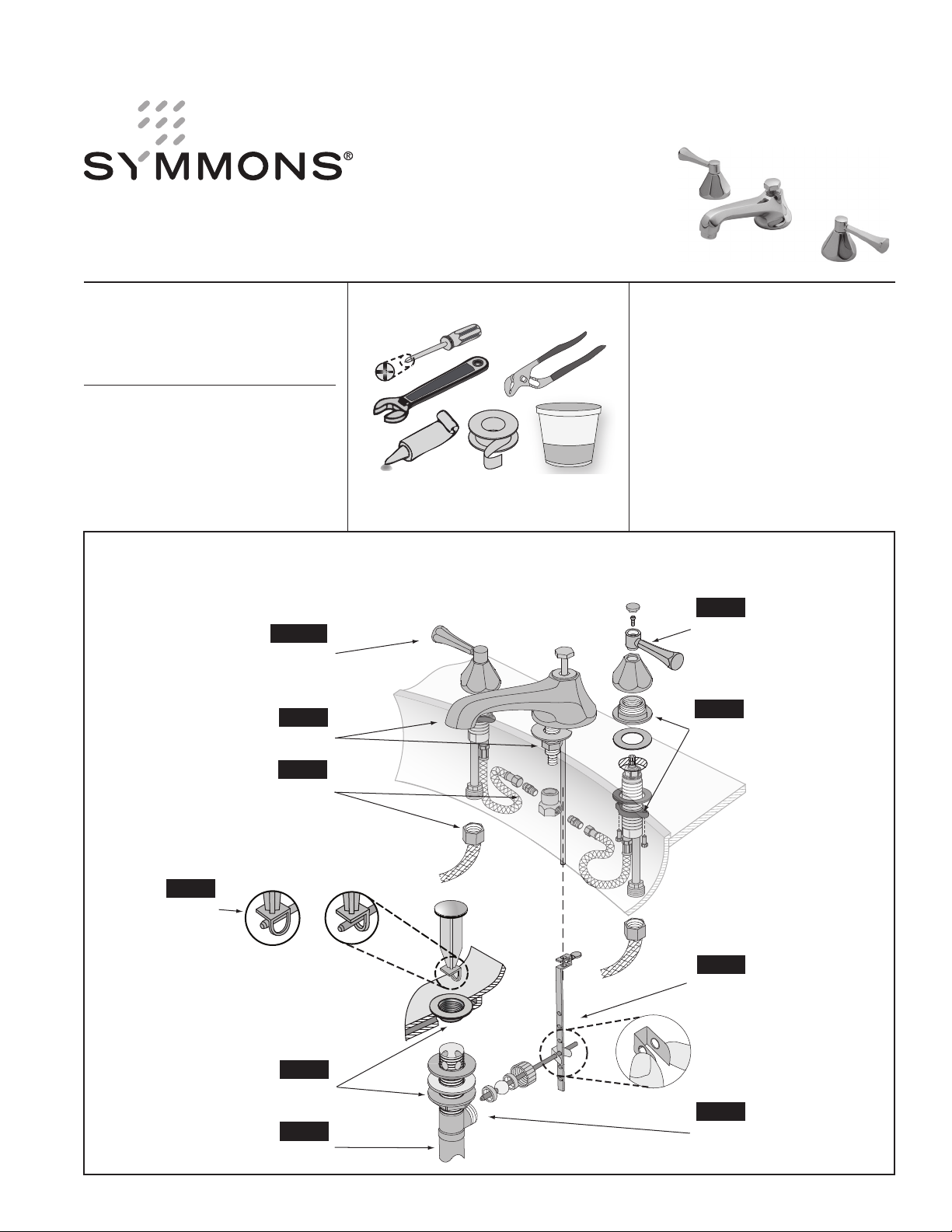
Quick Install Guide Canterbury Widespread Lavatory Faucet, SLW-4512
Step 2
Step 10
Flush water supply lines
Step 3
Step 1
Attach faucet spout
Attach faucet handles
Step 1
Attach control valves to sink
SConnect water supply lines
NonRemovable Removable
stopper stopper
Step 6
Install stopper and
set eye position
Fasten drain body and
tail piece to sink
Attach drain body to drain trap
Step 4
Step 5
Step 9
Step 8
Connect lift rod, clevis strap,
pivot rod and adjust linkage
Step 7
Attach pivot rod to drain body
Page 2
PLUMBERS
PUTTY
Installation Instructions
Installation Instructions
Caution: If replacing an older faucet ensure water supply
is turned OFF before removing. en open faucet valves to
relieve water pressure.
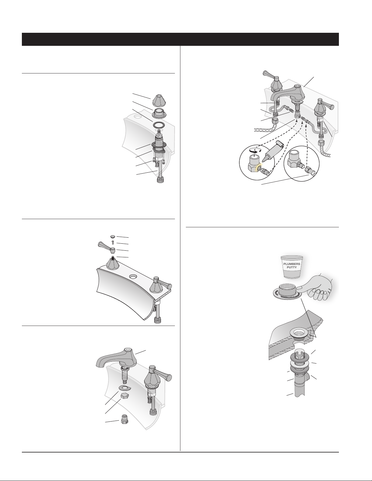
Step 1 Attach control valves to sink
■ read ange nut down 2
inches from threaded end
of valve body.
■ Insert valve body from
underneath sink through
mounting hole. Ensure
valve with red label (hot)
is on le and blue label
(cold) is on right.
mounting washer
■ Place gasket over valve
body and thread fastener
mounting screws
onto valve body until stop
is reached.
■ Tighten ange nut and mounting washer under sink and
secure with mounting screws if necessary.
■ read collar over outer threads of
fastener until tightened against surface of the sink.
collar
fastener
gasket
ange nut
valve body
Step 2 Attach faucet handles
■ Turn valve spindles to
the OFF position.
HOT - le valve,
clockwise
COLD - right valve,
counter clockwise
■ Attach handle to valve
spindle in OFF location
as shown.
■ Fasten to spindle with
Phillips head screw
and insert plug button.
plug button
screw
handle
valve spindle
Step 3 Attach faucet spout to sink
■ Unscrew tee and
remove washer
and nut from
threaded end of
spout as shipped.
■ Insert end of spout
down through
mounting hole in
sink and then fasten
from under sink
with washer and nut.
■ Tighten nut while
washer
nut
tee
ensuring spout is
centered over mounting hole and
at edge of washer is facing rear of sink.
spout
Step 4 Connect water supply lines
■ Apply pipe sealant on both ex hose adapters and thread
into sides of tee.
spout
■ read center of
tee onto end of
spout.
Note: is may
require about
4 inches of
clearance to
valve
outlet
& inlet
ex hose
adapter
rotate.
■ Attach ex hoses
to ex hose
adapters.
tee
Pipe
Sealant
■ Plumb hot water
supply to le
valve inlet, cold
water to right
ex hose
inlet (supply
hoses not included).
■ Check for leaks if only replacing faucet and drain is already
installed by rst turning faucet handles to the OFF position
and then turn water supply valves ON.
Step 5 Fasten drain body to sink
■ Remove stopper, unscrew ange and remove at rubber
washer from end of drain
body as shipped.
■ Apply plumber’s putty
around bottom of ange.
■ Move friction washer,
beveled washer and
ange nut down away
from threaded end
of drain body.
■ Place ange in drain
opening and under sink
screw drain body up into
ange at least 2-3 turns
until hand tight. Apply
putty or teon tape to tail
piece and attach to drain
body.
■ Position drain body so
ange nut
drain body
pivot cavity is facing
rear of sink and then
slide beveled washer and
tail piece
friction washer up against sink.
■ Tighten ange nut up against friction washer to evenly
compress beveled washer while also ensuring ange
is centered in drain opening.
Take care not to over tighten ange nut.
ange
beveled
washer
friction
washer
pivot
cavity
valve
body
Page 2
Page 2
Page 3

Step 6 Install stopper and set eye position
stopper
Stopper can be removable
or non-removable
determined by position
of eye hole when
inserting pivot rod.
non
removable removable
ange
■ Insert stopper
through ange
opening and
position eye hole.
Removing stopper When installed in removable position,
move pivot rod to the up position (li rod is in the down position
when later installed). Eye hole will slide over end of pivot rod.
Step 7 Attach pivot rod to drain body
■ Remove retaining nut
and outer seat from
pivot cavity.
■ Insert pivot rod
into pivot cavity so
ball is against inner
seat and end of rod
passes under stopper
according to selected
eye hole position.
pivot rod
retaining nut
outer seat
pivot ball
inner seat
pivot cavity
■ Slide outer seat over
pivot rod with curved end against pivot ball.
■ Fasten pivot rod to drain body with retaining nut.
Tighten using your ngers until ball is seated snug
and pivot rod can move around freely.
Step 8 Connect lift rod and adjust linkage
■ Insert li rod through
hole on top of water
spout.
■ Fasten end of pivot
rod with spring clip
through location
hole in clevis strap
that is best aligned
to enable li rod also
clevis strap
fasten to end of clevis
strap when in the up
position and stopper
is in the closed
position.
■ Insert li rod into
end of clevis strap
and fasten with
pivot rod
thumb screw at
location where stopper can be easily opened and closed.
If necessary, select another location hole in clevis
strap and re-adjust li rod where fastened to clevis strap.
lift rod
thumb
screw
location
holes
spring
clip
Step 9 Attach drain body to drain trap
Step 10 Flush water supply lines
oroughly ush supply
lines to prevent foreign
matter, i.e. copper chips,
sand, etc. from damaging
remove
aerator
the sealing surface inside
control valves.
■ Remove aerator from
end of faucet spout
by rotating counter
clockwise
■ Turn hot and cold faucet
handles to full ON position and then open
water supply valves to ush supply lines thoroughly.
■ Turn faucet OFF, replace aerator and check for any leaks.
Care of faucet finish
Clean nish area by using mild soap and water or non-abrasive
cleaner and then rinse immediately. A non-abrasive wax may
be used to preserve nish area.
Valve cartridge replacement
Step 1 Remove handle
Carefully pry loose button plug and remove Phillips head screw.
Step 2 Remove collar
Remove collar by turning counter
clockwise.
Note: Ensure not to use any tool
that could scratch nish without
taking protective measures.
Step 3 Remove cartridge
Using a wrench, turn hex nut
on cartridge counter clockwise.
Note: Ensure valve assembly under
sink doesn’t rotate
while turning nut.
Step 4 Insert cartridge
Insert replacement cartridge and
tighten hex nut using a wrench.
Step 5 Attach collar
Screw collar onto fastener and
tighten using your hand.
Step 6 Attach faucet handle
■ Ensure cartridge spindle is
rotated to the OFF position.
■ Attach handle to top of spindle
in OFF location as shown.
■ Fasten with screw and replace
button plug.
Page 3Page 3
plug button
screw
handle
collar
spindle
OFF
hot = cw
cold = ccw
cartridge
fastener
handles set in
the OFF position
Page 4

*
append appropriate three letter sufx code to part
numbers marked with an asterisk (
*
Dimensions Canterbury Widespread Lavatory Faucet, SLW-4512
8" (203 mm) min
16" (406 mm) max
4" (102 mm) min
3-1/8" (80 mm)
Deck thickness
1-3/8" (35 mm) max
1" dia. (25 mm)
Hole size
1-1/16" (27 mm) min
1-7/16" (37 mm) max
Flexible hose
Note: Dimensions subject to change without notice.
2" dia
(51 mm)
2-7/8"
73 mm
1-7/16" (36 mm)
13/16" dia. (21 mm)
1-1/8" (29 mm) min
1-1/2" (38 mm) max
5-15/16"
(151 mm)
Hole size
~
Parts Assembly Canterbury Widespread Lavatory Faucet, SLW-4512
2-3/8" dia
(60 mm)
5/8"
(16 mm)
standard aerator
2.2 gpm
faucet handle
reference table
valve cartridge
reference table
stopper
P-100N*
pop-up drain
assembly
RL-154LR
includes stopper
lift rod
LN-271
*
Part Number Item
WSF-LOC-RB-KIT
1 handle plus both
red and blue
indicator rings
included.
WSF-LOC-RP-KIT
1 handle included,
handle does not
include indicator
rings.
KN-114 (hot)
OFF = CW
KN-113 (cold)
OFF = CCW
LN-15
*
FLR-110-1.5
FLR-110-1.0
Note: For faucets with an optional decorative nish,
*
Ordering replacement parts:
Contact Symmons customer service at P: (800) 796-6667,
F: (800) 848-2250 M-F 7:30 am - 7:00h pm EST or
check our website at www.symmons.com for a
list of Symmons distributors.
Replacement Parts
(1)
indicator ring
hot=red, cold=blue
*
plug button
screw
handle
collar
*
(1) Indicator ring is included
on some model faucets.
KN-113
identified
by groove
aerator ow rates
2.2 gpm (8.3L/min)
*
*
1.5 gpm (5.7L/min)
1.0 gpm (3.8L/min)
fastener
gasket
valve cartridge
).
aerator
Symmons Industries, Inc. ■ 31 Brooks Drive ■ Braintree, MA 02184
Phone: (800) 796-6667 ■ Fax: (800) 961-9621
Website:
© 2014 Symmons Industries, Inc. Printed in U.S.A. ■ ZV-566 ■ Rev B ■ 101014
www.symmons.com
■ Email:
gethelp@symmons.com
 Loading...