

Page 1

59552A
Fiber-Optic Distribution
Amplifier
097-59552-01
Issue 1: Apr 00
and
59553A
Fiber-Optic Receiver
User’s Guide
Copyright © 2000 Symmetricom, Inc. All rights reserved. Printed in U.S.A.
Page 2

This manual describes a Symmetricom fiber-optic
distribution amplifier and a Symmetricom fiberoptic receiver, including their system hardware and
software.
Warning Symbols That May Be Used In This Book
This operating manual is the primary document for
the 59552A Fiber-Optic Distribution Amplifier and
the 59553A Fiber-Optic Receiver.
This manual applies to the 59552A Fiber-Optic
Distribution Amplifier and 59553A Fiber-Optic
Receiver you have received unless update
information is included with the equipment.
For assistance, contact:
Symmetricom, Inc.
2300 Orchard Parkway
San Jose, CA 95131-1017
U.S.A. Call Center:
888-367-7966 (from inside U.S.A. only – toll
free)
408-428-7907
U.K. Call Center:
+44.7000.111666 (Technical Assistance)
+44.7000.111888 (Sales)
Instruction manual symbol; the product will be marked with this
symbol when it is necessary for the user to refer to the
instruction manual.
Indicates hazardous voltages.
Indicates earth (ground) terminal.
or
Indicates terminal is connected to chassis when such connection
is not apparent.
Indicates Alternating current.
Fax: 408-428-7998
E-mail: ctac@symmetricom.com
Internet: http://www.symmetricom.com
Indicates Direct current.
Page 3

Contents
In This Guide
Guide Organization v
Description of Symmetricom Fiber-Optic Distribution
Amplifier and Receiver vi
59552A Fiber-Optic Distribution Amplifier vi
59553A Fiber-Optic Receiver vii
1Getting Started
Typical Timing Signal Distribution System 1-2
59552A Front Panel at a Glance 1-3
59552A Rear Panel at a Glance 1-4
59553A Front Panel at a Glance 1-5
59553A Rear Panel at a Glance 1-6
Preparing the 59552A/59553A for Use 1-7
To Connect AC Power 1-7
To Assemble and Connect the +129 Vdc IEC 320 Connector/
Cable 1-8
2 Configuring Your 59552A/59553A
Chapter Contents 2-2
Introduction 2-3
Removing the Covers 2-5
Tools Required 2-5
To Remove 59552A Cover 2-5
To Remove 59553A Cover 2-6
Configuring for One-Signal Distribution
(Digital Mode Operation) 2-9
Overview of the Digital Mode 2-9
To Configure the 59552A and 59553A for Digital Mode
Operation 2-11
Configuring the 59552A for Digital Mode 2-11
Configuring the 59553A for Digital Mode 2-13
Configuring for Two-Signal Distribution
(Combined Mode Operation) 2-16
Overview of Combined Mode 2-16
To Configure the 59552A and 59553A for Combined Mode
Operation 2-18
Configuring the 59552A for Combined Mode
Operation 2-18
User’s Guide iii
Page 4

Contents
Configuring the 59553A for Combined Mode
Operation 2-20
3 Operational Verification
Chapter Contents 3-2
Introduction 3-3
Equipment Required 3-3
59552A/59553A Operational Verification 3-4
Setup 3-4
Digital Out (1 PPS) and Analog (IRIG) Out Waveform
Tests 3-5
LED Indicator Test 3-6
4 Specifications
Introduction 4-2
Index
iv User’s Guide
Page 5

In This Guide
This preface contains the following information:
• Guide Organization page v
• Description of Symmetricom Fiber-Optic Distribution
Amplifier and Receiver
page vi
Guide Organization
Table of Contents lists the beginning of each chapter in the guide,
helping you locate information.
In This Guide (this preface) introduces you to the User’s guide,
provides product descriptions, and general information on the
59552A Fiber-Optic Distribution Amplifier and the 59553A Fiber-Optic
Receiver.
Chapter 1, “Getting Started,” introduces you to the 59552A/59553A
with illustrated overviews of a typical distribution system, and the
59552A/59553A’s front and rear panels. A section on power cabling
requirements is also provided.
Chapter 2, “Configuring Your 59552A/59553A,” provides
configuration procedures with overview information for the
59552A/59553A.
Chapter 3, “Operational Verification,” provides an abbreviated
series of checks that may be performed to give an high degree of
confidence that the 59552A and 59553A are operating properly.
Chapter 4, “Specifications,” lists the 59552A and 59553A
specifications and characteristics.
Index
User’s Guide v
Page 6

In This Guide
Description of Symmetricom Fiber-Optic
Distribution Amplifier and Receiver
High-integrity distribution of a common clock is the backbone for
power-utility substation synchronization. The 59552A Fiber-Optic
Distribution Amplifier and the 59553A Fiber-Optic Receiver provide a
simple, modular approach to signal routing. Immunity to electrical
noise makes fiber-optic cable a superior choice for the challenging
environment of the power substation.
59552A Fiber-Optic Distribution Amplifier
The 59552A Fiber-Optic Distribution Amplifier, used with the 59553A
Fiber-Optic Receivers, provides clean, timing-quality transmission of
precise frequency and time signals, or distribution of timing signals for
various applications (such as the analysis, monitoring, and control of
power-utility substations). In a typical application requiring
distribution of one pulse per second (1 PPS) and IRIG-B time code, the
59552A provides an identical, synchronous clock signal and precise
time of day to every distribution point.
The 59552A Fiber-Optic Distribution Amplifier receives a digital (TTL)
signal and an analog signal via two BNC connectors. The distribution
amplifier combines the signals, and transmits the result on each of the
eight fiber-optic outputs. Signal integrity is maintained over fiber-optic
cable lengths of up to 1 kilometer (3,281 feet). One 59553A receiver is
required for each of the outputs that are used.
The 59552A front-panel LEDs provide quick status indication.
The 59552A is completely compatible with the 59551A GPS
Measurements Synchronization Module, which provides high-quality
timing signals (both 1 PPS and IRIG-B) as standard rear-panel
outputs.
vi User’s Guide
Page 7

In This Guide
59553A Fiber-Optic Receiver
The 59553A Fiber-Optic Receiver is located at remote equipment
installations to receive a distributed signal from a common clock.
The 59553A receives the signal on fiber-optic cable, separates the
analog and digital waveforms, reconstructs the analog time code,
and outputs each signal to a BNC connector.
The 59553A, used with the 59552A Fiber-Optic Distribution Amplifier,
provides clean, timing-quality transmission to analyze monitoring and
control equipment in power-utility substations, or any application
involving precise frequency and time signals. In a typical application
requiring distribution of one pulse per second (1 PPS) and IRIG-B time
code, the 59953A ensures an identical, synchronous clock signal and
precise time of day at each distribution point.
The 59553A front-panel LEDs provide quick status indication.
User’s Guide vii
Page 8

In This Guide
viii User’s Guide
Page 9

1
Getting Started
Page 10

Chapter 1 Getting Started
Typical Timing Signal Distribution System
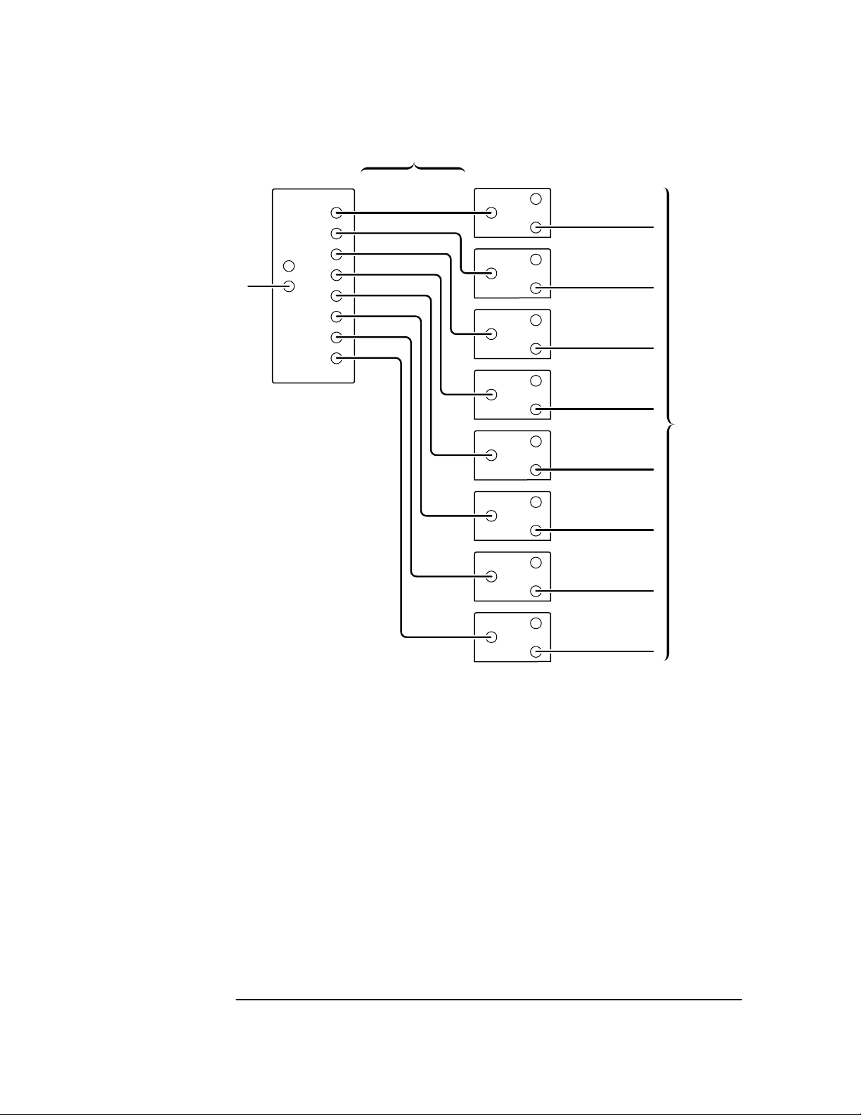
Typical Timing Signal Distribution System
The following block diagram illustrates how the 59552A distribution
amplifier and the 59553A receiver can be connected for a typical
application requiring distribution of one pulse per second (1 PPS) and
IRIG-B time code. The 59553A ensures an identical, synchronous clock
signal and precise time of day at each distribution point. In addition to
connecting the 59552A and 59553A as shown in the block diagram, you
may need to configure both the 59552A and 59553A by positioning
internal jumpers (refer to Chapter 2, “Configuring Your
59552A/59553A”). You will also need to connect power to each unit
(refer to the section titled “Preparing the 59552A/59553A for Use” in
this chapter).
Coaxial
Cables
IRIG Input
1PPS Input
59552A
Fiber-Optic
Distribution
Amplifier
ch1
ch2
ch3
ch4
ch5
ch6
ch7
ch8
Fiber-Optic
Cables
Combined Signal
59553A
Fiber-Optic
Receivers
(Eight)
Coaxial
Cables
Analog Out (IRIG)
Digital Out (1PPS)
To
System
1-2 User’s Guide
Page 11

Chapter 1 Getting Started
59552A Front Panel at a Glance
59552A Front Panel at a Glance
1 When the Power indicator is illuminated,
it indicates that input power is supplied to the
59552A.
2 When the Digital In (1 PPS) indicator is flashing
on and off, it indicates that the 59552A is
receiving the 1 PPS (1 Pulse Per Second)
signal typically from the 59551A GPS
Measurements Synchronization Module.
3 When the Analog In (IRIG) indicator is
illuminated, it indicates that the 59552A is
receiving the IRIG-B signal typically from the
59551A GPS Measurements Synchronization
Module.
User’s Guide 1-3
Page 12

Chapter 1 Getting Started
59552A Rear Panel at a Glance
59552A Rear Panel at a Glance
1 Digital In (1 PPS) BNC connector for receiving
the 1 Pulse Per Second signal typically from
the 59551A GPS Measurements
Synchronization Module.
2 Analog In (IRIG) connector for receiving the
IRIG-B signal typically from the 59551A GPS
Measurements Synchronization Module.
3 AC POWER input jack. The AC input jack is
standard. The unit operates from ac voltage.
It can also be operated from dc voltage via this
ac jack by using the supplied IEC 320 dc
connector plug.
4 Frame-ground stud for chassis-ground
connection.
5 OUTPUTS fiber-optic connectors (metal ST) for
transmitting the results of the two-signal
combined (1 PPS and IRIG) or the one-signal
digital (1 PPS) to the 59553A Fiber-Optic
Receiver.
1-4 User’s Guide
Page 13

Chapter 1 Getting Started
59553A Front Panel at a Glance
59553A Front Panel at a Glance
59553A
FIBEROPTIC RECEIVER
Power Digital In
1 23
STATUS
(1PPS)
Analog In
(IRIG)
1 When the Power indicator is illuminated, it
indicates that input power is supplied to the
59553A.
2 When the Digital In (1 PPS) indicator is flashing
on and off, it indicates that the 59553A is
receiving the 1 PPS (1 Pulse Per Second)
signal from the 59552A Fiber-Optic
Distribution Amplifier.
3 When the Analog In (IRIG) indicator is
illuminated, it indicates that the 59553A is
receiving the IRIG-B signal from the 59552A
Fiber-Optic Distribution Amplifier.
User’s Guide 1-5
Page 14

Chapter 1 Getting Started
59553A Rear Panel at a Glance
59553A Rear Panel at a Glance
1
SERIAL PLATE
CAUTION
METRIC & INCH HARDWARE
WARNING:
To avoid electric shock:
Do not remove covers.
No user serviceable parts
inside.
Refer all servicing to qualified
personnel.
This unit must be earth
grounded.
5
1 AC POWER input jack. The AC input jack is
standard. The unit operates from ac voltage.
It can also be operated from dc voltage via this
ac jack by using the supplied IEC 320 dc
connector plug.
2 Fiber Optic In fiber-optic connectors (metal ST)
for receiving the transmitted results of the
two-signal combined (1 PPS and IRIG) or the
one-signal digital (1 PPS) from the 59552A
Fiber-Optic Distribution Amplifier.
~AC POWER
120-240 VAC 50/60 Hz
Digital
Out
(1PPS)
! !
50 VA
MAX
Analog
Out
(IRIG)
CAUTION:
For continued
protection
against fire,
!
replace only
with fuse
of same type
and ratings.
Fiber
Optic
In
4 3 2
3 Analog Out (IRIG) BNC connector for outputting
the signal to the system.
4 Digital Out (1 PPS) BNC connector for outputting
the signal to the system.
5 Frame-ground stud for chassis-ground
connection.
1-6 User’s Guide
Page 15

Chapter 1 Getting Started
Preparing the 59552A/59553A for Use
Preparing the 59552A/59553A for Use
To Connect AC Power
The ac power module or jack senses incoming voltage and
automatically selects the proper setup. Just connect the
59552A/59553A to the ac power source using the supplied power cord.
User’s Guide 1-7
Page 16

Chapter 1 Getting Started
Preparing the 59552A/59553A for Use
To Assemble and Connect the +129 Vdc IEC 320
Connector/Cable
The 59552A/59553A is operated from ac voltage. It can also be operated
from 129 Vdc. Note that you will have to assemble your own dc power
cable using 18 AWG connecting wires and the supplied IEC 320 dc
connector plug as shown in Figure 1-1A.
1 Cover screw 6 Cable sleeve
2 Top cover 7 Cable (customer supplies)
3 Negative (low voltage) terminal 8 Wire clamp
4 Chassis ground terminal 9 Bottom cover
5 Positive (high voltage) terminal 10 Wire clamp screws
Figure 1-1A. 129 Vdc IEC 300 DC Connector Plug and Power Cable
Exploded View
1 Using a small flat blade screwdriver, open the connector by loosening
the cover center screw (1) that holds the two covers (2, 9) of the
connector plug together as shown in Figure 1-1A.
2 Using a small flat blade screwdriver, pry loose contact terminals 3, 4,
and 5 from the bottom cover (9) of the connector plug.
1-8 User’s Guide
Page 17

Chapter 1 Getting Started
Preparing the 59552A/59553A for Use
3 Slide the cable sleeve (6) over the cable (7).
4 Loosen the screw of 5 (L) terminal, and connect the positive (high)
voltage wire to the terminal.
The “L” terminal marking is inscribed inside the bottom cover (9).
5 Tighten screw. Soldering is not necessary.
6 Loosen the screw of 3 (N) terminal, and connect the negative (low)
voltage wire to the terminal.
The “N” terminal marking is inscribed inside the bottom cover (9).
7 Tighten screw. Soldering is not necessary.
8 Loosen the screw of 4 ( ) terminal, and connect the ground (chassis)
wire to the terminal.
The “ ” terminal marking is inscribed inside the bottom cover (9).
9 Tighten screw. Soldering is not necessary.
10 With the wires connected to the terminals (3, 4, and 5), re-insert the
terminal in their proper positions in the bottom cover (9).
11 Make sure that the cable sleeve’s (6) brim is placed in the groove or slot
in the bottom cover (9).
12 Clamp the wires down using the wire clamp (8). Position the clamp and
over the wires and attach and secure it to bottom cover (9) by
tightening the two screws (10).
At this point, your connector plug and cable assembly should look
similar to Figure 1-1B.
User’s Guide 1-9
Page 18

Chapter 1 Getting Started
Preparing the 59552A/59553A for Use
1 Cover screw 4 Wire clamp screws
2 Top cover 5 Wire clamp
3 Cable sleeve 6 Bottom cover
Figure 1-1B. 129 Vdc DC Power Cable Assembly
13 As shown in Figure 1-1B, join the two covers (2, 6) by properly
positioning them together and tightening the wire clamp screws (4).
14 Finally, secure the two covers by tightening the cover screw (1).
15 Observing the correct polarity, attach the other ends of the wires to a
proper dc power source to operate the Module.
1-10 User’s Guide
Page 19

2
Configuring Your 59552A/59553A
Page 20

Chapter 2 Configuring Your 59552A/59553A
Chapter Contents
Chapter Contents
This chapter provides configuration procedures with overview
information for the 59552A/59553A.
This chapter is organized as follows:
• Introduction page 2-3
• Removing the Covers page 2-5
– To Remove 59552A Cover page 2-5
– To Remove 59553A Cover page 2-6
• Configuring for One-Signal Distribution
(Digital Mode Operation) page 2-9
– Overview of the Digital Mode page 2-9
– To Configure the 59552A and 59553A for Digital
Mode Operation page 2-11
• Configuring for Two-Signal Distribution
(Combined Mode Operation) page 2-16
– Overview of Combined Mode page 2-16
– To Configure the 59552A and 59553A for Combined
Mode Operation page 2-18
2-2 User’s Guide
Page 21

Chapter 2 Configuring Your 59552A/59553A
Introduction
Introduction
There are two ways the 59552A Fiber-Optic Distribution Amplifier and
the 59553A Fiber-Optic Receiver can be configured to distribute
signals.
• Digital Mode configuration, which distributes one digital signal,
(i.e., a 1 PPS signal).
• Combined Mode configuration, which distributes two signals:
one analog and one digital (i.e., the IRIG-B and 1 PPS signals,
respectively).
NOTE The factory configures the instruments for Combined Mode operation.
Selection of Digital Mode operation requires reconfiguration of both the
59552A and 59553A by repositioning of internal jumpers, as shown in
tables 2-1 and 2-2.
If your application requires transmission of only one digital signal,
use the Digital Mode. Digital Mode passes signals with minimal delay
compared with those associated with combining digital and analog
information. The timing of both rising and falling edges are preserved.
Table 2-1 summarizes the factory default two-signal or Combined Mode
configuration. Table 2-2 summarizes the one-signal or Digital Mode
configuration.
User’s Guide 2-3
Page 22

Chapter 2 Configuring Your 59552A/59553A
Introduction
Table 2-1. 59552A/59553A Two-Signal Configuration
Feature
Mode
Digital Input On-Time Edge Rising Edge of Input
Input Impedance, Analog
Input Impedance, Digital 50 Ohms to GND
Digital Output On-Time
Edge
* The boldfaced choices in this column indicate the factory defaults.
*
Choices Factory 59552A Jumpers 59553A Jumpers
Combined (two signals)
Falling Edge of Input P7 2,3
600 Ohms
10 kilohm P3 1,2
1 kilohm to +5 Volts P4 2,3
Rising Edge at Output
Falling Edge at Output P3 2,3
Default
(!)
!
!
!
!
!
Pin
Jumper
P5 1,2 P4 1,2
P6 1,2
P7 1,2
P8 1,2
P8 2,3
P3 2,3
P4 1,2
Position Jumper
P3 1,2
Pin
Position
Table 2-2. 59552A/59553A One-Signal Configuration
Feature
Mode Digital (one signal) P5 2,3 P4 2,3
Digital Input Conditioning
Input Impedance, Analog Input unused
Input Impedance, Digital
Digital Output Conditioning
* The boldfaced choices in this column indicate the factory defaults.
** Both the rising and falling edges are preserved.
*
Choices Factory 59552A Jumpers 59553A Jumpers
Default
(!)
Output replicates input
!
!
50 Ohms to GND
1 kilohm to +5 Volts P4 2,3
**
Rising Edge at Output
!
!
Jumper
P6 2,3
P7 1,2
P8 1,2
P3 2,3
P4 1,2
Pin
Position Jumper
P3 1,2
The following sections describe how to configure your amplifier and
receiver for your application.
Pin
Position
2-4 User’s Guide
Page 23

Chapter 2 Configuring Your 59552A/59553A
Removing the Covers
Removing the Covers
Tools Required
The following tools are required for these removal procedures:
• Hand TORX® 10 screwdriver (T10)—for 59553A
• Hand TORX® 15 screwdriver (T15)—for 59552A
To Remove 59552A Cover
The following procedure tells you how to remove the cover from the
59552A Fiber-Optic Distribution Amplifier. The cover is removed to
access the jumpers.
WARNING WHEN THE COVER IS REMOVED FROM THE INSTRUMENT,
LINE VOLTAGES ARE EXPOSED WHICH ARE DANGEROUS
AND MAY CAUSE SERIOUS INJURY IF TOUCHED.
DISCONNECT POWER.
1 Remove the power cord from the 59552A.
2 To remove the rear bezel, loosen the captive screws on the sides as
shown in Figure 2-1 using the TORX 15 screwdriver.
Analog In (IRIG) Digital In (1PPS)
Ch 1 Ch 2 Ch 3 Ch 4 Ch 5 Ch 6 Ch 7 Ch 8
!!
SERIAL PLATE
OUTPUTS
~AC POWER
120-240 VAC 50/60 Hz
!
50 VA
MAX
WARNING:
This unit must
be earth grounded.
CAUTION:
METRIC & INCH
HARDWARE
CONSULT SERVICE
MANUAL
!
Figure 2-1. Rear Bezel Removal (59552A)
3 Remove the screw located at the bottom near the rear of the cover as
shown in Figure 2-2.
User’s Guide 2-5
Page 24

Chapter 2 Configuring Your 59552A/59553A
Removing the Covers
WARNING:
WARNING:
FOR CONTINUED FIRE PROTECTION, USE SPECIFIED ~ LINE FUSE.
FOR CONTINUED FIRE PROTECTION, USE SPECIFIED ~ LINE FUSE.
C
C
h
h
1
1
!
!
C
C
h
h
2
2
C
C
h
h
3
3
C
C
h
!
h
4
!
4
H
H
O
O
U
U
T
T
C
P
C
P
U
h
M
U
h
5
M
T
a
5
T
S
a
d
S
d
e
e
in
in
U
U
.S
.S
C
.A
C
h
.A
h
. b
6
. b
6
y
y
120-240 VAC 50/60 Hz
120-240 VAC 50/60 Hz
C
C
h
h
7
7
!
!
C
C
h
h
8
8
M
M
A
A
N
C
N
U
C
O
MAX
U
A
O
MAX
N
A
L
N
S
L
U
S
U
L
H
T
L
50 VA
H
A
T
50 VA
S
A
R
E
S
M
R
D
R
E
M
E
D
W
R
V
T
E
W
A
I
V
R
C
T
A
I
R
R
C
I
E
C
C
R
E
I
E
!
C
C
E
&
!
A
&
A
I
N
U
I
N
C
U
ER
T
C
H
H
IO
IO
N
N
:
:
g
r
g
o
r
u
o
n
m
u
d
n
m
u
e
d
s
u
d
e
t
s
.
d
t
.
IN
IN
G
G
:
:
N
N
E
E
L
L
.
.
IN
T
IN
G
G
T
T
O
b
O
S
e
b
S
e
e
E
T
a
e
E
r
h
R
T
a
t
i
r
h
h
R
s
V
t
i
h
s
V
u
IC
n
u
IC
W
i
n
t
E
W
i
t
E
T
A
T
A
R
R
R
R
A
N
A
IN
N
IN
E
E
D
D
P
P
E
E
R
R
S
S
O
O
N
N
~AC POWER
~AC POW
S
S
E
E
R
R
V
V
IC
IC
S
S
E
E
)
R
)
R
IA
IA
L
L
P
P
L
L
A
A
IC
T
IC
T
E
E
E
E
A
A
B
B
L
L
E
E
P
P
A
A
R
R
T
T
S
S
IN
IN
S
S
ID
ID
E
E
, R
, R
E
E
F
F
E
E
R
R
D
D
ig
ig
ital In
ita
l In
(1P
W
(1
W
P
A
P
A
P
S
R
S
R
)
N
)
N
IN
IN
G
A
G
A
n
:
n
alo
:
a
N
lo
N
O
g
O
g
In
O
In
O
(IR
P
(IR
P
E
E
R
IG
R
IG
A
A
T
T
O
O
R
R
S
S
E
E
R
R
V
V
Figure 2-2. Bottom View for Cover Removal (59552A)
4 With one hand gripping the front bezel, pull the cover off with the
other hand by sliding the cover backward.
To Remove 59553A Cover
The following procedure tells you how to remove the cover from the
59553A Fiber-Optic Receiver. The cover is removed to access the
jumpers.
WARNING WHEN THE COVER IS REMOVED FROM THE INSTRUMENT,
LINE VOLTAGES ARE EXPOSED WHICH ARE DANGEROUS
AND MAY CAUSE SERIOUS INJURY IF TOUCHED.
DISCONNECT POWER.
1 Remove the power cord from the 59553A.
2 Remove two screws on each side of the 59553A as shown in Figure 2-3
using the TORX 10 screwdriver.
2-6 User’s Guide
Page 25

Chapter 2 Configuring Your 59552A/59553A
Removing the Covers
H
H
59553A
Power
5
5
Power
Power
9553A
9553A
FIBEROPTIC RECEIVER
FIBEROPTIC RECEIVER
FIBEROPTIC RECEIVER
S
S
S
T
T
T
A
A
A
Digital In
T
Digital In
Digital In
T
T
U
U
U
S
S
S
(1PPS)
(1PPS)
(1PPS)
Analog In
Analog In
Analog In
(IRIG)
(IRIG)
(IRIG)
Figure 2-3. Removing Screws in the Cover (59553A)
3 Lift cover off the 59553A as shown in Figure 2-4.
User’s Guide 2-7
Page 26

Chapter 2 Configuring Your 59552A/59553A
Removing the Covers
59553A
Power
FIBEROPTIC RECEIVER
S
T
A
Digital In
T
U
S
(1PPS)
Analog In
(IRIG)
Figure 2-4. Removing the Cover (59553A)
UR
0
9
1
3
1
E
COMPONENT TYPE
5
CUSTOM RECTIFIER
t
r
a
u
a
V
B
t
f
U
u
r
T
p
e
g
LR85805
LEVEL 3
2-8 User’s Guide
Page 27

Chapter 2 Configuring Your 59552A/59553A
Configuring for One-Signal Distribution (Digital Mode Operation)
Configuring for One-Signal Distribution
(Digital Mode Operation)
Overview of the Digital Mode
As shown in Figure 2-5, the Digital Mode provides for distribution of
one signal. The signal is typically the 1 PPS output from the 59551A
GPS Measurements Synchronization Module. The signal is connected
to the Digital In (1 PPS) BNC connector of the 59552A Fiber-Optic
Distribution Amplifier via a BNC cable where the signal is distributed
to each of the eight fiber-optic outputs of the 59552A (Ch 1 through
Ch 8). Using a fiber-optic cable, each of these outputs can be connected
to the Fiber Optic In connector of an 59553A Fiber-Optic Receiver.
Finally, the 1 PPS signal is output at the Digital Out (1 PPS) BNC
connector of each 59553A to supply the timing signals to the system.
Digital Mode is intended to transmit a single digital signal.
The distribution system output replicates the system input. Waveform
characteristics such as pulse widths are preserved, with no inversion.
The system can transmit digital signals at rates from dc to 5 MBAUD.
Distribution delay depends primarily on the length of fiber line used.
The 2 microsecond delay typical of Combined Mode is not present for
Digital Mode, because the single digital signal does not use the
two-signal combining hardware.
User’s Guide 2-9
Page 28
1PPS Input
1PPS Input
Chapter 2 Configuring Your 59552A/59553A
Configuring for One-Signal Distribution (Digital Mode Operation)
Fiber-Optic
HP 59552A
59552A
Fiber-Optic
Fiber-Optic
Distribution
Distribution
Amplifier
Amplifier
ch1
ch1
ch2
ch2
ch3
ch3
ch4
ch4
ch5
ch5
ch6
ch6
ch7
ch7
ch8
ch8
Fiber-Optic
Cables
Cables
Digital Signal
Digital Signal
HP 59553A
59553A
Fiber-Optic Receivers
Fiber-Optic Receivers
(Eight)
(Eight)
Digital Out (1PPS)
Digital Out (1PPS)
To
To
System
System
Figure 2-5. Block Diagram of One-Signal Digital Mode Operation
(Using Eight 59553As)
2-10 User’s Guide
Page 29

Chapter 2 Configuring Your 59552A/59553A
Configuring for One-Signal Distribution (Digital Mode Operation)
To Configure the 59552A and 59553A for Digital Mode
Operation
Perform the following procedures to configure the 59552A Fiber-Optic
Distribution Amplifier for Digital Mode operation.
Configuring the 59552A for Digital Mode
1 Remove the cover.
See the section titled “Removing the Covers.”
2 In the 59552A, place both jumpers P5 and P6 in the pins 2,3 position
(i.e., pins 2 and 3 shorted or connected together) as shown in
Figure 2-6.
3 Place both jumpers P7 and P8 in the pins 1,2 position as shown in
Figure 2-6.
4 Place jumper P3 in the pins 2,3 position (the 600 Ω input impedance
default position for the Analog In (IRIG) input) as shown in Figure 2-6.
5 If you require a 50 Ω load applied to the Digital In (1 PPS) input, place
jumper P4 in the pins 1,2 position as shown in Figure 2-6.
If you do not require a 50 Ω load applied to the Digital In (1 PPS) input,
place jumper P4 in the pins 2,3 position.
6 Re-install the cover by performing the cover removal procedure in
reverse.
7 Perform the procedure in the following section on each 59553A
Fiber-Optic Receiver to complete the Digital Mode configuration.
User’s Guide 2-11
Page 30

Chapter 2 Configuring Your 59552A/59553A
Configuring for One-Signal Distribution (Digital Mode Operation)
600 ohm
2 to 3
123
P3
50 ohm
1 to 2
P4
123
123
P5
DIGITAL
2 to 3
DIGITAL and ANALOG
1 to 2
123
P6
DIGITAL
2 to 3
DIGITAL and ANALOG
1 to 2
P8
123
EDGE-
2 to 3
EDGE+
1 to 2
P7
123
EDGE2 to 3
EDGE+
1 to 2
Figure 2-6. 59552A Digital Mode Jumper Locations
2-12 User’s Guide
Page 31

Chapter 2 Configuring Your 59552A/59553A
Configuring for One-Signal Distribution (Digital Mode Operation)
Configuring the 59553A for Digital Mode
1 Remove the cover.
See the section titled “Removing the Covers.”
2 In the 59553A, place jumper P3 in its pins 1,2 default position as
shown in Figure 2-7.
3 Place jumper P4 in the pins 2,3 position to select one-signal
transmission as shown in Figure 2-7.
P3
1 to 2 +PULSE
2 to 3 -PULSE
P4
3
2
1
2
1
1 to 2 PULSE
2 to 3 DIGITAL
3
P3
1 to 2 +PULSE
2 to 3 -PULSE
E131905
B
TUV
g
e
321
UR
COMPONENT TYPE
CUSTOM RECTIFIER
u
a
a
r
t
t
f
u
p
r
P4
LR85805
LEVEL 3
1 to 2 PULSE
2 to 3 DIGITAL
321
Figure 2-7. 59553A Digital Mode Jumper Locations
User’s Guide 2-13
Page 32

Chapter 2 Configuring Your 59552A/59553A
Configuring for One-Signal Distribution (Digital Mode Operation)
4 Re-install the cover by performing the cover removal procedure in
reverse.
5 Now, connect the units as shown in Figure 2-8.
This completes the One-Signal Distribution (Digital Mode Operation)
configuration procedure.
2-14 User’s Guide
Page 33

Chapter 2 Configuring Your 59552A/59553A
Configuring for One-Signal Distribution (Digital Mode Operation)
59551A
GPS
Measurements
Synchronization
Module
(Rear Panel)
59552A
Fiber-Optic
Distribution
Amplifier
(Rear Panel)
59553A
Fiber-Optic Receivers
(Rear Panel)
1PPS
Ch 1 Ch 2 Ch 3 Ch 4 Ch 5 Ch 6 Ch 7 Ch 8
!
Digital Out 1PPS
To
System
Figure 2-8. One-Signal Digital Mode Hookup (Using Eight 59553As)
User’s Guide 2-15
Page 34

Chapter 2 Configuring Your 59552A/59553A
Configuring for Two-Signal Distribution (Combined Mode Operation)
Configuring for Two-Signal Distribution
(Combined Mode Operation)
Overview of Combined Mode
As shown in Figure 2-9, the Combined Mode provides for distribution
of two signals. The signals are the 1 PPS (digital) and IRIG-B (analog)
outputs from the 59551A GPS Measurements Synchronization Module.
The signals are connected to the Digital In (1PPS) and Analog IN (IRIG)
connectors of the 59552A Fiber-Optic Distribution Amplifier via BNC
cables. These signals are distributed to each of the eight fiber-optic
outputs of the 59552A (Ch 1 through Ch 8). Using fiber-optic cables,
each of these outputs can be connected to the Fiber Optic In connector
of an 59553A Fiber-Optic Receiver. Finally, the combined signals are
output at the Digital Out (1 PPS) and Analog Out (IRIG) connectors of
the 59553A to supply timing signals to a system.
The on-time edge of the Digital Out (1 PPS) at the 59553A output is
delayed approximately 2 microseconds through the distribution
amplifier and receiver hardware. Additional delay attributable to
transmission through fiber will depend on the fiber line used.
Independent of your choice for the amplifier input, you can select the
on-time edge: either the rising or falling edge of 59552A amplifier
input. The system is configured at the factory to use the rising edge as
the on-time edge.
You can select whether the on-time edge is produced as a rising or
falling edge at the output of the 59553A Fiber-Optic Receiver.
The system is configured at the factory to transmit a rising edge as the
on-time edge.
Regardless of the pulse polarity selected, the pulse width is fixed at
approximately 70 microseconds.
The system transmits the IRIG analog signal unmodified, with
minimal delay.
2-16 User’s Guide
Page 35

Chapter 2 Configuring Your 59552A/59553A
Configuring for Two-Signal Distribution (Combined Mode Operation)
IRIG Input
1PPS Input
59552A
Fiber-Optic
Distribution
Amplifier
ch1
ch2
ch3
ch4
ch5
ch6
ch7
ch8
Fiber-Optic
Cables
Combined Signal
59553A
Fiber-Optic Receivers
(Eight)
Analog Out (IRIG)
Digital Out (1PPS)
To
System
Figure 2-9. Block Diagram of Two-Signal Combined Mode Operation
(Using Eight 59553As)
User’s Guide 2-17
Page 36

Chapter 2 Configuring Your 59552A/59553A
Configuring for Two-Signal Distribution (Combined Mode Operation)
NOTE The 59552A and 59553A are shipped from the factory configured for
Combined Mode Operation. You need to perform these procedures only
if the instruments have reconfigured since receipt.
To Configure the 59552A and 59553A for Combined
Mode Operation
Perform the following procedures to configure the 59552A Fiber-Optic
Distribution Amplifier for Combined Mode operation.
Configuring the 59552A for Combined Mode Operation
1 Remove the cover.
See the section titled “Removing the Covers.”
2 In the 59552A, place both jumpers P5 and P6 in the pins 1,2 position
(i.e., pins 1 and 2 shorted or connected together) as shown in
Figure 2-10.
3 To select whether the on-time edge is the rising or the falling edge of
the 1 PPS signal input to the 59552A, set jumpers P7 and P8
depending on your on-time edge requirement.
If you require the rising edge of the 1 PPS input as the on-time edge,
place both jumpers P7 and P8 in the pins 1,2 position as shown in
Figure 2-10.
If you require the falling edge of the 1 PPS (digital) input as the
on-time edge, place both jumpers P7 and P8 in the pins 2,3 position.
4 If you require a 600 Ω input impedance for the IRIG (analog) input,
place jumper P3 in the pins 2,3 position as shown in Figure 2-10.
If you require a 10 kΩ input impedance for the IRIG (analog) input,
place jumper P3 in the pins 1,2 position.
5 If you require a 50 Ω load applied to the Digital In (1 PPS) input, place
jumper P4 in the pins 1,2 position as shown in Figure 2-10.
If you do not require a 50 Ω load applied to the Digital In (1 PPS) input,
place jumper P4 in the pins 2,3 position.
6 Re-install the cover by performing the cover removal procedure in
reverse.
2-18 User’s Guide
Page 37

Chapter 2 Configuring Your 59552A/59553A
Configuring for Two-Signal Distribution (Combined Mode Operation)
7 Perform the procedure in the following section on each 59553A
Fiber-Optic Receiver to complete the Combined Mode configuration.
600 ohm
2 to 3
123
P3
50 ohm
1 to 2
P4
123
123
P5
DIGITAL
2 to 3
DIGITAL and ANALOG
1 to 2
123
P6
DIGITAL
2 to 3
DIGITAL and ANALOG
1 to 2
P8
123
EDGE2 to 3
EDGE+
1 to 2
P7
123
EDGE-
2 to 3
EDGE+
1 to 2
Figure 2-10. 59552A Combined Mode Jumper Locations
User’s Guide 2-19
Page 38

Chapter 2 Configuring Your 59552A/59553A
Configuring for Two-Signal Distribution (Combined Mode Operation)
Configuring the 59553A for Combined Mode Operation
1 If you need to set the rising edge of the 1 PPS output to correspond
with on-time edge (system output is a positive pulse), place jumper P3
in its pins 1,2 default position as shown in Figure 2-11.
If you need to set the falling edge of the 1 PPS output to correspond
with on-time edge (system output is a negative pulse), place jumper P3
in its pins 2,3 position.
2 Place jumper P4 in the pins 1,2 position to select two-signal
transmission as shown in Figure 2-11.
P3
1 to 2 +PULSE
2 to 3 -PULSE
P4
3
2
1
2
1
1 to 2 PULSE
2 to 3 DIGITAL
3
P3
1 to 2 +PULSE
2 to 3 -PULSE
E131905
B
TUV
g
e
321
UR
COMPONENT TYPE
CUSTOM RECTIFIER
u
a
a
r
t
t
f
u
p
r
P4
LR85805
LEVEL 3
1 to 2 PULSE
2 to 3 DIGITAL
321
Figure 2-11. 59553A Combined Mode Jumper Locations
3 Re-install the cover by performing the cover removal procedure in
reverse.
4 Now, connect the units as shown in Figure 2-12.
This completes the Two-Signal Distribution (Combined Mode
Operation) configuration procedure.
2-20 User’s Guide
Page 39

Chapter 2 Configuring Your 59552A/59553A
Configuring for Two-Signal Distribution (Combined Mode Operation)
59551A
GPS
Measurements
Synchronization
Module
(Rear Panel)
IRIG
1PPS
59552A
Fiber-Optic
Distribution
Amplifier
(Rear Panel)
Ch 1 Ch 2 Ch 3 Ch 4 Ch 5 Ch 6 Ch 7 Ch 8
Ch 1 Ch 2 Ch 3 Ch 4 Ch 5 Ch 6 Ch 7 Ch 8
59553A
Fiber-Optic Receivers
(Rear Panel)
!
!
Analog Out (IRIG)
Digital Out 1PPS
Digital Out 1PPS
To
System
Figure 2-12. Two-Signal Combined Mode Hookup (Using Eight
59553As)
User’s Guide 2-21
Page 40

Chapter 2 Configuring Your 59552A/59553A
Configuring for Two-Signal Distribution (Combined Mode Operation)
2-22 User’s Guide
Page 41

3
Operational Verification
Page 42

Chapter 3 Operational Verification
Chapter Contents
Chapter Contents
This chapter provides the operational verification procedures, which
are an abbreviated series of checks that may be performed to give a
high degree of confidence that the instrument is operating properly
without performing the complete performance tests. An operational
verification is useful for incoming inspection, routine maintenance,
and after instrument repair.
This chapter is organized as follows:
• Introduction page 3-3
• Equipment Required page 3-3
• 59552A/59553A Operational Verification page 3-4
– Setup page 3-4
– Digital Out (1 PPS) and Analog (IRIG) Out
Waveform Tests page 3-5
– LED Indicator Test page 3-6
3-2 User’s Guide
Page 43

Chapter 3 Operational Verification
Introduction
Introduction
The 59552A Fiber-Optic Distribution Amplifier and the 59553A
Fiber-Optic Receiver are designed to be used together for the
conversion/transmission/reception/re-conversion of 1 PPS (digital) and
IRIG-B (analog) signals. Because of this tandem relationship,
the operational verification will require that at least one each of the
59552A and 59553A be available, plus a nominal length of metal ST
fiber optic cable for connecting the two instruments.
For more information on connections and power supply requirements,
refer to Chapter 1, “Getting Started,” in this guide.
Equipment Required
The test equipment listed in Table 3-1 is necessary to perform the
Operational Verification. The suggested HP model number (or
equivalent) will ensure that the equipment has the necessary
characteristics to perform the test.
You may substitute any other equipment provided that it has the same
or better specifications for the function in use.
Table 3-1. Recommended Test Equipment for Operational
Verification.
Description HP Model Number
Function Generator/Arbitrary Waveform
Generator as a 1 PPS source
Function Generator/Arbitrary Waveform
Generator as a 1 kHz source
Digital Oscilloscope HP 54600B (or equivalent)
50Ω Coaxial Cable with BNC connectors (4) HP 10503A (or equivalent)
62.5/125 micrometer (um) Fiber Optic Cable
with Metal ST Connectors
50Ω Feedthrough HP 10100C (or equivalent)
HP 33120A (or equivalent)
HP 33120A (or equivalent)
User’s Guide 3-3
Page 44

Chapter 3 Operational Verification
59552A/59553A Operational Verification
59552A/59553A Operational Verification
This test will require that all eight fiber-optic outputs (Ch 1 through
Ch 8) on the 59552A be tested.
Setup
1 Ensure that both the 59552A and 59553A are set to the factory default
two-signal combined operation.
Refer to Chapter 2, “Configuring Your 59552A/59553A,” in this guide
for assistance in determining this operating mode. If each of the
instruments was directly received from the factory, these defaults
should already be set up.
2 Connect the equipment as shown in Figure 3-1 to begin testing of the
first fiber-output channel (Ch 1) of the 59552A.
Analog Out (IRIG)
Digital Out (1 PPS)
HP 33120A
Function Genertor/
Arbitrary Waveform Generator
HP 33120A
Function Genertor/
Arbitrary Waveform Generator
59553A
Fiber-Optic Receiver
(Rear Panel)
BNC Cable
Fiber
Optic
In
HP 54600B
Oscilloscope
Digital In
(1 PPS)
Ch 1
Fiber-Optic
Cable
50Ω Feedthrough
(HP 10100C)
59552A
Fiber-Optic Distribution Amplifier
(Rear Panel)
Analog In (IRIG)
BNC Cable
Figure 3-1. Operational Verification Setup
3-4 User’s Guide
Page 45

Chapter 3 Operational Verification
59552A/59553A Operational Verification
Digital Out (1 PPS) and Analog (IRIG) Out Waveform
Tests
1 Set the HP 33120A (the one that connects to the 59552A’s
Digital In (1 PPS) input) to provide a 1 PPS signal by setting its
controls as follows:
a. Press Square Wave function key.
b. Press Freq key, then Enter Number key.
c. Using the appropriate number keys, enter in the value 1Hz.
d. Press the blue Shift, then %Duty key.
e. Press the ∨ (decrease) key until 20% is displayed.
f. Press Ampl key, then Enter Number key.
g. Enter in the value 5.0 Vpp.
h. Press Offset key, then Enter Number key.
i. Enter in the value 2.5 V.
2 Set the other HP 33120A to output a 1 kHz sine wave with a 1 Vp-p
amplitude by setting its controls as follows:
a. Press Sine Wave function key.
b. Press Freq key, then Enter Number key.
c. Using the appropriate number keys, enter in the value 1 KHz.
d. Press Ampl key, then Enter Number key.
e. Enter in the value 1.0 Vpp.
3 Set the Channel 2 input of the HP 54600B Oscilloscope to dc coupled,
vertical 1 Volt/div, sweep 10 µsec/div, and positive trigger.
4 Verify the presence of a 1 PPS signal on Channel 2.
5 Set the Channel 1 input of the HP 54600B Oscilloscope to dc coupled,
vertical 1 Volt/div, and sweep 100 msec/div.
6 Verify the presence of a 1 kHz sine wave on Channel 1.
7 Connect the next fiber-optic output of the 59552A to the 59553A and
repeat steps 4 and 6 until all 8 ports on the 59552A have been verified.
User’s Guide 3-5
Page 46

Chapter 3 Operational Verification
59552A/59553A Operational Verification
LED Indicator Test
1 Verify that the front-panel Digital In (1PPS) LED is flashing on both
the 59552A and the 59553A.
2 Verify that the Analog In (IRIG) LED is illuminated for both the
59552A and the 59553A.
This completes the 59552A/59553A Operational Verification.
3-6 User’s Guide
Page 47

4
Specifications
Page 48

Chapter 4 Specifications
Introduction
Introduction
Both warranted specifications and operating characteristics for the
59552A and 59553A are provided in this chapter. To distinguish
warranted specifications from operating characteristics, the word
“nominal” appears next to a characteristic.
4-2 User’s Guide
Page 49

Chapter 4 Specifications
Introduction
Configuration
Information
There are two ways the 59552A
and 59553A fiber-optic products
can be configured to distribute
signals.
1. The “Combined Mode”
configuration distributes two
signals, one analog and one
digital (such as IRIG-B and
1 PPS respectively).
2. The “Digital Mode” configuration
distributes one digital signal
(such as a 1 PPS signal).
If your application requires
transmission of only one digital
signal, you may choose to use the
Digital Mode. Digital Mode passes
signals with minimal delay
compared to that associated with
combining digital and analog
information.
The factory configures the
instruments for Combined Mode
operation. Selection of Digital Mode
operation requires reconfiguration
of both the 59552A and 59553A by
repositioning of internal jumpers.
Both warranted specifications and
operating characteristics are
covered below. The word “nominal”
appears next to a characteristic to
distinguish it from the warranted
specifications.
System Specifications
Combined Mode
Transmission distance: up to 1 km
Digital edge rate maximum: 1 kHz
Digital edge delay: 2 µs ±5%
(input of 59552A to output of
59553A—excluding delay
through fiber-optic cable; cable
adds approximately 5 ns/meter)
Digital output pulse width: 70 µs
(nominal)
Digital input pulse polarity:
positive or negative (selectable
with internal jumper)
Digital output pulse polarity:
positive or negative (selectable
with internal jumper)
Digital output pulse, risetime/
falltime: less than 5 ns into a
50 Ω load
Digital output short-term jitter:
5 ns rms (nominal) when signal
transmitted 1 km
Analog input frequency range:
10 Hz to 10 kHz
Analog voltage gain: unity
(input of 59552A to output of
59553A driving 600 Ω load)
Digital Mode
Transmission distance: up to 1 km
Digital edge rate maximum: 5 Mbd
Digital edge delay,
rising edge:
120 ns (nominal) plus delay
through fiber-optic cable; cable
adds approximately 5 ns/meter
falling edge:
85 ns (nominal) plus delay
through fiber-optic cable; cable
adds approximately 5 ns/meter
Digital output pulse width: output
replicates input subject to delay
contraints noted above
Digital ouput short-term jitter,
rising edge:
3 ns rms (nominal) when
signal transmitted 1 km
falling edge:
2 ns rms (nominal) when
signal transmitted 1 km
Digital pulse, risetime/falltime: less
than 5 ns
User’s Guide 4-3
Page 50

Chapter 4 Specifications
Introduction
59552A Fiber-Optic
Distribution Amplifier
Inputs:
One digital input typically used as
1 PPS input
One analog input typically used as
IRIG-B123 input
Digital input
Input signal requirements: TTL
Input impedance: 50 Ω to GND
(default) or 1 kΩ to +5 volts
configurable with internal
jumper
Analog input
Input signal requirements:
5 volts peak-to-peak (nominal)
Input impedance: 600 Ω
(default) or 10 kΩ
configurable with internal
jumper
Outputs:
Number of optical outputs: 8
Optical connector: metal ST
Front-panel LEDs indicating:
•Power
• Digital input active
• Analog input active
Note that annunciator is
activated at a minimum voltage
of 1.6 volts pk-pk (nominal)
Power Requirements:
ac Power: 90 to 132 Vac or 198 to
264 Vac, automatically selected;
50 to 60 Hz
or
dc Power: 129 Vdc, 115 to 140 Vdc
operating range
Dimensions:
Height: 88.5 mm
Width: 212.6 mm
Depth: 348.3 mm
Weight: 3 kg
Half-Rack module
59553A Fiber-Optic
Receiver
Inputs:
Number of optical inputs: 1
Optical connector: metal ST
Outputs:
One digital output typically used as
1 PPS output
One analog output typically used as
IRIG-B123 output
Digital output
Output signal: TTL
Output impedance: drives 50 Ω
to GND
Analog Output
Output signal:
5 volts peak-to-peak (nominal)
Output impedance: drives 600 Ω
to GND
Front-panel LEDs indicating:
• Power
• Digital input active
• Analog input active
Note that annunciator is
activated at a minimum voltage
of 1.6 volts pk-pk (nominal)
Power Requirements:
ac Power: 90 to 132 Vac or 198 to
264 Vac, automatically selected;
50 to 60 Hz
or
dc Power: 129 Vdc, 115 to 140 Vdc
operating range
Dimensions:
Height: 87.1 mm
Width: 133.2 mm
Depth: 185.3 mm
Weight: 0.91 kg
Fiber-Optic Cable Core Size
Recommendations:
62.5/125 µm
Ordering Information
59552A
59553A
*129 Vdc operation
*59552A and 59553A come standard with
110, 240 Vac. For use with 129 Vdc
power, assemble and connect your own
cable assembly using the supplied dc
connector plug (1252-5672). See
instructions in Chapter 1.
4-4 User’s Guide
Page 51

Index
NUMERICS
1 PPS, vi, vii, 1-3, 1-4
59551A GPS Measurement
Synchronization Module
59552A rear panel
, 1-4
, vi, 1-3
59552A/59553A specifications and
characteristics
59553A
, 1-6
, 4-2
A
ac power, 1-4, 1-6, 1-7
Analog In (IRIG)
Analog In (IRIG) indicator
Analog Out (IRIG)
, 1-4
, 1-3, 1-5
, 1-6
B
block diagram, 1-2
C
characteristics, 4-2
chassis ground
Combined Mode
, 1-4, 1-6
, 2-3, 2-16
configuring
one-signal distribution, 2-9
configuring the 59552A/59553A
connecting to computer
, 1-8
, 2-3
connector
Analog In
Analog Out (IRIG)
Digital In
Digital Out (1 PPS)
fiber-optic
fiber-optic input
, 1-4
, 1-6
, 1-4
, 1-6
, 1-4
, 1-6
cover
removal, 2-5
removal, 59552A
removal, 59553A
, 2-5
, 2-6
D
dc power, 1-4, 1-6, 1-8
description
59552A
59553A
Digital In (1 PPS)
Digital In (1 PPS) indicator
Digital In (1 PPS) LED
Digital Mode
Digital Out (1 PPS)
disassemble
distribution
two-signal
distribution amplifier
distribution system
, vi
, vii
, 1-4
, 1-3
, 1-3, 1-5
, 2-3
, 1-6
, 2-5
, 2-16
, vi
, 1-2
E
eight fiber-optic outputs, 1-4, 2-9
electrical noise
, vi
F
factory default configuration, 2-3
Fiber Optic In
fiber-optic input connector
fiber-optic outputs
frame ground
, 1-6
, 1-6
, 2-9
, 1-4, 1-6
front panel
distribution amplifier
59552A
59553A
receiver
, 1-3
, 1-5
, 1-5
, 1-3
G
ground, 1-4, 1-6
guide organization
, v
I
in this guide, v
indicator
Analog In (IRIG), 1-3, 1-5
Digital In (1 PPS)
Power
, 1-3, 1-5
input jack
IRIG-B
, 1-4, 1-6
, vi, 1-4
IRIG-B signal
, 1-3, 1-5
, 1-3
J
jumpers, 2-3
L
LED
Analog In (IRIG)
Digital In (1 PPS)
, 1-3, 1-5
Power
LEDs
, vi
, 1-3, 1-5
, 1-3, 1-5
O
one-signal digital, 1-4
one-signal distribution
, 2-9
output
Analog Out (IRIG), 1-6
Digital Out (1 PPS)
fiber-optic
, 1-4
, 1-6
overview
Combined Mode
Digital Mode
one-signal
two-signal
, 2-16
, 2-9
, 2-9
, 2-16
P
power, 1-3
User’s Guide Index-1
Page 52

Index
ac, 1-4, 1-6, 1-7
, 1-4, 1-6, 1-8
dc
Power indicator
power input jack
Power LED
power supply
preface
, v
, 1-3, 1-5
, 1-4, 1-6
, 1-3, 1-5
, 1-4, 1-6
R
rear panel
distribution amplifier
59552A
59553A
receiver
receiver
removing covers
, 1-4
, 1-6
, 1-6
, vii
, 2-5
S
screwdriver
, 2-5
TORX
signal
1 PPS, 1-3
, 1-3
Analog
, 1-3
Digital
IRIG-B
, 1-3
, 1-4
T
Table 2-1, two-signal configuration, 2-4
Table 2-2, one-signal configuration
tools required
TORX screwdriver
two-signal combined
two-signal distribution
typical system
, 2-5
, 2-5
, 1-4
, 2-16
, 1-2
, 2-4
Index-2 User’s Guide
 Loading...