

Page 1

MK1000
MicroKiosk
Product Reference Guide
Page 2

Page 3

MK1000 MicroKiosk
Product Reference Guide
72-53977-01
Revision A
April 2002
Page 4

© 2002 by Symbol Technologies, Inc. All rights reserved.
No part of this publication may be reproduced or used in any form, or by any electrical or
mechanical means, without permission in writing from Symbol. This includes electronic or
mechanical means, such as photocopying, recording, or information storage and retrieval
systems. The material in this manual is subject to change without notice.
The software is provided strictly on an “as is” basis. All software, including firmware,
furnished to the user is on a licensed basis. Symbol grants to the user a non-transferable
and non-exclusive license to use each software or firmware program delivered hereunder
(licensed program). Except as noted below, such license may not be assigned,
sublicensed, or otherwise transferred by the user without prior written consent of Symbol.
No right to copy a licensed program in whole or in part is granted, except as permitted under
copyright law. The user shall not modify, merge, or incorporate any form or portion of a
licensed program with other program material, create a derivative work from a licensed
program, or use a licensed program in a network without written permission from Symbol.
The user agrees to maintain Symbol’s copyright notice on the licensed programs delivered
hereunder, and to include the same on any authorized copies it makes, in whole or in part.
The user agrees not to decompile, disassemble, decode, or reverse engineer any licensed
program delivered to the user or any portion thereof.
Symbol reserves the right to make changes to any software or product to improve reliability,
function, or design.
Symbol does not assume any product liability arising out of, or in connection with, the
application or use of any product, circuit, or application described herein.
No license is granted, either expressly or by implication, estoppel, or otherwise under any
Symbol Technologies, Inc., intellectual property rights. An implied license only exists for
equipment, circuits, and subsystems contained in Symbol products.
Symbol, Spectrum One, and Spectrum24 are registered trademarks of Symbol
Technologies, Inc. Other product names mentioned in this manual may be trademarks or
registered trademarks of their respective companies and are hereby acknowledged.
Symbol Technologies, Inc.
One Symbol Pl aza
Holtsville, New York 11742-1300
http://www.symbol.com
2
Page 5

Contents
About This Guide
Introduction . . . . . . . . . . . . . . . . . . . . . . . . . . . . . . . . . . . . . . . . . . . . . . . . . . . . . . . . . . . . . . . . . . . .ix
Chapter Descriptions. . . . . . . . . . . . . . . . . . . . . . . . . . . . . . . . . . . . . . . . . . . . . . . . . . . . . . . . . . . . .ix
Notational Conventions . . . . . . . . . . . . . . . . . . . . . . . . . . . . . . . . . . . . . . . . . . . . . . . . . . . . . . . . . . . x
Related Publications . . . . . . . . . . . . . . . . . . . . . . . . . . . . . . . . . . . . . . . . . . . . . . . . . . . . . . . . . . . . . x
Service Information . . . . . . . . . . . . . . . . . . . . . . . . . . . . . . . . . . . . . . . . . . . . . . . . . . . . . . . . . . . . . . x
Symbol Support Center . . . . . . . . . . . . . . . . . . . . . . . . . . . . . . . . . . . . . . . . . . . . . . . . . . . . . . .xi
Warranty . . . . . . . . . . . . . . . . . . . . . . . . . . . . . . . . . . . . . . . . . . . . . . . . . . . . . . . . . . . . . . . . . . . . .xiv
Warranty Coverage and Procedure . . . . . . . . . . . . . . . . . . . . . . . . . . . . . . . . . . . . . . . . . . . . . xv
General. . . . . . . . . . . . . . . . . . . . . . . . . . . . . . . . . . . . . . . . . . . . . . . . . . . . . . . . . . . . . . . . . . . xv
Chapter 1. About Your MK1000
Overview . . . . . . . . . . . . . . . . . . . . . . . . . . . . . . . . . . . . . . . . . . . . . . . . . . . . . . . . . . . . . . . . . . . . 1-1
Unpacking Your MK1000. . . . . . . . . . . . . . . . . . . . . . . . . . . . . . . . . . . . . . . . . . . . . . . . . . . . . . . . 1-1
Quick Startup Instructions . . . . . . . . . . . . . . . . . . . . . . . . . . . . . . . . . . . . . . . . . . . . . . . . . . . . . . . 1-2
Parts of the MK1000 . . . . . . . . . . . . . . . . . . . . . . . . . . . . . . . . . . . . . . . . . . . . . . . . . . . . . . . . . . . 1-3
Features of the MK1000 . . . . . . . . . . . . . . . . . . . . . . . . . . . . . . . . . . . . . . . . . . . . . . . . . . . . . . . . 1-4
Buttons and Controls . . . . . . . . . . . . . . . . . . . . . . . . . . . . . . . . . . . . . . . . . . . . . . . . . . . . . . . 1-4
Programmable Function Buttons. . . . . . . . . . . . . . . . . . . . . . . . . . . . . . . . . . . . . . . . . . . 1-4
Reset Button . . . . . . . . . . . . . . . . . . . . . . . . . . . . . . . . . . . . . . . . . . . . . . . . . . . . . . . . . . 1-4
Contrast Control Button. . . . . . . . . . . . . . . . . . . . . . . . . . . . . . . . . . . . . . . . . . . . . . . . . . 1-4
Label/Message Window. . . . . . . . . . . . . . . . . . . . . . . . . . . . . . . . . . . . . . . . . . . . . . . . . . . . . 1-5
Bar Code Scanning . . . . . . . . . . . . . . . . . . . . . . . . . . . . . . . . . . . . . . . . . . . . . . . . . . . . . . . . 1-6
Scanning Modes . . . . . . . . . . . . . . . . . . . . . . . . . . . . . . . . . . . . . . . . . . . . . . . . . . . . . . . 1-6
Changing Scanning Modes . . . . . . . . . . . . . . . . . . . . . . . . . . . . . . . . . . . . . . . . . . . . . . . 1-7
Scanning Guidelines. . . . . . . . . . . . . . . . . . . . . . . . . . . . . . . . . . . . . . . . . . . . . . . . . . . . 1-7
Smart Raster. . . . . . . . . . . . . . . . . . . . . . . . . . . . . . . . . . . . . . . . . . . . . . . . . . . . . . . . . . 1-8
Scanning Composite (2D) Bar Codes . . . . . . . . . . . . . . . . . . . . . . . . . . . . . . . . . . . . . . . 1-9
Specular Reflection. . . . . . . . . . . . . . . . . . . . . . . . . . . . . . . . . . . . . . . . . . . . . . . . . . . . 1-10
Using the Display (LCD). . . . . . . . . . . . . . . . . . . . . . . . . . . . . . . . . . . . . . . . . . . . . . . . . . . . 1-10
Memory. . . . . . . . . . . . . . . . . . . . . . . . . . . . . . . . . . . . . . . . . . . . . . . . . . . . . . . . . . . . . . . . . 1-10
Flash Memory . . . . . . . . . . . . . . . . . . . . . . . . . . . . . . . . . . . . . . . . . . . . . . . . . . . . . . . . 1- 10
Static Random Access Memory (SRAM). . . . . . . . . . . . . . . . . . . . . . . . . . . . . . . . . . . . 1-11
External Ports. . . . . . . . . . . . . . . . . . . . . . . . . . . . . . . . . . . . . . . . . . . . . . . . . . . . . . . . . . . . 1-11
Power Port. . . . . . . . . . . . . . . . . . . . . . . . . . . . . . . . . . . . . . . . . . . . . . . . . . . . . . . . . . . 1-11
Com/Scanner Port. . . . . . . . . . . . . . . . . . . . . . . . . . . . . . . . . . . . . . . . . . . . . . . . . . . . . 1-11
iii
Page 6

MK 1000 MicroKiosk Product Reference Guide
LAN (Local Area Network) Port . . . . . . . . . . . . . . . . . . . . . . . . . . . . . . . . . . . . . . . . . . .1-12
Chapter 2. Setup and Installation: Mechanical
Overview. . . . . . . . . . . . . . . . . . . . . . . . . . . . . . . . . . . . . . . . . . . . . . . . . . . . . . . . . . . . . . . . . . . . .2-1
Wired Ethernet Setup . . . . . . . . . . . . . . . . . . . . . . . . . . . . . . . . . . . . . . . . . . . . . . . . . . . . . . . . . . .2-2
Wired Ethernet: Power via AC Outlet. . . . . . . . . . . . . . . . . . . . . . . . . . . . . . . . . . . . . . . . . . . .2-2
Wired Ethernet: Power via Power-over-Ethernet . . . . . . . . . . . . . . . . . . . . . . . . . . . . . . . . . . .2-3
Wireless Ethernet Setup. . . . . . . . . . . . . . . . . . . . . . . . . . . . . . . . . . . . . . . . . . . . . . . . . . . . . . . . .2-4
Wireless Ethernet: Power via AC Outlet . . . . . . . . . . . . . . . . . . . . . . . . . . . . . . . . . . . . . . . . .2-4
Wireless Ethernet: Power via Power-over-Ethernet. . . . . . . . . . . . . . . . . . . . . . . . . . . . . . . . .2-5
Wired RS-485 Setup. . . . . . . . . . . . . . . . . . . . . . . . . . . . . . . . . . . . . . . . . . . . . . . . . . . . . . . . . . . .2-6
Wired RS-232 Setup. . . . . . . . . . . . . . . . . . . . . . . . . . . . . . . . . . . . . . . . . . . . . . . . . . . . . . . . . . . .2-9
Connecting an Auxiliary Device to the Com/Scanner Port . . . . . . . . . . . . . . . . . . . . . . . . . . . . . .2-10
Mounting the MK1000. . . . . . . . . . . . . . . . . . . . . . . . . . . . . . . . . . . . . . . . . . . . . . . . . . . . . . . . . .2-11
Cable Pin-Outs . . . . . . . . . . . . . . . . . . . . . . . . . . . . . . . . . . . . . . . . . . . . . . . . . . . . . . . . . . . . . . .2-13
Ethernet Connectors - LAN Port . . . . . . . . . . . . . . . . . . . . . . . . . . . . . . . . . . . . . . . . . . . . . .2-13
Ethernet Pin-Outs: Obtaining Power via AC Power Supply . . . . . . . . . . . . . . . . . . . . . .2-13
Ethernet Pin-Outs: Obtaining Power via Power-over-Ethernet. . . . . . . . . . . . . . . . . . . .2-14
RS-485 Connectors - LAN Port . . . . . . . . . . . . . . . . . . . . . . . . . . . . . . . . . . . . . . . . . . . . . . .2-15
RS-232 Connectors - Com/Scanner Port. . . . . . . . . . . . . . . . . . . . . . . . . . . . . . . . . . . . . . . .2-16
Serial/RS-232 Communication . . . . . . . . . . . . . . . . . . . . . . . . . . . . . . . . . . . . . . . . . . . .2-16
Undecoded Wand/Wand Emulation Communication . . . . . . . . . . . . . . . . . . . . . . . . . . .2-16
MK1000 LAN Port Pin-Outs . . . . . . . . . . . . . . . . . . . . . . . . . . . . . . . . . . . . . . . . . . . . . . . . . . . . .2-17
Chapter 3. Setup and Installation: Communication
Overview. . . . . . . . . . . . . . . . . . . . . . . . . . . . . . . . . . . . . . . . . . . . . . . . . . . . . . . . . . . . . . . . . . . . .3-1
Communication Protocol Overview. . . . . . . . . . . . . . . . . . . . . . . . . . . . . . . . . . . . . . . . . . . . . . . . .3-2
Communication Interface Overview . . . . . . . . . . . . . . . . . . . . . . . . . . . . . . . . . . . . . . . . . . . . . . . .3-2
Configuring the MK1000 for Host Communication . . . . . . . . . . . . . . . . . . . . . . . . . . . . . . . . . . . . .3-3
Configuring via the PCK Configuration Menu. . . . . . . . . . . . . . . . . . . . . . . . . . . . . . . . . . . . . . . . .3-4
Overview . . . . . . . . . . . . . . . . . . . . . . . . . . . . . . . . . . . . . . . . . . . . . . . . . . . . . . . . . . . . . . . . .3-4
MAP: PCK Configuration Menu. . . . . . . . . . . . . . . . . . . . . . . . . . . . . . . . . . . . . . . . . . . . . . . .3-5
Entering, Navigating & Saving Changes . . . . . . . . . . . . . . . . . . . . . . . . . . . . . . . . . . . . . . . . .3-6
Entering the PCK Configuration Menu . . . . . . . . . . . . . . . . . . . . . . . . . . . . . . . . . . . . . . .3-6
Navigating the Main Menu . . . . . . . . . . . . . . . . . . . . . . . . . . . . . . . . . . . . . . . . . . . . . . . .3-6
Saving Changes. . . . . . . . . . . . . . . . . . . . . . . . . . . . . . . . . . . . . . . . . . . . . . . . . . . . . . . .3-6
Escaping a Screen Without Saving Changes. . . . . . . . . . . . . . . . . . . . . . . . . . . . . . . . . .3-6
Exiting the PCK Configuration Menu . . . . . . . . . . . . . . . . . . . . . . . . . . . . . . . . . . . . . . . .3-7
Selecting an Option (Parameter) from a List of Options . . . . . . . . . . . . . . . . . . . . . . . . . . . . .3-7
Entering Field Data (Numeric Values). . . . . . . . . . . . . . . . . . . . . . . . . . . . . . . . . . . . . . . . . . .3-7
Example: Entering an Numeric Value -- IP Address. . . . . . . . . . . . . . . . . . . . . . . . . . . . .3-9
PCK Configuration Menu. . . . . . . . . . . . . . . . . . . . . . . . . . . . . . . . . . . . . . . . . . . . . . . . . . . .3-10
iv
Page 7

Selecting an Interface Type . . . . . . . . . . . . . . . . . . . . . . . . . . . . . . . . . . . . . . . . . . . . . . . . . 3-10
Change Interface - PCK Configuration Menu Option 1. . . . . . . . . . . . . . . . . . . . . . . . . 3-10
Selecting a Host Type . . . . . . . . . . . . . . . . . . . . . . . . . . . . . . . . . . . . . . . . . . . . . . . . . . . . . 3-11
Change Host Type- PCK Configuration Menu Option 2 . . . . . . . . . . . . . . . . . . . . . . . . 3-11
Editing Software Handshaking . . . . . . . . . . . . . . . . . . . . . . . . . . . . . . . . . . . . . . . . . . . 3-12
Changing Host Configuration . . . . . . . . . . . . . . . . . . . . . . . . . . . . . . . . . . . . . . . . . . . . . . . . 3-12
Change Host Config- PCK Configuration Menu Option 3 . . . . . . . . . . . . . . . . . . . . . . . 3-12
TCP/IP Configuration . . . . . . . . . . . . . . . . . . . . . . . . . . . . . . . . . . . . . . . . . . . . . . . . . . 3-13
UDP/IP Configuration . . . . . . . . . . . . . . . . . . . . . . . . . . . . . . . . . . . . . . . . . . . . . . . . . . 3-14
Auxiliary Port Parameters. . . . . . . . . . . . . . . . . . . . . . . . . . . . . . . . . . . . . . . . . . . . . . . . . . . 3-15
Edit Aux Port Params - PCK Configuration Menu Option 4. . . . . . . . . . . . . . . . . . . . . . 3-15
Configuring via the MK1000 Configuration Menu . . . . . . . . . . . . . . . . . . . . . . . . . . . . . . . . . . . . 3-16
Overview. . . . . . . . . . . . . . . . . . . . . . . . . . . . . . . . . . . . . . . . . . . . . . . . . . . . . . . . . . . . . . . . 3-16
MAP: MK1000 Configuration Menu . . . . . . . . . . . . . . . . . . . . . . . . . . . . . . . . . . . . . . . . . . . 3-17
Entering, Navigating & Saving Changes. . . . . . . . . . . . . . . . . . . . . . . . . . . . . . . . . . . . . . . . 3-18
Entering the MK1000 Configuration Menu . . . . . . . . . . . . . . . . . . . . . . . . . . . . . . . . . . 3-18
Navigating the MK1000 Configuration Menu. . . . . . . . . . . . . . . . . . . . . . . . . . . . . . . . . 3-19
Saving Changes . . . . . . . . . . . . . . . . . . . . . . . . . . . . . . . . . . . . . . . . . . . . . . . . . . . . . . 3-21
Entering Alphanumeric Values. . . . . . . . . . . . . . . . . . . . . . . . . . . . . . . . . . . . . . . . . . . . . . . 3-21
The System Configuration Menu . . . . . . . . . . . . . . . . . . . . . . . . . . . . . . . . . . . . . . . . . . . . . 3-22
System Information Screen. . . . . . . . . . . . . . . . . . . . . . . . . . . . . . . . . . . . . . . . . . . . . . 3-24
File Sys/DBM Management Screen . . . . . . . . . . . . . . . . . . . . . . . . . . . . . . . . . . . . . . . 3-25
Change Passwords Screen. . . . . . . . . . . . . . . . . . . . . . . . . . . . . . . . . . . . . . . . . . . . . . 3-26
The Network Configuration Menu. . . . . . . . . . . . . . . . . . . . . . . . . . . . . . . . . . . . . . . . . . . . . 3-27
TCP/IP Configuration Screen . . . . . . . . . . . . . . . . . . . . . . . . . . . . . . . . . . . . . . . . . . . . 3-29
Server Configuration Screen. . . . . . . . . . . . . . . . . . . . . . . . . . . . . . . . . . . . . . . . . . . . . 3-32
Ethernet Configuration Screen . . . . . . . . . . . . . . . . . . . . . . . . . . . . . . . . . . . . . . . . . . . 3-33
Radio Configuration Screen . . . . . . . . . . . . . . . . . . . . . . . . . . . . . . . . . . . . . . . . . . . . . 3-35
TFTP Configuration Screen. . . . . . . . . . . . . . . . . . . . . . . . . . . . . . . . . . . . . . . . . . . . . . 3-38
The Driver Configuration Menu. . . . . . . . . . . . . . . . . . . . . . . . . . . . . . . . . . . . . . . . . . . . . . . 3-39
Laser Scanner Configuration Screen . . . . . . . . . . . . . . . . . . . . . . . . . . . . . . . . . . . . . . 3-40
RS-232 Configuration Screen . . . . . . . . . . . . . . . . . . . . . . . . . . . . . . . . . . . . . . . . . . . . 3-42
RS-485 Configuration Screen . . . . . . . . . . . . . . . . . . . . . . . . . . . . . . . . . . . . . . . . . . . . 3-44
The User Menu. . . . . . . . . . . . . . . . . . . . . . . . . . . . . . . . . . . . . . . . . . . . . . . . . . . . . . . . . . . 3-46
Configuration via a Telnet Session . . . . . . . . . . . . . . . . . . . . . . . . . . . . . . . . . . . . . . . . . . . . . . . 3-47
Overview. . . . . . . . . . . . . . . . . . . . . . . . . . . . . . . . . . . . . . . . . . . . . . . . . . . . . . . . . . . . . . . . 3-47
MAP: Telnet Menu . . . . . . . . . . . . . . . . . . . . . . . . . . . . . . . . . . . . . . . . . . . . . . . . . . . . . . . . 3-47
Entering, Navigating & Saving Changes. . . . . . . . . . . . . . . . . . . . . . . . . . . . . . . . . . . . . . . . 3-48
Entering the Telnet Session . . . . . . . . . . . . . . . . . . . . . . . . . . . . . . . . . . . . . . . . . . . . . 3-48
Navigating the Telnet Menu . . . . . . . . . . . . . . . . . . . . . . . . . . . . . . . . . . . . . . . . . . . . . 3-48
Saving Changes and Exiting the Telnet Session. . . . . . . . . . . . . . . . . . . . . . . . . . . . . . 3-49
v
Page 8

MK 1000 MicroKiosk Product Reference Guide
Chapter 4. Software and Applications
Overview. . . . . . . . . . . . . . . . . . . . . . . . . . . . . . . . . . . . . . . . . . . . . . . . . . . . . . . . . . . . . . . . . . . . .4-1
Demo Application . . . . . . . . . . . . . . . . . . . . . . . . . . . . . . . . . . . . . . . . . . . . . . . . . . . . . . . . . . . . . .4-1
Entering/Exiting Demo Mode. . . . . . . . . . . . . . . . . . . . . . . . . . . . . . . . . . . . . . . . . . . . . . . . . .4-2
Chapter 5. PCK Emulation
Overview. . . . . . . . . . . . . . . . . . . . . . . . . . . . . . . . . . . . . . . . . . . . . . . . . . . . . . . . . . . . . . . . . . . . .5-1
New PCK Emulation Functionality on the MK1000. . . . . . . . . . . . . . . . . . . . . . . . . . . . . . . . . . . . .5-2
Host Communication Commands . . . . . . . . . . . . . . . . . . . . . . . . . . . . . . . . . . . . . . . . . . . . . . . . . .5-3
PCK Ethernet & RS-232 Communication Protocol . . . . . . . . . . . . . . . . . . . . . . . . . . . . . . . . .5-3
Host to MK1000 Handshaking . . . . . . . . . . . . . . . . . . . . . . . . . . . . . . . . . . . . . . . . . . . . .5-4
RAW . . . . . . . . . . . . . . . . . . . . . . . . . . . . . . . . . . . . . . . . . . . . . . . . . . . . . . . . . . . . . . . . .5-5
Communications Examples . . . . . . . . . . . . . . . . . . . . . . . . . . . . . . . . . . . . . . . . . . . . . . . . . . .5-5
Example 1 - Correct Communications . . . . . . . . . . . . . . . . . . . . . . . . . . . . . . . . . . . . . . .5-5
Example 2 -Wrong First Transmission . . . . . . . . . . . . . . . . . . . . . . . . . . . . . . . . . . . . . . .5-5
Example 3 - No Time-out . . . . . . . . . . . . . . . . . . . . . . . . . . . . . . . . . . . . . . . . . . . . . . . . .5-5
Example 4 - Host Not Receiving Transmission . . . . . . . . . . . . . . . . . . . . . . . . . . . . . . . .5-5
Example 5 - MK1000 Waiting for Serial Response Time-out Period . . . . . . . . . . . . . . . .5-6
PCK RS-485 Communication Protocol . . . . . . . . . . . . . . . . . . . . . . . . . . . . . . . . . . . . . . . . . .5-6
Example 1 - Correct Communications, No Data. . . . . . . . . . . . . . . . . . . . . . . . . . . . . . . .5-7
Example 2 - Correct Communications, MK1000 Sends Data. . . . . . . . . . . . . . . . . . . . . .5-7
Example 3 - Display Message for MK1000. . . . . . . . . . . . . . . . . . . . . . . . . . . . . . . . . . . .5-7
Default Display Messages. . . . . . . . . . . . . . . . . . . . . . . . . . . . . . . . . . . . . . . . . . . . . . . . . . . . . . . .5-8
Powerup Message. . . . . . . . . . . . . . . . . . . . . . . . . . . . . . . . . . . . . . . . . . . . . . . . . . . . . . . . . .5-8
Idle Message/Host Connection Failure Message . . . . . . . . . . . . . . . . . . . . . . . . . . . . . . . . . .5-8
Reactivated/Host Connection Established Message. . . . . . . . . . . . . . . . . . . . . . . . . . . . . . . .5-9
Display Control Characters. . . . . . . . . . . . . . . . . . . . . . . . . . . . . . . . . . . . . . . . . . . . . . . . . . . . . . .5-9
Display Commands. . . . . . . . . . . . . . . . . . . . . . . . . . . . . . . . . . . . . . . . . . . . . . . . . . . . . . . . . . . .5-10
Command Parameters. . . . . . . . . . . . . . . . . . . . . . . . . . . . . . . . . . . . . . . . . . . . . . . . . . . . . .5-10
Draw Commands. . . . . . . . . . . . . . . . . . . . . . . . . . . . . . . . . . . . . . . . . . . . . . . . . . . . . . . . . .5-11
Text/Font Commands . . . . . . . . . . . . . . . . . . . . . . . . . . . . . . . . . . . . . . . . . . . . . . . . . . . . . .5-12
Message Commands. . . . . . . . . . . . . . . . . . . . . . . . . . . . . . . . . . . . . . . . . . . . . . . . . . . . . . .5-13
Button Press - Event Notification . . . . . . . . . . . . . . . . . . . . . . . . . . . . . . . . . . . . . . . . . . . . . . . . .5-14
Button Event Sent to Host RS-232 . . . . . . . . . . . . . . . . . . . . . . . . . . . . . . . . . . . . . . . . . . . .5-14
Scan Engine Commands . . . . . . . . . . . . . . . . . . . . . . . . . . . . . . . . . . . . . . . . . . . . . . . . . . . . . . .5-14
Changing the Scanning Mode (Scan Pattern). . . . . . . . . . . . . . . . . . . . . . . . . . . . . . . . . . . .5-14
Pass Through Scanner Commands. . . . . . . . . . . . . . . . . . . . . . . . . . . . . . . . . . . . . . . . . . . .5-15
Redirecting Data To The Serial Port. . . . . . . . . . . . . . . . . . . . . . . . . . . . . . . . . . . . . . . . . . . . . . .5-16
Beep Commands . . . . . . . . . . . . . . . . . . . . . . . . . . . . . . . . . . . . . . . . . . . . . . . . . . . . . . . . . . . . .5-16
Appendix A. Configuration Menu Programming Bar Codes
vi
Page 9

Appendix B. PCK Configuration Programming Bar Codes
Appendix C. Scanning Mode Programming Bar Codes
Appendix D. MK1000 Fonts
Appendix E. Technical Specifications
Appendix F. Troubleshooting
Appendix G. Table of MK1000 Communication Interfaces
Glossary
Index
Feedback
Quick Startup Instructions
vii
Page 10

MK 1000 MicroKiosk Product Reference Guide
viii
Page 11

About This Guide
Introduction
The MK1000 Product Reference Guide provides information about installing, operating,
and programming the MK1000.
Note:Unless otherwise noted, the term MK1000 refers to all
configurations of the device.
Chapter Descriptions
Following are brief descriptions of each chapter in this guide.
• Chapter 1, About Y our MK100 0 provides an overview of the MK1000 that includes
quick start-up procedures, parts of the MK1000, features, and scanning modes.
• Chapter 2, Setup and Installation: Mechanical describes the hardware setup and
installation of the MK1000.
• Chapter 3, Setup and Installation: Communication describes the steps required to
establish communication between the MK1000 and a host.
• Chapter 4, Software and Applications describes loading applications and files on
to the MK1000.
• Chapter 5, PCK Emulation describes how to use the MK1000 PCK emulation
application.
• Appendix A, Configuration Menu Programming Bar Codes prov ide s sy st em
navigation bar codes used in system and PCK emulation configuration modes.
ix
Page 12

MK1000 MicroKiosk Product Reference Guide
• Appendix B, PCK Configuration Programming Bar Codes provides bar codes u sed
in PCK emulation configuration mode.
• Appendix C, Scanning Mode Programming Bar Codes provides bar c odes us ed to
change the laser scan mode.
• Appendix D, MK1000 Fonts provides MK1000 fonts.
• Appendix E, Technical Specifications provides technical information about your
MK1000 and troubleshooting information.
• Appendix F, Troubleshooting provides troubleshooti ng information for your
MK1000.
• Appendix G, Table of MK1000 Communication Interfaces provides information
about the communication interfaces supported by the MK1000.
Notational Conventions
• Bullets (•) indicate:
• action items
• lists of alternatives
• lists of required steps that are not necessarily sequential
• Sequential lists (e.g., those that describe step-by-step procedures) appear as
numbered lists.
Related Publications
The following is a list of documents that you may find useful if you want to know more about
programming the MK1000.
• MK1000 Quick Reference Guide (p/n 72-52968-xx)
• VT 220 Terminal Emulation Program Programmer’s User Guide
(p/n SSS-9000-04).
Service Information
If you have a problem with your equipment, contact the Symbol Support Center. Before
calling, have the model number and serial number at hand.
Call the Support Center from a phone near the equipment so that the service person can
try to talk you through your problem. If the equipment is found to be working properly and
x
Page 13

About This Guide
the problem is symbol readability, the Support Center will request samples of your bar
codes for analysis at our plant.
If your problem cannot be solved over the phone, you may need to return your equipment
for servicing. If that is necessary, you will be given specific directions.
Note:Symbol Technologies is not responsible for any damages incurred
during shipment if the approved shipping container is not used.
Shipping the units improperly can possibly void the warranty. If the
original shipping container was not kept, contact Symbol to have
another sent to you.
Symbol Support Center
For service information, warranty information or technical assistance contact or call the
Symbol Support Center in:
United States
Symbol Technologies, Inc.
One Symbol Plaza
Holtsville, New York 11742-1300
1-800-653-5350
United Kingdom
Symbol Technologies
Symbol Place
Winnersh Triangle, Berkshire RG41 5TP
United Kingdom
0800 328 2424 (Inside UK)
+44 118 945 7529 (Outside UK)
Australia
Symbol Technologies Pty. Ltd.
432 St. Kilda Road
Melbourne, Victoria 3004
1-800-672-906 (Inside Australia)
+61-3-9866-6044 (Outside Australia)
1
Canada
Symbol Technologies Canada, Inc.
2540 Matheson Boulevard East
Mississauga, Ontario, Canada L4W 4Z2
905-629-7226
Asia/Pacific
Symbol Technologies Asia, Inc.
230 Victoria Street #04-05
Bugis Junction Office Tower
Singapore 188024
337-6588 (Inside Singapore)
+65-337-6588 (Outside Singapore)
Austria/Österreich
Symbol Technologies Austria GmbH
Prinz-Eugen Strasse 70 / 2.Haus
1040 Vienna, Austria
01-5055794-0 (Inside Austria)
+43-1-5055794-0 (Outside Austria)
xi
Page 14

MK1000 MicroKiosk Product Reference Guide
Denmark/Danmark
Symbol Technologies AS
Dr. Neergaardsvej 3
2970 Hørsholm
7020-1718 (Inside Denmark)
+45-7020-1718 (Outside Denmark)
Finland/Suomi
Oy Symbol Technologies
Kaupintie 8 A 6
FIN-00440 Helsinki, Finland
9 5407 580 (Inside Finland)
+358 9 5407 580 (Outside Finland)
Germany/Deutchland
Symbol Technologies GmbH
Waldstrass e 66
D-63128 Dietzenbach, Germany
6074-49020 (Inside Germany)
+49-6074-49020 (Outside Germany)
Latin America Sales Support
7900 Glades Road
Suite 340
Boca Raton, Florida 33434 USA
1-800-347-0178 (Inside United States)
+1-561-483-1275 (Outside United States)
Europe/Mid-East Distributor Operations
Contact your local distributor or call
+44 118 945 7360
France
Symbol Technologies France
Centre d'Affaire d'Antony
3 Rue de la Renaissance
92184 Antony Cedex, France
01-40-96-52-21 (Inside France)
+33-1-40-96-52-50 (Outside France)
Italy/Italia
Symbol Technologies Italia S.R.L.
Via Cristoforo Columbo, 49
20090 Trezzano S/N Navigilo
Milano, Italy
2-484441 (Inside Italy)
+39-02-484441 (Outside Italy)
Mexico/México
Symbol Technologies Mexico Ltd.
Torre Picasso
Boulevard Manuel Avila Camacho No 88
Lomas de Chapultepec CP 11000
Mexico City, DF, Mexico
5-520-1835 (Inside Mexico)
+52-5-520-1835 (Outside Mexico)
xii
Page 15

About This Guide
Netherlands/Nederland
Symbol Technologies
Kerkplein 2, 7051 CX
Postbus 24 7050 AA
Varsseveld, Netherlands
315-271700 (Inside Netherl and s)
+31-315-271700 (Outside Netherlands)
South Africa
Symbol Technologies Africa Inc.
Block B2
Rutherford Estate
1 Scott Street
Waverly 2090 Johannesburg
Republic of South Africa
11-809 5311 (Inside South Africa)
+27-11-809 5311 (Outside South Africa)
Norway/Norge
Symbol’s registered and mailing address:
Symbol Technologies Norway
Hoybratenveien 35 C
N-1055 OSLO, Norway
Symbol’s repair depot and shipping address:
Symbol Technologies Norway
Enebakkveien 123
N-0680 OSLO, Norway
+47 2232 4375
Spain/España
Symbol Technologies S.L.
C/ Peonias, 2
Edificio Piovera Azul
28042 Madrid, Spain
91 324 40 00 (Inside Spain)
+34 91 324 40 00 (Outside Spain)
xiii
Page 16

MK1000 MicroKiosk Product Reference Guide
Sweden/Sverige
“Letter” address:
Symbol Technologies AB
Box 1354
S-171 26 SOLNA
Sweden
Visit/shipping add res s:
Symbol Technologies AB
Solna Strandväg 78
S-171 54 SOLNA
Sweden
Switchboard: 08 445 29 00 (domestic)
Call Center: +46 8 445 29 29 (international)
Support E-Mail:
Sweden.Support@se.symbol.com
1
Customer support is available 24 hours a day, 7 days a week.
If you purchased your Symbol product from a Symbol Business Partner, contact that
Business Partner for service.
For the latest version of this guide go to:http://www.symbol.com/manuals.
Warranty
Symbol Technologies, Inc. (“Symbol”) manufactures its hardware products in accordance with
industry-standard practices. Symbol warrants that for a period of twelve (12) months from date of
shipment, products will be free from defects in materials and workmanship.
This warranty is provided to the original owner only and is not transferable to any third party. It shall
not apply to any p roduct (i) which has b een repaired or altered un les s don e or app rov ed by Symbol,
(ii) which has no t been main tained in accordance w ith any op erating or ha ndling inst ructions su pplied
by Symbol, (iii) which has been subjected to unusual physical or electrical stress, misuse, abuse,
power shortage, negligence or accident or (iv) which has been used other than in accordance with
the product operating and handling instructions. Preventive maintenance is the responsibility of
customer and is not covered under this warranty.
Wear items and accessories hav ing a Symbol ser ial number , will carry a 90-day limited warranty . Nonserialized items will carry a 30-day limited warranty.
xiv
Page 17

About This Guide
Warranty Coverage and Procedure
During the warranty period, Symbol will repair or replace defective products returned to Symbol’s
manufacturing plan t in the US. For w arranty servic e in North Ameri ca, call the Sym bol Support Center
at 1-800-653-5350 . Intern ationa l custo mers shou ld c ont act th e lo cal Sy mbol of fice or sup port c enter.
If warranty service is required, Symbol will issue a Return Material Authorization Number. Products
must be shipped in the original or comparable packaging, shipping and insurance charges prepaid.
Symbol will ship the rep aired or repla cement product frei ght and insuranc e prepaid in North America.
Shipments from the US or other locations will be made F.O.B. Symbol’s manufacturing plant.
Symbol will use new or refurbished p arts at its discreti on and will o wn all part s removed from repaired
products. Customer will pay for the replacement product in case it does not return the replaced
product to Symbol within 3 days of receipt of the replacement product. The process for return and
customer’s charges will be in accordance with Symbol’s Exchange Policy in effect at the time of the
exchange.
Customer accepts full responsibility for its software and data including the appropriate backup
thereof.
Repair or replacement of a product during warranty will not extend the original warranty term.
Symbol’s Customer Service organization offers an array of service plans, such as on-site, depot, or
phone support, that can be implemented to meet customer’s special operational requirements and
are available at a substantial discount during warranty period.
General
Except for the warranties stated above, Symbol disclaims all warranties, express or implied, on
products furnished hereunder, including without limitation implied warranties of merchantability and
fitness for a partic ular purpose. T he stated e xpress warrant ies are in lie u of all obliga tions or liab ilities
on part of Symbol for damages, including without limitation, special, indirect, or consequential
damages arising out of or in connection with the use or performance of the product.
Seller’s liability for dama ges to buy er or others resulti ng from the use of any pr oduct , shall in no way
exceed the purchase price of said product, except in instances of injury to persons or property.
Some states (or jurisdictions) do not allow the exclusion or limitation of incidental or consequential
damages, so the preceding exclusion or limitation may not apply to you.
xv
Page 18

MK1000 MicroKiosk Product Reference Guide
xvi
Page 19

Chapter 1
About Your MK1000
Overview
The MK1000 is a scanning system that allows retail shoppers to easily verify prices
on bar coded merchandise and obtain up-to-the-minute information on in-store
promotions -- while they shop.
The MK1000 does more than price verification. Its large easy-to-read display can be
used as an electronic billboard for instant in-store merchandising and comes
complete with the ability to display graphics and text messages to promote seasonal
sales, in-store promotions, and upcoming events. The programmable function
buttons can enhance in-store applications and allow for customer interaction.
Unpacking Your MK1000
Remove the MK1000 from its packing and inspect it for damage. If the device was
damaged in transit, call the Symbol Support Center at one of the telephone numbers
listed on page xi. KEEP THE PACKING. It is the approved shipping container and
should be used if you ever need to return your equipment for servicing.
1-1
Page 20

MK1000 MicroKiosk Product Reference Guide
Quick Startup Instructions
This index of instructions highlights key installation topics. Mandatory steps are noted by
an asterisk (*). If multiple pages are referenced, the key reference is bolded.
Product Features
- Buttons and Controls 1-4, 3-18, 3-19, 3-21
- Bar code Scanning Modes 1-6, C-1, 5-14
Mechanical Installation: Cables, Power and Mounting
- Overview* 2-1
- Ethernet Installation
- Wired: Power via AC Outlet 1-12, 2-2
- Wired: Power via Power-Over-Ethernet 1-12, 2-3
- Wireless: Power via AC Outlet 1-12, 2-4
- Wireless: Power via Power-Over-Ethernet 1-12, 2-5
- RS-485 Installation 2-6
- RS-232 Installation 2-9
- Mounting* 2-11
- Cable Pin-outs 2-13, 2-14, 2-15, 2-16
Establishing Communication with your Host
- Selecting a Communicat in g Int er fa ce* 3-2, G-1
- Methods of Configuring a M K 1 000* 3-3
- PCK Configuration Menu 3-2, 3-3, 3-4
- MAP of Menu Structure 3-5, 3-7
- Entering, Navigating and Saving Changes 3-6, 3-9, B-1
- MK1000 Configuration Menu 3-3, 3-16
- MAP of Menu Structure 3-17
- Entering, Navigating and Saving Changes 3-18, 3-19 , 3-21, A-1
- Telnet Ses s i o n 3-3, 3-47
- MAP of Menu Structure 3-48, 3-17
- Entering, Navigating and S aving Changes 3-18, 3-48
Demo Application 4-1
PCK Emulation Protocol 3-2, 5-1
Troubleshooting F-1
1-2
Page 21
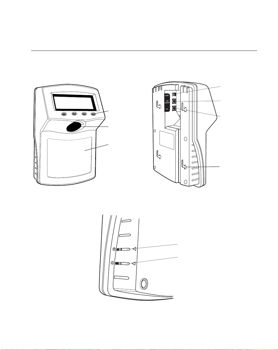
Parts of the MK1000
About Your MK1000
Front View
Function
Buttons (4)
Scan Window
Label Cover
Lower Right Side
Back View
Power Port
Com/Scanner
Port
LAN (Local Area
Network) Port
Mounting
brackets (4)
Reset Button (R)
Contrast Control (C)
Figure 1-1. Parts of the MK1000
1-3
Page 22

MK1000 MicroKiosk Product Reference Guide
Features of the MK1000
Buttons and Controls
Programmable Function Buttons
The MK1000 has four programmable function buttons (shown in Figure 1-1 on page 1-3).
These buttons can be programmed to allow the user to perform various tasks such as
navigating through an application and making decisions when prompted.
Note:For details on how to navigate MK1000 screens, see Navigating the
MK1000 Configuration Menu on page 3-19.
For details on how to enter alphanumeric values while in the
MK1000 Configuration menu, see Entering Alphanumeric Values on
page 3-21.
Reset Button
The Reset button (shown in Figure 1-1 on page 1-3) can be used to reset the system. The
Reset button is located on the lower right-hand side of the unit and marked with
paper clip to push the switch.
. Use a
Contrast Control Button
The display Contrast Control button is located below the Reset button (shown in Figure 1-
1 on page 1-3) and marked with
adjustments, if required.
1-4
. Use the tip of a small screwdriver to make contrast
Page 23
About Your MK1000
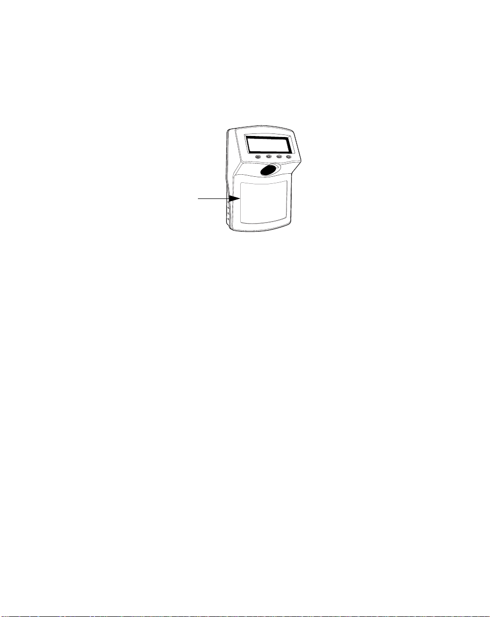
Label/Message Window
You can display labels and messages on the front of the MK1000.
To remove the plastic label cover, press from one side to bow the label cover, then lift off.
Press here.
Figure 1-2. Removing the Label Cover
To install the plastic label cover:
1. Insert the tabs of one end of the label cover into the slots on the front of the
MK1000.
2. Bow the plastic cover and insert the tabs of the other side of the label cover into the
slots on the other end of the MK1000.
1-5
Page 24

MK1000 MicroKiosk Product Reference Guide
Bar Code Scanning
The MK1000 automatically decodes a bar code presented in its field of view. It can decode
all standard 1-dimensional bar codes plus PDF, micro-PDF, and composite bar codes.
Scanning Modes
The MK1000 can operate in a number of different scanning modes. Three of the most
commonly used modes are described in Table 1-1 below.
Table 1-1. Common Scan Modes
Scan Mode Description Scan Pattern
Cyclone
Omnidirectional
1D Scan Pattern
(factory default)
“Always Raster”
Scan Pattern
This is a highly
efficient scan pattern
which decodes 1D and
EAN/UCC reduced
space symbologies in
any orientation
Note: While in this
mode, the MK1000
does not decode 2D
bar codes like PDF.
Directly opens the
laser to a full sized
raster pattern.
Decodes 1D, PDF417, RSS, and
Composite Codes.
Smart Raster
Scan Pattern
1-6
Creates a single scan
line which opens
vertically for PDF-417
symbols using the
Smart Raster feature.
This feature
autodetects the type of
bar code being
scanned and adjusts
its pattern accordingly .
This provides optimal
performance on 1D,
PDF-417, EAN/UCC,
RSS and Composite
Codes.
Page 25

About Your MK1000
Changing Scanning Modes
You can change the scanning mode using any of the following methods.
• Modify the “scan mode” setting via the MK1000’s Configuration menu.
• Send a host transmitted SSI (Simple Serial Interface) command, specifying which
scan pattern/scanning mode the MK1000 should use. For more information on this,
see Scan Engine Commands on page 5-14.
• Scan a programming bar code (refer to Appendix C, Scanning Mode Programming
Bar Codes). Any changes made by scanning a programming bar code are in effect
until the unit is powered off. At the unit’s next power up, the scanner returns to its
default scan mode setting.
Scanning Guidelines
When scanning a bar code:
• Keep the scan pattern parallel to the bar code’s rows.
• Hold the bar coded item as still as possible.
• Hold the bar code at an angle which does not cause specular reflection (see
Specular Reflection on page 1-10).
• Hold the bar coded item close for small bar codes, and farther away for large bar
codes.
1-7
Page 26
MK1000 MicroKiosk Product Reference Guide
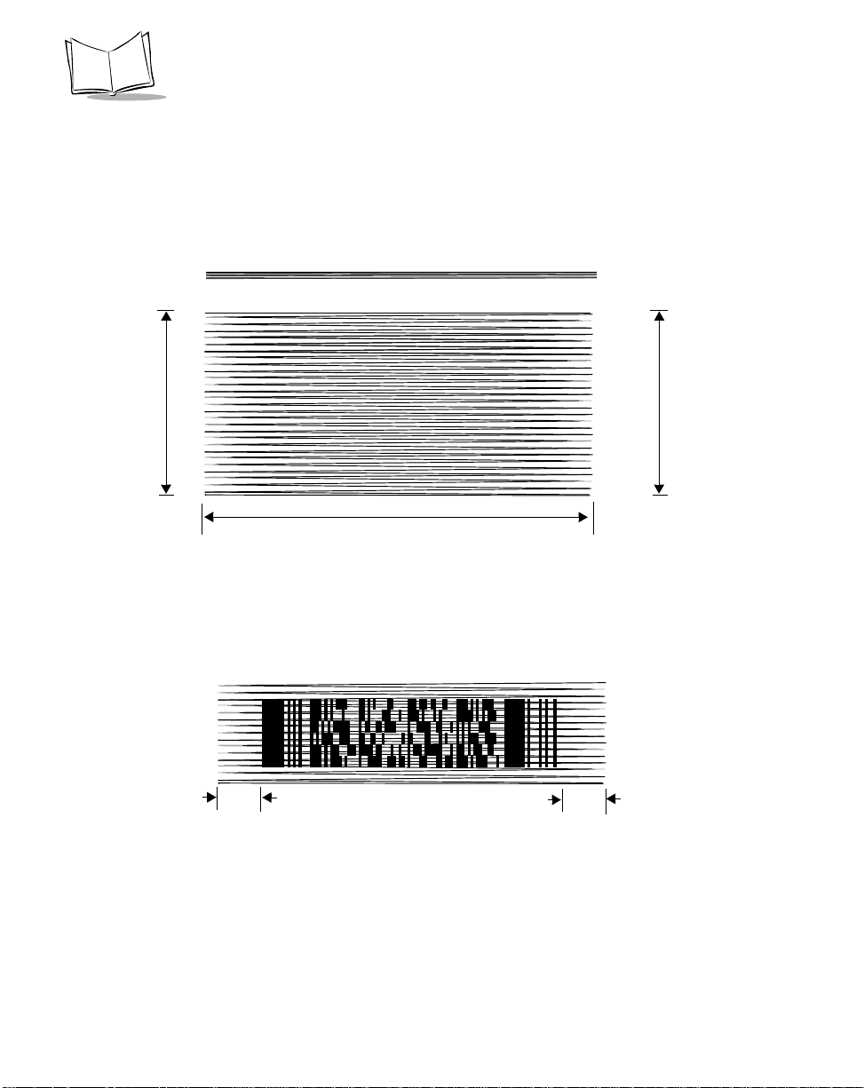
Smart Raster
In Smart Raster operation, a trigger pull causes a single scan line pattern to appear. If the
target is a 1-D bar code, the scanner decodes the symbol. If the target bar code is a 2-D
bar code, the scanning patterns open up to a full, optimized raster pattern as soon as the
scanner is properly aligned over the bar code.
Single Scan Line Pattern
Open Raster Pattern
Y-Axis
Horizontal Displacement (X - Axis)
Y-Axis
Figure 1-3. Smart Raster Scanning Pattern
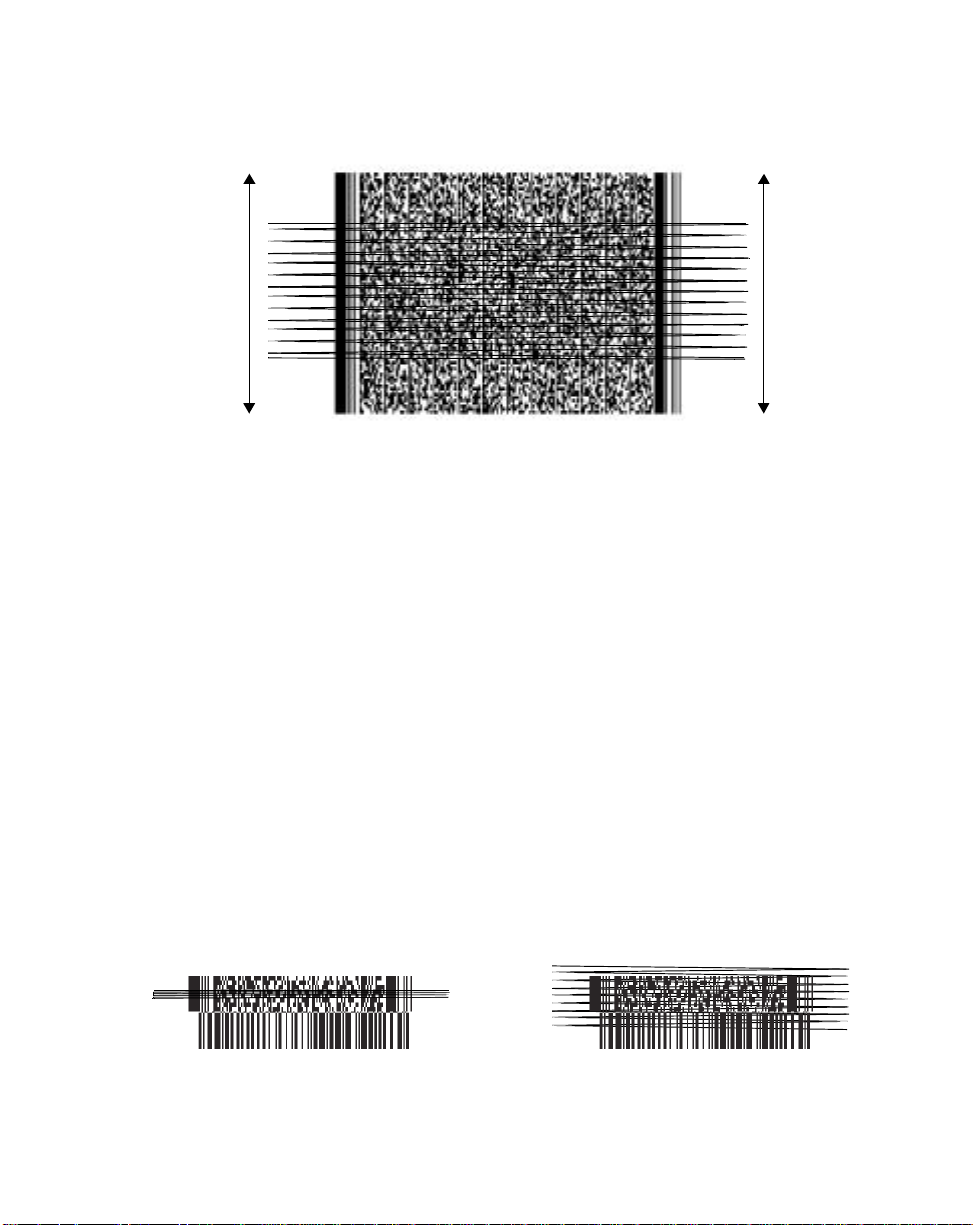
• When using the raster pattern, if the pattern does not cover the top and bottom of
a 2D symbol, pull the scanner back until it does. Make sure the scan pattern
extends at least three quarters of an inch beyond the edge s of the bar co de.
3/4”
3/4”
Figure 1-4. Raster Pattern Expanded Over PDF-417 Symbol
• If the vertical scan pattern is not high enough to cover a “tall” PDF-417 symbol,
move the bar code slowly down toward the bottom of the symbol, keeping the beam
horizontal to the rows, and then slowly back upward to the top. Alternatively, move
the bar code further away from the scanner until the scan pattern covers a larger
portion of the bar code in the vertical direction.
1-8
Page 27
About Your MK1000
Figure 1-5. Moving Scan Pattern Upward and Downward on “Tall” PDF Symbol
• The scan beam does not have to be perfectly parallel with the top and bottom of
the symbol (up to a 4
o
tilt is permitted).
• Be sure the symbol is in good condition.
Scanning Composite (2D) Bar Codes
Composite Code is a combination of a 1D symbol (RSS, UPC/EAN or UPC/EAN-128) and
a 2D symbol (CC-A, CC-B or CC-C).
When scanning a bar code:
• Keep the scan pattern parallel to the 2D symbol’s rows.
• Hold the bar code as still as possible.
• Hold the bar coded item at an angle which does not cause specular reflection (see
Specular Reflection on page 1-10).
• Hold the scanner close for small bar codes, and farther away for large bar codes.
• When using the single scan line pattern, aim the scan line at the middle of the 2D
portion. The scan pattern will open up to an optimized raster pattern and decode
both the 2D and 1D portion of the Composite Code.
Aim the single scan line at the center of
the 2D portion
Raster pattern will expand to decode
both portions
1-9
Page 28
MK1000 MicroKiosk Product Reference Guide
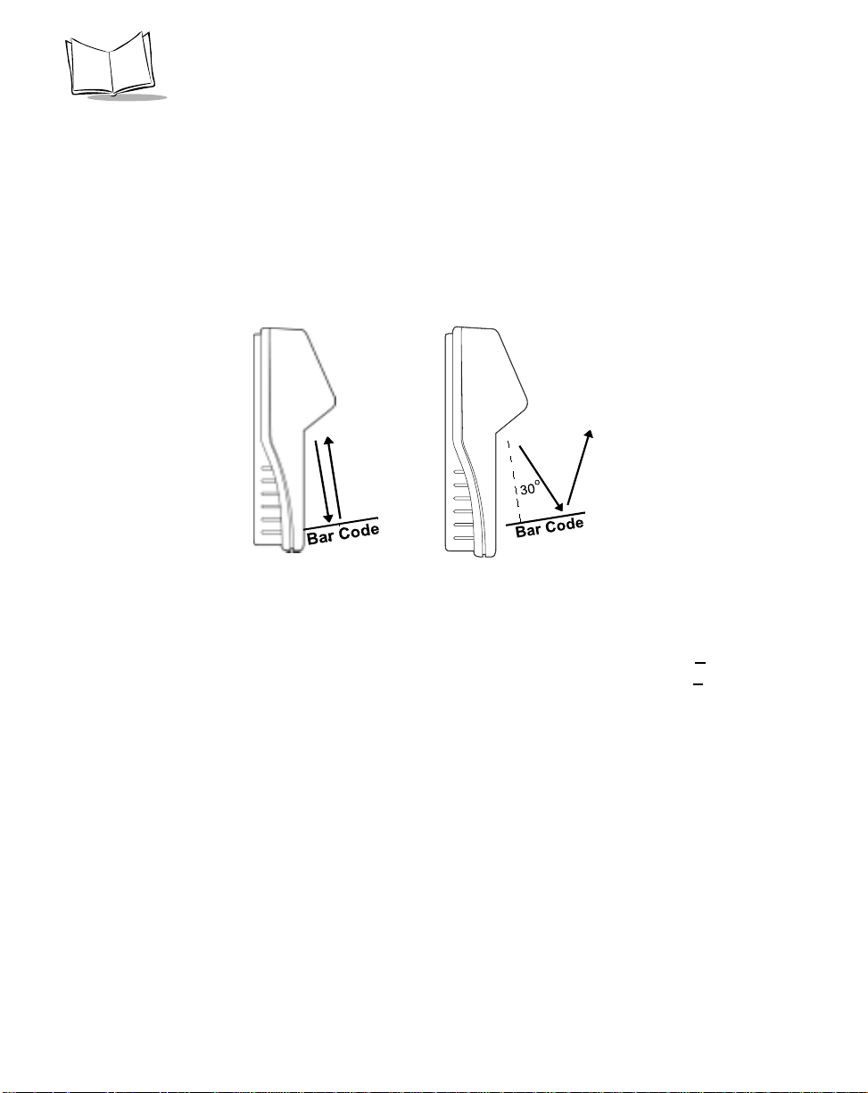
Specular Reflection
When laser beams reflect directly back into the scanner from the bar code, they can “blind”
the scanner and make decoding difficult. This phenomenon is called specular reflection.
To avoid this, scan the bar code so that the beam does not bounce directly back. But don’t
scan at too oblique an angle; the scanner needs to collect scattered reflections from the
scan to make a su cce ss ful d ecod e. P ra ct ice qu ic kl y sho w s what t ole ra nc es to w ork w i thi n.
Side Views
Specular reflection.
Reflected beam is within
specular dead zone and
prevents decode.
Tilt Bar Code At Slight Angle (Up to 30°)
No specular reflection.
Decode can occur.
Figure 1-6. Avoiding Specular Reflection
When scanning a 1D bar code, there is only a small specular dead zone to avoid (+
the direct laser beam). The specular dead zone is larger for scanning PDF-417 (+
2o from
9o from
the direct laser beam). However, the scanner is not effective if its beams hit the bar code’s
surface at an angle greater than 30
o
from the normal to that surface.
Using the Display (LCD)
The MK1000 has a back lit 240 x 64 pixel Liquid Crystal Display (LCD). The display’s colors
are white on blue. The MK1000’s display can handle both text and graphics. The LCD’s
contrast is adjustable.
Memory
Flash Memory
The MK1000 system contains 1MB of Flash Memory. This non-volatile Flash Memory is
responsible for storing the system firmware.
1-10
Page 29

About Your MK1000
Static Random Access Memory (SRAM)
The system contains 1MB of SRAM. The SRAM is used for storage of system parameters,
user programs and data, and for use by the system as a whole during normal program
executions. Items such as bitmaps can also be stored here and easily retrieved for later
use.
External Ports
The MK1000 is equipped with three external ports located at the rear of the unit (see Figure
1-1 on page 1-3). The external ports are:
•Power
• Com/Scanner
•LAN.
The ports are located in a recessed area to allow for flush mounting of the MK1000 against
a flat surface.
Power Port
The MK1000 can be powered by either an external power supply plugged into an AC outlet
or by Power-over-Ethernet. If an external power supply is used, it plugs into the power port
on the rear of the MK1000 via a 2.0mm barrel jack. The center pin of the jack is positive
and the outer tab is ground.
The universal power supply provided with your MK1000 is compatible with the following
power systems:
• 120V 60Hz (North America)
• 230V 50Hz (International excluding Japan)
• 100V 50/60Hz (Japan).
Com/Scanner Port
The connection to the Com/Scanner port is provided through an RJ-45 jack (10 conductor).
This port has dual functionality and can be used for Serial communication with a host,
connection of an external device like a decoded scanner, or connection of an undecoded
external scanner. It is important to confirm your cable’s pin-out before attaching a cable. For
cable pin-outs, see RS-232 Connectors - Com/Scanner Port on page 2-16.
1-11
Page 30

MK1000 MicroKiosk Product Reference Guide
LAN (Local Area Network) Port
The connection to this port is provided through an RJ-45 jack.
The LAN port supports the following network topologies listed and described below.
• Ethernet (10Base-T)
• Power via AC Outlet
• Power via Power-over-Ethernet
• RS-485 (Serial/Cable)
Wired Ethernet: Power via AC Outlet
The LAN port can be used for an Ethernet data connection., either a 10-conductor RJ-45
plug or 8-conductor RJ-45 plug can be used. With this Ethernet installation the MK1000
receives power via the power supply plugged into an AC outlet.
Wired Ethernet: Power via Power-over-Ethernet
The MK1000 supports Power-over-Ethernet (Symbol Technologies' Bias-T functionality).
When an Ethernet (10Base-T) cable is connected to the LAN port, in addition to being the
conduit for data exchange, it can also be used as a conduit to provide power to the MK1000.
RS-485
RS-485 is sometimes termed the Multidrop LAN since it can connect several devices in a
LAN network environment. These devices are all connected to a single pair wire (i.e.,
transmit and receive share the same two wires).
When the LAN port is used as an RS-485 connection, only a 10-conductor RJ-45 plug can
be used.
1-12
Page 31

Chapter 2
Setup and Installation: Mechanical
Overview
This chapter describe s the hardware setup and installation of the MK1000.
Topics covered in this chapter include mounting, providing power, and connecting
communication cables (if required) for the following four MK1000 communication
interfaces:
• Wireless Ethernet (2Mb or 11Mb RF)
• Power via AC outlet
• Power via Power-over-Ethernet
• Wired Ethernet (10Base-T cable)
• Power via AC outlet
• Power via Power-over-Ethernet
• Wired RS-485 (Serial cable)
• Wired RS-232 (Serial cable).
Note:After completing the mechanical installation of the MK1000,
refer to Chapter 3, Setup and Installation: Communication to
establish communication with the host.
2-1
Page 32

MK1000 MicroKiosk Product Reference Guide
Wired Ethernet Setup
The MK1000 can communicate with a host via a wired Ethernet connection (10Base-T
cable).
When communicating in this manner the MK1000 can be powered either using the
MK1000’s power supply connected to an AC outlet, or by receiving Power-over-Ethernet
through the Ethernet cable.
Wired Ethernet: Power via AC Outlet
With this installation option, the MK1000 communicates to the host via a 10Base-T Ethernet
cable and receives power via a power supply plugged into an AC outlet.
To install the MK1000, follow the instructions below.
1. Provide power to the MK1000 using its power supply .
• Insert the round barrel connector at the end of the power supply cable into the
MK1000’s Power port. (See Figure 1-1 on page 1-3 for port locations.)
• Plug the power supply into a wall outlet.
2. Attach the Ethernet cable.
• Connect the Ethernet cable to the LAN port on the MK1000. (See Figure 1-1 on
page 1-3 for port locations.) Ensure the Ethernet cable is terminated according
to the Ethernet Pin-Outs: Obtaining Power via AC Power Supply described in
Table 2-1 and Table 2-2.
• Plug the other end of the Ethernet cable into the host system’s LAN port.
3. To mount the MK1000, see Mounting the MK1000 on page 2-11.
After completing the mechanical installation of the MK1000, refer to Chapter 3, Setup and
Installation: Communication to establish communication with the host.
2-2
Page 33

Setup and Installation: Mechanical
Wired Ethernet: Power via Power-over-Ethernet
With this installation option, in addition to the MK1000 communicating to the host via a
10Base-T Ethernet cable, the MK1000 also simultaneously receives its power via the same
Ethernet cable.
Note:Power-over-Ethernet should NOT be used in conjunction with an
external power supply connected to the power port on the MK1000
otherwise damage can occur to the MK1000 and/or network.
To install the MK1000, follow the instructions below.
1. Attach the Ethernet cable.
• Connect the Ethernet cable to the LAN port on the MK1000. (See Figure 1-1 on
page 1-3 for port locations.) Ensure the Ethernet cable is terminated according
to the Ethernet Pin-Outs: Obtaining Power via Power-over-Ethernet described
in Table 2-3 and Table 2-4.
• Plug the other end of the Ethernet cable into the Bias-T (Power-over-Ethernet)
module.
2. Connect a patch cable from the Bias-T (Power-over-Ethernet) module to your host
system’s LAN port.
3. To mount the MK1000, see Mounting the MK1000 on page 2-11.
After completing the mechanical installation of the MK1000, refer to Chapter 3, Setup and
Installation: Communication to establish communication with the host.
2-3
Page 34

MK1000 MicroKiosk Product Reference Guide
Wireless Ethernet Setup
The MK1000 can communicate with a host via a wireless (RF) Ethernet connection.
When communicating in this manner the MK1000 can be powered either using the
MK1000’s power supply connected to an AC outlet, or by receiving Power-over-Ethernet
via cable.
Wireless Ethernet: Pow e r via AC Outlet
With this installation option, the MK1000 communicates to the host via a wireless (RF)
connection and receives power via a power supply plugged into an AC outlet.
To install the MK1000, follow the instructions below.
1. Provide power to the MK1000 using its power supply .
• Insert the round barrel connector at the end of the power supply cable into the
MK1000’s Power port. (See Figure 1-1 on page 1-3 for port locations.)
• Plug the power supply into a wall outlet.
2. To mount the MK1000, see Mounting the MK1000 on page 2-11.
After completing the mechanical installation of the MK1000, refer to Chapter 3, Setup and
Installation: Communication to establish communication with the host.
2-4
Page 35

Setup and Installation: Mechanical
Wireless Ethernet: Power via Power-over-Ethernet
With this installation option, the MK1000 communicates to the host via a wireless (RF)
connection and receives power via an Ethernet cable.
Note:This Ethernet cable does NOT provide data to the MK1000.
To install the MK1000, follow the instructions below.
1. Attach the Ethernet cable to provide power to the MK1000.
• Connect the Ethernet cable to the LAN port on the MK1000. (See Figure 1-1 on
page 1-3 for port locations.) Ensure the Ethernet cable is terminated according
to the Ethernet Pin-Outs: Obtaining Power via Power-over-Ethernet described
in Table 2-3 and Table 2-4.
• Plug the other end of the Ethernet cable in the hub.
2. Connect a patch cable from the Bias-T (Power-over-Ethernet) module to your host
system’s LAN port.
3. To mount the MK1000, see Mounting the MK1000 on page 2-11.
After completing the mechanical installation of the MK1000, refer to Chapter 3, Setup and
Installation: Communication to establish communication with the host.
2-5
Page 36

MK1000 MicroKiosk Product Reference Guide
Wired RS-485 Setup
The MK1000 can communicate with a host via a wired RS-485 Serial connection while
receiving power via a power supply plugged into an AC outlet.
For MK1000 devices installed where pre-existing PCK 9100 wiring exists, an RS-485 pinout converter can be used. This pin-out converter maps the PCK 9100 signals into the
required MK1000 pin-out and attaches to the existing PCK 9100 wiring, and then into the
MK1000.
RS-485 is a two-wire differential signal: RS-485 signal and RS-485 inverted signal. See
Figure 2-2 on page 2-8 for an illustration of the two-wire differential signal.
When installing an RS-485 configuration, ensure each MK1000 is connected directly to the
RS-485 bus (see Figure 2-1).
Wire nuts or connector
block may be used
1 2 3 4
Figure 2-1. Connector Block
The cable required for an RS-485 installation should meet or exceed the following
specifications:
• 1 twisted pair 26 AWG (7/34) tinned copper
• twisted pair foil wrapped - 100% coverage
• nominal impedance 120 ohms
• capacitance between twisted pair 10-25 pf per foot
• capacitance between conductors & shield 20-35 pf per foot
• DC resistance of each conductor 45 ohms per 1000 feet
• DC resistance of shield 10 ohms per 1000 feet.
If your host does not support RS-485 and you wish to use RS-485 as your communication
interface, an RS-232 to RS-485 conversion box is required. The conversion box must be
sourced locally and is not available from Symbol Technologies.
2-6
Page 37

Setup and Installation: Mechanical
To install the MK1000 with a host that does not support RS-485, follow the instructions
below.
1. Provide power to the MK1000 using its power supply .
• Insert the round barrel connector at the end of the power supply cable into the
MK1000’s Power port. (See Figure 1-1 on page 1-3 for port locations.)
• Plug the power supply into a wall outlet.
2. Connect the conversion box to the host using an RS-232 cable.
3. Attach the RS-485 Serial cable.
• Connect the RS-485 Serial cable to the LAN port on the MK1000. (See Figure
1-1 on page 1-3 for port locations.) Ensure the Serial cable is terminated
according to the RS-485 Connectors - LAN Port described in Table 2-5.
• Plug the other end of the RS-485 Serial cable into the converter box.
4. To mount the MK1000, see Mounting the MK1000 on page 2-11.
After completing the mechanical installation of the MK1000, refer to Chapter 3, Setup and
Installation: Communication to establish communication with the host.
2-7
Page 38

2-8
4000 Ft. Maximum
RS-232/RS-485
Conversion Box
RS-232
Figure 2-2. RS-485 Two-Wire Serial Network
100Ω
1/2 W
GWG
GWG Green wire g round or power
system ground
Circuit ground or circuit
common
100Ω
1/2 W
Termination Resistors at Both Ends
Rt
GWG
100Ω
1 2 3 4
100Ω 100Ω
GWG
1 2 3 4
100Ω
Recommended RS-485 Two-Wire Multidrop NetWork
Rt
100Ω
1/2 W
MK1000 MicroKiosk Product Reference Guide
1 2 3 4
GW
100Ω
1/2 W
Rt 120
Ω
1/2W
Page 39

Setup and Installation: Mechanical
Wired RS-232 Setup
The MK1000 can communicate with a host via a Serial cable connected to the Com/
Scanner port while receiving power via a power supply plugged into and AC outlet.
To install the MK1000, follow the instructions below.
1. Provide power to the MK1000 using its power supply .
• Insert the round barrel connector at the end of the power supply cable into the
MK1000’s Power port. (See Figure 1-1 on page 1-3 for port locations.)
• Plug the power supply into a wall outlet.
2. Attach the RS-232 Serial cable.
• Connect the RS-232 Serial cable to the Com/Scanner port on the MK1000.
(See Figure 1-1 on page 1-3 for port locations.) Ensure the Serial cable is
terminated according to the Serial/RS-232 Communication pin-outs described
in Table 2-6.
• Plug the other end of the Serial cable into the host.
3. To mount the MK1000, see Mounting the MK1000 on page 2-11.
After completing the mechanical installation of the MK1000, refer to Chapter 3, Setup and
Installation: Communication to establish communication with the host.
2-9
Page 40

MK1000 MicroKiosk Product Reference Guide
Connecting an Auxiliary Device to the Com/Scanner Port
If the Com/Scanner port is not being used for communication with the host, an external
device, such as a scanner (decoded or undecoded), can be attached to the Com/Scanner
port. (See Figure 1-1 on page 1-3 for port locations.) The auxiliary device can pull power
from the MK1000.
To connect an external device, follow the instructions below.
1. Attach the auxiliary device’s cable to the Com/Scanner port on the MK1000. (See
Figure 1-1 on page 1-3 for port locations.) Ensure the auxiliary device’s cable is
terminated properly.
•For Serial/RS-232 Communication pin-outs see Table 2-6.
• For Undecoded Wand/Wand Emulation Communication pin-out s see Table 2-7.
2. Plug the other end of the cable into the auxiliary device.
3. To mount the MK1000, see Mounting the MK1000 on page 2-11.
After completing the mechanical installation of the MK1000, refer to Chapter 3, Setup and
Installation: Communication to establish communication with the host.
2-10
Page 41

Setup and Installation: Mechanical
Mounting the MK1000
The MK1000 can be mounted on a wall, pole or counter top. Separately sold mounting
accessories are listed below.
• Wall Mount Kit
• Pole Mount Kit
• Counter Top Stand
The MK1000 can also be mounted without the accessories listed above. To mount the
MK1000 on a wall without using the wall mount kit, follow the instructions below.
1. Determine the MK1000 mounting location.
2. Using a pencil, mark the mounting screw location. Refer to the mounting template
provided in the MK1000 Quick Reference Guide (p/n 72-52968-xx) included with
every MK1000. The screws must be 5 inches (12.7 cm) apart, left to right: and, 6
inches (15.3 cm) apart, top to bottom.
(15.3 cm)
6”
5”
(12.7 cm)
Figure 2-3. Mounting Dimensions
There must be a clearance of at least 9/16 of an inch (14.3mm) between the center of the
right side mount holes and nearest object.
2-11
Page 42

MK1000 MicroKiosk Product Reference Guide
1. Install the mounting screws in the markings on the wall, leaving room for the mounting
holes on the back of the MK1000 to slide onto. Ensure the screws are securely anchored to the wall.
2. Place the MK1000 on the wall, aligning the notches on the back of the unit with the
mounting screws. Ensure all cables lie neatly in the channel provided on the back of
the unit.
3. Slide the MK1000 to the left and down to secure in place.
Figure 2-4. Mounting Directions
2-12
Page 43

Setup and Installation: Mechanical
Cable Pin-Outs
Table 2-1 through Table 2-7 describe the CABLE termination required for attaching an
external cable to the MK1000.
8-Pin
10-Pin
Pin 1 Pin 8
Pin 1
Pin 10
Figure 2-5. 8-Pin and 10-Pin Connectors
Ethernet Connectors - LAN Port
Ethernet Pin-Outs: Obtaining Power via AC Power Supply
Table 2-1. Ethernet 10Base-T Cable: 8-Pin
Pin Description
Pin 1 TXD (+)
Pin 2 TXD (-)
Pin 3 RXD (+)
Pin 6 RXD (-)
Pin 7 GND
Pin 8 GND
T able 2-2. Ethernet 10Base-T Cable: 10-Pin
Pin Description
Pin 2 TXD (+)
Pin 3 TXD (-)
2-13
Page 44

MK1000 MicroKiosk Product Reference Guide
Table 2-2. Ethernet 10Base-T Cable: 10-Pin (Continued)
Pin Description
Pin 4 RXD (+)
Pin 7 RXD (-)
Pin 8 GND
Pin 9 GND
Ethernet Pin-Outs: Obtaining Power via Power-over-Ethernet
Power-over-Ethernet pin-out connectors allow ethernet signals and power supply voltage
to be supplied to the MK1000 through a single Ethernet cable.
If power to the MK1000 is being provided via Power-over-Ethernet, do NOT plug the power
supply into the MK1000 as well.
T able 2-3. Power-over-Ethernet Cable: 8-Pin
Pin Description
Pin 1 TXD (+)
Pin 2 TXD (-)
2-14
Pin 3 RXD (+)
Pin 4 Bias-T (+)
Pin 5 Bias-T (-)
Pin 6 RXD (-)
Pin 7 GND
Pin 8 GND
Page 45

Table 2-4. Power-over-Ethernet Cable: 10-Pin
Pin Description
Pin 2 TXD (+)
Pin 3 TXD (-)
Pin 4 RXD (+)
Pin 5 Bias-T (+)
Pin 6 Bias-T (+)
Pin 7 RXD (-)
Pin 8 GND
Pin 9 GND
RS-485 Connectors - LAN Port
Table 2-5. RS-485 Cable: 10-Pin
Setup and Installation: Mechanical
Pin Description
Pin 1 RS-485 (+)
Pin 8 GND
Pin 10 *RS-485 (-)
* Inverted Signal
2-15
Page 46

MK1000 MicroKiosk Product Reference Guide
RS-232 Connectors - Com/Scanner Port
Serial/RS-232 Communication
This cable pin-out can be used for both Serial communication from the host to the MK1000
and/or communication between an external hand held decoded scanner and the MK1000.
Table 2-6. RS-232 Cable: 10-Pin
Pin Description
Pin 1 +5V @ 500mA
maximum (output)
Pin 3 RXD (input)
Pin 5 RTS (output)
Pin 6 Ground
Pin 7 CTS (input)
Pin 9 TXD (output)
Undecoded Wand/Wand Emulation Communication
Table 2-7. Undecoded Auxiliary Device Cable: 10-Pin
Pin Description
Pin 1 Power +5V@200mA
maximum
Pin 2 Laser On
Pin 4 *DBP
Pin 6 GND
Pin 8 Trigger
* Digital Bar Code Pattern
2-16
Page 47

Setup and Installation: Mechanical
MK1000 LAN Port Pin-Outs
Table 2-8 describes the MK1000’s pin-outs for its LAN port and is given for general starting
information only. T o generate a cable to attach to the MK1000, see Cable Pin-Out s on page
2-13.
T a ble 2-8. MK1000 LAN Port: RJ-45 10-Pin
Pin Description
Pin 1 RS-485 TXD/RXD (+)
Pin 2 10BaseT TXD (+)
Pin 3 10BaseT TXD (-)
Pin 4 10BaseT RX D (+)
Pin 5 BIAS-T (+)
Pin 6 BIAS-T (+)
Pin 7 10BaseT RXD (-)
Pin 8 GND
Pin 9 GND
Pin 10 RS-485 TXD/RXD (-)
2-17
Page 48

MK1000 MicroKiosk Product Reference Guide
2-18
Page 49

Chapter 3
Setup and Installation: Communication
Overview
This chapter describes the steps required to establish communication between the MK1000
and a host.
Note:The host must be able to support either the RS-232 or Ethernet
communication interface. Common host operating systems that
support these interfaces include Windows, Unix, DOS, and IBM
468x/469x.
Topics covered in this chapter include:
• Communication protocol (PCK emulation) overview
• Selecting a communication interface
• Configuring for host communication via the MK1000 Configuration menu
• Configuring for host communication via the PCK Configuration menu
• Configuring for host communication via a Telnet client.
Before communications with the host is established, you must determine which
communication interface to use.
3-1
Page 50

MK1000 MicroKiosk Product Reference Guide
Communication Protocol Overview
The MK1000 is shipped with the PCK emulation communication protocol on-board.
The Symbol PCK emulation application* is a PCK9100/9140 emulator for the Symbol
MK1000. The Symbol PCK emulation application uses a proprietary command set
developed by Symbol Technologies for use with its Kiosk Scanning Solutions. The PCK
emulation application allows the MK1000 to behave like a Symbol PCK9100/9140 and
interact with PCK9100/9140 compatible applications on the host. For more information on
the PCK emulation application see Chapter 5, PCK Emulation.
Note:*The MK1000’s PCK emulation application is not compatible with
pre-existing PCK9142/9144/9130 applications.
Communication Interface Overview
Before establishing communications with the host you must determine which
communication interface to use. Your MK1000 may support up to four communication
interfaces. The four types of interfaces are listed in Table 3-1.
The number and type of communication interfaces your unit has is specified in its model
number. For a list of MK1000 model numbers and their supported onboard communication
interfaces see the Appendix F, Troubleshooting.
Table 3-1. Communication Interfaces Versus Communication Protocols
Communication Protocol
Communication Interface
Ethernet - Wireless (2 Mbps or 11 Mbps RF) x
Ethernet - Wired (10Base-T Cable) x
RS-485 (Wired Serial) x
RS-232 (Wired Serial) x
3-2
PCK Emulation
Page 51

Setup and Installation: Communication
Configuring the MK1000 for Host Communication
Now that the communication interface has been selected, you are ready to configure the
MK1000 for communication with your host. T able 3-2 shows the different methods available
for configuring the MK1000.
Table 3-2. Methods of Configuring the MK1000
Remote Local
Bar codes
and
Computer Bar codes
- PCK Configuration Menu X - See Notes 1 and 4
- MK1000 Configuration Menu X - See Notes 2 and 5
- Telnet Session X - See No tes 2 and 3
Notes:
1. From the PCK Configuration menu the following parameters cannot be configured:
the RF Settings, ESS ID, Encryption, Key ID, and Key Management. These
parameters can be configured from the MK1000 Configuration menu and/or a
Telnet Session.
2. From the MK1000 Configuration menu and/or a Telnet session the following PCK
emulation parameters cannot be configured: the PCK communication interface
(Change/Select Host Type), software handshaking, and RS-485 Net ID. These
parameters can be configured from the PCK Configuration menu.
3. T elnet sessions require an Ethernet connection between the host and the MK1000.
4. PCK Configuration programming bar codes are located in Appendix B, PCK
Configuration Programming Bar Codes.
5. MK1000 Configuration menu programming bar codes are available in Appendix A,
Configuration Menu Programming Bar Codes.
4 Buttons Comments
3-3
Page 52

MK1000 MicroKiosk Product Reference Guide
Configuring via the PCK Configuration Menu
Overview
The MK1000 can be configured for operation with PCK based applications using the PCK
Configuration menu. The PCK Configuration menu can be accessed locally by scanning
programming barcodes, which are available in Appendix B, PCK Configuration
Programming Bar Codes.
From the PCK Configuration menu all MK1000 parameters can be accessed except the RF
Settings, ESS ID, Encryption, Key ID, and Key Management. These parameters can only
be accessed from the MK1000 Configuration menu and/or a T elnet session. For information
on alternate methods of configuring the MK1000, see page 3-3.
3-4
Page 53

Setup and Installation: Communication
MAP: PCK Configuration Menu
The following map can be used to assist in the navigation of the PCK application.
Change Interface
1.
Change Host Type
2.
3.
Change Host Config:
-
TCP/IP
or
UDP/IP
-
RS-232
-
RS-485
4.
Edit Aux Port Params
Wired Ethernet (10BASE-T cable)
Wireless Network (802.11 / 802.11b RF)
TCP/IP
UDP/IP
RS-232
RS-485
Edit
Software
Handshaking
Baud
Data Bits
Stop Bits
Parity
Flow Control
Baud
Data Bits
Stop Bits
Parity
Flow Control
Net ID
DTR/DSR
Flow Control
ACK/NAK with ENQ
DHCP Enabled
IP Address
Subnet Mask
Gateway
Go to DNS Screen
Go to page 2
None
Xon/Xoff
Baud
Data Bits
Stop Bits
Parity
None
ACK/NAK
ENQ
RAW
1
2
None
Xon/Xoff
DTR/DSR
1
2
Edit DNS IP #1
Edit DNS IP #2
Edit DNS IP #3
Host IP
Host Port
1200
7
8
9
None
Odd
Even
7
8
9
None
Odd
Even
7
8
1
9
2
None
Odd
Even
2400
4800
9600
14400
19200
1200
2400
4800
9600
14400
19200
1200
2400
4800
9600
14400
19200
None
Xon/Xoff
DTR/DSR
Figure 3-1. Navigating the PCK Configuration Menus/Scr eens
3-5
Page 54

MK1000 MicroKiosk Product Reference Guide
Entering, Navigating & Saving Changes
Entering the PCK Configuration Menu
To access the PCK Configuration menu scan the Enter PCK Configuration Menu
programming bar code, available in Appendix B, PCK Configuration Programming Bar
Codes.
When the bar code is scanned, the following menu displays:
3&.&RQILJXUDWLRQ
&XUUHQW+RVW7&3,3%$6(7
&KDQJH,QWHUIDFH
&KDQJH+RVW7\SH
&KDQJH+RVW&RQILJ
(GLW$X[3RUW3DUDPV
6FDQ
WR6HOHFW,WHP
Figure 3-2. PCK Configuration Menu
Navigating the Main Menu
To navigate the main menu, scan the numeric programming bar code in Appendix B, PCK
Configuration Programming Bar Codes that corresponds to the menu option (parameter)
you wish to review/change. For example, if you wish to change the host type, you can
access the Select Host Type screen by scanning the “2” bar code at the
menu.
PCK Configuration
Saving Changes
After you have navigated through the necessary screens and made your desired changes,
you can save the changes by scanning the Save & Exit bar code on page B-4.
Escaping a Screen Without Saving Changes
If you have accidentally entered a screen and wish to exit it WITHOUT making ANY
changes, scan the Cancel bar code on page B-5.
3-6
Page 55

Setup and Installation: Communication
Exiting the PCK Configuration Menu
When all desired changes are made, scan the Exit and Save Changes bar co de on page
B-3 to exit PCK emulation configuration.
Selecting an Option (Parameter) from a List of Options
To select an parameter from a list, scan the numeric programming bar code in Appendix B,
PCK Configuration Programming Bar Codes that corresponds to the parameter you wish to
select.
For example, to change the communication interface to wired Ethernet, navigate the main
menu and make your communication interface selection as follows:
1. Scan the Enter PCK Configuration Menu bar code to access the PCK
Configuration menu.
2. Scan the number “1” bar code to access the Select Interface Type screen.
3. Scan the number “1” bar code to choose Wired Ethernet (10BaseT) as yo ur
communication interface.
4. When the number “1” bar code is scanned and Wired Ethernet (10BaseT) is
selected, you are returned to the PCK Configuration menu.
5. Continue with additional changes by scanning the appropriate numeric bar code to
access another screen, or to initiate operation of the MK1000 in PCK emulation
mode, scan the Save & Exit bar code.
Note:Scan the Cancel bar code to exit WITHOUT saving ANY of your
changes.
Entering Field Data (Numeric Values)
Data fields, such as IP Address, require the user to enter a combination of numeric values.
On the appropriate screen, enter the numeric values by scanning the bar codes that
correspond to the data you wish to enter.
For example, to enter a numeric value such as an IP Address:
1. Scan the Enter PCK Configuration Menu bar code to access the PCK
Configuration menu.
2. Ensure the communication interface is set to Ethernet. Your “current
(communication interface) host setting” is displayed on the second line of the PCK
Configuration menu.
3-7
Page 56

MK1000 MicroKiosk Product Reference Guide
• If your current setting is Ethernet (wired or wireless and TCP/IP or UDP/IP), no
change is necessary.
• If your current setting is not Ethernet, scan the “1” bar code to change the
interface and scan the “1” bar code again to select Ethernet.
3. Once your communication interface is confirmed, check and change the MK1000’s
IP address by scanning the number “3” bar code (Change Host Config) at the PCK
Configuration menu to access the
4. Scan the number “1” bar code (TCP/IP) to access TCP/IP Configuration Page 1
TCP/IP Configuration Page 1.
screen.
5. Scan the number “2” bar code (IP Address) to access the IP address data field.
This screen displays the current IP address field (Curr IP Addr) and the new IP
address field (New IP Addr).
6. To enter a new IP address, scan the numeric bar codes that correspond to the IP
address you desire. Note that the IP address field requires you to scan three digits
for each segment in the address for the segment separator "dots" to be applied
correctly (s ee Example: Entering an Numeric Value -- IP Address on page 3-9).
7. When you have completed scanning the IP address via numeric bar codes, scan
the Save & Exit bar code to save your changes and exit the current screen. The
MK1000 changes its IP address to the new value you entered and returns you to
the previous screen.
or
If you do not wish to change the current (IP address) setting, scan the Cancel bar
code to exit the WITHOUT saving your changes.
3-8
Page 57

Setup and Installation: Communication
Example: Entering an Numeric Value -- IP Address
To enter a new IP address of 234.239.5.16, scan the following programming bar codes in
this order:
Scan Bar Code Screen Display
22
323
4234
2 234.2
3 234.23
9 234.239
0 234.239.0
0 234.239.00
5 234.239.005
0 234.239.005.0
1 234.239.005.01
6 234.239.005.016
Save & Exit Previous screen (I/P
address changed)
Save & Exit Main menu
Save & Exit Exit main menu and
initiate operation of the
MK1000 in PCK
emulation mode.
3-9
Page 58

MK1000 MicroKiosk Product Reference Guide
PCK Configuration Menu
The main PCK Configuration menu displays when the Enter PCK Configuration Menu
programming bar code is scanned (see Figure 3-2).
Selecting an Interface Type
Change Interface - PCK Configuration Menu Option 1
To select or change the interface type that the MK1000 uses to talk to a host, choose
Change Interface at the PCK Configuration menu by scanning the "1" bar code located in
the section Numeric Bar Codes on page B-7.
The Select Interface Type screen displays.
6HOHFW,QWHUIDFH7\SH
:LUHG(WKHUQHW%DVH7
:LUHOHVV1HWZRUN
6FDQRUWR6HOHFW,WHP
Figure 3-3. Select Interface Type Screen
Scanning a "1" or "2" bar code sets the type (10BaseT or Wireless) and returns you to the
PCK Configuration menu.
3-10
Page 59

Setup and Installation: Communication
\S
Selecting a Host Type
Change Host Type- PCK Configuration Menu Option 2
To select or change the host type, choose Change Host Type at the PCK Configuration
menu by scanning the "2" bar code located in the section Numeric Bar Codes beginning on
page B-6 to display the Select Host Type screen.
6HOHFW+RVW7\SH
7&3,3
8'3,3
56
56
(GLW6RIWZDUH+DQGVKDNLQJ
6FDQIRU+RVW7
Figure 3-4. Select Host Type Screen
Scanning a "1", "2", “3”, or “4” bar code selects the corresponding host type and returns you
to the PCK Configuration menu.
H
Scan the “5” bar code to edit Software Handshaking.
3-11
Page 60

MK1000 MicroKiosk Product Reference Guide
\S
Editing Software Handshaking
Note:Software Handshaking configuration supported in PCK emulation
versions 1.06 and greater.
When you scan the “5” bar code at the Select Host Type screen, the Software Handshaking
Config screen displays .
6RIWZDUH+DQGVKDNLQJ&RQILJ
&XUUHQW+6$&.1$.
1RQH
$&.1$.
(14
$&.1$.ZLWK(14
5$:
6FDQIRU6:+67
Figure 3-5. Software Handshaking Config Screen
Scan the numeric bar code corresponding to the type of Software Handshaking desired.
Once scanned, you are returned to the Select Host Type screen.
H
Changing Host Configuration
Change Host Config- PCK Configuration Menu Option 3
To select or change the settings for a particular host type, choose Change Host Config at
the PCK Configuration
Bar Codes on page B-7.
This system displays a host configuration screen that matches the host type currently
selected. If it is inappropriate, scan the Cancel bar code to return to the main PCK
Configuration
type.
The host configuration screen displayed can be a Serial type (RS-232 or RS-485), or an
Ethernet host. If an Ethernet host, either a TCP/IP configuration or UDP/IP configuration
screen displays. Ensure this setting is correct. If not, correct it before you proceed. Both
host types (Serial and Ethernet) have two pages of parameters to set, and both are handled
similarly.
3-12
menu and scan the “2” bar code (Change Host Type) to set the correct host
menu by scanning the "3" bar code located in the section Numeric
Page 61

Setup and Installation: Communication
TCP/IP Configuration
When the TCP/IP option is scanned for TCP/IP configuration, the following screen displays:
7&3,3&RQILJXUDWLRQ3DJH
'+&3(QDEOHG1R
,3$GGUHVV
6XEQHW0DVN
*DWHZD\
*RWR'166FUHHQ
*RWR3DJH
6FDQLWHPQXPEHUWRHGLW
Figure 3-6. TCP/IP Configuration Page 1
Scan the number "6" bar code to display the second TCP/IP screen.
7&3,3&RQILJXUDWLRQ3DJH
+RVW,3
+RVW3RUW
*R%DFNWR3DJH
6FDQLWHPQXPEHUWRHGLW
Figure 3-7. TCP/IP Configuration Page 2
Scan the re quired numeri c bar co de(s) to ent er dat a in an y fie ld, as necessar y. For Host IP
addresses, you must enter three digits for each segment for "dots" to be supplied correctly.
For example, if you want to set the address 10.10.1.2, you must enter 010.010.001.002.
Remember to scan the Save & Exit bar code when you are finished, or scan Cancel to
escape WITHOUT completing the entry.
3-13
Page 62

MK1000 MicroKiosk Product Reference Guide
UDP/IP Configuration
When the UDP/IP option is scanned for UDP/IP configuration, the following screen displays
(scan the number "6" bar code to display the second UDP/IP screen):
8'3,3&RQILJXUDWLRQ3DJH
'+&3(QDEOHG1R
,3$GGUHVV
6XEQHW0DVN
*DWHZD\
*RWR'166FUHHQ
*RWR3DJH
6FDQLWHPQXPEHUWRHGLW
8&3,3&RQILJXUDWLRQ3DJH
+RVW,3
+RVW3RUW
*R%DFNWR3DJH
6FDQLWHPQXPEHUWRHGLW
Figure 3-8. UDP/IP Configuration Pages 1 & 2
Scan the re quired numeri c bar co de(s ) to ent er dat a in any fie ld, as necess ary. For Host IP
addresses, you must enter three digits for each segment for "dots" to be supplied correctly.
For example, if you want to set the address 10.10.1.2, you must enter 010.010.001.002.
Remember to scan the Save & Exit bar code when you are finished, or scan Cancel to
escape WITHOUT completing the entry.
3-14
Page 63

Setup and Installation: Communication
Auxiliary Port Parameters
Edit Aux Port Params - PCK Configuration Menu Option 4
T o select or change the auxiliary port parameters, choose Edit Aux Port Params at the PCK
Configuration menu by scanning the "4" bar code located in the section Numeric Bar Codes
beginni ng on page B-6.
The following RS-232 Configuration screen displays:
56&RQILJXUDWLRQ
%DXG
'DWD%LWV
6WRS%LWV
3DULW\(YHQ
)ORZ&QWUO1RQH
6FDQ,WHP1XPEHUWR(GLW
Figure 3-9. RS-232 Configuration Screen
Scan the numeric bar code that matches the selection you wish to edit.
Note:When you have completed entering numeric values on any screen,
scan the "Enter" bar code. Successive scans of the "Enter" bar code
return you to the main PCK Configuration menu where you must
scan "Exit PCK Config" to save changes.
If you wish to exit any screen without completing your entries, scan
the Cancel bar code to return to the parent screen. Any changes
made in the present screen are discarded.
3-15
Page 64

MK1000 MicroKiosk Product Reference Guide
Configuring via the MK1000 Configuration Menu
Overview
The MK1000 can be configured for operation with PCK based applications using the
MK1000 Configuration menu. In addition, if running a custom application not based on PCK
emulation, the MK1000 Configuration menu is the only method for configuring the unit.
The MK1000 Configuration menu can be accessed locally using the MK1000 function
buttons, locally by scanning programming bar codes, or remotely via a Telnet client.
From the MK1000 Configuration
the PCK communication interface (Change/Select Host Type), software handshaking, and
RS-485 Net ID. These parameters can only be accessed from the PCK Configuration
menu. For information on alternate methods of configuring the MK1000, see page 3-3.
menu all MK1000 parameters can be accessed except
3-16
Page 65

Setup and Installation: Communication
MAP: MK1000 Configuration Menu
Upon entering the menu system, Figure 3-10 is used for navi gatio n .
Figure 3-10. MK1000 Configuration Menus /Sc ree ns
3-17
Page 66

MK1000 MicroKiosk Product Reference Guide
Entering, Navigating & Saving Changes
Entering the MK1000 Configuration Menu
There are three ways to access the MK1000 Configuration menu:
• locally using the MK1000 function buttons
• locally by scanning bar codes
• remotely via Telnet.
For information about accessing Configuration menus/screens remotely via Telnet, refer to
Configuration via a Telnet Session on page 3-47.
To use the MK1000 function buttons to access the first configuration menu:
1. Press the '1' and '4' buttons simultaneously to display the Password screen.
Enter Password:
[ _ ]
Figure 3-11. Passwo rd Scre en
2. Using the four function buttons, enter the password '44213'.
Note:If you enter the wrong 5-digit password, the system returns to the
Out of Service screen. Press the ’1’ and ’4’ buttons simultaneously
to start over.
If you enter less than 5-digits and want to start over, enter five
random digits to fill the buffer and return to the Out of Service screen.
3-18
Page 67

Setup and Installation: Communication
3. When the password is entered successfully, the MK1000 Configuration menu
displays:
MK1000 Configuration
System
<
Network
Drivers
User
Save & Reboot
Figure 3-12. MK1000 Configuration Menu
When the MK1000 Configuration menu displays, other system activity related to application
programs is suspended. Also, while the menus and screens are active, a timeout
mechanism is in effect. If no button is pressed for two minutes, the menu system
automatically terminates and resumes the application process(es) that was/were
previously active.
Navigating the MK1000 Configuration Menu
The MK1000 has four function buttons located on the front panel. (See Parts of the MK1000
on page 1-3 for button locations.) These buttons can be used to navigate the configuration
menu and configure system parameters.
Note:In addition to the four function buttons, the bar codes in Appendix A,
Configuration Menu Programming Bar Codes can be used for me nu
navigation.
3-19
Page 68

MK1000 MicroKiosk Product Reference Guide
The use of the four buttons are described below.
Table 3-3. Navigating The Configuration Menus/Screens Using Function Buttons
Button Button Use Description
Button 1 Escape Returns to the previous screen.
Button 2 Previous Moves the cursor (de signated b y the
“<“ symbol) up to any selectable
menu item or alterable field.
Button 3 Next Moves the cursor (de signated b y the
“<“ symbol) down to any selectable
menu item or alterable field.
Button 4 Enter Activates the selection to which the
arrow (designated by the < symbol)
points.
In the case of editable fields,
pressing Enter may change a value
to one of several in a list or may enter
a scrolling-edit mode whe re the user
may enter multiple cha racters and or
digits to complete the field edit.
In addition to the button functions described in T able 3-3, the buttons also allow you to enter
alphanumeric values in data entry fields on the configuration screens. For more
information, refer to Entering Alphanumeric Values.
3-20
Page 69

Setup and Installation: Communication
Saving Changes
Exiting the MK1000 Configuration menu via the Save & Reboot option saves any changes
made. Changes made while navigating the MK1000 Configuration screens are NOT saved
or applied UNLESS the MK1000 Configuration menu is exited through its Save & Reboot
option. Upon exiting in this manner, the unit reboots and applies the changes.
If the MK1000 Configuration menu is exited by pressing the ‘1’ button (Escape), changes
will NOT be saved and the original settings are retained.
To save changes:
1. Access the MK1000 Configuration menu.
2. Press the Previous or Next buttons to move the "<" cursor to the Save & Reboot
option.
3. Press the Enter button to save changes and reboot.
Entering Alphanumeric Values
To enter alphanumeric values when you want to change the contents of a field, such as an
IP address:
1. Select the field using Previous and Next buttons.
2. Press the Enter button (i.e., button ‘4’) to enter "scroll-edit" mode. The field clears,
and the first character of the field displays. For instance, when changing an IP
address, the field is cleared and a zero ("0") displays at the first position with a
blinking line under it.
3. Press the Previous and Next buttons to rotate through all possible values (0-9, ".").
4. When you reach the desired value, press the Enter button to lock it in and move to
the next position.
5. If the desired value is entered into a position and you are finished data entry, press
the Escape button to leave scroll-edit mode.
6. Press Enter to make the change permanent. The "<" cursor points to the field you
just changed.
7. Press the Escape button to return to the main menu.
8. Select Save & Reboot to save your changes.
Note:If you enter an incorrect value in a numeric data field (e.g., IP
address) and want to start over, press the ‘1’ button (Escape) twice
to replace the original data.
3-21
Page 70

MK1000 MicroKiosk Product Reference Guide
The System Configuration Menu
From the MK1000 Configuration menu (see Figure 3-10 on page 3-17), press the Previous
or Next buttons to move the "<" cursor to the System option and press the Enter button.
The System Configuration menu displays:
System Configuration
Info
Date & Time
Debug Mode
File/DBM
Embedded Apps = ENABLED
Passwords
Table 3-4. System Configuration Menu Definitions
Field Name Description
Info When selected, the Info option displays the System
Date & Time For future use. This field allows you to set the
<
= DISABLED
Figure 3-13. System Configuration Menu
Information screen (see Figure 3-14). This screen
displays the boot part number, boot version,
operating system part number, and the operating
system version.
system time.
Debug Mode The Debug option can be used by program mers to
allow dumping outpu t from their pr ograms to eit her
a Serial port, or through a Telnet connection. If
Serial port is sel ect ed, the ou tput goes to the Co m/
Scanner port. (For programmer’s, that’s
C_SID_IO_UART1.) While debugging using the
Serial port, that port cannot be used by the user’s
application for any other purpose.
The default Debug Mode for the MK1000 is
DISABLED.
3-22
Page 71

Setup and Installation: Communication
Table 3-4. System Configuration Menu Definitions (Continued)
Field Name Description
File/DBM When selected, the File/DBM option displays the
File Sys/DBM Management screen (see Figure 3-
15). From this screen it is possible to delete files
located in RAM, or de lete dat abase mem ory which
constitutes user stored values in the system DBM
or GL. Deleting the datab ase also returns all driver
configuration settings to their defaults.
Embedded Apps Toggle this field by pressing the Enter button.
Enabling Embedded Apps allows the PCK
emulation to run or, if conf igur ed, th e buil t in Demo
and Factory Test programs. Disabling Embedded
Apps allows a downloaded user application to
operate without interference from any application
programs that are embedded.
The default Embedded Apps value for the MK1000
is ENABLED.
Passwords When selected, the Passwords option displays the
Change Passwords screen (see Figure 3-16).
From this screen yo u c an s et a nd ch ange the FTP/
Telnet and keypad passwords.
3-23
Page 72

MK1000 MicroKiosk Product Reference Guide
System Information Screen
From the System Configuration menu (see Figure 3-13 on page 3-22), press the Previous
or Next buttons to move the "<" cursor to the Info option and press the Enter button. To
return to the System Configuration menu, press the ‘1’ button to escape.
The System Information screen displays:
System Information
Boot P/N : S-14-00D-0N-09
<
Boot Vers : V01.12.09
OS P/N : S-14-001-11-0Fx
OS Vers : V4.06.08
Figure 3-14. System Information Screen
Table 3-5. System Information Screen Definitions
Field Name Description
Boot P/N This field represents the CTC boot block part
number.
The default Boot P/N for the MK1000 is
S-14-00D-0N-09.
Boot Vers The MK1000 boot block version number is
V01.12.09.
OS P/N This field represents the CTC operating system
part number.
The default OS P/N for the MK1000 is
S-14-001-11-0Fx.
OS Vers The MK1000 OS (Firmware) version number is
V4.06.08.
3-24
Page 73

Setup and Installation: Communication
File Sys/DBM Management Screen
From the System Configuration menu (see Figure 3-13 on page 3-22), press the Previous
or Next buttons to move the "<" cursor to the File/DBM option and press the Enter button.
To return to the System Configuration menu, press the ‘1’ button to escape.
The File Sys/DBM Management screen displays:
File Sys/DBM Management
Delete Files
<
Delete Database
Figure 3-15. File Sys/DBM Management Screen
T a ble 3-6. File Sys/DBM Management Screen Definitions
Field Name Description
Delete Files When this option is selected, all files in RAM are
deleted and the M K1000 reb oots. This op tion mus t
be executed before loading new Firmware (OS), if
an upgraded version of the PCK emulation
application was loaded.
Delete Database When this option is selected, the database is
deleted.
3-25
Page 74

MK1000 MicroKiosk Product Reference Guide
Change Passwords Screen
From the System Configuration menu (see Figure 3-13 on page 3-22), press the Previous
or Next buttons to move the "<" cursor to the Passwords option and press the Enter button.
To return to the System Configuration menu, press the ‘1’ button to escape.
The Change Passwords screen displays:
Change Passwords
FTP/Telnet Password =
<
Keypad Password =
Figure 3-16. Change Passwords Screen
Table 3-7. Change Passwords Screen Definitions
Field Name Description
FTP/T e lnet Password Press the Previous or Nex t buttons to move the "<"
cursor to this field and enter the password required
for FTP/Telnet operati on.
Keypad Password Press the Previous or Next butt ons to move the "<"
cursor to this field and enter the password required
for user keypad operation.
3-26
Page 75

Setup and Installation: Communication
The Network Configuration Menu
From the MK1000 Configuration menu (see Figure 3-10 on page 3-17), press the Previous
or Next buttons to move the "<" cursor to the Network option and press the Enter button.
The Network Configuration menu displays:
Network Configuration
TCP/IP
<
Server
Ethernet
Radio
TFTP
Figure 3-17. Network Configuration Menu
Note:If DHCP mode is disabled and the IP address for either Ethernet or
Radio is set to 0.0.0.0 (all zeros), then that interface attempts a
BOOTP operation to obtain its IP address, Netmask and Gateway
IP. Once a DHCP or BOOTP operation is successfully performed,
the appropriate fields for the requesting device are filled in with the
obtained values.
3-27
Page 76

MK1000 MicroKiosk Product Reference Guide
Table 3-8. Network Configuration Menu Definitions
Field Name Description
TCP/IP When selected, the TCP/IP option displays the
TCP/IP Configuration screen (see Figure 3-18).
From this screen it is possible to configure the
primary interface (Ethernet or Radio) that is used
for establishing a TCP/UDP/IP connection and
enabling DHCP mode. The primary interface is the
first device that is started when the protocol stack
begins operation. If both devices are enabled and
both have the same subnet, outgoing
communications are sent out by the primary
interface even though the incoming packets may
have arrived on the secon dary interface. Therefore,
it is necessary t o ensure that t he two interf aces are
not setup on the same subnet. Configuring DHCP
mode enables DHCP upon startup for either or both
interfaces, if enabled.
Server When selected, the Server option displays the
Server Configuration screen (see Figure 3-20).The
fields on this screen can be used to provide
information to an application running on the
MK1000. Configurable items on this screen are
Server IP, Server Port and Server Name.
Ethernet When selected, the Ethernet option displays the
Ethernet C onfigurat ion screen (see Figure 3-
21).This screen allows configuration of the
Ethernet port. The port can b e enabled or disa bled,
if not being used. Also on this screen the user can
modify the IP address associated with this port
along with the Netmask (i.e., Subnet Mask) and
default Gateway IP addresses.
3-28
Page 77

Setup and Installation: Communication
Table 3-8. Network Configuration Menu Definitions (Continued)
Field Name Description
Radio When selected, the Radio option displays the
Radio Configuration screen (see Fi gure 3-22). The
configuration screen for the Radio is nearly
identical in function to that of the Ethernet port. T he
MAC address of the R adio (if pre sent) i s displ ayed
at the top of the configuration screen (also factory
assigned). Also on this screen is a link to RF
Settings (see Figure 3-23) tha t allows configuration
of Radio specific parameters such as ESS ID,
Encryption type, Key ID and Key Management.
From the Key Management screen it is possible to
enter the various key (button) values in
Hexadecimal form.
TFTP Not implemented. In the future, this opt ion wil l b e
used to specify a host system from which OS
Firmware updates may be obtained.
TCP/IP Configuration Screen
From the Network Configuration menu (see Figure 3-17 on page 3-27), press the Previous
or Next buttons to move the "<" cursor to the TCP/IP option and press the Enter button. T o
return to the Network Configuration menu, press the ‘1’ button to escape.
The TCP/IP Configuration screen displays:
TCP/IP Configuration
Primary Interface = RADIO
DHCP
= DISABLED CID = DISABLED
Client ID =
<
Domain Setup
Figure 3-18. TCP/IP Configuration Screen
<
3-29
Page 78

MK1000 MicroKiosk Product Reference Guide
Table 3-9. TCP/IP Configuration Screen Definitions
Field Name Description
Primary Interface Press the Previous or Next butt ons to move the "<"
cursor to this field and select the interface type
(Ethernet or Radio). To toggle the field setting,
press the Enter button .
The default Primary Interface for the MK1000 is
RADIO.
DHCP Press the Previous or Next buttons to move the "<"
cursor to this field and select the Dynamic Host
Configuration Protocol. To toggle the field setting,
press the Enter button .
The default DHCP for the MK1000 is DISABLED.
CID Press th e Previous or Next butt ons to move the "<"
cursor to this field and select the option to enable
or disable the Client ID (see Client ID below). To
toggle the field setting, press the Enter button.
The default CID for the MK1000 is DISABLED.
Client ID Press the Previous or Nex t buttons to mov e the "<"
cursor to this field and enter the Client ID.
Domain Setup When selected, the Domain Setup option displays
the Domain Settings screen (see Figure 3-19).
From this screen the us er can set 3 do main s erver
addresses.
3-30
Page 79

Setup and Installation: Communication
Domain Settings
From the TCP/IP Configuration screen (see Figure 3-18 on page 3-29), press the Previous
or Next buttons to move the "<" cursor to the Domain Setup option and press the Enter
button. To return to the TCP/IP Configuration screen, press the ‘1’ button to escape.
The Domain Settings scr een displ ay s:
Domain Settings
Domain Name =
<
DNS #1 = 255.255.255.255
DNS #2 = 255.255.255.255
DNS #3 = 255.255.255.255
Figure 3-19. Domain Settings Screen
Table 3-10. Domain Settings Screen Definitions
Field Name Description
Domain Name Press the Previous or Nex t buttons to move the "<"
cursor to this field and enter the local domain
name.
DNS #1 Enter the domain address for the first domain
server.
The default Domain Server address for DNS #1 is
255.255.255.255.
DNS #2 Enter the domain address for the second domain
server.
The default Domain Server address for DNS #2 is
is 255.255.255.255.
3-31
Page 80

MK1000 MicroKiosk Product Reference Guide
Table 3-10. Domain Settings Screen Definitions (Continued)
Field Name Description
DNS #3 Enter the domain address for the third domain
server.
The default Domain Server address for DNS #3 is
is 255.255.255.255.
Server Configuration Screen
From the Network Configuration menu (see Figure 3-17 on page 3-27), press the Previous
or Next buttons to move the "<" cursor to the Server option and press the Enter button. To
return to the Network Configuration menu, press the ‘1’ button to escape.
The Server Configuration Screen displays:
Server Configuration
Server IP = 192.168. 1. 1
Server Port = 4050
<
Server Name =
Figure 3-20. Server Configuration Screen
Table 3-11. Server Configuration Screen Definitions
Field Name Description
Server IP Press the Previous or Next buttons to m ove the "<"
cursor to this field a nd ent er th e Serve r IP add ress.
The default Server IP address for the MK1000 is
192.168.1.1.
3-32
Page 81

Setup and Installation: Communication
Table 3-11. Server Configuration Screen Definitions (Continued)
Field Name Description
Server Port Press the Previous or Next butt ons to move the "<"
cursor to this field and enter the Server port.
The default Server Port for the MK1000 is 4050.
Server Name Press the Previous or Next butt ons to move the "<"
cursor to this field and enter the Server name.
Ethernet Configuration Screen
From the Network Configuration menu (see Figure 3-17 on page 3-27), press the Previous
or Next buttons to move the "<" cursor to the Ethernet option and press the Enter button.
To return to the Network Configuration menu, press the ‘1’ button to escape.
The wired Ethernet Config screen display s:
Ethernet Config
Ether Mac = 00:60:A3:00:2D:BD
<
Enabled = NO
IP Address = 192.168.0.1
Netmask IP = 255.255.255.0
Gateway IP = 255.255.255.255
Figure 3-21. Ethernet Config Screen
3-33
Page 82

MK1000 MicroKiosk Product Reference Guide
Table 3-12. Ethernet Config Screen Definitions
Field Name Description
Ether MAC Press the Previous or Next buttons to m ove the "<"
cursor to this field and enter the Ether MAC
address.
The default Ether MAC address for the MK1000 is
00:60:A3:00:2D:BD. This address is configured at
the factory and cannot be altered.
Enabled The port can be enabled or disabled, if not being
used.
The default for the MK1000 is NO (disabled). To
toggle the field setting, press the Enter button.
IP Address Press the Previous or Next buttons to m ove the "<"
cursor to this field to modify the IP address
associated with this port.
The default wired Ethernet IP address for the
MK1000 is
192.168.0.1.
Netmask IP Press the Previous or Next butt ons to move the "<"
cursor to this field to modify the Netmask IP
address associated with this port.
The default Netmask I P add res s fo r the M K10 00 i s
255.255.255.0.
Gateway IP Press the Previous or Nex t buttons to move the "<"
cursor to this field to modify the Gateway IP
address associated with this port.
The default Gateway IP add r ess for the MK1000 is
255.255.255.255.
3-34
Page 83

Setup and Installation: Communication
Radio Configuration Screen
From the Network Configuration menu (see Figure 3-17 on page 3-27), press the Previous
or Next buttons to move the "<" cursor to the Radio option and press the Enter button. To
return to the Network Configuration menu, press the ‘1’ button to escape.
The (wireless Ethernet) Radio Config screen displays:
Radio Config
Radio Mac = 00:A0:F8:2A:A6:37
<
Enabled = YES
IP Address = 192.168.0.2
Netmask IP = 255.255.255.0
Gateway IP = 255.255.255.255
RF Settings =
Figure 3-22. Radio Config Screen
Table 3-13. Radio Config Screen Definitions
Field Name Description
Radio MAC Press the Previous or Next buttons to move the "<"
cursor to this field and enter the Radio MAC
address.
The default Radio MAC address for the MK1000 (if
present) is00:A0:F8:2A:A6:37. This address is
configured at the factory and cannot be altered.
Enabled The port can be enabled or disabled, if not being
used.
The default for the MK1000 is YES (enabled). To
toggle the field setting, press the Enter button.
3-35
Page 84

MK1000 MicroKiosk Product Reference Guide
Table 3-13. Radio Config Screen Definitions (Continued)
Field Name Description
IP Address Press the Previous or Next buttons to m ove the "<"
cursor to this field to modify the IP address
associated with this port.
The default
MK1000 is
192.168.0.2.
Netmask IP Press the Previous or Next butt ons to move the "<"
cursor to this field to modify the Netmask IP
address associated with this port.
The default Netmask I P add res s fo r the M K10 00 i s
255.255.255.0.
Gateway IP Press the Previous or Nex t buttons to move the "<"
cursor to this field to modify the Gateway IP
address associated with this port.
The default Gateway IP add r ess for the MK1000 is
255.255.255.255.
RF Settings When selected, the RF Settings option displays the
second Radio Configura tion screen for RF Settin gs
(see Figure 3-23). From this screen the user can
configure Radio specific parameters such as ESS
ID, Encryption type, Key ID and Key Management.
wireless Ethernet IP address for the
3-36
Page 85

Setup and Installation: Communication
RF Settings
From the Radio Configuration screen (see Figure 3-22 on page 3-35), press the Previous
or Next buttons to move the "<" cursor to the RF Settings option and press the Enter button.
To return to the Radio Configuration screen, press the ‘1’ button to escape.
The Radio Config screen (for RF settings) displays:
Radio Config
ESS ID =
<
101
Encryption = DISABLED
Key ID = 1
Key Management
Figure 3-23. Radio Config ‘RF Settings’ Screen
Table 3-14. RF Settings Screen Definitions
Field Name Description
ESS ID Press the Previous or Next buttons to move the "<"
cursor to this field to set the ESS ID.
The default ESS ID for the MK1000 is 101.
Encryption Press the Previous or Next buttons to move the "<"
cursor to this field to set the encryption mode.
The default encryption mode for the MK1000 is
DISABLED. To toggle the field setting to select 40Bit or 128-Bit modes, press the Enter button.
Key ID Press the Previous or Next butt ons to move the "<"
cursor to this field to set the active key.
The default active Key ID for the MK1000 is key
(button) ‘1’. T o toggle the field setting to select key
‘2’, ‘3’, or ‘4’, press the Enter button.
Key Management When selected, the Key Management option
displays the Encryption Keys sc reen . From thi s
screen the user can set various k ey (button) va lues
in Hexadecimal form.
3-37
Page 86

MK1000 MicroKiosk Product Reference Guide
TFTP Configuration Screen
From the Network Configuration menu (see Figure 3-17 on page 3-27), press the Previous
or Next buttons to move the "<" cursor to the TFTP option and press the Enter button. To
return to the Network Configuration menu, press the ‘1’ button to escape.
The TFTP Configuration screen displays:
TFTP Configuration
TFTPIP = 0.0.0.0
File Name =
<
Figure 3-24. TFTP Configuration Screen
Table 3-15. TFTP Configuration Screen Definitions
Field Name Description
TFTP IP Press the Previous or Next buttons to move the "<"
cursor to this field to enter the TFTP IP address.
The default TFTP IP address for the MK1000 is
‘no address’ (all zeros).
File Name Press the Previo us or Next butt ons to move the "<"
cursor to this field to enter the TFTP file name.
3-38
Page 87

Setup and Installation: Communication
The Driver Configuration Menu
From the MK1000 Configuration menu (see Figure 3-10 on page 3-17), press the Previous
or Next buttons to move the "<" cursor to the Drivers option and press the Enter button.
The Driver Configuration menu displays:
Driver Configuration
Laser Scanner
<
Barcode Reader
RS-232 Port
RS-485 Port
Figure 3-25. Driver Configuration Menu
Table 3-16. Driver Configuration Menu Definitions
Field Name Description
Laser Scanner When selected, the La ser Sc anner o ption displ ays
the Laser Scanner Config screen (see Figure 3-
26). For the MK1000’s onboard internal laser
scanner , the driver can be enabled or disa bled and
the default scan mode can be changed. (See
Appendix C, Scanning Mode Programming Bar
Codes for a list of the scan modes.) If the driver is
disabled then the scanner is not initialized and it
becomes possible for a user application to
communicate with the scanner directly using the
appropriate Com driver (i.e., C_SID_IO_UART2).
Barcode Reader This option requ ires no modific ations to support an
undecoded external scanner.
If an external decoded scanne r is conn ected to th e
MK1000, the RS-232 port must be configured to
match the scanner’s com municatio n settings. (See
the RS-232 Port description below for more
information.)
3-39
Page 88

MK1000 MicroKiosk Product Reference Guide
Table 3-16. Driver Configuration Menu Definitions (Continued)
Field Name Description
RS-232 Port When selected, the RS-232 Port option displays
the RS-232 Config screen (see Figure 3-27). This
screen allows co nfiguratio n of vari ous RS- 232 port
settings including: Baud Rate, Parity, Data Bits,
Stop Bit s, Flow Cont rol, Echo Mode , and Rx Mode.
These parameters must be set to the same settings
used by the host or auxiliary RS-232 device (such
as a decoded scanner).
RS-485 Port When selected, the RS-485 Port option displays
the RS-485 Config screen (see Figure 3-28).The
RS-485 screen is the same in structure as the R S232 screen above. The main difference is in the
available number of Data Bits as well as extra
modes in the Rx Mode configuration option.
Hardware support exists for both 10-bit and 11-bit
serial frames (start bit, data bits, parity, stop bits)
only.
Laser Scanner Configuration Screen
From the Driver Configuration menu (see Figure 3-25 on page 3-39), press the Previous or
Next buttons to move the "<" cursor to the Laser Scanner option and press the Enter button.
To return to the Driver Configuration menu, press the ‘1’ button to escape.
The Laser Scanner Config screen displays:
Laser Scanner Config
Driver = ENABLED
Scan Mode = CYCLONE
Beeper = DISABLED
Figure 3-26. Laser Scanner Config Screen
3-40
<
Page 89

Setup and Installation: Communication
Table 3-17. Laser Scanner Config Screen Definitions
Field Name Description
Driver Press th e Previous or Nex t buttons to mov e the "<"
cursor to this field and to ggle by pressing th e Enter
button to enable or disable the scanner driver.
If the driver is disabled then the scanner is not
initialized and it becomes possible for a user
application to commun ic ate with the sc ann er
directly using the appropriate Com driver (i.e.,
C_SID_IO_UART2).
The default laser scanner driver setting for the
MK1000 is ENABLED.
Scan Mode Press the Previous or Nex t buttons to move the "<"
cursor to this field and to ggle by pressing th e Enter
button to select the scan mode.
The default scan mode for the MK1000 is
CYCLONE. (See Appendix C, Scanning Mode
Programming Bar Codes for a list of the scan
modes.)
Beeper Press the Previous or Nex t buttons to move the "<"
cursor to this field and to ggle by pressing th e Enter
button to enable or disable the MK1000 beeper.
When enabled, a beep sounds upon a successful
decode.
The default beeper setting for the MK1000 is
DISABLED.
3-41
Page 90

MK1000 MicroKiosk Product Reference Guide
RS-232 Configuration Screen
From the Driver Configuration menu (see Figure 3-25 on page 3-39), press the Previous or
Next buttons to move the "<" cursor to either the RS-232 Port option and press the Enter
button. To return to the Driver Configuration menu, press the ‘1’ button to escape.
The RS-232 Config screen displays:
RS-232 Config
Baud = 9600
Parity = NONE
<
Echo = OFF
Rx = XPT
Data = 8 BITS
Stops = 1 BIT
Flow = DTR/DSR
Figure 3-27. RS-232 Config Screen
Table 3-18. RS-232 Config Screen Definitions
Field Name Description
Baud Rate Press the Previous or Next butt ons to move the "<"
cursor to this field and to ggle by pressing th e Enter
button to select the Baud Rate.
The default Baud Rate for MK1000 RS-232 port
settings is 9600.
Available Baud Rates: 110, 300, 600, 1200, 2400,
4800, 9600, 14400, 19200, or 38400.
Parity Press the Previous or Next buttons to move the "<"
cursor to this field and to ggle by pressing th e Enter
button to select Parity.
The default Parity for MK1000 RS-232 port settings
is NONE.
Available Parity settings: NONE, ODD, or EVEN.
3-42
Page 91

Setup and Installation: Communication
Table 3-18. RS-232 Config Screen Definitions (Continued)
Field Name Description
Data Bits Press the Previous or Nex t buttons to mov e the "<"
cursor to this field and to ggle by pressing th e Enter
button to select the Data Bits.
The default Data Bits setting for MK1000 RS-232
port settings is 8 BITS.
Available Data Bits settings: 7 BITS or 8 BITS.
Stop Bits Press the Previous or Next buttons to move the "<"
cursor to this field and to ggle by pressing th e Enter
button to select the Stop Bits.
The default Stop Bits setting for MK1000 RS-232
port settings is 1 BIT.
Available Stop Bits settings: 1 BIT or 2 BITS.
Flow Control Press the Previous or Nex t buttons to move the "<"
cursor to this field and to ggle by pressing th e Enter
button to select the Flow Control.
The default Flow Control setting for MK1000 RS232 port settings is DTR/DSR.
Available Flow Control settings: DTR/DSR, BUSY,
NONE, or XON/OFF.
Echo Mode Press the Previous or Nex t buttons to move the "<"
cursor to this field and to ggle by pressing th e Enter
button to select the Echo Mode.
The default Echo Mode setting for MK100 0 RS-232
port settings is OFF.
Available Echo Mode settings: ON or OFF.
Rx Mode Press the Previous or Next buttons to mov e the "<"
cursor to this field and to ggle by pressing th e Enter
button to select the Rx Mode.
The default Rx Mode setting for MK1000 RS-232
port settings is XPT.
Available Rx Mod e setti ngs: P RTR , CMDL, or XP T.
3-43
Page 92

MK1000 MicroKiosk Product Reference Guide
RS-485 Configuration Screen
From the Driver Configuration menu (see Figure 3-25 on page 3-39), press the Previous or
Next buttons to move the "<" cursor to either the RS-485 Port option and press the Enter
button. To return to the Driver Configuration menu, press the ‘1’ button to escape.
The RS-485 Config screen displays:
RS-485 Config
Baud = 9600
Parity = NONE
<
Echo = OFF
Rx = XPT
Data = 8 BITS
Stops = 1 BIT
Flow = DTR/DSR
Figure 3-28. RS-485 Config Screen
The RS-485 Config screen includes the same structure and field definitions as the RS-232
Config screen with a slight difference: RS-485 includes extra Rx modes, and hardware
support exists for 10-bit and 11-bit serial frames (start bit, data bits, parity, stop bits) only.
Table 3-19. RS-485 Config Screen Definitions
Field Name Description
Baud Rate Press the Previous or Next butt ons to move the "<"
cursor to this field and to ggle by pressing th e Enter
button to select the Baud Rate.
The default Baud Rate for MK1000 RS-485 port
settings is 9600.
Available Baud Rates: 110, 300, 600, 1200, 2400,
4800, 9600, 14400, 19200, or 38400.
3-44
Page 93

Setup and Installation: Communication
Table 3-19. RS-485 Config Screen Definitions (Continued)
Field Name Description
Parity Press the Previous or Next buttons to move the "<"
cursor to this field and to ggle by pressing th e Enter
button to select Parity.
The default Parity for MK1000 RS-485 port settings
is NONE.
Available Parity settings: NONE, ODD, or EVEN.
Data Bits Press the Previous or Nex t buttons to mov e the "<"
cursor to this field and to ggle by pressing th e Enter
button to select the Data Bits.
The default Data Bits setting for MK1000 RS-485
port settings is 8 BITS.
Available Data Bits settings: 7 BITS or 8 BITS.
Stop Bits Press the Previous or Next buttons to move the "<"
cursor to this field and to ggle by pressing th e Enter
button to select the Stop Bits.
The default Stop Bits setting for MK1000 RS-485
port settings is 1 BIT.
Available Stop Bits settings: 1 BIT or 2 BITS.
Flow Control Press the Previous or Nex t buttons to move the "<"
cursor to this field and to ggle by pressing th e Enter
button to select the Flow Control.
The default Flow Control setting for MK1000 RS485 port settings is DTR/DSR.
Available Flow Control settings: DTR/DSR, BUSY,
NONE, or XON/OFF.
Echo Mode Press the Previous or Nex t buttons to move the "<"
cursor to this field and to ggle by pressing th e Enter
button to select the Echo Mode.
The default Echo Mode setting for MK100 0 RS-485
port settings is OFF.
Available Echo Mode settings: ON or OFF.
3-45
Page 94

MK1000 MicroKiosk Product Reference Guide
Table 3-19. RS-485 Config Screen Definitions (Continued)
Field Name Description
Rx Mode Press the Previous or Next buttons to mov e the "<"
cursor to this field and to ggle by pressing th e Enter
button to select the Rx Mode.
The default Rx Mode setting for MK1000 RS-485
port settings is XPT.
Available Rx Mod e setti ngs: P RTR , CMDL, or XP T.
The User Menu
This menu will (in a future version) allow the user to use the same menu-interface for
configuring options available within the user application.
3-46
Page 95

Setup and Installation: Communication
Configuration via a Telnet Session
Overview
A Telnet client can be used to remotely connect to the MK1000 and remotely access the
MK1000 Configuration menu. And, as mentioned in the MK1000 Configuration menu
overview, the MK1000 Configuration menu is used to configure the unit for operation with
PCK based applications. The MK1000 Configuration menu can also be used to configure
the unit for operation with a custom application not based on PCK emulation.
From the MK1000 Configuration menu, all MK1000 parameters can be accessed except
the PCK communication interface (Change/Select Host Type), software handshaking, and
RS-485 Net ID. These parameters can only be accessed from the PCK Configuration
menu. For information on alternate methods of configuring the MK1000, see page 3-3.
MAP: Telnet Menu
Upon initiating the Telnet session, the following screen appear s.
1.Debug
2.Configuration
Select:
Figure 3-29. Telnet Session Menu
Press the ‘2’ button to enter the MK1000 Configuration menu.
From this point on, screens appear as they do when navigating the MK1000 Configuration
menu as shown on page 3-16.
3-47
Page 96

MK1000 MicroKiosk Product Reference Guide
Entering, Navigating & Saving Changes
Entering the Telnet Session
To a initiate a Telnet session with the MK1000 from a computer running a Window’s
operating system, type the following command (using your MK1000’s IP address) from a
DOS/Command prompt and press Enter:
telnet 192.168.0.1
In the example above, 192.168.0.1 represents the MK1000's IP address. If you need
assistance determining your MK1000’s IP address see the troubleshooting section.
Next, you may be asked to “ENTER PASSWORD”. T ype in ‘44213’ and press Enter*. Note
while typing in the password, the cursor remains stationary while continuing to blink.
*Some Telnet clients may require a simultaneous Ctrl Enter.
Navigating the Telnet Menu
To navigate within the Telnet session, use the following buttons.
Table 3-20. Telnet Navigation Buttons
Button Description
3-48
- Moves the cursor up.
- Moves the cursor down.
Enter - Selects the highlighted item.
- Enters a value that has been typed in.
Esc - Exits the current screen and returns to the
previously displayed screen.
- Escapes a data entry field.
Ctrl-D Exits the Telnet session, WITHOUT saving
any changes.
Page 97

Setup and Installation: Communication
To properly navigate the MK1000 Configuration screens, the Telnet client must be
configured to Keyboard Mapping = VT100 / ANSI terminal emulation.
If running a Telnet session from a laptop, you may need to turn off the "Num Lock" key.
Saving Changes and Exiting the Telnet Session
After you have navigated through the necessary screens and made your desired changes,
you can save these changes by highlighting the "Save & Reboot" option from the MK1000
Configuration menu and then pressing the Enter key.
3-49
Page 98

MK1000 MicroKiosk Product Reference Guide
3-50
Page 99

Chapter 4
Software and Applicatio ns
Overview
This chapter describes loading applications and files on to the MK1000. Topics covered
include:
• The MK1000 on-board Demo application
Demo Application
The demo application mode is useful when there is a desire is to demonstrate the basic
functionality of the MK1000 without connecting to a network and host.
Several aspects of the MK1000 can be demonstrated, including button functions and bar
code lookups.
• Button ‘1’ puts the scanner into smart raster mode for reading PDF and
composite codes.
• Button ‘2’ puts the scanner into 1 Dimension bar code omni-direction decode
mode.
• Buttons ‘3’ and ‘4’ displays custom developed messages on the screen.
4-1
Page 100

MK1000 MicroKiosk Product Reference Guide
Entering/Exiting Demo Mode
With the communication protocol set to PCK emulation application, scan the Enter/Exit
Demo Mode bar code below to enter or exit demo mode.
Enter/Exit Demo Mode
4-2
 Loading...