

Page 1
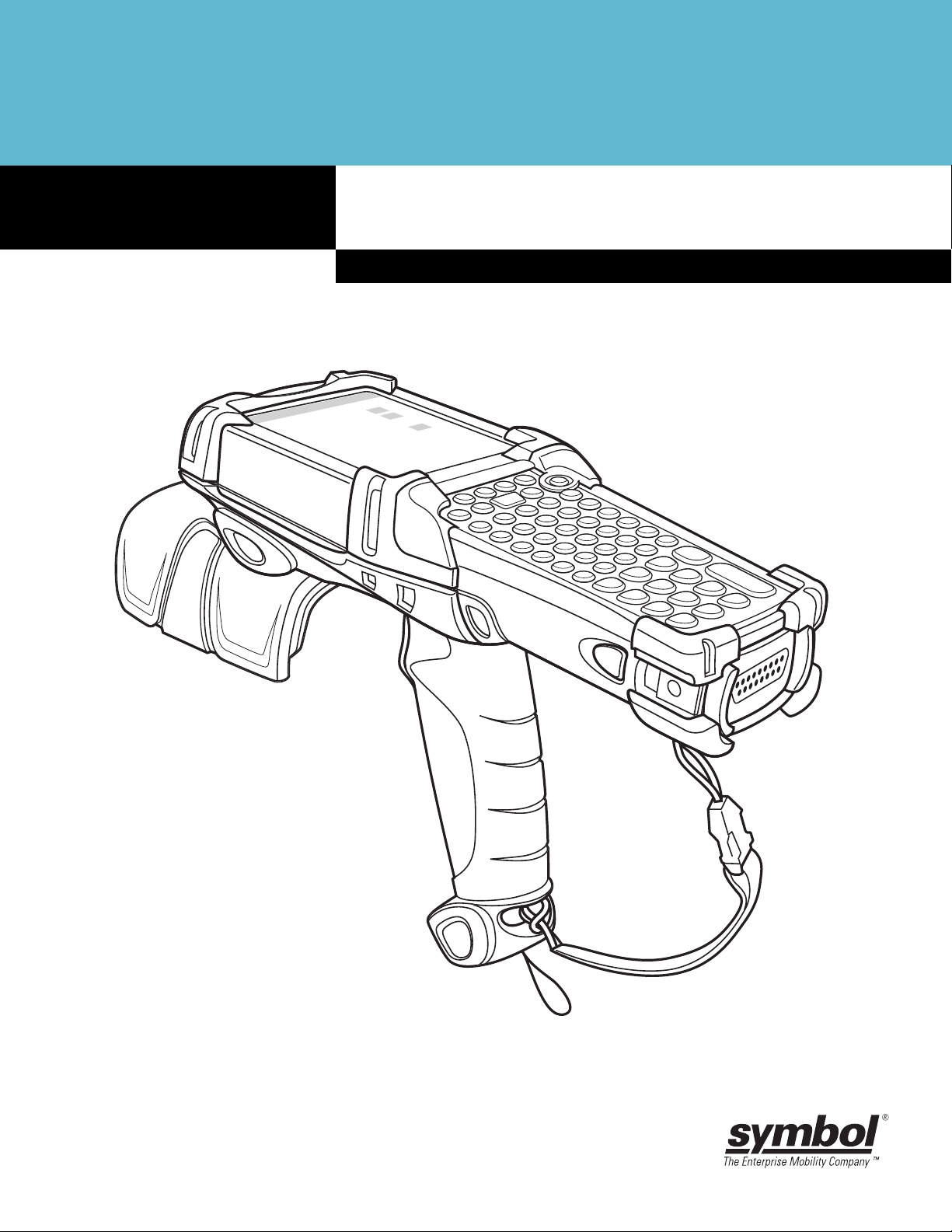
MC9090-G RFID Mobile Computer
RFID User Guide Supplement
Page 2

Page 3

MC9090-G RFID User Guide
72E-89962-01
Rev A
December 2006
Page 4

© 2006 by Symbol Technologies, Inc. All rights reserved.
No part of this publication may be reproduced or used in any form, or by any electrical or mechanical means, without
permission in writing from Symbol. This includes electronic or mechanical means, such as photocopying, recording, or
information storage and retrieval systems. The material in this manual is subject to change without notice.
The software is provided strictly on an “as is” basis. All software, including firmware, furnished to the user is on a
licensed basis. Symbol grants to the user a non-transferable and non-exclusive license to use each software or
firmware program delivered hereunder (licensed program). Except as noted below, such lice nse may not be assigned,
sublicensed, or otherwise transferred by the user without prior written consent of Symbol. No right to copy a licensed
program in whole or in part is granted, except as permitted under copyright law. The user shall not modify, merge, or
incorporate any form or portion of a licensed program with other program material, create a derivative work from a
licensed program, or use a licensed program in a network without written permission from Symbol. The user agrees to
maintain Symbol’s copyright notice on the li censed programs delivered hereunder, and to include the same on any
authorized copies it makes, in whole or in part. The user agrees not to decompile, disassemble, decode, or reverse
engineer any licensed program delivered to the user or any portion thereof.
Symbol reserves the right to make changes to any software or product to improve reliability, function, or design.
Symbol does not assume any product liability arising out of, or in connection with, the application or use of any product,
circuit, or application described herein.
No license is granted, either expressly or by implication, estoppel, or otherwise under any Symbol Technologies, Inc.,
intellectual property rights. An implied license only exists for equipment, circuits, and subsystems contained in Symbol
products.
Symbol, Spectrum One, and Spectrum24 are registered trademarks of Symbol Technologies, Inc. Bluetooth is a
registered trademark of Bluetooth SIG. Microsoft, Windows and ActiveSync are either registered trademarks or
trademarks of Microsoft Corporation. Other product names mentioned in this manual may be trademarks or registered
trademarks of their respective companies and ar e here b y ackno wle dg ed .
Symbol Technologies, Inc.
One Symbol Plaza
Holtsville, New York 11742-1300
http://www.symbol.com
Patents
This product is covered by one or more of the patents listed on the web site: www.symbol.com/patents
Page 5

Revision History
Changes to the original manual are listed below:
Change Date Description
Rev A 12/06 Initial release.
Page 6

Page 7

Table of Contents
Chapter 1
Patents........................................................................................................................... ii
Revision History............................................................................................................. iii
About This Guide
Introduction.................................................................................................................... v
Documentation Set .................................................................................................. v
Configurations................................................................................................................ vi
Chapter Descriptions ..................................................................................................... vii
Notational Conventions.................................................................................................. vii
Related Documents and Software................................................................................. viii
Service Information........................................................................................................ viii
Symbol Support Center............................................................................................ ix
Chapter 1: Getting Started
Introduction ................................................................................................................... 1-1
MC909X User Guide ............................................................................................... 1-1
Unpacking the Mobile Computer ................................................................................... 1-2
Accessories ................................................................................................................... 1-3
Getting Started .............................................................................................................. 1-4
Installing and Removing the Main Battery .................................................................... 1-4
Installing the Main Battery ....................................................................................... 1-4
Charging the Battery ..................................................................................................... 1-5
Charging the Main Battery and Memory Backup Battery ........................................ 1-5
Charging Spare Batteries ........................................................................................ 1-6
Removing the Main Battery ..................................................................................... 1-7
Starting the Mobile Computer ....................................................................................... 1-8
Calibrating the Screen .................................................................................................. 1-8
Checking Battery Status ............................................................................................... 1-8
Stylus ............................................................................................................................ 1-9
MC9090-G Strap ........................................................................................................... 1-10
Battery Management ..................................................................................................... 1-10
Battery Saving Tips ................................................................................................. 1-10
Changing the Power Settings ....................................................................................... 1-11
Changing the Display Backlight Settings ...................................................................... 1-11
Table of Contents
Page 8

vi MC9090-G RFID User Guide Suppliment
Changing the Keypad Backlight Settings ...................................................................... 1-11
Turning the Radios Off .................................................................................................. 1-12
WLAN Radio on Windows Mobile 5.0 ..................................................................... 1-12
Bluetooth and WWAN Radios on Windows Mobile 5.0 ........................................... 1-12
Chapter 2: Operating the MC9090-G RFID
Introduction ................................................................................................................... 2-1
Windows Mobile 5.0 Status Icons ................................................................................. 2-1
Status Bar ............................................................................................................... 2-1
Command Bar ......................................................................................................... 2-3
Speaker Icon ........................................................................................................... 2-4
Battery Icon ............................................................................................................. 2-5
Connectivity Icon ..................................................................................................... 2-5
Time Icon ................................................................................................................ 2-6
Instant Message Icon .............................................................................................. 2-6
E-Mail Icon .............................................................................................................. 2-6
Multiple Notification Icon ......................................................................................... 2-7
Locking the Mobile Computer ....................................................................................... 2-7
LED Indicators .............................................................................................................. 2-8
Keypads ........................................................................................................................ 2-8
53-Key Keypad for MC9090-G RFID....................................................................... 2-9
Keypad Special Functions ...................................................................................... 2-12
Using the Power Button ................................................................................................ 2-13
Using a Headset ........................................................................................................... 2-13
Data Capture ................................................................................................................ 2-14
Imaging ................................................................................................................... 2-14
Scanning Considerations ........................................................................................ 2-15
Scanning Bar Codes ............................................................................................... 2-15
Scan LED Indicator ................................................................................................. 2-16
Reading RFID Tags ...................................................................................................... 2-17
Resetting the Mobile Computer .................................................................................... 2-18
Windows Mobile 5.0 Devices .................................................................................. 2-18
Performing a Warm Boot .................................................................................. 2-18
Performing a Cold Boot ..................................................................................... 2-18
Waking the Mobile Computer .................................................................................. 2-19
Bluetooth ....................................................................................................................... 2-19
Chapter 3: Accessories
Introduction ................................................................................................................... 3-1
Keypads .................................................................................................................. 3-1
Cradles .................................................................................................................... 3-1
Snap-on Modules .................................................................................................... 3-2
Keypads ........................................................................................................................ 3-2
Keypad Removal ..................................................................................................... 3-2
Multi Media Card (MMC) / Secure Device (SD) Card ................................................... 3-4
Page 9

Table of Contents vii
Chapter 4: Maintenance & Troubleshooting
Introduction ................................................................................................................... 4-1
Maintaining the Mobile Computer ................................................................................. 4-1
Accessories ............................................................................................................. 4-2
Troubleshooting ............................................................................................................ 4-3
Mobile Computer ..................................................................................................... 4-3
Appendix A: Specifications
Technical Specifications ............................................................................................... A-1
Mobile Computer ..................................................................................................... A-1
Modem Module ....................................................................................................... A-6
Mobile Computer Pin-Outs ............................................................................................ A-7
Accessory CAM and MSR Pin-Outs ............................................................................. A-8
Appendix B: Keypad Special Keys
Introduction ................................................................................................................... B-1
Keypad .......................................................................................................................... B-1
Appendix C: Regulatory
Introduction ................................................................................................................... C-1
Accessory Power Supply Regulatory Compliance ........................................................ C-1
Index
Page 10

viii MC9090-G RFID User Guide Suppliment
Page 11

Chapter i
Chapter i
About This Guide
Introduction
This MC9090-G RFID User Guide Supplement provides the uniqu e set up and configuration procedu res for the
MC9090-G RFID mobile computers and accessories. This guide is intended as a supplement to the MC909X
User Guide, P/N: 72E-72215-xx. Procedures common to th e M C909X se rie s of p rod ucts are referenced to the
MC909X User Guide.
NOTE Screens and windows pictured in this guide are samples and may differ from actual screens.
Documentation Set
The documentation set for the MC9090-G RFID is divided into guides that provide information for specific user
needs.
About This Guide
•
Microsoft Application Guide - describes how to use Microsoft developed applications.
•
Symbol Application Guide - describes how to use Symbol developed applications.
•
MC909X User Guide - describes how to use the MC909X mobile computers.
•
MC9090-G RFID User Guide Supplement- describes how to use the MC9090-G RFID mobile
computer.
•
MC909X Integrator Guide - describes how to set up the MC909X mobile computers and the
accessories.
•
MC9090-G RFID Integrator Guide Supplement - describes how to set up the MC9090-G RFID mobile
computer and the accessories.
•
SMDK Help File - provides API information for writing applications.
Page 12
vi MC9090-G RFID User Guide Supplement
Configurations
This guide covers the following configurations:
Configuration Radios Display Memory
MC9090-G
RFID
WLAN
802.11b/g and
Bluetooth
Color 64 MB RAM/
128 MB Flash
Data
Capture
Imager Windows
Operating
System
Mobile 5.0
Professional
Keypads
53-key RFID
Page 13

Chapter Descriptions
Topics covered in this guide are as follows:
•
Chapter 1, Getting Started, provides information on charging the mobile computer battery and resetting.
•
Chapter 2, Operating the MC9090- G RFI D, describes the MC9090-G RFID operating procedures.
•
Chapter 3, Accessories, describes the accessories available for the mobile computer and how to use the
accessories.
•
Chapter 4, Maintenance & Troubleshooting, includes instructions on cleaning and storing the mobile
computer, and provides troubleshooting solutions for potential problems during mobile computer
operation.
•
Appendix A, Specifications, includes a table listing the technical specifications for the mobile computer.
•
Appendix B, Keypad Special Keys, includes a table listing the keypad special keys for the mobile
computer.
•
Appendix C, Regulatory, includes regulatory information for the mobile computer.
About This Guide vii
Notational Conventions
The following conventions are used in this document:
•
“Mobile computer” refers to a Symbol MC909X hand-held computer.
•
Italics are used to highlight the following:
- Chapters and sections in this guide
- Related documents
•
Bold text is used to highlight the following:
- Dialog box, window and screen names
- Drop-d o wn list an d list bo x na mes
- Check box and radio button names
- Icons on a screen
- Key names on a keypad
- Button na m es on a scre e n
•
Bullets (•) indicate:
- Action items
- Lists of alternatives
- Lists of required steps that are not necessarily sequential
•
Sequential lists (e.g., those that describe step-by-step procedures) appear as numbered lists
Page 14

viii MC9090-G RFID User Guide Supplement
Related Documents and Software
The following documents provide more information about the MC909X mobile computers.
•
MC9090-G RFID Quick Start Guide, p/n 72-89960-xx
•
MC9090-G RFID Windows® Mobile® 5.0 Regulatory Guide, p/n 72-89961-xx
•
MC909X User Guide, p/n 72E-72215-xx
•
MC909X Integrator Guide, p/n 72E-72216-xx
•
Symbol Application Guide for Symbol Devices, p/n 72E-68901-xx
•
Microsoft Applications for Mobile and WinCE 5.0 User Guide, p/n 72E-78456-xx
•
Symbol Mobility Developer Kit (SMDK) Help File, p/n 72E-38880-03
•
Symbol Mobility Developer Kits, available at: http://devzone.symbol.com.
•
Device Configuration Package (DCP for MC9090c50) and Platform SDK (PSDK909 0c50) for MC9090-G,
available at: http://devzone.symbol.com.
•
ActiveSync software, available at: http://www.microsoft.com.
For the latest version of this guide and all guides, go to: http://www.symbol.com/manuals.
Service Information
If an equipment problem occurs, contact the appropriate regional Symbol Support Center for contact
information. Before calling, have the model number, serial number and several bar code symbols at hand.
Call the Support Center from a phone near the scanning equipment so that the service person can try to talk
through the problem. If the equipment is found to be working properly and the problem is symbol readability,
the Support Center will request samples of bar codes for analysis at our plant.
If the problem cannot be solved over the phone, the e quipment ma y nee d to b e returne d for servicing. If tha t is
necessary, specific directions will be provided.
NOTE Symbol Technologies is not responsible for any damages incurred during shipment if the approved
shipping container is not used. Shipping the units improperly can possibly void the warranty.
Page 15

About This Guide ix
Symbol Support Center
For service information, warranty information or technical assistance contact or call the local Symbol Support
Center:
Country/Region Address Telephone
United States Symbol Technologies, Inc.
One Symbol Plaza
Holtsville, New York 11742-1300
Canada Symbol Technologies Canada, Inc.
5180 Orbitor Drive
Mississauga, Ontario, Canada L4W 5L9
United Kingdom Symbol Technologies
Symbol Place
Winnersh Triangle, Berkshire RG41 5TP
United Kingdom
Asia/Pacific Symbol Technologies Asia, Inc.
(Singapore Branch)
230 Victoria Street #12-06/10
Bugis Junction Office Tower
Singapore 188024
Australia Symbol Technologies Pty. Ltd.
432 St. Kilda Road
Melbourne, Victoria 3004
Österreich/Austria Symbol Technologies Austria GmbH
Prinz-Eugen Strasse 70 / 2.Haus
1040 Vienna, Austria
01-5055794-0 (Inside Austria)
1-800-653-5350
1-866-416-8545 (Inside Canada)
905-629-7226 (Outside Canada)
0800 328 2424 (Inside UK)
+44 118 945 7529 (Outside UK)
Tel: +65-6796-9600
Fax: +65-6337-6488
1-800-672-906 (Inside Australia)
+61-3-9866-6044 (Outside Australia
+43-1-5055794-0 (Outside Austria)
Danmark/Denmark Symbol Technologies AS
Dr. Neergaardsvej 3
2970 Hørsholm
Europe/Mid-East
Distributor
Operations
Suomi/Finland Oy Symbol Technologies
Kaupintie 8 A 6
FIN-00440 Helsinki, Finland
France Symbol Technologies France
Centre d'Affaire d'Antony
3 Rue de la Renaissance
92184 Antony Cedex, France
7020-1718 (Inside Denmark)
+45-7020-1718 (Outside Denmark)
Contact the local distributor or call +44 118
945 7360
9 5407 580 (Inside Finland)
+358 9 5407 580 (Outside Finland)
01-40-96-52-21 (Inside France)
+33-1-40-96-52-50 (Outside France)
Page 16

x MC9090-G RFID User Guide Supplement
Country/Region Address Telephone
Deutschland/
Germany
Italia/Italy Symbol Technologies Italia S.R.L.
Latin America
Sales Support
México/Mexico Symbol Technologies Mexico Ltd.
Nederland/
Netherlands
Symbol Technologies GmbH
Waldstrasse 66
D-63128 Dietzenbach, Germany
Via Cristoforo Columbo, 49
20090 Trezzano S/N Navigilo
Milano, Italy
2730 University Dr.
Coral Springs, FL 33065 USA
Torre Picasso
Boulevard Manuel Avila Camacho No 88
Lomas de Chapultepec CP 11000
Mexico City, DF, Mexico
Symbol Technologies
Kerkplein 2, 7051 CX
Postbus 24 7050 AA
Varsseveld, Netherlands
6074-49020 (Inside Germany)
+49-6074-49020 (Outside Germany)
2-484441 (Inside Italy)
+39-02-484441 (Outside Italy)
1-800-347-0178 (Inside United States)
+1-954-255-2610 (Outside United States)
954-340-9454 (Fax)
5-520-1835 (Inside Mexico)
+52-5-520-1835 (Outside Mexico)
315-271700 (Inside Netherlands)
+31-315-271700 (Outside Netherlands)
Norge/Norway Symbol’ s registe red and mailing address :
Symbol Technologies Norway
Hoybratenveien 35 C
N-1055 OSLO, Norway
Symbol’s repair depot and shipping
address:
Symbol Technologies Norway
Enebakkveien 123
N-0680 OSLO, Norway
+47 2232 4375
Page 17

About This Guide xi
Country/Region Address Telephone
South Africa Symbol Technologies Africa Inc.
Block B2
Rutherford Estate
1 Scott Street
Waverly 2090 Johannesburg
Republic of South Africa
España/Spain Symbol Technologies S.L.
Avenida de Bruselas, 22
Edificio Sauce
Alcobendas, Madrid 28108
Spain
Sverige/Sweden “Letter” address:
Symbol Technologies AB
Box 1354
S-171 26 SOLNA
Sweden
Visit/shipping address:
Symbol Technologies AB
Solna Strandväg 78
S-171 54 SOLNA
Sweden
11-809 5311 (Inside South Africa)
+27-11-809 5311 (Outside South Africa)
91 324 40 00 (Inside Spain)
+34 91 324 40 00 (Outside Spain)
Fax: +34.91.324.4010
Switchboard: 08 445 29 00 (domestic)
Call Center: +46 8 445 29 29 (international)
Support E-Mail:
Sweden.Support@se.symbol.com
If the Symbol product was purchased from a Symbol Business Partner, contact that Business Partner for
service.
Page 18

xii MC9090-G RFID User Guide Supplement
Page 19

Chapter 1
Chapter 1
Chapter 1
Getting Started
Introduction
This chapter lists the accessories for the mobile computer and explains how to install and char ge the batteries ,
replace the strap and start the mobile computer for the first time.
NOTE This MC9090-G RFID User Guide Supplement is intended as a supplement to the MC909X User Guide,
MC909X User Guide
The MC909X User Guide, P/N: 72E-72215-xx provides the following support information applicable to the
MC9090-G RFID mobile computer:
Getting Started
P/N: 72E-72215-xx. Procedures common to the MC909X series of products are referenced to the
MC909X User Guide.
•
Accessories; describes the accessories available for the mobile computers and how to set up power
connections and battery charging capabilities, where applicable.
•
Operating the MC909X; explains how to use the mobile computer. This includes instructions for
powering on and resetting the mobile comput er, entering and capturing data.
•
Using Bluetooth; explains how to perform Bluetooth functionality on the mobile computer.
•
Accessories; describes the accessories available for the mobile computer and how to use the
accessories with the mobile computer.
•
Maintenance & Troubleshooting; includes instructions on cleaning and storing the mobile computer,
and provides troubleshooting solutions for potential problems during mobile computer opera tion.
Page 20
1 - 2 MC9090-G RFID User Guide Suppliment
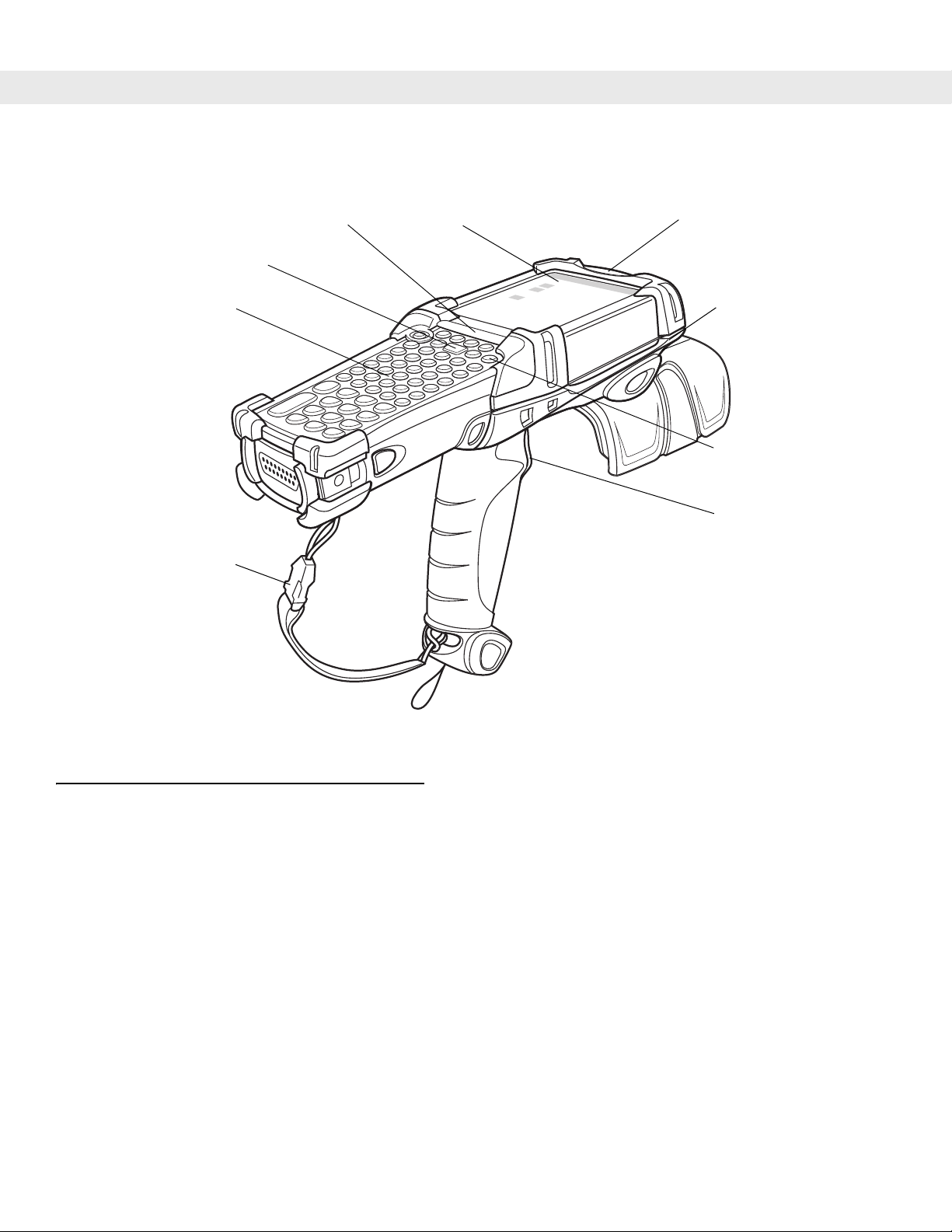
Scan Button
Keypad
Handstrap
Indicator LED Bar Touch Screen
Microphone (Windows
Mobile 5.0 only)
Headphone Jack
(Windows Mobile
5.0 only)
Power Button
Trigger
Figure 1-1
MC9090-G RFID Mobile Computer
Unpacking the Mobile Computer
Carefully remove all protective material from around the mobile computer and save the shipping container for
later storage and shipping.
Verify that all equip ment listed below was received:
•
Mobile computer
•
Lithium-ion battery
•
Strap, attached to the mobile computer
•
Stylus, in the stylus silo
•
Regulatory Guide
•
Quick Start Guide (poster)
Inspect the equipment for damage. If any equipment is missing or damaged, contact the Symbol Technologies
Support Center immediately. See page ix for contact information.
Page 21

Accessories
Table 1-1 lists the accessories available for the MC909X:
Getting Started 1 - 3
Table 1-1
Cable Adapter Module
(CAM)
MC9090-G RFID Accessories
Accessory Description
Snap-on required to connect the following cables to the mobile computer.
•
AC line cord (country-specific) and power supply, charges the mobile
computer.
•
Auto charge cable, charges the mobile computer using a vehicle’s
cigarette lighter.
•
DEX cable, connects the mobile computer to a vending machine.
•
Serial cable, adds serial communication capabilities.
•
USB cable, adds USB communication capabilities.
•
Printer cable, adds printer communication capabilities.
Four Slot Charge Only
Charges the mobile computer main battery.
Cradle
Four Slot Ethernet Cradle Charges the mobile computer main battery and synchronizes the mobile
computer with a host computer through an Ethernet connection.
Four Slot Spare Battery
Charges up to four mobile computer spare batteries.
Charger
Keypads (Optional) Application specific keypads.
Magnetic Stripe Reader
Snaps on to the mobile computer and adds magstripe read capabilities.
(MSR)
Modem Module Enables data communication between the mobile computer and a host
computer, remotely through the phone lines, and synchronizes information
between the mobile computer and a host computer.
Multimedia Card (MMC) Provides secondary non-volatile storage.
Single Slot Serial/USB
Cradle
Charges the mobile computer main battery and a spare battery. It also
synchronizes the mobile computer with a host computer through either a serial
or a USB connection.
Software Symbol Mobility Developer Kits available at: http://devzone.symbol.com.
Device Configuration Package (DCPforMC9090c50) and Platform SDK
(PSDK9090c50) for MC9090-G, available at: http://devzone.symbol.com.
Spare lithium-ion battery Replacement battery.
Stylus Performs pen functions.
Universal Battery Charger
Adapts the UBC for use with the Series 9000 batteries.
Adapter
Wall Mounting Bracket and
Use for wall mounting applications.
Shelf Slide
Page 22
1 - 4 MC9090-G RFID User Guide Suppliment
Getting Started
In order to start using the mobile computer for the first time:
•
Install the main battery
•
Charge the main battery and backup battery
•
Start the mobile computer
•
Configure the mobile computer
The main battery can be charged before or af ter it is inst a lled. Use one of the sp are b attery ch argers to charge
the main battery (out of the mobile computer), or one of the cradles to charge the main battery installed in the
mobile computer.
Installing and Removing the Main Battery
Installing the Main Battery
Before using the mobile computer , install a lithium-ion battery by sliding the battery into the mobile computer as
shown in Figure 1-2.
NOTE Ensure the battery is fully inserted. Two audible clicks can be heard as the battery is fully inserted. A
partially inserted battery may result in unintentional data loss.
When a battery is fully inserted in a mobile computer for the first time, upon the mobile computer’s first power
up, the device boots and powers on automatically.
Figure 1-2
Installing the Main Battery
Page 23

Charging the Battery
Charging the Main Battery and Memory Backup Battery
Before using the mobile computer for the first time, charge the main battery until the amber charge indicator
light remains lit (see T able 1-2 on page 1-6 for charge status indications). The main battery fully ch arges in less
than four hours. The mobile computer can be charged using a cradle, the CAM, or the MSR with the
appropriate power supply.
The mobile computer is also equipped with a memory backup battery which automatically charges from the
main battery whether or not the mobile computer is operating or is in suspend mode. The memory backup
battery retains data in memory for at least 30 minutes when the mobile computer's main battery is removed or
fully discharged. When the mobile computer is used for the first time or after the memory backup battery has
fully discharged, the memory backup battery requires approximately 15 hours to fully charge. Do not remove
the main battery from the mobile computer for 15 hours to ensure that the memory backup battery fully
charges. If the main battery is removed from the mobile computer or the main battery is fully discharged, the
memory backup battery completely discharges in several hours.
When the main battery reaches a very low battery state, the combination of main battery and backup battery
retains data in memory for at least 72 hours.
Getting Started 1 - 5
NOTE Do not remove the main battery within the first 15 hours of use. If the main battery is removed before
the backup battery is fully charged, data may be lost.
Use the following to charge batteries:
•
Cradles: The mobile computer slips into the cr adles for cha rging the ba tter y in the mobile com puter (a nd
spare batteries, where applicable). For detailed cradle setup and charging procedures refer to the
MC909X User Guide.
- Single Slot Serial/USB Cradle.
- Four Slot Ethernet Cradle
- Four Slot Charge Only Cradle
•
Accessories: The mobile computer snap-on accessories provide charging capability, when used with one
of the accessory charging cables. For detailed snap-on setup and charging procedures refer to the
MC909X User Guide.
- CAM
- MSR
•
Chargers: The mobile computer spare battery charging accessories are used to charge batteries that are
removed from the mobile computer. For detailed spare battery charging accessories setup and charging
procedures refer to the MC909X User Guide.
- Single Slot Serial/USB Cradle
- Four Slot Spare Battery Charger
- Universal Battery Charger (UBC) Adapter
NOTE To achieve the best battery life in mobile computers with multiple radios, turn off the radios that are not
being used. This can be accomplished via the SetDevicePower() API (refer to the SMDK Help File for
Symbol Mobile Computers) or via the Control Panel application (tap Start - 9000 Demo - Ctl Panel icon).
Page 24

1 - 6 MC9090-G RFID User Guide Suppliment
To charge the main battery:
1. Ensure the accessory used to charge the main battery is connected to the appropriate power source.
2. Insert the mobile computer into a cradle or attach the appropriate snap-on module.
3. The mobile computer starts to charge automatically. The amber charge LED, in the Indicator LED Bar,
lights to indicate the charge status. See Table 1-2 for charging indications.
The main battery usually fully charges in less than four hours.
Table 1-2
Mobile Computer LED Charge Indicators
LED Indication
Off Mobile computer not in cradle or connected to a CAM or MSR. Mobile computer not
placed correctly. Charger is not powered.
Fast Blinking Amber Error in charging; check placement of the mobile computer.
Slow Blinking Amber Mobile computer is charging.
Solid Amber Charging complete.
Charging Spare Batteries
Use the following three accessories to charge spare batteries:
•
Single Slot Serial/USB Cradle
•
Four Slot Spare Battery Charger
•
UBC Adapter
To charge a spare battery:
1. Ensur e the accessory used to charge the spare battery is connecte d to th e ap p ro pr iate power source.
2. Insert the spare battery into the accessory’s spare battery charging slot with the charging contacts facing
down (over the charging pins) and gently press down on the battery to ensure proper contact.
3. The battery starts to charge automatically. The amber charge LED on the accessory lights to show the
charge status.
The spare battery usually fully charges in less than four hours.
Page 25

Getting Started 1 - 7
Removing the Main Battery
To remove the main battery:
1. Prior to removing the battery, press the red Power button. This sets the mobile computer to suspend
mode.
2. Press the primary battery release(s). The battery partially ejects from the mobile computer.
3. Pause 3 to 4 seconds while the mobile computer performs battery removal shutdown.
4. Press the secondary battery release, on top of the battery , and slide th e battery out of the mobile computer.
Primary Battery Releases
Secondary Battery Release
Figure 1-3
1
2
3
Removing the Main Battery - MC9099-G RFID
1
Page 26

1 - 8 MC9090-G RFID User Guide Suppliment
Starting the Mobile Computer
Press the red Power button to turn on the mobile computer. If the mobile computer does not power on, perform
a cold boot. See Resetting the Mobile Computer on page 2-18.
NOTE When a battery is fully inserted in a mobile computer for the first time, upon the first power up, the
mobile computer boots and powers on automatically.
When the mobile computer is powered on for the first time, it initializes its system. The Symbol splash screen
(Figure 1-4) appears for a short period of time.
Figure 1-4
Symbol Splash Window
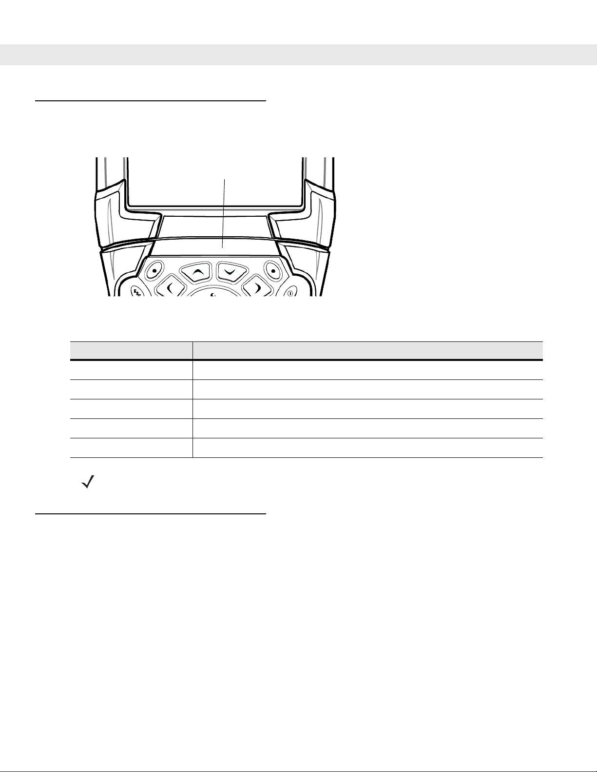
Calibrating the Screen
To calibrate the screen so the cursor on the touch screen aligns with the tip of the stylus:
1. Using the stylus carefully press and briefly hold the tip of stylus on the center of each target that appears
on the screen.
NOTE To re-calibrate the screen at anytime, press the blue FUNC and ESC keys on the mobile computer to
launch the calibration screen application.
2. Repeat as the target moves around the screen or press ESC to cancel.
Checking Battery Status
To check whether the main battery or backup battery in the mobile computer is charged:
•
On Windows Mobile 5.0 devices: tap Start > Settings > System tab > Power icon to display the Power
window.
To save battery power, set the mobile computer to turn off after a specified number of minutes.
Page 27

Stylus
Getting Started 1 - 9
To remove the stylus, pull the stylus cord down and outward to remove the stylus.
Figure 1-5
Removing the Stylus
Use the mobile computer stylus for selecting items and entering information. The stylus functions as a mouse.
•
Tap: Touch the screen once with th e sty lus to pre ss op tio n bu tto n s an d open me nu item s.
•
Tap and Hold: Tap and hold the stylus on an item to see a list of actions available for that item. On the
pop-up menu that appears, tap the action to perform.
•
Drag: Hold the stylus on the screen and drag across the screen to select text and images. Drag in a list to
select multiple items.
Page 28
1 - 10 MC9090-G RFID User Guide Suppliment
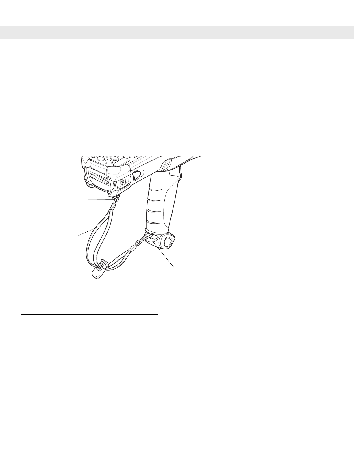
MC9090-G Strap
The strap may be moved to either the left or right side of the mobile computer to suit user preferences.
To reposition the strap:
1. Disconnect the metal clip at the handle.
2. Open strap loop and slide the handstrap through the loop.
3. Slide the loop out of the connector post.
4. Reverse the procedure to re-attach the strap. Two strap conne ctors are provided on th e mobile computer’s
main body. The handstrap may be attached to either connector.
Strap Loop
Handstrap
Figure 1-6
Reposition the Strap
Battery Management
Battery Saving Tips
•
Leave the mobile computer connected to AC power at all times when not in use.
•
Set the mobile computer to turn off after a short period of non-use.
•
Set the display and keyboard backlight to turn off after a short period of non-use.
•
Turn off all wireless radio activity when not in use.
•
Power off the mobile computer when charging to charge at a faster rate.
Metal Clip
Page 29

Changing the Power Settings
To set the mobile computer to turn off after a short period of non-use:
1. On devices with Windows Mobile 5.0, tap Start > Settings > System tab > Power icon > Advanced tab.
2. Select the On battery power: Turn off device if not used for: check box and select a value from the
drop-down list box.
3. Tap OK.
Changing the Display Backlight Settings
To change the display backlight settings in order to conserve more battery power:
1. On devices with Windows Mobile 5.0, tap Start > Settings > System tab > Backlight icon > Battery Power
tab.
2. Select the On battery power: Disable backlight if not used for: check box and select a value from the
drop-down list box.
Getting Started 1 - 11
3. Tap the Brightness tab.
4. Tap the Disable backlight check box to completely turn off the display backlight.
5. Use the slider to set the brightness of the backlight. Set it to a low value to save battery power.
6. Tap OK.
Changing the Keypad Backlight Settings
To change the keypad backlight settings in order to cons er ve mor e battery power:
1. Tap Start > Settings > System tab > Keylight icon > Battery Power tab.
2. Select the On battery power: Disable keylight if not used for: check box and select a value from the
drop-down list box.
3. Tap the Advanced tab.
4. Tap the Disable keylight check box to completely turn off the display backlight.
5. Tap OK.
Turning the Radios Off
WLAN Radio on Windows Mobile 5.0
To turn off the WLAN radio tap the Wireless Connection Status icon at the bottom of the Today screen and
select
Disable Radio. A red X appears across the icon indicating that the radio is disabled (off).
Page 30

1 - 12 MC9090-G RFID User Guide Suppliment
Wireless Connection Status Icon
Figure 1-7
To turn the radio back on, tap the
Enable Radio. The red X disappears from the icon indicating that the radio is enabled (on).
Wireless Connection Status Icon
Wireless Connection Status icon at the bottom of the Today screen and select
Bluetooth and WWAN Radios on Windows Mobile 5.0
NOTE The Flight Mode feature only turns off the WWAN and Bluetooth radios. The WLAN radio must be turned
off separately.
To turn off the Bluetooth and WWAN radios, tap the Connectivity icon (on non-WWAN devices) or the
Antenna/Signal icon (on WWAN devices) and select Turn On Flight Mode .
NOTE On the MC9090, it takes two to five seconds for the radio to shut down.
To turn on the Bluetooth and WWAN radios, tap the
Antenna/Signal icon (on WWAN devices) and select Turn Off Flight Mode.
NOTE On the MC9090, wait 20 to 40 seconds for the radio to power on. During this time do not suspend the
mobile computer or remove the battery. If the mobile computer is suspended or the battery is removed,
warm boot the mobile computer.
Connectivity icon (on non-WWAN devices) or the
The MC909X User Guide, P/N: 72E-72215-xx provides the Bluetooth support information applicable to the
MC9090-G RFID mobile computer.
Page 31

Chapter 2
Chapter 2
Chapter 2
Operating the MC9090-G RFID
Introduction
This chapter explains the physical buttons, status icons and controls on the mobile computer, how to use the
mobile computer, including instructions for powering on and resetting the mobile computer, using the stylus
and a headset, entering information and scanning.
Windows Mobile 5.0 Status Icons
Status Bar
The Status Bar at the top of the window displays the current time, battery status and communication status.
Operating the MC9090-G RFID
Start Button
Figure 2-1
Statu s icons are shown in the
icon displays the corresponding dialog box the settings then be changed or adjusted. The st atus icons listed in
Table 2-1 on the
Status Bar
Status Bar to indicate present status of the mobile computer. Tapping each status
Status Bar may be located at th e top of th e scr ee n.
Stat us Ico n s
Volume Icon
Date/Time
Page 32

2 - 2 MC9090-G RFID User Guide Suppliment
Table 2-1
Icon Function Description
Speaker Turns all sounds on and off.
Battery Backup battery is very low.
Main battery is charging.*
Main battery is low.
Main battery is very low.
Main battery is full.*
Connectivity Connection is active.
Synchronization is occurring.
Status Icons
GPRS available.
GPRS in use.
EGPRS available.
EGPRS in use.
WWAN Call missed.
Voice call.
Voice call in progress.
Calls are forwarded.
Call on hold.
Antenna/signal icon: wireless on/good signal.
Antenna/signal icon: wireless off.
Antenna/signal icon: no service or searching.
Roaming icon. Outside of the home area.
Missing SIM Card icon: SIM Card not installed or installed improperly.
Instant Message Notification that one or more instant messages were received.
E-Mail Notification that one or more e-mail messages were received.
* Only appears in the Time and Next Appointment dialog box.
Page 33

Operating the MC9090-G RFID 2 - 3
Table 2-1
Icon Function Description
Status Icons (Continued)
Voice Mail Notification that one or more voice messages were received.
Time and Next
Displays current time in analog or digital format.
Appointment
Multiple Notifications There are more notification icons than can be displayed. T ap to display
remaining icons.
* Only appears in the Time and Next Appointment dialog box.
Command Bar
The icons listed in Table 2-2 on the Command Bar may be located at the bottom of the screen.
Status Icons
Figure 2-2
Table 2-2
Icon Description
Command Bar
Command Bar Icons
Wireless connection status icon. Indicates WLAN signal strength and opens the Wireless
Applications menu.
The
Bluetooth Enabled
The
Bluetooth Disabled
Bluetooth Communication
The
icon appears in the task tray and indicates that the Bluetooth radio is on.
icon appears in the task tray and indicates that the Bluetooth radio is off.
icon appears in the task tray and indicates that the mobile computer
is communicating with another Bluetooth device.
The
ActiveSync
icon appears in the task tray and indicates an active conn ection betwe en the mobile
computer and the development computer.
Page 34

2 - 4 MC9090-G RFID User Guide Suppliment
Speaker Icon
Adjust the system volume using the Speaker icon in the Status bar.
1. Tap the Speaker icon. The Volume dialog box appears.
Figure 2-3
2. Tap and move the slide bar to adjust the volume.
3. Select the On or Off radio button to turn the volume on or off.
Volume Dialog Box
NOTE When not in a call, the phone volume slider adjusts the volume of the ringer. When in a call, adjusts the
volume of the call audio.
NOTE Use can also adjust the system volume using the Sounds & Notifications window or by pressing the
Blue key and 6 or the Blue key and 7.
Page 35

Operating the MC9090-G RFID 2 - 5
Battery Icon
Battery icons display on the Title Bar when the main battery or backup battery power falls below a
predetermined level. A
Battery dialog box also appears indicating the status of the main or backup battery.
Figure 2-4
View the battery status using the
Battery Status Dialog Box
Power window.
Connectivity Icon
The Connectivity icon indicates the communication st atus of the terminal when it’ s connecting to the internet or
host computer.
Figure 2-5
Connectivity Dialog Box
Page 36

2 - 6 MC9090-G RFID User Guide Suppliment
Time Icon
The Time icon displays the current time in a digital or analog format. To change the time format, tap and hold
the
Time icon until a menu appears. Select the desired format.
Analog ClockDigital Clock
Figure 2-6
Time Icon Format Menu
To display current date, time and appointments:
1. Tap the Time icon to display the Time and Next Appointment dialog box.
Battery Status Icon
Upcoming Appointments
Figure 2-7
2. The dialog box displays the current date and time, the battery status and any upcoming appointments in
the
Calendar.
Time and Next Appointment Dialog Box
Current Date and Time
Instant Message Icon
The Instant Message icon provides a notification when MSN Messenger has received a new incoming message.
Figure 2-8
MSN Messenger Dialog Box
E-Mail Icon
The E-Mail icon provides a notification when an incoming e-mail is received.
Figure 2-9
New E-mail Messages Dialog Box
Page 37

Operating the MC9090-G RFID 2 - 7
Multiple Notification Icon
The Multiple Notification icon appears when two or more message notifications occur. Tap the icon to display
the multiple notification icons.
Figure 2-10
Multiple Notifications Icon
Locking the Mobile Computer
Use the Device Lock feature to prevent use of the device. When locked, the mobile com puter does not respond
to screen or keypad input. To lock the device, tap the
Figure 2-11
To unlock the device and free it for use, tap
Device Locked/Unlocked Icons
Device unlocked icon. The icon changes to locked.
Unlock.
Figure 2-12
Tap Unlock on the
Unlock Device Window
Unlock Device window.
Page 38
2 - 8 MC9090-G RFID User Guide Suppliment
LED Indicators
The MC9090-G RFID has an LED Indicator Bar that cont ai ns LEDs that indicate scanning and charg ing status.
Table 2-3 describes the LED indications.
LED Indicator Bar
Table 2-3
Solid Red Laser enabled, scanning/imaging in process.
Solid Green Successful decode/capture.
Slow Blinking Amber Main battery in mobile computer is charging.
Fast Blinking Amber Error in charging; check placement of the mobile computer.
Solid Amber Main battery in mobile computer is fully charged.
Keypads
The mobile computer has the following modular keypad:
The modular keypads can be removed in the fie ld, as necessary. The MC909X User Guide, P/N: 72E-72215-xx
provides the keypad support information applicable to the MC9090-G RFID mobile computer.
Figure 2-13
LED State Indication
NOTE The RFID read enabled and successful RFID tag read indications are displayed on the screen, not on the
•
53-key keypad
MC909X LEDs Indicator Bar
Mobile Computer LED Indications
LED indicators.
Page 39

Operating the MC9090-G RFID 2 - 9
53-Key Keypad for MC9090-G RFID
The 53-key keypad contains a Power button, application keys, scroll keys and function keys. The keypad is
color-coded to indicate the alternate function key (blue) values. Note that keypad functions can be changed by
an application so the mobile computer’s keypad may not function exactly as described. See Table 2-4 on page
2-10 for key and button descriptions and Table 2-5 on page 2-12 for the keypad’s special functions.
Figure 2-14
53-Key Keypad for MC9090-G RFID
Page 40

2 - 10 MC9090-G RFID User Guide Suppliment
Table 2-4
Power (red) Turns the mobile computer on and off.
Green/Red Dot To use a key as an application key (APP key) on the keyboard, a new keyboard
Scan (yellow) Activates the scanner/imager in a scan enabled application.
53-Key Descriptions
Key Description
Performs a warm boot and a cold boot. See
2-18
for information about performing a warm and cold boot.
remap table must be created and installed. However, the Green/Red dot keys can be
remapped as APP keys through the registry.
Create an XML Provisioning file with the following entries:
Characteristic type
=“HKEY_LOCAL_MACHINE\HARDWARE\DEVICEMAP\KEYBD”
Parm name = “GreenKeyOverride” value = “xx”, where xx is the new APP key code.
Parm name = “RedKeyOverride” value = “xx”, where xx is the new APP key code.
Refer to the MC909X Integrator Guide for instruction on updating the registry using
XML Provisioning.
This sends an APP key code, instead of their original key codes, when the green or
red dot key is pressed.
Windows Mobile 5.0 Devices on page
Scroll Up and Down Moves up and down from one item to another.
Increases/decreases specified values.
Scroll Left and Right Moves left and right from one item to another.
Increases/decreases specified values.
ESC Exits the current operation.
Alpha Use the alpha keys for alphabetic characters.
SPACE/BKSP Space and backspace functions.
Numeric/Application Numeric value keys - can have applications assigned with function key(s).
The
F6
and F7 keys cannot be remapped and are dedicated by the Operating
System to control volume level. When these keys are pressed, Shell.exe traps them
and displays the volume adjustment window. To get these keys to an application, call
GXOpenInput() at the beginning of the application and call GXCloseInput() at the
end of the application. This redirects all of the k ey event s to an application, incl uding
the
F6
and F7 keys.
Page 41

Operating the MC9090-G RFID 2 - 11
Table 2-4
53-Key Descriptions (Continued)
Key Description
Function (blue) Press and release the blue function key to activate the keypad alternate functions
LED
(shown on the keypad in blue). The LED above the key lights and the icon
appears on the taskbar on WinCE devices or the icon appears at the bottom of
the screen on Windows Mobile 5.0 devices. Press and release the blue functio n key
again to return to the normal keypad functions.
Control Press and release the CTRL key to activate the keypad alternate CTRL functions.
LED
The LED above the key lights and the icon appears on the taskbar on WinCE
devices or the icon appears at the bottom of the screen on Windows Mobile 5.0
devices.
Press the Blue key followed by the CTRL key to activate the keypad alternate ALT
functions. The icon appears on the taskbar on WinCE devices or the icon
ALT
appears at the bottom of the screen on Windows Mobile 5.0 devices.
Shift Press and release the SHIFT key to activate the keypad alternate SHIFT functions.
The icon appears on the taskbar on WinCE devices or the icon appears at
the bottom of the screen on Windows Mobile 5.0 devices. Press and release the
SHIFT key again to return to the normal keypad functions.
Period/Decimal Point Produces a period for alpha entries and a decimal point for numeric entries.
Star Produces an asterisk.
Enter Executes a selected item or function. The default behavior of the ENT (Enter) key
sends an extra character, which causes a Microsoft Word or Notes application to
exit. To make the applications work properly, create an XML Provisioning file with the
following entries:
Characteristic type
=”HKEY_LOCAL_MACHINE\HARDWARE\DEVICEMAP\KEYBD”
Para name = “SpecialEnterTabKey” value = 0
Refer to the MC909X Integrator Guide for instruction on updating the registry using
XML Provisioning.
Page 42
2 - 12 MC9090-G RFID User Guide Suppliment
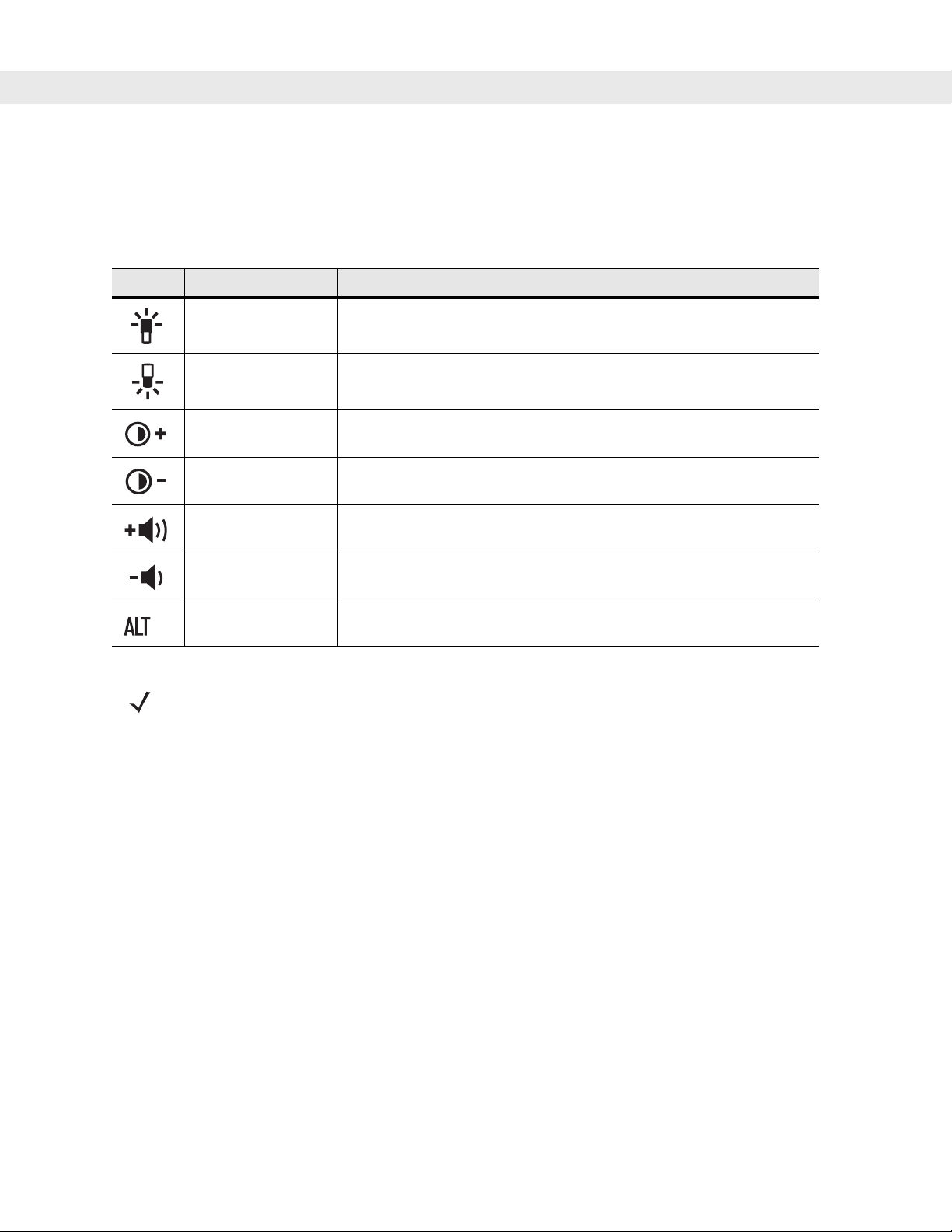
Keypad Special Functions
The keypad special functions are color coded on the keypads. For example, on the 53-key keypad, the display
backlight icon is blue indicating that the blue function key must be selected first to access the display backlight.
Table 2-5
Icon 53-Key, Keypad Special Function
Keypad Special Functions
Blue key +
Blue key +
Blue key +
Blue key +
Blue key +
Blue key +
* Blue key +
NOTE Use of display and keypad backlighting can significantly reduce battery life.
Z
X
D
I
H
M
CTRL
Turns on and off the display backlight.
Turns on and off the keypad backlight.
Color units: Increases display backlight intensity.
Color units: Increases display backlight intensity.
Increases scan decode beeper volume.
Decreases scan decode beeper volume.
Enables Alt keypad functions.
Page 43

Using the Power Button
Press the red Power button to turn the mobile computer screen on and off (suspend mode). The mobile
computer is on when the screen is on and the mobile computer is in su spend mode whe n the screen is o ff. For
more information, see Starting the Mobile Computer on page 1-8.
The Power button is also used to reset the mobile computer by performing a warm or cold boot.
•
On Windows Mobile 5.0
- Warm Boot (Soft Reset) - Resets the mobile computer. Operating system and all applications are
restarted. File storage is preserved.
- Cold Boot (Hard Reset) - Resets the mobile computer Operating system and all applications are
restarted. File storage is preserved. Real-Time Clock (RTC) is reset. Normally only used when a
Warm Boot does not initiate.
NOTE Applications that are added to the Application folder are not removed when a cold boot is performed. The
Application folder is in flash memory.
For information about booting the mobile computer, see Windows Mobile 5.0 Devices on page 2-18.
Operating the MC9090-G RFID 2 - 13
Using a Headset
Use a stereo headset or a a Bluetooth headset for audi o co mmu nication when a n a udio enabled application is
used. To use a headset, plug the headset jack into the audio connector on the side of the mobile computer.
Ensure that the mobile computer volume is set ap propriately before p utting the headset on. When a he adset is
plugged into the jack, the speakerphone is muted. The MC909X User Guide, P/N: 72E-72215-xx provides the
headset support information applicable to the MC9090-G RFID mobile computer
Page 44

2 - 14 MC9090-G RFID User Guide Suppliment
Data Capture
The mobile computers use an integrated imager to collect data by decoding one dimensional bar codes
(including RSS) and two dimensional bar codes (including PDF417 and DataMatrix), and capture and
download images to a host for a variety of imaging applications.
Imaging
The mobile computers with an integrated imager have the following features:
•
Omnidirectional reading of a variety of bar code symbologies, including the most popular linear, postal,
PDF417 and 2-D matrix code types.
•
The ability to capture and download images to a host for a variety of imaging applications.
•
Advanced intuitive laser aiming for easy point-and-shoot operation.
The imager uses digital camera technology to take a digit al picture of a bar code, stores the resulting image in
its memory and executes state-of-the-art software decoding algorithms to extract the data from the image.
Aiming the Imager
The mobile computer integrated imager projects a laser aiming pattern (field of view) similar to those used on
cameras. The aiming pattern is used to position the bar code or object within the field of view.
Figure 2-15
Laser Aiming Pattern (Field of View)
Operational Modes
Mobile computers with an integrated imager have three modes of operation: Decode Mode, Pick List Mode and
Image Capture Mode. All modes are activated by pulling the trigger or pressing the Scan button.
Decode Mode
This mode allows the user to decode a bar code when a si ngle b ar code in the mo bile co mputer’s field o f vi ew.
In this mode the Imager attempts to locate and decode enabled bar codes within its field of view. The Imager
remains in this mode as long as the trigger is pulled, or until a bar code is decoded.
Pick List Mode
Pick List mode allows the user to selectively decode a bar code when more than one bar code is in the m obile
computer’s field of view. By moving the aiming crosshair over the wanted bar code the user can selectively
read only the required bar code. This feature is particularly valued for pick lists containing multiple bar codes
and manufacturing or transport labels containing more than one bar code type (either 1D or 2D).
Image Capture Mode
This mode allows the user to capture an image within the mob ile computer’s field of view. The user can use the
mobile computer to capture signatures or images of items like damaged boxes.
Page 45
Operating the MC9090-G RFID 2 - 15
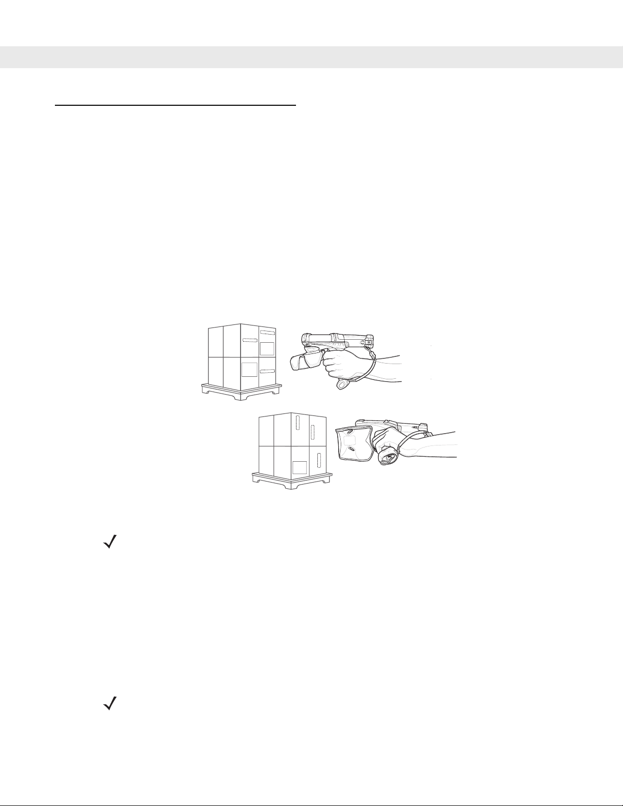
Scanning Considerations
Typically, scanning is a simple matter of aim, scan/decode and a few quick trial efforts master it. However, two
important considerations can be used to optimize any scanning performance:
•
Range
Any scanning device decodes well over a particular working range — minimum and maximum distances
from the bar code. This range varies according to bar code density and scanning device optics.
Scanning within range brings quick and constant decodes; scanning too close or too far away prevents
decodes. Move the scanner closer and further away to find the right working r ange for the bar code s being
scanned. However, the situation is complicated by the availability of various integrated scanning modules.
The best way to specify the appropriate working range per bar code density is through a chart called a
decode zone for each scan module. A decode zone simply plots working range as a function of minimum
element widths of bar code symbols.
•
Angle
Scanning angle is important for promoting quick de codes. Do not scan at too sharp an angle; the scanner
needs to collect the image to make a successful decode. Practice quickly shows what tolerances work.
NOTE Contact the Symbol Support Center if chronic scanning difficulties develop. Decoding of properly printed
bar codes should be quick and effortless.
Scanning Bar Codes
1. Ensure that a scan enabled application is loaded on the mobile computer.
2. Aim the scan exit window at the bar code.
3. Pull the trigger.
•
Place the bar code in any orientation within the aiming pattern. Ensure the entire symbol is within the
rectangular area formed by the brackets in the aiming pattern. The red laser aiming pattern turns on to
assist in aiming. If necessary, the mobile computer turns on it s red LED to illuminate the target bar code.
The green scan LED lights and an audible beep sounds, by default, to indicate the bar code was
decoded successfully. Note that when the mobile computer is in Pick List Mode, the bar code is not
decoded until the crosshair is touching the bar code.
Linear bar code
Figure 2-16
Symbol
View Finder
(Aiming Pattern)
Bar Code Centered in Aiming Pattern
PDF417 symbol
Page 46
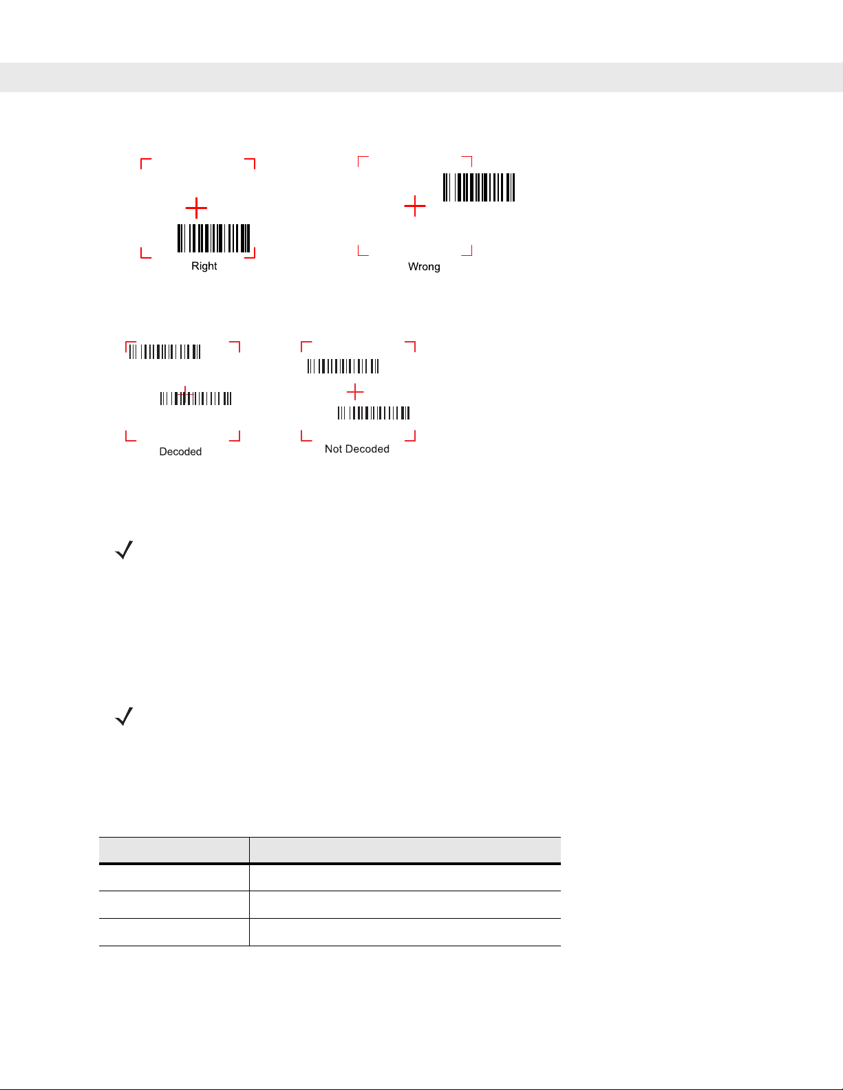
2 - 16 MC9090-G RFID User Guide Suppliment
Figure 2-17
Figure 2-18
4. Release the trigger.
NOTE Imager decoding usually occurs instantaneously . The mobile computer repeats the steps required to take
Bar Code Not Centered in Aiming Pattern
Pick List Mode with Multiple Bar Codes in Aiming Pattern
a digital picture (image) of a poor or difficult bar code, as long as the trigger remains pulled.
Scanning Tips
Optimal scanning distance varies with bar code density and scanner optics.
•
Hold the scanner farther away for larger symbols.
•
Move the scanner closer for symbols with bars that are close together.
NOTE Scanning procedures depend on the application and mobile computer configuration. An application may
use different scanning procedures from the one listed above.
Scan LED Indicator
The Indicator LED bar on the mobile computer provides a visual indication of the scan status.
Table 2-6
Off Not scanning.
Solid Red Laser enabled, scanning/imaging in process.
Solid Green Successful decode.
Scan LED Indicators
LED Status Indication
Page 47
Reading RFID Tags
When in the RFID read mode, press the trigger and the mobile computer interrogates all of the Gen2
(configurable for Class 0 and Class 1) RFID tags within the radio frequency (RF) field of view. The mobile
computer captures data from each new tag found. When the trigger is released, the mobile computer stops
interrogating tags. In addition, RFID tag data can be stored on the mobile computer. Using the MC9090-G
RFID sample application, tags that are read display in the main RFID Tags window, see Figure 5-24 on page
5-28.
For more information about reading RFID tags and using MC9000-G RFID mobile computers, see RFID on
page 5-28.
To Read RFID Tags:
1. Ensure that an RFID tag reader enabled application is loaded on the mobile computer.
2. Aim the scan exit window at the tag.
Operating the MC9090-G RFID 2 - 17
Figure 2-19
NOTE For a successful tag read, the allowable read distance from the front of the mobile computer scan exit
3. Position the mobile computer horizontally or vertically (as shown in Figure 2-19), depending on the
RFID Tag Read
window to the tag is 0.2 ft. - 10 ft. (0.061 m to 3.1 m). Reader motion horizontally and/or vertically may
enhance tag reading ability.
orientation of the tag.
4. Pull the trigger.
5. An audible beep sounds, by default, and the Indicator LED bar flashes green one time to indicate the tag
was decoded successfully.
6. Release the trigger.
NOTE Tag decoding usually occurs instantaneously. The mobile computer repeats the steps required to read a
tag as long as the trigger remains pulled.
Page 48

2 - 18 MC9090-G RFID User Guide Suppliment
Resetting the Mobile Computer
Windows Mobile 5.0 Devices
There are two reset functions, warm boot and cold boot.
•
A warm boot restarts the mobile computer and closes all running programs.
•
A cold boot also restarts the mobile computer and closes all running programs but also resets the
Real-Time-Clock (RTC).
Data saved in flash memory or a memory card is not lost. Perform a warm boot first. This restarts the mobile
computer and saves all stored records and entries. If the mobile computer still does not respond, perform a
cold boot.
Performing a Warm Boot
Hold down the Power button for approximately five seconds. As soo n as the mobile computer st art s to perform
a warm boot release the Power button.
Performing a Cold Boot
A cold boot restarts the mobile compu ter. The operating system and all applications are restarted. File storage
is preserved. The Real-Time-Clock (RTC) resets. Only perform a cold boot if a warm boot does not solve the
problem.
To perform a cold boot:
1. Press the primary battery release on the mobile computer to partially eject the battery from the mobile
computer.
2. On an MC9090-G, while the battery is partially released, simultaneously press and release the trigger and
the Power button.
3. Push the battery to fully re-insert it in the mobile computer . One audible click can be heard as the battery is
fully inserted.
4. The mobile computer initializes.
Page 49

Operating the MC9090-G RFID 2 - 19
Waking the Mobile Computer
The wakeup conditions define what actions wakeup the mobile computer. These settings are configurable and
the factory default settings shown in Table 2-7 are subject to change/update.
Table 2-7
Status Description Conditions for Wakeup
Power Off When the mobile computer is set to the suspend
Auto Off When the mobile computer goes into suspend
Bluetooth
The mobile computer is a Bluetooth-equipped device that can communicate without wires, using
frequency-hopping spread spectrum (FHSS) RF to transmit and receive data in th e 2.4 GHz Industry Scientific
and Medical (ISM) band (802.15.1). Bluetooth wireless technology is specifically designed for short-range (30
feet/10 meters) communications and low power consumption.
Wakeup Conditions (Default Settings)
mode by pressing
mobile computer.
mode by an automatic power-off function, these
actions wake the mobile computer.
Power
, these actions wake the
Power
1.
2. AC power added or removed.
3. Cradle/cable connect or disconnect.
Key or scan button is pressed.
Real Time Clock set to wake up.
1.
2. AC power added or removed.
3. Cradle/cable connect or disconnect.
Key or scan button is pressed.
Real Time Clock set to wake up.
button is pressed.
Power
button is pressed.
Mobile computers with Bluetooth capabilities can exchange information (e.g., files, appointments and tasks)
with other Bluetooth enabled devices such as phones, printers, access points and other mobile computers. In
addition, a dial-up modem connection can be created between the Bluetooth mobile computer and a Bluetooth
enabled phone. The Bluetooth phone can then be used as a modem.
The MC909X User Guide, P/N: 72E-72215-xx provides the Bluetooth support information applicable to the
MC9090-G RFID mobile computer.
Page 50

2 - 20 MC9090-G RFID User Guide Suppliment
Page 51

Chapter 3
Accessories
Introduction
The series 9000 accessories provide a wide variety of product support capabilities. Accessories include
cradles, keypads, Magnetic Stripe Reader (MSR) and Cable Adapter Module (CAM) snap-on, four slot spare
battery charger, headphone, Multimedia Card (MMC), Secure Device (SD) card, Universal Battery Charger
(UBC) adapter, wall mounting bracket and shelf slide.
Keypads
The mobile computer has interchangeable modular keypads. However, only the 53-Key RFID keypad can be
used with the MC9090-G RFID mobile computer. The modular keypad can be changed in the field as
necessary. The MC909X User Guide, P/N: 72E-72215-xx provides the keypad support information applicable
to the MC9090-G RFID mobile computer:
Chapter 3
Chapter 3
Accessories
•
53-key RFID keypad
Cradles
The MC909X User Guide, P/N: 72E-72215-xx provides the cradle support information applicable to the
MC9090-G RFID mobile computer.
•
Single Slot Serial/USB cradle charges the mobile computer main battery and a spare battery. It also
synchronizes the mobile computer with a host computer through either a serial or a USB connection.
•
Four Slot Charge Only cradle charges the mobile computer main battery.
•
Four Slot Ethernet cradle charges the mobile computer main battery and synchronizes the mobile
computer with a host computer through an Ethernet connection.
Page 52

3 - 2 MC9090-G RFID User Guide
Miscellaneous
The MC909X Integrator Guide, P/N: 72E-72216-xx provides the miscellaneous support information applicable
to the MC9090-G RFID mobile computer:
•
Four Slot Spare Battery Charger charges up to four mobile computer spare batteries.
•
Headphone can be used in noisy environments.
•
Modem Module enables data communication between the mobile computer and a host computer,
remotely through the phone lines, and synchronizes information between the mobile computer and a
host computer.
•
Multimedia Card (MMC) provides secondary non-volatile storage. (An SD card may also be used.)
•
UBC adapter adapts the UBC for use with the MC9000 batteries.
•
Wall Mounting Bracket and Shelf Slide can be used for wall mounting applications.
Snap-on Modules
The MC909X User Guide, P/N: 72E-72215-xx provides the snap-on module support information applicable to
the MC9090-G RFID mobile computer
•
MSR snaps on to the mobile computer and adds magstripe read capabilities.
•
CAM snaps on to the mobile computer and is used to connect cables to the mobile computer.
Both of the snap on modules use the cables listed below:
•
AC line cord (country-specific) and power supply, charges the mobile computer.
•
Auto charge cable, charges the mobile computer using a vehicle cigarette lighter.
•
DEX cable, connects the mobile computer to a vending machine.
•
Serial cable, adds serial communication capabilities.
•
USB cable, adds USB communication capabilities.
•
Printer cable, adds printer communication capabilities.
Page 53

Keypads
The mobile computer has interchangeable modular keypads. However, only the 53-Key RFID keypad can be
used with the MC9090-G RFID mobile computer. The modular keypad can be changed in the field as
necessary. The MC909X User Guide, P/N: 72E-72215-xx provides keypad support information applicable to
the MC9090-G RFID mobile computer:
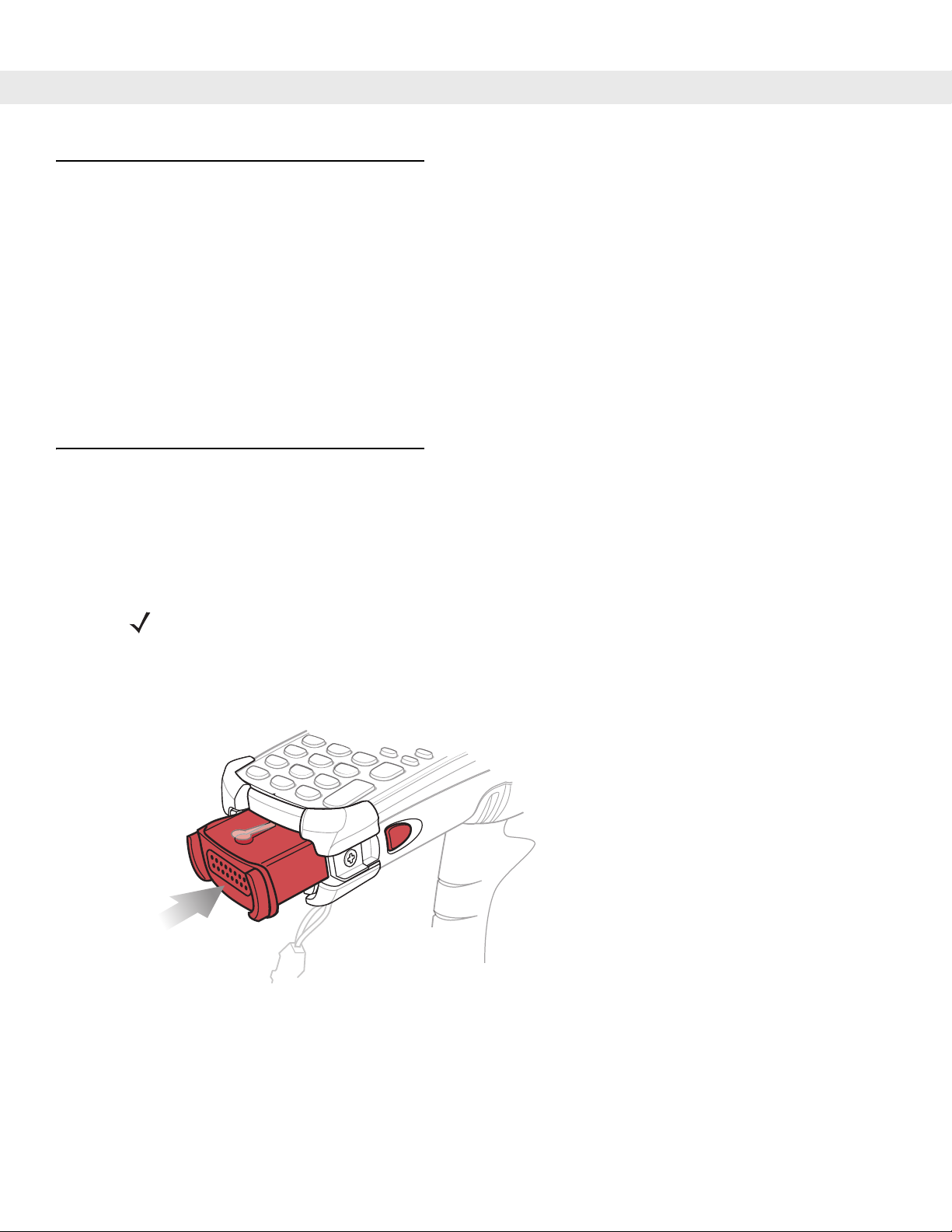
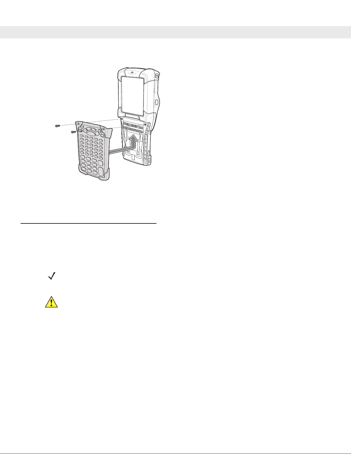
Keypad Removal
1. Press the Power button to suspend the mobile computer.
2. Remove the two keypad screws. Slide the keypad down and lift up.
Accessories 3 - 3
CAUTION Do not remove the keypad while the mobile computer is on and do not operate the mobile computer
with the keypad detached. Follow proper Electro-Static Discharge (ESD) precautions to avoid
damaging the MMC and SD card. Proper ESD precautions include, but are not limited to, working on
an ESD mat and ensuring that the operator is properly grounded.
MC9090 keypads are not interchangeable with MC9090-G RFID keypad.
Screws
Keypad
Multi Media Card Holder
Figure 3-1
3. Replace the keypad and re-attach using the two screws.
Removing the Keypad
CAUTION Do not apply more than 4 in-lbs of torque when tightening the keypad screws.
Page 54
3 - 4 MC9090-G RFID User Guide
Figure 3-2
4. Perform a cold boot.
Installing the Keypad
See
Resetting the Mobile Computer on page 2-18
Multi Media Card (MMC) / Secure Device (SD) Card
The MMC provides secondary non-volatile storage. The MMC is located under the keyp ad (see Figure 3-1 on
page 3-3).
NOTE SD cards are inter-operable with MMC cards and can also be used in MC909X mobile computers.
CAUTION Do not remove the keypad while the mobile computer is on and do not operate the mobile computer
with the keypad detached. Follow proper ESD precautions to avoid damaging the MMC/SD. Proper
ESD precautions include, but are not limited to, working on an ESD mat and ensuring that the
operator is properly grounded.
To insert the MMC/SD:
1. Suspend the mobile computer.
2. Remove the two keypad screws and slide the keypad down and lift off (see Figure 3-1 on page 3-3).
.
3. Lift the MMC/SD retaining door.
4. Position the MMC/SD, with the contacts down, into the MMC/SD holder. The MMC/SD corner notch fits into
the holder only one way. Snap the retaining door closed.
Page 55
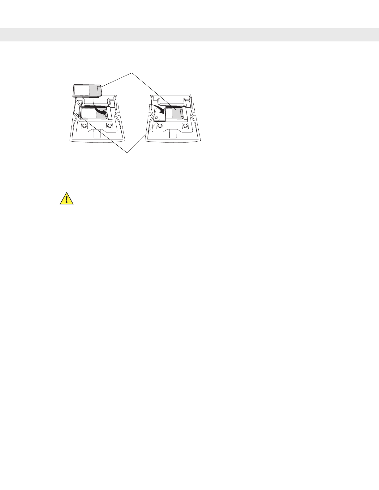
MMC/SD
MMC/SD Retaining Door
Accessories 3 - 5
Figure 3-3
Inserting the MMC/SD
CAUTION Do not apply more than 4 in-lbs of torque when tightening the keypad screws.
5. Replace the keypad and re-attach using the two screws (see Figure 3-2 on page 3-4).
Page 56

3 - 6 MC9090-G RFID User Guide
Page 57

Chapter 4
Chapter 4
Chapter 4
Maintenance & Troubleshooting
Introduction
This chapter includes instructions on cleaning and storing the mobile computer, and provides troubleshooting
solutions for potential problems during mobile computer operation.
Maintaining the Mobile Computer
For trouble-free service, observe the following tips when using the mobile computer:
•
Protect the mobile computer from temperature extremes. Do not leave it on the dashboard of a car on a
hot day, and keep it away from heat sources.
•
Do not store or use the mobile computer in any location that is extremely dusty, damp, or wet.
Maintenance & Troubleshooting
•
Use a soft lens cloth to clean the mobile computer . If the surface of the mobile computer screen becomes
soiled, clean it with a soft cloth moistened with a diluted window-cleaning solution.
•
Periodically replace the rechargeable Li-ion battery to ensure maximum battery life and product
performance. Battery life depends on individual usage patterns.
•
Take care not to scratch the screen of the mobile computer. When working with the mobile computer, use
the supplied stylus or plastic-tipped pens intended for use with a touch-sensitive screen. Never use an
actual pen or pencil or other sharp object on the surf ace of the mobile computer screen.
•
The touch-sensitive screen of the mobile computer contains glass. Take care not to drop the mobile
computer or subject it to strong impact.
Page 58

4 - 2 MC9090-G RFID User Guide Suppliment
Accessories
The MC909X User Guide, P/N: 72E-72215-xx provides the troubleshooting information applicable to the
following MC9090-G RFID mobile computer accessories:
•
Bluetooth Connection
•
Four Slot Charge Only Cradle
•
Four Slot Ethernet Cradle
•
Four Slot Spare Battery Charger
•
Single Slot Serial/USB Cradle
•
Cable Adapter Module
•
Magnetic Stripe Reader
•
Modem Module
Page 59

Troubleshooting
Mobile Computer
Maintenance & Troubleshooting 4 - 3
Table 4-1
Mobile computer does
not turn on.
Rechargeable
lithium-ion battery did
not charge.
Cannot see
characters on display.
During data
communication, no
data was transmitted,
or transmitted data
was incomplete.
Troubleshooting the Mobile Computer
Problem Cause Solution
Lithium-ion battery
not charged.
Lithium-ion battery
not installed
properly.
System crash. Perform a warm boot. If the mobile computer still does not turn
Battery failed. Replace battery. If the mobile computer still does not operate,
Mobile computer
removed from
cradle while battery
was charging.
Mobile computer
not powered on.
Mobile computer
removed from
cradle or unplugged
from host computer
during
communication.
Charge or replace the lithium-ion battery in the mobile
computer.
Ensure battery is installed properly. See
Removing the Main Battery on page 1-4
on, perform a cold boot. See
on page 2-18
try a warm boot, then a cold boot. See
Computer on page 2-18
Insert mobile computer in cradle and begin charging. The
lithium-ion battery requires less than four hours to recharge
fully.
Press the
Replace the mobile computer in the cradle, or reattach the
Synchronization cable and re-transmit.
.
Power
button.
Resetting the Mobile Computer
.
Installing and
.
Resetting the Mobile
Incorrect cable
configuration.
Communication
software was
incorrectly installed
or configured.
No sound is audible. Volume setting is
low or turned off.
See the System Administrator.
Perform setup. Refer to the MC909X Integrator Guide for
details.
Ensure that Microsoft ActiveSync 4.1 or greater is installed on
the host computer.
Adjust volume.
Page 60

4 - 4 MC9090-G RFID User Guide Suppliment
Table 4-1
Troubleshooting the Mobile Computer (Continued)
Problem Cause Solution
Mobile computer
turns itself off.
Tapping the window
buttons or icons does
not activate the
corresponding
feature.
A message appears
stating that the mobile
computer memory is
full.
Mobile computer is
inactive.
The mobile computer turns off after a period of inactivity. If the
mobile computer is running on battery power , t his period can be
set to 30 sec., 1, 2, 3, 4, 5 or 6 minutes. If the mobile computer
is running on external power, this period can be set to 1, 2, 3, 5,
10, 15 and 30 minutes.
For Windows Mobile 5.0 devices, Check the power settings by
tapping
Start
>
Settings
>
System
tab >
Power
icon >
tab.
Change the setting if a longer delay is required before the
automatic shutoff feature activates.
Battery is depleted. Replace the battery.
Battery is not
inserted properly.
LCD screen not
Insert the battery properly (see
Main Battery on page 1-4
).
Re-calibrate the screen.
Installing and Removing the
aligned correctly.
The system is hung. Warm boot the system. To perform a warm boot (see
Too many files
stored on the
the Mobile Computer on page 2-18
Delete unused memos and records. Save these records on the
host computer.
).
mobile computer.
Too many
applications
installed on the
mobile computer.
If additional applications have been installed on the mobile
computer, remove them to recover memory.
For Windows Mobile 5.0 devices, tap
tab >
Remove Programs
icon.
Select the unused program and tap
Start
>
Remove.
Settings
Advanced
Resetting
>
System
Page 61

Maintenance & Troubleshooting 4 - 5
Table 4-1
The mobile computer
does not accept scan
input.
Troubleshooting the Mobile Computer (Continued)
Problem Cause Solution
Scanning
application is not
loaded.
Unreadable bar
code.
Distance between
exit window and bar
code is incorrect.
Mobile computer is
not programmed for
the bar code.
Mobile computer is
not programmed to
generate a beep.
Battery is low. If the scanner stops emitting a laser beam when the trigger is
Verify that the unit is loaded with a scanning application. See
the System Administrator.
Ensure the symbol is not defaced.
Ensure mobile computer is within proper scanning range.
Ensure the mobile computer is programmed to accept the type
of bar code being scanned.
If a beep on a good decode is expected and a beep is not
heard, check that the application is set to generate a beep on
good decode.
pressed, check the battery level. When the battery is low, the
scanner shuts off before the mobile computer low battery
condition notification.
Note: If the scanner is still not reading symbols, contact the
distributor or Symbol Technologies.
WLAN connection is
lost when the mobile
computer is
connected to a host
computer using
ActiveSync.
Microsoft security
feature prevents
connection to two
separate networks.
Disconnect from the WLAN network prior to connecting to a
host computer using ActiveSync.
Page 62

4 - 6 MC9090-G RFID User Guide Suppliment
Page 63

Appendix A
Appendix A Specifications
Technical Specifications
The following tables summarize the mobile computer’s intended operating environment and general technical
hardware specifications.
Mobile Computer
The following table summarizes the mobile computer’s intended operating environment.
Specifications
Table A-1
Physical and Environmental Characteristics
Dimensions 9.1 in. L x 3.6 in. W x 7.6 in. H
Weight 25 oz.(includes battery, scanner and radio)
Keyboard 28-key; 43-key; 53-key
Display 3.8 in. 1/4 VGA Color
Power Removable, rechargeable 7.2 V Lithium Ion 2200 mAh battery pack, 15.8 watt
Performance Characteristics
CPU XScale Bulverde PXA270 processor at 624MHz
Operating System Microsoft Windows Mobile 5.0 Premium Edition
Memory (RAM/ROM) Windows Mobile: 64MB/128MB
Expansion SD/MMC Card
Application Development PSDK, DCP and SMDK available through Symbol Developer Zone Web Site
Technical Specifications
Item MC9090-G RFID
23.1 cm L x 9.1 cm H x 19.3 cm H
Terminal Emulation (5250, 3270, VT)
hours
Data Capture Options Omni-directional 1D and 2D imaging engine reads symbologies and captures
grayscale images and signatures with intuitive laser aiming.
Page 64

A - 2 MC9090-G RFID User Guide Suppliment
Table A-1
User Environment
Technical Specifications (Continued)
Item MC9090-G RFID
Operating Temperature -4°F to 122°F (-20°C to 50°C)
Storage Temperature -25°F to 160°F (-40°C to 70°C)
Battery Charging Temperature 32 °F to 104 °F (0 °C to +40 °C) ambient temperature range.
Humidity 5% to 95% non condensing
Drop Specification Multiple 6 ft.(1.8m) drops to concrete across operating temperature range
Tumble 2,000 one-meter tumbles at room temperature (4,000 hits)
Environmental Sealing IP64 (electronic enclosure)
ESD +/-15kVdc air discharge
+/-8kVdc direct discharge
+/-8kVdc indirect discharge
Wireless Data Communications
WLAN Symbol 802.11b/g
Output Power 100mW U.S. and International
Data Rate 802.11b: 11Mb per second
802.11g: 54Mb per second
Antenna Internal
Frequency Range: 802.11b: 2.4 GHz; country-dependent
802.11g: 2.4 GHz; country-dependent
Bluetooth Bluetooth Version 1.2 with BTExplorer (manager) included
Peripherals and Accessories
Cradles Single-slot and 4-slot cradles available
Printers Supports extensive line of Symbol approved printers, cables and accessories
Charger 4-Slot universal battery charger
Other Accessories Cable Adapter Module; Magnetic Stripe Reader; Modem; Full set of holsters
In accordance with the SymbolPlus partner program
Regulatory
Electrical Safety Certified to UL60950-1, CSA C22.2 No. 60950-1, EN60950-1, IEC 60950-1
RF & EMC FCC PArt 2 (SAR), FCC Part 15, RSS210; EN 300 328 & EN 301 487,
EN55022, EN55024
Page 65

Appendix A: Specifications A - 3
Table A-2
Data Capture Options
Item Description
Imaging Decode Capability Code 39 Code 128 Code 93
Codabar Code 11 Interleaved 2 of 5
Discrete 2 of 5 MSI EAN-8
EAN-13 UPCA UPCE
UPC/EAN supplementals Coupon Code Trioptic 39
Webcode TLC39 Composite AB
Composite C Micro PDF-417 PDF-417
Macro PDF-417 (Macro) Micro PDF-417 QR Code
RSS Expanded RSS Limited RSS-14
Data Matrix Maxi Code US Postnet*
US Planet UK 4-state Australian 4-state
Canadian 4-state Japanese 4-state Dutch Kix
*To be supported at a later date. Go to http://software.symbol.com/ for a list of
the latest supported symbologies.
Modem Module
Table A-3
Environmental Parameters and Technical Hardware Specifications
Item Description
Asynchronous character
Up to 10 bits, including data, start, stop, and parity bits
format
Asynchronous data rates Transmission rate fallback through 300 bps
Chipset Conexant SCM
Compatible public switched
RJ11
network jacks
Dialing capability Tone and rotary pulse
Line requirements Public switched telephone network (PSTN) including international
connections
Operating environment Altitude: up to 20,000 ft.
Humidity: 10% to 90% non-condensing
Operating temperature
Operating: 32
Storage: -4
o
to 122oF / 0o to 50oC
o
to 149oF / -20o to 65oC
Operating modes Asynchronous, full duplex, automatic and manual call originate
Page 66

A - 4 MC9090-G RFID User Guide Suppliment
9
Table A-3
Performance Line speed up to 33,600 bps
Current consumption 100 mA active
Pulse dialing rate
(except where prohibited
under TBR-21 rules)
Ringer equivalence 0.1 dBm
Standards & protocols Bell 103, Bell 212A, Hayes AT command set, and ITU Vs. 17, 21, 22 A & B,
Tone detected Dial, busy, ring back, modem answer tones.
AC Adapter 9V, 2 amp regulated AC/DC adapter allows unlimited modem use. Do NOT
Environmental Parameters and Technical Hardware Specifications (Continued)
Item Description
HHC to modem speed (DTE speed) up to 57,600 bps
V.42bis data compression
V.42 LAPM error correction
<10 mA sleep
10 pulses per second
Pulse dialing duty cycle: 39/61% (US) make-to-break ratio
22bis, 23, 25bis, 27 ter, 29, 32, 32bis, 42bis
Blind dialing based on time-out periods available for incompatible tones.
substitute an AC adapter; using an incorrect AC power supply causes
electrical damage to the mobile computer and voids warranty.
Mobile Computer Pin-Outs
17
1
Figure A-1
Table A-4
PIN Number Signal Name Function
1 USB_GND USB
2 USB_D_PLUS USB
3 TXD RS232C
4 RXD RS232C
5 DCD RS232C
6 RTS RS232C
Pin Locations
Pin-Outs
8
Page 67

Appendix A: Specifications A - 5
Table A-4
PIN Number Signal Name Function
7 DSR RS232C
8 GND Ground, 2.5A max.
9 RI RS232C
10 CRADLE_DET Grounded by cradle when in cradle
11 DTR RS232C
12 Not connected Not connected
13 POWER_IN 12V, 2.5A max
14 CTS RS232C
15 USB_5V_DET USB
16 USB_D_MINUS USB
17 EXT_PWR_OUT 3.3V @500mA
Pin-Outs (Continued)
Accessory CAM and MSR Pin-Outs
Figure A-2
Table A-5
Pin Signal
1 USB_5V_DET
2 USB_D_MINUS
3 USB_D_PLUS
4GND
5GND
6 PWR_EXT_OUT
7 CRADLE_DET*
CAM and MSR Serial Connector
CAM and MSR Serial Connector Pin-outs
Page 68

A - 6 MC9090-G RFID User Guide Suppliment
Table A-5
8DSR
9DCD
10 TXD
11 CTS
12 DTR
13 RI
14 RTS
15 RXD
CAM and MSR Serial Connector Pin-outs
Pin Signal
Page 69

Appendix B
Keypad Special Keys
Appendix B
Introduction
This appendix contains the keypad functions/special characters for the keypad. Each function/special
character is included in the table along with how the function/special character is generated.
Keypad
The mobile computer is available with the following keypad:
•
53-key RFID keypad
The keypads contain a Power button, application keys, scroll keys and function keys. The keypad is
color-coded to indicate the alternate function key (blue) values and the alternate ALPHA key (orange) values.
See Table B-1 for the special character generation. Characters can also be generated using the keyboard input
panel.
Table B-1
Special Character Description 53-Key Keypad
Keypad Special Keys
Special Character Generation Map
[
]
/
\
= Equal sign
;Semi-colon
`
,
.
!
@
# Pound sign
Open square bracket
Close square bracket
Forward slash
Backslash
Apostrophe
Comma
Period
Exclamation point
At sign
Blue Key Blue Key Blue Key -
Blue Key Blue Key Blue Key Blue Key Blue Key Blue Key Blue Key -
SHIFT
SHIFT
SHIFT
E
F
L
,
V
G
W
R
J
A
B
-
1
-
2
-
3
Page 70

B - 2 MC9090-G RFID User Guide Suppliment
Table B-1
Special Character Description 53-Key Keypad
$
%
^
&
*
(
)
‘
“
+
-
Special Character Generation Map (Continued)
Dollar sign
Percent sign
Carat
Ampersand
Asterisk
Open parenthesis
Close parenthesis
Single quote
Double quote)
Plus sign
Dash
SHIFT
-
SHIFT
-
SHIFT
-
SHIFT
-
Blue Key -
SHIFT
- Blue Key - U,
SHIFT
-
SHIFT
-
SHIFT
-
Blue Key -
SHIFT
- Blue Key -
Blue Key -
SHIFT
- Blue Key - S,
SHIFT
- Blue Key -
Blue Key Blue Key -
SHIFT
- Blue Key -
4
5
6
7
8
9
0
U
,
C
S
,
N
,
T
,
C
W
T
:
<
>
?
_
Underscore
{
}
~
|
Colon
Less than sign
Greater than sign
Question mark
Open curly bracket
Close curly bracket
Tilde
Pipe
SHIFT
SHIFT SHIFT
SHIFT -
SHIFT
SHIFT
SHIFT
SHIFT
SHIFT
SHIFT
- Blue Key Blue Key -
- Blue Key Blue Key - L,
- Blue Key -
- Blue Key -
- Blue Key -
- Blue Key -
- Blue Key
- Blue Key -
R
A
B
V
N
E
F
- J
G
Page 71

Appendix C
Regulatory
Appendix C
Regulatory
Introduction
This appendix contains the accessory power supply regulatory compliance statements.
Accessory Power Supply Regulatory Compliance
Table C-1
Single Slot Serial/USB Cradle
Power Supply
Magnetic Stripe Reader (MSR)
Cable Adapter Module (CAM)
Accessory Power Supplies, Regulatory Compliance Statements
Accessory Power Supplies Regulatory Compliance Statements
Use only a Symbol-approved power supply output rated 12 VDC and
minimum 3.3 A. The power supply is certified to EN60950 with SELV
outputs. Use of alternative power supply will invalidate any approval given
to this device and may be dangerous.
Benutzen Sie nur eine von Symbol Technologies genehmigte
Stromversorgung mit einer Ausgangsleistung von 12 V (Gleichstrom) und
mindestens 3.3 A. Die Stromversorgung ist nach EN60950 für die
Verwendung in SELV-Stromkreisen zertifiziert. Bei Verwendung eines
anderen Netzteils werden alle für das Gerät gewährten Genehmigungen
außer Kraft gesetzt, und der Betrieb kann gefährlich sein.
Four Slot Charge Only Cradle
Power Supply
Four Slot Ethernet Cradle Power
Supply
Use only a Symbol-approved power supply output rated 12 VDC and
minimum 9 A. The power supply is certified to EN60950 with SEL V output s.
Use of alternative power supply will invalidate any approval given to this
device and may be dangerous.
Benutzen Sie nur eine von Symbol Technologies genehmigte
Stromversorgung mit einer Ausgangsleistung von 12 V (Gleichstrom) und
mindestens 9 A. Die Stromversorgung ist nach EN60950 für die
Verwendung in SELV-Stromkreisen zertifiziert. Bei Verwendung eines
anderen Netzteils werden alle für das Gerät gewährten Genehmigungen
außer Kraft gesetzt, und der Betrieb kann gefährlich sein.
Page 72

C - 2 MC9090-G RFID User Guide Suppliment
Table C-1
Universal Battery Charger (UBC)
Adapter Power Supply
Four Slot Spare Battery Charger
Power Supply
Accessory Power Supplies, Regulatory Compliance Statements
Accessory Power Supplies Regulatory Compliance Statements
Use only a Symbol-approved power supply output rated 15 VDC and
minimum 1.5 A. The power supply is certified to EN60950 with SELV
outputs. Use of alternative power supply will invalidate any approval given
to this device and may be dangerous.
Benutzen Sie nur eine von Symbol Technologies genehmigte
Stromversorgung mit einer Ausgangsleistung von 15 V (Gleichstrom) und
mindestens 1.5 A. Die Stromversorgung ist nach EN60950 für die
Verwendung in SELV-Stromkreisen zertifiziert. Bei Verwendung eines
anderen Netzteils werden alle für das Gerät gewährten Genehmigungen
außer Kraft gesetzt, und der Betrieb kann gefährlich sein.
Use only a Symbol-approved power supply output rated 15 VDC and
minimum 5 A. The power supply is certified to E N60950 with SELV outputs.
Use of alternative power supply will invalidate any approval given to this
device and may be dangerous.
Benutzen Sie nur eine von Symbol Technologies genehmigte
Stromversorgung mit einer Ausgangsleistung von 15 V (Gleichstrom) und
mindestens 5 A. Die Stromversorgung ist nach EN60950 für die
Verwendung in SELV-Stromkreisen zertifiziert. Bei Verwendung eines
anderen Netzteils werden alle für das Gerät gewährten Genehmigungen
außer Kraft gesetzt, und der Betrieb kann gefährlich sein.
Page 73

IndexIndex
Index
Numerics
2-D bar codes . . . . . . . . . . . . . . . . . . . . . . . . . . . . . 2-14
53-key keypad . . . . . . . . . . . . . . . . . . . . . . . . . . . . . . 2-9
A
accessories . . . . . . . . . . . . . . . . . . . . . . . . . . . . . . . . 1-3
accessory keyboard . . . . . . . . . . . . . . . . . . . . . . 1-3
auto charge cable . . . . . . . . . . . . . . . . . . . . . . . . 3-2
cables . . . . . . . . . . . . . . . . . . . . . . . . . . . . . . 1-3, 3-2
CAM . . . . . . . . . . . . . . . . . . . . . . . . . . . . . . . 1-3, 3-2
DEX cable . . . . . . . . . . . . . . . . . . . . . . . . . . . 1-3, 3-2
four slot charge only cradle . . . . . . . . . . . . . 1-3, 3-1
four slot Ethernet/USB cradle . . . . . . . . . . . . 1-3, 3-1
four slot spare battery charger . . . . . . . . . . . . . . 1-3
holster, quick release . . . . . . . . . . . . . . . . . . . . . 1-3
keypad . . . . . . . . . . . . . . . . . . . . . . . . . . . . . . . . 3-1
magnetic stripe reader . . . . . . . . . . . . . . . . . 1-3, 3-2
modem module . . . . . . . . . . . . . . . . . . . . . . . . . . 1-3
multi media card . . . . . . . . . . . . . . . . . . . . . . . . . 1-3
printer cable . . . . . . . . . . . . . . . . . . . . . . . . . 1-3, 3-2
serial cradle . . . . . . . . . . . . . . . . . . . . . . . . . . . . 1-3
serial/USB cradle . . . . . . . . . . . . . . . . . . . . . . . . 3-1
shelf slide . . . . . . . . . . . . . . . . . . . . . . . . . . . . . . 1-3
SMDK . . . . . . . . . . . . . . . . . . . . . . . . . . . . . . . . . 1-3
spare battery . . . . . . . . . . . . . . . . . . . . . . . . . . . . 1-3
stylus . . . . . . . . . . . . . . . . . . . . . . . . . . . . . . . . . 1-3
UBC adapter . . . . . . . . . . . . . . . . . . . . . . . . . . . . 1-3
USB charger cable . . . . . . . . . . . . . . . . . . . . 1-3, 3-2
wall mounting bracket . . . . . . . . . . . . . . . . . . . . . 1-3
accessory keyboard . . . . . . . . . . . . . . . . . . . . . . . . . 1-3
ActiveSync
icon . . . . . . . . . . . . . . . . . . . . . . . . . . . . . . . . . . . 2-3
aiming options
aiming pattern . . . . . . . . . . . . . . . . . . . . . . . . . . 2-14
aiming the imager . . . . . . . . . . . . . . . . . . . . . . . . . . 2-14
aligning screen . . . . . . . . . . . . . . . . . . . . . . . . . . . . . 1-8
attaching MC9090-G strap . . . . . . . . . . . . . . . . . . . 1-10
auto charge cable . . . . . . . . . . . . . . . . . . . . . . . . . . . 3-2
B
backlight . . . . . . . . . . . . . . . . . . . . . . . . . . . . . . . . . . 2-12
backlight intensity . . . . . . . . . . . . . . . . . . . . . . . . . . . 2-12
backup battery
charging . . . . . . . . . . . . . . . . . . . . . . . . . . . . . . . . 1-5
bar codes
two dimensional . . . . . . . . . . . . . . . . . . . . . . . . . 2-14
battery
backup charging . . . . . . . . . . . . . . . . . . . . . . . . . 1-5
charging . . . . . . . . . . . . . . . . . . . . . . . . . . . . . . . . 1-5
check status . . . . . . . . . . . . . . . . . . . . . . . . . . . . 1-8
installing . . . . . . . . . . . . . . . . . . . . . . . . . . . . . . . 1-4
removing . . . . . . . . . . . . . . . . . . . . . . . . . . . . . . . 1-7
battery charging temperature . . . . . . . . . . . . . . . . . . . A-2
battery management . . . . . . . . . . . . . . . . . . . . . . . . 1-10
beeper volume . . . . . . . . . . . . . . . . . . . . . . . . . . . . . 2-12
Bluetooth . . . . . . . . . . . . . . . . . . . . . . . . . . . . 1-12, 2-19
bluetooth
communicating icon . . . . . . . . . . . . . . . . . . . . . . . 2-3
disabled icon . . . . . . . . . . . . . . . . . . . . . . . . . . . . 2-3
enabled icon . . . . . . . . . . . . . . . . . . . . . . . . . . . . 2-3
boot
cold . . . . . . . . . . . . . . . . . . . . . . . . . . 1-8, 2-13, 2-18
warm . . . . . . . . . . . . . . . . . . . . . . . . . . . . 2-13, 2-18
bullets . . . . . . . . . . . . . . . . . . . . . . . . . . . . . . . . . . . . . vii
buttons
power . . . . . . . . . . . . . . . . . . . . . . . . . . . . . . . . . 2-13
C
Cable Adapter Module . . . . . . . . . . . . . . . . . . . . 1-3, 3-2
cables . . . . . . . . . . . . . . . . . . . . . . . . . . . . . . . . 1-3, 3-2
auto charge cable . . . . . . . . . . . . . . . . . . . . . . . . 3-2
DEX cable . . . . . . . . . . . . . . . . . . . . . . . . . . 1-3, 3-2
printer cable . . . . . . . . . . . . . . . . . . . . . . . . . 1-3, 3-2
USB charger . . . . . . . . . . . . . . . . . . . . . . . . 1-3, 3-2
calibrating screen . . . . . . . . . . . . . . . . . . . . . . . . . . . . 1-8
CAM . . . . . . . . . . . . . . . . . . . . . . . . . . . . . . . . . . 1-3, 3-2
changing the power settings . . . . . . . . . . . . . . . . . . 1-11
characters, special . . . . . . . . . . . . . . . . . . . . . . . . . . .B-1
Page 74

Index - 2 MC9090-G RFID User Guide Suppliment
charging
spare batteries . . . . . . . . . . . . . . . . . . . . . . . . . . 1-6
charging batteries . . . . . . . . . . . . . . . . . . . . . . . . . . . 1-5
charging spare batteries . . . . . . . . . . . . . . . . . . . . . . 1-6
cleaning . . . . . . . . . . . . . . . . . . . . . . . . . . . . . . . . . . . 4-1
cold boot . . . . . . . . . . . . . . . . . . . . . . . . . 1-8, 2-13, 2-18
command bar
icons . . . . . . . . . . . . . . . . . . . . . . . . . . . . . . .2-2, 2-3
command bar icons . . . . . . . . . . . . . . . . . . . . . . . . . . 2-3
configuration . . . . . . . . . . . . . . . . . . . . . . . . . . . . . . . 1-4
conventions
notational . . . . . . . . . . . . . . . . . . . . . . . . . . . . . . . vii
CPU . . . . . . . . . . . . . . . . . . . . . . . . . . . . . . . . . . . . . . A-1
cradles
four slot charge only . . . . . . . . . . . . . . . . . . .1-3, 3-1
four slot Ethernet/USB . . . . . . . . . . . . . . . . .1-3, 3-1
serial . . . . . . . . . . . . . . . . . . . . . . . . . . . . . . . . . . 1-3
serial/USB . . . . . . . . . . . . . . . . . . . . . . . . . . . . . . 3-1
D
data capture
adjusting the distance . . . . . . . . . . . . . . . . . . . . 2-16
imager operational modes
decode mode . . . . . . . . . . . . . . . . . . . . . . . 2-14
image capture mode . . . . . . . . . . . . . . . . . . 2-14
pick list mode . . . . . . . . . . . . . . . . . . . . . . . 2-14
imaging . . . . . . . . . . . . . . . . . . . . . . . . . . . . . . . 2-14
indicator . . . . . . . . . . . . . . . . . . . . . . . . . . . . . . 2-16
scan angle . . . . . . . . . . . . . . . . . . . . . . . . . . . . . 2-15
scan range . . . . . . . . . . . . . . . . . . . . . . . . . . . . 2-15
scanning . . . . . . . . . . . . . . . . . . . . . . . . . . . . . . 2-15
two dimensional bar codes . . . . . . . . . . . . . . . . 2-14
DCP for MC9090w . . . . . . . . . . . . . . . . . . . . . . . . . . . .viii
Device Configuration Package for MC9090w . . . . . . .viii
DEX cable . . . . . . . . . . . . . . . . . . . . . . . . . . . . . .1-3, 3-2
dimensions . . . . . . . . . . . . . . . . . . . . . . . . . . . . . . . . A-1
display . . . . . . . . . . . . . . . . . . . . . . . . . . . . . . . . . . . . A-1
display backlight
saving power . . . . . . . . . . . . . . . . . . . . . . . . . . . 1-11
display backlight intensity . . . . . . . . . . . . . . . . . . . . 2-12
drop specification . . . . . . . . . . . . . . . . . . . . . . . . . . . . A-2
F
flash card . . . . . . . . . . . . . . . . . . . . . . . . . . . . . . 1-3, 3-4
four slot charge only . . . . . . . . . . . . . . . . . . . . . . 1-3, 3-1
four slot Ethernet/USB . . . . . . . . . . . . . . . . . . . . 1-3, 3-1
four slot spare battery charger . . . . . . . . . . . . . . . . . . 1-3
frequency-hopping . . . . . . . . . . . . . . . . . . . . . . . . . . 2-19
G
getting started . . . . . . . . . . . . . . . . . . . . . . . . . . . . . . . 1-4
H
hard reset . . . . . . . . . . . . . . . . . . . . . . . . .1-8, 2-13, 2-18
headset . . . . . . . . . . . . . . . . . . . . . . . . . . . . . . . . . . .2-13
holster . . . . . . . . . . . . . . . . . . . . . . . . . . . . . . . . . . . . .1-3
humidity . . . . . . . . . . . . . . . . . . . . . . . . . . . . . . . . . . .A-2
I
icons
ActiveSync . . . . . . . . . . . . . . . . . . . . . . . . . . . . . .2-3
battery . . . . . . . . . . . . . . . . . . . . . . . . . . . . . . . . .2-2
bluetooth communicating . . . . . . . . . . . . . . . . . . . 2-3
bluetooth disabled . . . . . . . . . . . . . . . . . . . . . . . .2-3
bluetooth enabled . . . . . . . . . . . . . . . . . . . . . . . .2-3
connectivity . . . . . . . . . . . . . . . . . . . . . . . . . . . . .2-2
e-mail . . . . . . . . . . . . . . . . . . . . . . . . . . . . . . . . . .2-2
instant message . . . . . . . . . . . . . . . . . . . . . . . . . .2-2
phone edition . . . . . . . . . . . . . . . . . . . . . . . . . . . . 2-2
speaker . . . . . . . . . . . . . . . . . . . . . . . . . . . . . . . .2-2
status . . . . . . . . . . . . . . . . . . . . . . . . . . . . . . 2-2, 2-3
wireless applications . . . . . . . . . . . . . . . . . . . . . . 2-3
WWAN . . . . . . . . . . . . . . . . . . . . . . . . . . . . . . . . .2-2
imager. See data capture, imaging, imagersample
imaging . . . . . . . . . . . . . . . . . . . . . . . . . . . . . . . . . . . 2-14
information, service . . . . . . . . . . . . . . . . . . . . . . . . . . viii
installing main battery . . . . . . . . . . . . . . . . . . . . . . . . .1-4
E
electrical safety . . . . . . . . . . . . . . . . . . . . . . . . . . . . . A-5
electro-static discharge
email notification icon . . . . . . . . . . . . . . . . . . . . . . . . 2-2
ESD . . . . . . . . . . . . . . . . . . . . . . . . . . . . . . . . . . .3-2, 3-4
Page 75

Index - 3
K
key descriptions
53-key . . . . . . . . . . . . . . . . . . . . . . . . . . . . . . . . 2-10
special functions . . . . . . . . . . . . . . . . . . . . . . . . 2-12
keyboard . . . . . . . . . . . . . . . . . . . . . . . . . . . . . . . . . . A-1
keypad . . . . . . . . . . . . . . . . . . . . . . . . . . . . . . . . . . . 3-1
53-key . . . . . . . . . . . . . . . . . . . . . . . . . . . . . . . . . B-1
keypad backlight
saving power . . . . . . . . . . . . . . . . . . . . . . . . . . 1-11
keypad functions . . . . . . . . . . . . . . . . . . . . . . . . . . . . B-1
keypads
53-key . . . . . . . . . . . . . . . . . . . . . . . . . . . . . . . . . 2-9
special functions . . . . . . . . . . . . . . . . . . . . . . . . 2-12
types . . . . . . . . . . . . . . . . . . . . . . . . . . . . . . . 2-8, 3-1
L
laser safety . . . . . . . . . . . . . . . . . . . . . . . . . . . . . . . . A-5
laser scanning
See data capture . . . . . . . . . . . . . . . . . . . . . . . 2-14
LED Indicator Bar . . . . . . . . . . . . . . . . . . . . . . . . . . . 2-8
lithium-ion battery . . . . . . . . . . . . . . . . . . . . . . . . . . . 1-2
locking the mobile computer . . . . . . . . . . . . . . . . . . . 2-7
P
parts of the mobile computer . . . . . . . . . . . . . . . . . . . 1-2
pin-outs
accessory . . . . . . . . . . . . . . . . . . . . . . . . . . . . . . A-8
mobile computer . . . . . . . . . . . . . . . . . . . . . . . . . A-7
power button . . . . . . . . . . . . . . . . . . . . . . . . . . . . . . 2-13
power settings . . . . . . . . . . . . . . . . . . . . . . . . . . . . . 1-11
power supply regulatory compliance . . . . . . . . . . . . .C-1
printer cable . . . . . . . . . . . . . . . . . . . . . . . . . . . . 1-3, 3-2
Q
quick release holster . . . . . . . . . . . . . . . . . . . . . . . . . 1-3
R
radios . . . . . . . . . . . . . . . . . . . . . . . . . . . . . . . . . . . . 1-12
regulatory compliance, power supply . . . . . . . . . . . . .C-1
removing main battery . . . . . . . . . . . . . . . . . . . . . . . . 1-7
reset
hard . . . . . . . . . . . . . . . . . . . . . . . . . . 1-8, 2-13, 2-18
soft . . . . . . . . . . . . . . . . . . . . . . . . . . . . . . 2-13, 2-18
resetting . . . . . . . . . . . . . . . . . . . . . . . . . . . . . . . . . . 2-18
M
magnetic stripe reader . . . . . . . . . . . . . . . . . . . . 1-3, 3-2
main battery
charging . . . . . . . . . . . . . . . . . . . . . . . . . . . . 1-4, 1-5
installing . . . . . . . . . . . . . . . . . . . . . . . . . . . . . . . 1-4
maintenance . . . . . . . . . . . . . . . . . . . . . . . . . . . . . . . 4-1
MDM9000 . . . . . . . . . . . . . . . . . . . . . . . . . . . . . . . . . 1-3
memory . . . . . . . . . . . . . . . . . . . . . . . . . . . . . . . . . . . A-2
MMC . . . . . . . . . . . . . . . . . . . . . . . . . . . . . . . . . . 1-3, 3-4
mobile computer
power on . . . . . . . . . . . . . . . . . . . . . . . . . . . . . . 2-13
starting . . . . . . . . . . . . . . . . . . . . . . . . . . . . . . . . 1-8
mobile computer configuration . . . . . . . . . . . . . . . . . 1-4
modem module . . . . . . . . . . . . . . . . . . . . . . . . . . . . . 1-3
MSR . . . . . . . . . . . . . . . . . . . . . . . . . . . . . . . . . . 1-3, 3-2
multi media card . . . . . . . . . . . . . . . . . . . . . . . . . 1-3, 3-4
O
operating environment, mobile computer . . . . . . . . . A-1
operating system . . . . . . . . . . . . . . . . . . . . . . . . . . . . A-2
operating temperature . . . . . . . . . . . . . . . . . . . . . . . . A-2
S
scan status . . . . . . . . . . . . . . . . . . . . . . . . . . . . . . . . 2-16
scan status See also data capture
scanning
bar codes . . . . . . . . . . . . . . . . . . . . . . . . . . . . . . 2-15
imaging . . . . . . . . . . . . . . . . . . . . . . . . . . . . . . . 2-14
LED indicators . . . . . . . . . . . . . . . . . . . . . . . . . . 2-16
See data capture . . . . . . . . . . . . . . . . . . . . . . . . 2-14
screen
calibration . . . . . . . . . . . . . . . . . . . . . . . . . . . . . . 1-8
Symbol splash window . . . . . . . . . . . . . . . . . . . . 1-8
SD . . . . . . . . . . . . . . . . . . . . . . . . . . . . . . . . . . . . . . . 3-4
SDK
See SMDK for C . . . . . . . . . . . . . . . . . . . . . . . . . 1-3
secure device card . . . . . . . . . . . . . . . . . . . . . . . . . . . 3-4
serial cradle . . . . . . . . . . . . . . . . . . . . . . . . . . . . . . . . 1-3
serial/USB cradle . . . . . . . . . . . . . . . . . . . . . . . . . . . . 3-1
service information . . . . . . . . . . . . . . . . . . . . . . . . . . . .viii
shelf slide . . . . . . . . . . . . . . . . . . . . . . . . . . . . . . . . . . 1-3
SMDK for eVC4 . . . . . . . . . . . . . . . . . . . . . . . . . . . . . .viii
soft reset . . . . . . . . . . . . . . . . . . . . . . . . . . . . 2-13, 2-18
spare batteries
charging . . . . . . . . . . . . . . . . . . . . . . . . . . . . . . . . 1-6
spare battery . . . . . . . . . . . . . . . . . . . . . . . . . . . . . . . 1-3
charging . . . . . . . . . . . . . . . . . . . . . . . . . . . . . . . . 1-6
special characters . . . . . . . . . . . . . . . . . . . . . . . . . . . B-1
specifications . . . . . . . . . . . . . . . . . . . . . . . . . . . . . . .A-1
Page 76

Index - 4 MC9090-G RFID User Guide Suppliment
starting the mobile computer . . . . . . . . . . . . . . . .1-4, 1-8
status . . . . . . . . . . . . . . . . . . . . . . . . . . . . . . . . . . . . . 2-1
status icon . . . . . . . . . . . . . . . . . . . . . . . . . . . . . . . . . 2-1
phone . . . . . . . . . . . . . . . . . . . . . . . . . . . . . . . . . 2-2
WWAN . . . . . . . . . . . . . . . . . . . . . . . . . . . . . . . . 2-2
status icons . . . . . . . . . . . . . . . . . . . . . . . . . . . . .2-2, 2-3
Windows Mobile 5.0 . . . . . . . . . . . . . . . . . . . . . . 2-1
storage temperature . . . . . . . . . . . . . . . . . . . . . . . . . A-2
strap . . . . . . . . . . . . . . . . . . . . . . . . . . . . . . . . . .1-2, 1-10
attaching to the MC9090-G . . . . . . . . . . . . . . . . 1-10
stylus . . . . . . . . . . . . . . . . . . . . . . . . . . . . . . 1-2, 1-3, 1-9
suspend . . . . . . . . . . . . . . . . . . . . . . . . . . . . . . .1-7, 2-13
Symbol Mobility Developer Kit for C . . . . . . . . . . . . . 1-3
Symbol Mobility Developer Kit for eVC4 . . . . . . . . . . .viii
symbol support center . . . . . . . . . . . . . . . . . . . . . . . . . .ix
T
taskbar . . . . . . . . . . . . . . . . . . . . . . . . . . . . . . . . . . . . 2-1
technical specifications, mobile computer . . . . . . . . . A-1
technical specifications, modem module . . . . . . . . . . A-6
troubleshooting . . . . . . . . . . . . . . . . . . . . . . . . . . . . . 4-3
bluetooth . . . . . . . . . . . . . . . . . . . . . . . . . . . . . . . 4-2
cable adapter module . . . . . . . . . . . . . . . . . . . . . 4-2
four slot charge cradle . . . . . . . . . . . . . . . . . . . . 4-2
four slot ethernet cradle . . . . . . . . . . . . . . . . . . . 4-2
four slot spare battery charger . . . . . . . . . . . . . . 4-2
magnetic stripe reader . . . . . . . . . . . . . . . . . . . . 4-2
mobile computer . . . . . . . . . . . . . . . . . . . . . .4-2, 4-3
modem module . . . . . . . . . . . . . . . . . . . . . . . . . . 4-2
single slot serial/USB cradle . . . . . . . . . . . . . . . . 4-2
turn the radios off
saving power . . . . . . . . . . . . . . . . . . . . . . . . . . . 1-12
W
wall mounting bracket . . . . . . . . . . . . . . . . . . . . . . . . . 1-3
warm boot . . . . . . . . . . . . . . . . . . . . . . . . . . . . 2-13, 2-18
weight . . . . . . . . . . . . . . . . . . . . . . . . . . . . . . . . . . . . .A-1
wireless . . . . . . . . . . . . . . . . . . . . . . . . . . . . . 1-12, 2-19
wireless status . . . . . . . . . . . . . . . . . . . . . . . . . . . . . . 2-3
WLAN . . . . . . . . . . . . . . . . . . . . . . . . . . . . . . . . . . . .1-12
U
UBC adapter . . . . . . . . . . . . . . . . . . . . . . . . . . . . . . . 1-3
unlock the mobile computer . . . . . . . . . . . . . . . . . . . . 2-7
unpacking . . . . . . . . . . . . . . . . . . . . . . . . . . . . . . . . . 1-2
USB charger . . . . . . . . . . . . . . . . . . . . . . . . . . . .1-3, 3-2
using headset . . . . . . . . . . . . . . . . . . . . . . . . . . . . . 2-13
V
volume . . . . . . . . . . . . . . . . . . . . . . . . . . . . . . . . . . . 2-12
Page 77

Page 78

Symbol Technologies, Inc.
One Symbol Plaza
Holtsville, New York 11742-1300
http://www.symbol.com
72E-89962-01
Revision A - December 2006
 Loading...