

Page 1
MC9000-G
Product Reference Guide
for Embedded Windows® CE .NET
Page 2

Page 3

MC9000-G for Embedded Windows® CE .NET
Product Reference Guide
72E-54436-08
Revision A
March 2006
Page 4

© 2006 by Symbol Technologies, Inc. All rights reserved.
No part of this publication may be reproduced or used in any form, or by any electrical or mechanical means,
without permission in writing from Symbol. This includes electronic or mechanical means, such as
photocopying, recording, or information storage and retrieval systems. The material in this manual is subject to
change without notice.
The software is provided strictly on an “as is” basis. All software, including firmware, furnished to the user is
on a licensed basis. Symbol grants to the user a non-transferable and non-exclusive license to use each
software or firmware program delivered hereunder (licensed program). Except as noted below, such license may
not be assigned, sublicensed, or otherwise transferred by the user without prior written consent of Symbol. No
right to copy a licensed program in whole or in part is granted, except as permitted under copyright law. The
user shall not modify, merge, or incorporate any form or portion of a licensed program with other program
material, create a derivative work from a licensed program, or use a licensed program in a network without
written permission from Symbol. The user agrees to maintain Symbol’s copyright notice on the licensed
programs delivered hereunder, and to include the same on any authorized copies it makes, in whole or in part.
The user agrees not to decompile, disassemble, decode, or reverse engineer any licensed program delivered to
the user or any portion thereof.
Symbol reserves the right to make changes to any software or product to improve reliability, function, or design.
Symbol does not assume any product liability arising out of, or in connection with, the application or use of any
product, circuit, or application described herein.
No license is granted, either expressly or by implication, estoppel, or otherwise under any Symbol Technologies,
Inc., intellectual property rights. An implied license only exists for equipment, circuits, and subsystems
contained in Symbol products.
Symbol, Spectrum One, and Spectrum24 are registered trademarks of Symbol Technologies, Inc. Bluetooth is a
registered trademark of Bluetooth SIG. Microsoft, Windows and ActiveSync are either registered trademarks
or trademarks of Microsoft Corporation. Other product names mentioned in this manual may be trademarks or
registered trademarks of their respective companies and are hereby acknowledged.
Symbol Technologies, Inc.
One Symbol Plaza
Holtsville, New York 11742-1300
http://www.symbol.com
Page 5

Revision History
Changes to the previous manual are listed below:
Change Date Description
-02 to -03 1/15/04 Updated Operating system to Win CE 4.2. Added new screens and menus,
Chapter 2 and Chapter 3.
Updated Chapter 6, to include Mobile Companion upgrade from version 3.9.1 to
version 3.9.2.
-03 to -04 6/18/04 Added new 28-Key keypad configurations in Chapter 2 and Appendix B.
Updated Chapter 3, to include new Bluetooth setup and to include new Power
settings.
Updated Chapter 6, to include additional Mobile Companion upgrades for version
3.9.2.
Added new MDM9000 Modem Module to Chapter 7, Accessories.
-04 to -05 9/13/04 Added new RFID mobile computer, capable of reading RFID tags. Added the RFID
MC configuration, added new figure to show RFID antenna, updated the Data
Capture section to include RFID tag scanning, added new RFID Demo description,
and added RFID MC Troubleshooting.
-05 to -06 12/06/04 Added Imager Reader Parameters to Chapter 3.
Added Meetinghouse AEGIS Client reference to Chapter 6.
Added new Chapter 10, Rapid Deployment.
-06 to -07 6/06/05 Added RFID WJ update.
Changed battery voltage in Table A-1 from 7.2V to 7.4V.
-07 to -08 3/06/06 Added RFID Gen2 update.
Page 6

Page 7

Contents
Revision History . . . . . . . . . . . . . . . . . . . . . . . . . . . . . . . . . . . . . . . . . . . . . . . . . . . . . .iii
Chapter. About This Guide
Introduction. . . . . . . . . . . . . . . . . . . . . . . . . . . . . . . . . . . . . . . . . . . . . . . . . . . . . . . . .xxi
Chapter Descriptions . . . . . . . . . . . . . . . . . . . . . . . . . . . . . . . . . . . . . . . . . . . . . . . . xxii
Notational Conventions . . . . . . . . . . . . . . . . . . . . . . . . . . . . . . . . . . . . . . . . . . . . . .xxiii
Related Documents and Software . . . . . . . . . . . . . . . . . . . . . . . . . . . . . . . . . . . . . . xxiv
Service Information. . . . . . . . . . . . . . . . . . . . . . . . . . . . . . . . . . . . . . . . . . . . . . . . . . xxiv
Symbol Support Center. . . . . . . . . . . . . . . . . . . . . . . . . . . . . . . . . . . . . . . . . . . xxv
Chapter 1. Getting Started
Introduction. . . . . . . . . . . . . . . . . . . . . . . . . . . . . . . . . . . . . . . . . . . . . . . . . . . . . . . . 1-3
Unpacking . . . . . . . . . . . . . . . . . . . . . . . . . . . . . . . . . . . . . . . . . . . . . . . . . . . . . . . . . 1-5
Accessories. . . . . . . . . . . . . . . . . . . . . . . . . . . . . . . . . . . . . . . . . . . . . . . . . . . . . . . . 1-6
SMDK for C and SDK . . . . . . . . . . . . . . . . . . . . . . . . . . . . . . . . . . . . . . . . . . . . . . . . 1-7
Getting Started . . . . . . . . . . . . . . . . . . . . . . . . . . . . . . . . . . . . . . . . . . . . . . . . . . . . . 1-7
Page 8

vi
MC9000-G for Embedded Windows® CE .NET Product Reference Guide
Main Battery Insertion and Removal . . . . . . . . . . . . . . . . . . . . . . . . . . . . . . . . . . . . 1-8
Insert the Main Battery . . . . . . . . . . . . . . . . . . . . . . . . . . . . . . . . . . . . . . . . . . 1-8
Main Battery Removal . . . . . . . . . . . . . . . . . . . . . . . . . . . . . . . . . . . . . . . . . . . 1-9
Battery Charging. . . . . . . . . . . . . . . . . . . . . . . . . . . . . . . . . . . . . . . . . . . . . . . . . . . 1-10
Mobile Computer Charging Procedures . . . . . . . . . . . . . . . . . . . . . . . . . . . . . 1-11
Spare Battery Charging. . . . . . . . . . . . . . . . . . . . . . . . . . . . . . . . . . . . . . . . . . . . . . 1-12
Stylus . . . . . . . . . . . . . . . . . . . . . . . . . . . . . . . . . . . . . . . . . . . . . . . . . . . . . . . . . . . 1-13
Strap Lanyard . . . . . . . . . . . . . . . . . . . . . . . . . . . . . . . . . . . . . . . . . . . . . . . . . . . . . 1-14
Starting the Mobile Computer . . . . . . . . . . . . . . . . . . . . . . . . . . . . . . . . . . . . . . . . 1-15
Calibration Screen . . . . . . . . . . . . . . . . . . . . . . . . . . . . . . . . . . . . . . . . . . . . . 1-16
Mobile Computer Configuration. . . . . . . . . . . . . . . . . . . . . . . . . . . . . . . . . . . . . . . 1-17
Chapter 2. Operating the MC9000-G
Introduction. . . . . . . . . . . . . . . . . . . . . . . . . . . . . . . . . . . . . . . . . . . . . . . . . . . . . . . . 2-3
Keypads. . . . . . . . . . . . . . . . . . . . . . . . . . . . . . . . . . . . . . . . . . . . . . . . . . . . . . . . . . . 2-3
28-Key Keypad . . . . . . . . . . . . . . . . . . . . . . . . . . . . . . . . . . . . . . . . . . . . . . . . . 2-4
43-Key Keypad . . . . . . . . . . . . . . . . . . . . . . . . . . . . . . . . . . . . . . . . . . . . . . . . . 2-7
53-Key Keypad . . . . . . . . . . . . . . . . . . . . . . . . . . . . . . . . . . . . . . . . . . . . . . . . 2-10
3270 Emulator. . . . . . . . . . . . . . . . . . . . . . . . . . . . . . . . . . . . . . . . . . . . . . . . . 2-13
5250 Emulator. . . . . . . . . . . . . . . . . . . . . . . . . . . . . . . . . . . . . . . . . . . . . . . . . 2-16
VT Emulator . . . . . . . . . . . . . . . . . . . . . . . . . . . . . . . . . . . . . . . . . . . . . . . . . . 2-19
Keypad Special Functions. . . . . . . . . . . . . . . . . . . . . . . . . . . . . . . . . . . . . . . . . . . . 2-22
Power Button . . . . . . . . . . . . . . . . . . . . . . . . . . . . . . . . . . . . . . . . . . . . . . . . . . . . . 2-23
Headphone . . . . . . . . . . . . . . . . . . . . . . . . . . . . . . . . . . . . . . . . . . . . . . . . . . . . . . . 2-23
Series 9000 Demo Window . . . . . . . . . . . . . . . . . . . . . . . . . . . . . . . . . . . . . . . . . . 2-24
Taskbar . . . . . . . . . . . . . . . . . . . . . . . . . . . . . . . . . . . . . . . . . . . . . . . . . . . . . . . . . . 2-26
Start Button . . . . . . . . . . . . . . . . . . . . . . . . . . . . . . . . . . . . . . . . . . . . . . . . . . 2-28
Keyboard Input Panel Button . . . . . . . . . . . . . . . . . . . . . . . . . . . . . . . . . . . . . 2-28
Desktop Button. . . . . . . . . . . . . . . . . . . . . . . . . . . . . . . . . . . . . . . . . . . . . . . . 2-28
Taskbar Icons . . . . . . . . . . . . . . . . . . . . . . . . . . . . . . . . . . . . . . . . . . . . . . . . . 2-29
Status Icons . . . . . . . . . . . . . . . . . . . . . . . . . . . . . . . . . . . . . . . . . . . . . . 2-29
Active Programs Icons . . . . . . . . . . . . . . . . . . . . . . . . . . . . . . . . . . . . . . 2-29
AC Power/Battery Status Icons . . . . . . . . . . . . . . . . . . . . . . . . . . . . . . . 2-29
Page 9

Contents
Task Manager and Properties. . . . . . . . . . . . . . . . . . . . . . . . . . . . . . . . . . . . . . . . . 2-30
Task Manager. . . . . . . . . . . . . . . . . . . . . . . . . . . . . . . . . . . . . . . . . . . . . 2-30
Properties . . . . . . . . . . . . . . . . . . . . . . . . . . . . . . . . . . . . . . . . . . . . . . . . 2-31
Entering Information. . . . . . . . . . . . . . . . . . . . . . . . . . . . . . . . . . . . . . . . . . . . . . . . 2-33
Entering Information Using Keypad . . . . . . . . . . . . . . . . . . . . . . . . . . . . . . . . 2-33
Entering Information Using the Keyboard Input Panel. . . . . . . . . . . . . . . . . . 2-33
Entering Data via the Bar Code Scanner (Scan Wedge) . . . . . . . . . . . . . . . . 2-33
Data Capture. . . . . . . . . . . . . . . . . . . . . . . . . . . . . . . . . . . . . . . . . . . . . . . . . . . . . . 2-34
Laser Scanning . . . . . . . . . . . . . . . . . . . . . . . . . . . . . . . . . . . . . . . . . . . . . . . . 2-34
Indicator LED Bar . . . . . . . . . . . . . . . . . . . . . . . . . . . . . . . . . . . . . . . . . . 2-35
Scanning Considerations . . . . . . . . . . . . . . . . . . . . . . . . . . . . . . . . . . . . 2-35
Imaging . . . . . . . . . . . . . . . . . . . . . . . . . . . . . . . . . . . . . . . . . . . . . . . . . . . . . . 2-36
Imager. . . . . . . . . . . . . . . . . . . . . . . . . . . . . . . . . . . . . . . . . . . . . . . . . . . . . . . 2-36
Operational Modes. . . . . . . . . . . . . . . . . . . . . . . . . . . . . . . . . . . . . . . . . . . . . 2-36
Decode Mode . . . . . . . . . . . . . . . . . . . . . . . . . . . . . . . . . . . . . . . . . . . . . 2-36
Image Capture Mode . . . . . . . . . . . . . . . . . . . . . . . . . . . . . . . . . . . . . . . 2-37
Aiming the Imager . . . . . . . . . . . . . . . . . . . . . . . . . . . . . . . . . . . . . . . . . . . . . 2-37
Scanning Tips . . . . . . . . . . . . . . . . . . . . . . . . . . . . . . . . . . . . . . . . . . . . . 2-38
RFID (MC9000-G RFID Only) . . . . . . . . . . . . . . . . . . . . . . . . . . . . . . . . . . . . . . 2-39
Reading RFID Tags . . . . . . . . . . . . . . . . . . . . . . . . . . . . . . . . . . . . . . . . . . . . . 2-39
Scan LED Indicator . . . . . . . . . . . . . . . . . . . . . . . . . . . . . . . . . . . . . . . . . . . . . 2-40
Resetting the Mobile Computer . . . . . . . . . . . . . . . . . . . . . . . . . . . . . . . . . . . . . . . 2-41
Performing a Warm Boot . . . . . . . . . . . . . . . . . . . . . . . . . . . . . . . . . . . . . . . . 2-41
Performing a Cold Boot. . . . . . . . . . . . . . . . . . . . . . . . . . . . . . . . . . . . . . . . . . 2-42
Waking the Mobile Computer . . . . . . . . . . . . . . . . . . . . . . . . . . . . . . . . . . . . . . . . 2-43
File System Directory Structure . . . . . . . . . . . . . . . . . . . . . . . . . . . . . . . . . . . . . . . 2-44
Flash Storage . . . . . . . . . . . . . . . . . . . . . . . . . . . . . . . . . . . . . . . . . . . . . . . . . . . . . 2-45
Startup Folder . . . . . . . . . . . . . . . . . . . . . . . . . . . . . . . . . . . . . . . . . . . . . . . . . . . . . 2-45
Run Files . . . . . . . . . . . . . . . . . . . . . . . . . . . . . . . . . . . . . . . . . . . . . . . . . . . . . . . . . 2-45
Audio Event Aliasing. . . . . . . . . . . . . . . . . . . . . . . . . . . . . . . . . . . . . . . . . . . . . . . . 2-45
Terminal Emulators. . . . . . . . . . . . . . . . . . . . . . . . . . . . . . . . . . . . . . . . . . . . . . . . . 2-46
vii
Page 10

viii
MC9000-G for Embedded Windows® CE .NET Product Reference Guide
Chapter 3. Settings
Introduction. . . . . . . . . . . . . . . . . . . . . . . . . . . . . . . . . . . . . . . . . . . . . . . . . . . . . . . . 3-5
Windows Control Panel Menu . . . . . . . . . . . . . . . . . . . . . . . . . . . . . . . . . . . . . . . . . 3-5
Bluetooth Device Properties. . . . . . . . . . . . . . . . . . . . . . . . . . . . . . . . . . . . . . . 3-8
Bluetooth/S24 Power Settings. . . . . . . . . . . . . . . . . . . . . . . . . . . . . . . . . 3-8
Starting Bluetooth . . . . . . . . . . . . . . . . . . . . . . . . . . . . . . . . . . . . . . . . . 3-11
Certificates . . . . . . . . . . . . . . . . . . . . . . . . . . . . . . . . . . . . . . . . . . . . . . . . . . . 3-15
Date/Time. . . . . . . . . . . . . . . . . . . . . . . . . . . . . . . . . . . . . . . . . . . . . . . . . . . . 3-16
Device Management . . . . . . . . . . . . . . . . . . . . . . . . . . . . . . . . . . . . . . . . . . . 3-17
Dialing. . . . . . . . . . . . . . . . . . . . . . . . . . . . . . . . . . . . . . . . . . . . . . . . . . . . . . . 3-18
Display . . . . . . . . . . . . . . . . . . . . . . . . . . . . . . . . . . . . . . . . . . . . . . . . . . . . . . 3-20
Background Tab . . . . . . . . . . . . . . . . . . . . . . . . . . . . . . . . . . . . . . . . . . . 3-20
Appearance Tab . . . . . . . . . . . . . . . . . . . . . . . . . . . . . . . . . . . . . . . . . . . 3-21
Input Panel . . . . . . . . . . . . . . . . . . . . . . . . . . . . . . . . . . . . . . . . . . . . . . . . . . . 3-22
Keyboard. . . . . . . . . . . . . . . . . . . . . . . . . . . . . . . . . . . . . . . . . . . . . . . . . . . . . 3-23
Mouse. . . . . . . . . . . . . . . . . . . . . . . . . . . . . . . . . . . . . . . . . . . . . . . . . . . . . . . 3-24
Network and Dial-up Connections . . . . . . . . . . . . . . . . . . . . . . . . . . . . . . . . . 3-25
Owner . . . . . . . . . . . . . . . . . . . . . . . . . . . . . . . . . . . . . . . . . . . . . . . . . . . . . . . 3-26
Identification Tab . . . . . . . . . . . . . . . . . . . . . . . . . . . . . . . . . . . . . . . . . . 3-26
Notes Tab . . . . . . . . . . . . . . . . . . . . . . . . . . . . . . . . . . . . . . . . . . . . . . . . 3-27
Network ID Tab. . . . . . . . . . . . . . . . . . . . . . . . . . . . . . . . . . . . . . . . . . . . 3-27
PC Connection. . . . . . . . . . . . . . . . . . . . . . . . . . . . . . . . . . . . . . . . . . . . . . . . . 3-28
Regional Settings . . . . . . . . . . . . . . . . . . . . . . . . . . . . . . . . . . . . . . . . . . . . . . 3-29
Region Tab . . . . . . . . . . . . . . . . . . . . . . . . . . . . . . . . . . . . . . . . . . . . . . . 3-29
Number Tab . . . . . . . . . . . . . . . . . . . . . . . . . . . . . . . . . . . . . . . . . . . . . . 3-30
Currency Tab. . . . . . . . . . . . . . . . . . . . . . . . . . . . . . . . . . . . . . . . . . . . . . 3-30
Time Tab. . . . . . . . . . . . . . . . . . . . . . . . . . . . . . . . . . . . . . . . . . . . . . . . . 3-31
Date Tab . . . . . . . . . . . . . . . . . . . . . . . . . . . . . . . . . . . . . . . . . . . . . . . . . 3-31
Remove Programs. . . . . . . . . . . . . . . . . . . . . . . . . . . . . . . . . . . . . . . . . . . . . . 3-32
Stylus . . . . . . . . . . . . . . . . . . . . . . . . . . . . . . . . . . . . . . . . . . . . . . . . . . . . . . . 3-33
Double-Tap Tab . . . . . . . . . . . . . . . . . . . . . . . . . . . . . . . . . . . . . . . . . . . 3-33
Calibrate Tab . . . . . . . . . . . . . . . . . . . . . . . . . . . . . . . . . . . . . . . . . . . . . 3-34
Page 11

Contents
System . . . . . . . . . . . . . . . . . . . . . . . . . . . . . . . . . . . . . . . . . . . . . . . . . . . . . . 3-35
General Tab . . . . . . . . . . . . . . . . . . . . . . . . . . . . . . . . . . . . . . . . . . . . . . 3-35
Memory Tab . . . . . . . . . . . . . . . . . . . . . . . . . . . . . . . . . . . . . . . . . . . . . . 3-36
Device Name Tab . . . . . . . . . . . . . . . . . . . . . . . . . . . . . . . . . . . . . . . . . . 3-37
Copyrights Tab . . . . . . . . . . . . . . . . . . . . . . . . . . . . . . . . . . . . . . . . . . . . 3-38
Series 9000 Demo Window . . . . . . . . . . . . . . . . . . . . . . . . . . . . . . . . . . . . . . . . . . 3-39
Control Panel. . . . . . . . . . . . . . . . . . . . . . . . . . . . . . . . . . . . . . . . . . . . . . . . . . . . . . 3-40
About Ctl Panel. . . . . . . . . . . . . . . . . . . . . . . . . . . . . . . . . . . . . . . . . . . . . . . . 3-41
System Version. . . . . . . . . . . . . . . . . . . . . . . . . . . . . . . . . . . . . . . . . . . . . . . . 3-42
Unique Unit ID . . . . . . . . . . . . . . . . . . . . . . . . . . . . . . . . . . . . . . . . . . . . . . . . 3-43
Persist. . . . . . . . . . . . . . . . . . . . . . . . . . . . . . . . . . . . . . . . . . . . . . . . . . . . . . . 3-44
Battery . . . . . . . . . . . . . . . . . . . . . . . . . . . . . . . . . . . . . . . . . . . . . . . . . . . . . . 3-45
Power Settings . . . . . . . . . . . . . . . . . . . . . . . . . . . . . . . . . . . . . . . . . . . . . . . . 3-46
Bluetooth Settings . . . . . . . . . . . . . . . . . . . . . . . . . . . . . . . . . . . . . . . . . . . . . 3-50
Date and Time . . . . . . . . . . . . . . . . . . . . . . . . . . . . . . . . . . . . . . . . . . . . . . . . 3-51
Printer Settings. . . . . . . . . . . . . . . . . . . . . . . . . . . . . . . . . . . . . . . . . . . . . . . . 3-52
Comm Settings . . . . . . . . . . . . . . . . . . . . . . . . . . . . . . . . . . . . . . . . . . . . . . . . 3-55
Display Settings . . . . . . . . . . . . . . . . . . . . . . . . . . . . . . . . . . . . . . . . . . . . . . . 3-56
Audio Settings . . . . . . . . . . . . . . . . . . . . . . . . . . . . . . . . . . . . . . . . . . . . . . . . 3-57
Scanner Settings . . . . . . . . . . . . . . . . . . . . . . . . . . . . . . . . . . . . . . . . . . . . . . 3-58
Reader Parameters. . . . . . . . . . . . . . . . . . . . . . . . . . . . . . . . . . . . . . . . . 3-59
Interface Parameters . . . . . . . . . . . . . . . . . . . . . . . . . . . . . . . . . . . . . . . 3-62
Scan Parameters. . . . . . . . . . . . . . . . . . . . . . . . . . . . . . . . . . . . . . . . . . . 3-63
WAV File. . . . . . . . . . . . . . . . . . . . . . . . . . . . . . . . . . . . . . . . . . . . . . . . . 3-65
Device Information . . . . . . . . . . . . . . . . . . . . . . . . . . . . . . . . . . . . . . . . . 3-66
Scanner Version . . . . . . . . . . . . . . . . . . . . . . . . . . . . . . . . . . . . . . . . . . . 3-67
ix
Page 12

x
MC9000-G for Embedded Windows® CE .NET Product Reference Guide
Chapter 4. Communications
Introduction. . . . . . . . . . . . . . . . . . . . . . . . . . . . . . . . . . . . . . . . . . . . . . . . . . . . . . . . 4-3
Installing Communication Software. . . . . . . . . . . . . . . . . . . . . . . . . . . . . . . . . . . . . 4-3
Installing ActiveSync . . . . . . . . . . . . . . . . . . . . . . . . . . . . . . . . . . . . . . . . . . . . 4-3
Setting up a Partnership. . . . . . . . . . . . . . . . . . . . . . . . . . . . . . . . . . . . . . 4-4
Communication Setup. . . . . . . . . . . . . . . . . . . . . . . . . . . . . . . . . . . . . . . . . . . . . . . . 4-9
Serial Communications Setup . . . . . . . . . . . . . . . . . . . . . . . . . . . . . . . . . . . . 4-10
Serial Connection Setup. . . . . . . . . . . . . . . . . . . . . . . . . . . . . . . . . . . . . 4-10
USB Connection Setup . . . . . . . . . . . . . . . . . . . . . . . . . . . . . . . . . . . . . . . . . . 4-13
Using ActiveSync . . . . . . . . . . . . . . . . . . . . . . . . . . . . . . . . . . . . . . . . . . . . . . 4-15
Ethernet Setup . . . . . . . . . . . . . . . . . . . . . . . . . . . . . . . . . . . . . . . . . . . . . . . . 4-16
Installing MobileDox Cradle Manager. . . . . . . . . . . . . . . . . . . . . . . . . . 4-16
Installing eConnect. . . . . . . . . . . . . . . . . . . . . . . . . . . . . . . . . . . . . . . . . 4-17
Mobile Computer Configuration. . . . . . . . . . . . . . . . . . . . . . . . . . . . . . . 4-19
DHCP Server Configuration . . . . . . . . . . . . . . . . . . . . . . . . . . . . . . . . . . 4-22
Cradle Configuration. . . . . . . . . . . . . . . . . . . . . . . . . . . . . . . . . . . . . . . . 4-23
Connecting to the Internet on a Wireless Network . . . . . . . . . . . . . . . . . . . . . . . . 4-27
Chapter 5. Applications
Introduction. . . . . . . . . . . . . . . . . . . . . . . . . . . . . . . . . . . . . . . . . . . . . . . . . . . . . . . . 5-3
ScanSamp2. . . . . . . . . . . . . . . . . . . . . . . . . . . . . . . . . . . . . . . . . . . . . . . . . . . . . . . . 5-6
ScanSamp2 Windows . . . . . . . . . . . . . . . . . . . . . . . . . . . . . . . . . . . . . . . . . . . 5-6
Parameters Window. . . . . . . . . . . . . . . . . . . . . . . . . . . . . . . . . . . . . . . . . . . . . 5-7
Codes Window . . . . . . . . . . . . . . . . . . . . . . . . . . . . . . . . . . . . . . . . . . . . . . . . . 5-8
InkWiz File Browser . . . . . . . . . . . . . . . . . . . . . . . . . . . . . . . . . . . . . . . . . . . . . . . . . 5-9
Internet Explorer. . . . . . . . . . . . . . . . . . . . . . . . . . . . . . . . . . . . . . . . . . . . . . . 5-10
Browsing the Web . . . . . . . . . . . . . . . . . . . . . . . . . . . . . . . . . . . . . . . . . 5-10
Setting up a Proxy Server. . . . . . . . . . . . . . . . . . . . . . . . . . . . . . . . . . . . 5-11
Remote Desktop . . . . . . . . . . . . . . . . . . . . . . . . . . . . . . . . . . . . . . . . . . . . . . . 5-12
Connecting to a Terminal Server . . . . . . . . . . . . . . . . . . . . . . . . . . . . . . 5-12
Disconnecting Without Ending a Session . . . . . . . . . . . . . . . . . . . . . . . 5-12
Disconnecting and Ending a Session . . . . . . . . . . . . . . . . . . . . . . . . . . . 5-13
Page 13

Contents
AudioSamp . . . . . . . . . . . . . . . . . . . . . . . . . . . . . . . . . . . . . . . . . . . . . . . . . . . . . . . 5-13
Images . . . . . . . . . . . . . . . . . . . . . . . . . . . . . . . . . . . . . . . . . . . . . . . . . . . . . . 5-14
PC Link . . . . . . . . . . . . . . . . . . . . . . . . . . . . . . . . . . . . . . . . . . . . . . . . . . . . . . 5-16
Copying Files. . . . . . . . . . . . . . . . . . . . . . . . . . . . . . . . . . . . . . . . . . . . . . 5-16
About OTL . . . . . . . . . . . . . . . . . . . . . . . . . . . . . . . . . . . . . . . . . . . . . . . . . . . . 5-17
Self Test . . . . . . . . . . . . . . . . . . . . . . . . . . . . . . . . . . . . . . . . . . . . . . . . . . . . . 5-18
Notify . . . . . . . . . . . . . . . . . . . . . . . . . . . . . . . . . . . . . . . . . . . . . . . . . . . . . . . 5-21
Keyboard. . . . . . . . . . . . . . . . . . . . . . . . . . . . . . . . . . . . . . . . . . . . . . . . . . . . . 5-22
Display . . . . . . . . . . . . . . . . . . . . . . . . . . . . . . . . . . . . . . . . . . . . . . . . . . . . . . 5-23
Memory. . . . . . . . . . . . . . . . . . . . . . . . . . . . . . . . . . . . . . . . . . . . . . . . . . . . . . 5-24
MSR9000 . . . . . . . . . . . . . . . . . . . . . . . . . . . . . . . . . . . . . . . . . . . . . . . . . . . . 5-25
MSR Cameo . . . . . . . . . . . . . . . . . . . . . . . . . . . . . . . . . . . . . . . . . . . . . . . . . . 5-26
Printing . . . . . . . . . . . . . . . . . . . . . . . . . . . . . . . . . . . . . . . . . . . . . . . . . . . . . . . . . . 5-27
RFID. . . . . . . . . . . . . . . . . . . . . . . . . . . . . . . . . . . . . . . . . . . . . . . . . . . . . . . . . . . . . 5-28
Launching RFID. . . . . . . . . . . . . . . . . . . . . . . . . . . . . . . . . . . . . . . . . . . . . . . . 5-28
Reading Tags . . . . . . . . . . . . . . . . . . . . . . . . . . . . . . . . . . . . . . . . . . . . . . . . . 5-30
Selecting Tags . . . . . . . . . . . . . . . . . . . . . . . . . . . . . . . . . . . . . . . . . . . . . . . . 5-30
Clearing the Display . . . . . . . . . . . . . . . . . . . . . . . . . . . . . . . . . . . . . . . . . . . . 5-31
Saving Tag Data . . . . . . . . . . . . . . . . . . . . . . . . . . . . . . . . . . . . . . . . . . . . . . . 5-32
File Menu . . . . . . . . . . . . . . . . . . . . . . . . . . . . . . . . . . . . . . . . . . . . . . . . . . . . 5-33
About . . . . . . . . . . . . . . . . . . . . . . . . . . . . . . . . . . . . . . . . . . . . . . . . . . . 5-33
Log . . . . . . . . . . . . . . . . . . . . . . . . . . . . . . . . . . . . . . . . . . . . . . . . . . . . . 5-34
Reboot. . . . . . . . . . . . . . . . . . . . . . . . . . . . . . . . . . . . . . . . . . . . . . . . . . . 5-34
Settings. . . . . . . . . . . . . . . . . . . . . . . . . . . . . . . . . . . . . . . . . . . . . . . . . . 5-35
Gen2 Operational Settings. . . . . . . . . . . . . . . . . . . . . . . . . . . . . . . . . . . 5-36
Exit . . . . . . . . . . . . . . . . . . . . . . . . . . . . . . . . . . . . . . . . . . . . . . . . . . . . . 5-37
Mode Menu . . . . . . . . . . . . . . . . . . . . . . . . . . . . . . . . . . . . . . . . . . . . . . . . . . 5-37
Inventory. . . . . . . . . . . . . . . . . . . . . . . . . . . . . . . . . . . . . . . . . . . . . . . . . 5-38
Locate Tag . . . . . . . . . . . . . . . . . . . . . . . . . . . . . . . . . . . . . . . . . . . . . . . 5-38
Program Tag . . . . . . . . . . . . . . . . . . . . . . . . . . . . . . . . . . . . . . . . . . . . . . 5-40
xi
Page 14

xii
MC9000-G for Embedded Windows® CE .NET Product Reference Guide
Chapter 6. Spectrum24 Network Configuration
Introduction. . . . . . . . . . . . . . . . . . . . . . . . . . . . . . . . . . . . . . . . . . . . . . . . . . . . . . . . 6-3
Mobile Companion . . . . . . . . . . . . . . . . . . . . . . . . . . . . . . . . . . . . . . . . . . . . . . . . . . 6-4
Finding WLANs. . . . . . . . . . . . . . . . . . . . . . . . . . . . . . . . . . . . . . . . . . . . . . . . . 6-6
Status . . . . . . . . . . . . . . . . . . . . . . . . . . . . . . . . . . . . . . . . . . . . . . . . . . . . . . . 6-19
Setting Options. . . . . . . . . . . . . . . . . . . . . . . . . . . . . . . . . . . . . . . . . . . . . . . . 6-24
Changing Profiles . . . . . . . . . . . . . . . . . . . . . . . . . . . . . . . . . . . . . . . . . . . . . . 6-26
Editing a Profile . . . . . . . . . . . . . . . . . . . . . . . . . . . . . . . . . . . . . . . . . . . 6-26
Creating a New Profile. . . . . . . . . . . . . . . . . . . . . . . . . . . . . . . . . . . . . . 6-26
Deleting a Profile . . . . . . . . . . . . . . . . . . . . . . . . . . . . . . . . . . . . . . . . . . 6-26
Ordering Profiles. . . . . . . . . . . . . . . . . . . . . . . . . . . . . . . . . . . . . . . . . . . 6-26
Using LEAP for Wireless Network Security . . . . . . . . . . . . . . . . . . . . . . . . . . . . . . 6-27
Configuring Advanced Password Options . . . . . . . . . . . . . . . . . . . . . . . 6-27
Enterprise Level Wi-Fi Protected Access . . . . . . . . . . . . . . . . . . . . . . . . . . . . . . . . 6-30
AEGIS Security Client. . . . . . . . . . . . . . . . . . . . . . . . . . . . . . . . . . . . . . . . . . . 6-30
Spectrum24 Frequency Hopping (FH) Settings (1 and 2 MB Radios) . . . . . . . . . . . 6-31
Mobile Unit Tab . . . . . . . . . . . . . . . . . . . . . . . . . . . . . . . . . . . . . . . . . . . . . . . 6-32
MicroAP Tab. . . . . . . . . . . . . . . . . . . . . . . . . . . . . . . . . . . . . . . . . . . . . . . . . . 6-34
Encryption Tab . . . . . . . . . . . . . . . . . . . . . . . . . . . . . . . . . . . . . . . . . . . . . . . . 6-35
WLAN Adapter Tab . . . . . . . . . . . . . . . . . . . . . . . . . . . . . . . . . . . . . . . . . . . . 6-37
Password Protecting NCPA . . . . . . . . . . . . . . . . . . . . . . . . . . . . . . . . . . 6-38
Configuring the S24 DS (11 Mb) Radio Using a Registry File . . . . . . . . . . . . . . . . 6-39
Configuring the S24 FH (2 Mb) Radio Using a Registry File. . . . . . . . . . . . . . . . . . 6-39
Chapter 7. Accessories
Introduction. . . . . . . . . . . . . . . . . . . . . . . . . . . . . . . . . . . . . . . . . . . . . . . . . . . . . . . . 7-3
Cradles . . . . . . . . . . . . . . . . . . . . . . . . . . . . . . . . . . . . . . . . . . . . . . . . . . . . . . . 7-3
Keypads . . . . . . . . . . . . . . . . . . . . . . . . . . . . . . . . . . . . . . . . . . . . . . . . . . . . . . 7-3
Miscellaneous . . . . . . . . . . . . . . . . . . . . . . . . . . . . . . . . . . . . . . . . . . . . . . . . . 7-3
Snap-on Modules . . . . . . . . . . . . . . . . . . . . . . . . . . . . . . . . . . . . . . . . . . . . . . . 7-4
Keypads. . . . . . . . . . . . . . . . . . . . . . . . . . . . . . . . . . . . . . . . . . . . . . . . . . . . . . . . . . . 7-5
Replacing the Keypad. . . . . . . . . . . . . . . . . . . . . . . . . . . . . . . . . . . . . . . . . . . . 7-5
Multi Media Card (MMC) . . . . . . . . . . . . . . . . . . . . . . . . . . . . . . . . . . . . . . . . . . . . . 7-6
Single Slot Serial/USB Cradle . . . . . . . . . . . . . . . . . . . . . . . . . . . . . . . . . . . . . . . . . 7-8
Setup. . . . . . . . . . . . . . . . . . . . . . . . . . . . . . . . . . . . . . . . . . . . . . . . . . . . . . . . 7-10
Battery Charging. . . . . . . . . . . . . . . . . . . . . . . . . . . . . . . . . . . . . . . . . . . . . . . 7-11
Page 15

Contents
Four Slot Ethernet Cradle . . . . . . . . . . . . . . . . . . . . . . . . . . . . . . . . . . . . . . . . . . . . 7-12
Setup. . . . . . . . . . . . . . . . . . . . . . . . . . . . . . . . . . . . . . . . . . . . . . . . . . . . . . . . 7-13
Battery Charging Indicators . . . . . . . . . . . . . . . . . . . . . . . . . . . . . . . . . . . . . . 7-14
Four Slot Charge Only Cradle . . . . . . . . . . . . . . . . . . . . . . . . . . . . . . . . . . . . . . . . . 7-14
Setup. . . . . . . . . . . . . . . . . . . . . . . . . . . . . . . . . . . . . . . . . . . . . . . . . . . . . . . . 7-15
Battery Charging Indicators . . . . . . . . . . . . . . . . . . . . . . . . . . . . . . . . . . . . . . 7-15
Four Slot Spare Battery Charger. . . . . . . . . . . . . . . . . . . . . . . . . . . . . . . . . . . . . . . 7-16
Spare Battery Charging with the Four Slot Spare Battery Charger . . . . . . . . 7-17
LED Charge Indications. . . . . . . . . . . . . . . . . . . . . . . . . . . . . . . . . . . . . . . . . . 7-17
Magnetic Stripe Reader . . . . . . . . . . . . . . . . . . . . . . . . . . . . . . . . . . . . . . . . . . . . . 7-18
MSR and CAM Installation/Removal. . . . . . . . . . . . . . . . . . . . . . . . . . . . . . . 7-19
Power Connection. . . . . . . . . . . . . . . . . . . . . . . . . . . . . . . . . . . . . . . . . . . . . . 7-20
LED Charge Indications. . . . . . . . . . . . . . . . . . . . . . . . . . . . . . . . . . . . . . . . . . 7-20
Serial/USB Connection. . . . . . . . . . . . . . . . . . . . . . . . . . . . . . . . . . . . . . . . . . 7-21
Magnetic Stripe Reading . . . . . . . . . . . . . . . . . . . . . . . . . . . . . . . . . . . . . . . . . . . . 7-22
Cable Adapter Module . . . . . . . . . . . . . . . . . . . . . . . . . . . . . . . . . . . . . . . . . . . . . . 7-24
CAM and MSR Communications Setup . . . . . . . . . . . . . . . . . . . . . . . . . . . . . 7-25
Universal Battery Charger (UBC) Adapter . . . . . . . . . . . . . . . . . . . . . . . . . . . . . . . 7-26
Modem Module . . . . . . . . . . . . . . . . . . . . . . . . . . . . . . . . . . . . . . . . . . . . . . . . . . . 7-29
Setup. . . . . . . . . . . . . . . . . . . . . . . . . . . . . . . . . . . . . . . . . . . . . . . . . . . . . . . . 7-30
Connecting to the Mobile Computer . . . . . . . . . . . . . . . . . . . . . . . . . . . 7-30
Connecting to the Single Slot Serial/USB Cradle . . . . . . . . . . . . . . . . . 7-31
Configuring the Mobile Computer for the Modem. . . . . . . . . . . . . . . . . . . . . 7-31
Connecting the Modem . . . . . . . . . . . . . . . . . . . . . . . . . . . . . . . . . . . . . . . . . 7-33
Modem Country Setup . . . . . . . . . . . . . . . . . . . . . . . . . . . . . . . . . . . . . . . . . . 7-34
AT Commands. . . . . . . . . . . . . . . . . . . . . . . . . . . . . . . . . . . . . . . . . . . . . . . . . 7-35
Changing the Initialization String. . . . . . . . . . . . . . . . . . . . . . . . . . . . . . 7-35
Basic AT Command Syntax. . . . . . . . . . . . . . . . . . . . . . . . . . . . . . . . . . . 7-37
Commands . . . . . . . . . . . . . . . . . . . . . . . . . . . . . . . . . . . . . . . . . . . . . . . 7-38
Modem LED Indicators . . . . . . . . . . . . . . . . . . . . . . . . . . . . . . . . . . . . . . . . . . 7-42
Wall Mounting Bracket and Shelf Slide. . . . . . . . . . . . . . . . . . . . . . . . . . . . . . . . . 7-43
Installing the Wall Mount Bracket. . . . . . . . . . . . . . . . . . . . . . . . . . . . . . . . . 7-43
Attaching the Shelf Slide to the Wall Mount Bracket. . . . . . . . . . . . . . . . . . 7-44
One Single Slot Cradle/Four Slot Battery Charger. . . . . . . . . . . . . . . . . 7-44
Two Single Slot Cradles/Four Slot Battery Chargers. . . . . . . . . . . . . . . . . . . 7-44
Four Slot Cradle . . . . . . . . . . . . . . . . . . . . . . . . . . . . . . . . . . . . . . . . . . . 7-45
Installing the Cradle/Charger on the Bracket. . . . . . . . . . . . . . . . . . . . . . . . . 7-46
xiii
Page 16

xiv
MC9000-G for Embedded Windows® CE .NET Product Reference Guide
Chapter 8. Software Installation
Introduction. . . . . . . . . . . . . . . . . . . . . . . . . . . . . . . . . . . . . . . . . . . . . . . . . . . . . . . . 8-3
SMDK for C. . . . . . . . . . . . . . . . . . . . . . . . . . . . . . . . . . . . . . . . . . . . . . . . . . . . . . . . 8-3
Hardware Requirements. . . . . . . . . . . . . . . . . . . . . . . . . . . . . . . . . . . . . . . . . . 8-3
Software Requirements . . . . . . . . . . . . . . . . . . . . . . . . . . . . . . . . . . . . . . . . . . 8-3
SMDK Components . . . . . . . . . . . . . . . . . . . . . . . . . . . . . . . . . . . . . . . . . . . . . 8-3
Installing the SMDK . . . . . . . . . . . . . . . . . . . . . . . . . . . . . . . . . . . . . . . . . . . . . 8-4
Software Updates. . . . . . . . . . . . . . . . . . . . . . . . . . . . . . . . . . . . . . . . . . . . . . . 8-4
Chapter 9. AirBEAM Smart
Introduction. . . . . . . . . . . . . . . . . . . . . . . . . . . . . . . . . . . . . . . . . . . . . . . . . . . . . . . . 9-3
AirBEAM Package Builder . . . . . . . . . . . . . . . . . . . . . . . . . . . . . . . . . . . . . . . . . . . . 9-3
AirBEAM Smart Client . . . . . . . . . . . . . . . . . . . . . . . . . . . . . . . . . . . . . . . . . . . . . . . 9-3
AirBEAM Smart License . . . . . . . . . . . . . . . . . . . . . . . . . . . . . . . . . . . . . . . . . . 9-4
Configuring the AirBEAM Smart Client . . . . . . . . . . . . . . . . . . . . . . . . . . . . . . 9-4
Packages(1) Tab . . . . . . . . . . . . . . . . . . . . . . . . . . . . . . . . . . . . . . . . . . . . 9-5
Packages(2) Tab . . . . . . . . . . . . . . . . . . . . . . . . . . . . . . . . . . . . . . . . . . . . 9-5
Server Tab. . . . . . . . . . . . . . . . . . . . . . . . . . . . . . . . . . . . . . . . . . . . . . . . . 9-6
Misc(1) Tab. . . . . . . . . . . . . . . . . . . . . . . . . . . . . . . . . . . . . . . . . . . . . . . . 9-7
Misc(2) Tab. . . . . . . . . . . . . . . . . . . . . . . . . . . . . . . . . . . . . . . . . . . . . . . . 9-8
Misc(3) Tab. . . . . . . . . . . . . . . . . . . . . . . . . . . . . . . . . . . . . . . . . . . . . . . 9-10
Synchronizing with the Server . . . . . . . . . . . . . . . . . . . . . . . . . . . . . . . . . . . . 9-10
Manual Synchronization. . . . . . . . . . . . . . . . . . . . . . . . . . . . . . . . . . . . . 9-10
Automatic Synchronization. . . . . . . . . . . . . . . . . . . . . . . . . . . . . . . . . . . 9-11
AirBEAM Smart Staging. . . . . . . . . . . . . . . . . . . . . . . . . . . . . . . . . . . . . . . . . . . . . 9-11
Chapter 10. Rapid Deployment Client
Introduction. . . . . . . . . . . . . . . . . . . . . . . . . . . . . . . . . . . . . . . . . . . . . . . . . . . . . . . 10-3
Rapid Deployment Window . . . . . . . . . . . . . . . . . . . . . . . . . . . . . . . . . . . . . . . . . . 10-3
Scanning RD Bar Codes . . . . . . . . . . . . . . . . . . . . . . . . . . . . . . . . . . . . . . . . . . . . . 10-6
Page 17

Contents
Chapter 11. Mobile Computer Configuration
Introduction. . . . . . . . . . . . . . . . . . . . . . . . . . . . . . . . . . . . . . . . . . . . . . . . . . . . . . . 11-3
Starting Terminal Configuration Manager . . . . . . . . . . . . . . . . . . . . . . . . . . . . . . . 11-4
Defining Script Properties. . . . . . . . . . . . . . . . . . . . . . . . . . . . . . . . . . . . . . . . . . . . 11-7
Creating the Script for the Hex Image . . . . . . . . . . . . . . . . . . . . . . . . . . . . . . . . . . 11-8
Opening a New or Existing Script . . . . . . . . . . . . . . . . . . . . . . . . . . . . . . . . . 11-9
Updating TCM 1.X Scripts . . . . . . . . . . . . . . . . . . . . . . . . . . . . . . . . . . . . . . . 11-9
Copying Components to the Script. . . . . . . . . . . . . . . . . . . . . . . . . . . . . . . . . 11-9
Saving the Script . . . . . . . . . . . . . . . . . . . . . . . . . . . . . . . . . . . . . . . . . . . . . . 11-9
Building the Image . . . . . . . . . . . . . . . . . . . . . . . . . . . . . . . . . . . . . . . . . . . . . . . . 11-10
Sending the Hex Image. . . . . . . . . . . . . . . . . . . . . . . . . . . . . . . . . . . . . . . . . . . . . 11-11
TCM Error Messages . . . . . . . . . . . . . . . . . . . . . . . . . . . . . . . . . . . . . . . . . . . . . . 11-21
IPL Error Detection . . . . . . . . . . . . . . . . . . . . . . . . . . . . . . . . . . . . . . . . . . . . . . . . 11-23
Creating a Splash Screen . . . . . . . . . . . . . . . . . . . . . . . . . . . . . . . . . . . . . . . . . . . 11-26
Splash Screen Format. . . . . . . . . . . . . . . . . . . . . . . . . . . . . . . . . . . . . . . . . . 11-26
Flash Storage . . . . . . . . . . . . . . . . . . . . . . . . . . . . . . . . . . . . . . . . . . . . . . . . . . . . 11-27
FFS Partitions . . . . . . . . . . . . . . . . . . . . . . . . . . . . . . . . . . . . . . . . . . . . . . . . 11-27
Working with FFS Partitions. . . . . . . . . . . . . . . . . . . . . . . . . . . . . . . . . . . . . 11-27
RegMerge.dll . . . . . . . . . . . . . . . . . . . . . . . . . . . . . . . . . . . . . . . . . . . . 11-28
CopyFiles. . . . . . . . . . . . . . . . . . . . . . . . . . . . . . . . . . . . . . . . . . . . . . . . 11-29
Non-FFS Partitions . . . . . . . . . . . . . . . . . . . . . . . . . . . . . . . . . . . . . . . . . . . . 11-29
Downloading Partitions to the Terminal . . . . . . . . . . . . . . . . . . . . . . . . . . . 11-30
IPL . . . . . . . . . . . . . . . . . . . . . . . . . . . . . . . . . . . . . . . . . . . . . . . . . . . . . . . . . . . . . 11-30
Partition Update vs. File Update. . . . . . . . . . . . . . . . . . . . . . . . . . . . . . . . . . 11-30
Upgrade Requirements. . . . . . . . . . . . . . . . . . . . . . . . . . . . . . . . . . . . . . . . . 11-31
xv
Page 18

xvi
MC9000-G for Embedded Windows® CE .NET Product Reference Guide
Chapter 12. Desktop Emulator
Introduction. . . . . . . . . . . . . . . . . . . . . . . . . . . . . . . . . . . . . . . . . . . . . . . . . . . . . . . 12-3
Software Requirements . . . . . . . . . . . . . . . . . . . . . . . . . . . . . . . . . . . . . . . . . . . . . 12-3
Installation Procedures. . . . . . . . . . . . . . . . . . . . . . . . . . . . . . . . . . . . . . . . . . . . . . 12-3
Starting the Emulator . . . . . . . . . . . . . . . . . . . . . . . . . . . . . . . . . . . . . . . . . . . . . . . 12-3
Emulator Parameter Settings and Displays . . . . . . . . . . . . . . . . . . . . . . . . . . . . . . 12-7
Emulator Tab. . . . . . . . . . . . . . . . . . . . . . . . . . . . . . . . . . . . . . . . . . . . . . . . . . 12-9
Storage Tab . . . . . . . . . . . . . . . . . . . . . . . . . . . . . . . . . . . . . . . . . . . . . . . . . 12-10
Scanner Tab . . . . . . . . . . . . . . . . . . . . . . . . . . . . . . . . . . . . . . . . . . . . . . . . . 12-11
Spectrum24 Tab . . . . . . . . . . . . . . . . . . . . . . . . . . . . . . . . . . . . . . . . . . . . . . 12-12
Battery Tab . . . . . . . . . . . . . . . . . . . . . . . . . . . . . . . . . . . . . . . . . . . . . . . . . . 12-13
Status Tab. . . . . . . . . . . . . . . . . . . . . . . . . . . . . . . . . . . . . . . . . . . . . . . . . . . 12-14
Using the Emulator . . . . . . . . . . . . . . . . . . . . . . . . . . . . . . . . . . . . . . . . . . . . . . . . 12-16
User Inputs . . . . . . . . . . . . . . . . . . . . . . . . . . . . . . . . . . . . . . . . . . . . . . . . . . 12-16
Mouse Inputs . . . . . . . . . . . . . . . . . . . . . . . . . . . . . . . . . . . . . . . . . . . . 12-16
Keypad Inputs. . . . . . . . . . . . . . . . . . . . . . . . . . . . . . . . . . . . . . . . . . . . 12-16
Taskbar . . . . . . . . . . . . . . . . . . . . . . . . . . . . . . . . . . . . . . . . . . . . . . . . . . . . . 12-16
Start Button . . . . . . . . . . . . . . . . . . . . . . . . . . . . . . . . . . . . . . . . . . . . . 12-16
AC Power/Battery Status Icons . . . . . . . . . . . . . . . . . . . . . . . . . . . . . . 12-17
Taskbar Icons . . . . . . . . . . . . . . . . . . . . . . . . . . . . . . . . . . . . . . . . . . . . 12-17
Open Programs . . . . . . . . . . . . . . . . . . . . . . . . . . . . . . . . . . . . . . . . . . . 12-17
Main Menu . . . . . . . . . . . . . . . . . . . . . . . . . . . . . . . . . . . . . . . . . . . . . . . . . . . . . . 12-17
Start Menu . . . . . . . . . . . . . . . . . . . . . . . . . . . . . . . . . . . . . . . . . . . . . . . . . . 12-17
Exiting the Emulator . . . . . . . . . . . . . . . . . . . . . . . . . . . . . . . . . . . . . . . . . . . . . . . 12-17
Resetting the Emulator. . . . . . . . . . . . . . . . . . . . . . . . . . . . . . . . . . . . . . . . . . . . . 12-18
Page 19

Contents
Chapter 13. Maintenance and Troubleshooting
Introduction. . . . . . . . . . . . . . . . . . . . . . . . . . . . . . . . . . . . . . . . . . . . . . . . . . . . . . . 13-3
Maintaining the Mobile Computer. . . . . . . . . . . . . . . . . . . . . . . . . . . . . . . . . . . . . 13-3
Troubleshooting . . . . . . . . . . . . . . . . . . . . . . . . . . . . . . . . . . . . . . . . . . . . . . . . . . . 13-4
Four Slot Charge Only Cradle . . . . . . . . . . . . . . . . . . . . . . . . . . . . . . . . . . . . . 13-9
Four Slot Ethernet Cradle . . . . . . . . . . . . . . . . . . . . . . . . . . . . . . . . . . . . . . . 13-10
Four Slot Spare Battery Charger. . . . . . . . . . . . . . . . . . . . . . . . . . . . . . . . . . 13-12
Single Slot Serial/USB Cradle . . . . . . . . . . . . . . . . . . . . . . . . . . . . . . . . . . . 13-12
Cable Adapter Module . . . . . . . . . . . . . . . . . . . . . . . . . . . . . . . . . . . . . . . . . 13-14
Magnetic Stripe Reader . . . . . . . . . . . . . . . . . . . . . . . . . . . . . . . . . . . . . . . . 13-14
MDM9000 Modem Module . . . . . . . . . . . . . . . . . . . . . . . . . . . . . . . . . . . . . 13-16
Appendix A. Technical Specifications
Mobile Computer Technical Specifications . . . . . . . . . . . . . . . . . . . . . . . . . . . . . . . A-3
MDM9000 Modem Module Technical Specifications . . . . . . . . . . . . . . . . . . . . . . . A-9
Mobile Computer Pin-Outs . . . . . . . . . . . . . . . . . . . . . . . . . . . . . . . . . . . . . . . . . . . A-10
Accessory CAM and MSR Pin-Outs . . . . . . . . . . . . . . . . . . . . . . . . . . . . . . . . . . . . A-11
xvii
Appendix B. Keypad Maps
Introduction. . . . . . . . . . . . . . . . . . . . . . . . . . . . . . . . . . . . . . . . . . . . . . . . . . . . . . . . B-3
Keypads. . . . . . . . . . . . . . . . . . . . . . . . . . . . . . . . . . . . . . . . . . . . . . . . . . . . . . . . . . . B-3
28-Key Keypad . . . . . . . . . . . . . . . . . . . . . . . . . . . . . . . . . . . . . . . . . . . . . . . . . B-4
43-Key Keypad . . . . . . . . . . . . . . . . . . . . . . . . . . . . . . . . . . . . . . . . . . . . . . . . B-24
53-Key Keypad . . . . . . . . . . . . . . . . . . . . . . . . . . . . . . . . . . . . . . . . . . . . . . . . B-35
3270 Emulator. . . . . . . . . . . . . . . . . . . . . . . . . . . . . . . . . . . . . . . . . . . . . . . . . B-45
5250 Emulator. . . . . . . . . . . . . . . . . . . . . . . . . . . . . . . . . . . . . . . . . . . . . . . . . B-53
VT Emulator Keypad . . . . . . . . . . . . . . . . . . . . . . . . . . . . . . . . . . . . . . . . . . . . B-61
Glossary
Index
Tell Us What You Think...
Page 20

xviii
MC9000-G for Embedded Windows® CE .NET Product Reference Guide
Page 21

About This Guide
Chapter Contents
Introduction. . . . . . . . . . . . . . . . . . . . . . . . . . . . . . . . . . . . . . . . . . . . . . . . . . . . . . . . . . . . . . . . . . . . . . . . xxi
Chapter Descriptions . . . . . . . . . . . . . . . . . . . . . . . . . . . . . . . . . . . . . . . . . . . . . . . . . . . . . . . . . . . . . . . .xxii
Notational Conventions . . . . . . . . . . . . . . . . . . . . . . . . . . . . . . . . . . . . . . . . . . . . . . . . . . . . . . . . . . . . . xxiii
Related Documents and Software . . . . . . . . . . . . . . . . . . . . . . . . . . . . . . . . . . . . . . . . . . . . . . . . . . . . . xxiv
Service Information . . . . . . . . . . . . . . . . . . . . . . . . . . . . . . . . . . . . . . . . . . . . . . . . . . . . . . . . . . . . . . . . xxiv
Symbol Support Center. . . . . . . . . . . . . . . . . . . . . . . . . . . . . . . . . . . . . . . . . . . . . . . . . . . . . . . . . . . xxv
Page 22

xx
MC9000-G Product Reference Guide for Embedded Windows® CE .NET
Page 23

Introduction
About This Guide
xxi
The MC9000-G Product Reference Guide provides information about the MC9000-G mobile computer
®
using the Embedded Windows
CE .NET operating system and its accessories. The MC9000-G
includes the following variations:
• MC9010-G: Windows
®
CE operating system performs 1-dimensional bar code scanning
with integrated laser scanner, or 1-dimensional and 2-dimensional bar code scanning with
®
integrated imager; 802.11 Spectrum24
wireless technology to perform wireless local area
network (WLAN) communication; memory configuration (32 or 64) MB ROM/(32 or 64) MB
RAM; 43-key, 53-key, 3250 Emulator, 5250 Emulator and VT Emulator interchangeable
keypads; QVGA monochrome touch panel display.
• MC9050-G: Windows
®
CE operating system performs 1-dimensional bar code scanning
with integrated laser scanner, or 1-dimensional and 2-dimensional bar code scanning with
®
integrated imager; 802.11b Spectrum24
wireless technology to perform wireless local
area network (WLAN) communication; memory configuration (32 or 64) MB ROM/(32 or 64)
MB RAM; 43-key, 53-key, 3250 Emulator, 5250 Emulator and VT Emulator interchangeable
keypads; QVGA monochrome or color touch panel display.
• MC9060-G: Windows
®
CE operating system performs 1-dimensional bar code scanning
with integrated laser scanner, or 1-dimensional and 2-dimensional bar code scanning with
integrated imager; 802.11b Spectrum24
®
wireless technology to perform wireless local
area network (WLAN) communication; memory configuration (32 or 64) MB ROM/(32 or 64)
MB RAM; 43-key, 53-key, 3250 Emulator, 5250 Emulator and VT Emulator interchangeable
keypads; QVGA monochrome or color touch panel display.
®
• MC9000-G RFID: Windows
CE operating system performs 1-dimensional bar code
scanning with integrated laser scanner, reads EPC Class 0 and Class 1 RFID tags, 802.11b
Spectrum24
®
wireless technology to perform wireless local area network (WLAN)
communication; memory configuration (64) MB ROM/(64) MB RAM; 53-key, 3250 Emulator,
5250 Emulator and VT Emulator interchangeable keypads; QVGA monochrome touch panel
display.
Page 24

xxii
MC9000-G Product Reference Guide for Embedded Windows® CE .NET
Chapter Descriptions
Topics covered in this guide are as follows:
• Chapter 1, Getting Started describes the mobile computer’s physical characteristics, lists the
mobile computer accessories, explains how to install and charge the batteries, explains how
to replace the strap lanyard, explains how to remove and replace the stylus and explains
how to start the mobile computer for the first time.
• Chapter 2, Operating the MC9000-G explains how to use the mobile computer. This includes
instructions for powering on and resetting the mobile computer, entering data and scanning.
• Chapter 3, Settings explains how to adjust settings on the mobile computer.
• Chapter 4, Communications explains how to use Microsoft
communications between the mobile computer and host computer.
• Chapter 5, Applications explains how to use the installed applications.
• Chapter 6, Spectrum24 Network Configuration describes how to configure the Spectrum24
wireless connection.
• Chapter 7, Accessories describes the mobile computer accessories, including setup and
configuration.
• Chapter 8, Software Installation provides an overview of the SMDK installation and its uses.
• Chapter 9, AirBEAM Smart explains how to set up the mobile computer to synchronize with
a server using the AirBEAM Smart Client and AirBEAM Staging applications.
• Chapter 10, Rapid Deployment Client facilitates software downloads to a mobile device
from a Mobility Services Platform (MSP) Console FTP server.
• Chapter 11, Mobile Computer Configuration explains how to use the Terminal Configuration
Manager (TCM) and explains how to use the Initial Program Loader (IPL).
• Chapter 12, Desktop Emulator provides instructions for installing the desktop emulator on
the host computer and using the desktop emulator as an aid in developing applications.
• Chapter 13, Maintenance and Troubleshooting provides information on proper mobile
computer maintenance and troubleshooting.
• Appendix A, Technical Specifications includes the technical specifications and connector pin
outs for the mobile computer.
• Appendix B, Keypad Maps provides the keypad mapping information for the mobile
computer.
®
ActiveSync™ for
Page 25

About This Guide
Notational Conventions
The following conventions are used in this document:
• “Mobile computer” refers to any Symbol terminal.
• MC9000-G Series refers to all configurations of the MC9000-G with the exception of
MC9000-G RFID configurations.
• “User” refers to anyone using an application on the terminal.
• Italics are used to highlight the following:
• chapters and sections in this and related documents
• dialog box, window and screen names
• drop-down list and list box names
• check box and radio button names
• icons on a screen.
• Bold text is used to highlight the following:
• key names on a keypad
• button names on a screen.
• Bullets (•) indicate:
• action items
• lists of alternatives
• lists of required steps that are not necessarily sequential.
• Sequential lists (e.g., those that describe step-by-step procedures) appear as numbered
lists.
xxiii
Page 26

xxiv
MC9000-G Product Reference Guide for Embedded Windows® CE .NET
Related Documents and Software
The following documents provide more information about the MC9000-G.
• MC9000-G Quick Start Guide (poster), p/n 72-63360-xx
• MC9000-G Licensing, Patent and Regulatory Information, p/n 72-63697-xx
• SMDK Help File for Symbol Terminals, p/n 72E-38880-xx
• UBC 2000 Quick Reference Guide 70-33188-xx.
• Symbol Mobility Developer Kit for C (SMDK for C), available at:
http://www.symbol.com/mc9000-g
• Symbol Mobility Developer Kit for .NET (SMDK for .NET), available at:
http://www.symbol.com/mc9000-g
• eConnect software, available at: http://devzone.symbol.com
• ActiveSync software, available at the Microsoft web site:
http://www.microsoft.com.
Service Information
If an equipment problem occurs, contact the appropriate regional Symbol Support Center. Before
calling, locate the product model number and serial number. Call the Support Center from a phone
near the equipment so that the service person can try to talk through the problem.
If the problem cannot be solved over the phone, the equipment may need to be returned for servicing.
If that is necessary, specific directions will be provided.
Symbol Technologies is not responsible for any damages incurred during
shipment if the approved shipping container is not used. Shipping the units
improperly can possibly void the warranty.
If the Symbol product was purchased from a Symbol Business Partner, contact that
Business Partner for service.
Page 27

About This Guide
Symbol Support Center
For service information, warranty information or technical assistance contact or call the Symbol
Support Center in:.
xxv
United States
Symbol Technologies, Inc.
One Symbol Plaza
Holtsville, New York 11742-1300
1-800-653-5350
United Kingdom
Symbol Technologies
Symbol Place
Winnersh Triangle, Berkshire RG41 5TP
United Kingdom
0800 328 2424 (Inside UK)
+44 118 945 7529 (Outside UK)
Australia
Symbol Technologies Pty. Ltd.
432 St. Kilda Road
Melbourne, Victoria 3004
1-800-672-906 (Inside Australia)
+61-3-9866-6044 (Outside Australia)
Denmark/Danmark
Symbol Technologies AS
Dr. Neergaardsvej 3
2970 Hørsholm
7020-1718 (Inside Denmark)
+45-7020-1718 (Outside Denmark)
Canada
Symbol Technologies Canada, Inc.
5180 Orbitor Drive
Mississauga, Ontario L4W 5L9
905-629-7226
Asia/Pacific
Symbol Technologies Asia, Inc.
230 Victoria Street #04-05
Bugis Junction Office Tower
Singapore 188024
337-6588 (Inside Singapore)
+65-337-6588 (Outside Singapore)
Austria/Österreich
Symbol Technologies Austria GmbH
Prinz-Eugen Strasse 70 / 2.Haus
1040 Vienna, Austria
01-5055794-0 (Inside Austria)
+43-1-5055794-0 (Outside Austria)
Europe/Mid-East Distributor Operations
Contact your local distributor or call
+44 118 945 7360
Finland/Suomi
Oy Symbol Technologies
Kaupintie 8 A 6
FIN-00440 Helsinki, Finland
9 5407 580 (Inside Finland)
+358 9 5407 580 (Outside Finland)
France
Symbol Technologies France
Centre d'Affaire d'Antony
3 Rue de la Renaissance
92184 Antony Cedex, France
01-40-96-52-21 (Inside France)
+33-1-40-96-52-50 (Outside France)
Page 28

xxvi
MC9000-G Product Reference Guide for Embedded Windows® CE .NET
Germany/Deutschland
Symbol Technologies GmbH
Waldstrasse 66
D-63128 Dietzenbach, Germany
6074-49020 (Inside Germany)
+49-6074-49020 (Outside Germany)
Latin America Sales Support
Latin America & The Caribbean
2730 University Drive
Coral Springs, Florida 33065
United States
+1.954.255.2610 (Outside US)
1-800-347-0178 (Inside US)
Fax: +1.954.340.9454
Netherlands/Nederland
Symbol Technologies
Kerkplein 2, 7051 CX
Postbus 24 7050 AA
Varsseveld, Netherlands
315-271700 (Inside Netherlands)
+31-315-271700 (Outside Netherlands)
South Africa
Symbol Technologies Africa Inc.
Block B2
Rutherford Estate
1 Scott Street
Waverly 2090 Johannesburg
Republic of South Africa
11-809 5311 (Inside South Africa)
+27-11-809 5311 (Outside South Africa)
Italy/Italia
Symbol Technologies Italia S.R.L.
Via Cristoforo Columbo, 49
20090 Trezzano S/N Navigilo
Milano, Italy
2-484441 (Inside Italy)
+39-02-484441 (Outside Italy)
Mexico/México
Symbol Technologies Mexico Ltd.
Boulevard Manuel Ávila Camacho # 24- 9 Piso
Col. Lomas de Chapultepec
México DF: CP 11000
Mexico City, DF, Mexico
5-520-1835 (Inside Mexico)
+52-5-520-1835 (Outside Mexico)
Norway/Norge
Symbol’s registered and mailing address:
Symbol Technologies Norway
Helsfyr Panorama
Innspurten 9
Oslo N-0663
Symbol’s repair depot and shipping address:
Symbol Technologies Norway
Enebakkveien 123
N-0680 OSLO, Norway
+47 2232 4375
Spain/España
Symbol Technologies S.L.
Avenida de Bruselas, 22
Edificio Sauce
Alcobendas, Madrid 28108
Spain
+913244000 (Inside Spain)
+34-9-1-320-39-09 (Outside Spain)
Page 29

About This Guide
Sweden/Sverige
“Letter” address:
Symbol Technologies AB
Box 1354
S-171 26 SOLNA
Sweden
Visit/shipping address:
Symbol Technologies AB
Solna Strandväg 78
S-171 54 SOLNA
Sweden
Switchboard: 08 445 29 00 (domestic)
Call Center: +46 8 445 29 29 (international)
Support E-Mail: Sweden.Support@se.symbol.com
If the Symbol product was purchased from a Symbol Business Partner, contact that Business Partner
for service.
For the latest version of this guide go to:http://www.symbol.com/manuals.
xxvii
Page 30

xxviii
MC9000-G Product Reference Guide for Embedded Windows® CE .NET
Page 31

Getting Started
Chapter Contents
Introduction. . . . . . . . . . . . . . . . . . . . . . . . . . . . . . . . . . . . . . . . . . . . . . . . . . . . . . . . . . . . . . . . . . . . . . . . .1-3
Unpacking . . . . . . . . . . . . . . . . . . . . . . . . . . . . . . . . . . . . . . . . . . . . . . . . . . . . . . . . . . . . . . . . . . . . . . . . . .1-5
Accessories. . . . . . . . . . . . . . . . . . . . . . . . . . . . . . . . . . . . . . . . . . . . . . . . . . . . . . . . . . . . . . . . . . . . . . . . .1-6
Symbol Windows CE SMDK and SDK . . . . . . . . . . . . . . . . . . . . . . . . . . . . . . . . . . . . . . . . . . . . . . . . . . . .1-7
Getting Started . . . . . . . . . . . . . . . . . . . . . . . . . . . . . . . . . . . . . . . . . . . . . . . . . . . . . . . . . . . . . . . . . . . . . .1-7
Main Battery Insertion and Removal . . . . . . . . . . . . . . . . . . . . . . . . . . . . . . . . . . . . . . . . . . . . . . . . . . . . .1-8
Insert the Main Battery . . . . . . . . . . . . . . . . . . . . . . . . . . . . . . . . . . . . . . . . . . . . . . . . . . . . . . . . . . .1-8
Main Battery Removal . . . . . . . . . . . . . . . . . . . . . . . . . . . . . . . . . . . . . . . . . . . . . . . . . . . . . . . . . . . .1-9
Battery Charging. . . . . . . . . . . . . . . . . . . . . . . . . . . . . . . . . . . . . . . . . . . . . . . . . . . . . . . . . . . . . . . . . . . .1-10
Mobile Computer Charging Procedures . . . . . . . . . . . . . . . . . . . . . . . . . . . . . . . . . . . . . . . . . . . . . .1-11
Spare Battery Charging . . . . . . . . . . . . . . . . . . . . . . . . . . . . . . . . . . . . . . . . . . . . . . . . . . . . . . . . . . . . . .1-12
Stylus . . . . . . . . . . . . . . . . . . . . . . . . . . . . . . . . . . . . . . . . . . . . . . . . . . . . . . . . . . . . . . . . . . . . . . . . . . . .1-13
Strap Lanyard . . . . . . . . . . . . . . . . . . . . . . . . . . . . . . . . . . . . . . . . . . . . . . . . . . . . . . . . . . . . . . . . . . . . . .1-14
Page 32

1-2
MC9000-G Product Reference Guide for Embedded Windows® CE .NET
Starting the Mobile Computer . . . . . . . . . . . . . . . . . . . . . . . . . . . . . . . . . . . . . . . . . . . . . . . . . . . . . . . . . . . . .1-15
Calibration Screen . . . . . . . . . . . . . . . . . . . . . . . . . . . . . . . . . . . . . . . . . . . . . . . . . . . . . . . . . . . . . . . . . .1-16
Mobile Computer Configuration. . . . . . . . . . . . . . . . . . . . . . . . . . . . . . . . . . . . . . . . . . . . . . . . . . . . . . . . . . . .1-17
Page 33

Getting Started
Introduction
This chapter describes the mobile computer’s physical characteristics, how to install and charge the
batteries, replace the strap lanyard, remove and replace the stylus and start the mobile computer for
the first time.
1-3
Keypad
Strap
Lanyard
Indicator LED Bar
Touch Screen
Microphone (optional)
Exit Window
Headphone
Jack
Power
Tr ig ge r
Stylus
Figure 1-1. MC9000-G: Mobile Computer
Page 34

1-4
MC9000-G Product Reference Guide for Embedded Windows® CE .NET
.
RFID Antenna
Figure 1-2. MC9000-G RFID
Page 35

Getting Started
Unpacking
Carefully remove all protective material from around the mobile computer and save the shipping
container for storage and/or re-shipping.
Verify that all of the equipment listed below was received:
• MC9000-G mobile computer
• Main lithium-ion battery
• Strap lanyard, attached to the mobile computer
• Stylus, in the handle
• Regulatory Guide
• Quick Start Guide (poster).
Inspect the equipment for damage. If any equipment is missing or damaged, contact the Symbol
Technologies Support Center immediately. See page xxv for contact information.
1-5
Page 36

1-6
MC9000-G Product Reference Guide for Embedded Windows® CE .NET
Accessories
• Single Slot Serial/USB Cradle, charges the mobile computer main battery and a spare
battery. It also synchronizes the mobile computer with a host computer through a serial or a
USB connection.
• Four Slot Ethernet Cradle, charges the mobile computer main battery and synchronizes the
mobile computer with a host computer through an Ethernet connection.
• Four Slot Charge Only Cradle, charges the mobile computer main battery.
• Four Slot Spare Battery Charger, charges up to four mobile computer spare batteries.
• Magnetic Stripe Reader (MSR), snaps on to the mobile computer and adds magstripe read
capabilities.
• Cable Adapter Module (CAM), snap-on required to connect the following cables to the
mobile computer:
• AC line cord (country-specific) and power supply, charges the mobile computer.
• Auto charge cable, charges the mobile computer using a vehicle’s cigarette lighter.
• DEX cable, connects the mobile computer to a vending machine.
• Serial cable, adds serial communication capabilities.
• USB cable, adds USB communication capabilities.
• Printer cable, adds printer communication capabilities.
• Universal Battery Charger (UBC) Adapter, adapts the UBC for use with series 9000 batteries.
• Wall Mounting Bracket and Shelf Slide: Use for wall mounting applications.
• Optional Keypads: Application specific keypads.
• Multimedia Card (MMC): Provides secondary non-volatile storage.
• Wall Mounting Bracket and Shelf Slide, use for wall mounting applications.
• Spare lithium-ion battery.
• Stylus, performs pen functions.
• Device Configuration Package for .NET (SMDK for .NET), available at:
http://www.symbol.com/mc9000-g
• Symbol Mobility Developer Kit for C (SMDK for C), available at:
http://www.symbol.com/mc9000-g
• Holsters, to hold the mobile computer when not in use.
• Headphone, use in noisy environments.
Page 37

Getting Started
SMDK for C and SDK
Symbol offers two development kits for the MC9000-G:
• Symbol Mobility Developer Kit for .NET (SMDK for .NET), available at:
http://www.symbol.com/mc9000-g
• Symbol Mobility Developer Kit for C (SMDK for C), available at:
http://www.symbol.com/mc9000-g
The SMDK for C allows users to develop Windows CE applications for Series 9000 mobile
computers. This SMDK contains libraries and other Symbol value-add software not
available in the standard Microsoft
information, see Software Installation on page 8-1. Symbol also offers other development
kits, see http://software.symbol.com.
®
Windows® CE Platform SDK. For detailed
Getting Started
The main battery can be charged before insertion into the mobile computer or after it is installed. Use
one of the spare battery chargers to charge the main battery (out of the mobile computer) or one of
the cradles to charge the main battery while it is installed in the mobile computer.
After installing and charging the battery, press the Power button to start the mobile computer.
1-7
Mobile computer startup procedures:
• Main battery insertion and removal
• Battery charging
• Start the mobile computer
Page 38

1-8
MC9000-G Product Reference Guide for Embedded Windows® CE .NET
Main Battery Insertion and Removal
Insert the main battery into the mobile computer before use. If the main battery is charged the mobile
computer can be used immediately. If the main battery is not charged see Battery Charging on page
1-10.
Insert the Main Battery
To insert the main battery, slide the battery into the mobile computer, see Figure 1-3.
Ensure the battery is fully inserted. Two audible clicks can be heard as the battery is fully
inserted. A partially inserted battery may result in unintentional data loss.
Figure 1-3. Insert Main Battery
Page 39

Getting Started
Main Battery Removal
To remove the main battery:
1. Prior to removing the battery, press the red Power button to turn off the screen. This sets the
mobile computer to suspend mode.
2. Simultaneously press both primary battery releases. The battery partially ejects from the
mobile computer.
3. Pause 3-4 seconds while the mobile computer performs battery removal shutdown.
4. Press the secondary battery release, on top of the battery, and slide the battery out of the
mobile computer.
Primary Battery Releases
Secondary Battery Release
1-9
Figure 1-4. Main Battery Removal
Page 40

1-10
MC9000-G Product Reference Guide for Embedded Windows® CE .NET
Battery Charging
The mobile computer’s cradles, snap-ons and spare battery chargers can be used to charge the mobile
computer’s main battery.
Before using the mobile computer for the first time, fully charge the main battery (until the charge
indicator light remains lit) see Table 1-1 on page 1-11. Charge time is less than four hours. The mobile
computer can be charged using a cradle, a CAM or MSR (with a charging cable) or the main battery
can be removed and charged using a spare battery charger.
The mobile computer is equipped with a memory backup battery which automatically charges from
the fully-charged main battery. When the mobile computer is used for the first time, the backup
battery requires approximately 15 hours to fully charge. This is also true any time the backup battery
is discharged which occurs when the main battery is removed for several hours. The backup battery
retains data in memory for at least 30 minutes after the mobile computer's main battery is removed.
When the mobile computer reaches very low battery state, the combination of main battery and
backup battery will retain data in memory for at least 72 hours.
Do not remove the main battery within the first 15 hours of use. If the main battery is
removed before the backup battery is fully charged, data may be lost.
Batteries must be charged within the 32° to 104° F (0° to +40° C) ambient temperature
range.
The following accessories can be used to charge batteries.
• Cradles: The mobile computer slips into the cradles for charging the battery in the mobile
computer (and spare batteries, where applicable). For detailed cradle setup and charging
procedures see:
• Single Slot Serial/USB Cradle on page 8.
• Four Slot Ethernet Cradle on page 12 and Four Slot Charge Only Cradles on page 14.
• Accessories: The mobile computer’s snap-on accessories provide charging capability, when
used with one of the accessory charging cables. For detailed snap-on setup and charging
procedures see:
•CAM on page 24
•MSR on page 18.
Page 41

Getting Started
• Chargers: The mobile computer’s spare battery charging accessories are used to charge
batteries that are removed from the mobile computer. For detailed spare battery charging
accessories setup and charging procedures see:
• Single Slot Serial/USB Cradle on page 8
• Four Slot Spare Battery Charger on page 16
• Universal Battery Charger (UBC) Adapter on page 26.
Mobile Computer Charging Procedures
The mobile computer main and backup batteries can be charged using a cradle, the CAM or the MSR.
The CAM and the MSR also require a charging cable and a Symbol approved power supply.
1. Connect the charging accessory to the appropriate power source, see Chapter 7,
Accessories for setup information.
2. Insert the mobile computer into a cradle or attach the appropriate snap-on module.
3. The mobile computer starts to charge automatically. The amber charge LED, in the Indicator
LED Bar, lights to show the charge status. See Table 1-1 for charging indications.
The main battery usually fully charges in less than four hours.
Table 1-1. Mobile Computer LED Charge Indicators
1-11
LED Indication
Off Mobile computer not in cradle/CAM/MSR; mobile computer not placed correctly;
charger is not powered.
Fast Blinking Amber Error in charging; check placement of the mobile computer.
Slow Blinking Amber Mobile computer is charging.
Solid Amber Charging complete.
Note: When the battery is initially inserted in the mobile computer, the amber LED
flashes once if the battery power is low or the battery is not fully inserted.
Page 42

1-12
MC9000-G Product Reference Guide for Embedded Windows® CE .NET
Spare Battery Charging
The mobile computer has three accessories that can be used to charge spare batteries.
• Single Slot Serial/USB Cradle
• Four Slot Spare Battery Charger
•UBC Adapter.
To charge a spare battery:
1. Connect the charging accessory to the appropriate power source, see Chapter 7,
Accessories for setup.
2. Insert the spare battery into the spare battery charging slot and gently press down on the
battery to ensure proper contact.
3. The battery starts to charge automatically. The amber charge LED on the accessory lights to
show the charge status, see Chapter 7, Accessories for charging indications.
The battery usually fully charges in less than four hours.
A Short Battery Adapter is required to charge the MC9000-S spare battery in
either the Single Slot Serial/USB Cradle or the Four Slot Spare Battery
Charger, see Single Slot Serial/USB Cradle on page 7-8 or Four Slot Spare
Battery Charger on page 7-16.
Page 43

Getting Started
Stylus
Use the mobile computer stylus for selecting items and entering information. The stylus functions as
a mouse. Tap the touch screen once with the stylus to select options and open menu items.
To remove the stylus, pull the stylus cord down and outward to remove the stylus.
1-13
Figure 1-5. Removing the Stylus
To replace stylus, push the stylus back into the storage position. The stylus automatically locks in
place.
Page 44

1-14
MC9000-G Product Reference Guide for Embedded Windows® CE .NET
Strap Lanyard
The strap lanyard may be moved to either the left or right side of the mobile computer to suite user
preferences.
To reposition the strap lanyard:
1. Disconnect the strap lanyard disconnect clip.
2. Open loop and slide the disconnect clip through the loop.
3. Slide the loop out of the connector post.
4. Repeat procedure on remaining connector to remove strap lanyard.
5. Reverse procedure to re-attach the strap lanyard. Two strap lanyard connectors are provided
on the mobile computer’s main body, the strap lanyard cord may be attached to either
connector.
Strap Lanyard
Cord Loop
Strap Lanyard
Disconnect Clip
Strap Lanyard Connectors
Loop Connection Details
Figure 1-6. Reposition the Strap Lanyard
Page 45

Getting Started
Starting the Mobile Computer
Insert the battery, if the mobile computer does not power on perform a cold boot, see Resetting the
Mobile Computer on page 2-41.
When the mobile computer is powered on for the first time, it initializes its flash file system. The
Symbol splash screen appears for a short period of time, followed by the calibration screen. These
screens also appear when a cold boot is performed.
1-15
Figure 1-7. Symbol Splash Screen
Page 46

1-16
MC9000-G Product Reference Guide for Embedded Windows® CE .NET
Calibration Screen
Use calibrate screen to align the touch screen:
1. Remove the stylus from the handle.
2. Carefully press and briefly hold the tip of stylus on the center of the calibration screen target.
Repeat the procedure as the target moves and stops at different locations on the screen.
3. If the mobile computer already has screen calibration settings, the confirm calibration
resave screen appears. Tap screen within 30 seconds to overwrite the existing calibration
settings with the new settings or allow the timer to expire and the new calibration settings
will not be saved.
Calibration Screen
Figure 1-8. Calibration Screen
Confirm Calibration Resave
Screen
Page 47

Getting Started
Mobile Computer Configuration
The following chapters provide the mobile computer configuration information:
• To customize the mobile computer settings, see Chapter 3, Settings.
• To set up ActiveSync to synchronize the mobile computer and accessories with the host
computer, see Chapter 4, Communications.
• To configure the mobile computer for Spectrum24, see Chapter 6, Spectrum24 Network
Configuration.
• To install development software on the development PC, see Chapter 8, Software
Installation.
• To set up AirBEAM to synchronize the mobile computer with the host server, see Chapter 9,
AirBEAM Smart.
• To configure the mobile computer using the Rapid Deployment Client, see Chapter 10, Rapid
Deployment Client.
• To configure the mobile computer using the Terminal Configuration Manager, see Chapter
11, Mobile Computer Configuration.
1-17
Page 48

1-18
MC9000-G Product Reference Guide for Embedded Windows® CE .NET
Page 49

Operating the MC9000-G
Chapter Contents
Introduction. . . . . . . . . . . . . . . . . . . . . . . . . . . . . . . . . . . . . . . . . . . . . . . . . . . . . . . . . . . . . . . . . . . . . . . . .2-3
Keypads . . . . . . . . . . . . . . . . . . . . . . . . . . . . . . . . . . . . . . . . . . . . . . . . . . . . . . . . . . . . . . . . . . . . . . . . . . .2-3
28-Key Keypad . . . . . . . . . . . . . . . . . . . . . . . . . . . . . . . . . . . . . . . . . . . . . . . . . . . . . . . . . . . . . . . . . .2-4
43-Key Keypad . . . . . . . . . . . . . . . . . . . . . . . . . . . . . . . . . . . . . . . . . . . . . . . . . . . . . . . . . . . . . . . . . .2-7
53-Key Keypad . . . . . . . . . . . . . . . . . . . . . . . . . . . . . . . . . . . . . . . . . . . . . . . . . . . . . . . . . . . . . . . . .2-10
3270 Emulator. . . . . . . . . . . . . . . . . . . . . . . . . . . . . . . . . . . . . . . . . . . . . . . . . . . . . . . . . . . . . . . . . .2-13
5250 Emulator. . . . . . . . . . . . . . . . . . . . . . . . . . . . . . . . . . . . . . . . . . . . . . . . . . . . . . . . . . . . . . . . . .2-16
VT Emulator . . . . . . . . . . . . . . . . . . . . . . . . . . . . . . . . . . . . . . . . . . . . . . . . . . . . . . . . . . . . . . . . . . .2-19
Keypad Special Functions. . . . . . . . . . . . . . . . . . . . . . . . . . . . . . . . . . . . . . . . . . . . . . . . . . . . . . . . . . . . .2-22
Power Button . . . . . . . . . . . . . . . . . . . . . . . . . . . . . . . . . . . . . . . . . . . . . . . . . . . . . . . . . . . . . . . . . . . . . .2-23
Headphone . . . . . . . . . . . . . . . . . . . . . . . . . . . . . . . . . . . . . . . . . . . . . . . . . . . . . . . . . . . . . . . . . . . . . . . .2-23
Series 9000 Demo Window . . . . . . . . . . . . . . . . . . . . . . . . . . . . . . . . . . . . . . . . . . . . . . . . . . . . . . . . . . .2-24
Taskbar . . . . . . . . . . . . . . . . . . . . . . . . . . . . . . . . . . . . . . . . . . . . . . . . . . . . . . . . . . . . . . . . . . . . . . . . . . .2-26
Start Button . . . . . . . . . . . . . . . . . . . . . . . . . . . . . . . . . . . . . . . . . . . . . . . . . . . . . . . . . . . . . . . . . . .2-28
Page 50

2-2
MC9000-G Product Reference Guide for Embedded Windows® CE .NET
Keyboard Input Panel Button . . . . . . . . . . . . . . . . . . . . . . . . . . . . . . . . . . . . . . . . . . . . . . . . . . . . . .2-28
Desktop Button. . . . . . . . . . . . . . . . . . . . . . . . . . . . . . . . . . . . . . . . . . . . . . . . . . . . . . . . . . . . . . . . . . . . .2-28
Taskbar Icons . . . . . . . . . . . . . . . . . . . . . . . . . . . . . . . . . . . . . . . . . . . . . . . . . . . . . . . . . . . . . . . . . . . . . .2-29
Status Icons . . . . . . . . . . . . . . . . . . . . . . . . . . . . . . . . . . . . . . . . . . . . . . . . . . . . . . . . . . . . . . . . . . .2-29
Active Programs Icons . . . . . . . . . . . . . . . . . . . . . . . . . . . . . . . . . . . . . . . . . . . . . . . . . . . . . . . . . . .2-29
AC Power/Battery Status Icons . . . . . . . . . . . . . . . . . . . . . . . . . . . . . . . . . . . . . . . . . . . . . . . . . . . .2-29
Task Manager and Properties. . . . . . . . . . . . . . . . . . . . . . . . . . . . . . . . . . . . . . . . . . . . . . . . . . . . . . . . . . . . . .2-30
Task Manager. . . . . . . . . . . . . . . . . . . . . . . . . . . . . . . . . . . . . . . . . . . . . . . . . . . . . . . . . . . . . . . . . . 2-30
Properties . . . . . . . . . . . . . . . . . . . . . . . . . . . . . . . . . . . . . . . . . . . . . . . . . . . . . . . . . . . . . . . . . . . . .2-31
Entering Information. . . . . . . . . . . . . . . . . . . . . . . . . . . . . . . . . . . . . . . . . . . . . . . . . . . . . . . . . . . . . . . . . . . . .2-33
Entering Information Using Keypad . . . . . . . . . . . . . . . . . . . . . . . . . . . . . . . . . . . . . . . . . . . . . . . . . . . . .2-33
Entering Information Using the Keyboard Input Panel. . . . . . . . . . . . . . . . . . . . . . . . . . . . . . . . . . . . . . .2-33
Entering Data via the Bar Code Scanner (Scan Wedge) . . . . . . . . . . . . . . . . . . . . . . . . . . . . . . . . . . . . .2-33
Data Capture. . . . . . . . . . . . . . . . . . . . . . . . . . . . . . . . . . . . . . . . . . . . . . . . . . . . . . . . . . . . . . . . . . . . . . . . . . . 2-34
Laser Scanning . . . . . . . . . . . . . . . . . . . . . . . . . . . . . . . . . . . . . . . . . . . . . . . . . . . . . . . . . . . . . . . . . . . . .2-34
Indicator LED Bar . . . . . . . . . . . . . . . . . . . . . . . . . . . . . . . . . . . . . . . . . . . . . . . . . . . . . . . . . . . . . . .2-35
Scanning Considerations . . . . . . . . . . . . . . . . . . . . . . . . . . . . . . . . . . . . . . . . . . . . . . . . . . . . . . . . . 2-35
Imaging . . . . . . . . . . . . . . . . . . . . . . . . . . . . . . . . . . . . . . . . . . . . . . . . . . . . . . . . . . . . . . . . . . . . . . . . . . .2-36
Imager. . . . . . . . . . . . . . . . . . . . . . . . . . . . . . . . . . . . . . . . . . . . . . . . . . . . . . . . . . . . . . . . . . . . . . . . . . . .2-36
Operational Modes. . . . . . . . . . . . . . . . . . . . . . . . . . . . . . . . . . . . . . . . . . . . . . . . . . . . . . . . . . . . . . . . . .2-36
Decode Mode . . . . . . . . . . . . . . . . . . . . . . . . . . . . . . . . . . . . . . . . . . . . . . . . . . . . . . . . . . . . . . . . . .2-36
Image Capture Mode . . . . . . . . . . . . . . . . . . . . . . . . . . . . . . . . . . . . . . . . . . . . . . . . . . . . . . . . . . . . 2-37
Aiming the Imager . . . . . . . . . . . . . . . . . . . . . . . . . . . . . . . . . . . . . . . . . . . . . . . . . . . . . . . . . . . . . . . . . .2-37
RFID (MC9000-G RFID Only) . . . . . . . . . . . . . . . . . . . . . . . . . . . . . . . . . . . . . . . . . . . . . . . . . . . . . . . . . . .2-39
Reading RFID Tags . . . . . . . . . . . . . . . . . . . . . . . . . . . . . . . . . . . . . . . . . . . . . . . . . . . . . . . . . . . . . . . . . .2-39
Scan LED Indicator . . . . . . . . . . . . . . . . . . . . . . . . . . . . . . . . . . . . . . . . . . . . . . . . . . . . . . . . . . . . . . . . . .2-40
Resetting the Mobile Computer . . . . . . . . . . . . . . . . . . . . . . . . . . . . . . . . . . . . . . . . . . . . . . . . . . . . . . . . . . . .2-41
Performing a Warm Boot . . . . . . . . . . . . . . . . . . . . . . . . . . . . . . . . . . . . . . . . . . . . . . . . . . . . . . . . . . . . .2-41
Performing a Cold Boot. . . . . . . . . . . . . . . . . . . . . . . . . . . . . . . . . . . . . . . . . . . . . . . . . . . . . . . . . . . . . . .2-42
Waking the Mobile Computer . . . . . . . . . . . . . . . . . . . . . . . . . . . . . . . . . . . . . . . . . . . . . . . . . . . . . . . . . . . . .2-43
File System Directory Structure . . . . . . . . . . . . . . . . . . . . . . . . . . . . . . . . . . . . . . . . . . . . . . . . . . . . . . . . . . . .2-44
Flash Storage . . . . . . . . . . . . . . . . . . . . . . . . . . . . . . . . . . . . . . . . . . . . . . . . . . . . . . . . . . . . . . . . . . . . . . . . . .2-45
Startup Folder . . . . . . . . . . . . . . . . . . . . . . . . . . . . . . . . . . . . . . . . . . . . . . . . . . . . . . . . . . . . . . . . . . . . . . . . . .2-45
Run Files . . . . . . . . . . . . . . . . . . . . . . . . . . . . . . . . . . . . . . . . . . . . . . . . . . . . . . . . . . . . . . . . . . . . . . . . . . . . . .2-45
Audio Event Aliasing. . . . . . . . . . . . . . . . . . . . . . . . . . . . . . . . . . . . . . . . . . . . . . . . . . . . . . . . . . . . . . . . . . . . .2-45
Terminal Emulators. . . . . . . . . . . . . . . . . . . . . . . . . . . . . . . . . . . . . . . . . . . . . . . . . . . . . . . . . . . . . . . . . . . . . .2-46
Page 51

Operating the MC9000-G
Introduction
This chapter provides basic instructions for using and navigating the mobile computer.
Keypads
The mobile computer has five interchangeable modular keypad configurations:
• 28-key keypad, see page 2-4
• 43-key keypad, see page 2-7
• 53-key keypad, see page 2-10
• 3270 emulator, see page 2-13
• 5250 emulator, see page 2-16
• VT emulator, see page 2-19.
The modular keypads can be changed in the field, as necessary, to support specialized applications.
See Multi Media Card (MMC) on page 7-6 for installation and removal procedures.
For detailed keypad configurations including ASCII values and VK codes, see Appendix
B, Keypad Maps.
2-3
For information about using the soft keyboard input panel, see Entering Information
Using the Keyboard Input Panel on page 2-33.
Page 52

2-4
MC9000-G Product Reference Guide for Embedded Windows® CE .NET
28-Key Keypad
The 28-key keypad contains a Power button, application keys, scroll keys and a function key. The
keypad is color-coded to indicate the alternate function key (blue) values and the alternate ALPHA key
(orange) values. Note that keypad functions can be changed by an application so the mobile
computer’s keypad may not function exactly as described, see Table 2-1 on page 2-5 for key and
button descriptions and Table 2-7 on page 2-22 for the keypad’s special functions.
Figure 2-1. 28-Key Keypad
Page 53

Operating the MC9000-G
Table 2-1. 28-Key Keypad Descriptions
Key Description
Power (red) Powers the mobile computer on and off.
Used to reset the mobile computer, see Resetting the Mobile Computer on page 2-41.
Green/Red Dot Unassigned application function key. See Appendix B, Keypad Maps for mapping details.
Scan (yellow) Scan key - used for scanning applications, this key has the same function as pushing the
right scan button.
Scroll Up and Down Moves up and down from one item to another.
Increases/decreases specified values.
Scroll Left and Right Moves left and right from one item to another.
Increases/decreases specified values.
ESC Exits the current operation.
2-5
SPACE Performs the space functions.
BKSP Performs the backspace functions.
One/Star Produces the number one in default state.
1
Produces an asterisk in Alpha state.
Alphanumeric In default state, produces the numeric value on the key.
GHI5JKL6MNO
4
In Alpha state, produces the lower case alphabetic characters on the key. Each key press
. . .
produces the next alphabetic character in sequence. For example, press and release the
ALPHA key and then press the 4 key once to produce the letter ‘g’; press and release
the ALPHA key and then press the 4 key three times to produce the letter ‘i’.
When the SHIFT key is pressed in Alpha state, the upper case alphabetic characters on
the key are produced. For example, press and release the ALPHA key, press and hold the
SHIFT key and then press the 4 key once to produce the letter ‘G’; press and release the
ALPHA key, press and hold the SHIFT key and then press the 4 key three times to
produce the letter ‘I’.
Page 54

2-6
MC9000-G Product Reference Guide for Embedded Windows® CE .NET
Table 2-1. 28-Key Keypad Descriptions (Continued)
Key Description
Function (blue) Press and release the blue function key to activate the keypad alternate functions
LED
Control Press and release the CTRL key to activate the keypad alternate CTRL functions. The
LED
ALPHA (orange) The default keypad mode is the num-lock (number lock) mode. The num-lock icon
LED
Shift Press and release the SHIFT key to activate the keypad alternate SHIFT functions. The
Period/Decimal Point Produces a period for alpha entries and a decimal point for numeric entries.
(shown on the keypad in blue). The keypad LED lights and the icon appears on the
taskbar, see
return to the normal keypad functions.
keypad LED lights and the icon appears on the taskbar. Press and release the CTRL
key again to return to the normal keypad functions.
appears on the taskbar to indicate num-lock mode is active. Press the orange ALPHA key
to de-activate the num-lock mode and to access the alternate ALPHA characters (shown
on the keypad in orange).
Table 2-9 on page 2-26. Press and release the blue function key again to
icon appears on the taskbar. Press and release the SHIFT key again to return to the
normal keypad functions.
Zero In default state, produces a zero.
0
Pound Produces a pound/number sign.
#
Enter Executes a selected item or function.
In Alpha state, produces a space.
For detailed keypad configurations including ASCII values and VK codes, see
Appendix B, Keypad Maps.
Page 55

Operating the MC9000-G
43-Key Keypad
The 43-key keypad contains a Power button, application keys, scroll keys and a function key. The
keypad is color-coded to indicate the alternate function key (blue) values and the alternate ALPHA key
(orange) values. Note that keypad functions can be changed by an application so the mobile
computer’s keypad may not function exactly as described. See Table 2-2 on page 2-8 for key and
button descriptions and Table 2-7 on page 2-22 for the keypad’s special functions.
2-7
Figure 2-2. 43-Key Keypad
Page 56

2-8
MC9000-G Product Reference Guide for Embedded Windows® CE .NET
Table 2-2. 43-Key Descriptions
Key Description
Power (red) Powers the mobile computer on and off.
Used to reset the mobile computer, see Resetting the Mobile Computer on page 2-41.
Green/Red Dot Unassigned application function key. See Appendix B, Keypad Maps for mapping details.
Scan (yellow) Scan key - used for scanning applications, this key has the same function as pulling the
trigger.
Scroll Up and Down Moves up and down from one item to another.
Increases/decreases specified values.
Scroll Left and Right Moves left and right from one item to another.
Increases/decreases specified values.
ESC Exits the current operation.
SPACE/BKSP Space and backspace functions.
Numeric/Special Function/
Alpha
. . .
Alpha/Application These keys can have an application assigned to the function value and have an alpha
Function (blue) Press and release the blue function key to activate the keypad alternate functions
LED
Control Press and release the CTRL key to activate the keypad alternate CTRL functions. The
LED
Numeric or special function ( or ) by default or alpha value when the ALPHA key
is selected.
value assigned when used with the ALPHA function key.
. . .
(shown on the keypad in blue). The keypad LED lights and the icon appears on the
taskbar, see
return to the normal keypad functions.
keypad LED lights and the icon appears on the taskbar. Press and release the CTRL
key again to return to the normal keypad functions.
Table 2-9 on page 2-26. Press and release the blue function key again to
Page 57

Operating the MC9000-G
Table 2-2. 43-Key Descriptions (Continued)
Key Description
ALT Press and release the ALT key to activate the keypad ALT (alternate) functions. The
icon appears on the taskbar. Press and release the ALT key again to return to the normal
keypad functions.
ALPHA (orange) The default keypad mode is the num-lock (number lock) mode. The num-lock icon
appears on the taskbar to indicate num-lock mode is active. Press the orange ALPHA key
LED
Shift Press and release the SHIFT key to activate the keypad alternate SHIFT functions. The
to de-activate the num-lock mode and to access the alternate ALPHA characters (shown
on the keypad in orange).
icon appears on the taskbar. Press and release the SHIFT key again to return to the
normal keypad functions.
Period/Decimal Point Produces a period for alpha entries, a decimal point for numeric entries and the
alphabetic character X when the ALPHA function key is activated.
ALT
2-9
Star Produces an asterisk and the alphabetic character Z when the ALPHA function key is
activated.
Enter Executes a selected item or function.
For detailed keypad configurations including ASCII values and VK codes, see
Appendix B, Keypad Maps.
Page 58
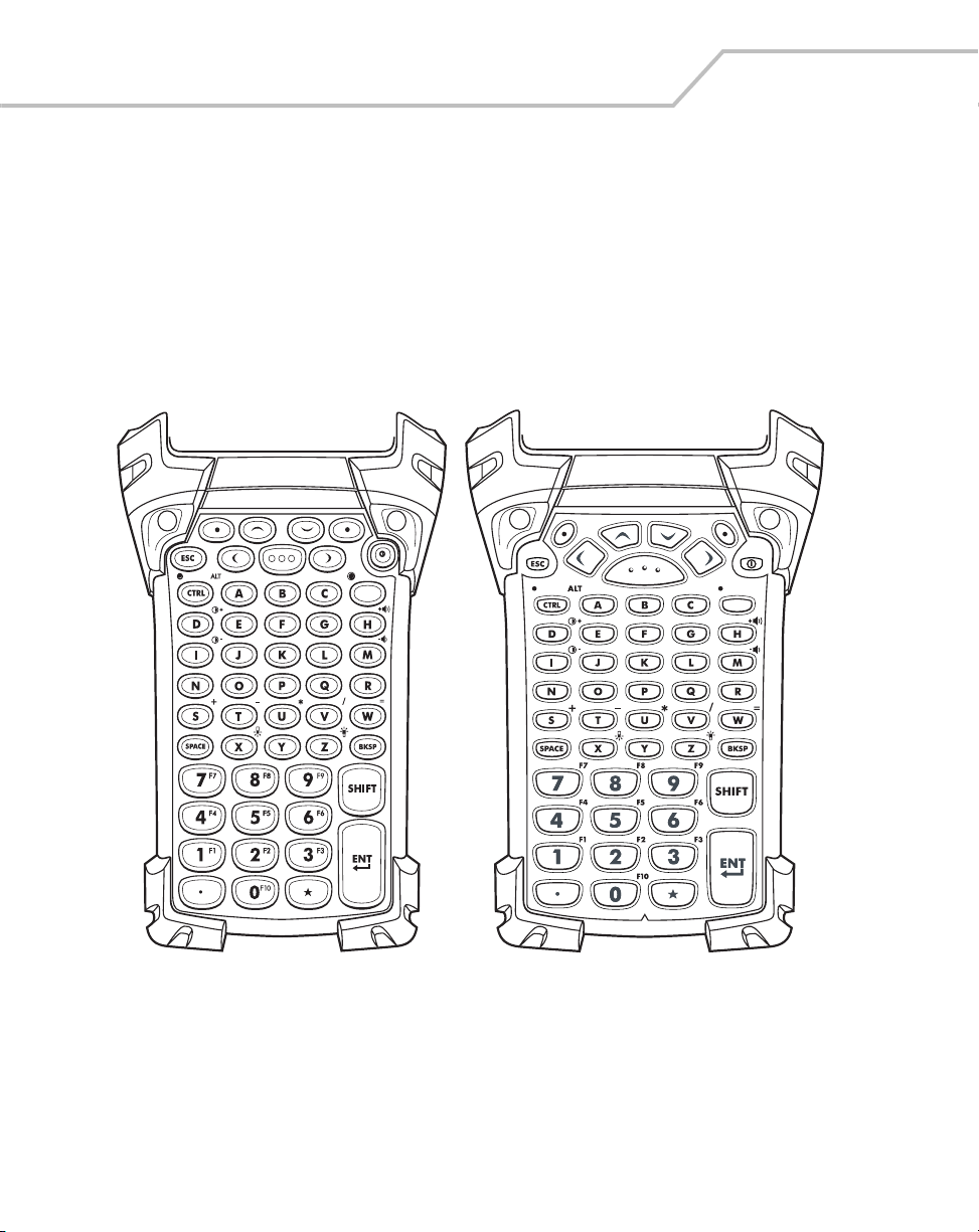
2-10
MC9000-G Product Reference Guide for Embedded Windows® CE .NET
53-Key Keypad
There are two physical configurations of the 53-key keypad, however both of the keypads are
functionally identical. The 53-key keypads contain a Power button, application keys, scroll keys and
function keys. The keypad is color-coded to indicate the alternate function key (blue) values. Note that
keypad functions can be changed by an application so the mobile computer’s keypad may not function
exactly as described. See Table 2-3 on page 2-11 for key and button descriptions and Table 2-7 on
page 2-22 for the keypad’s special functions.
Figure 2-3. 53-Key Keypads
Page 59

Operating the MC9000-G
Table 2-3. 53-Key Descriptions
Key Description
Power (red) Powers the mobile computer on and off.
Used to reset the mobile computer, see Resetting the Mobile Computer
on page 2-41.
Green/Red Dot Unassigned application function key. See Appendix B, Keypad Maps for
mapping details.
Scan (yellow) Scan key - used for scanning applications, this key has the same
function as pulling the trigger.
Scroll Up and Down Moves up and down from one item to another.
Increases/decreases specified values.
Scroll Left and Right Moves left and right from one item to another.
Increases/decreases specified values.
2-11
ESC Exits the current operation.
Alpha Use the alpha keys for alphabetic characters.
. . .
SPACE/BKSP Space and backspace functions.
Numeric/Application Numeric value keys - can have applications assigned with function
key(s).
. . .
Function (blue) Press and release the blue function key to activate the keypad alternate
LED
functions (shown on the keypad in blue). The keypad LED lights and the
icon appears on the taskbar, see
release the blue function key again to return to the normal keypad
functions.
Table 2-9 on page 2-26. Press and
Page 60

2-12
MC9000-G Product Reference Guide for Embedded Windows® CE .NET
Table 2-3. 53-Key Descriptions (Continued)
Key Description
Control Press and release the CTRL key to activate the keypad alternate CTRL
LED
Shift Press and release the SHIFT key to activate the keypad alternate SHIFT
Period/Decimal Point Produces a period for alpha entries and a decimal point for numeric
Star Produces an asterisk.
Enter Executes a selected item or function.
functions. The keypad LED lights and the icon appears on the
taskbar. Press and release the CTRL key again to return to the normal
keypad functions.
functions. The icon appears on the taskbar. Press and release the
SHIFT key again to return to the normal keypad functions.
entries.
For detailed keypad configurations including ASCII values and VK codes, see
Appendix B, Keypad Maps.
Page 61

Operating the MC9000-G
3270 Emulator
There are two physical configurations of the 3270 emulator keypad, however both of the keypads are
functionally identical. The 3270 emulator keypad contains a Power button, application keys, scroll
keys and a function key. The keypad is color-coded to indicate the alternate function key (blue) values.
Note that keypad functions can be changed by an application so the mobile computer’s keypad may
not function exactly as described. See Table 2-4 on page 2-14 for key and button descriptions and
Table 2-7 on page 2-22 for the keypad’s special functions.
2-13
Figure 2-4. 3270 Emulator Keypad
The 3270 emulator keypad is only used when the mobile computer is running
the 3270 emulation software. When the mobile computer is not running the
3270 emulation software, the 3270 keypad functions are the same as a 53key keypad.
Page 62

2-14
MC9000-G Product Reference Guide for Embedded Windows® CE .NET
Table 2-4. 3270 Emulator Descriptions
Key Description
Power (red) Powers the mobile computer on and off.
Used to reset the mobile computer, see Resetting the Mobile Computer
on page 2-41.
Green/Red Dot Unassigned application function key. See Appendix B, Keypad Maps for
mapping details.
Scan (yellow) Scan key - used for scanning applications, this key has the same
function as pulling the trigger.
Scroll Up and Down Moves up and down from one item to another.
Increases/decreases specified values.
Scroll Left and Right Moves left and right from one item to another.
Increases/decreases specified values.
CLR Exits the current operation.
Alpha Use the alpha keys for alphabetic characters.
. . .
SPACE/BKSP Space and backspace functions.
Application These keys can be assigned to an application.
. . .
Function (blue) Press and release the blue function key to activate the keypad alternate
functions (shown on the keypad in blue). The keypad LED lights and the
LED
icon appears on the taskbar, see
release the blue function key again to return to the normal keypad
functions.
Table 2-9 on page 2-26. Press and
Page 63

Operating the MC9000-G
Table 2-4. 3270 Emulator Descriptions (Continued)
Key Description
Control Press and release the CTRL key to activate the keypad alternate CTRL
functions. The keypad LED lights and the icon appears on the
LED
Shift Press and release the SHIFT key to activate the keypad alternate SHIFT
Period/Decimal Point Produces a period for alpha entries and a decimal point for numeric
Star Produces an asterisk.
Enter Executes a selected item or function.
taskbar. Press and release the CTRL key again to return to the normal
keypad functions.
functions. The icon appears on the taskbar. Press and release the
SHIFT key again to return to the normal keypad functions.
entries.
2-15
For detailed keypad configurations including ASCII values and VK codes, see
Appendix B, Keypad Maps.
Page 64

2-16
MC9000-G Product Reference Guide for Embedded Windows® CE .NET
5250 Emulator
There are two physical configurations of the 5250 emulator keypad, however both of the keypads are
functionally identical. The 5250 emulator keypad contains a Power button, application keys, scroll
keys and a function key. The keypad is color-coded to indicate the alternate function key (blue) values.
Note that keypad functions can be changed by an application so the mobile computer’s keypad may
not function exactly as described. See Table 2-5 on page 2-17 for key and button descriptions and
Table 2-7 on page 2-22 for the keypad’s special functions.
Figure 2-5. 5250 Emulator Keypad
The 5250 emulator keypad is only used when the mobile computer is running
the 5250 emulation software. When the mobile computer is not running the
5250 emulation software, the 5250 keypad functions are the same as a 53key keypad.
Page 65

Table 2-5. 5250 Emulator Descriptions
Key Description
Power (red) Powers the mobile computer on and off.
Used to reset the mobile computer, see Resetting the Mobile Computer on
page 2-41.
Operating the MC9000-G
2-17
Green/Red Dot Unassigned application function key. See
for mapping details.
Scan (yellow) Scan key - used for scanning applications, this key has the same function
as pulling the trigger.
Scroll Up and Down Moves up and down from one item to another.
Scroll Left and Right Moves left and right from one item to another.
ENT Exits the current operation.
Alpha Use the alpha keys for alphabetic characters.
. . .
SPACE/BKSP Space and backspace functions.
Application These keys can be assigned to an application.
Appendix B, Keypad Maps
. . .
Function (blue) Press and release the blue function key to activate the keypad alternate
functions (shown on the keypad in blue). The keypad LED lights and the
LED
icon appears on the taskbar, see
release the blue function key again to return to the normal keypad
functions.
Table 2-9 on page 2-26. Press and
Page 66

2-18
MC9000-G Product Reference Guide for Embedded Windows® CE .NET
Table 2-5. 5250 Emulator Descriptions (Continued)
Key Description
Control Press and release the CTRL key to activate the keypad alternate CTRL
functions. The keypad LED lights and the icon appears on the taskbar.
LED
Shift Press and release the SHIFT key to activate the keypad alternate SHIFT
Period/Decimal Point Produces a period for alpha entries and a decimal point for numeric entries.
Star Produces an asterisk.
Enter Executes a selected item or function.
Press and release the CTRL key again to return to the normal keypad
functions.
functions. The icon appears on the taskbar. Press and release the
SHIFT key again to return to the normal keypad functions.
For detailed keypad configurations including ASCII values and VK codes, see
Appendix B, Keypad Maps.
Page 67

Operating the MC9000-G
VT Emulator
There are two physical configurations of the VT emulator keypad, however both of the keypads are
functionally identical. The VT emulator keypad contains a Power button, application keys, scroll keys
and a function key. The keypad is color-coded to indicate the alternate function key (blue) values. Note
that keypad functions can be changed by an application so the mobile computer’s keypad may not
function exactly as described. See Table 2-6 on page 2-20 for key and button descriptions and Table
2-7 on page 2-22 for the keypad’s special functions.
2-19
Figure 2-6. VT Emulator Keypad
The VT emulator keypad is only used when the mobile computer is running
the VT emulation software. When the mobile computer is not running the VT
emulation software, the VT keypad functions are the same as a 53-key
keypad.
Page 68

2-20
MC9000-G Product Reference Guide for Embedded Windows® CE .NET
Table 2-6. VT Emulator Descriptions
Key Description
Power (red) Powers the mobile computer on and off.
Used to reset the mobile computer, see Resetting the Mobile Computer
on page 2-41.
Green/Red Dot Unassigned application function key. See Appendix B, Keypad Maps for
mapping details.
Scan (yellow) Scan key - used for scanning applications, this key has the same
function as pulling the trigger.
Scroll Up and Down Moves up and down from one item to another.
Scroll Left and Right Moves left and right from one item to another.
ESC Exits the current operation.
Alpha Use the alpha keys for alphabetic characters.
. . .
SPACE/BKSP Space and backspace functions.
Application These keys can be assigned to an application.
. . .
Function (blue) Press and release the blue function key to activate the keypad alternate
functions (shown on the keypad in blue). The keypad LED lights and the
LED
icon appears on the taskbar,
release the blue function key again to return to the normal keypad
functions.
see Table 2-9 on page 2-26. Press and
Page 69

Operating the MC9000-G
Table 2-6. VT Emulator Descriptions (Continued)
Key Description
Control Press and release the CTRL key to activate the keypad alternate CTRL
functions. The keypad LED lights and the icon appears on the
LED
Shift Press and release the SHIFT key to activate the keypad alternate SHIFT
Period/Decimal Point Produces a period for alpha entries and decimal point for numeric
Star Produces an asterisk.
Enter Executes a selected item or function.
taskbar. Press and release the CTRL key again to return to the normal
keypad functions.
functions. The icon appears on the taskbar. Press and release the
SHIFT key again to return to the normal keypad functions.
entries.
2-21
For detailed keypad configurations including ASCII values and VK codes, see
Appendix B, Keypad Maps.
Page 70

2-22
MC9000-G Product Reference Guide for Embedded Windows® CE .NET
Keypad Special Functions
The keypad special functions are color coded on the keypads. For example, on the 53-key keypad, the
display backlight icon is blue indicating that the blue function key must be selected first to access the
display backlight. On the 43-key keypad, the display backlight icon is white indicating that the display
backlight is the default value for that key.
Table 2-7. Keypad Special Functions
53-Key, 3270,
5250, VT
Icon
Keystrokes 43-Key Keystrokes Special Function
Blue function key
and Z
Blue function key
and X
Blue function key
and D
Blue function key
and I
Blue function key
and H
Blue function key
and M
* Blue function key
and CTRL
Blue function key
and F1
Blue function key
and F5
Blue function key
and F4
Blue function key
and F8
Not Available Enables Alt keypad functions.
key Turns on and off the display backlight.
key Turns on and off the keypad backlight.
Increases display contrast (on monochromatic
units only).
Decreases display contrast (on monochromatic
units only).
Increases scan decode beeper volume.
Decreases scan decode beeper volume.
Use of display and keypad backlighting can significantly reduce battery life.
Mobile computers with color screens do not have contrast settings.
Page 71

Operating the MC9000-G
Power Button
Press the red Power button to turn the mobile computer screen on and off. The mobile computer is on
when the display is on and the mobile computer is in suspend mode when the display is off. For more
information, see Starting the Mobile Computer on page 1-15.
Do not hold down any key, button or the trigger, other than the Power button
during a reset.
Cold boot resets the mobile computer, to the default settings. All added applications and
all stored data will be removed. Do not cold boot without support desk approval.
Any data previously synchronized with a computer can be restored during the
next ActiveSync operation. See Chapter 4, Communications for detailed
ActiveSync instructions.
The Power button is also used to reset the mobile computer by performing a warm or cold boot.
• Warm Boot (Soft Reset) - Resets the mobile computer.
• Cold Boot (Hard Reset) - Resets the mobile computer, removes all added applications and
restores all factory default settings.
2-23
For information about rebooting the mobile computer, refer to Resetting the Mobile Computer on page
2-41.
Headphone
An optional headphone is available. The headset plugs into the optional headphone jack located at
the top of the mobile computer, see Figure 1-1 on page 1-3. Set the mobile computer volume
appropriately before putting on the headset. When a headset is plugged into the jack, the speaker is
muted.
Page 72

2-24
MC9000-G Product Reference Guide for Embedded Windows® CE .NET
Series 9000 Demo Window
On initial power up (or on a warm or cold boot) the Series 9000 Demo window appears. The Series
9000 Demo window icon functions are provided in Table 2-8.
Figure 2-7. Series 9000 Demo Window
Table 2-8. Series 9000 Demo Window Functions
Icon Description
Displays the Test Applications window, see Introduction on page 5-3 for a
description of the Test Applications window.
Use to set up and run the demonstration scan application, see ScanSamp2 on page
5-6.
Displays the system file structure, see InkWiz File Browser on page 5-9.
Displays the AudioSamp sample application, see AudioSamp on page 5-
13.
Displays the image viewer sample application, see Images on page 5-14.
Page 73

Table 2-8. Series 9000 Demo Window Functions (Continued)
Icon Description
Displays the control panel menu, see Control Panel on page 3-40.
Starts the PC Link application, see PC Link on page 5-16.
Provides access to the terminal emulators, see Terminal Emulators on page 2-46.
Provides access to the S24 DS Settings, see Mobile Companion on page 6-4.
Provides access to the S24 FH Settings, see Spectrum24 Frequency Hopping (FH)
Settings (1 and 2 MB Radios) on page 6-31.
Provides information about the OTL application, see About OTL on page 5-17.
Operating the MC9000-G
2-25
The Series 9000 Demo window is the factory default launcher menu.
Application specific shells may vary.
Page 74

2-26
MC9000-G Product Reference Guide for Embedded Windows® CE .NET
Taskbar
The taskbar (at the bottom of the window) displays the Start button, active programs (in this case PC
Link and Mobile Companion), battery status and the communication status. The default taskbar icons
are described in Table 2-9 and the default taskbar buttons are described in Table 2-10 on page 2-27.
The Start button functions are described in Start Button on page 2-28.
Start Button
Menu and Application Buttons
Open Programs and Status Icons
Figure 2-8. Taskbar
Table 2-9. Taskbar Icons
Icon Description
Indicates that the battery is charging.
Indicates that the battery charge is fully charged (100% charge).
The battery status icons provide the battery status in 10% increments from 10% to 100%.
Indicates that the battery is fully charged and the mobile computer is running on external power.
Indicates IP status. Only displays when the mobile computer is in emulation mode.
Indicates that the ActiveSync application is running.
Indicates that the Shift character selection is selected.
Indicates that the Function character selection is selected.
Desktop
Keyboard Input Panel
ALT
Indicates that the Control character selection is selected.
Indicates that the ALT character selection is selected.
Indicates that the Num-lock character selection is selected.
The Mobile Companion utility. Tap to display the LAN status selection menu.
Indicated that the mobile computer is in Alpha mode. The mobile computer automatically enters
Alpha mode when the Terminal Emulators are run.
Page 75

Table 2-10. Taskbar Buttons
Icon Description
The Start button. Tap to display the Start menu.
The Keyboard Input Panel, display button. Tap to display the Keyboard Input Panel.
The Keyboard Input Panel hide button. Tap to hide the Keyboard Input Panel.
The Desktop display button. Tap to display the Desktop.
Operating the MC9000-G
2-27
Page 76
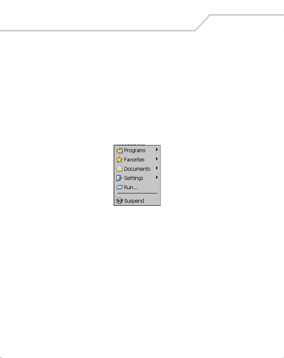
2-28
MC9000-G Product Reference Guide for Embedded Windows® CE .NET
Start Button
Tap the Start button to launch the Start Menu or tap the Start button while in the ALT state and the
Task Manager, Properties menu appears, see Task Manager and Properties on page 2-30.
• Programs: Use to access available programs
• Favorites: Displays files in Favorites
• Documents: Displays files in Documents
• Settings: Accesses the Control Panel, the Network and Dial-up Connections and the Taskbar
and Start Menus
• Run: Runs a program or application
• Suspend: Suspends the mobile computer.
Figure 2-9. Start Menu
Keyboard Input Panel Button
Use the Keyboard Input Panel as an alternate input device, see Entering Information Using the
Keyboard Input Panel on page 2-33.
Desktop Button
Use the Desktop button to minimize all open programs and display the Desktop.
Major desktop functions include:
• My Computer: Double-tap icon to open My Computer.
• Recycle Bin: Deleted files remain in the recycle bin until the recycle bin is emptied. Once
emptied the files cannot be retrieved.
• Remote Desktop Connection: Use the Remote Desktop Connection icon to access the
Remote Desktop Connection window.
Page 77

Operating the MC9000-G
Taskbar Icons
The taskbar icons display the function status, indicate what programs are active and indicate the
battery charge status. The taskbar icons are provided in Table 2-9 on page 2-26.
Status Icons
The status icons indicate the function key status. If the Function, Shift, CTRL or ALT functions are
active the appropriate status icon is displayed.
Active Programs Icons
If more than one program is active, the applications’ icons can be used to toggle between the open
programs (applications). Tap on a taskbar application to maximize the application.
AC Power/Battery Status Icons
The AC Power/Battery Status icons are shown in the taskbar to indicate the present power supply
status of the mobile computer. The battery status icons provide the battery status in 10% increments
from 10% to 100%, see Table 2-9 on page 2-26. Battery status can also be viewed on the battery
status window, see Battery on page 3-45.
The amber LED in the mobile computer indicator LED bar, see Figure 1-1 on
page 1-3, also indicates low battery status and/or incorrect battery insertion.
2-29
Page 78

2-30
MC9000-G Product Reference Guide for Embedded Windows® CE .NET
Task Manager and Properties
Use the Task Manager to control an application’s use and use the Properties functions to set display
and clock options.
Task Manager
1. Select Function - CTRL, (to activate the ALT state) and tap the Start button to display the
Task Manager, Properties Selection menu.
2. Tap Task Manager to display the Task Manager window.
Figure 2-10. Task Manager, Properties Selection Menu
3. Tap a task in the Active Tasks list and tap Switch To to make that task the primary task, or
tap End Task to end the selected task.
4. Tap X to exit the Task Manager window.
Figure 2-11. Task Manager Window
Page 79

Operating the MC9000-G
Properties
1. Select Function - CTRL, (to activate the ALT state) and tap the Start button to display the
Task Manager, Properties window, see Figure 2-10 on page 2-30.
2. Tap Properties to display the Taskbar and Start Menu, General Tab.
3. This menu provides taskbar options:
• Check the Always on Top checkbox to keep the taskbar on top of all other windows.
• Check the AutoHide checkbox to make the taskbar disappear, touch the bottom of the
display to make the taskbar return.
• Check the Show Clock checkbox to display the clock on the taskbar.
4. Tap OK to save the settings and exit the window.
2-31
Figure 2-12. Taskbar and Start Menu, General Tab
Page 80

2-32
MC9000-G Product Reference Guide for Embedded Windows® CE .NET
Advanced Tab
1. Tap the Advanced tab to enter the Taskbar and Start Menu, Advanced Tab.
2. Tap the Clear button to delete all of the documents listed in the Start - Documents entry,
see Start Button on page 2-28. Typically this list is empty, but if there were documents in the
list the Clear button would delete them.
3. Tap the Expand Control Panel checkbox to display the entire contents of the MS control
panel in list form, rather than icons.
Figure 2-13. Taskbar and Start Menu, Advanced Tab
4. Tap OK to save the settings and exit the window.
Page 81

Operating the MC9000-G
Entering Information
To enter information:
• Use the keypad.
• Use the input panel (soft keyboard) to enter typed text.
• Scan bar code data into data fields.
• Use Microsoft
the mobile computer. For more information on ActiveSync, see Chapter 4, Communications
or ActiveSync Help on the host computer.
Entering Information Using Keypad
The alphanumeric keypads produce the 26-character alphabet (A-Z), numbers (0-9), function keys and
assorted characters. The keypads’ default characters/functions are printed white and the function
character/functions are printed blue. See Keypads on page 2-3 for keypad configurations and see
Table 2-7 on page 2-22 for keypad special functions.
Entering Information Using the Keyboard Input Panel
Use the keyboard input panel to enter information in any program. To launch the keyboard input panel,
tap Start, tap the Soft KeyBd menu selection and then tap the icon. Tap on a key to enter the key’s
value. Tap on the keyboard selection icon to display or to hide the keyboard input panel.
®
ActiveSync® to synchronize or copy information from the host computer to
2-33
Figure 2-14. Keyboard Input Panel
Entering Data via the Bar Code Scanner (Scan Wedge)
The integrated bar code scanner uses the Scan Wedge program to scan data into data fields in the
same way data is entered via the keypad. The Scan Wedge program is provided as a sample
application in the SMDK, see Chapter 8, Software Installation for the SMDK installation.
Page 82

2-34
MC9000-G Product Reference Guide for Embedded Windows® CE .NET
Data Capture
Mobile computers with an integrated laser scanner allow you to collect data by scanning one
dimensional bar codes.
Mobile computers with an integrated imager allow you to collect data by decoding one dimensional
bar codes (including RSS) and two dimensional bar codes (including PDF417 and DataMatrix), and
capture and download images to a host for a variety of imaging applications.
Mobile computers with RFID technology (MC9000-G) allow data collection by decoding in-range RFID
tags that beam back to the mobile computer the information they contain.
Laser Scanning
To scan bar codes with the mobile computer:
1. Ensure that the mobile computer is loaded with a scanning application. See ScanSamp2
Windows on page 5-6 for a sample scanning application.
2. Aim the scan exit window at the bar code.
3. Pull the trigger. Ensure the red scan beam covers the entire bar code. The indicator LED bar
illuminates red to indicate that the laser is on. The indicator LED bar illuminates green and
a beep sounds to indicate a successful decode.
Right
Wrong
Figure 2-15. Laser Aiming
Optimal scanning distance varies with bar code density and scanner optics.
• Hold the scanner farther away for larger symbols.
• Move the scanner closer for symbols with bars that are close together.
Scanning procedures depend on the application and mobile computer
configuration. An application may use different scanning procedures from the
one listed above.
Page 83

Operating the MC9000-G
Indicator LED Bar
The Indicator LED bar provides a visual indication of the scan status, see Figure 1-1 on page 1-3.
Table 2-11. Scan LED Indicators
LED Status Indication
Off Not scanning.
Solid Red Laser enabled, scanning in process.
Solid Green Successful decode.
Scanning Considerations
Typically, scanning is a simple matter of aim, scan/decode and a few quick trial efforts master it.
However, two important considerations can be used to optimize any scanning performance:
• Range
Any scanning device decodes well over a particular working range — minimum and
maximum distances from the bar code. This range varies according to bar code density and
scanning device optics.
2-35
Scanning within range brings quick and constant decodes; scanning too close or too far
away prevents decodes. Move the scanner closer and further away to find the right working
range for the bar codes being scanned. However, the situation is complicated by the
availability of various integrated scanning modules. The best way to specify the appropriate
working range per bar code density is through a chart called a decode zone for each scan
module. A decode zone simply plots working range as a function of minimum element widths
of bar code symbols.
• Angle
Scanning angle is important for promoting quick decodes. When laser beams reflect directly
back into the scanner from the bar code, this specular reflection can “blind” the scanner.
To avoid this, scan the bar code so that the beam does not bounce directly back. But don’t
scan at too sharp an angle; the scanner needs to collect scattered reflections from the scan
to make a successful decode. Practice quickly shows what tolerances to work within.
Contact the Symbol Support Center if chronic scanning difficulties develop.
Decoding of properly printed bar codes should be quick and effortless.
Page 84

2-36
MC9000-G Product Reference Guide for Embedded Windows® CE .NET
Imaging
The imager version of the mobile computer has the following features:
• Omnidirectional reading of a variety of bar code symbologies, including the most popular
linear, postal, PDF417 and 2-D matrix code types.
• The ability to capture and download images to a host for a variety of imaging applications.
• Advanced intuitive laser aiming for easy point-and-shoot operation.
Imager
The imager uses digital camera technology to take a digital picture of a bar code, stores the resulting
image in its memory and executes state-of-the-art software decoding algorithms to extract the data
from the image. A typical bar code decoding process is as follows:
1. Aim the imager version of the mobile computer at a bar code and pull the trigger.
2. The red laser aiming pattern turns on to assist in aiming the mobile computer.
3. If necessary, the mobile computer turns on its red LEDs to illuminate the target bar code.
4. The mobile computer takes a digital picture (image) of the bar code and stores it in memory
for decoding.
5. An audible beep occurs indicating the bar code was decoded properly.
6. Release the trigger.
This process usually occurs instantaneously. Steps 2 - 4 are repeated on poor or difficult bar codes as
long as the trigger remains pulled.
Operational Modes
The imager version of the mobile computer has two modes of operation: Decode Mode and Image
Capture Mode, activated by pulling the trigger.
Decode Mode
In this default mode, upon pulling the trigger, the Imager attempts to locate and decode enabled bar
codes within its field of view. The Imager remains in this mode as long as the trigger is pulled, or until
a bar code is decoded.
Page 85

Operating the MC9000-G
Image Capture Mode
In this default mode, upon pulling the trigger, the Imager attempts to locate and decode enabled bar
codes within its field of view. The Imager remains in this mode as long as the trigger is pulled, or until
a bar code is decoded.
Aiming the Imager
The imager version of the mobile computer projects a laser aiming pattern (shown below) similar to
those used on cameras. The aiming pattern is used to position the bar code or object within the field
of view.
Figure 2-16. Laser Aiming Pattern
Imager symbol scanning:
2-37
1. Center the symbol in any orientation within the aiming pattern. Ensure the entire symbol is
within the rectangular area formed by the brackets in the aiming pattern.
Linear bar code
Symbol
View Finder
(Aiming Pattern)
PDF417 symbol
Figure 2-17. Centering Symbol in Aiming Pattern
Page 86

2-38
MC9000-G Product Reference Guide for Embedded Windows® CE .NET
The imager can also read a bar code presented within the aiming pattern but not centered,
such as the figure below on the left. The figure on the right, however, can not be decoded.
Right
Wrong
Figure 2-18. Imager Aiming
2. The aiming pattern is smaller when the Imager is closer to the symbol and larger when it is
farther from the symbol. Scan symbols with smaller bars or elements (mil size) closer to the
unit and those with larger bars or elements (mil size) farther from the unit.
3. Hold the mobile computer between two and nine inches (depending on symbol density) from
the symbol, centering the aiming pattern cross hairs on the symbol.
4. Press and hold the trigger until the mobile computer beeps, indicating the bar code is
successfully decoded.
Scanning Tips
Optimal scanning distance varies with bar code density and scanner optics.
• Hold the scanner farther away for larger symbols.
• Move the scanner closer for symbols with bars that are close together.
Scanning procedures depend on the application and mobile computer
configuration. An application may use different scanning procedures from the
one listed above.
Page 87

Operating the MC9000-G
RFID (MC9000-G RFID Only)
While the trigger is pressed on MC9000-G RFID mobile computers with RFID technology, the mobile
computer interrogates all of the RFID Class 0 and Class 1 tags within the radio frequency (RF) field of
view. The mobile computer captures data from each new tag found. When the trigger is released, the
mobile computer stops interrogating tags. In addition, RFID tag data can be stored on the mobile
computer. Using the MC9000-G RFID sample application, tags that are read display in the main RFID
Tags window, see Figure 5-24 on page 5-28.
For more information about reading RFID tags and using MC9000-G RFID mobile computers, see RFID
on page 5-28.
Reading RFID Tags
1. Ensure that an RFID tag reader enabled application is loaded on the mobile computer.
2. Aim the scan exit window at the tag.
2-39
Figure 2-19. RFID Class 0 / Class 1 Tag Reading
For a successful tag read, the allowable read distance from the front of the
mobile computer’s scan exit window to the tag is 0.2 ft. - 10 ft. (0.061 m to 3.1
m). Reader motion horizontally and/or vertically may enhance tag reading
ability.
Page 88

2-40
MC9000-G Product Reference Guide for Embedded Windows® CE .NET
3. Position the mobile computer horizontally or vertically (as shown in Figure 2-19), depending
on the orientation of the tag.
4. Pull the trigger.
5. An audible beep sounds, by default, and the Indicator LED bar flashes green one time to
indicate the tag was decoded successfully.
6. Release the trigger.
Tag decoding usually occurs instantaneously. The mobile computer repeats
the steps required to read a tag as long as the trigger remains pulled.
Scan LED Indicator
The Indicator LED bar on the mobile computer provides a visual indication of the scan status. See
Figure 1-1 on page 1-3 for the location of the Indicator LED bar.
Table 2-12. Scan LED Indicators
LED Status Indication
MC9000-G Series:
Off Not scanning.
Solid Red Laser enabled, scanning/imaging in process.
Solid Green Successful decode.
MC9000-G RFID:
Off Not scanning.
Flash Once Green Successful decode.
Page 89

Operating the MC9000-G
Resetting the Mobile Computer
If the mobile computer stops responding to input, reset it. There are two reset functions, warm boot
and cold boot. A warm boot restarts the mobile computer by closing all running programs. All data
that is not saved is lost.
A cold boot also restarts the mobile computer, but erases all stored records and entries from RAM. In
addition it returns formats, preferences and other settings to the factory default settings.
Perform a warm boot first. This restarts the mobile computer and saves all stored records and entries.
If the mobile computer still does not respond, perform a cold boot.
Performing a Warm Boot
Hold down the Power button for approximately five seconds. As soon as the mobile computer starts
to perform a warm boot release the Power button.
Or the warm boot command can be executed from the Programs menu, tap Start - Programs - Warm
Boot.
Files that remain open during a warm boot may not be retained.
2-41
Page 90

2-42
MC9000-G Product Reference Guide for Embedded Windows® CE .NET
Performing a Cold Boot
A cold boot restarts the mobile computer and erases all user stored records and entries from RAM.
Never perform a cold boot unless a warm boot does not solve the problem.
Do not hold down any key, button or the trigger, other than the Power button
during a reset.
Cold boot resets the mobile computer, to the default settings. All added applications and
all stored data will be removed. Do not cold boot without support desk approval.
Any data previously synchronized with a computer can be restored during the
next ActiveSync operation. See Chapter 4, Communications for detailed
ActiveSync instructions.
To perform a cold boot:
1. Eject Battery to the first stop position.
2. Press and hold the Power button, while pushing the battery back into the fully inserted
position.
3. Continue to hold the Power button for 15 seconds. After the first five seconds the unit may
start to perform a warm boot. The message Warm Boot appears in the upper left hand corner
of the screen. Continue holding the Power button and the unit cycles into a cold boot. The
message Booting System appears in the top center of the screen.
4. As the mobile computer initializes its Flash File system, the Symbol splash window, Figure
1-7 on page 1-15 appears for about a minute.
5. Calibrate the screen. See Calibration Screen on page 1-16 to calibrate the mobile computer
display.
Page 91

Operating the MC9000-G
Waking the Mobile Computer
The wakeup conditions are configurable and the current factory default settings are subject to
change/update.
The mobile computer wakeup configuration is set in the registry file, registry file editing procedures
are provided in the SMDK, refer to Chapter 8, Software Installation for the SMDK installation. Table
2-13 lists the wakeup conditions settings.
Table 2-13. Wakeup Conditions
Status Description Action Conditions for wakeup
Power Off When the mobile computer goes into
sleep mode by pressing P
these actions wake the mobile
computer.
Auto Off When the mobile computer goes into
sleep mode by an automatic poweroff function, these actions wake the
mobile computer.
ower,
Power 1. Power button is pressed.
2. AC power added or removed.
Trigger Trigger is pressed.
WLAN Wireless LAN accesses the mobile computer.
Clock Real Time Clock set to wake up.
Power 1. Power button is pressed.
2. AC power added or removed.
Trigger Trigger is pressed.
WLAN Wireless LAN accesses the mobile computer.
Clock Real Time Clock set to sleep.
2-43
Page 92

2-44
MC9000-G Product Reference Guide for Embedded Windows® CE .NET
File System Directory Structure
The mobile computer directory structure displays all of the file folders, see Figure 2-20. The preinstalled folders are in flash file system memory and optional removable storage devices (MMC
storage cards).
Figure 2-20. Mobile Computer Directory Structure
• Application and Platform folders are located in flash file system memory.
• The Windows, Program Files, profiles, and My Documents folders are composites, RAM
based folders generated from ROM (many of these files are marked read only).
• The Network folder is a link to file systems mapped using the network redirector. The files
do not physically reside on the terminal.
• The Temp and Recycled folders typically contain RAM based files.
All files copied to the RAM based folders are lost after a cold boot.
Page 93

Operating the MC9000-G
Flash Storage
In addition to the RAM-based storage the mobile computer is also equipped with a non-volatile Flashbased storage area which can store data (partitions) that can not be corrupted by a cold boot, see
Flash Storage on page 11-27 for a detailed discussion.
Startup Folder
The Applications/Startup folder is used to launch programs automatically when the mobile computer
is started, either after a warm or cold boot.
The Windows/Startup folder is not supported.
There are two ways to launch programs automatically:
1. Place the executable in the Startup folder of the Application partition.
2. Place a .run file in the Startup folder of the Application partition.
Refer to the SMDK Help File for Symbol Terminals included with the SMDK for more information on
the Startup folder.
2-45
Run Files
A .run file is a simple text file that contains the path to an application as well as the name of the
application to run.
Refer to the SMDK Help File for Symbol Terminals included with the SMDK for more information on
the Startup folder.
Audio Event Aliasing
Audio Event Aliasing is the means by which standard Windows .wav files are rendered on a nonaudio terminal using only a beeper.
The audio driver of the mobile computer supports a feature called Event Aliasing. This feature allows
a special .wav file to play. This .wav file replaces the sound normally produced when running a .wav
file with other actions (such as LED flashing, etc.).
This feature allows applications that play .wav files to be portable between two devices, one that
supports real audio and one that supports audio aliasing.
Page 94

2-46
MC9000-G Product Reference Guide for Embedded Windows® CE .NET
Terminal Emulators
Use the Terminal Emulator icon to enter the Wavelink terminal emulator application.
From the Series 9000 Demo window, double-tap the Terminal Emulators icon. The Terminal Emulator
window appears.
To exit, tap TelnetCE Options and tap Exit.
Figure 2-21. Terminal Emulator Windows
Refer to the documentation provided with the terminal emulator software package for setup and use.
Page 95

Settings
Chapter Contents
Introduction. . . . . . . . . . . . . . . . . . . . . . . . . . . . . . . . . . . . . . . . . . . . . . . . . . . . . . . . . . . . . . . . . . . . . . . . .3-5
Windows Control Panel Menu . . . . . . . . . . . . . . . . . . . . . . . . . . . . . . . . . . . . . . . . . . . . . . . . . . . . . . . . . .3-5
Bluetooth Device Properties. . . . . . . . . . . . . . . . . . . . . . . . . . . . . . . . . . . . . . . . . . . . . . . . . . . . . . . . 3-8
Bluetooth/S24 Power Settings. . . . . . . . . . . . . . . . . . . . . . . . . . . . . . . . . . . . . . . . . . . . . . . . . .3-8
Starting Bluetooth . . . . . . . . . . . . . . . . . . . . . . . . . . . . . . . . . . . . . . . . . . . . . . . . . . . . . . . . . .3-11
Certificates . . . . . . . . . . . . . . . . . . . . . . . . . . . . . . . . . . . . . . . . . . . . . . . . . . . . . . . . . . . . . . . . . . . .3-15
Date/Time. . . . . . . . . . . . . . . . . . . . . . . . . . . . . . . . . . . . . . . . . . . . . . . . . . . . . . . . . . . . . . . . . . . . .3-16
Device Management . . . . . . . . . . . . . . . . . . . . . . . . . . . . . . . . . . . . . . . . . . . . . . . . . . . . . . . . . . . .3-17
Dialing. . . . . . . . . . . . . . . . . . . . . . . . . . . . . . . . . . . . . . . . . . . . . . . . . . . . . . . . . . . . . . . . . . . . . . . .3-18
Display . . . . . . . . . . . . . . . . . . . . . . . . . . . . . . . . . . . . . . . . . . . . . . . . . . . . . . . . . . . . . . . . . . . . . . .3-20
Background Tab . . . . . . . . . . . . . . . . . . . . . . . . . . . . . . . . . . . . . . . . . . . . . . . . . . . . . . . . . . . .3-20
Appearance Tab . . . . . . . . . . . . . . . . . . . . . . . . . . . . . . . . . . . . . . . . . . . . . . . . . . . . . . . . . . . .3-21
Input Panel . . . . . . . . . . . . . . . . . . . . . . . . . . . . . . . . . . . . . . . . . . . . . . . . . . . . . . . . . . . . . . . . . . . . 3-22
Keyboard. . . . . . . . . . . . . . . . . . . . . . . . . . . . . . . . . . . . . . . . . . . . . . . . . . . . . . . . . . . . . . . . . . . . . .3-23
Page 96

3-2
MC9000-G Product Reference Guide for Embedded Windows® CE .NET
Mouse. . . . . . . . . . . . . . . . . . . . . . . . . . . . . . . . . . . . . . . . . . . . . . . . . . . . . . . . . . . . . . . . . . . . . . . .3-24
Network and Dial-up Connections . . . . . . . . . . . . . . . . . . . . . . . . . . . . . . . . . . . . . . . . . . . . . . . . . .3-25
Owner . . . . . . . . . . . . . . . . . . . . . . . . . . . . . . . . . . . . . . . . . . . . . . . . . . . . . . . . . . . . . . . . . . . . . . . .3-26
Identification Tab . . . . . . . . . . . . . . . . . . . . . . . . . . . . . . . . . . . . . . . . . . . . . . . . . . . . . . . . . . .3-26
Notes Tab . . . . . . . . . . . . . . . . . . . . . . . . . . . . . . . . . . . . . . . . . . . . . . . . . . . . . . . . . . . . . . . . .3-27
Network ID Tab. . . . . . . . . . . . . . . . . . . . . . . . . . . . . . . . . . . . . . . . . . . . . . . . . . . . . . . . . . . . .3-27
PC Connection. . . . . . . . . . . . . . . . . . . . . . . . . . . . . . . . . . . . . . . . . . . . . . . . . . . . . . . . . . . . . . . . . .3-28
Regional Settings . . . . . . . . . . . . . . . . . . . . . . . . . . . . . . . . . . . . . . . . . . . . . . . . . . . . . . . . . . . . . . .3-29
Region Tab . . . . . . . . . . . . . . . . . . . . . . . . . . . . . . . . . . . . . . . . . . . . . . . . . . . . . . . . . . . . . . . .3-29
Number Tab . . . . . . . . . . . . . . . . . . . . . . . . . . . . . . . . . . . . . . . . . . . . . . . . . . . . . . . . . . . . . . .3-30
Currency Tab. . . . . . . . . . . . . . . . . . . . . . . . . . . . . . . . . . . . . . . . . . . . . . . . . . . . . . . . . . . . . . .3-30
Time Tab. . . . . . . . . . . . . . . . . . . . . . . . . . . . . . . . . . . . . . . . . . . . . . . . . . . . . . . . . . . . . . . . . .3-31
Date Tab . . . . . . . . . . . . . . . . . . . . . . . . . . . . . . . . . . . . . . . . . . . . . . . . . . . . . . . . . . . . . . . . . .3-31
Remove Programs. . . . . . . . . . . . . . . . . . . . . . . . . . . . . . . . . . . . . . . . . . . . . . . . . . . . . . . . . . . . . . .3-32
Stylus . . . . . . . . . . . . . . . . . . . . . . . . . . . . . . . . . . . . . . . . . . . . . . . . . . . . . . . . . . . . . . . . . . . . . . . .3-33
Double-Tap Tab . . . . . . . . . . . . . . . . . . . . . . . . . . . . . . . . . . . . . . . . . . . . . . . . . . . . . . . . . . . .3-33
Calibrate Tab . . . . . . . . . . . . . . . . . . . . . . . . . . . . . . . . . . . . . . . . . . . . . . . . . . . . . . . . . . . . . .3-34
System . . . . . . . . . . . . . . . . . . . . . . . . . . . . . . . . . . . . . . . . . . . . . . . . . . . . . . . . . . . . . . . . . . . . . . .3-35
General Tab . . . . . . . . . . . . . . . . . . . . . . . . . . . . . . . . . . . . . . . . . . . . . . . . . . . . . . . . . . . . . . .3-35
Memory Tab . . . . . . . . . . . . . . . . . . . . . . . . . . . . . . . . . . . . . . . . . . . . . . . . . . . . . . . . . . . . . . .3-36
Device Name Tab . . . . . . . . . . . . . . . . . . . . . . . . . . . . . . . . . . . . . . . . . . . . . . . . . . . . . . . . . . .3-37
Copyrights Tab . . . . . . . . . . . . . . . . . . . . . . . . . . . . . . . . . . . . . . . . . . . . . . . . . . . . . . . . . . . . .3-38
Series 9000 Demo Window . . . . . . . . . . . . . . . . . . . . . . . . . . . . . . . . . . . . . . . . . . . . . . . . . . . . . . . . . . .3-39
Control Panel. . . . . . . . . . . . . . . . . . . . . . . . . . . . . . . . . . . . . . . . . . . . . . . . . . . . . . . . . . . . . . . . . . . . . . .3-40
About Ctl Panel. . . . . . . . . . . . . . . . . . . . . . . . . . . . . . . . . . . . . . . . . . . . . . . . . . . . . . . . . . . . . . . . .3-41
System Version. . . . . . . . . . . . . . . . . . . . . . . . . . . . . . . . . . . . . . . . . . . . . . . . . . . . . . . . . . . . . . . . .3-42
Unique Unit ID . . . . . . . . . . . . . . . . . . . . . . . . . . . . . . . . . . . . . . . . . . . . . . . . . . . . . . . . . . . . . . . . .3-43
Persist. . . . . . . . . . . . . . . . . . . . . . . . . . . . . . . . . . . . . . . . . . . . . . . . . . . . . . . . . . . . . . . . . . . . . . . .3-44
Battery . . . . . . . . . . . . . . . . . . . . . . . . . . . . . . . . . . . . . . . . . . . . . . . . . . . . . . . . . . . . . . . . . . . . . . .3-45
Power Settings . . . . . . . . . . . . . . . . . . . . . . . . . . . . . . . . . . . . . . . . . . . . . . . . . . . . . . . . . . . . . . . . .3-46
Bluetooth Settings . . . . . . . . . . . . . . . . . . . . . . . . . . . . . . . . . . . . . . . . . . . . . . . . . . . . . . . . . . . . . .3-50
Date and Time . . . . . . . . . . . . . . . . . . . . . . . . . . . . . . . . . . . . . . . . . . . . . . . . . . . . . . . . . . . . . . . . .3-51
Printer Settings. . . . . . . . . . . . . . . . . . . . . . . . . . . . . . . . . . . . . . . . . . . . . . . . . . . . . . . . . . . . . . . . .3-52
Comm Settings . . . . . . . . . . . . . . . . . . . . . . . . . . . . . . . . . . . . . . . . . . . . . . . . . . . . . . . . . . . . . . . . .3-55
Display Settings . . . . . . . . . . . . . . . . . . . . . . . . . . . . . . . . . . . . . . . . . . . . . . . . . . . . . . . . . . . . . . . .3-56
Page 97

Settings
Audio Settings . . . . . . . . . . . . . . . . . . . . . . . . . . . . . . . . . . . . . . . . . . . . . . . . . . . . . . . . . . . . . . . . .3-57
Scanner Settings . . . . . . . . . . . . . . . . . . . . . . . . . . . . . . . . . . . . . . . . . . . . . . . . . . . . . . . . . . . . . . .3-58
Reader Parameters. . . . . . . . . . . . . . . . . . . . . . . . . . . . . . . . . . . . . . . . . . . . . . . . . . . . . . . . . .3-59
Interface Parameters . . . . . . . . . . . . . . . . . . . . . . . . . . . . . . . . . . . . . . . . . . . . . . . . . . . . . . . .3-62
Scan Parameters . . . . . . . . . . . . . . . . . . . . . . . . . . . . . . . . . . . . . . . . . . . . . . . . . . . . . . . . . . .3-63
WAV File. . . . . . . . . . . . . . . . . . . . . . . . . . . . . . . . . . . . . . . . . . . . . . . . . . . . . . . . . . . . . . . . . .3-65
Device Information . . . . . . . . . . . . . . . . . . . . . . . . . . . . . . . . . . . . . . . . . . . . . . . . . . . . . . . . . .3-66
Scanner Version . . . . . . . . . . . . . . . . . . . . . . . . . . . . . . . . . . . . . . . . . . . . . . . . . . . . . . . . . . . .3-67
3-3
Page 98

3-4
MC9000-G Product Reference Guide for Embedded Windows® CE .NET
Page 99

Settings
Introduction
This chapter provides basic instructions for customizing the mobile computer by adjusting settings.
The system settings are accessed from the Windows CE Control Panel menu (see Table 3-1 on page
3-6), the Series 9000 Demo menu (see Table 3-4 on page 3-39) and the Control Panel menu (see Table
3-5 on page 3-40).
Windows Control Panel Menu
To view available options for the mobile computer settings, tap Start - Settings - Control Panel.
3-5
Figure 3-1. Windows Control Panel Menu
Table 3-1 lists the applications available in the Windows Control Panel Menu.
Page 100
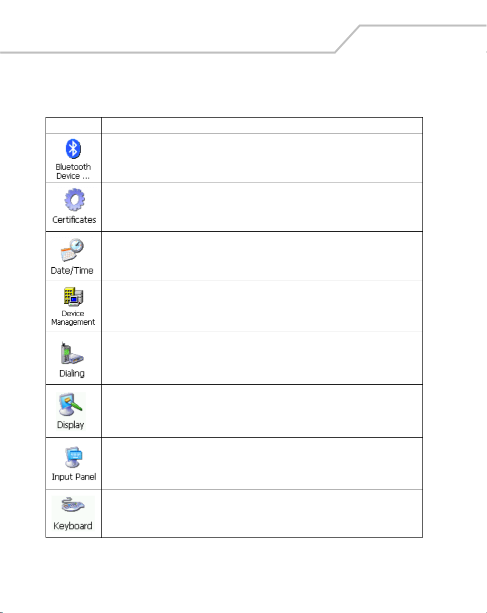
3-6
MC9000-G Product Reference Guide for Embedded Windows® CE .NET
Table 3-1. Windows Control Panel Menu Icons
Icon Description
Scan for, and setup Bluetooth compatible hardware, see Bluetooth Device Properties on page 3-8
for more information.
View and modify digital certificates which are used by some applications for establishing trust for
secure communications, see Certificates on page 3-15 for more information.
Change date, time and time zone information, see Date/Time on page 3-16 for more information.
Configure device management, install and view available software, see Device Management on
page 3-17 for more information.
Set dialing properties for modem communication and change telephony settings, see Dialing on
page 3-18 for more information.
Change desktop background, appearance, backlight, and brightness, see Display on page 3-20 for
more information.
Switch input methods and set input options, see Input Panel on page 3-22 for more information.
Change keyboard repeat delay and rate, see Keyboard on page 3-23 for more information.
 Loading...