

MC55 Enterprise Digital Assistant
Integrator Guide
100
Mbps


MC55 Enterprise Digital Assistant
Integrator Guide
72E-108861-02
Rev. A
March 2009

ii MC55 Integrator Guide
© 2009 by Motorola, Inc. All rights reserved.
No part of this publication may be reproduced or used in any form, or by any electrical or mechanical means,
without permission in writing from Motorola. This includes electronic or mechanical means, such as
photocopying, recording, or information storage and retrieval systems. The material in this manual is subject to
change without notice.
The software is provided strictly on an “as is” basis. All software, including firmware, furnished to the user is on
a licensed basis. Motorola grants to the user a non-transferable and non-exclusive license to use each
software or firmware program delivered hereunder (licensed program). Except as noted below, such license
may not be assigned, sublicensed, or otherwise transferred by the user without prior written consent of
Motorola. No right to copy a licensed program in whole or in part is granted, except as permitted under
copyright law. The user shall not modify, merge, or incorporate any form or portion of a licensed program with
other program material, create a derivative work from a licensed program, or use a licensed program in a
network without written permission from Motorola. The user agrees to maintain Motorola’s copyright notice on
the licensed programs delivered hereunder, and to include the same on any authorized copies it makes, in
whole or in part. The user agrees not to decompile, disassemble, decode, or reverse engineer any licensed
program delivered to the user or any portion thereof.
Motorola reserves the right to make changes to any software or product to improve reliability, function, or
design.
Motorola does not assume any product liability arising out of, or in connection with, the application or use of
any product, circuit, or application described herein.
No license is granted, either expressly or by implication, estoppel, or otherwise under any Motorola, Inc.,
intellectual property rights. An implied license only exists for equipment, circuits, and subsystems contained in
Motorola products.
MOTOROLA and the Stylized M Logo and Symbol and the Symbol logo are registered in the US Patent &
Trademark Office. Bluetooth is a registered trademark of Bluetooth SIG. Microsoft, Windows and ActiveSync
are either registered trademarks or trademarks of Microsoft Corporation. All other product or service names
are the property of their respective owners.
Motorola, Inc.
One Motorola Plaza
Holtsville, New York 11742-1300
http://www.motorola.com/enterprisemobility
Patents
This product is covered by one or more of the patents listed on the website: www.motorola.com/
enterprisemobility/patents.
Revision History
Changes to the original manual are listed below:
Change Date Description
-01 Rev. A 11/20/08 Initial release.
-02 Rev. A 03/06/09 Add MC5574 configuration support.
iii

iv MC55 Integrator Guide

Table of Contents
Patents.................................................................................................................................................. ii
Revision History .................................................................................................................................... iii
About This Guide
Introduction........................................................................................................................................... xi
Documentation Set ............................................................................................................................... xi
Configurations....................................................................................................................................... xii
Software Versions xii
Chapter Descriptions ............................................................................................................................ xiv
Notational Conventions......................................................................................................................... xv
Related Documents .............................................................................................................................. xv
Service Information ............................................................................................................................... xvi
Chapter 1: Getting Started
Introduction .......................................................................................................................................... 1-1
Unpacking the MC55 ........................................................................................................................... 1-1
Getting Started ..................................................................................................................................... 1-1
Installing a microSD Card .............................................................................................................. 1-2
Installing the SIM Card ................................................................................................................... 1-3
Installing the Battery ...................................................................................................................... 1-4
Charging the Battery ...................................................................................................................... 1-5
Charging the Main Battery ....................................................................................................... 1-5
Charging Spare Batteries ......................................................................................................... 1-6
Charging Temperature ............................................................................................................. 1-6
Powering On the MC55 .................................................................................................................. 1-6
Calibrating the Screen ................................................................................................................... 1-6
Resetting the MC55 ............................................................................................................................. 1-6
Performing a Warm Boot ............................................................................................................... 1-6
Performing a Cold Boot .................................................................................................................. 1-7
Performing a Clean Boot ................................................................................................................ 1-7
Waking the MC55 ................................................................................................................................ 1-8

vi MC55 Integrator Guide
Chapter 2: Accessories
Introduction .......................................................................................................................................... 2-1
Single Slot USB Cradle ........................................................................................................................ 2-2
Setup .............................................................................................................................................. 2-2
Charging the MC55 Battery ........................................................................................................... 2-2
Charging the Spare Battery ........................................................................................................... 2-4
Battery Charging Indicators ........................................................................................................... 2-4
Charging Temperature ............................................................................................................. 2-4
Four Slot Ethernet Cradle .................................................................................................................... 2-6
Setup .............................................................................................................................................. 2-6
Daisychaining Ethernet Cradles ..................................................................................................... 2-6
Ethernet Cradle Drivers ................................................................................................................. 2-7
Charging and Communication ....................................................................................................... 2-9
LED Charging Indicators ................................................................................................................ 2-9
Charge LED ............................................................................................................................. 2-9
Speed LED ............................................................................................................................... 2-9
Link LED .................................................................................................................................. 2-9
Charging Temperature ............................................................................................................. 2-9
Four Slot Charge Only Cradle ............................................................................................................. 2-10
Setup .............................................................................................................................................. 2-10
Charging Temperature ............................................................................................................. 2-10
Wall Mount Bracket .............................................................................................................................. 2-11
VCD5500 Vehicle Cradle ..................................................................................................................... 2-13
Requirements ................................................................................................................................. 2-13
Connector Pin-Outs ................................................................................................................. 2-13
Mounting the Cradle ....................................................................................................................... 2-13
Power Connection .......................................................................................................................... 2-14
Charging the MC55 Battery ........................................................................................................... 2-16
Removing the MC55 ................................................................................................................ 2-16
Battery Charging Indicators ........................................................................................................... 2-17
Charging Temperature ............................................................................................................. 2-17
Four Slot Battery Charger .................................................................................................................... 2-18
Spare Battery Charging ................................................................................................................. 2-18
Battery Charging Indicators ........................................................................................................... 2-18
Charging Temperature ............................................................................................................. 2-18
Cables .................................................................................................................................................. 2-20
USB Charging Cable ...................................................................................................................... 2-20
Charge Only Cable ........................................................................................................................ 2-20
Auto Charge Cable ........................................................................................................................ 2-21
Connecting to the MC55 ................................................................................................................ 2-21
Battery Charging Indicators ........................................................................................................... 2-22
Charging Temperature ................................................................................................................... 2-22
Vehicle Holder ..................................................................................................................................... 2-24
Installation Reminders ................................................................................................................... 2-24
Device Mounting Precautions ........................................................................................................ 2-24
Installation ...................................................................................................................................... 2-24
Assembly ................................................................................................................................. 2-25
Windshield Installation ............................................................................................................. 2-25
Flat Surface Installation ........................................................................................................... 2-26

Table of Contents vii
Chapter 3: ActiveSync
Introduction .......................................................................................................................................... 3-1
Installing ActiveSync ............................................................................................................................ 3-1
Mobile Computer Setup ....................................................................................................................... 3-2
Setting Up an ActiveSync Connection on the Host Computer ............................................................. 3-3
Synchronization with a Windows Mobile 6.1 Device ...................................................................... 3-4
Chapter 4: Application Deployment
Introduction .......................................................................................................................................... 4-1
Security ................................................................................................................................................ 4-1
Application Security ....................................................................................................................... 4-1
Digital Signatures ........................................................................................................................... 4-1
Locking Down a Mobile Computer ........................................................................................... 4-2
Installing Certificates ................................................................................................................ 4-3
Device Management Security ........................................................................................................ 4-3
Remote API Security ...................................................................................................................... 4-3
Packaging ............................................................................................................................................ 4-4
Deployment .......................................................................................................................................... 4-4
Installation Using ActiveSync ......................................................................................................... 4-4
Installation Using Storage Card ..................................................................................................... 4-4
Installation Using AirBEAM ............................................................................................................ 4-5
MSP 3.2 ......................................................................................................................................... 4-5
Update Loader Image .................................................................................................................... 4-5
Download Update Loader Package ......................................................................................... 4-5
ActiveSync ............................................................................................................................... 4-5
microSD Card .......................................................................................................................... 4-6
Creating a Splash Screen .............................................................................................................. 4-6
XML Provisioning ................................................................................................................................. 4-7
Creating an XML Provisioning File ................................................................................................. 4-7
XML Provisioning vs. RegMerge and Copy File ............................................................................ 4-7
RegMerge ................................................................................................................................ 4-8
CopyFiles ................................................................................................................................. 4-8
Storage ................................................................................................................................................ 4-9
Random Access Memory ............................................................................................................... 4-9
Volatile File Storage (Cache Disk) ........................................................................................... 4-9
Persistent Storage ......................................................................................................................... 4-10
Application Folder .......................................................................................................................... 4-10
Enterprise Mobility Developer Kits ....................................................................................................... 4-10
Chapter 5: Wireless Applications
Introduction .......................................................................................................................................... 5-1
Signal Strength Icon ............................................................................................................................ 5-2
Turning the WLAN Radio On and Off .................................................................................................. 5-3
Chapter 6: MC5574 - GSM Configuration
Introduction .......................................................................................................................................... 6-1
Quick Startup Steps ............................................................................................................................. 6-1

viii MC55 Integrator Guide
MC5574 Service Verification ............................................................................................................... 6-2
Ensuring Network Coverage .......................................................................................................... 6-2
Configuring a Data Connection ............................................................................................................ 6-3
MC5574 Settings ................................................................................................................................. 6-6
Phone Tab ..................................................................................................................................... 6-6
Sounds ..................................................................................................................................... 6-6
Security Tab ................................................................................................................................... 6-7
Services ......................................................................................................................................... 6-8
Call Barring (Call Blocking) ...................................................................................................... 6-8
Caller ID ................................................................................................................................... 6-9
Call Forwarding ........................................................................................................................ 6-9
Call Waiting .............................................................................................................................. 6-10
Voice Mail and Text Messages ................................................................................................ 6-10
Fixed Dialing ............................................................................................................................ 6-11
Network .......................................................................................................................................... 6-12
Changing Networks Manually .................................................................................................. 6-12
Viewing Available Networks ..................................................................................................... 6-12
Setting Preferred Networks ...................................................................................................... 6-13
Phone Info ...................................................................................................................................... 6-14
Network Time Synchronization ............................................................................................................ 6-15
Enhanced Operator Name String ........................................................................................................ 6-15
Service Provider Name Display ........................................................................................................... 6-15
SMS Cell Broadcast ............................................................................................................................. 6-16
Chapter 7: Maintenance & Troubleshooting
Introduction .......................................................................................................................................... 7-1
Maintaining the MC55 .......................................................................................................................... 7-1
Battery Safety Guidelines .................................................................................................................... 7-2
Cleaning ............................................................................................................................................... 7-3
Materials Required ......................................................................................................................... 7-3
Cleaning the MC55 ........................................................................................................................ 7-3
Housing .................................................................................................................................... 7-3
Display ..................................................................................................................................... 7-3
Scanner Exit Window ............................................................................................................... 7-3
Connector ................................................................................................................................ 7-3
Cleaning Cradle Connectors .......................................................................................................... 7-4
Cleaning Frequency ....................................................................................................................... 7-4
Troubleshooting ................................................................................................................................... 7-4
MC55 ............................................................................................................................................. 7-4
Bluetooth Connection ..................................................................................................................... 7-7
Single Slot USB Cradle .................................................................................................................. 7-7
Four Slot Ethernet Cradle .............................................................................................................. 7-8
Vehicle Cradle ................................................................................................................................ 7-9
Four Slot Spare Battery Charger ................................................................................................... 7-10
Cables ............................................................................................................................................ 7-10
Appendix A: Technical Specifications
MC55 Technical Specifications ............................................................................................................ A-1

Table of Contents ix
MC55 External Connector Pin-Outs .................................................................................................... A-6
MC55 Accessory Specifications .......................................................................................................... A-7
Single Slot USB Cradle .................................................................................................................. A-7
Four Slot Battery Charger Cradle .................................................................................................. A-7
Four Slot Charge Only Cradle ........................................................................................................ A-8
Four Slot Ethernet Cradle .............................................................................................................. A-8
Vehicle Cradle ................................................................................................................................ A-9
Cables ............................................................................................................................................ A-10
Appendix B: Bluetooth Configuration
Glossary
Index

x MC55 Integrator Guide
About This Guide
Introduction
This Integrator Guide provides information about setting up and configuring the MC55 and it’s accessories.
NOTE Screens and windows pictured in this guide are samples and can differ from actual screens.
Documentation Set
The documentation for the MC55 is divided into guides that provide information for specific user needs.
•
MC55 Quick Start Guide - describes how to get the MC55 up and running.
•
MC55 User Guide - describes how to use the MC55.
•
MC55 Integrator Guide - describes how to set up the MC55 and it's accessories.
•
Microsoft Applications for Windows Mobile 6 User Guide - describes how to use Microsoft developed
applications.
•
Application Guide for Motorola Enterprise Mobility Devices - describes how to use Enterprise Mobility
developed sample applications.
•
Enterprise Mobility Developer Kit (EMDK) Help File - provides API information for writing applications.

xii MC55 Integrator Guide
Configurations
This guide covers the following configurations:
Configuration Radios Display Memory Data Capture
MC5574 WLAN: 802.11 b/g
MC5590 WLAN: 802.11a/b/g
WPAN: Bluetooth 2.0
EDR
WWAN:
EGPRS/EDGE
GPS: SiRF III
WPAN: Bluetooth 2.0
EDR
3.5” QVGA
Color
3.5” QVGA
Color
128 MB RAM/
256 MB Flash
128 MB RAM/
256 MB Flash
1D laser scanner,
2D imager,
1D laser scanner and
camera or
2D imager and camera
1D laser scanner,
2D imager,
1D laser scanner and
camera or
2D imager and camera
Operating
System
Windows
Mobile 6.1
Professional
Windows
Mobile 6.1
Classic
Software Versions
This guide covers various software configurations and references are made to operating system or software
versions for:
•
Adaptation Kit Update (AKU) version
•
OEM version
•
Phone version
•
BTExplorer version
•
Fusion version.
Keypads
Numeric,
QWERTY,
QWERTZ or
AZERTY
keypad
Numeric,
QWERTY,
QWERTZ,
AZERTY or
PIM keypad
AKU Version
To determine the Adaptation Kit Update (AKU) version:
Ta p
Start > Settings > System tab > About icon > Versio n tab.
The second line lists the operating system version and the build number. The last part of the build number
represents the AKU number. For example, Build 18165.0.5.0 indicates that the device is running AKU version
0.5.0.
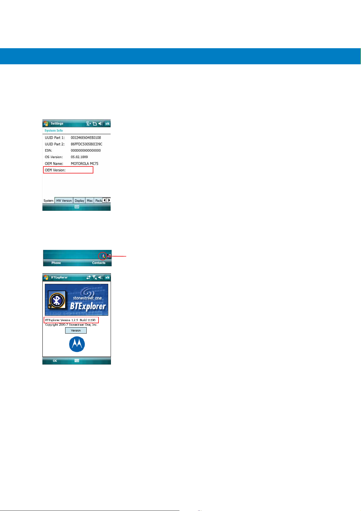
OEM Version
To determine the OEM software version:
Start > Settings > System tab > System Information icon > System tab.
Ta p
01.15.0000
BTExplorer Software
About This Guide xiii
To determine the BTExplorer software version:
BTExplorer icon > Show BTExplorer> File > About.
Ta p
BTExplorer icon
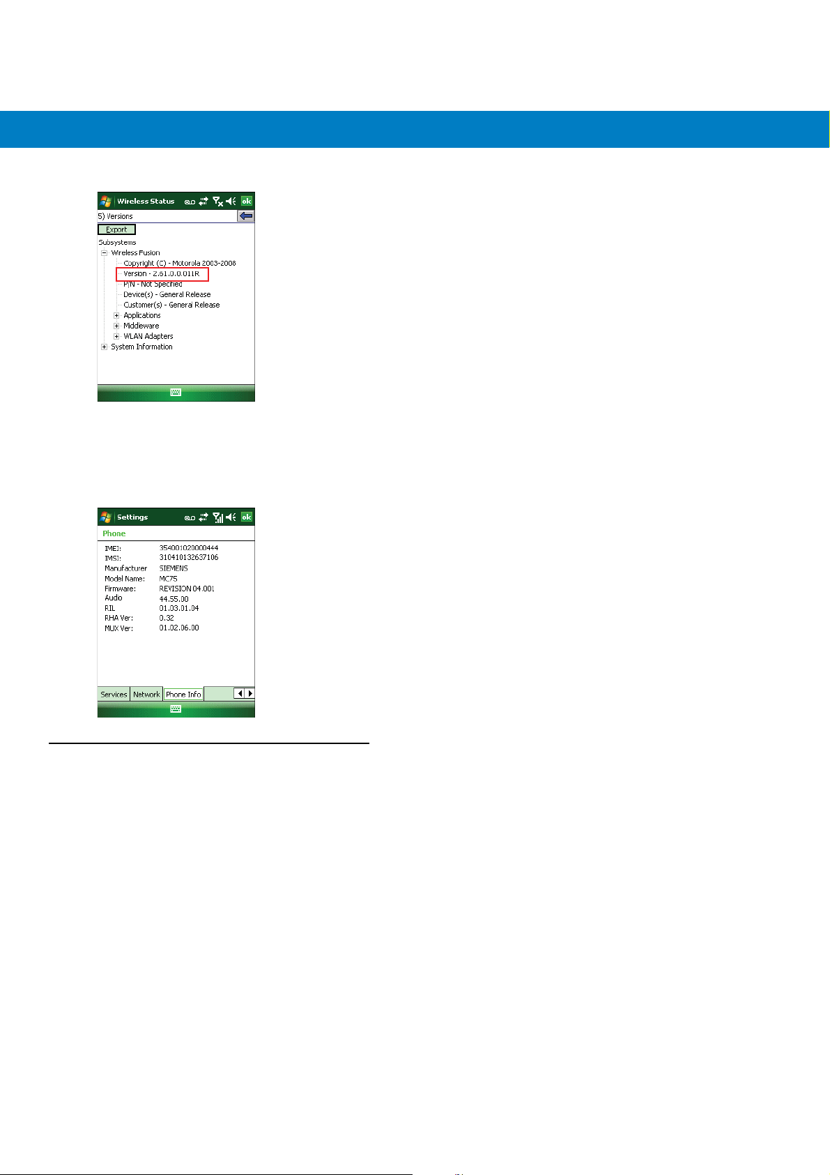
Fusion Software
To determine the Fusion software version:
Wireless Strength icon > Wireless Status > Versi ons .
Ta p
xiv MC55 Integrator Guide
Phone Software
To determine the Phone software version:
Start > Phone > Menu > Options > Version Information tab.
Ta p
Chapter Descriptions
Topics covered in this guide are as follows:
•
Chapter 1, Getting Started provides information on MC55 configurations and accessories, charging the
battery, and resetting the device.
•
Chapter 2, Accessories describes the accessories available for the MC55 and how to set up power
connections and battery charging capabilities, where applicable.
•
Chapter 3, ActiveSync provides instructions on installing ActiveSync and setting up a partnership between
the MC55 and a host computer.
•
Chapter 4, Application Deployment provides information for provisioning and deploying applications to the
MC55.
•
Chapter 5, Wireless Applications describes how to configure the wireless LAN connection.
•
Chapter 6, MC5574 - GSM Configuration explains how to verify MC5504/94 service on an Enhanced Data
rates for Global Evolution (EDGE) wireless network and establish settings.

•
Chapter 7, Maintenance & Troubleshooting includes instructions on cleaning and storing the MC55, and
provides troubleshooting solutions for potential problems during MC55 operation.
•
Appendix A, Technical Specifications includes tables listing the technical specifications for the MC55 and its
accessories.
•
Appendix B, Bluetooth Configuration includes registry settings required for configuring the use of the
Bluetooth stack.
Notational Conventions
The following conventions are used in this document:
•
“EDA” refers to Motorola MC55 family of hand-held computers.
•
Italics are used to highlight the following:
• chapters and sections in this and related documents
• dialog box, window, and screen names
• drop-down list and list box names
• check box and radio button names
• icons on a screen.
About This Guide xv
•
Bold text is used to highlight the following:
• key names on a keypad
• button names on a screen.
•
Bullets (•) indicate:
• action items
• lists of alternatives
• lists of required steps that are not necessarily sequential.
•
Sequential lists (e.g., those that describe step-by-step procedures) appear as numbered lists.
Related Documents
•
MC55 Quick Start Guide, p/n 72-114971-xx.
•
MC55 Windows Mobile 6 Regulatory Guide, p/n 72-108860-xx.
•
MC55 User Guide, p/n 72E-108859-xx.
•
Mobility Services Platform 3.2 User Guide, p/n 72E-100158-xx.
•
AirBEAM Smart Windows CE Client Product Reference Guide, p/n 72-63060-01.
•
Wireless Fusion Enterprise Mobility Suite User Guide for Version 2.61, p/n 72E-113153-02.
•
Microsoft® Applications for Windows Mobile 6 User Guide, p/n 72E-108299-xx.
•
Application Guide for Motorola Enterprise Mobility Devices, p/n 72E-68901-xx.
•
Enterprise Mobility Developer Kits (EMDKs), available at:
http://www.motorola.com/enterprisemobility/support
.
xvi MC55 Integrator Guide
•
Latest ActiveSync software, available at: http://www.microsoft.com.
For the latest version of this guide and all guides, go to: http://www.motorola.com/enterprisemobility/manuals
Service Information
If you have a problem with your equipment, contact Motorola Enterprise Mobility support for your region. Contact
information is available at: http://www.motorola.com/enterprisemobility/contactsupport
When contacting Enterprise Mobility support, please have the following information available:
•
Serial number of the unit (found on manufacturing label)
•
Model number or product name (found on manufacturing label)
•
Software type and version number.
.
.
Manufacturing label
Motorola responds to calls by e-mail, telephone or fax within the time limits set forth in support agreements.
If your problem cannot be solved by Motorola Enterprise Mobility Support, you may need to return your equipment
for servicing and will be given specific directions. Motorola is not responsible for any damages incurred during
shipment if the approved shipping container is not used. Shipping the units improperly can possibly void the
warranty.
If you purchased your Enterprise Mobility business product from a Motorola business partner, contact that business
partner for support.

Chapter 1 Getting Started
Introduction
This chapter provides information about the MC55, accessories, charging, and resetting the MC55.
Unpacking the MC55
Carefully remove all protective material from the MC55 and save the shipping container for later storage and
shipping. Verify that you received the following equipment:
•
MC55
•
Lithium-ion battery
•
Tethered stylus
•
Screen protector, installed on display window
•
Regulatory Guide
•
Quick Start Guide.
Inspect the equipment. If any equipment is missing or damaged, contact the Motorola Enterprise Mobility support
immediately. See Service Information on page xvi for contact information.
Prior to using the MC55 for the first time, remove the protective shipping film that covers the scan window, display
and camera window.
Getting Started
To start using the MC55 for the first time:
•
Install a microSD card (optional)
•
Install the SIM card (MC5574 only)
•
Install the main battery.
1 - 2 MC55 Integrator Guide
•
Charge the MC55.
•
Power on the MC55.
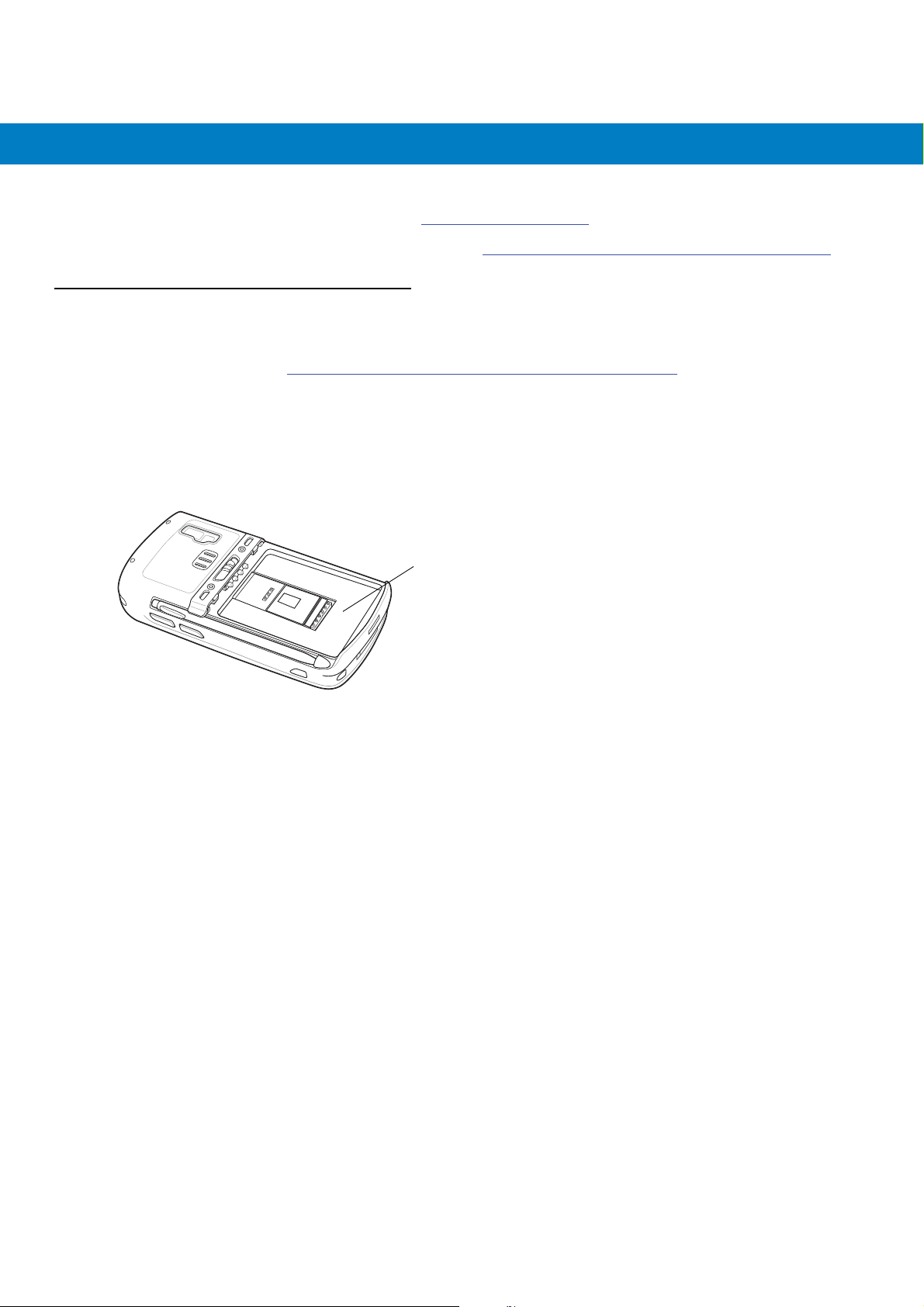
Installing a microSD Card
The microSD card slot provides secondary non-volatile storage. The slot is located under the battery pack. Refer to
the documentation provided with the card for more information, and follow the manufacturer’s recommendations for
use.
CAUTION Follow proper ESD precautions to avoid damaging the SD card. Proper ESD precautions include, but are
not limited to, working on an ESD mat and ensuring that the operator is properly grounded.
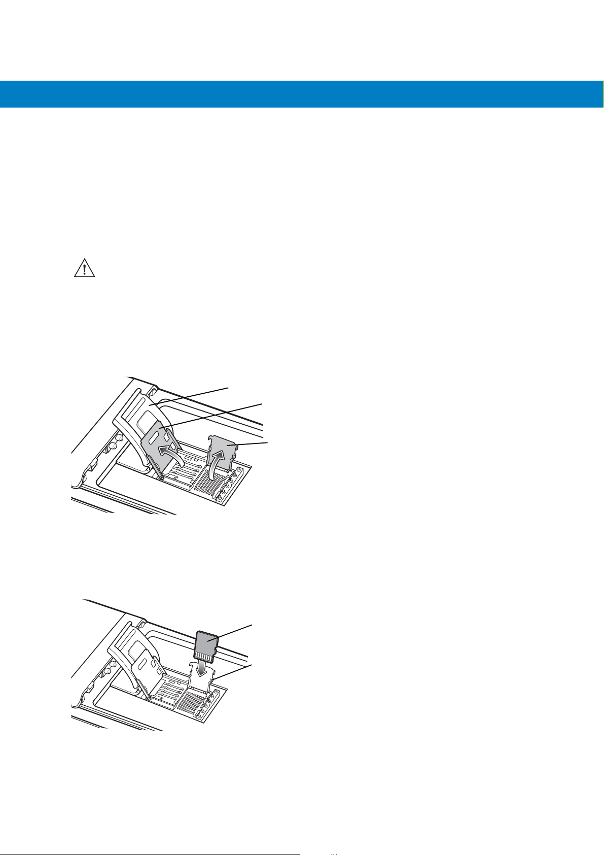
To install the microSD card:
1. Lift rubber access door.
2. Slide the SIM card holder door up to unlock.
3. Lift SIM card holder door.
Rubber access door
SIM card holder door
microSD card holder door
Figure 1-1
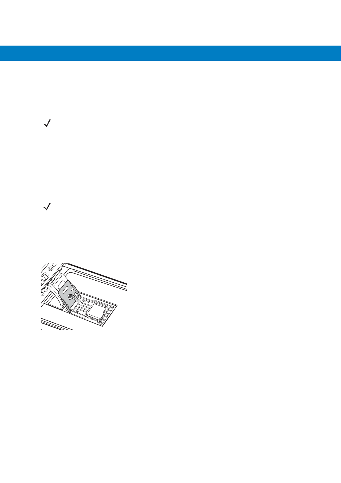
4. Lift microSD card holder door.
5. Insert the microSD card into card holder door ensuring that the card slides into the holding tabs on each side of
Lift SIM Slot Holder Door
the door.
microSD card
Holding tab
Figure 1-2
6. Close the card holder door and push down until it is securely in place.
Insert microSD Card in Holder
Getting Started 1 - 3
7. Close SIM card holder door and slide down to lock into place.
8. Close rubber access door.
Installing the SIM Card
NOTE MC5574 configuration only.
GSM phone service requires a Subscriber Identification Module (SIM) card, or smart card. Obtain the card from the
your service provider. The card can contain the following information:
•
Mobile phone service provider account details.
•
Information regarding service access and preferences.
•
Contact information, which can be moved to Contacts on the MC55.
•
Any additional services to which you have subscribed.
NOTE For more information about SIM cards, refer to the service provider's documentation.
To install the SIM card:
1. Lift rubber access door.
2. Slide the SIM card holder up to unlock.
3. Lift the SIM card holder door.
Figure 1-3
4. Insert the SIM card, as shown in Figure 1-4 ensuring that the card slides into the holding tabs on each side of
Lifting the SIM Cover
the door.
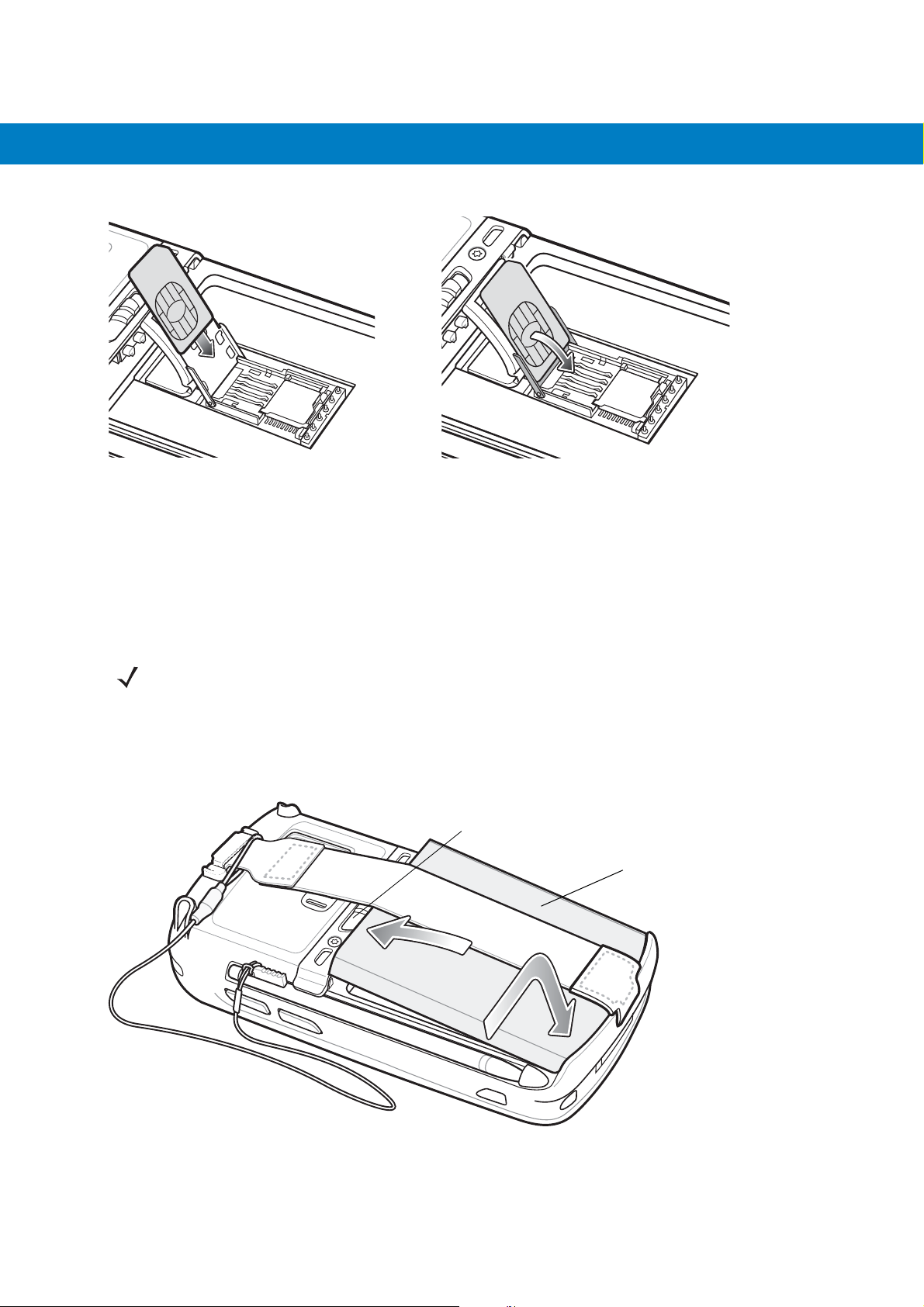
1 - 4 MC55 Integrator Guide
Figure 1-4
5. Close SIM card holder door and slide down to lock into place.
6. Close the rubber access door.
7. Install the battery.
Inserting the SIM Card
Installing the Battery
NOTE The MC55 ships with either a 2400 mAh or 3600 mAh battery. The 2400 mAh battery is shown in this
installation procedure.
To install the battery.
1. Insert the battery, bottom first, into the battery compartment in the back of the MC55.
2. Press the battery down into the battery compartment until the battery release latch snaps into place.
Battery Release Latch
Battery
2
1
Figure 1-5
The MC55 automatically powers up after inserting the battery if the battery has been previously charged.
Inserting the Battery
Getting Started 1 - 5
Charging the Battery
CAUTION Ensure that you follow the guidelines for battery safety described in Battery Safety Guidelines on page 7-2.
Charging the Main Battery
Before using the MC55 for the first time, charge the main battery until the amber Charging/Battery Status LED
remains lit (see Table 1-1 on page 1-5 for charge status indications). To charge the MC55, use a cable or a cradle
with the appropriate power supply. For information about the accessories available for the MC55, see Chapter 2,
Accessories.
For cable and cradle setup and charging procedures see Chapter 2, Accessories for more information.
•
USB Charging Cable
•
Charge Only Cable
•
Single Slot USB Cradle
•
Four Slot Charge Only Cradle
•
Four Slot Ethernet Cradle.
To charge the main battery:
1. Connect the charging accessory to the appropriate power source.
2. Insert the MC55 into a cradle or attach to a cable. The MC55 begins charging. The Charging/Battery Status
LED blinks amber while charging, then turns solid amber when fully charged. See Table 1-1 for charging
indications.
The 2400 mAh battery fully charges in approximately four hours and the 3600 mAh battery fully charges in
approximately six hours.
Table 1-1
Off MC55 is not charging.
Slow Blinking Amber
(1 blink every 2 seconds)
Solid Amber Charging complete.
Fast Blinking Amber
(2 blinks/second)
LED Charge Indicators
Charging/Battery
Status LED
Indication
MC55 is not inserted correctly in the cradle or connected to a power source.
Charger/cradle is not powered.
MC55 is charging.
Note: When the battery is initially inserted in the MC55, the amber LED flashes
once if the battery power is low or the battery is not fully inserted.
Charging error, e.g.:
•
Temperature is too low or too high.
•
Charging has gone on too long without completion (typically eight hours).
Single Blink Amber (when
Power button pressed)
Blinking Amber (when
Power button pressed)
Battery depleted.
Battery over-temperature condition.

1 - 6 MC55 Integrator Guide
Charging Spare Batteries
See Chapter 2, Accessories for information on using accessories to change spare batteries.
Charging Temperature
Charge batteries in temperatures from 0°C to 40°C (32°F to 104°F). Note that charging is intelligently controlled by
the MC55.
To accomplish this, for small periods of time, the MC55 or accessory alternately enables and disables battery
charging to keep the battery at acceptable temperatures. The MC55 or accessory indicates when charging is
disabled due to abnormal temperatures via its LED. See Table 1-1.
Powering On the MC55
After inserting the battery or when turning the MC55 on for the first time, the splash screen displays for about a
minute as the MC55 boots, then the calibration window appears.
Calibrating the Screen
NOTE The Calibration screen can be accessed by pressing Blue key - Backspace key.
To calibrate the screen so the cursor on the touch screen aligns with the tip of the stylus:
1. Remove the stylus from its holder on the side of the MC55.
2. Carefully press and briefly hold the tip of stylus on the center of each target that appears on the screen.
3. Repeat as the target moves around the screen, then tap the screen to continue.
Resetting the MC55
There are three reset functions, warm boot, cold boot and clean boot. A warm boot restarts the MC55 by closing all
running programs. A cold boot also restarts the MC55, and also initializes some drivers. Data saved in flash
memory or a memory card is not lost.
If the MC55 is not functioning properly, perform a warm boot first. If the MC55 still does not respond, perform a cold
boot.
Performing a Warm Boot
Hold down the red Power button for approximately five seconds. As soon as the MC55 starts to boot release the
Power button.
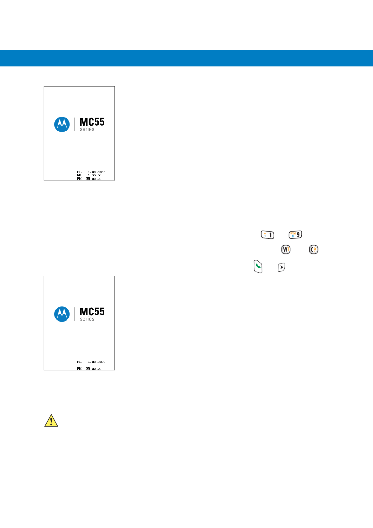
Getting Started 1 - 7
Figure 1-6
Splash Screen (Warm Boot)
Performing a Cold Boot
To perform a cold boot:
•
On a numeric keypad, simultaneously press the red Power button and the and keys.
•
On an alphanumeric keypad, simultaneously press the red Power button and the and keys.
•
On an PIM keypad, simultaneously press the red Power button and the and keys.
Figure 1-7
Splash Screen (Cold Boot)
Performing a Clean Boot
CAUTION A clean boot should only be performed by an authorized system administrator. You must connect the
MC55 to AC power during a clean boot.
Removing AC power from the MC55 during a clean boot may render the MC55 inoperable.
A clean boot resets the MC55 to the factory default settings. All data in the Application folder is retained. You must
download the Clean Boot Package file from the Support Central web site,
http://www.motorola.com/enterprisemobility/support and install on the
To perform a clean boot:
MC55.
1 - 8 MC55 Integrator Guide
1. Download the Clean Boot Package from the Support Central web site. Follow the instructions included in the
package for installing the package onto the
2. Perform a cold boot.
3. Immediately, as soon as the device starts to boot and before the splash screen is visible, press and hold the
left scan button.
4. Insert the MC55 into a powered cradle.
5. The MC55 updates and then re-boots.
6. Calibrate the screen.
Waking the MC55
The wake-up conditions define what actions wake up the mobile computer after it has gone into suspend mode.
The mobile computer can go into suspend mode by either pressing the Power button or automatically by Control
Panel time-out settings. These settings are configurable and the factory default settings are shown in Table 1-2 are
subject to change/update. To access the Wakeup settings, tap Start > Settings > System > Power icon > Wakeup
tab.
MC55.
Table 1-2
AC power is applied. No Yes
Mobile computer is inserted into a cradle. No Yes
Mobile computer is removed from a cradle. No Yes
Mobile computer is connected to a USB device. No Yes
Mobile computer is disconnected from a USB device. No Yes
A key is pressed. No Yes
The scan triggered is pressed. No Yes
The screen is touched. No No
Bluetooth communication Yes Yes
Incoming phone call Yes Yes
Wake-up Default Settings
Condition for Wake-up Power Button Automatic Time-out

Chapter 2 Accessories
Introduction
This chapter provides set up information for the following MC55 accessories:
•
Single Slot USB Cradle - Charges the MC55 main battery and a spare battery. Synchronizes the MC55 with
a host computer through a USB connection.
•
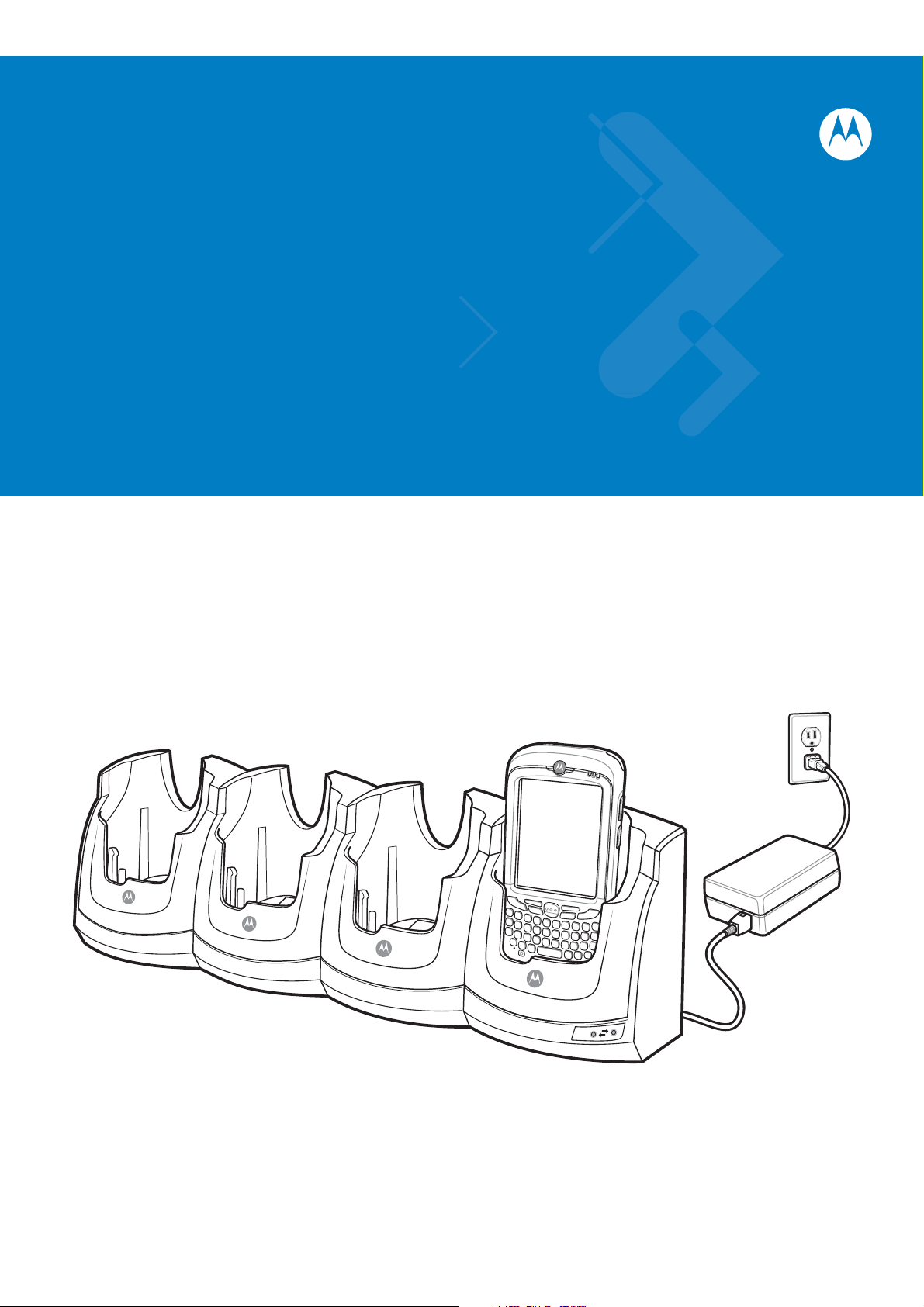
Four Slot Charge Only Cradle - Charges up to four MC55 devices.
•
Four Slot Ethernet Cradle - Charges up to four MC55 devices and connects the MC55 with an Ethernet
network.
•
Four Slot Battery Charger - Charges up to four spare batteries.
•
Vehicle Cradle - Provides secure mounting of the MC55 in a vehicle. Charges the MC55.
•
Cables
• Auto Charge Cable - Plugs into a vehicle cigarette lighter to charge the MC55 while on the road.
• Charge Only Cable - Provides power to the MC55.
• USB Charging Cable - Provides power to the MC55 and USB communication with a host computer.
•
Vehicle Holder - Provides mounting for the MC55 inside a vehicle using a mounted suction cup.

2 - 2 MC55 Integrator Guide
Single Slot USB Cradle
This section describes how to set up and use a Single Slot USB cradle with the MC55. For USB communication
setup procedures see Chapter 3, ActiveSync.
The Single Slot USB cradle:
•
Provides 5.4 VDC power for operating the MC55.
•
Synchronizes information between the MC55 and a host computer. See Chapter 3, ActiveSync for
information on setting up a partnership between the MC55 and a host computer.
•
Charges the MC55’s battery.
•
Charges a spare battery.
Setup
Figure 2-1
USB Port
Single Slot USB Cradle Power and USB Connections
Power Port
AC Line Cord
Power Supply
Charging the MC55 Battery
Connect the cradle to power. Insert the MC55 into the MC55 slot to begin charging.
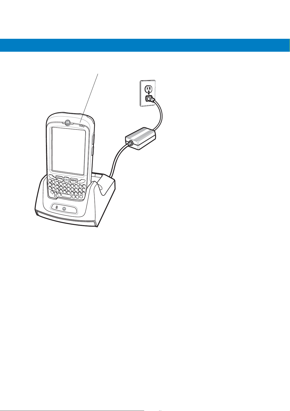
Accessories 2 - 3
Charge Status LED
Figure 2-2
MC55 Battery Charging
2 - 4 MC55 Integrator Guide
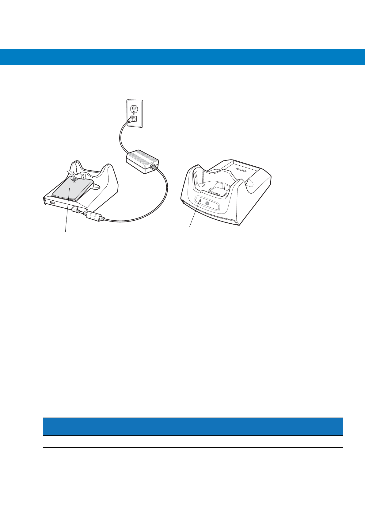
Charging the Spare Battery
Spare Battery
Figure 2-3
Spare Battery Charging
Spare Battery
Charging LED
Battery Charging Indicators
The Single Slot USB cradle charges the MC55’s main battery and a spare battery simultaneously.
The MC55’s Charging/Battery Status LED indicates the status of the battery charging in the MC55. See Table 1-1
on page 1-5 for charging status indications.
The spare battery charging LED on the cradle indicates the status of the spare battery charging in the cradle. See
Table 2-1 for charging status indications.
The 2400 mAh battery fully charges in approximately four hours and the 3600 mAh battery fully charges in
approximately six hours.
Charging Temperature
Charge batteries in temperatures from 0°C to 40°C (32°F to 104°F). Charging is intelligently controlled by the
MC55.
To accomplish this, for small periods of time, the MC55 or accessory alternately enables and disables battery
charging to keep the battery at acceptable temperatures. The MC55 or accessory indicates when charging is
disabled due to abnormal temperatures via its LED. See Table 1-1 on page 1-5 and Table 2-1.
Table 2-1
Slow Blinking Amber Spare battery is charging.
Spare Battery LED Charging Indicators
Spare Battery LED
(on cradle)
Indication

Accessories 2 - 5
Table 2-1
Solid Amber Spare battery is fully charged.
Fast Blinking Amber Charging error.
Off Not charging.
Spare Battery LED Charging Indicators (Continued)
Spare Battery LED
(on cradle)
Indication

2 - 6 MC55 Integrator Guide
Four Slot Ethernet Cradle
This section describes how to set up and use a Four Slot Ethernet cradle with the MC55.
The Four Slot Ethernet cradle:
•
Provides 5.4 VDC power for operating the MC55.
•
Connects the MC55 (up to four) to an Ethernet network.
•
Simultaneously charges up to four MC55s.
You cannot ActiveSync using the Four Slot Ethernet cradle. To ActiveSync with a host computer, use the Single
Slot USB/Serial cradle, USB Charging cable or Serial Charging cable.
Setup
Connect the Ethernet cradle to a power source and to an Ethernet switch, router, or hub, or a port on the host
device.
Ethernet Port 1
Power Port
Ethernet Port
Ethernet Switch,
Router, or Hub
Connection
Figure 2-4
Four Slot Ethernet Cradle Connection
Daisychaining Ethernet Cradles
Daisychain up to four Ethernet cradles to connect several cradles to an Ethernet network. Use either a straight or
crossover cable. Daisy-chaining should not be attempted when the main Ethernet connection to the first cradle is
10 Mbps as throughput issues will almost certainly result.
To daisychain more than one Ethernet cradle:
1. Connect power to each Ethernet cradle to daisychain.
2. Connect an Ethernet cable to Port 1 of the first cradle as shown in Figure 2-4.
3. Connect a second Ethernet cable between Port 2 of the first cradle, and Port 1 of the second cradle.
4. Connect additional cradles as described in Step 3.

Accessories 2 - 7
Figure 2-5
Speed LED
Ethernet Port 2
Daisychaining Four Slot Ethernet Cradles
Link LED
Ethernet Port 1
Ethernet Cradle Drivers
The MC55 includes Ethernet cradle drivers that initiate automatically when you place the MC55 in a properly
connected Four Slot Ethernet cradle. After inserting the MC55, configure the Ethernet connection:
1. Ta p Start > Settings > Connections tab >WiFi icon. The Configure Network Adapters window appears.
Figure 2-6
2. In the My network card connects to: drop-down list, select the appropriate connection.
3. In the Tap an adapter to modify settings: list, select USB/Ethernet Series Adapter.
Configure Network Adapters Window

2 - 8 MC55 Integrator Guide
Figure 2-7
4. In the IP address window, select the appropriate radio button:
•
IP Address Tab
Use server-assigned IP address
or
•
Use specific IP address. Enter the IP address, Subnet mask, and Default gateway, as needed.
5. Tap the Name Servers tab.
Figure 2-8
Name Servers Tab
6. Enter the appropriate DNS, Alt DNS, WINS, and Alt WINS server addresses.
7. Ta p ok.
Figure 2-9
8. Ta p ok to confirm the setup.
9. Ta p ok to exit.
Adapters Dialog Box

Accessories 2 - 9
Charging and Communication
Insert the MC55 into a slot to begin charging.
LED Charging Indicators
Charge LED
The MC55’s charge LED shows the status of the battery charging in the MC55. See Table 1-2 on page 1-7 for
charging status indications.
The 2400 mAh battery fully charges in approximately four hours and the 3600 mAh battery fully charges in
approximately six hours.
Speed LED
The cradle’s green Speed LED lights to indicate that the transfer rate is 100 Mbps. When it is not lit it indicates that
the transfer rate is 10Mbps.
Link LED
The cradle’s yellow Link LED blinks to indicate activity, or stays lit to indicate that a link is established. When it is
not lit it indicates there is no link.
Charging Temperature
Charge batteries in temperatures from 0°C to 40°C (32°F to 104°F). Charging is intelligently controlled by the
MC55.
To accomplish this, for small periods of time, the MC55 alternately enables and disables battery charging to keep
the battery at acceptable temperatures. The MC55 indicates when charging is disabled due to abnormal
temperatures via its LED. See Table 1-2 on page 1-7.

2 - 10 MC55 Integrator Guide
Four Slot Charge Only Cradle
This section describes how to set up and use a Four Slot Charge Only cradle with the MC55.
The Four Slot Charge Only cradle:
•
Provides 5.4 VDC power for operating the MC55.
•
Simultaneously charges up to four MC55s.
You cannot ActiveSync using the Four Slot Charge Only cradle. To ActiveSync with a host computer, use the
Single Slot USB cradle.
Setup
Connect the Four Slot Charge Only cradle to a power source.
Figure 2-10
Four Slot Charge Only Cradle Connection
Charging Temperature
Charge batteries in temperatures from 0°C to 40°C (32°F to 104°F). Charging is intelligently controlled by the
MC55.
To accomplish this, for small periods of time, the MC55 alternately enables and disables battery charging to keep
the battery at acceptable temperatures. The MC55 indicates when charging is disabled due to abnormal
temperatures via its LED. See Table 1-1 on page 1-5.

Wall Mount Bracket
Mounting Screw (4)
Mounting Tab (2)
Mounting Slot
Mounting Screw (2)
Four Slot
Cradle Bottom
Use the optional Wall Mount Bracket to mount a four slot cradle to a wall. To attach the Wall Mount Bracket:
1. Use the Wall Mount Bracket as a template and mark the locations of the four mounting screws.
NOTE Use fasteners appropriate for the type of wall and the Wall Mount Bracket mounting slots. The Wall Mount
Bracket mounting slots are designed for a fastener with a #8 pan head. Fasteners must be able to hold a
minimum of 4.9 Kg (10.8 lbs).
2. Mount the fasteners to the wall. The screw heads should protrude about a half of an inch from the wall.
3. Slip the Wall Mount Bracket over the screw heads and slide the bracket down over the screw heads.
4. Tighten the screws to secure the bracket to the wall.
Accessories 2 - 11
Figure 2-11
Wall Mount Bracket
To mount a four slot cradle:
1. Screw the supplied screws into the bottom of the four slot cradle. The screw heads should protrude about a
quarter of an inch from the cradle.
Figure 2-12
2. Align the Wall Mount Bracket mounting tabs with the mounting slots in the back of the four slot cradle. Slip the
two mounting tabs into mounting slots.
Cradle Mounting Screws

2 - 12 MC55 Integrator Guide
3. Swing the four slot cradle down onto the mounting bracket and align the mounting screws so that they fit into
the screw slots.
Wall Mount
Bracket
Screw Slots
Power Supply
Well
Figure 2-13
4. Tighten the mounting screws to secure the four slot cradle to the bracket.
Figure 2-14
5. Connect power (see Figure 2-10 on page 2-10). The power supply should be located in the power supply well.
Wall Mount Bracket
Mounting Screws

VCD5500 Vehicle Cradle
1
This section describes how to set up and use a VCD5500 vehicle cradle with the MC55.
Once installed in a vehicle, the cradle:
•
holds the MC55 securely in place
•
provides power for operating the MC55
•
re-charges the battery in the MC55.
Requirements
For mounting:
•
four #8-32 self-locking nuts
•
four #8 washers
•
a drill with a #6 drill bit (.204”).
For power connection:
Accessories 2 - 13
•
power input cable (included), p/n 25-61987-01R
•
UL Listed in-line fuse rated 250V, 5A (included), must be used if not connecting to vehicle’s fuse panel
•
in-line fuse holder (included), must be used if not connecting to vehicle’s fuse panel.
Connector Pin-Outs
Table 2-2
1 Chassis ground (Black Wire)
2 Chassis ground (Bare Wire)
3 V+ (Red Wire)
4 V+ (Red Wire)
Power Input Cable
Pin Signal
Connector on Power Cable
CAUTION ROAD SAFETY - Do not use the MC55 while driving. Park the vehicle first. Always ensure the MC55 is
fully inserted into the cradle. Do not place it on the seat or where it can break loose in a collision or
sudden stop. Lack of proper insertion may result in property damage or personal injury. Motorola, Inc. is
not responsible for any loss resulting from the use of the products while driving. Remember: Safety
comes first.
Mounting the Cradle
CAUTION Only mount the Vehicle Cradle in a vertical position with the release level at the top or in a horizontal position
with the MC55 display facing up. Never mount the vehicle cradle on the side or upside down or on a wall that
can be subject to impact or collision of greater than 40Gs, in accordance with SAE J1455 Section 4.10.3.5

2 - 14 MC55 Integrator Guide
1. Select a mounting location for the cradle. It should be flat, and must provide adequate support for the cradle.
NOTE If using the GPS functionality of the MC55 mobile computer, ensure that the vehicle cradle is positioned so that
the MC55 has a clear unobstructed view of the sky.
2. Prepare the mounting surface to accept four #8-32 studs, using the mounting template below. Drill four holes
with a #6 drill bit.
1.2”
1.5”
Figure 2-15
3. Position the cradle on the mounting surface.
4. Fasten it using four #8 washers and four #8-32 self-locking nuts.
Vehicle Cradle Mounting Template
CAUTION Do not install a VCD5500 Vehicle Cradle on or near an air bag cover plate or within an aerobic zone. Also, do
not install it in a location that affects vehicle safety or driveability.
Power Connection
Please read all of the following instructions before beginning.
WARNING! A properly trained technician must perform the power connection. Improper connection can damage
your vehicle, cradle or MC55. Refer to the vehicle’s Owner’s Manual for instructions for removing
power.
To connect the cradle to power:
CAUTION When setting up connection for this cradle, only use the power input cable provided with this cradle.
1. Locate the vehicle power source.
NOTE The ideal location for connecting the vehicle cradle power input cable would be an accessory output in your
vehicle’s fuse panel. The vehicle cradle should be added to a circuit with a maximum load capacity for the
cradle and the original circuit. Refer to the vehicle’s Owner’s Manual for identification of the circuit.
If a fused output is not available, the vehicle cradle must be installed with the provided in-line fuse holder and
UL Listed 5A fuse. The fuse protects the vehicle from an electrical short on the power line to the cradle.
To use the cradle to charge the MC55 and spare battery, when the vehicle’s ignition is off, connect the cradle to
unswitched power.
Accessories 2 - 15
2. Route the power input cable from the cradle’s power port to the connection point for the vehicle’s power
source.
CAUTION The means of routing and securing the power input cable from the cradle through to the vehicle power
source is extremely important. Hazards associated with improper wiring can be severe. To avoid
unintentional contact between the wire and any sharp edges, provide the cable with proper bushings and
clamping where it passes through openings. If the wire is subjected to sharp surfaces and excess engine
vibration, the wiring harness insulation can wear away, causing a short between the bare wire and chassis.
This can start a fire.
To avoid any mishaps, all wiring should be routed away from moving parts, high temperature areas and any
contaminants.
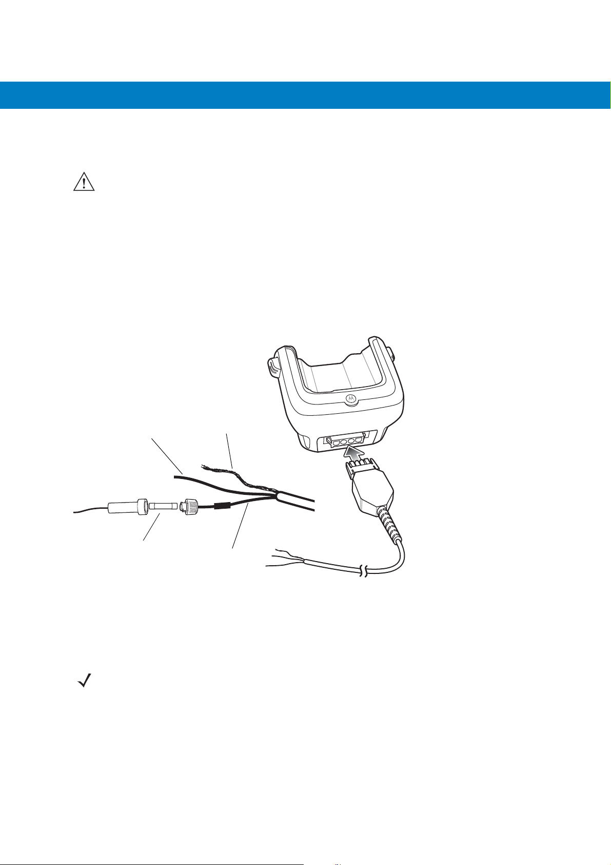
3. When using the supplied in-line fuse holder (which must be used if not connecting to vehicle’s fuse panel):
a. Ensure the fuse holder contains a 5A UL Listed slow-blow fuse.
b. Splice the fuse holder to the end of the red V+ wire, as shown above. Make the distance from the fuse to
the power connection point as short as possible.
Shield Wire
Ground
Wire (black)
5A Fuse and
Fuse Holder
Figure 2-16
4. Prepare the cable termination.
a. Red wire: connect to a +12/24 V vehicle power source.
b. Black wire and Shield wire: connect to vehicle ground wire or chassis ground.
Vehicle Cradle Power Connection
NOTE How the cable terminates depends on the vehicle. If the vehicle has a power output connector, then you must
attach a mating connector to the end of the power cable. You may be able to connect to a fuse panel with a
simple blade terminal or commercially available connector. Consult the vehicle Owner’s Manual for information
on how to access the power supply in the vehicle.
(bare wire)
V+ Power (red)
5. Connect the power input cable into the power port on the cradle.
To see if the cradle has power, insert the MC55. The Charging LED on the MC55 blinks slowly to indicate charging
and turns solid amber when the battery is completely charged. See Table 1-1 on page 1-5 for other indications.

2 - 16 MC55 Integrator Guide
Charging the MC55 Battery
Insert the MC55 into the vehicle cradle to begin charging. A click indicates that the MC55 button release locking
mechanism is enabled and the MC55 is locked in place.
Release Lever
Figure 2-17
MC55 Battery Charging
CAUTION Ensure the MC55 is fully inserted in the cradle. Lack of proper insertion may result in property damage or
personal injury. Motorola, Inc. is not responsible for any loss resulting from the use of the products while
driving.
Removing the MC55
To remove the MC55, press the release levers on the cradle and pull the MC55 up and out of the cradle.
Release Lever
Figure 2-18
Removing the MC55

Accessories 2 - 17
Battery Charging Indicators
The MC55’s charge LED indicates the status of the battery charging in the MC55. See Table 1-1 on page 1-5 for
charging status indications.
The 2400 mAh battery fully charges in approximately four hours and the 3600 mAh battery charges in
approximately six hours.
Charging Temperature
Charge batteries in temperatures from 0°C to 40°C (32°F to 104°F). Charging is intelligently controlled by the
MC55.
To accomplish this, for small periods of time, the MC55 alternately enables and disables battery charging to keep
the battery at acceptable temperatures. The MC55 indicates when charging is disabled due to abnormal
temperatures via its LED. See Table 1-1 on page 1-5.

2 - 18 MC55 Integrator Guide
Battery Charging
LEDs (4)
Battery
Four Slot Battery Charger
This section describes how to use the Four Slot Battery Charger to charge up to four MC55 spare batteries.
Spare Battery Charging
1. Connect the charger to a power source.
2. Insert the spare battery into a spare battery charging well and gently press down on the battery to ensure
proper contact.
Figure 2-19
Battery Charging Indicators
An amber LED is provided for each battery charging well. See Table 2-3 for charging status indications. The 2400
mAh battery fully charges in approximately four hours and the 3600 mAh battery charges in approximately six
hours.
Charging Temperature
Charge batteries in temperatures from 0°C to 40°C (32°F to 104°F). Charging is intelligently controlled by the
charger in order to ensure safe operation and optimize long-term battery life.
To accomplish this, for small periods of time, the charger alternately enables and disables battery charging to keep
the battery at acceptable temperatures. The charger indicates when charging is disabled due to abnormal
temperatures via its LED. See Table 2-3.
Four Slot Spare Battery Charger

Accessories 2 - 19
Table 2-3
Off No spare battery in slot; spare battery not placed correctly; cradle is not powered.
Fast Blinking Amber Error in charging; check placement of spare battery.
Slow Blinking Amber Spare battery is charging.
Solid Amber Charging complete.
Spare Battery LED Charging Indicators
LED Indication

2 - 20 MC55 Integrator Guide
Cables
This section describes how to set up and use the cables. The cables are available with a variety of connection
capabilities.
The following communication/charge cables are available:
•
USB Charging cable
•
Charge Only cable
•
Auto Charge cable.
USB Charging Cable
The USB Charging cable provides the MC55 with operating and charging power when used with the Motorola
approved power supply and AC line cord and synchronize information between the MC55 and a host computer.
Figure 2-20
USB Charging Cable
Charge Only Cable
The Charge Only cable provide the MC55 with operating and charging power when used with the Motorola
approved power supply.

Accessories 2 - 21
Figure 2-21
Charge Only Cable
Auto Charge Cable
The Auto Charge cable plugs into a vehicle cigarette lighter and provide the MC55 with operating and charging
power.
Figure 2-22
Auto Charge Cable
Connecting to the MC55
1. If required, connect the cable power input connector to the Motorola approved power source.
2. Slide the bottom of the MC55 into the connector cup end of the cable until the MC55 is firmly seated in the cup.
3. Slide the two locking tabs up until they both lock into position.

2 - 22 MC55 Integrator Guide
Locking Tab
Figure 2-23
4. To remove, slide the two locking tab down and remove the cable from the MC55.
Cable Cup Locking Tabs
Battery Charging Indicators
The MC55 amber Charge LED indicates the MC55 battery charging status. The 2400 mAh battery charges in less
than four hours and the 3600 mAh battery charges in less than six hours. See Table 1-1 on page 1-5 for charging
status indications.
Charging Temperature
Charge batteries in temperatures from 0°C to 40°C (32°F to 104°F). Charging is intelligently controlled by the
MC55.

Accessories 2 - 23
To accomplish this, for small periods of time, the MC55 alternately enables and disables battery charging to keep
the battery at acceptable temperatures. The MC55 indicates when charging is disabled due to abnormal
temperatures via its LED. See Table 1-1 on page 1-5.

2 - 24 MC55 Integrator Guide
Vehicle Holder
WARNING! Some countries prohibit the mounting of any electronic device in any location on the vehicle
dashboard. Be sure to check your local laws acceptable mounting areas before installing the
auto mounting kit.
Installation Reminders
Figure 2-24
•
•
•
•
•
Vehicle Holder Mounting
Do not mount the vehicle holder where it will obscure the driver’s view of the road.
Do not mount the vehicle holder near the driver seat air bag deployment area.
Do not place the MC55 on top of the dashboard or anywhere without securing it in the vehicle holder.
Do not mount the vehicle holder near the passenger seat air bag deployment area.
Install the vehicle holder on the surface of your vehicle that is reasonably flat and free of dirt and oil.
Device Mounting Precautions
•
Some countries prohibit the mounting of any electronic device in any location on the vehicle dashboard. Be
sure to check your local laws acceptable mounting areas before installing the vehicle holder.
•
The heating and cooling cycle of a vehicle’s interior will in some cases loosen the adhesion of the suction
cup. Check the vacuum seal of the vehicle mount kit for adequate adhesion each time you use the unit, and
reinstall if necessary.
•
If the vehicle holder has problems staying on, clean the plastic suction cup with alcohol, then reinstall.
Installation
Install the vehicle mount on the surface of your vehicle that is reasonably flat and free of dirt and oil. Clean the
mounting surface with a glass cleaner and a clean cotton cloth. Install the vehicle mount on the windshield or other
flat car surface using the supplied mounting disc.

Assembly
1. Insert the vehicle holder’s cradle plate to the holes on the back of the cradle.
2. Push the cradle down until both parts are engaged.
Windshield Installation
1. Fix the suction cup mount to the selected area with the suction lever facing up.
Suction Cup Mount
Cradle Plate
Cradle
Accessories 2 - 25
Figure 2-25
2. Flip the lever down to create a vacuum between the suction cup and the mounting surface.
3. Make sure that the suction bond is strong enough before proceeding to the next step.
4. Slide the MC55 into the cradle.
Windshield Installation

2 - 26 MC55 Integrator Guide
Locking Tab
Figure 2-26
5. Connect the auto charger cable to the MC55 and slide the two locking tabs up to secure the cable cup to the
Insert MC55 into Vehicle Holder
MC55.
6. Connect the other end to the cigarette lighter socket.
The LED indicator on the right side of the touch screen lights up orange during charging.
NOTE Prior to removing the MC55 from the vehicle holder, disconnect the auto-charge cable from the MC55.
Flat Surface Installation
1. Remove the plastic sheet on the bottom of the mounting disc.
2. Place the disc, sticky side down, on a clean flat surface.
Figure 2-27
Mounting Disc
3. Fix the suction cup mount to the disc with the suction lever facing up.
4. Flip the lever down to create a vacuum between the suction cup and the disc.

5. Make sure that the suction bond is strong enough before proceeding to the next step.
6. Slide the MC55 into the cradle.
Accessories 2 - 27
Figure 2-28
7. Connect the auto charger cable to the MC55 and slide the two locking tabs up to secure the cable cup to the
Vehicle Holder Mounted on Flat Surface
MC55.
8. Connect the other end to the cigarette lighter socket.
The LED indicator on the right side of the touch screen lights up orange during charging.

2 - 28 MC55 Integrator Guide

Chapter 3 ActiveSync
Introduction
To communicate with various host devices, install Microsoft ActiveSync (version 4.5 or higher) on the host
computer. Use ActiveSync to synchronize information on the mobile computer with information on the host
computer. Changes made on the mobile computer or host computer appear in both places after synchronization.
NOTE When a mobile computer with Windows Mobile 6.1 is connected to a host computer and an ActiveSync
connection is made, the WLAN radio (if applicable) is disabled. This is a Microsoft security feature to prevent
connection to two networks at the same time.
ActiveSync software:
•
Allows working with mobile computer-compatible host applications on the host computer. ActiveSync
replicates data from the mobile computer so the host application can view, enter, and modify data on the
mobile computer.
•
Synchronizes files between the mobile computer and host computer, converting the files to the correct
format.
•
Backs up the data stored on the mobile computer. Synchronization is a one-step procedure that ensures the
data is always safe and up-to-date.
•
Copies (rather than synchronizes) files between the mobile computer and host computer.
•
Controls when synchronization occurs by selecting a synchronization mode, e.g., set to synchronize
continually while the mobile computer is connected to the host computer, or set to only synchronize on
command.
•
Selects the types of information to synchronize and control how much data is synchronized.
Installing ActiveSync
To install ActiveSync on the host computer, download version 4.5 or higher from the Microsoft web site at
http://www.microsoft.com. Refer to the installation instructions included with the ActiveSync software.

3 - 2 MC55 Integrator Guide
Mobile Computer Setup
NOTE Microsoft recommends installing ActiveSync on the host computer before connecting the mobile computer.
The mobile computer by default is set up to communicate through a USB connection. Chapter 2, Accessories
provides the accessory setup and cable connection information for use with the mobile computer. The mobile
computer communication settings must be set to match the communication settings used with ActiveSync.
1. On the mobile computer tap Start > Programs > ActiveSync icon. The ActiveSync window appears.
Figure 3-1
2. Ta p Menu > Connections.
3. Select the connection type from the drop-down list.
4. Ta p OK to exit the Connections window and tap OK to exit the ActiveSync window.
5. Proceed with installing ActiveSync on the host computer and setting up a partnership.
ActiveSync Window

Setting Up an ActiveSync Connection on the Host Computer
To start ActiveSync:
1. Select Start > Programs > Microsoft ActiveSync on the host computer. The ActiveSync Window displays.
ActiveSync 3 - 3
Figure 3-2
2. In the ActiveSync window, select File > Connection Settings. The Connection Settings window appears.
Figure 3-3
3. Select Allow USB connections checkbox.
4. Select the Show status icon in Taskbar check box.
ActiveSync Window
NOTE Assign each mobile computer a unique device name. Do not try to synchronize more than one mobile
computer to the same name.
Connection Settings Window
5. Select OK to save any changes made.

3 - 4 MC55 Integrator Guide
Synchronization with a Windows Mobile 6.1 Device
NOTE When a mobile computer with Windows Mobile 6.1 is connected to a host computer and an ActiveSync
connection is made, the WLAN radio (if applicable) is disabled. This is a Microsoft security feature to prevent
connection to two networks at the same time.
To synchronize with a Windows Mobile 6.1 device:
1. If the Get Connected window does not appear on the host computer, select Start > All Programs > Microsoft
ActiveSync
.
Figure 3-4
2. Click Next.
Figure 3-5
3. Select the check box to synchronize with a server running Microsoft Exchange if applicable.
4. Click Next.
Synchronization Setup Wizard Window
Synchronization Directly With a Server Window
ActiveSync 3 - 5
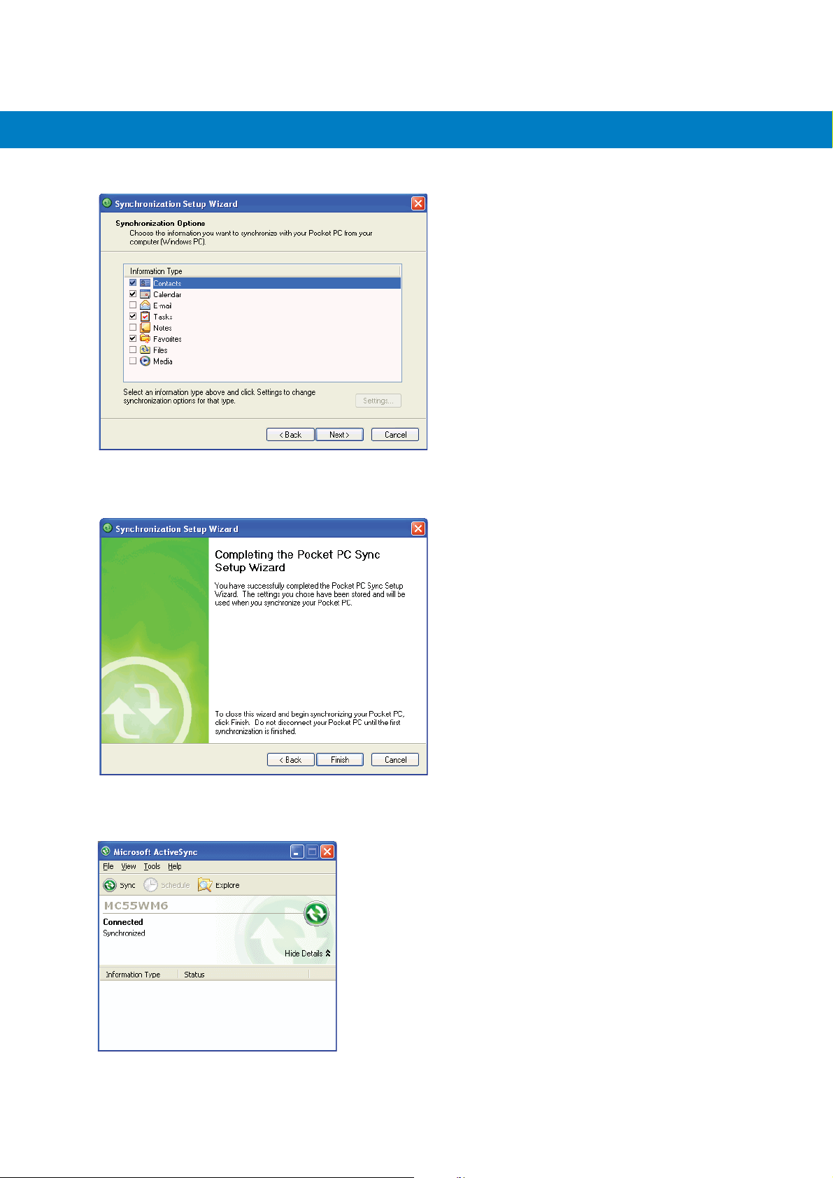
Figure 3-6
5. Select the appropriate settings and click Next.
Figure 3-7
6. Click Finish.
Synchronization Option Window
Wizard Complete Window
Figure 3-8
ActiveSync Connected Window

3 - 6 MC55 Integrator Guide
During the first synchronization, information stored on the mobile computer is copied to the host computer. When
the copy is complete and all data is synchronized, the mobile computer can be disconnect from the host computer.
NOTE The first ActiveSync operation must be performed with a local, direct connection. Windows Mobile retains
partnerships information after a cold boot.
For more information about using ActiveSync, start ActiveSync on the host computer, then see ActiveSync Help.

Chapter 4 Application Deployment
Introduction
This chapter describes features in Windows Mobile including new security features, how to package applications,
and procedures for deploying applications onto the MC55.
Security
The MC55 implements a set of security policies that determine whether an application is allowed to run and, if
allowed, with what level of trust. To develop an application, you must know the security configuration of the device,
and how to sign an application with the appropriate certificate to allow the application to run (and to run with the
needed level of trust).
Application Security
Application security controls the applications that can run on the MC55.
•
Trusted - All applications must be digitally signed by a certificate on the MC55.
•
Prompted - User is prompted to allow unsigned applications to run.
•
Open - All applications run.
Developers can include their own certificates and provision the device to “trusted.”
Digital Signatures
Digital signatures provide a way to authenticate the author of EXEs, DLLs, and packages. Digitally signed
applications give users confidence that an application comes from where they think it comes from. For example, if
an end-user downloads an update package from the internet that is digitally signed with Motorola's software
certificate, they are assured that the package is authentic and that it was created by Motorola. By enforcing the use
of digital signatures, users can also prevent malicious applications from executing on the MC55. For example,
users can provision the MC55 to only execute “trusted” applications (digitally signed).
Motorola ships all Windows Mobile 6 based products in an “open” state, which means all signed and unsigned
applications should work. However, customers can still reconfigure their MC55 to operate in the “trusted” mode.

4 - 2 MC75 Integrator Guide
This means that only applications signed with a certificate from the Privileged Execution Trust Certificate Store can
run.
To support the broadest number of deployments, third-party software developers should perform the following
when releasing software for a Windows Mobile 6 devices:
•
Sign all their EXEs & DLLs with their private key
•
Provide the corresponding public certificate to end-users so that it can be installed into Privileged Execution
Trust Certificate Store.
If the software is installed via a .CAB file, developer should also:
•
Sign the .CAB file with their private key
•
Provide the corresponding public certificate to end-users so that it can be installed into SPC Certificate Store.
Locking Down a Mobile Computer
Like most configuration options in Windows Mobile, security settings are set via XML provisioning. For example, to
enforce the “trusted” model and only allow applications signed with a privileged certificate to run, use the following
provisioning document:
<wap-provisioningdoc>
<characteristic type=”SecurityPolicy”>
<!-- Disallow unsigned apps -->
<parm name= “4102” value= “0”/>
<!-- No Prompt -->
<parm name= “4122” value= “1”/>
</characteristic>
</wap-provisioningdoc>
For more information on various security options, refer to the Security Policy Settings topic in the latest Windows
Mobile documentation.

Application Deployment 4 - 3
Installing Certificates
Use XML provisioning to query and delete certificates from certificate stores. To add a new certificate the Privileged
Execution Trust Certificate Store, use the following sample provisioning document:
<wap-provisioningdoc>
<characteristic type= “CertificateStore”>
<characteristic type= “Privileged Execution Trust Authorities”>
<characteristic type= “657141E12FA45786F6A57CA6464032D4B3A55475”>
<parm name= “EncodedCertificate” value= “
This is sample text. This is sample text. This is sample text. This is sample text.
This is sample text. This is sample text. This is sample text. This is sample text.
This is sample text. This is sample text. This is sample text. This is sample text. = “/>
</characteristic>
</characteristic>
</characteristic>
</wap-provisioningdoc>
To create your own provisioning document with real certificate information:
1. Obtain a certificate from a security provider such as VeriSign.
2. Double-click on the certificate file (.CER) to open it.
3. Click on the Details tab and locate the Thumbprint field.
4. Copy the contents of the Thumbprint field and replace the value in the XML example above.
5. Click the Copy to File… button.
6. Click Next to start the Certificate Export Wizard.
7. Select Base-64 encoded X.509 (.CER) and then click Next.
8. Set the File Name to CertOutput.xml and click Next.
9. Click Finish to export the certificate.
10. Open the exported file, CertOutput.xml, in a text editor (i.e., NotePad).
11. Copy the contents of the file (excluding the first line, last line, and CR/LF) and replace the value of the
“EncodedCertificate” parameter in the xml example above.
Device Management Security
You can control access to certain device settings and security levels, such as installing applications and changing
security settings. Refer to the Windows Mobile Version 6 Help file for information on device management security.
Remote API Security
The Remote API (RAPI) enables applications that run on a desktop to perform actions on a remote device. RAPI
provides the ability to manipulate the file system on the remote device, including the creation and deletion of files
and directories. By default, Motorola ships with RAPI in the restricted mode. Certain tools, such as RAPIConfig,

4 - 4 MC75 Integrator Guide
may not work properly. Refer to the Windows Mobile Version 6 Help file for finding information on Remote API
security policies.
Packaging
NOTE Applications compiled for Windows Mobile 6 are not backward-compatible with previous versions.
Packaging combines an application's executable files into a single file, called a package. This makes it easier to
deploy and install an application to the MC55. Package new applications and updates, such as new DLL files, as
CAB files, then deploy them to devices. Refer to the Microsoft Windows Mobile 6 Help file for information on CAB
files.
Deployment
To install applications onto the MC55, developers package the application and all required files into a CAB file, then
load the file onto the MC55 using one of the following options:
•
Microsoft ActiveSync 4.5 or higher
•
Storage Card
•
MSP 3.2
•
AirBEAM
•
Image Loader Image (for updating the operating system).
Refer to the Microsoft Windows Mobile 6 Help file for information on CAB files.
Installation Using ActiveSync
To install an application package:
•
Connect the MC55 to a host computer using ActiveSync. See Chapter 3, ActiveSync for more information.
•
Locate the package file on the host computer.
•
In ActiveSync on the host computer, open Explorer for the MC55.
•
Copy the CAB file from the host computer to the \temp directory on the MC55.
•
On the MC55, navigate to the \temp directory.
•
Tap on the application CAB file. The application installs on the MC55.
Installation Using Storage Card
To install an application package:
•
Copy the package CAB file to a microSD storage card using an appropriate storage card reader.
•
Install the storage card into the MC55. See Installing a microSD Card on page 1-2 for more information.
•
On the MC55, open File Explorer.

Application Deployment 4 - 5
•
Open the Storage Card directory.
•
Tap the package CAB file. The application installs on the MC55.
Installation Using AirBEAM
The AirBEAM Smart Client provides backward-compatible legacy AirBEAM functionality and backward-compatible
legacy MSP 2.x Level 2 Agent functionality.
Refer to the AirBEAM Smart Windows CE Client Product Reference Guide, p/n 72-63060-xx, for instructions for
AirBEAM Smart client.
MSP 3.2
The MSP 3 Client Software is a set of software components that come pre-installed on the MC55. The MSP 3
Client software consists of the following components:
The RD Client provides support for MSP 3 Staging functionality, provides support for the MSP 3 Legacy Staging
process, and provides support for backward-compatible legacy MSP 2.x Legacy Staging functionality.
The MSP 3 Agent provides MSP 3 Provisioning functionality and Control functionality when used with MSP 3.2
Control Edition.
Refer to the Mobility Services Platform 3.2 User’s Guide, p/n 72E-100158-xx, for instructions for using the Rapid
Deployment and MSP3 Agent clients.
Update Loader Image
Windows Mobile contains an Image Update feature that updates all operating system components. All updates are
distributed as update packages. Update packages can contain either partial or complete updates for the operating
system. Motorola distributes the update packages on the Support Central Web Site,
http://www.motorola.com/enterprisemobility/support
To update an operating system component, copy the update package to the MC55 using one of a variety of
transports, including ActiveSync, an microSD card, AirBEAM or MSP. See Chapter 5, Staging and Provisioning for
information on loading an update package using MSP or AirBEAM.
Download Update Loader Package
1. Go to the Motorola Support Central web site, http://www.motorola.com/enterprisemobility/support.
2. Download the appropriate update loader package to a host computer.
3. Locate the update loader package file on the host computer and un-compress the file into a separate directory.
ActiveSync
To install an update loader package using ActiveSync:
1. Connect the MC55 to a host computer using ActiveSync. See Chapter 3, ActiveSync for more information.
.
2. In ActiveSync on the host computer, open Explorer for the MC55.
3. Copy all the update loader package files from the host computer to the \temp directory on the MC55.
4. On the MC55, navigate to the \temp directory.

4 - 6 MC75 Integrator Guide
5. Tap on the update loader file, STARTUPDLDR.EXE. The Update Loader application installs the update loader
package on the MC55.
A progress bar displays until the update completes.
6. The MC55 re-boots.
7. The calibration screen appears.
microSD Card
To install an update loader package using a microSD card:
1. Copy all the update loader package files to the root directory of a microSD card.
2. Install the microSD card into the MC55. See Installing a microSD Card on page 1-2 for installation instructions.
3. Connect the MC55 to AC power. See Chapter 2, Accessories.
4. Perform a cold boot.
5. Immediately, as soon as the device starts to boot and before the splash screen is visible, press and hold the
left scan button.
6. The Update Loader application looks for the update loader file in the root directory of the microSD card.
When it finds the file, it loads the update loader package onto the MC55. A progress bar displays until the
update completes.
7. The MC55 re-boots.
8. The calibration screen appears.
Creating a Splash Screen
Use a bitmap file to create a customized splash screens for the MC55. Use Image Update with a bitmap file, rather
than a package file, to update the splash screen.
To create a custom splash screen:
1. Create a .bmp file using a graphic program with the following specifications:
•
Size: 296 x 240.
•
Colors: 16 bits per pixel (65536 colors) for color displays.
2. Modify the bitmap file and save.
To load the splash screen on the MC55:
1. Create a text file named pkgs.lst which contains the name of the bmp file. For example, mysplash.bmp.
2. Copy the bmp file and the pkgs.lst file to one of the following:
•
SD card root directory
•
MC55’s \temp directory
•
MC55’s \Windows directory.
3. If using a microSD card, insert the microSD card into the MC55.
4. Perform a cold boot.

5. Immediately, as soon as the device starts to boot and before the splash screen is visible, press and hold the
left scan button.
XML Provisioning
To configure the settings on an MC55, use XML provisioning. To install an XML provisioning file on the MC55,
create a Cabinet Provisioning File (CPF). A CPF file is similar to a CAB file and contains just one file: _setup.xml.
Like a CAB file, the CPF extension is associated with WCELoad.EXE. Opening a CPF extracts the XML code and
uses it to provision and configure the MC55. The user receives an e-mail notification indicating success or failure.
XML provisioning provides the ability to configure various features of the MC55 (i.e., registry and file system).
However, some settings require security privileges. To change registry settings via a CPF file, you must have
certain privileges (roles). Some registry keys require you to simply be an Authenticated User, while other registry
keys require you to be a Manager. Refer to the Microsoft Windows Mobile 6 Help file, Metabase Settings for
Registry Configuration Service Provider section, for the default role settings in Windows Mobile 6.
For those registry settings that require the Manager role, the CPF file must be signed with a privileged certificate
installed on the device. Refer to the Microsoft Windows Mobile 6 Help file and the Windows Mobile 6 SDK for
instructions and sample test certificates.
Application Deployment 4 - 7
Creating an XML Provisioning File
To create a .cpf file:
1. Create a valid provisioning XML file named _setup.xml using an XML editor or the tools supplied with Visual
Studio 2005. (For example, use the SampleReg.xml sample created in the RegMerge on page 4-8 section and
rename it _setup.xml.) Ensure the file contains the required parameters for the operation. Refer to the
Microsoft Windows Mobile 6 Help file for information.
2. In the Windows Mobile 6 tools directory on the desktop computer (typically \Program Files\Windows CE
Tools\wce500\Windows Mobile 6 Pocket PC SDK\Tools), run the Makecab.exe utility, using the following
syntax to create a .cpf file from the _setup.xml file:
MakeCab.exe /D COMPRESS=OFF _setup.xml myOutCpf
NOTE COMPRESS=OFF is required for backward compatibility with Pocket PC.
3. Optionally, use the Authenticode tools to sign the .cpf file.
4. Tap the filename to install.
5. Certain applications and settings require a cold boot to take affect. In these cases, cold boot the MC55. Refer
to the Windows Mobile Version 6 Help file for more information.
XML Provisioning vs. RegMerge and Copy File
Prior to Windows Mobile 5.0, Motorola used two drivers (RegMerge and CopyFiles) to update the registry and to
copy files during a cold boot. With Windows Mobile 6, Motorola recommends using XML provisioning instead.
RegMerge and CopyFiles are supported for backward compatibility but Motorola may eliminate support in the
future. The following sections provide examples of how RegMerge and CopyFiles were used, and how to perform
the same function using XML provisioning.

4 - 8 MC75 Integrator Guide
RegMerge
RegMerge.dll is a built-in driver that allows updating the registry during a clean boot. RegMerge runs very early in
the boot process and looks for registry files (.reg files) in certain Flash File System folders (i.e., \Application) during
a clean boot. It then merges the registry changes into the system registry located in RAM.
The following example uses RegMerge to set a registry key:
SampleReg.reg
[HKEY_LOCAL_MACHINE\Hardware\DeviceMap\Backlight]
“BacklightIntensity”=dword:00000036
The following example uses XML provisioning to perform the same task:
SampleReg.xml
<wap-provisioningdoc>
<characteristic type= “Registry”>
<characteristic type= “HKLM\Hardware\DeviceMap\Backlight”>
<parm name= “BacklightIntensity” value= “54” datatype= “integer” />
</characteristic>
</characteristic>
</wap-provisioningdoc>
CopyFiles
CopyFiles copies files from one folder to another on a clean boot. During a clean boot CopyFiles looks for files with
a .CPY extension in the root of the Application FFS partition. These files are text files containing the source and
destination for the desired files to copy, separated by “>”.
The following example uses CopyFiles to copy a file from the \Application folder to the \Windows folder:
SampleCpy.cpy
\Application\example.txt > \Windows\example.txt
The following example uses XML provisioning to perform the same task:

SampleCpy.xml
Storage
Application Deployment 4 - 9
<wap-provisioningdoc>
<characteristic type= “FileOperation”>
<characteristic type= “\Windows” translation= “filesystem”>
<characteristic type= “MakeDir”/>
<characteristic type= “example.txt” translation= “fileystem”>
<characteristic type= “Copy”>
<parm name= “Source” value= “\Application\example.txt” translation= “filesystem”/>
</characteristic>
</characteristic>
</characteristic>
</characteristic>
</wap-provisioningdoc>
Mobile 6 contains three types of file storage:
•
Random Access Memory (RAM)
•
Persistent Storage
•
Application folder.
Random Access Memory
Executing programs use RAM to store data. Data stored in RAM is lost upon a warm boot. RAM also included a
volatile file storage area called Cache Disk.
Volatile File Storage (Cache Disk)
Windows Mobile 6 memory architecture uses persistent storage for all files, registry settings, and database objects
to ensure data is retained even after a power failure. Persistent storage is implemented using Flash memory
technology which is generally slower than volatile RAM memory. In certain situations the speed of the operation is
more important than the integrity of the data. For these situations, Motorola has provided a small volatile File
Storage volume, accessed as the Cache Disk folder. Disk operations to the Cache Disk folder are much faster than
to any of the persistent storage volumes, but data is lost across warm boots and power interruptions. Note that a
backup battery powers RAM memory, including the Cache Disk, when you remove the main battery for a short
period of time.
The MC55 uses the Cache Disk for temporary data that can be restored from other sources, for example, for
temporarily “caching” HTML web pages by a browser or generating formatted files to send to a printer. Both
situations benefit from the increased speed of the cache disk, but you can restore the data if needed.
DO NOT use the Cache Disk as a method to improve application performance. Analyze applications that perform
slower in persistent storage to optimize disk access. Common areas for optimization include minimizing the
number of reads and writes to a file, removing unneeded debug logging, and minimizing file flushing or closing
files.

4 - 10 MC75 Integrator Guide
Persistent Storage
Windows Mobile 6 protects all data and applications from power-related loss. Because Windows Mobile 6 mounts
the entire file system and registry in persistent storage (rather than using RAM), MC55 devices provide a reliable
storage platform even in the absence of battery power.
Persistent storage provides application developers with a reliable storage system available through the standard
file system and registry APIs. Persistent storage is optimized for large reads and writes; therefore, applications
reading and writing data in large chunks tend to outperform those applications reading and writing small blocks of
data. Data in persistent storage is lost upon a clean boot.
Persistent storage contains all the directories under the root directory except for Application, Cache Disk, and
Storage Card (if a storage card is installed). Persistent storage is approximately 60 MB (formatted).
Application Folder
The Application folder is a super-persistent storage that is persistent even after a clean boot. Accessing data in the
Application folder is slower than accessing persistent storage. The Application folder is used for deployment and
device-unique data. For example, network profiles can be stored in the Application folder so that connection to the
network is available after a cold boot. The Application folder is approximately 20 MB (formatted).
Enterprise Mobility Developer Kits
The Motorola Enterprise Mobility Developer Kit (EMDK) family of products allows you to write applications that take
advantage of the capture, move and manage capabilities of the MC55. Go to the Support Central
(http://www.motorola.com/enterprisemobility/support) to download the appropriate developer kit.

Chapter 5 Wireless Applications
Introduction
Wireless Local Area Networks (WLANs) allow mobile computers to communicate wirelessly and send captured
data to a host device in real time. Before using the MC55 on a WLAN, the facility must be set up with the required
hardware to run the wireless LAN and the MC55 must be configured. Refer to the documentation provided with the
access points (APs) for instructions on setting up the hardware.
802.11d is enabled by default. When enabled, the AP must be configured the same in order to connect.
To configure the MC55, a set of wireless applications provide the tools to configure and test the wireless radio in
the MC55. Refer to the Wireless Fusion Enterprise Mobility Suite User Guide for Version X.XX for information on
configuring wireless profiles; where X.XX is the Fusion version. Goto
http://www.motorola.com/enterprisemobility/manuals
page xiii to determine the Fusion version on the MC55.
The Wireless Application menu on the task tray provides the following wireless applications:
•
Find WLANs
•
Manage Profiles
for the latest version of this guide. See Fusion Software on
•
Manage Certs
•
Manage PACs
•
Options
•
Wireless Status
•
Wireless Diagnostics
•
Log On/Off
•
Enable/Disable Radio.
Tap the Signal Strength icon to display the Wireless Applications menu.

5 - 2 MC55 Integrator Guide
Figure 5-1
Wireless Applications Menu
Signal Strength Icon
The Signal Strength icon in the task tray indicates the MC55’s wireless signal strength as follows:
Table 5-1
Icon Status Action
Signal Strength Icons Descriptions
Excellent signal strength Wireless LAN network is ready to use.
Very good signal strength Wireless LAN network is ready to use.
Good signal strength Wireless LAN network is ready to use.
Fair signal strength Wireless LAN network is ready to use. Notify the network
Poor signal strength Wireless LAN network is ready to use. Performance may not be
Out-of-network range (not
associated)
administrator that the signal strength is only “Fair”.
optimum. Notify the network administrator that the signal strength is
“Poor”.
No wireless LAN network connection. Notify the network
administrator.
No wireless LAN network card
detected
None No wireless LAN network card
detected or Wireless LAN
disabled
No wireless LAN network card detected, Wireless LAN disabled or
radio disabled. Notify the network administrator.
No wireless LAN network card detected or Wireless LAN disabled or
radio disabled. Notify the network administrator.

Turning the WLAN Radio On and Off
To turn off the WLAN radio tap the Signal Strength icon and select Disable Radio.
Wireless Applications 5 - 3
Figure 5-2
To turn on the WLAN radio tap the Signal Strength icon and select Enable Radio.
Figure 5-3
Disable Radio
Enable Radio

5 - 4 MC55 Integrator Guide

Chapter 6 MC5574 - GSM Configuration
Introduction
This chapter explains how to verify MC5574 service on an Global System for Mobile communications (GSM)
wireless network and establish settings.
GSM networks deliver mobile voice and data services, such as Short Message Service (SMS)/Text Messaging,
with full roaming capabilities across the world. GPRS enabled networks offer Internet-based content and
packet-based data services. This enables services such as internet browsing, e-mail on the move, powerful visual
communications, multimedia messages, and location-based services.
When using the MC55 as a phone, services can include speed dialing, call tracking, voice mail, call forwarding,
conference calling, and caller ID, depending on the type of service.
Also use the integrated phone as a modem to connect the MC55 to an ISP or work network. The GSM enabled
MC55 can connect to the Internet or work network using Cellular Line, or using the modem specified by the mobile
phone service provider.
NOTE Before using an MC55 on a wireless network, first select a provider, establish a voice and data-enabled service
plan, and configure the MC55 (where applicable). Refer to the MC55 User Guide for information on how to use
the phone and services.
Quick Startup Steps
To use the MC55 for phone and data connections:
1. Install the MC55 main battery. See Installing the Battery on page 1-4.
2. Fully charge the main battery and backup battery. See Charging the Battery on page 1-5.
3. Press the red Power button to suspend the MC55.
4. Remove the battery.
5. Install a SIM card. See for Installing the SIM Card on page 1-3 installation procedures.
6. Replace the battery.
7. Press the red Power button.

6 - 2 MC55 Integrator Guide
8. Ensure network coverage (page 6-2).
9. Configure a data connection (page 6-3).
NOTE Data connection configuration is pre-packaged with T-Mobile service. Other service providers may require data
connection configuration
10. Configure settings (page 6-6).
11. Use the phone.
MC5574 Service Verification
MC5574 phone and data services require a live SIM card, obtained from a service provider, installed in the MC55
phone. The SIM card has embedded circuitry on one side of its surface which, when inserted into an MC55 phone,
provides phone service. The SIM card provides a phone number, determines the features or services available to
the subscriber, and identifies the subscriber to the network.
In addition to SIM card installation, the MC55 may require various settings to operate as a phone with data
connection features.
.
Ensuring Network Coverage
1. Ensure an activated SIM card, from the phone service provider, is installed in the MC55.
NOTE The SIM card must be enabled to connect to the network.
2. Verify active phone and data services by tapping to display the Phone dialog. The Carrier name appears in
the dialog box.
Figure 6-1
Connectivity Dialog
3. Verify SIM card functionality:
a. Ta p Start > Settings > Personal tab > Phone icon > Network tab.

MC5574 - GSM Configuration 6 - 3
Figure 6-2
Phone Settings Window - Network Tab
b. Ensure the service provider’s network appears in the Current network: field.
c. If the network does not appear, tap Find Network. If the network still does not appear, verify that the SIM
card was installed correctly. If it was, and no network appears, contact the service provider.
Configuring a Data Connection
A data connection allows Internet access across a wireless network.
To set up a new data connection:
1. Acquire an Access Point Name (APN) from the service provider.
2. Ta p Start > Settings > Connections tab > Connections icon > Tasks tab.
Figure 6-3
3. Under My ISP select Add a new modem connection.
Connections Window

6 - 4 MC55 Integrator Guide
Figure 6-4
4. Enter a connection name in the Enter a name for the connection: text box.
5. Select Cellular Line (GPRS) from the Select a modem: drop-down list.
6. Ta p Next.
Figure 6-5
7. Enter the APN from the service provider in the Access point name: text box.
8. Ta p Next.
Connections Window - Make New Connection
Connections Window - Access Point Name
Figure 6-6
Connections Window - User Name & Password

MC5574 - GSM Configuration 6 - 5
9. Enter a username in the User name text box, if required by the service provider.
10. Enter a password in the Password text box, if required by the service provider.
11. Enter a domain name in the Domain text box, if required by the service provider.
12. Ta p Finish.
13. Ta p ok to exit Connections.

6 - 6 MC55 Integrator Guide
MC5574 Settings
Use the Phone Settings window to customize settings, such as the ring type and ring tone for incoming calls,
security options, and other options depending on the type of service.
Phone Tab
Use the Phone tab to customize ring type, ring tone, keypad tone, and security options.
Ta p Start > Settings > Personal tab > Phone icon > Phone tab
or
Start > Phone > Menu > Options > Phone tab.
Figure 6-7
MC55 Phone Window - Phone Tab
Sounds
1. Phone Number automatically displays on the Phone tab when a live SIM card is installed.
2. Select a ring type from the Ring type: drop-down list. The ring type changes the way the MC55 rings when you
receive an incoming call. Regardless of the ring type selected, a dialog box appears on the MC55’s display for
incoming calls.
3. Select a ring tone for incoming calls from the Ring tone: drop-down list. To hear a sample of the selected ring
tone, tap . Tap to end the ring tone.
NOTE To use custom .wav, .mid, or .wma files as ring tones, use ActiveSync on the host computer to copy the file to
the /Windows/Rings folder on the MC55. Then select the sound from the ring tone list
4. Select a keypad tone from the Keypad: drop-down list. This selection determines the tone that sounds when
entering a phone number on the keypad.
Select Short tones or Long tones to specify the duration of the sound when you press a number on the
keypad. Select Off to disable tones.
NOTE Turning off sounds saves power and prolongs battery life.
.

Security Tab
Enabling a PIN
NOTE Place emergency calls at any time, without requiring a PIN or a SIM card.
MC5574 - GSM Configuration 6 - 7
Figure 6-8
Security Tab
To require a PIN when using the phone:
1. From the Security tab, select the Require PIN when phone is used check box under PIN Security.
Figure 6-9
2. Use the touch keypad to enter a four to eight digit PIN.
3. Ta p Enter to enable the PIN and return to the Phone tab.
Enter PIN
Changing a PIN
CAUTION If you enter an incorrect PIN, the message “SIM PIN incorrect: Try again” appears. After three consecutive
incorrect attempts, the SIM card is blocked. The phone does not allow you to attempt to enter your PIN
again and you must obtain a PIN Unblock Key from your service provider.
1. From the Security tab (Figure 6-7), tap Change PIN.
2. Use the touch keypad to enter the current PIN.

6 - 8 MC55 Integrator Guide
3. Ta p Enter.
4. Use the touch keypad to enter a new four to eight digit PIN.
5. Ta p Enter.
6. Reenter the new PIN for confirmation and tap Enter.
7. Ta p ok to confirm the change.
Disabling a PIN
1. From the Security tab, deselect the Require PIN when phone is used check box.
2. Use the touch keypad to enter the current PIN.
3. Ta p Enter.
4. Ta p ok to confirm the change.
5. Ta p ok to exit settings.
Services
Use the Services tab to configure settings for subscribed phone services. For example, block certain types of
incoming and/or outgoing calls (page 6-8), disclose the caller’s identity when making outgoing calls (page 6-9),
forward incoming calls to a different phone number (page 6-9), receive notification of incoming calls when a phone
session is in use (page 6-10), and set up voice mail and short message service (page 6-10).
1. Ta p Start > Settings > Personal tab > Phone icon > Services tab.
or
Start > Phone > Menu > Options > Services tab.
Figure 6-10
2. Select a service from the list and tap Get Settings... .
MC55 Phone Window - Services Tab
3. Change services settings as follows.
Call Barring (Call Blocking)
Use call barring to block certain types of incoming and/or outgoing calls. Select the type of incoming and/or
outgoing calls to block.

MC5574 - GSM Configuration 6 - 9
Figure 6-11
Call Barring/Call Blocking
Caller ID
Enable caller ID to reveal the identity of the person making an outgoing call. Select the Everyone radio button to
always display the caller ID. Select the No one radio button to prevent the caller’s identity from appearing to
others.
Figure 6-12
Caller ID
Call Forwarding
NOTE Call Forwarding may not be available on all networks. Check with your service provider for availability.
Use call forwarding to forward incoming calls to a different phone number.
•
To forward all calls to a different phone number:
• select the Forward all incoming phone calls check box.
• enter the phone number to receive forwarded calls in the To : text box.
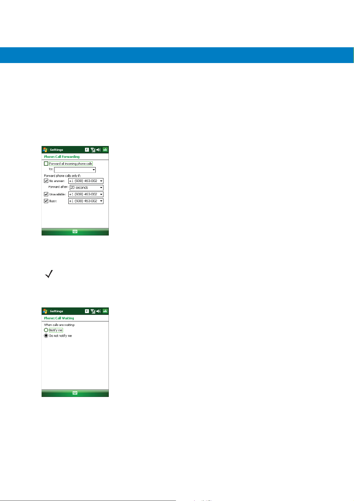
6 - 10 MC55 Integrator Guide
•
To forward incoming calls to a different phone number based on a specific situation, select one or more of the
check boxes under Forward phone calls only if:.
• No answer: enter the phone number to receive forwarded calls only when the phone cannot be
answered. Then select a time period from the Forward after: drop-down list. Options are 5, 10, 15, 20,
25, and 30 seconds.
• Unavailable: enter the phone number to receive forwarded calls only when the phone is turned off or the
user is unreachable.
• Busy: enter the phone number to receive forwarded calls only when the line is busy.
Figure 6-13
Call Forwarding
Call Waiting
NOTE Call Waiting may not be available on all networks. Check with your service provider for availability.
Call waiting notifies you of an incoming call when the phone is in a phone session. Select the Notify me radio
button to enable call waiting. Select the Do not notify me radio button to disable call waiting.
Figure 6-14
Call Waiting
Voice Mail and Text Messages
To use voice mail and send short messages, enter the voice mail and/or text message phone number in the
appropriate text boxes.
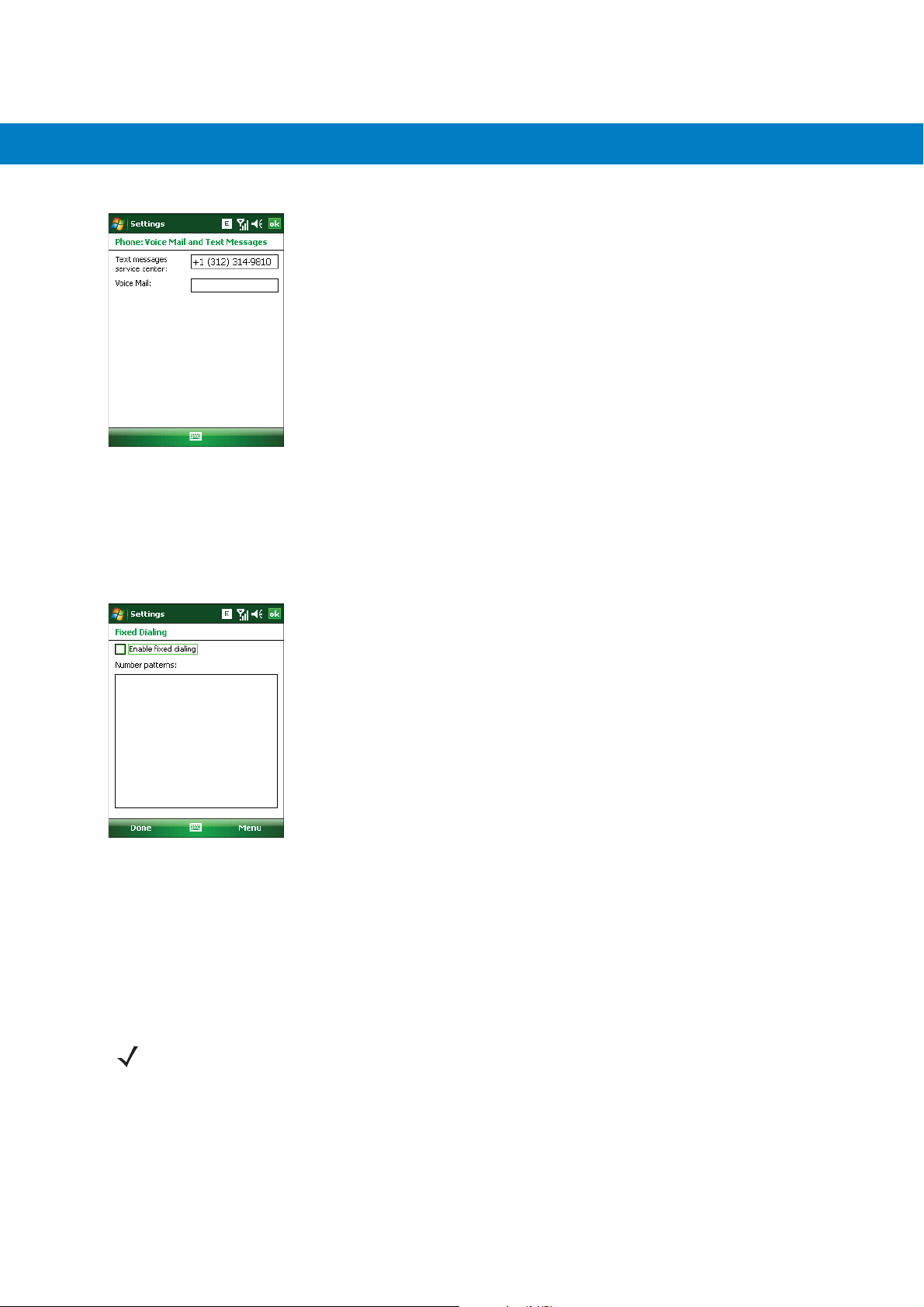
MC5574 - GSM Configuration 6 - 11
Figure 6-15
Voice Mail and Text Messages
Fixed Dialing
Use Fixed Dialing to restrict the phone to dial only the phone number(s) or area code(s) specified in a Fixed Dialing
list.
1. Select Fixed Dialing and tap Get Settings.
Figure 6-16
2. Select the Enable fixed dialing check box.
Fixed Dialing Window
3. To add a number to the list, tap Menu > Add.
4. Enter the phone number or area code to restrict and tap Done.
5. Repeat steps 3 and 4 to add more numbers, and tap Done twice when complete.
6. Enter PIN2 and tap Done.
NOTE PIN2 is buffered in the MC55 for seven minutes after entry and will not be requested again during this
period. Should entry of PIN2 be required then the user must either wait for seven minutes to expire or
alternatively perform a warm boot of the MC55.

6 - 12 MC55 Integrator Guide
Network
Use the Network tab to view available networks, determine the order in which the phone accesses another
network if the current network is unavailable, and specify whether to change networks manually or automatically.
The current network remains active until it’s changed, the signal is lost, or the SIM card is changed.
The network the MC55 currently uses appears in the Current network: field at the top of the window.
Changing Networks Manually
1. Ta p Start > Settings > Personal tab > Phone icon > Network tab
or
Start > Phone > Menu > Options > Network tab.
Figure 6-17
2. From the Network selection drop-down list, select Manual.
Figure 6-18
3. From the Choose Network window, select the network to use.
4. Ta p OK.
MC55 Phone Window - Network Tab
Choose Network
Viewing Available Networks
To view all wireless networks available:
1. Ta p Start > Settings > Personal tab > Phone icon > Network tab.
or
Start > Phone > Options > Network tab.

MC5574 - GSM Configuration 6 - 13
Figure 6-19
2. Ta p Find Network.
Figure 6-20
3. From the Choose Network window, select the network to use.
4. Ta p OK.
MC55 Phone Window - Network Tab
Choose Network
Setting Preferred Networks
Set networks in a preferred order of access. Setting preferred networks allows the MC55 to access a second
preferred network if the first is unavailable.
1. Ta p Start > Settings > Personal tab > Phone icon > Network tab
or
Start > Phone > Menu > Options > Network tab.
Figure 6-21
MC55 Phone Window - Network Tab

6 - 14 MC55 Integrator Guide
2. Ta p Set Networks to view all available networks.
Figure 6-22
3. Select the preferred networks by tapping one or more check boxes.
4. Ta p Move Up and Move Down, as necessary, to place the selected networks in the preferred order.
5. Ta p ok to send the new settings to the network.
6. From the Network tab, select Automatic from the Network selection drop-down list.
7. Ta p ok to exit settings.
Preferred Networks
Phone Info
Use the Phone Info tab to view hardware and software information about the phone.
1. Ta p Start > Settings > Personal tab > Phone icon > Phone Info tab
or
Start > Phone > Menu > Options > Phone Info tab.
Figure 6-23
2. Ta p ok to exit settings.
MC55 Phone Window - Phone Info Tab

Network Time Synchronization
The MC55 can be configured to synchronize the clock with the time from the carrier network. A registry key on the
MC55 has to be created to enable this feature.
Using a registry editor, navigate to the following:
[HKEY_LOCAL_MACHINE\SOFTWARE\Symbol\RIL\RHA\MC75]
Create the following key:
“SyncSystemTime”=dword:00000001
where:
dword:0 = disabled
dword:1 = enabled
After setting the registry key, warm boot the MC55.
Enhanced Operator Name String
MC5574 - GSM Configuration 6 - 15
The MC55 is enabled to download and display the name of the GSM network currently logged in to. Four registry
keys on the MC55 have to be edited to disable this feature.
Using a registry editor, navigate to each of the following:
[HKEY_LOCAL_MACHINE\Software\Microsoft\RIL]
[HKEY_LOCAL_MACHINE\Software\Microsoft\RIL\Configurations\GSM_HC25]
[HKEY_LOCAL_MACHINE\Comm\Cellular\Ril]
[HKEY_LOCAL_MACHINE\Comm\Cellular\Ril\Configurations\GSM_HC25]
Edit the following key:
“EonsEnable”=dword:1
where:
dword:0 = disabled
dword:1 = enabled (default)
After setting the registry key, warm boot the MC55.
Service Provider Name Display
The reg key (“UseServiceProviderName”) originally was used to fix the dual-line SIM card issue with value 2. But
for the Italian Post, the value 1 should be used to show the virtual carrier name (Poste Mobile).
[HKEY_LOCAL_MACHINE\Software\Microsoft\RIL]
“UseServiceProviderName”=dword:1

6 - 16 MC55 Integrator Guide
where:
dword:0 = Display provider name
dword:1 - Display service provider name (default)
dword:2 - Display both provider and service provider name
SMS Cell Broadcast
The MC55 can be configured to receive SMS Cell Broadcast messages from the carrier network. Registry keys on
the MC55 have to be modified to enable and control this feature.
Using a registry editor, navigate to the following:
[HKEY_LOCAL_MACHINE\Software\Microsoft\RIL\Configurations\GSM_MC75]
Create the following keys:
“EnableCBM”=dword:0
where:
0 = disabled (default)
1 = enabled
“EnableCBMChannels”=”0-65535”
where:
0-65535 = Channel Identifier
“EnableCBMDCS”=”0-255”
where:
0-255 = Message Handling, Coding Scheme and Language settings
After setting the registry key, warm boot the MC55.

Chapter 7 Maintenance & Troubleshooting
Introduction
This chapter includes instructions on cleaning and storing the MC55, and provides troubleshooting solutions for
potential problems during MC55 operation.
Maintaining the MC55
For trouble-free service, observe the following tips when using the MC55:
•
Do not scratch the screen of the MC55. When working with the MC55, use the supplied stylus or
plastic-tipped pens intended for use with a touch-sensitive screen. Never use an actual pen or pencil or other
sharp object on the surface of the MC55 screen.
Motorola recommends using a screen protector, p/n KT-67525-01R.
•
The touch-sensitive screen of the MC55 is glass. Do not to drop the MC55 or subject it to strong impact.
•
Protect the MC55 from temperature extremes. Do not leave it on the dashboard of a car on a hot day, and
keep it away from heat sources.
•
Do not store or use the MC55 in any location that is dusty, damp, or wet.
•
Use a soft lens cloth to clean the MC55. If the surface of the MC55 screen becomes soiled, clean it with a soft
cloth moistened with a diluted window-cleaning solution.
•
Periodically replace the rechargeable battery to ensure maximum battery life and product performance.
Battery life depends on individual usage patterns.

7 - 2 MC55 Integrator Guide
•
A screen protector is applied to the MC55. Motorola recommends using this to minimize wear and tear.
Screen protectors enhance the usability and durability of touch screen displays. Benefits include:
• Protection from scratches and gouges
• Durable writing and touch surface with tactile feel
• Abrasion and chemical resistance
• Glare reduction
• Keeping the device’s screen looking new
• Quick and easy installation.
Battery Safety Guidelines
•
The area in which the units are charged should be clear of debris and combustible materials or chemicals.
Particular care should be taken where the device is charged in a non commercial environment.
•
Follow battery usage, storage, and charging guidelines found in the user's guide.
•
Improper battery use may result in a fire, explosion, or other hazard.
•
To charge the mobile device battery, the battery and charger temperatures must be between +32 ºF and
+104 ºF (0 ºC and +40 ºC)
•
Do not use incompatible batteries and chargers. Use of an incompatible battery or charger may present a risk
of fire, explosion, leakage, or other hazard. If you have any questions about the compatibility of a battery or a
charger, contact Motorola Enterprise Mobility support.
•
To enable authentication of an approved battery, as required by IEEE1725 clause 10.2.1, all batteries will
carry a Motorola hologram. Do not fit any battery without checking it has the Motorola authentication
hologram.
•
Do not disassemble or open, crush, bend or deform, puncture, or shred.
•
Severe impact from dropping any battery-operated device on a hard surface could cause the battery to
overheat.
•
Do not short circuit a battery or allow metallic or conductive objects to contact the battery terminals.
•
Do not modify or remanufacture, attempt to insert foreign objects into the battery, immerse or expose to water
or other liquids, or expose to fire, explosion, or other hazard.
•
Do not leave or store the equipment in or near areas that might get very hot, such as in a parked vehicle or
near a radiator or other heat source. Do not place battery into a microwave oven or dryer.
•
Battery usage by children should be supervised.
•
Please follow local regulations to properly dispose of used re-chargeable batteries.
•
Do not dispose of batteries in fire.
•
In the event of a battery leak, do not allow the liquid to come in contact with the skin or eyes. If contact has
been made, wash the affected area with large amounts of water and seek medical advice.
•
If you suspect damage to your equipment or battery, contact Motorola Enterprise Mobility support to arrange
for inspection.

Cleaning
CAUTION Always wear eye protection.
WARNING! Avoid exposing this product to contact with hot oil or other flammable liquids. If such exposure
Materials Required
•
Alcohol wipes
•
Lens tissue
•
Cotton tipped applicators
•
Isopropyl alcohol
Maintenance & Troubleshooting 7 - 3
Read warning label on compressed air and alcohol product before using.
If you have to use any other solution for medical reasons please contact Motorola for more information.
occurs, unplug the device and clean the product immediately in accordance with these guidelines.
•
Can of compressed air with a tube.
Cleaning the MC55
Housing
Using the alcohol wipes, wipe the housing including keys and in-between keys.
Display
The display can be wiped down with the alcohol wipes, but care should be taken not to allow any pooling of liquid
around the edges of the display. Immediately dry the display with a soft, non-abrasive cloth to prevent streaking.
Scanner Exit Window
Wipe the scanner exit window periodically with a lens tissue or other material suitable for cleaning optical material
such as eyeglasses.
Connector
1. Remove the main battery from mobile computer.
2. Dip the cotton portion of the cotton tipped applicator in isopropyl alcohol.
3. Rub the cotton portion of the cotton tipped applicator back-and-forth across the connector on the bottom of the
MC55. Do not leave any cotton residue on the connector.
4. Repeat at least three times.
5. Use the cotton tipped applicator dipped in alcohol to remove any grease and dirt near the connector area.
6. Use a dry cotton tipped applicator and repeat steps 4 through 6.

7 - 4 MC55 Integrator Guide
7. Spray compressed air on the connector area by pointing the tube/nozzle about ½ inch away from the surface.
CAUTION: Do not point nozzle at yourself and others, ensure the nozzle or tube is away from your face.
8. Inspect the area for any grease or dirt, repeat if required.
Cleaning Cradle Connectors
To clean the connectors on a cradle:
1. Remove the DC power cable from the cradle.
2. Dip the cotton portion of the cotton tipped applicator in isopropyl alcohol.
3. Rub the cotton portion of the cotton tipped applicator along the pins of the connector. Slowly move the
applicator back-and-forth from one side of the connector to the other. Do not let any cotton residue on the
connector.
4. All sides of the connector should also be rubbed with the cotton tipped applicator.
5. Spray compressed air in the connector area by pointing the tube/nozzle about ½ inch away from the surface.
CAUTION: do not point nozzle at yourself and others, ensure the nozzle or tube is pointed away from your
face.
6. Ensure that there is no lint left by the cotton tipped applicator, remove lint if found.
7. If grease and other dirt can be found on other areas of the cradle, use lint free cloth and alcohol to remove.
8. Allow at least 10 to 30 minutes (depending on ambient temperature and humidity) for the alcohol to air dry
before applying power to cradle.
If the temperature is low and humidity is high, longer drying time is required. Warm temperature and dry
humidity requires less drying time.
Cleaning Frequency
The cleaning frequency is up to the customer’s discretion due to the varied environments in which the mobile
devices are used. They may be cleaned as frequently as required. However when used in dirty environments it
may be advisable to periodically clean the scanner exit window to ensure optimum scanning performance.
Troubleshooting
MC55
Table 7-1
Troubleshooting the MC55
Problem Cause Solution
MC55 does not turn
on.
Lithium-ion battery
not charged.
Lithium-ion battery
not installed
properly.
System crash. Perform a warm boot. If the MC55 still does not turn on, perform
Charge or replace the lithium-ion battery in the MC55.
Ensure battery is installed properly. See Installing the Battery on
page 1-4.
a cold boot. See Resetting the MC55 on page 1-6.

Maintenance & Troubleshooting 7 - 5
Table 7-1
Rechargeable
lithium-ion battery did
not charge.
Cannot see characters
on display.
During data
communication, no
data transmitted, or
transmitted data was
incomplete.
Troubleshooting the MC55 (Continued)
Problem Cause Solution
Battery failed. Replace battery. If the MC55 still does not operate, perform a
warm boot, then a cold boot. See Resetting the MC55 on page
1-6.
MC55 removed from
cradle while battery
was charging.
Extreme battery
temperature.
MC55 not powered
on.
MC55 removed from
cradle or
disconnected from
host computer
during
communication.
Incorrect cable
configuration.
Communication
software was
incorrectly installed
or configured.
Insert MC55 in cradle. The 2400 mAh battery fully charges in
approximately four hours and the 3600 mAh battery charges in
approximately six hours.
Battery does not charge if ambient temperature is below 0°C
(32°F) or above 40°C (104°F).
Press the Power button.
Replace the MC55 in the cradle, or reattach the communication
cable and re-transmit.
See the system administrator.
Perform setup. See Chapter 2, Accessories for details.
No sound. Volume setting is low
or turned off.
MC55 shuts off. MC55 is inactive. The MC55 turns off after a period of inactivity. If the MC55 is
Battery is not
inserted properly.
Battery is depleted. Replace the battery.
Tapping the window
buttons or icons does
not activate the
corresponding feature.
Screen is not
calibrated correctly.
The system is not
responding.
Adjust the volume. Adjust the volume. Refer to the MC55 User
Guide.
running on battery power, set this period from 1 to 5 minutes, in
one-minute intervals. If the MC55 is running on external power,
set this period to 1, 2, 5, 10, 15, or 30 minutes.
Check the Power window by selecting Start > Settings >
System tab and tapping the Power icon. Select the Advanced
tab and change the setting for a longer delay before the
automatic shutoff feature activates.
Insert the battery properly. See Installing the Battery on page 1-4.
Re-calibrate the screen. Press Blue key - Backspace key or tap
Start > Settings > System tab > Screen icon > Align Screen
button.
Warm boot the system. See Resetting the MC55 on page 1-6.

7 - 6 MC55 Integrator Guide
Table 7-1
A message appears
stating that the MC55
memory is full.
The Charging/Battery
Status LED flashes
with the Power button
is pressed and the
MC55 does not turn
on.
Camera application
does not launch.
The MC55 does not
decode with reading
bar code.
Troubleshooting the MC55 (Continued)
Problem Cause Solution
Too many files
stored on the MC55.
Too many
applications i nstalled
on the MC55.
The MC55’s battery
is low.
DataWedge
application running.
Scanning applicati on
is not loaded.
Unreadable bar
code.
Delete unused memos and records. If necessary, save these
records on the host computer (or use an SD card for additional
memory).
Remove user-installed applications on the MC55 to recover
memory. Select Start > Settings > System tab and tap the
Remove Programs icon. Select the unused program and tap
Remove.
Recharge the battery.
Stop DataWedge application. Tap Start > Settings > System >
Task Manager. Select DataWedge application and tap End
Task.
Load a scanning application on the MC55. See the system
administrator.
Ensure the symbol is not defaced.
Cannot connect to
service provider.
Distance between
exit window and bar
code is incorrect.
MC55 is not
programmed for the
bar code.
MC55 is not
programmed to
generate a beep.
Battery is low. If the scanner stops emitting a laser beam upon a trigger press,
SIM not installed
properly.
Place the MC55 within proper scanning range.
Program the MC55 to accept the type of bar code being scanned.
Refer to the EMDK or Control Panel application.
If the MC55 does not beep on a good decode, set the application
to generate a beep on good decode.
check the battery level. When the battery is low, the scanner
shuts off before the MC55 low battery condition notification.
Note: If the scanner is still not reading symbols, contact the
distributor or Motorola.
Re-install SIM card.

Bluetooth Connection
Maintenance & Troubleshooting 7 - 7
Table 7-2
MC55 cannot find
any Bluetooth
devices nearby.
There is a delay in
the Bluetooth stack
re-initializing during
a resume from
suspend.
Troubleshooting Bluetooth Connection
Problem Cause Solution
Single Slot USB Cradle
Table 7-3
LEDs do not light
when MC55 or
spare battery is
inserted.
Troubleshooting the Single Slot USB Cradle
Symptom Possible Cause Action
Cradle is not receiving
power.
MC55 is not seated
firmly in the cradle.
Too far from other
Bluetooth devices.
The Bluetooth device(s)
nearby are not turned on.
The Bluetooth device(s)
are not in discoverable
mode.
This is normal behavior. No solution required.
Move closer to the other Bluetooth device(s), within a range
of 10 meters.
Turn on the Bluetooth device(s) to find.
Set the Bluetooth device(s) to discoverable mode. If needed,
refer to the device’s user documentation for help.
Ensure the power cable is connected securely to both the
cradle and to AC power.
Remove and re-insert the MC55 into the cradle, ensuring it
is firmly seated.
MC55 battery is not
charging.
Spare battery is not
seated firmly in the
cradle.
MC55 was removed
from cradle or cradle
was unplugged from AC
power too soon.
Battery is faulty. Verify that other batteries charge properly. If so, replace the
The MC55 is not fully
seated in the cradle.
Ambient temperature of
the cradle is too warm.
Remove and re-insert the spare battery into the charging
slot, ensuring it is firmly seated.
Ensure cradle is receiving power. Ensure MC55 is seated
correctly. Confirm main battery is charging under Start >
Settings > System > Power. The 2400 mAh battery fully
charges in approximately four hours and the 3600 mAh
battery charges in approximately six hours.
faulty battery.
Remove and re-insert the MC55 into the cradle, ensuring it
is firmly seated.
Move the cradle to an area where the ambient temperature
is between 0
o
C and 35oC.

7 - 8 MC55 Integrator Guide
Table 7-3
Spare battery is not
charging.
During data
communication, no
data transmits, or
transmitted data
was incomplete.
Troubleshooting the Single Slot USB Cradle (Continued)
Symptom Possible Cause Action
Battery not fully seated
in charging slot.
Battery inserted
incorrectly.
Battery is faulty. Verify that other batteries charge properly. If so, replace the
MC55 removed from
cradle during
communication.
Communication
software is not installed
or configured properly.
Four Slot Ethernet Cradle
Table 7-4
Troubleshooting the Four Slot Ethernet Cradle
Symptom Cause Solution
Remove and re-insert the spare battery in the cradle,
ensuring it is firmly seated.
Re-insert the battery so the charging contacts on the battery
align with the contacts on the cradle.
faulty battery.
Replace MC55 in cradle and retransmit.
Perform setup as described in Chapter 3, ActiveSync.
Battery is not
charging.
Battery was removed
from the charger or
charger was unplugged
from AC power too soon.
Battery is faulty. Verify that other batteries charge properly. If so, replace the
MC55 is not inserted
correctly in the cradle.
Ambient temperature of
the cradle is too warm.
Replace the MC55 in the cradle. The 2400 mAh battery fully
charges in approximately four hours and the 3600 mAh
battery charges in approximately six hours. Tap Start >
Settings > System > Power to view battery status.
faulty battery.
Remove the MC55 and reinsert it correctly. Verify charging is
active. Tap Start > Settings > System > Power to view
battery status.
Move the cradle to an area where the ambient temperature is
between 0
o
C and 35oC.

Maintenance & Troubleshooting 7 - 9
Table 7-4
Attempt by the MC55
to ActiveSync failed.
Troubleshooting the Four Slot Ethernet Cradle (Continued)
Symptom Cause Solution
MC55 removed from the
cradle while the LED was
blinking green.
Using an outdated
version of ActiveSync.
ActiveSync on the host
computer has not yet
closed the previous
ActiveSync session.
Incorrect cable
configuration.
Communication so ftware
improperly configured.
MC55 ActiveSync
disabled or not
configured to accept
network connection.
Host ActiveSync
disabled or not
configured to accept
network connection.
Wait one minute and reinsert the MC55 in the cradle. This
allows the cradle to attempt another synchronization.
Visit http://www.microsoft.com for the latest ActiveSync
software.
Wait one minute and reinsert the MC55 in the cradle. This
allows the cradle to attempt another synchronization.
Ensure the correct cable (Ethernet) is used with the cradle.
Perform setup as described in Chapter 3, ActiveSync.
On the MC55, tap Start > ActiveSync > Tools > Options >
Options button. Then, uncheck the Enable PC sync using
this connection: check box.
On the host computer, check File > Connection Settings >
Allow network (Ethernet) Server Connection with this
desktop computer.
During
communication, no
data was transmitted,
or transmitted data
was incomplete.
Vehicle Cradle
Table 7-5
MC55 battery
charging LED does
not light up.
Troubleshooting the Vehicle Cradle
Symptom Possible Cause Action
MC55 removed from
cradle during
communication.
MC55 has no active
connection.
Cradle is not receiving
power.
Replace MC55 in cradle and retransmit.
An icon is visible in the status bar if a connection is active.
Ensure the power input cable is securely connected to the
cradle’s power port.

7 - 10 MC55 Integrator Guide
Table 7-5
MC55 battery is not
recharging.
Troubleshooting the Vehicle Cradle
Symptom Possible Cause Action
MC55 was removed from
the cradle too soon.
Battery is faulty. Replace the battery.
MC55 is not placed
correctly in the cradle.
Ambient temperature of
the cradle is too warm.
Four Slot Spare Battery Charger
Table 7-6
Battery not charging. Battery was removed
Troubleshooting the Four Slot Spare Battery Charger
Symptom Possible Cause Action
from the charger or
charger was unplugged
from AC power too soon.
Replace the MC55 in the cradle. The 2400 mAh battery fully
charges in approximately four hours and the 3600 mAh
battery charges in approximately six hours.
Remove the MC55 from the cradle, and re-insert correctly. If
the battery still does not charge, contact customer support.
The MC55 battery charging LED slowly blinks amber when
the MC55 is correctly inserted and charging.
Move to an area where the ambient temperature is between
o
0
C and 35oC.
Re-insert the battery in the charger or re-connect the charger’s
power supply. The 2400 mAh battery fully charges in
approximately four hours and the 3600 mAh battery charges in
approximately six hours.
Cables
Table 7-7
Symptom Possible Cause Action
MC55 battery is
not charging.
Battery is faulty. Verify that other batteries charge properly. If so, replace the
Battery contacts not
connected to charger.
Troubleshooting the Cables
MC55 was
disconnected from AC
power too soon.
Battery is faulty. Verify that other batteries charge properly. If so, replace the faulty
The MC55 is not fully
attached to power.
faulty battery.
Verify that the battery is seated in the battery well correctly with
the contacts facing down.
Connect the power cable correctly. Confirm main battery is charging
under Start > Settings > System > Power. The 2400 mAh battery
fully charges in approximately four hours and the 3600 mAh battery
charges in approximately six hours.
battery.
Detach and re-attach the power cable to the MC55, ensuring it is
firmly connected.
 Loading...