

Page 1
DS6708 Digital Scanner
Product Reference Guide
Page 2

Page 3

DS6708 Digital Scanner
Product Reference Guide
72E-86039-01
Revision A
October 2006
Page 4

DS6708 Digital Scanner Product Reference Guide
© 2006 by Symbol Technologies, Inc. All rights reserved.
No part of this publication may be reproduced or used in any form, or by any electrical or mechanical means,
without permission in writing from Symbol. This includes electronic or mechanical means, such as
photocopying, recording, or information storage and retrieval systems. The material in this manual is subject to
change without notice.
The software is provided strictly on an “as i s” basis. All sof twar e, including firmware, furnished to the user is on
a licensed basis. Symbol grants to the user a non-tran sferable an d non-exclusive license to use each sof tware
or firmware program delivered hereunder (licensed program) . Except as n oted below, such license may not be
assigned, sublicensed, or otherwise transferred by th e user without pr ior written consent of Symbo l. No right to
copy a licensed program in whole or in part is granted, exce pt as permitted unde r copyright law. The user shall
not modify , merge, or incorporate any for m or portion of a licensed program with other pro gram material, create
a derivative work from a licensed program , or us e a li censed program in a network without written permission
from Symbol. The user agrees to maintain Symbol’s copyright notice on the licensed programs delivered
hereunder , and to include the same on any authorized copies it makes, in whole or in part. The user agrees not
to decompile, disassemble, decode, or reverse engineer any licensed program delivered to the user or any
portion thereof.
Symbol reserves the right to make changes to any software or product to improve reliability , function, or design.
Symbol does not assume any product liability arising out of, or in connection with, the application or use of any
product, circuit, or application described herein.
No license is granted, either expressly or by implication, estoppel, or otherwise under any Symbol
Technologies, Inc., intellectual property rights. An implied license only exists for equipment, circuits, and
subsystems contained in Symbol products.
Symbol, Spectrum One, and Spectrum24 are registered trademarks of Symbol Technologies, Inc. Bluetooth is
a registered trademark of Bluetooth SIG. Microsoft, Windows and ActiveSync are either registered trademarks
or trademarks of Microsoft Corporation. Other product n ame s me ntioned in this man ual ma y be tr adema rks or
registered trademarks of their respective companies and are hereby acknowledge d.
Symbol Technologies, Inc.
One Symbol Plaza
Holtsville, New York 11742-1300
http://www.symbol.com
Page 5

Revision History
Changes to the original manual are listed below:
Change Date Description
-01 Rev A 10/2006 Initial Release.
Page 6

DS6708 Digital Scanner Product Reference Guide
Page 7

Table of Contents
Revision History............................................................................................................. iii
About This Guide
Introduction ................................................................................................................... xi
Configurations............................................................................................................... xi
Chapter Descriptions..................................................................................................... xi
Notational Conventions................................................................................................. xii
Related Documents....................................................................................................... xiii
Service Information....................................................................................................... xiii
Symbol Global Interaction Center........................................................................... xiv
Chapter 1: Getting Started
Introduction .................................................................................................................. 1-1
Supported Interfaces .................................................................................................... 1-2
Unpacking .................................................................................................................... 1-2
Setting Up the Digital Scanner ..................................................................................... 1-3
Installing the Interface Cable .................................................................................. 1-3
Removing the Interface Cable ................................................................................ 1-3
Connecting a Synapse Cable Interface (DS6708 0nly) .......................................... 1-4
Connecting Power (if required) .............................................................................. 1-4
Configuring the Digital Scanner ............................................................................. 1-4
Mounting the Digital Scanner ....................................................................................... 1-5
Desk Mount ............................................................................................................ 1-5
Wall Mount ............................................................................................................. 1-5
Chapter 2: Scanning
Introduction .................................................................................................................. 2-1
Beeper Definitions ........................................................................................................ 2-2
LED Definitions ............................................................................................................ 2-4
Scanning in Hand-Held Mode ...................................................................................... 2-4
Scanning with the Digital Scanner ......................................................................... 2-4
Aiming ................................................................................................................... 2-5
Scanning in Hands-Free Mode .................................................................................... 2-6
Decode Zones .............................................................................................................. 2-7
Page 8

ii DS6708 Digital Scanner Product Reference Guide
Chapter 3: Maintenance & Technical Specifications
Introduction ................................................................................................................... 3-1
Maintenance ................................................................................................................. 3-1
Troubleshooting ............................................................................................................ 3-2
Technical Specifications ............................................................................................... 3-4
Digital Scanner Signal Descriptions .............................................................................. 3-6
Chapter 4: User Preferences & Miscellaneous Digital Scanner Options
Introduction ................................................................................................................... 4-1
Scanning Sequence Examples ..................................................................................... 4-2
Errors While Scanning .................................................................................................. 4-2
User Preferences/Miscellaneous Options Parameter Defaults ..................................... 4-2
User Preferences .......................................................................................................... 4-4
Set Default Parameter ............................................................................................. 4-4
Parameter Scanning ............................................................................................... 4-4
Beeper Tone ........................................................................................................... 4-5
Beeper Volume ....................................................................................................... 4-6
Power Mode ............................................................................................................ 4-6
Time Delay to Low Power Mode ............................................................................. 4-7
Trigger Mode ........................................................................................................... 4-8
Picklist Mode ........................................................................................................... 4-9
Decode Session Timeout ........................................................................................ 4-10
Timeout Between Decodes, Same Symbol ............................................................. 4-10
Beep After Good Decode ........................................................................................ 4-11
Miscellaneous Scanner Parameters ............................................................................. 4-12
Transmit Code ID Character ................................................................................... 4-12
Prefix/Suffix Values ................................................................................................. 4-13
Scan Data Transmission Format ............................................................................. 4-14
FN1 Substitution Values .......................................................................................... 4-15
Transmit “No Read” Message ................................................................................. 4-16
Synapse Interface ................................................................................................... 4-16
Chapter 5: Decoding Preferences
Introduction ................................................................................................................... 5-1
Scanning Sequence Examples ..................................................................................... 5-1
Errors While Scanning .................................................................................................. 5-2
Decoding Preferences Parameter Defaults .................................................................. 5-2
Decoding Preferences .................................................................................................. 5-3
Decoding Illumination .............................................................................................. 5-3
Illumination Bank Control ........................................................................................ 5-4
Decode Aiming Pattern ........................................................................................... 5-5
Page 9

Table of Contents iii
Chapter 6: USB Interface
Introduction .................................................................................................................. 6-1
Connecting a USB Interface ......................................................................................... 6-2
USB Parameter Defaults .............................................................................................. 6-3
USB Host Parameters .................................................................................................. 6-4
USB Device Type ................................................................................................... 6-4
USB Country Keyboard Types - Country Codes .................................................... 6-5
USB Keystroke Delay ............................................................................................. 6-7
USB CAPS Lock Override ...................................................................................... 6-7
USB Ignore Unknown Characters .......................................................................... 6-8
Emulate Keypad ..................................................................................................... 6-8
Emulate Keypad with Leading Zero ....................................................................... 6-9
USB Keyboard FN 1 Substitution ........................................................................... 6-9
Function Key Mapping ........................................................................................... 6-10
Simulated Caps Lock ............................................................................................. 6-10
Convert Case ......................................................................................................... 6-11
ASCII Character Set for USB ....................................................................................... 6-12
Chapter 7: RS-232 Interface
Introduction .................................................................................................................. 7-1
Connecting an RS-232 Interface .................................................................................. 7-2
RS-232 Parameter Defaults ......................................................................................... 7-3
RS-232 Host Parameters ............................................................................................. 7-4
RS-232 Host Types ................................................................................................ 7-6
Baud Rate .............................................................................................................. 7-7
Parity ...................................................................................................................... 7-9
Stop Bit Select ........................................................................................................ 7-10
Data Bits ................................................................................................................. 7-10
Check Receive Errors ............................................................................................ 7-11
Hardware Handshaking .......................................................................................... 7-11
Software Handshaking ........................................................................................... 7-13
Host Serial Response Time-out ............................................................................. 7-15
RTS Line State ....................................................................................................... 7-16
Beep on <BEL> ...................................................................................................... 7-16
Intercharacter Delay ............................................................................................... 7-17
Nixdorf Beep/LED Options ..................................................................................... 7-18
Ignore Unknown Characters .................................................................................. 7-18
ASCII Character Set for RS-232 .................................................................................. 7-19
Chapter 8: IBM 468X / 469X Interface
Introduction .................................................................................................................. 8-1
Connecting to an IBM 468X/469X Host ....................................................................... 8-2
IBM Parameter Defaults ............................................................................................... 8-3
IBM 468X/469X Host Parameters ................................................................................ 8-4
Port Address .......................................................................................................... 8-4
Convert Unknown to Code 39 ................................................................................ 8-5
Page 10

iv DS6708 Digital Scanner Product Reference Guide
Chapter 9: Wand Emulation Interface
Introduction ................................................................................................................... 9-1
Connecting Using Wand Emulation .............................................................................. 9-2
Wand Emulation Parameter Defaults ............................................................................ 9-3
Wand Emulation Host Parameters ................................................................................ 9-4
Wand Emulation Host Types ................................................................................... 9-4
Leading Margin (Quiet Zone) .................................................................................. 9-5
Polarity .................................................................................................................... 9-6
Ignore Unknown Characters ................................................................................... 9-6
Convert All Bar Codes to Code 39 .......................................................................... 9-7
Convert Code 39 to Full ASCII ............................................................................... 9-8
Chapter 10: Keyboard Wedge Interface
Introduction ................................................................................................................... 10-1
Connecting a Keyboard Wedge Interface ..................................................................... 10-2
Keyboard Wedge Parameter Defaults .......................................................................... 10-3
Keyboard Wedge Host Parameters .............................................................................. 10-4
Keyboard Wedge Host Types ................................................................................. 10-4
Keyboard Wedge Country Types - Country Codes ................................................. 10-5
Ignore Unknown Characters ................................................................................... 10-7
Keystroke Delay ...................................................................................................... 10-7
Intra-Keystroke Delay .............................................................................................. 10-8
Alternate Numeric Keypad Emulation ..................................................................... 10-8
Caps Lock On ......................................................................................................... 10-9
Caps Lock Override ................................................................................................ 10-9
Convert Wedge Data ............................................................................................... 10-10
Function Key Mapping ............................................................................................ 10-10
FN1 Substitution ...................................................................................................... 10-11
Send Make and Break ............................................................................................. 10-11
Keyboard Maps .................................................................... ........... .......... ........... ... 10-12
ASCII Character Set for Keyboard Wedge ................................................................... 10-14
Chapter 11: Scanner Emulation Interface
Introduction ................................................................................................................... 11-1
Connecting Using Scanner Emulation .......................................................................... 11-2
Scanner Emulation Parameter Defaults ........................................................................ 11-3
Scanner Emulation Host ............................................................................................... 11-4
Scanner Emulation Host Parameters ...................................................................... 11-4
Beep Style ......................................................................................................... 11-4
Parameter Pass-Through ........................................................................................ 11-5
Convert Newer Code Types .................................................................................... 11-5
Module Width .......................................................................................................... 11-6
Convert All Bar Codes to Code 39 .......................................................................... 11-7
Code 39 Full ASCII Conversion .............................................................................. 11-7
Transmission Timeout ............................................................................................. 11-8
Ignore Unknown Characters ................................................................................... 11-9
Leading Margin ....................................................................................................... 11-9
Check For Decode LED .......................................................................................... 11-10
Page 11

Table of Contents v
Chapter 12: 123Scan
Introduction .................................................................................................................. 12-1
123Scan Parameter ..................................................................................................... 12-2
Chapter 13: Symbologies
Introduction .................................................................................................................. 13-1
Scanning Sequence Examples .................................................................................... 13-1
Errors While Scanning ................................................................................................. 13-2
Symbology Parameter Defaults ................................................................................... 13-2
UPC/EAN ..................................................................................................................... 13-6
Enable/Disable UPC-A ........................................................................................... 13-6
Enable/Disable UPC-E ........................................................................................... 13-6
Enable/Disable UPC-E1 ......................................................................................... 13-7
Enable/Disable EAN-8/JAN-8 ................................................................................ 13-7
Enable/Disable EAN-13/JAN-13 ............................................................................ 13-8
Enable/Disable Bookland EAN ............................................................................... 13-8
Decode UPC/EAN/JAN Supplementals ................................................................. 13-9
UPC/EAN/JAN Supplemental Redundancy ........................................................... 13-10
Transmit UPC-A Check Digit .................................................................................. 13-11
Transmit UPC-E Check Digit .................................................................................. 13-11
Transmit UPC-E1 Check Digit ................................................................................ 13-12
UPC-A Preamble .................................................................................................... 13-13
UPC-E Preamble .................................................................................................... 13-14
UPC-E1 Preamble .................................................................................................. 13-15
Convert UPC-E to UPC-A ...................................................................................... 13-16
Convert UPC-E1 to UPC-A .................................................................................... 13-16
EAN-8/JAN-8 Extend ............................................................................................. 13-17
UCC Coupon Extended Code ................................................................................ 13-17
Code 128 ...................................................................................................................... 13-18
Enable/Disable Code 128 ...................................................................................... 13-18
Enable/Disable UCC/EAN-128 ............................................................................... 13-18
Enable/Disable ISBT 128 ....................................................................................... 13-19
Code 39 ........................................................................................................................ 13-19
Enable/Disable Code 39 ........................................................................................ 13-19
Enable/Disable Trioptic Code 39 ............................................................................ 13-20
Convert Code 39 to Code 32 ................................................................................. 13-20
Code 32 Prefix ....................................................................................................... 13-21
Set Lengths for Code 39 ........................................................................................ 13-21
Code 39 Check Digit Verification ........................................................................... 13-23
Transmit Code 39 Check Digit ............................................................................... 13-23
Code 39 Full ASCII Conversion ............................................................................. 13-24
Code 39 Buffering - Scan & Store .......................................................................... 13-24
Buffer Data ....................................................................................................... 13-25
Clear Transmission Buffer ................................................................................ 13-25
Transmit Buffer ................................................................................................. 13-26
Overfilling Transmission Buffer ........................................................................ 13-26
Attempt to Transmit an Empty Buffer ............................................................... 13-26
Code 93 ........................................................................................................................ 13-27
Page 12

vi DS6708 Digital Scanner Product Reference Guide
Enable/Disable Code 93 ......................................................................................... 13-27
Set Lengths for Code 93 ......................................................................................... 13-27
Code 11 ........................................................................................................................ 13-29
Code 11 ................................................................................................................... 13-29
Set Lengths for Code 11 ......................................................................................... 13-29
Code 11 Check Digit Verification ............................................................................ 13-31
Transmit Code 11 Check Digits .............................................................................. 13-31
Interleaved 2 of 5 (ITF) ................................................................................................. 13-32
Enable/Disable Interleaved 2 of 5 ........................................................................... 13-32
Set Lengths for Interleaved 2 of 5 ........................................................................... 13-32
I 2 of 5 Check Digit Verification ............................................................................... 13-34
Transmit I 2 of 5 Check Digit ................................................................................... 13-34
Convert I 2 of 5 to EAN-13 ...................................................................................... 13-35
Discrete 2 of 5 (DTF) .................................................................................................... 13-35
Enable/Disable Discrete 2 of 5 ................................................................................ 13-35
Set Lengths for Discrete 2 of 5 ................................................................................ 13-36
Codabar (NW - 7) .......................................................................................................... 13-38
Enable/Disable Codabar ......................................................................................... 13-38
Set Lengths for Codabar ......................................................................................... 13-38
CLSI Editing ............................................................................................................ 13-40
NOTIS Editing ......................................................................................................... 13-40
MSI ................................................................................................................................ 13-41
Enable/Disable MSI ................................................................................................. 13-41
Set Lengths for MSI ................................................................................................ 13-41
MSI Check Digits ..................................................................................................... 13-43
Transmit MSI Check Digit(s) ................................................................................... 13-43
MSI Check Digit Algorithm ...................................................................................... 13-44
Postal Codes ................................................................................................................. 13-44
US Postnet .............................................................................................................. 13-44
US Planet ................................................................................................................ 13-45
UK Postal ................................................................................................................ 13-45
Transmit UK Postal Check Digit .............................................................................. 13-46
Japan Postal ........................................................................................................... 13-46
Australian Postal ..................................................................................................... 13-47
Dutch Postal ............................................................................................................ 13-47
Transmit US Postal Check Digit .............................................................................. 13-48
RSS (Reduced Space Symbology) ............................................................................... 13-49
RSS-14 .................................................................................................................... 13-49
RSS Limited ............................................................................................................ 13-49
RSS Expanded ........................................................................................................ 13-50
Convert RSS to UPC/EAN ...................................................................................... 13-50
Composite ..................................................................................................................... 13-51
Composite CC-C ..................................................................................................... 13-51
Composite CC-A/B .................................................................................................. 13-51
Composite TLC-39 .................................................................................................. 13-52
UPC Composite Mode ............................................................................................ 13-52
Composite Beep Mode ............................................................................................ 13-53
UCC/EAN Code 128 Emulation Mode for UCC/EAN Composite Codes ................ 13-53
2D Symbologies ............................................................................................................ 13-54
Page 13

Table of Contents vii
Enable/Disable PDF417 ......................................................................................... 13-54
Enable/Disable MicroPDF417 ................................................................................ 13-54
Code 128 Emulation ............................................................................................... 13-55
Data Matrix ............................................................................................................. 13-56
Maxicode ................................................................................................................ 13-56
QR Code ................................................................................................................ 13-57
Redundancy Level ....................................................................................................... 13-57
Redundancy Level 1 .............................................................................................. 13-57
Redundancy Level 2 .............................................................................................. 13-58
Redundancy Level 3 .............................................................................................. 13-58
Redundancy Level 4 .............................................................................................. 13-58
Security Level ............................................................................................................... 13-60
Intercharacter Gap Size ......................................................................................... 13-61
Report Version ............................................................................................................. 13-61
Macro PDF Features .................................................................................................... 13-62
Flush Macro Buffer ................................................................................................. 13-62
Abort Macro PDF Entry .......................................................................................... 13-62
Chapter 14: Advanced Data Formatting
Introduction .................................................................................................................. 14-1
Rules: Criteria Linked to Actions .................................................................................. 14-1
Using ADF Bar Codes .................................................................................................. 14-2
ADF Bar Code Menu Example ..................................................................................... 14-2
Rule 1: The Code 128 Scanning Rule .................................................................... 14-3
Rule 2: The UPC Scanning Rule ............................................................................ 14-3
Alternate Rule Sets ................................................................................................ 14-3
Rules Hierarchy (in Bar Codes) ............................................................................. 14-4
Default Rules .......................................................................................................... 14-5
Special Commands ...................................................................................................... 14-5
Pause Duration ...................................................................................................... 14-5
Begin New Rule ..................................................................................................... 14-5
Save Rule ............................................................................................................... 14-6
Erase ...................................................................................................................... 14-6
Quit Entering Rules ................................................................................................ 14-6
Disable Rule Set .................................................................................................... 14-7
Criteria .......................................................................................................................... 14-8
Code Types ............................................................................................................ 14-8
Code Lengths ......................................................................................................... 14-14
Message Containing A Specific Data String .......................................................... 14-18
Specific String at Start ...................................................................................... 14-18
Specific String, Any Location ............................................................................ 14-19
Any Message OK ............................................................................................. 14-19
Numeric Keypad ............................................................................................... 14-20
Rule Belongs To Set ........................................................................................ 14-22
Actions ......................................................................................................................... 14-23
Send Data .............................................................................................................. 14-23
Setup Field(s) ......................................................................................................... 14-26
Move Cursor ..................................................................................................... 14-27
Page 14

viii DS6708 Digital Scanner Product Reference Guide
Send Pause ....................................................................................................... 14-27
Skip Ahead ........................................................................................................ 14-28
Skip Back ......................................................................................................... 14-29
Send Preset Value ............................................................................................ 14-31
Modify Data ............................................................................................................. 14-31
Remove All Spaces ........................................................................................... 14-31
Crunch All Spaces ............................................................................................. 14-31
Stop Space Removal ........................................................................................ 14-32
Remove Leading Zeros ..................................................................................... 14-32
Stop Zero Removal ........................................................................................... 14-32
Pad Data with Spaces ............................................................................................. 14-33
Pad Data with Zeros ................................................................................................ 14-37
Beeps ...................................................................................................................... 14-42
Send Keystroke (Control Characters and Keyboard Characters) ........................... 14-42
Control Characters ............................................................................................ 14-42
Keyboard Characters ........................................................................................ 14-47
Send ALT Characters ........................................................................................ 14-61
Send Keypad Characters .................................................................................. 14-66
Send Function Key ............................................................................................ 14-71
Send Right Control Key ........................................................................................... 14-78
Send Graphic User Interface (GUI) Characters ...................................................... 14-79
Turn On/Off Rule Sets ............................................................................................. 14-84
Alphanumeric Keyboard ................................................................................................ 14-86
Appendix A: Standard Default Parameters
Appendix B: Programming Reference
Symbol Code Identifiers ................................................................................................ B-1
AIM Code Identifiers ..................................................................................................... B-3
Appendix C: Sample Bar Codes
Code 39 ........................................................................................................................ C-1
UPC/EAN ...................................................................................................................... C-1
UPC-A, 100% .......................................................................................................... C-1
EAN-13, 100% ........................................................................................................ C-2
Code 128 ...................................................................................................................... C-2
Interleaved 2 of 5 .......................................................................................................... C-2
RSS 14 .......................................................................................................................... C-3
PDF417 ......................................................................................................................... C-3
Data Matrix .................................................................................................................... C-3
Maxicode ....................................................................................................................... C-4
QR Code ....................................................................................................................... C-4
US Postnet .................................................................................................................... C-4
UK Postal ...................................................................................................................... C-5
Page 15

Table of Contents ix
Appendix D: Numeric Bar Codes
Numeric Bar Codes ...................................................................................................... D-1
Cancel .......................................................................................................................... D-2
Appendix E: ASCII Character Sets
Glossary
Index
Page 16

x DS6708 Digital Scanner Product Reference Guide
Page 17

About This Guide
Introduction
The DS6708 Digital Scanner Product Reference Guide provides general instructions for setting up, operating,
maintaining and troubleshooting the DS6708 digital scanner.
NOTE The DS6708 premier digital decoder does not support imaging. For imaging features and
parameters, refer to the DS6707 Digital Imager Scanner Product Reference Guide,
p/n 72E-83978-xx.
Configurations
This guide covers all operating features of the DS6708 Standard Range digital scanner.
About This Guide
Chapter Descriptions
Topics covered in this guide are as follows:
•
Chapter 1, Getting Started provides a product overview, unpacking instructions, and cable connection
information.
•
Chapter 2, Scanning describes parts of the digital scanner, beeper and LED definitions, and how to use
the digital scanner in hand-held and hands-free mo de s.
•
Chapter 3, Maintenance & Technical Specifications provides information on how to care for the digital
scanner, troubleshooting, and technical specifications.
•
Chapter 4, User Preferences & Miscellaneous Digital Scanner Options provides commonly used bar
codes to customize how data is transmitted to the host device and programming bar codes for selecting
user preference features for the digital scanner.
•
Chapter 5, Decoding Preferences provides decoding preference features and the programming bar
codes for selecting these features.
•
Chapter 6, USB Interface describes how to set up the digital scanner with a USB host.
•
Chapter 7, RS-232 Interface describes how to set up the digital scanner with an RS-232 host, such as
point-of-sale devices, host computers, or other devices with an available RS-232 port.
•
Chapter 8, IBM 468X / 469X Interface describes how to set up the digital scanner with IBM 468X/469X
POS systems.
Page 18

xii DS6708 Digital Scanner Product Reference Guide
•
Chapter 9, Wand Emulation Interface describes how to set up the digital scanner with a Wand Emulation
host when Wand Emulation communication is needed.
•
Chapter 10, Keyboard Wedge Interface describes how to set up a Keyboard Wedge interface with the
digital scanner.
•
Chapter 11, Scanner Emulation Interface describes how to set up the digital scanne r with an Undecoded
Scanner Emulation host.
•
Chapter 12, 123Scan describes the 123Scan PC-based scanner configura tion tool, and provides the bar
code to scan to communicate with the 123Scan program.
•
Chapter 13, Symbologies describes all symbology features and provides the programming bar codes
necessary for selecting these features for the digital scanne r.
•
Chapter 14, Advanced Data Formatting (ADF) describes how to customize scanned data before
transmitting to the host.
•
Appendix A, Standard Defaul t Parameters provides a table of all host devices and miscellaneous
scanner defaults.
•
Appendix B, Programming Reference provides a table of AIM code identifiers, ASCII character
conversions, and keyboard maps.
•
Appendix C, Sample Bar Codes includes sample bar codes.
•
Appendix D, Numeric Bar Codes includes the numeric bar codes to scan for parameters requiring
specific numeric values.
•
Appendix E, ASCII Character Sets provides ASCII character value tables.
Notational Conventions
The following conventions are used in this document:
•
Italics are used to highlight the following:
- Chapters and sections in this and related documents
- Dialog box, window and screen names
- Drop-down list and list box names
- Check box and radio button names
•
Bold text is used to highlight the following:
- Key names on a keypad
- Button names on a screen.
•
bullets (•) indicate:
- Action items
- Lists of alternatives
- Lists of required steps that are not necessarily sequential
•
Sequential lists (e.g., those that describe step-by-s te p pr oc ed ur e s) ap pe a r as nu m be re d lists.
Page 19

About This Guide xiii
•
Throughout the programming bar code menus, asterisks (*) are used to denote default parameter
settings.
Related Documents
The DS6708 Quick Start Guide, p/n 72-83973-xx, provides general information for getting started with the
DS6708 digital scanner, and includes basic set up and operation instructions.
For the latest version of this guide and all Symbol guides, go to: http://www.symbol.com/manuals.
If you purchased your Symbol product from a Symb ol Bus ine ss Par tn e r, contact that Business Partner for
service.
Service Information
If you have a problem with your equipment, contact the Symbol Global Interaction Center for your region. See
the table below for contact information. Before calling, have the model number, serial number, and several of
your bar code symbols at hand.
Call the Global Interaction Center from a phone near the scanning equipment so that the service person can
try to talk you through your problem. If the equipment is found to be working properly and the problem is
symbol readability, the Interaction Center will request samples of your bar codes for analysis at our plant.
* Indicates Default
*Baud Rate 9600
Feature/Option
If your problem cannot be solved over the phone, you may need to return your equipment for servicing. If that
is necessary, you will be given specific directions.
Symbol Technologies is not responsible for any damages incurred during shipment if the approved shipping
container is not used. Shipping the units improperly can possibly void the warranty. If the original shipping
container was not kept, contact Symbol to have another sent to you.
Page 20

xiv DS6708 Digital Scanner Product Reference Guide
Symbol Global Interaction Center
For service information, warranty information or technical assistance contact or call the Symbol Global
Interaction Center in your region. For the most up-to-date contact information, visit:
http://www.symbol.com/contactsupport.
Country/Region Address Telephone
United States Symbol Technologies, Inc.
One Symbol Plaza
Holtsville, New York 11742-1300
Canada Symbol Technologies Canada, Inc.
5180 Orbitor Drive
Mississauga, Ontario, Canada L4W 5L9
United Kingdom Symbol Technologies
Symbol Place
Winnersh Triangle, Berkshire RG41 5TP
United Kingdom
Asia/Pacific Symbol Technologies Asia, Inc.
(Singapore Branch)
230 Victoria Street #12-06/10
Bugis Junction Office Tower
Singapore 188024
Australia Symbol Technologies Pty. Ltd.
432 St. Kilda Road
Melbourne, Victoria 3004
Österreich/Austria Symbol Technologies Austria GmbH
Prinz-Eugen Strasse 70 / 2.Haus
1040 Vienna, Austria
01-5055794-0 (Inside Austria)
1-800-653-5350
1-866-416-8545 (Inside Canada)
905-629-7226 (Outside Canada)
0800 328 2424 (Inside UK)
+44 118 945 7529 (Outside UK)
Tel: +65-6796-9600
Fax: +65-6337-6488
1-800-672-906 (Inside Australia)
+61-3-9866-6044 (Outside Australia)
+43-1-5055794-0 (Outside Austria)
Danmark/Denmark Symbol Technologies AS
Dr. Neergaardsvej 3
2970 Hørsholm
Europe/Mid-East
Distributor
Operations
Suomi/Finland Oy Symbol Technologies
Kaupintie 8 A 6
FIN-00440 Helsinki, Finland
France Symbol Technologies France
Centre d'Affaire d'Antony
3 Rue de la Renaissance
92184 Antony Cedex, France
7020-1718 (Inside Denmark)
+45-7020-1718 (Outside Denmark)
Contact your local distributor or call +44 118
945 7360
9 5407 580 (Inside Finland)
+358 9 5407 580 (Outside Finland)
01-40-96-52-21 (Inside France)
+33-1-40-96-52-50 (Outside France)
Page 21

About This Guide xv
Country/Region Address Telephone
Deutschland/
Germany
Italia/Italy Symbol Technologies Italia S.R.L.
Latin America
Sales Support
México/Mexico Symbol Technologies Mexico Ltd.
Nederland/
Netherlands
Symbol Technologies GmbH
Waldstrasse 66
D-63128 Dietzenbach, Germany
Via Cristoforo Columbo, 49
20090 Trezzano S/N Navigilo
Milano, Italy
2730 University Dr.
Coral Springs, FL 33065 USA
Torre Picasso
Boulevard Manuel Avila Camacho No 88
Lomas de Chapultepec CP 11000
Mexico City, DF, Mexico
Symbol Technologies
Kerkplein 2, 7051 CX
Postbus 24 7050 AA
Varsseveld, Netherlands
6074-49020 (Inside Germany)
+49-6074-49020 (Outside Germany)
2-484441 (Inside Italy)
+39-02-484441 (Outside Italy)
1-800-347-0178 (Inside United States)
+1-954-255-2610 (Outside United States)
954-340-9454 (Fax)
5-520-1835 (Inside Mexico)
+52-5-520-1835 (Outside Mexico)
315-271700 (Inside Netherlands)
+31-315-271700 (Outside Netherlands)
Norge/Norway Symbol’s registered and mailing ad dress:
Symbol Technologies Norway
Hoybratenveien 35 C
N-1055 OSLO, Norway
Symbol’s repair depot and shipping
address:
Symbol Technologies Norway
Enebakkveien 123
N-0680 OSLO, Norway
+47 2232 4375
Page 22

xvi DS6708 Digital Scanner Product Reference Guide
Country/Region Address Telephone
South Africa Symbol Technologies Africa Inc.
Block B2
Rutherford Estate
1 Scott Street
Waverly 2090 Johannesburg
Republic of South Africa
España/Spain Symbol Technologies S.L.
Avenida de Bruselas, 22
Edificio Sauce
Alcobendas, Madrid 28108
Spain
Sverige/Sweden “Letter” address:
Symbol Technologies AB
Box 1354
S-171 26 SOLNA
Sweden
Visit/shipping address:
Symbol Technologies AB
Solna Strandväg 78
S-171 54 SOLNA
Sweden
11-809 5311 (Inside South Africa)
+27-11-809 5311 (Outside South Africa)
91 324 40 00 (Inside Spain)
+34 91 324 40 00 (Outside Spain)
Fax: +34.91.324.4010
Switchboard: 08 445 29 00 (domestic)
Call Center: +46 8 445 29 29 (international)
Support E-Mail:
Sweden.Support@se.symbol.com
Page 23
Chapter 1 Getting Started
Introduction
The DS6708 Digital Scanner combines supe rior 1D and 2D omnidirectional bar code scanning and sub-second
image capture and transfer to provide the be st valu e in a digital scanne r. Whether in hand-held mode or
hands-free mode in a stand, the digital scanner ensures comfort and ease of use for extended periods of time.
Chapter 1
Getting Started
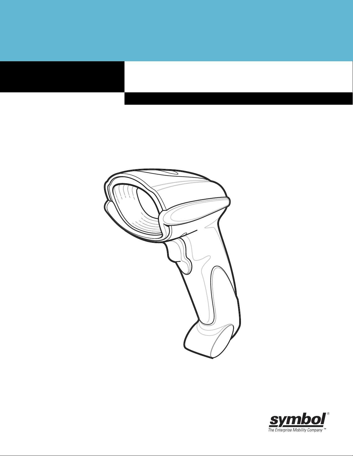
Figure 1-1
DS6708 Digital Scanner
Page 24

1 - 2 DS6708 Digital Scanner Product Reference Guide
Supported Interfaces
The DS 6708 digital scanner supports:
•
Keyboard Wedge connection to a host. The host interprets scanned data as keystrokes. This interface
supports the following international keyboards (for Windows® environment): North America, German,
French, French Canadian, Spanish, Italian, Swedish, UK English, Portuguese-Brazilian, and Japanese.
•
Standard RS-232 connection to a host. Scan bar code menus to set up proper communication of the
digital scanner with the host.
•
USB connection to a host. The digital scanner autodetects a USB host and defaults to the HID keyboard
interface type. Select other USB interface types by scanning programming bar code menus.This
interface supports the following international keyboards (for Windows® environment): North America,
German, French, French Canadian, Spanish, Italian, Swedish, UK English, Portuguese-Brazilian, and
Japanese.
•
Connection to IBM 468X/469X hosts. Scan bar code menus to set up communication of the digital
scanner with the IBM terminal.
•
Wand Emulation connection to a host. The digital scanner is connected to a portable data terminal, a
controller, or host which collects the data as wand data and decodes it.
•
Scanner Emulation connection to a host. The digital scanner is connected to a portable data terminal, a
controller which collects the data and interprets it for the host.
•
Synapse capability which allows connection to a wide variety of host systems using a Synapse and
Synapse adapter cable. The digital scanner autodetects the host.
•
Configuration via 123Scan.
Unpacking
Remove the digital scanner from its packing and inspect it for damage. If the digital scanner was damaged in
transit, call the Symbol Global Interaction Center at one of the telephone numbers listed on page xiv. KEEP
THE PACKING. It is the approved shipping container; use this to return the equipment for servicing.
Page 25
Setting Up the Digital Scanner
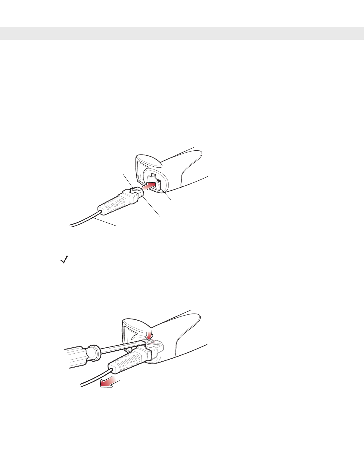
Installing the Interface Cable
1. Plug the interface cable modular connector into the cable interface port on the bottom of the scanner
handle. (See Figure 1-2.)
2. Gently tug the cable to ensure the connector is properly secured.
3. Connect the other end of the interface cable to the host (see the specific host chapter for information on
host connections).
Clip
Getting Started 1 - 3
Cable interface port
Interface cable modular
To host
Figure 1-2
Installing the Cable
NOTE Different cables are required for different hosts. The connectors illustrated in each host
chapter are examples only. Connectors vary from those illustrated, but the steps to connect the
digital scanner remain the same.
connector
Removing the Interface Cable
1. Using the tip of a screwdriver , depress the cable’s modular connector clip.
Figure 1-3
2. Carefully slide out the cable.
3. Follow the steps for Installing the Interface Cable to connect a new cable.
Removing the Cable
Page 26
1 - 4 DS6708 Digital Scanner Product Reference Guide
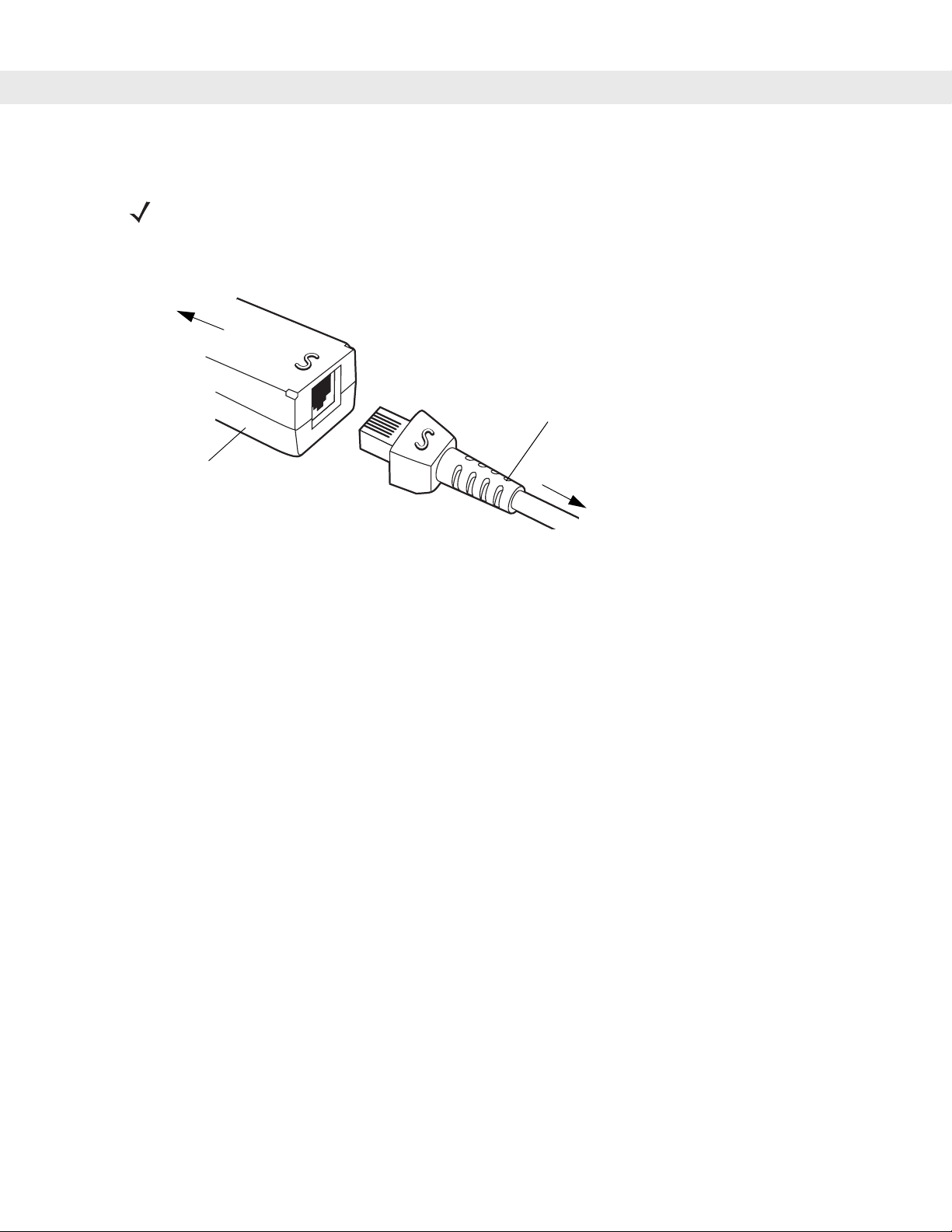
Connecting a Synapse Cable Interface (DS6708 0nly)
NOTE Refer to the Synapse Interface Guide provided with the Synapse cable for detailed setup
instructions
Symbol’s Synapse Smart Cables enable interfacing to a variety of hosts. The Synapse cable has built-in
intelligence to detect that host.
To host
Synapse
Smart Cable
.
Synapse Adapter Cable
To digital scanner
Figure 1-4
1. Plug the Synapse adapter cable (p/n 25-32463-xx) into the bottom of the digital scanner, as described in
Synapse Cable Connection
Installing the Interface Cable on page 1-3.
2. Align the ‘S’ on the Synapse adapter cable with the ‘S’ on the Synapse Smart Cable and plug the cable in.
3. Connect the other end of the Synapse Smart Cable to the host.
Connecting Power (if required)
If the host does not provide power to the digital scanner, connect an external power supply to the digital
scanner:
1. Connect the interface cable to the bottom of the digital scanner, as described in Installing the Interface
Cable on page 1-3.
2. Connect the other end of the interface cable to the host (refer to the host manual to locate the correct port).
3. Plug the power supply into the power jack on the interface cable. Plug the other end of the power supply
into an AC outlet.
Configuring the Digital Scanner
To configure the digital scanner, use the bar codes included in this manual, or the 123Scan configuration
program.
See Chapter 4, User Preferences & Miscellaneous Digital Scanner Options and Chapter 5, Decoding
Preferences for information about programming the digital scanner using bar code menus. Also see each
host-specific chapter to set up connection to a specific host type.
See Chapter 12, 123Scan to configure the digital scanner using the configuration program. A help file is
available in the program.
Page 27
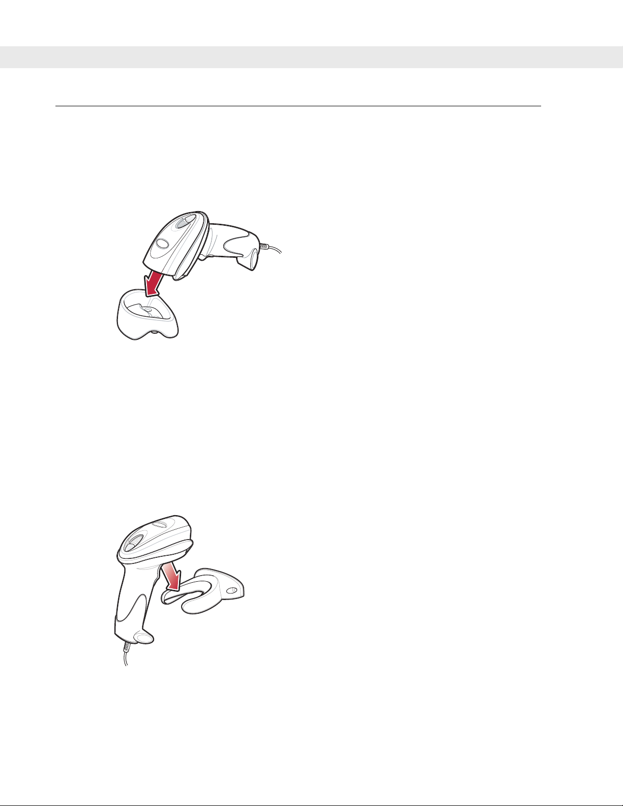
Mounting the Digital Scanner
Desk Mount
Use the optional desk mount for convenient and protective placement of the digital scanner on a flat surface.
Simply place the mount on the surface. The rubber feet hold the mount securely in place when inserting and
removing the digital scanner.
Getting Started 1 - 5
Figure 1-5
The desk mount can also be secured to a desk surface by inserting two screws* appropriate for the mounting
surface through the screw holes of the desk mount, and into the surface. The desk mount ca n be screwed onto
the surface with or without the rubber feet.
*The recommended screws are two #6 screws (5/8” long).
Inserting the Digital Scanner in the Desk Mount
Wall Mount
To use the optional wall mount to mount the digital scanner on a wall, place the mount in th e desired location
on the wall and secure by inserting two screws* appropriate for the mounting surface through the screw holes
on the mount, and into the surface. Insert the digital scanner into the mount as shown.
Figure 1-6
*The recommended screws are two #6 screws (1” long) and two #6 washers.
Securing the Wall Mount
Page 28
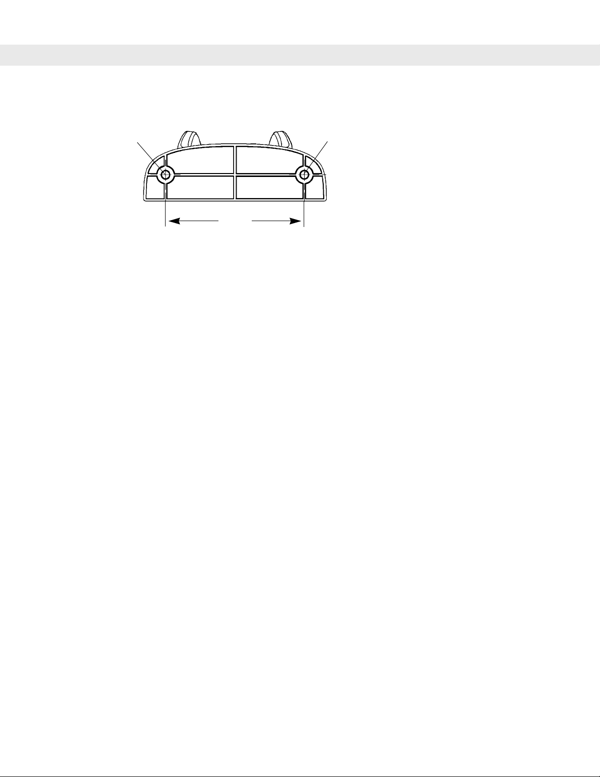
1 - 6 DS6708 Digital Scanner Product Reference Guide
For convenience, print this page and use the template below for mounting hole locations.
Insert mounting
screw
Figure 1-7
Insert mounting
screw
2.98”
Wall Mounting Template
Page 29
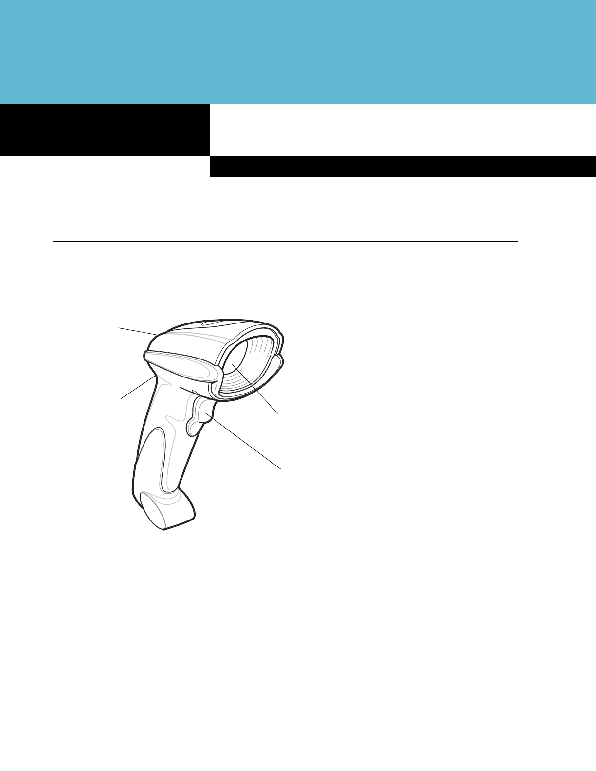
Chapter 2 Scanning
Introduction
This chapter provides beeper and LED definitions, technique s invo lve d in sca nn ing ba r cod e s, ge ne r al
instructions and tips about scanning, and decode zone diagrams.
LED
Beeper
Chapter 2
Scanning
Figure 2-8
Scan
Window
Trigger
Parts
Page 30

2 - 2 DS6708 Digital Scanner Product Reference Guide
Beeper Definitions
The digital scanner issues different beep sequences and patterns to indicate status. Table 2-1 defines beep
sequences that occur during both normal scanning and while programming the digital scanner.
Table 2-1
Standard Use
Low/medium/high beeps Power up.
Short high beep A bar code symbol was decoded (if decode beeper is enabled).
4 long low beeps A transmission error was detected in a scanned symbol. The data is ignored. This
5 low beeps Conversion or format error.
Low/high/low beeps ADF transmit error. See Chapter 14, Advanced Data Formatting.
High/high/high/low beeps RS-232 receive error.
Parameter Menu Scanning
Low/high/low/high beeps Out of host parameter storage space. Scan Set Default Parameter on page 4-4.
Short high beep Correct entry scanned or correct menu sequence performed.
Low/high beeps Input error; incorrect bar code, programming sequence, or Cancel scanned;
High/low beeps Keyboard parameter selected. Enter value using numeric bar codes.
Beeper Definitions
Beeper Sequence Indication
occurs if the digital scanner is not properly configured. Check option setting.
remain in ADF program mode.
High/low/high/low beeps Successful program exit with change in parameter setting.
Code 39 Buffering
High/low beeps New Code 39 data was entered into the buffer.
3 long high beeps Code 39 buffer is full.
Low/high/low beeps The Code 39 buffer was erased or there was an attempt to clear or tran smit an empty
buffer.
Low/high beeps A successful transmission of buffered data.
Macro PDF
2 long low beeps
3 long low beeps Out of memory. There is not enough buffer space to store the current MPDF symbol.
4 long low beeps Bad symbology. Scanned a 1D or 2D bar code in a MPDF sequence, a duplicate
5 long low beeps Flushing MPDF buffer.
File ID error. A bar code not in the current MPDF sequence was scanned.
MPDF label, a label in an incorrect order, or trying to transmit an empty or illegal MPDF
field.
Page 31

Scanning 2 - 3
Table 2-1
Fast warble beep Aborting MPDF sequence.
Low/high beeps Flushing an already empty MPDF buffer.
ADF Programming: Normal Data Entry. Duration of tones are short.
High/low beeps Enter another digit. Add leading zeros to the front if necessary.
Low/low beeps Enter another alphabetic character or scan the End of Message bar code.
High/high beeps Enter another criterion or action, or scan the Save Rule bar code.
High/low/high/low beeps Rule saved. Rule entry mode exited.
High/low/low beeps All criteria or actions cleared for current rule, continue entering rule.
Low beep Delete last saved rule. The current rule is left intact.
Low/high/high beeps All rules are deleted.
ADF Programming: Error Indications. Duration of tones are very long.
Low/high/low/high beeps Out of rule memory. Erase some existing rules, then try to save rule again. (It is not
Low/high/low beeps Cancel rule entry. Rule entry mode exite d because of an error or the user asked to e xit
Beeper Definitions (Continued)
Beeper Sequence Indication
necessary to re-enter the current rule.)
rule entry.
Low/high beeps Entry error, wrong bar code scanned. Re-enter criterion or action. All previously
entered criteria and actions are retained. Criteria or action list is too long for a rule.
Host Specific
USB only
4 short high beeps Digital scanner has not completed initialization. Wait several seconds and scan again.
Low/medium/high beeps
upon scanning a USB device
type
Low/medium/high beeps
occur more than once.
RS-232 only
1 short high beep A <BEL> character is received and Beep on <BEL> is enabled.
Communication with the bus must be established before the digital scanner can
operate at the highest power level.
The USB bus can put the digital scanner in a state where power to the digit al scanner
is cycled on and off more than once. This is normal and usually happens when the PC
cold boots.
Page 32

2 - 4 DS6708 Digital Scanner Product Reference Guide
LED Definitions
In addition to beep sequences, the digital scanner uses a two-color LED to indicate st atus. Ta ble 2-2 defines
LED colors that display during scanning.
Table 2-2
Off No power is applied to the digital scanner, or the digital scanner is on and ready to
Green A bar code was successfully decoded.
Red A data transmission error or digital scanner malfunction occurred.
Standard LED Definitions
LED Indication
scan.
Scanning in Hand-Held Mode
Install and program the digital scanner (see Setting Up the Digital Scanner on page 1-3). For assistance,
contact the local supplier or the local Symbol Global Interaction Center.
Scanning with the Digital Scanner
1. Ensure all connections are secure (see the appropriate host chapter.)
2. Aim the digital scanner at the bar code.
Figure 2-9
3. When the digital scanner senses movement, in its default Auto Aim trigger mode, it projects a red laser
aiming pattern (shown in Figure 2-10) which allows positioning the bar code or object within the field of
view. (To turn off the default Auto Aim trigger mode, see Trigger Mode on page 4-8.)
Figure 2-10
If necessary, the digital scanner turns on its red LEDs to illuminate the target bar code.
Scanning in Hand-Held Mode
Laser Aiming Pattern
Page 33

Scanning 2 - 5
4. Center the symbol in any orientation within the aiming pattern. Be sure the entire symbol is within the
rectangular area formed by the brackets in the pattern.
1D bar code
Linear bar code
Symbol
Aiming Pattern
2D bar code
PDF417 symbol
Figure 2-11
Centering Symbol in Aiming Pattern
5. Hold the trigger until the digital scanner beeps, indicating the bar code is successfully decoded. For more
information on beeper and LED definitions, see Tab le 2-1 and Table 2-2.
This process usually occurs instantaneously. S teps 2 - 4 are repeated on poor quality o r difficult bar cod es, until
the bar code is decoded, the trigger is released, or the Decode Session Timeout is reached.
Aiming
Hold the digital scanner between two and nine inches (depending on symbol density; see Decode Zones on
page 2-7) from the symbol, centering the aiming pattern cross hairs on the symbol.
The aiming pattern is smaller when the digital scanner is closer to the symbol an d larger when it is farther from
the symbol. Scan symbols with smaller bars or elements (mil size) closer to the digital scanner, a nd those with
larger bars or elements (mil size) farther from the digital scanner.
The digital scanner can also read a bar code presented within the aiming pattern but not centered. The top
examples in Figure 2-12 show acceptable aiming options, while the bottom examples can not be decoded.
012345
012345
Figure 2-12
012345
Acceptable and Incorrect Aiming
012345
Page 34

2 - 6 DS6708 Digital Scanner Product Reference Guide
Scanning in Hands-Free Mode
The optional Intellistand adds greater flexibility to scanning operation. When the digital scanner is seated in the
stand’s “cup,” the digital scanner’s built-in sensor places the digital scanner in hands-free mo de. When the
digital scanner is removed from the stand it operates in its normal hand-held mode.
Scanner
Holder (Cup)
Angle Adjustment Knob
Height Adjustment Knob
Figure 2-13
Inserting the Digital Scanner in the Intellistand
To operate the digital scanner in the IntelliStand:
1. Ensure the digital scanner is properly connected to the host (see the appropriate host chapter for
information on host connections).
2. Insert the digital scanner in the Intellistand by placing the front of the digital scanner into the stand’s “cup”
(see Figure 2-13).
3. Use the Intellistand’s adjustment knobs to adjust the height and angle of the digital scanner.
4. Center the symbol in the aiming pattern. The entire symbol must be within the brackets.
5. Upon successful decode, the digital scanner beeps and the LED turns green. For more information on
beeper and LED definitions, see Table 2-1 and Table 2-2.
Page 35

Decode Zones
Scanning 2 - 7
Note: Typical performance at 68˚F (20˚C)
on high quality symbols.
Top of
scanner
5 mil Code 39
2.8
2.6
0.6
1.0
In.
0
cm
2
0 5.1 10.1 15.2 20.3 25.4 30.5 35.6
5.8
Postnet
100% 13 mil UPC
20 mil Code 39
4
6 8 10 12 14
Depth of Field
Figure 2-14
DS6708 Digital Scanner Decode Zone for 1D Bar Codes
Note: Typical performance at 68˚F (20˚C)
on high quality symbols.
Top of
scanner
6.6 mil PDF417
cm
3.4
10 mil QR Code
2.6
2.3 7.5
2.3
2.1
1.5
In.
0
0
2
5.1
10 mil MicroPDF
10 mil Data Matrix
10 mil PDF417
4
10.1
5.7
6.8
35 mil Maxicode
6810
15.2 20.3 25.4
Depth of Field
Figure 2-15
DS6708 Digital Scanner Decode Zone for 2D Bar Codes
8.0
12.5
8.9
14.0
16
40.6
18
45.7
12
30.5
20
50.8
12.8
14
35.6
21.0
22
55.9
In. cm
3
2
1
0
1
2
3
7.6
5.1
2.5
0
2.5
5.1
7.6
In. cm
15.2
6
4
10.1
5.1
2
0
0
5.1
2
4
10.1
6
15.2
W
d
h
o
F
e
d
W
i
d
t
h
o
f
F
i
e
l
d
i
t
f
i
l
Page 36

2 - 8 DS6708 Digital Scanner Product Reference Guide
Page 37

Chapter 3 Maintenance & Technical Specifications
Introduction
This chapter provides suggested scanner maintenance, troubleshooting, technical specifications, and signal
descriptions (pinouts).
Maintenance
Cleaning the scan window is the only maintenance required. A dirty window can affect scanning accuracy.
•
Do not allow abrasive material to touch the window.
•
Remove any dirt particles with a damp cloth.
•
Wipe the window using a tissue moistened with ammonia/water.
Chapter 3
Maintenance & Technical Specifications
•
Do not spray water or other cleaning liquids directly into the window.
Page 38

3 - 2 DS6708 Digital Scanner Product Reference Guide
Troubleshooting
Table 3-1
The aiming pattern does not appear
when pressing the trigger.
Scanner emits short low/short
medium/short high beep sequence
(power-up beep sequence) more than
once.
Troubleshooting
Problem Possible Causes Possible Solutions
No power to the digital scanner. If the configuration requires a power
supply,
re-connect the power supply.
Incorrect host interface cable is used. Connect the correct host interface
cable.
Interface/power cables are loose. Re-connect cables.
Digital scanner is disabled. For Synapse or IBM 468x mode,
enable the digital scanner via the host
interface. Otherwise, see the
technical person in charge of
scanning.
If using RS-232 Nixdorf B mode, CTS
is not asserted.
Aiming pattern is disabled. Enable the aiming pattern. See
The USB bus may put the digital
scanner in a state where power to th e
digital scanner is cycled on and off
more than once.
Assert CTS line.
Decode Aiming Pattern on page 5-5.
Normal during host reset.
Digital scanner emits aiming pattern,
but does not decode the bar code.
Digital scanner emits 4 short high
beeps during decode attempt.
Digital scanner is not programmed for
the correct bar code type.
Bar code symbol is unreadable. Scan test symbols of the same bar
The symbol is not completely inside
aiming pattern.
Digital scanner has not completed
USB initialization.
Program the digital scanner to read
that type of bar code. See Chapter
13, Symbologies.
code type to determine if the bar code
is defaced.
Move the symbol completely within
the aiming pattern.
Wait several seconds and scan ag ain.
Page 39

Maintenance & Technical Specifications 3 - 3
Table 3-1
Digital scanner decodes bar code, but
does not transmit the data to the h ost.
Host displays scanned data
incorrectly.
Troubleshooting (Continued)
Problem Possible Causes Possible Solutions
Digital scanner is not programmed for
the correct host type.
Interface cable is loose. Re-connect the cable.
If 4 long low beeps are heard, a
transmission error occurred.
If 5 low beeps are heard, a conversion
or format error occurred.
If low/high/low beeps are heard, an
invalid ADF rule is detected.
If high/low beeps are heard, the digita l
scanner is buffering Code 39 data.
Digital scanner is not programmed to
work with the host.
Scan the appropriate host type
programming bar code. See the
chapter corresponding to the host
type.
Set the digital scanner's
communication parameters to match
the host's setting.
Configure the digital scanner's
conversion parameters properly.
Program the correct ADF rules.
Normal scanning a Code 39 bar code
and the Code 39 Buffering option is
enabled.
Scan the appropriate host type
programming bar code.
For RS-232, set the digital scanner's
communication parameters to match
the host's settings.
Digital scanner emits
high/high/high/low beeps when not in
use.
Digital scanner emits low/high beeps
during programming.
Digital scanner emits
low/high/low/high beeps during
programming.
For a Keyboard Wedge configuration,
program the system for the correct
keyboard type, and turn off the CAPS
LOCK key.
Program the proper editing options
(e.g., UPC-E to UPC-A Conversion).
RS-232 receive error. Normal during host reset. Otherwise,
set the digital scanner's RS-232 parity
to match the host setting.
Input error or Cancel bar code was
scanned.
Out of ADF parameter storage space. Erase all rules and re-program with
The digital scanner may be out of
Synapse parameter storage space.
Scan the correct numeric bar codes
within range for the parameter
programmed.
shorter rules.
Scan Set Synapse Defaults bar
code for cables no longer in use and
re-program the digital scanner for the
current host interface.
Page 40

3 - 4 DS6708 Digital Scanner Product Reference Guide
Table 3-1
Digital scanner emits low/high/low
beeps.
Digital scanner emits a power-up
beep after changing USB host type.
Digital scanner emits one high beep
when not in use.
Troubleshooting (Continued)
Problem Possible Causes Possible Solutions
NOTE If after performing these checks the digital scanner still experiences problems, contact the
distributor or call the local Symbol Support Center. See page xiii for the telephone numbers.
Technical Specifications
Table 3-2
Technical Specifications
Clearing Code 39 buffer. Normal when scanning the Code 39
Buffering Clear Buffer bar code or
upon attempt to transmit an empty
Code 39 buffer.
The USB bus re-established power to
the digital scanner.
In RS-232 mode, a <BEL> character
was received and Beep on <BEL>
option is enabled.
Normal when changing USB host
type.
Normal when Beep on <BEL> is
enabled and the digital scanner is in
RS-232 mode.
Item Description
Physical Characteristics
Dimensions 6.55 in. x 4.72 in. x 2.82 in. (16.6 cm x 11.9 cm x 7.1 cm)
(H x L x W)
Weight: 6.4 oz. (182 gm)
Voltage & Current: 5 +/-10%VDC @ 350 mA
Color Cash Register White or Twilight Black
Performance Characteristics
Light Source Aiming: 650 nm laser diode
Illumination: 630 nm LED
Field of View
(Vertical x Horizontal)
Roll
Pitch
Yaw
Symbology Decode Capability
1-D UPC/EAN and with supplementals, Code 39, Code 39 Full ASCII, T ri-optic Code 39,
34º (V) x 43º (H)
360º
+/- 65º
+/- 60º
RSS Variants, UCC/EAN 128, Code 128, Code 128 Full ASCII, Code 93, Codabar
(NW1), Interleaved 2 of 5, Discrete 2 of 5, MSI, Codell, IAT A, Bookland EAN, Code 32
PDF417 (& Variants) PDF417, microPDF417 and Composite Codes
Page 41

Maintenance & Technical Specifications 3 - 5
Table 3-2
Postal U.S. Postnet and Planet, U.K., Japan, Australian, and Dutch
2-D MaxiCode, DataMatrix (ECC 200), and QR Code
Nominal Working Distance
(SR - Standard Range focus)
Print Contrast 25% minimum reflectance
Motion Tolerances Horizontal Velocity: 5 in. (12.7 cm) per second
Interfaces Supported RS-232C (Standard, Nixdorf, ICL, & Fujitsu); USB (Standard, IBM SurePOS,
User Environment
Operating Temperature 32º F to 104º F (0º C to 40º C)
Storage Temperature -40º F to 158º F (-40º C to 70º C)
Humidity 5% to 95%, non-condensing
Technical Specifications (Continued)
Item Description
5 mil (Code 39): 1.1 - 6.5 in. (2.8 - 16.5 cm)
13 mil (100% UPC/EAN):0.5 - 9.7 in. (1.3 - 24.6 cm)
20 mil (Code 39): 0.5 - 15.2 in. (1.3 - 38.6 cm)
PDF417 (10 Mil): 0.9 - 7 in. (2.3 - 17.8 cm)
Datamatrix (10 Mil): 1.1 - 7.5 in. (2.8 - 19.1 cm)
Macintosh); IBM 468x/469x; Keyboard Wedge; and, Synapse Connectivity allows for
connectivity to all of the above plus many non-standard interfaces.
Drop Specifications Withstands multiple 5 ft. (1.5 m) drops to concrete
Sealing IP43, Water and Dust resistant
Ambient Light Immunity Immune to normal artificial indoor and natural outdoor (direct sunlight) lighting.
Regulatory
Electrical Safety UL6950-1, CSA C22.2 No. 60950-1, EN60950-1 / IEC60950-1
Laser Safety EN60825-1:1994 +A1: 2002 +A2 :2001, IEC60825-1, 21CFR1040.10 and
21CFR1040.11, CDRH Class II, IEC Class 2
EMI/RFI FCC Part 15 Class B, ICES-003 Class B, CISPR 22, CISPR 24
Medical Electrical Equipment: EN60601-1-2: 2002
RoHS Compliance with RoHS Directive 2002/95/EEC
Mounting Options
(Accessories)
Power Supplies Power supplies are available for applications that do not supply power over the host
Intellistand with adjustable height: 5-10 in. (12.7-25.4 cm) & adjustable angle: 0º - 90º
Desktop & Wall-mount holders are also available.
cable.
Page 42

3 - 6 DS6708 Digital Scanner Product Reference Guide
Digital Scanner Signal Descriptions
Bottom of digital scanner
Cable interface port
Pin 10
Interface cable
modular connector
Figure 3-1
Digital Scanner Cable Pinouts
Pin 1
The signal descriptions in Table 3-3 applies to the connectors on the DS6708 digital scanner and are for
reference only.
Table 3-3
Pin IBM Synapse RS-232
DS6708 Digital Scanner Signal Pin-outs
Keyboard
Wedge
Wand USB
Emulation
1 Reserved SynClock Reserved Reserved Reserved Jump to Pin 6 DBP
2 Power Power Power Power Power Power Power
Scanner
3 Ground Ground Ground Ground Ground Ground Ground
4 IBM_A(+) Reserved TxD KeyClock DBP Reserved SOS
5 Reserved Reserved RxD TermData CTS D + Decode
6 IBM_B(-) SynData RTS KeyDat a RTS Jump to Pin 1 Trigger
7 Reserved Reserved CTS TermClock Reserved D - Enable
8 Reserved Reserved Reserved Reserved Reserved Reserved Reserved
9 Reserved Reserved Reserved Reserved Reserved Reserved Reserved
10 Reserved Reserved Reserved Reserved Reserved Reserved Reserved
Page 43

Chapter 4 User Preferences & Miscellaneous Digital Scanner Options
Introduction
If desired, program the digital scanner to perform various functions, or activate different features. This chapter
describes each user preference feature and provides the programming bar codes necessary for selecting
these features.
The digital scanner ships with the settings shown in Table 4-4 on page 4-2 (also see Appendix A, Standard
Default Parameters for all host device and miscellaneous defaults). If the default values suit requirements,
programming is not necessary.
To set feature values, scan a single bar code or a short bar code sequence. The settings are stored in
non-volatile memory and are preserved even when the digital scanner is powered down.
Chapter 4
User Preferences & Miscellaneous Digital
Scanner Options
NOTE Most computer monitors allow scanning the bar codes directly on the screen. When
scanning from the screen, be sure to set the document magnification to a level where the bar code
can be seen clearly, and bars and/or spaces are not merging.
If not using a USB cable or Synapse cable, select a host type (see each host chapter for specific host
information) after the power-up beeps sound. This is only necessary upon the first power-up when connected
to a new host.
To return all features to default values, scan the Set Default Parameter on page 4-4. Throughout the
programming bar code menus, default values are indicated with asterisks (
* Indicates Default
*High Volume
(00h)
Option Hex Value for
programming via SSI
command
*).
Feature/Option
Page 44

4 - 2 DS6708 Digital Scanner Product Reference Guide
Scanning Sequence Examples
In most cases, scanning one bar code sets the parameter value. For example, to set the beeper tone to high,
scan the High Frequency (beeper tone) bar code listed under Beeper Tone on page 4-5. The digital scanner
issues a fast warble beep and the LED turns green, signifying a successful parameter entry.
Other parameters, such as Serial Response Time-Out or Data Transmission Formats, require scanning
several bar codes. See these parameter descriptions for this procedure.
Errors While Scanning
Unless otherwise specified, to correct an error during a scanning sequence, just re-scan the correct parameter.
User Preferences/Miscellaneous Options Parameter Defaults
Table 4-4 lists defaults for user preferences parameters. There are two ways to change the default values:
•
Scan the appropriate bar codes in this guide. The s e new values replace the standard default values in
memory. To recall the default parameter values, scan the Set Default Parameter on page 4-4.
•
Configure the digital scanner using the 123Scan configuration program (see Chapter 12, 123Scan).
NOTE See Appendix A, Standard Default Parameters for all user preferences, hosts, symbologies,
and miscellaneous default parameters.
Table 4-4
User Preferences
Set Default Parameter All Defaults 4-4
Parameter Scanning ECh Enable 4-4
Beeper Tone 91h Medium 4-5
Beeper Volume 8Ch High 4-6
Power Mode 80h Continuous On 4-6
Time Delay to Low Power Mode 92h 1 Minute 4-7
User Preferences Parameter Defaults
Parameter
Paramete
r Number
Default
Page
Number
Trigger Mode 8Ah Auto Aim 4-8
Picklist Mode F0h 92h Disabled Always 4-9
Decode Session Timeout 88h 9.9 Sec 4-10
Timeout Between Decodes, Same
Symbol
89h 0.6 Sec 4-10
Page 45

User Preferences & Miscellaneous Digital Scanner Options 4 - 3
Table 4-4
User Preferences Parameter Defaults (Continued)
Parameter
Paramete
r Number
Default
Number
Beep After Good Decode 38h Enable 4-11
Miscellaneous Options
Transmit Code ID Character 2Dh None 4-12
Prefix Value 63h, 69h 7013 <CR><LF> 4-13
Suffix 1 Value
Suffix 2 Value
62h, 68h
64h, 6Ah
7013 <CR><LF> 4-13
Scan Data Transm ission Format EBh Data as is 4-14
FN1 Substitution Values 67h, 6Dh Set 4-15
Transmit “No Read” Message 5Eh Disable 4-16
Synapse Interface F0h, ACh Standard Synapse
4-16
Connection
Page
Page 46

4 - 4 DS6708 Digital Scanner Product Reference Guide
User Preferences
Set Default Parameter
Scan this bar code to return all parameters to the default values listed in Table A-1 on page A-1.
*Set All Defaults
Parameter Scanning
Parameter # ECh
To disable decoding of parameter bar codes, scan the Disable Parameter Scanning bar code below. Note
that the Set Defaults parameter bar code can still be decoded. To enable decoding of parameter bar codes,
either scan Enable Parameter Scanning or Set All Defaults.
*Enable Parameter Scanning
(01h)
Disable Parameter Scanning
(00h)
Page 47

User Preferences & Miscellaneous Digital Scanner Options 4 - 5
Beeper Tone
Parameter # 91h
To select a decode beep frequency (tone), scan the Low Frequency, Medium Frequency, or High
Frequency bar code.
Low Frequency
(02h)
*Medium Frequency
(Optimum Setting)
(01h)
High Frequency
(00h)
Page 48

4 - 6 DS6708 Digital Scanner Product Reference Guide
Beeper Volume
Parameter # 8Ch
To select a beeper volume, scan the Low Volume, Medium Volume, or High Volume bar code.
Low Volume
(02h)
Medium Volume
(01h)
*High Volume
(00h)
Power Mode
Parameter # 80h
This parameter determines whether or not power rema ins on af ter a decode attempt. In reduced power mode,
the digital scanner enters into a low power consumption mode to preserve battery life after each decode
attempt. In continuous power mode, power remains on a fter ea ch decode attempt.
*Continuous On
(00h)
Reduced Power Mode
(01h)
Page 49
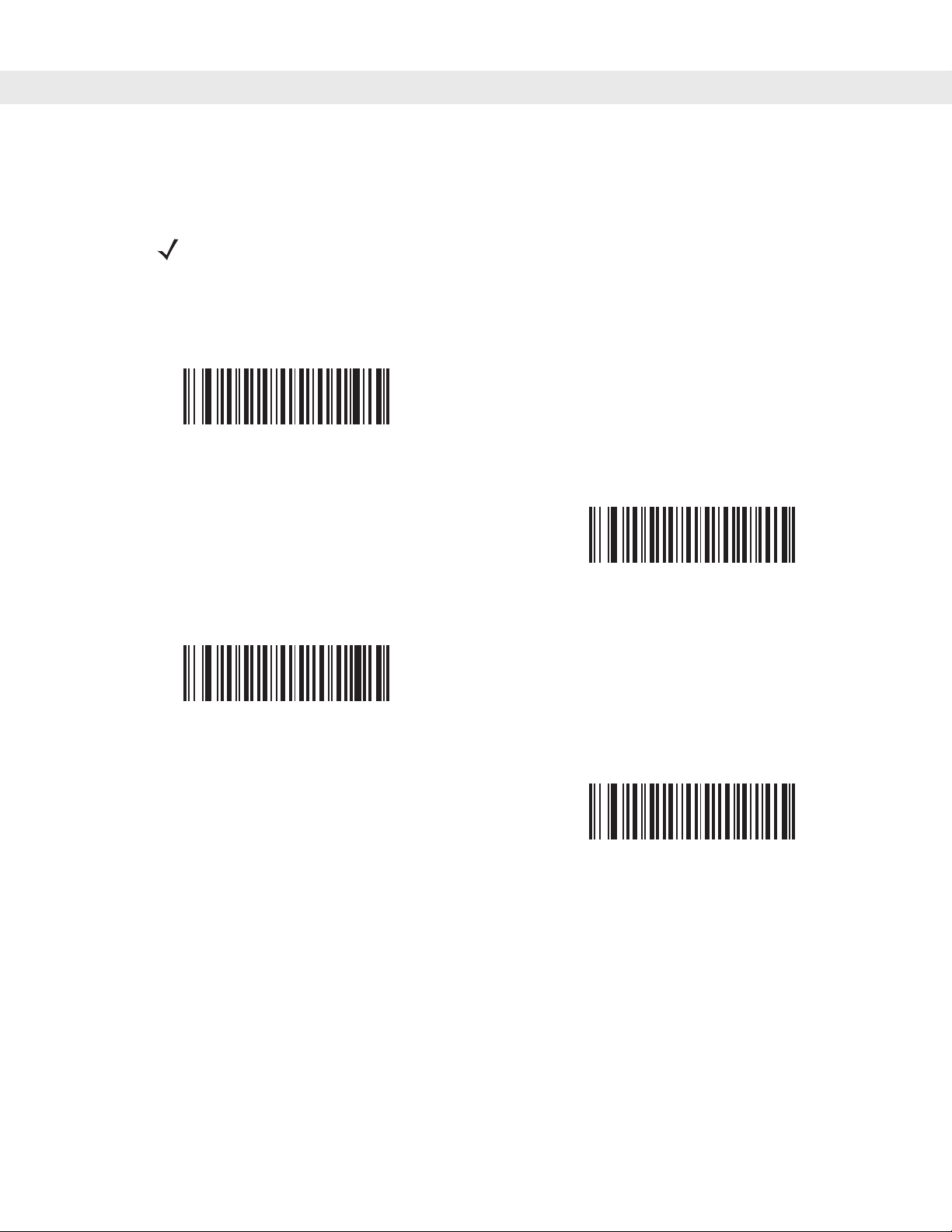
User Preferences & Miscellaneous Digital Scanner Options 4 - 7
Time Delay to Low Power Mode
Parameter # 92h
NOTE This parameter only applies when Power Mode is set to Reduced Power.
This parameter sets the time the digital scann er remains active af ter decoding . The digit al scanner wakes upon
trigger pull or when the host attempts to communicate with the digital scanner.
1 Second
(11h)
*1 Minute
(21h)
5 Seconds
(15h)
5 Minutes
(25h)
Page 50

4 - 8 DS6708 Digital Scanner Product Reference Guide
Time Delay to Low Power Mode (continued)
15 Minutes
(2Bh)
Trigger Mode
Parameter # 8Ah
1 Hour
(31h)
Select one of the following trigger modes for the digital scanner:
•
Level - A trigger pull activates decode processing. Decode processing continues until the bar code is
decoded, the trigger is released, or the Decode Session T imeout is reached.
•
Blink - This trigger mode is used in hands-free (Intellistand) mode. The digita l scanner a ctivates deco de
processing when it detects a bar code in its field of view. Decoding range is reduced in this mode.
•
Auto Aim- This trigger mode turns on the red laser aiming pattern when the digital scanner senses
motion. A trigger pull activates decode processing. After 2 seconds of inactivity the red laser aiming
pattern automatically shuts off.
Level
(00h)
Blink
(07h)
Page 51

Trigger Mode (continued)
*Auto Aim
(09h)
Picklist Mode
Parameter # F0h 92h
Picklist mode enables the digital scanner to decode only bar codes that are aligned under the laser crosshair.
Select one of the following picklist modes for the digital scanner:
•
Disabled Always - Picklist mode is always disabled.
•
Enabled Out of Scanstand - Picklist mode is enabled when the digital scanner is out of Scanstand
mode and disabled when the digital scanner is in Scanstand mode.
User Preferences & Miscellaneous Digital Scanner Options 4 - 9
•
Enabled Always- Picklist mode is always enabled.
*Disabled Always
(00h)
Enabled Always
(02h)
Enabled Out of Scanstand
(01h)
Page 52

4 - 10 DS6708 Digital Scanner Product Reference Guide
Decode Session Timeout
Parameter # 88h
This parameter sets the maximum time decode processing continues during a scan attempt. It is
programmable in 0.1 second increments from 0.5 to 9.9 seconds. The default timeout is 9.9 seconds.
To set a Decode Session Timeout, scan the bar code below. Next, scan two numeric bar codes from Appendix
D, Numeric Bar Codes that correspond to the desired on time. Single digit numbers must have a leading zero.
For example, to set a Decode Session Timeout of 0.5 seconds, scan the bar code below, then scan the 0 and
5 bar codes. To correct an error or change the selection, scan Cancel on page D-2.
Decode Session Timeout
Timeout Between Decodes, Same Symbol
Parameter # 89h
This option is used in hands-free (Intellistand) mode to prevent the beeper from continuously beeping when a
symbol is left in the digital scanner’s field of view. It is programmable in 0.1 second increments from 0.0 to 9.9
seconds. The default interval is 0.6 seconds.
To select the timeout between decodes for the same symbol, scan the bar code below, then scan two numeric
bar codes from Appendix D, Numeric Bar Codes that correspond to the desired interval, in 0.1 second
increments.
Timeout Between Decodes, Same Symbol
Page 53

User Preferences & Miscellaneous Digital Scanner Options 4 - 11
Beep After Good Decode
Parameter # 38h
Scan a bar code below to select whether or not the digital scanner beeps after a good decode. If selecting Do
Not Beep After Good Decode, the beeper still operates during parameter menu scanning and to indicate
error conditions.
*Beep After Good Decode
(Enable)
(01h)
Do Not Beep After Good Decode
(Disable)
(00h)
Page 54

4 - 12 DS6708 Digital Scanner Product Reference Guide
Miscellaneous Scanner Parameters
Transmit Code ID Character
Parameter # 2Dh
A Code ID character identifies the code type of a scanned bar code. This is useful when the digital scanner is
decoding more than one code type. In addition to any single character prefix already selected, the Code ID
character is inserted between the prefix and the decoded symbol.
Select no Code ID character, a Symbol Code ID character, or an AIM Code ID character. For Code ID
Characters, see Symbol Code Identifiers on page B-1 and AIM Code Identifiers on page B-3.
Symbol Code ID Character
(02h)
*None
(00h)
AIM Code ID Character
(01h)
Page 55

User Preferences & Miscellaneous Digital Scanner Options 4 - 13
Prefix/Suffix Values
Key Category Parameter # P = 63h, S1 = 62h, S2 = 64h
Decimal Value Parameter # P = 69h, S1 = 68h, S2 = 6Ah
A prefix and/or one or two suffixes can be appended to scan data for use in data editing. To set a value for a
prefix or suffix, scan a four-digit number (i.e., four bar codes from Appendix D, Numeric Bar Codes) that
corresponds to that value. See Table E-1 on page E-1 for the four-digit codes.
When using host commands to set the prefix or suf fix, set the ke y ca tegory parameter to 1, then set the 3-digit
decimal value. See Table E-1 on page E-1 for the four-digit codes.
To correct an error or change a selection, scan Cancel on page D-2.
NOTE To use Prefix/Suffix values, first set the Scan Data Transmission Format on page 4-14.
Scan Prefix
(07h)
Scan Suffix 2
(08h)
Scan Suffix 1
(06h)
Data Format Cancel
Page 56
4 - 14 DS6708 Digital Scanner Product Reference Guide
Scan Data Transmission Format
Parameter # EBh
To change the scan data format, scan one of the fo llowing eig ht bar codes co rresponding to the desired for mat.
NOTE If using this parameter do not use ADF rules to set the prefix/suffix.
To set values for the prefix and/or suffix, see Prefix/Suffix Values on page 4-13.
*Data As Is
(00h)
<DATA> <SUFFIX 2>
(02h)
<PREFIX> <DA TA >
(04h)
<DATA> <SUFFIX 1>
(01h)
<DATA> <SUFFIX 1> <SUFFIX 2>
(03h)
Page 57

User Preferences & Miscellaneous Digital Scanner Options 4 - 15
Scan Data Transmission Format (continued)
<PREFIX> <DATA> <SUFFIX 2>
(06h)
<PREFIX> <DATA> <SUFFIX 1>
(05h)
<PREFIX> <DATA> <SUFFIX 1> <SUFFIX 2>
(07h)
FN1 Substitution Values
Key Category Parameter # 67h
Decimal Value Parameter # 6Dh
The Wedge and USB HID Keyboard hosts support a FN1 Substitution feature. When enabled any FN1
character (0x1b) in an EAN128 bar code is substituted with a value. This value defaults to 7013 (Enter Key).
When using host commands to set the FN1 substitution value, set the key category parameter to 1, then set
the 3-digit keystroke value. See the ASCII Character Set table for the currently installed host interface for the
desired value.
To select a FN1 substitution value via bar code menus:
1. Scan the bar code below.
Set FN1 Substitution Value
2. Look up the keystroke desired for FN1 Substitution in the ASCII Character Set table for the currently
installed host interface. Enter the 4-digit ASCII Value by sca nning each digit in Appendix D, Numeric Bar
Codes.
To correct an error or change the selection, scan Cancel.
To enable FN1 substitution for USB HID keyboard, scan the Enable FN1 Substitution bar code on page 4-15.
Page 58

4 - 16 DS6708 Digital Scanner Product Reference Guide
Transmit “No Read” Message
Parameter # 5Eh
Scan a bar code below to select whether or not to transmit a No Read message. When enabled, the characters
NR are transmitted when a bar code is not decoded. When disabled, if a symbol does not decode, nothing is
sent to the host.
Enable No Read
(01h)
*Disable No Read
(00h)
Synapse Interface
Parameter # F0h, ACh
The auto-detection of a Synapse cable varies in duration depending on the type of Synapse connection. If a
digital scanner is connected to another scanner using a Synapse cable, use the Auxiliary Synapse Port
connection. In all other cases, where the cable is used, the default setting is recommended.
To disconnect and reconnect the digital scanner from a Synapse cable that is connected to a live host via a
Synapse, use the "Plug and Play" setting. Do not change this setting from the default if an on-board wedge
host is enabled.
*Standard Synapse Connection
(01h)
Page 59

Synapse Interface (continued)
“Plug and Play” Synapse Connecti on
(0Ah)
User Preferences & Miscellaneous Digital Scanner Options 4 - 17
Auxiliary Synapse Port Connection
(32h)
Page 60

4 - 18 DS6708 Digital Scanner Product Reference Guide
Page 61

Chapter 5 Decoding Preferences
Introduction
If desired, program the digital scanner to perform various functions, or activate different features. This chapter
describes decoding preference features and provides the prog ramming ba r codes for selectin g these features.
The digital scanner ship s with the settings sh own in the Decoding Preferences Paramete r Defaults on page 5-2
(also see Appendix A, Standard Default Parameters for all host device and miscellaneous defaults). If the
default values suit requirements, programming is not necessary.
To set feature values, scan a single bar code or a short bar code sequence. The settings are stored in
non-volatile memory and are preserved even when the digital scanner is powered down.
Chapter 5
NOTE Most computer monitors allow scanning the bar codes directly on the screen. When
scanning from the screen, be sure to set the document magnification to a level where the bar code
can be seen clearly, and bars and/or spaces are not merging.
Decoding Preferences
If not using a USB cable, select a host type (see each host chapter for specific host information) after the
power-up beeps sound. This is only necessary upon the first power-up when connected to a new host.
To return all features to default values, scan the Set Default Parameter on page 4-4. Throughout the
programming bar code menus, default values are indicated with asterisks (
* Indicates Default
Scanning Sequence Examples
In most cases scanning one bar code sets the parameter valu e. For example, to disable the decode aiming
pattern, scan the Disable Decode Aiming Pattern bar code listed under Decode Aiming Pa ttern on p age 5-5.
The digital scanner issues a fast warble beep and the LED turns green, signifying a successful parameter
entry.
Other parameters require scanning several bar codes. See these parameter descriptions for this procedure.
*Enable Decode Aiming Pattern
(02h)
*).
Feature/Option
Option Hex Value
for programming
via SSI command
Page 62

5 - 2 DS6708 Digital Scanner Product Reference Guide
Errors While Scanning
Unless otherwise specified, to correct an error during a scanning sequence, just re-scan the correct parameter.
Decoding Preferences Parameter Defaults
Table 5-5 lists the defaults for decoding preferences parameters. There are two ways to change the default
values:
•
Scan the appropriate bar codes in this guide. The s e new values replace the standard default values in
memory. To recall the default parameter values, scan the Set Default Parameter on page 4-4.
•
Configure the digital scanner using the 123Scan configuration program (see Chapter 12, 123Scan).
NOTE See Appendix A, Standard Default Parameters for all user preferences, hosts, symbologies,
and miscellaneous default parameters.
Table 5-5
Decoding Options
Decoding Illumination F0h 2Ah Enable 5-3
Illumination Bank Control F1h 3Bh Full Illumination 5-4
Decode Aiming Pattern F0h 32h Enable 5-5
Decoding Preferences Parameter Defaults
Parameter Parameter Number Default
Page
Number
Page 63

Decoding Preferences
The parameters in this chapter control bar code decoding characteristics.
Decoding Illumination
Parameter # F0h, 2Ah
Selecting Enable Decoding Illumination causes the digital scanner to flash illumination to aid decoding.
Select Disable Decoding Illumination to prevent the digital scanner from using decoding illumination.
Enabling illumination usually results in superior images. The effectiveness of the illumination decreases as the
distance to the target increases.
*Enable Decoding Illumination
(01h)
Decoding Preferences 5 - 3
Disable Decoding Illumination
(00h)
Page 64

5 - 4 DS6708 Digital Scanner Product Reference Guide
Illumination Bank Control
Parameter # F1h 3Bh
Selecting an illumination bank control parameter allows the user to control the illumination banks on the scan
engine.
•
Full (0) (default): The full illumination system is enabled.
•
Auto (1): The illumination system automatically switches from left to right banks.
•
Left (2): The left bank is enabled.
•
Right (3): The right bank is enabled.
*Full Illumination
(00h)
Left Illumination
(02h)
Auto Illumination
(01h)
Right Illumination
(03h)
Page 65

Decoding Preferences 5 - 5
Decode Aiming Pattern
Parameter # F0h, 32h
This parameter only applies when in Decode Mode. Select Enable Decode Aiming Pattern to project the
aiming pattern during bar code capture, or Disable Decode Aiming Pattern to turn the aiming pattern off.
NOTE With picklist enabled, the decode aiming pattern flashes even when the Decode Aiming
Pattern is disabled.
*Enable Decode Aiming Pattern
(02h)
Disable Decode Aiming Pattern
(00h)
Page 66

5 - 6 DS6708 Digital Scanner Product Reference Guide
Page 67

Chapter 6 USB Interface
Introduction
This chapter describes how to set up the digit al scanner with a USB host. The digit al scanner con nects d irectly
to a USB host, or a powered USB hub, and is powered by it. No additional power supply is required.
Chapter 6
USB Interface
Throughout the programming bar code menus, default values are indicated with asterisks (
*Indicates Default
NOTE Most computer monitors allow scanning the bar codes directly on the screen. When
scanning from the screen, be sure to set the document magnification to a level where the bar code
can be seen clearly, and bars and/or spaces are not merging.
*North American Standard USB Keyboard
Feature/Option
*).
Page 68

6 - 2 DS6708 Digital Scanner Product Reference Guide
Connecting a USB Interface
USB Series A
Connector
Figure 6-1
USB Connection
Interface Cable
The digital scanner connects with USB-capable hosts including:
•
Desktop PCs and notebooks
- Apple™ iMac, G4, iBooks (North America only)
- IBM SurePOS terminals
•
Sun, IBM, and other network computers that support more than one keyboard.
The following operating systems support the digital scanner through USB:
• Windows
• MacOS 8.5 - MacOS 10.3
• IBM 4690 OS.
®
98, 2000, ME, XP
The digital scanner also interfaces with other USB hosts which support USB Human Interface Devices (HID).
For more information on USB technology, hosts, and peripheral devices, visit www.symbol.com/usb.
To set up the digital scanner:
NOTE Interface cables vary depending on configuration. The connectors illustrated in Figure 6-1
are examples only. The connectors may be different than those illustrated, but the steps to
connect the scanner remain the same.
1. Connect the modular connector of the USB interface ca ble to the cable interface port on the digital scanner
(see Installing the Interface Cable on page 1-3).
2. Plug the series A connector in the USB host or hub, or plug the Plus Power connector in an available port
of the IBM SurePOS terminal.
3. Select the USB device type by scanning the appropriate ba r cod e from USB Device Type on page 6-4.
Page 69

4. On first installation when using Windows, the software prompts to select or install the Human Interface
Device driver. To install this driver, provided by Windows, click Next through all the choices and click
Finished on the last choice. The digital scanner powers up during this installation.
5. To modify any other parameter options, scan the appropriate bar codes in this chapter.
If problems occur with the system, see Troubleshooting on page 3-2.
USB Parameter Defaults
Table 6-1 lists the defaults for USB host parameters. To change any option, scan the appropriate bar code(s)
provided in the Parameter Descriptions section beginning on page 6-4.
NOTE See Appendix A, Standard Default Parameters for all user preferences, hosts, symbologies,
and miscellaneous default parameters.
USB Interface 6 - 3
Table 6-1
USB Host Parameters
USB Device Type HID Keyboard
USB Country Keyboard Types (Country
Codes)
USB Keystroke Delay No Delay 6-7
USB CAPS Lock Override Disable 6-7
USB Ignore Unknown Characters Enable 6-8
Emulate Keypad Disable 6-8
Emulate Keypad with Leading Zero Disable 6-9
USB FN1 Substitution Disable 6-9
Function Key Mapping Disable 6-10
Simulated Caps Lock Disable 6-10
Convert Case None 6-11
USB Interface Parameter Defaults
Parameter Default
6-4
Emulation
North American 6-5
Page
Number
Page 70

6 - 4 DS6708 Digital Scanner Product Reference Guide
USB Host Parameters
USB Device Type
Select the desired USB device type.
NOTE When changing USB Device Types, the digital scanner automatically resets. The digital
scanner issues the standard startup beep sequences.
*HID Keyboard Emulation
IBM Hand-Held USB
Simple COM Port Emulation
IBM Table Top USB
USB OPOS Handheld
Page 71

USB Interface 6 - 5
USB Country Keyboard Types - Country Codes
Scan the bar code corresponding to the keyboard type. This setting applies only to the USB HID Keyboard
Emulation device.
NOTE When changing USB country keyboard types the digital scanner automatically resets. The
digital scanner issues the standard startup beep sequences.
*North American Standard USB Keyboard
French Windows
French Canadian Windows 2000/XP
German Windows
French Canadian Windows 95/98
Page 72

6 - 6 DS6708 Digital Scanner Product Reference Guide
USB Country Keyboard Types - Country Codes (continued)
Italian Windows
Spanish Windows
UK English Windows
Portuguese-Brazilian Windows
Swedish Windows
Japanese Windows (ASCII)
Page 73

USB Interface 6 - 7
USB Keystroke Delay
This parameter sets the delay, in milliseconds, between emulated keystrokes. Scan a bar code below to
increase the delay when hosts require a slower transmission of data.
*No Delay
Medium Delay (20 msec)
Long Delay (40 msec)
USB CAPS Lock Override
This option applies only to the HID Keyboard Emulation device. When enabled, the case of the data is
preserved regardless of the state of the Caps Lock key. This setting is always enabled for the Japanese,
Windows (ASCII) keyboard type and can not be disabled.
Override Caps Lock Key
(Enable)
*Do Not Override Caps Lock Key
(Disable)
Page 74

6 - 8 DS6708 Digital Scanner Product Reference Guide
USB Ignore Unknown Characters
This option applies only to the HID Keyboard Emulation device and IBM device. Unknown characters are
characters the host does not recognize. When Send Bar Codes With Unknown Characters is selected, all
bar code data is sent except for unknown characters, and no error beeps sound. When Do Not Send Bar
Codes With Unknown Characters is selected, for IBM devices, bar codes containing at least one unknown
character are not sent to the host, and an error beep sounds. For HID Keyboard Emulation devices, the bar
code characters up to the unknown character are sent, and an error beep sounds.
*Send Bar Codes with Unknown Characters
(Transmit)
Do Not Send Bar Codes with Unknown Characters
(Disable)
Emulate Keypad
When enabled, all characters are sent as ASCII sequences over the numeric keypad. For example ASCII A
would be sent as “ALT make” 0 6 5 “ALT Break”.
*Disable Keypad Emulation
Enable Keypad Emulation
Page 75

USB Interface 6 - 9
Emulate Keypad with Leading Zero
When enabled, character sequences sent over the numeric keypad are sent as ISO characters which have a
leading zero. For example ASCII A would be sent as “ALT MAKE” 0 0 6 5 “ALT BREAK”.
*Disable Keypad Emulation with Leading Zero
Enable Keypad Emulation with Leading Zero
USB Keyboard FN 1 Substitution
This option applies only to the USB HID Keyboard Emulation device. When enabled, this allows replacement
of any FN 1 characters in an EAN 128 bar code with a Key Category and value chosen by the user (see USB
Keyboard FN 1 Substitution on page 6-9 to set the Key Category and Key Value).
Enable
*Disable
Page 76

6 - 10 DS6708 Digital Scanner Product Reference Guide
Function Key Mapping
ASCII values under 32 are normally sent as a control-key sequence s (see Table 6-2 on page 6-12). When this
parameter is enabled, the keys in bold are sent in place of the standard key mapping. Table entries that do not
have a bold entry remain the same whether or not this parameter is enabled.
*Disable Function Key Mapping
Enable Function Key Mapping
Simulated Caps Lock
When enabled, the digital scanner invert s upper and lower case cha racters on the bar code as if the Cap s Lock
state is enabled on the keyboard. This inversion is done reg ardless of the curren t sta te of the keyboard’ s Caps
Lock state.
*Disable Simulated Caps Lock
Enable Simulated Caps Lock
Page 77

Convert Case
When enabled, the digital scanner converts all bar code data to the selected case.
*No Case Conversion
Convert All to Upper Case
USB Interface 6 - 11
Convert All to Lower Case
Page 78

6 - 12 DS6708 Digital Scanner Product Reference Guide
ASCII Character Set for USB
Table 6-2
Prefix/ Suffix Value
USB Prefix/Suffix Values
Full ASCII Code 39
Encode Char.acter
Keystroke
1000 %U CTRL 2
1001 $A CTRL A
1002 $B CTRL B
1003 $C CTRL C
1004 $D CTRL D
1005 $E CTRL E
1006 $F CTRL F
1007 $G CTRL G
1008 $H CTRL H/BACKSPACE
1
1009 $I CTRL I/HORIZONTAL TAB
1010 $J CTRL J
1011 $K CTRL K
1012 $L CTRL L
1013 $M CTRL M/ENTER
1
1
1014 $N CTRL N
1015 $O CTRL O
1016 $P CTRL P
1017 $Q CTRL Q
1018 $R CTRL R
1019 $S CTRL S
1020 $T CTRL T
1021 $U CTRL U
1022 $V CTRL V
1023 $W CTRL W
1024 $X CTRL X
1
The keystroke in bold is sent only if the “Function Key Mapping” is enabled.
Otherwise, the unbolded keystroke is sent.
Page 79

USB Interface 6 - 13
Table 6-2
Prefix/ Suffix Value
USB Prefix/Suffix Values (Continued)
Full ASCII Code 39
Encode Char.acter
1025 $Y CTRL Y
1026 $Z CTRL Z
1027 %A CTRL [/ESC
1028 %B CTRL \
1029 %C CTRL ]
1030 %D CTRL 6
1031 %E CTRL 1032 Space Space
1033 /A !
1034 /B “
1035 /C #
1036 /D $
1037 /E %
Keystroke
1
1038 /F &
1039 /G ‘
1040 /H (
1041 /I )
1042 /J *
1043 /K +
1044 /L ,
1045 - 1046 . .
1047 /O /
1048 0 0
1049 1 1
1050 2 2
1051 3 3
1052 4 4
1
The keystroke in bold is sent only if the “Function Key Mapping” is enabled.
Otherwise, the unbolded keystroke is sent.
Page 80

6 - 14 DS6708 Digital Scanner Product Reference Guide
Table 6-2
Prefix/ Suffix Value
USB Prefix/Suffix Values (Continued)
Full ASCII Code 39
Encode Char.acter
1053 5 5
1054 6 6
1055 7 7
1056 8 8
1057 9 9
1058 /Z :
1059 %F ;
1060 %G <
1061 %H =
1062 %I >
1063 %J ?
1064 %V @
1065 A A
Keystroke
1066 B B
1067 C C
1068 D D
1069 E E
1070 F F
1071 G G
1072 H H
1073 I I
1074 J J
1075 K K
1076 L L
1077 M M
1078 N N
1079 O O
1080 P P
1
The keystroke in bold is sent only if the “Function Key Mapping” is enabled.
Otherwise, the unbolded keystroke is sent.
Page 81

USB Interface 6 - 15
Table 6-2
Prefix/ Suffix Value
USB Prefix/Suffix Values (Continued)
Full ASCII Code 39
Encode Char.acter
1081 Q Q
1082 R R
1083 S S
1084 T T
1085 U U
1086 V V
1087 W W
1088 X X
1089 Y Y
1090 Z Z
1091 %K [
1092 %L \
1093 %M ]
Keystroke
1094 %N ^
1095 %O _
1096 %W `
1097 +A a
1098 +B b
1099 +C c
1100 +D d
1101 +E e
1102 +F f
1103 +G g
1104 +H h
1105 +I i
1106 +J j
1107 +K k
1108 +L l
1
The keystroke in bold is sent only if the “Function Key Mapping” is enabled.
Otherwise, the unbolded keystroke is sent.
Page 82

6 - 16 DS6708 Digital Scanner Product Reference Guide
Table 6-2
Prefix/ Suffix Value
USB Prefix/Suffix Values (Continued)
Full ASCII Code 39
Encode Char.acter
1109 +M m
1110 +N n
1111 +O o
1112 +P p
1113 +Q q
1114 +R r
1115 +S s
1116 +T t
1117 +U u
1118 +V v
1119 +W w
1120 +X x
1121 +Y y
Keystroke
1122 +Z z
1123 %P {
1124 %Q |
1125 %R }
1126 %S ~
1
The keystroke in bold is sent only if the “Function Key Mapping” is enabled.
Otherwise, the unbolded keystroke is sent.
Page 83

USB Interface 6 - 17
Table 6-3
2064 ALT 2
2065 ALT A
2066 ALT B
2067 ALT C
2068 ALT D
2069 ALT E
2070 ALT F
2071 ALT G
2072 ALT H
2073 ALT I
2074 ALT J
2075 ALT K
2076 ALT L
USB ALT Key Character Set
ALT Keys Keystroke
2077 ALT M
2078 ALT N
2079 ALT O
2080 ALT P
2081 ALT Q
2082 ALT R
2083 ALT S
2084 ALT T
2085 ALT U
2086 ALT V
2087 ALT W
2088 ALT X
2089 ALT Y
2090 ALT Z
Page 84

6 - 18 DS6708 Digital Scanner Product Reference Guide
Table 6-4
3000 Right Control Key
3048 GUI 0
3049 GUI 1
3050 GUI 2
3051 GUI 3
3052 GUI 4
3053 GUI 5
3054 GUI 6
3055 GUI 7
3056 GUI 8
3057 GUI 9
3065 GUI A
3066 GUI B
USB GUI Key Character Set
GUI Key Keystroke
3067 GUI C
3068 GUI D
3069 GUI E
3070 GUI F
3071 GUI G
3072 GUI H
3073 GUI I
3074 GUI J
3075 GUI K
3076 GUI L
3077 GUI M
3078 GUI N
3079 GUI O
Note: GUI Shift Keys - The Apple™ iMac keyboard has an
apple key on either side of the space bar. Windows-based
systems have a GUI key to the left of the left AL T key, and to the
right of the right ALT key.
Page 85

USB Interface 6 - 19
Table 6-4
3080 GUI P
3081 GUI Q
3082 GUI R
3083 GUI S
3084 GUI T
3085 GUI U
3086 GUI V
3087 GUI W
3088 GUI X
3089 GUI Y
3090 GUI Z
Note: GUI Shift Keys - The Apple™ iMac keyboard has an
apple key on either side of the space bar. Windows-based
systems have a GUI key to the left of the left AL T key, and to the
right of the right ALT key.
USB GUI Key Character Set (Continued)
GUI Key Keystroke
Page 86

6 - 20 DS6708 Digital Scanner Product Reference Guide
Table 6-5
5001 F1
5002 F2
5003 F3
5004 F4
5005 F5
5006 F6
5007 F7
5008 F8
5009 F9
5010 F10
5011 F11
5012 F12
5013 F13
USB F Key Character Set
F Keys Keystroke
5014 F14
5015 F15
5016 F16
5017 F17
5018 F18
5019 F19
5020 F20
5021 F21
5022 F22
5023 F23
5024 F24
Page 87

USB Interface 6 - 21
Table 6-6
6042 *
6043 +
6044 undefined
6045 6046 .
6047 /
6048 0
6049 1
6050 2
6051 3
6052 4
6053 5
6054 6
USB Numeric Keypad Character Set
Numeric Keypad Keystroke
6055 7
6056 8
6057 9
6058 Enter
6059 Num Lock
Page 88

6 - 22 DS6708 Digital Scanner Product Reference Guide
Table 6-7
7001 Break
7002 Delete
7003 PgUp
7004 End
7005 Pg Dn
7006 Pause
7007 Scroll Lock
7008 Backspace
7009 Tab
7010 Print Screen
7011 Insert
7012 Home
7013 Enter
USB Extended Keypad Character Set
Extended Keypad Keystroke
7014 Escape
7015 Up Arrow
7016 Down Arrow
7017 Left Arrow
7018 Right Arrow
Page 89

Chapter 7 RS-232 Interface
Introduction
This chapter describes how to set up the digital scanner with an RS-232 host. The RS-232 interface is used to
connect the digital scanner to point-of-sale devices, host computer s, or other devices with an availab le RS-232
port (e.g., com port).
If the host is not listed in Table 7-2, refer to the documentation for the host device to set communication
parameters to match the host.
Chapter 7
NOTE The digital scanner uses TTL RS-232 signal levels, which interface with most system
architectures. For system architectures requiring RS-232C signal levels, Symbol offers different
cables providing TTL-to-RS-232C conversion. Contact the Symbol Support Center for more
information.
RS-232 Interface
Throughout the programming bar code menus, default values are indicated with asterisks (
* Indicates Default
NOTE Most computer monitors allow scanning the bar codes directly on the screen. When
scanning from the screen, be sure to set the document magnification to a level where the bar code
can be seen clearly, and bars and/or spaces are not merging.
*Baud Rate 57,600
Feature/Option
*).
Page 90

7 - 2 DS6708 Digital Scanner Product Reference Guide
Connecting an RS-232 Interface
This connection is made directly from the digital scanner to the host computer.
Serial Port Connector to
Host
Power Supply Cable
Interface Cable
Figure 7-1
1. Attach the modular connector of the RS-232 interface cable to the cable interface port on the digital
RS-232 Direct Connection
NOTE Interface cables vary depending on configuration. The connectors illustrated in Figure 7-1
are examples only. The connectors may be different than those illustrated, but the steps to
connect the scanner remain the same.
scanner (see Installing the Interface Cable on page 1-3).
2. Connect the other end of the RS-232 interface cable to the serial port on the host.
3. Connect the power supply to the serial connector end of the RS-23 2 interface cable. Plug the power supply
into an appropriate outlet.
4. Select the RS-232 host type by scanning the appropriate bar code from RS-232 Host Types on page 7-6.
5. To modify any other parameter options, scan the appropriate bar codes in this chapter.
Page 91

RS-232 Parameter Defaults
Table 7-1 lists the defaults for RS-232 host parameters. To change any option, scan the appropriate bar
code(s) provided in the RS-232 Host Parameters section beginning on page 7-4.
NOTE See Appendix A, Standard Default Parameters for all user preferences, hosts, symbologies,
and miscellaneous default parameters.
RS-232 Interface 7 - 3
Table 7-1
RS-232 Host Parameters
RS-232 Host Types Standard 7-6
Baud Rate 9600 7-7
Parity Type None 7-9
Stop Bit Select 1 Stop Bit 7-10
Data Bits 8-Bit 7-10
Check Receive Errors Enable 7-11
Hardware Handshaking None 7-11
Software Handshaking None 7-13
Host Serial Response Time-out 2 Sec 7-15
RTS Line State Low RTS 7-16
Beep on <BEL> Disable 7-16
Intercharacter Delay 0 msec 7-17
RS-232 Host Default Table
Parameter Default
Page
Number
Nixdorf Beep/LED Options Normal Operation 7-18
Ignore Unknown Characters Send Bar Code 7-18
Page 92

7 - 4 DS6708 Digital Scanner Product Reference Guide
RS-232 Host Parameters
V arious RS-232 host s are set u p with their own parameter default settings (Table 7-2). Selecting standard, ICL,
Fujitsu, Wincor-Nixdorf Mode A, Wincor-Nixdorf Mode B, OPOS/JPOS, Olivetti, or Omron sets the defaults
listed below.
Table 7-2
Transmit Code ID Yes Yes Yes Yes Yes Yes
Data T ransmission
Format
Suffix CR (1013) CR (1013) CR (1013) CR (1013) ETX (1002) CR (1013)
Baud Rate 9600 9600 9600 9600 9600 9600
Parity Even None Odd Odd Even None
Hardware
Handshaking
Software
Handshaking
Serial Response
Time-out
Stop B it Select One One One One One One
ASCII Format 8-Bit 8-Bit 8-Bit 8-Bit 7-Bit 8-Bit
Terminal Specific RS-232
Parameter ICL Fujitsu
Data/Suffix Data/Suffix Data/Suffix Data/Suffix Prefix/Data/
RTS/CTS
Option 3
None None None None Ack/Nak None
9.9 Sec. 2 Sec. 9.9 Sec. 9.9 Sec. 9.9 Sec. 9.9 Sec.
None RTS/CTS
Wincor-Nixdorf
Mode A
Option 3
Wincor-Nixdorf
Mode
B/OPOS/JPOS
RTS/CTS
Option 3
Olivetti Omron
Data/Suffix
Suffix
None None
Beep On <BEL> Disable Disable Disable Disable Disable Disable
RTS Line State High Low Low Low = No data
to send
Prefix None None None None STX (1003) None
* In the Nixdorf Mode B, if CTS is Low, scanning is disabled. When CTS is High, the user can scan bar codes.
**If Nixdorf Mode B is scanned without the digital scanner con nected to the proper host, it may appear unable to scan.
If this happens, scan a different RS-232 host type within 5 seconds of cycling power to the digital scanner.
Low High
Page 93

RS-232 Host Parameters (continued)
Selecting ICL, Fujitsu, Wincor-Nixdorf Mode A, Wincor-Nixdorf Mode B, OPOS/JPOS, Olivetti, or Omron
enables the transmission of code ID characters listed in Table 7-3. These code ID characters are not
programmable and are separate from the Transmit Code ID feature. Do not enable the Transmit Code ID
feature for these terminals.
RS-232 Interface 7 - 5
Table 7-3
UPC-A AAA A AA
UPC-E EEC C CE
EAN-8/JAN-8 FF FF B B B FF
EAN-13/JAN-13 FFA A AF
Code 39 C <len> None M M M <len> C <len>
Codabar N <len> None N N N <len> N <len>
Code 128 L <len> None K K K <len> L <len>
I 2 of 5 I <len> None I I I <len> I <len>
Code 93 None None L L L <len> None
D 2 of 5 H <len> None H H H <len> H <len>
UCC/EAN 128 L <len> None P P P <len> L <len>
MSI None None O O O <len> None
Bookland EAN FFA A AF
Terminal Specific Code ID Characters
ICL Fujitsu
Wincor-Nixdorf
Mode A
Wincor-Nixdorf Mode
B/OPOS/JPOS
Olivetti Omron
Trioptic None None None None None None
Code 11 None None None None None None
IATA H<len> None H H None None
Code 32 None None None None None None
Page 94

7 - 6 DS6708 Digital Scanner Product Reference Guide
RS-232 Host Types
To select an RS-232 host interface, scan one of the following bar codes.
Standard RS-232
Wincor-Nixdorf RS-232 Mode A
1
ICL RS-232
Wincor-Nixdorf RS-232 Mode B
Olivetti ORS4500
Omron
1
Scanning Enable RS-232 (No Variant) activates the RS-232 driver, but does not change port settings (e.g.,
parity, data bits, handshaking). Selecting another RS-232 host type bar code changes these settings.
Page 95

RS-232 Interface 7 - 7
RS-232 Host Types (continued)
OPOS/JPOS
Fujitsu RS-232
Baud Rate
Baud rate is the number of bits of data transmitted per second. Set the digital scanner's baud rate to match the
baud rate setting of the host device. Otherwise, data may not re ach the host device or may reach it in disto rted
form.
Baud Rate 600
Baud Rate 2400
Baud Rate 1200
Baud Rate 4800
Page 96

7 - 8 DS6708 Digital Scanner Product Reference Guide
Baud Rate (continued)
*Baud Rate 9600
Baud Rate 19,200
Baud Rate 38,400
Baud Rate 115,200
Baud Rate 57,600
Page 97

RS-232 Interface 7 - 9
Parity
A parity check bit is the most significant bit of each ASCII coded character. Select the parity type according to
host device requirements.
•
Select Odd parity and the p arity bit value is set to 0 or 1, based on dat a, to ensure th at an odd number of
1 bits are contained in the coded character.
•
Select Even parity and the parity bit value is set to 0 or 1, based o n dat a, to ensur e that an e ven number
of 1 bits are contained in the coded character.
•
Select Mark parity and the parity bit is always 1.
•
Select Space pari ty and the parity bit is always 0.
•
Select None when no parity bit is required.
Odd
Mark
*None
Even
Space
Page 98

7 - 10 DS6708 Digital Scanner Product Reference Guide
Stop Bit Select
The stop bit(s) at the end of each transmitted character marks the end of transmission of one character and
prepares the receiving device for the next character in the seri al dat a stream. Th e number of stop bits selected
(one or two) depends on the numbe r the receiving terminal i s programmed to a ccommodate. Set the number of
stop bits to match host device requirements.
2 Stop Bits
*1 Stop Bit
Data Bits
This parameter allows the digital scanner to interface with devices requiring a 7-bit or 8-bit ASCII protocol.
7-Bit
*8-Bit
Page 99

RS-232 Interface 7 - 11
Check Receive Errors
Select whether or not the parity, framing, and overrun of received characters are checked. The parity value of
received characters is verified against the parity parameter selec te d ab ov e.
*Check For Received Errors
Do Not Check For Received Errors
Hardware Handshaking
The data interface consists of an RS-232 port designed to operate either with or without the hardware
handshaking lines, Request to Send (RTS), and Clear to Send (CTS).
If Standard RTS/CTS handshaking is not selected, scan data is transmitted as it becomes available. If
Standard RTS/CTS handshaking is selected, scan data is transmitted according to the following sequence:
•
The digital scanner reads the CTS line for activity. If CTS is asserted, the digital scanner wait s up to Host
Serial Response Time-out for th e host to de-assert the CTS line. If, afte r Host Serial Response Time-out
(default), the CTS line is still asserted, the digital scanner sounds a transmit error, and any scanned data
is lost.
•
When the CTS line is de-asserted, the digital scanner asserts the RTS line and waits up to Host Serial
Response Time-out for the host to assert CTS. When the host asserts CTS, data is transmitted. If, after
Host Serial Response Time-out (default), the CTS line is not asserted, the digital scanner sounds a
transmit error, and discards the data.
•
When data transmission is complete, the digital scanner de-asserts RTS 10 msec after sending the last
character.
•
The host should respond by negating CTS. The digital scanner checks for a de-asserted CTS upon the
next transmission of data.
During the transmission of data, the CTS line should be asserted. If CTS is deasserted for more than 50 ms
between characters, the transmission is aborted, the digi tal scanner sounds a transmission error, and th e dat a
is discarded.
If the above communication sequence fails, the digita l scanner issues an err or indication. In this case, the dat a
is lost and must be rescanned.
If Hardware Handshaking and Software Handshaking are both enabled, Hardware Handshaking takes
precedence.
NOTE The DTR signal is jumpered to the active state.
Page 100

7 - 12 DS6708 Digital Scanner Product Reference Guide
Hardware Handshaking (continued)
•
None: Scan the bar code below if no Hardware Handshaking is desired.
•
Standard RTS/CTS: Scan the bar code below to select Standard RTS/CTS Hardware Handshaking.
•
RTS/CTS Option 1: When RTS/CTS Option 1 is selected, the digital scanner asserts RTS before
transmitting and ignores the state of CTS. The digital scanner de-asserts RTS when the transmission is
complete.
•
RTS/CTS Option 2: When Option 2 is selected, RTS is always high or low (user-programmed logic
level). However, the digital scanner waits for CTS to be asserted before transmitting data. If CTS is not
asserted within Host Serial Response Time-out (default), the digital scanner issues an error indication
and discards the data.
•
RTS/CTS Option 3: When Option 3 is selected, the digital scanner asserts RTS prior to any data
transmission, regardless of the state of CTS. The digital scanner wait s up to Host Serial Response
Time-out (default) for CTS to be asserted. If CTS is not asserted during this time, the digital scanner
issues an error indication and discards the data. The digital scanner de-asserts RTS when transmission
is complete.
*None
RTS/CTS Option 1
Standard RTS/CTS
 Loading...