

Page 1

AR 400 Reader
User’s Manual
Published: June 21, 2004
Part Number: 110003-001
Matrics, Inc.
7361 Calhoun Place
Suite 250
Rockville, MD 20855
Tel: 301.610.6100
Fax: 301.610.6101
http://www.matrics.com
Page 2

Notices
Copyright 2003-2004 Matrics, Inc. All ri ghts reserved.
This document is protected by copyright with all rights reserved. No part of the document may be reproduced or
transmitted by any means or in any form without prior consent in writing from Matrics, Inc.
Trademarks
Matrics is a registered trademark of Matrics, Inc. All other product names or logos mentioned herein are used for
identification purposes only , an d are the trademarks of their respective owners.
Statement of Rights
IMPORTANT – READ CAREFULL Y: Matrics products incorporate technology that is protected by U.S. patent
and other intellectual property (IP) rights owned by Matrics, Inc, and other rights owners. Use of these products
constitutes your legal agreement to honor Matrics’ IP rights as protected by applicable laws. Reverse engineering,
decompiling, or disassembly of Matrics products is strictly prohibited. Violators will be prosecuted.
ii AR 400 Reader User’s Man ual 2003-2004 Matrics, Inc.
Page 3

Contents
SECTION 1. INTRODUCTION............................................................................................. 1
Document Conventions..............................................................................................1
Acronyms and Abbreviations.....................................................................................1
References................................................................................................................. 1
Disclaimer ................................................................................................................. 1
SECTION 2. SYSTEM DESCRIPTION..................................................................................2
Product Description...................................................................................................2
SECTION 3. SPECIFICATIONS AND DIAGRAMS.................................................................. 3
AR-400-US Reader Specification...............................................................................3
AR-400-US Reader Diagrams....................................................................................4
Top View................................................................................................................................... 4
Side View.................................................................................................................................. 4
LEDs and Connectors................................................................................................ 5
Interface Pin-Outs......................................................................................................5
I/O Interface ............................................................................................................................. 5
Ethernet Interface .................................................................................................................... 6
RS422/485 Interface................................................................................................................6
RS232 Interface........................................................................................................................ 7
Power Supply............................................................................................................................ 7
PCMCIA Interface.................................................................................................................... 8
SECTION 4. INSTALLING THE READER............................................................................. 9
Getting Started.......................................................................................................... 9
Mount the Reader.................................................................................................... 10
Connect Antenna(s) to the Reader ........................................................................... 11
Connect the Reader to a Host Computer.................................................................. 11
Power On (and Off) the Reader ............................................................................... 11
Verify the Reader Installation...................................................................................12
Reader On?............................................................................................................................. 12
Test Read Range..................................................................................................................... 12
SECTION 5. CONFIGURING THE READER .......................................................................13
Launch and Log In to the Reader Administrator Console......................................... 13
Use Setup Wizard.................................................................................................... 15
Use Online Help ...................................................................................................... 16
Save or Discard Changes (or Revert to Backup)......................................................17
Create Read Point Classes....................................................................................... 18
Create Read Point Zones......................................................................................... 21
Configure the Reader............................................................................................... 23
Modify a Re ader’s Attributes................................................................................................ 24
Add, Modify, or Dele te Read Points......................................................................................25
Add or Dele te a Splitter......................................................................................................... 27
AR 400 Reader User’s Man ual 2003-2004 Matrics, Inc. iii
Page 4

Define Trusted Hosts ............................................................................................... 29
Manage Users.......................................................................................................... 31
Reset (Clear) a Password ......................................................................................................32
Change a P assword .............................................................................................................. 32
Change an Access Level ........................................................................................................ 33
Display Current Active Session Information........................................................................ 33
Log Out of the System.............................................................................................34
SECTION 6. NOTIFICATION OF EVENTS .........................................................................36
Events Overview ..................................................................................................... 36
Visibility Ev ents......................................................................................................................36
Threshold Eve nts....................................................................................................................37
Network Status Events ........................................................................................................... 37
Exception Events.................................................................................................................... 37
Set Event Notification Preferences........................................................................... 38
Set Host Notification Link.......................................................................................39
Set SNMP Configuration......................................................................................... 39
SECTION 7. TAG SELECTION FILTERS ...........................................................................40
Add, Modify, or Delete Tag Selection Filters...........................................................40
Add, Modify, or Delete Tag Filter Rules.................................................................. 42
SECTION 8. READER SERVER CONTROLS ...................................................................... 50
Check Status of Reader ........................................................................................... 50
Scan Control............................................................................................................52
SECTION 9. AD-HOC QUERIES.......................................................................................53
Perform an Ad-hoc Query for a Specific Tag ........................................................... 53
SECTION 10. MAINTAINING THE READER...................................................................... 54
Access the Reader Maintenance Console..................................................................54
Manage Communication Configuration Settings.......................................................55
Manage System Time Settings.................................................................................57
Display Version Control Information and Load Firmware via FTP ........................... 58
Display the System Log and/or Access History........................................................59
Shut Down and/or Restart the System, and Turn Off the HTTP Server....................61
Use Online Help ...................................................................................................... 62
Log Out of the System.............................................................................................63
SECTION 11. CAUTIONS, NOTES, AND APPROVALS........................................................64
SECTION 12. WARRANTIES AND RETURNS..................................................................... 65
Limite d Warranty..................................................................................................... 65
Return Material Authorization (RMA).....................................................................65
SECTION 13. CONTACT US ............................................................................................ 66
APPENDIX A. ERROR MESSAGES AND RESOLUTIONS .................................................... 67
User Messages.........................................................................................................67
Internal Messages.................................................................................................... 71
iv AR 400 Reade r User’s Manual 2003-2004 Matrics, Inc.
Page 5

Section 1. Introduction
This AR 400 Reader User’s Manual, designed for end-users of a Matrics Radio Frequency Identification
(RFI D) System, describes the Matrics AR 400 Read er (Model Number: AR-400- US) an d how to install,
configure, and use it.
Document Conventions
The following conventions are used in this User’s Manual:
CONVENTION DESCRIPTION
1. Numbered list Provides step-by-step procedures for performing an action
• Bulleted list
Acronyms and Abbreviations
The following acronyms and abbreviations are used in this User’s Manual:
Provides grouped information, not procedural steps
ACRONYM DEFINITION
IC Integrated Circuit
MVM Matrics Visibility Manager
OOK On Of f Keyed
RFID Radio Frequency Identification
TBD To Be Determined
References
For additional information, refer to the following documentation:
• Matrics API Programmer’s Manual (PN: 110009-001)
Disclaimer
While Matrics has committed its best efforts to providing accurate information and timely updates to this
User’s M anual, we assume no responsibility for any inaccuracies that may be contained herein, and we
reserve the right to make changes to this User’s Manual without notice.
AR 400 Reader User’s Man ual 2003-2004 Matrics, Inc. 1
Page 6

Section 2. System Descrip ti on
Matrics develops and markets Radio Frequency I de ntification (RFID) solutions that are effective and
affordable by offering a combination of low cost, long read range, and a very high read rate unmatched by
other RFID systems. A Matrics RFID System gives you real-time, end-to-end visibility of products and
assets in your factory, distribution center, retail outlet, or other facility. A typical Matrics RFID system
consists of these main components:
• Silicon-based RFID tags th at can be attache d to vehicles, trai lers, containers, pallets, boxes, etc., to
create a “people-free” wireless environment for tracking assets; and
• Reader network components (readers, antennas, cables, connectors, power supplies, etc.) that
pow er an d co mmunicate with the tags.
Product Description
The M atric s AR 400 Re ader is a true multi-protocol reader providing real-time, seamless tag processing
for all EPC-compliant tags: Class 0 (Read), Class 0+ (Read/Write), and Class 1 (Read/Write). This
operational flexibility is useful in protecting customers’ RFID infrastructure investment.
The AR 400 is ar chi tected to be an inte lligent reader. It provides a rich feature set for tag management
such as tag filtering, reconciliation, user defined association and selective visibility. The AR 400 also
provides timely and pertinent information to customers’ Network Management platform by real-time
reporting of events and status using SNMP. To address security concerns, it provides security and
privilege controls and full traceability of operator actions.
The AR 400 is a r eady-to-connect network elem ent that provides a variety of options for connecting to
customers’ corporate networks via Ethernet or S eria l co nne ctio ns and wir elessly via 802.11. A
configuration Setup Wizard makes commissioning tags extremely easy.
All these new capabilities further enhance Matrics’ industry-leading performance. With improved
dy namic range , AR 400 remains Best-in- Class in RF performance with a typical read r ange in excess of
25 feet. Matrics’ patented contention-free protocol to communicate with tags provides unmatched read
rates of up to 1,000 tags per second for Class 0/0+ tags. Using adva nced digital signal pro cessing
tec hniques, the A R 400 allows superi or in terference mana gement to ope rate i n noisy environments.
Other key features include:
• Up to four (4) individually addressable antennas (read points), reducing cost per read point;
• Allows read point grouping;
• Local tag buffering ;
• Tag filtering;
• Ad-hoc tag querying;
• Event notification and real-time reporting; and
• Trusted host security and Access Control.
2 AR 400 Reader User’s Manual 2003-2004 Matrics, Inc.
Page 7

Section 3. Specifications and Diagrams
AR-400-US Reader Specification
CHARACTERISTIC DESCRIPTION
Physical
Dimensions Height 8.75” x Width 11.75“ x Depth 2”
Weight ~ 6 pounds
Base Material(s) Aluminum, Silver; Die-cast
Visual Status Indicat ors LEDs for Power (Green), Activit y (Yellow) and Error (Red)
Connectivity
RS422/485
Network
RF Connectors 1.0/2.3 DIN Jack
Read Points (Channels)
Power Supply +24vDC @ 1.2 amps
Environmental
Environmental Sealing IEC 529 IP54
Temperature IEC 60068-2-1/2/14
Humidity IEC 60068-30/56 5-95% Non-condensing
Vibration IEC 60068-2-6
Compliance
Safety EMI/RF Emissions
Regulatory Region 1, FCC Part 15
Operational Features
Frequency UHF band, 902-928 MHz
Method Frequency Hopping Spread Spectrum (FHSS)
Power Output Up to 30 dBm (only 1 Watt Part 15)
Air Link Protocol EPCglobal: Class 0, Class 0+ and Class 1
Tag Communication Interleaved
Tag Buffering Local
Synchronization Network Time Protocol
IP Addressing Static and Dynamic
Host Interface Protocols XML and Byte Stream
Network Management
Protocol SNMP
Configuration Via Setup Wizard
Event Management
Administrative Ma nagement Security/Privilege Controls, Change Traceability
Tag Management
10BaseT Ethernet
RS232 Console (Management)
Control I/O Port (6) (User programmable)
4 (4 Transmit and 4 Receive)
2 or more can be combined into one logical read point
Operational: 0° to +55° C (+32° to +131° F)
Storage: -20° to +70° C (-4° to +158° F)
Auto Reported Events
User Controlled Thresholds, Damping and Filtering
ID-based Selection Ability
User-defined Association to Tag IDs
Taglist Management Features for Reconciliation and Visibility
RJ45
RJ45
DB9
DB15
AR 400 Reader User’s Man ual 2003-2004 Matrics, Inc. 3
Page 8
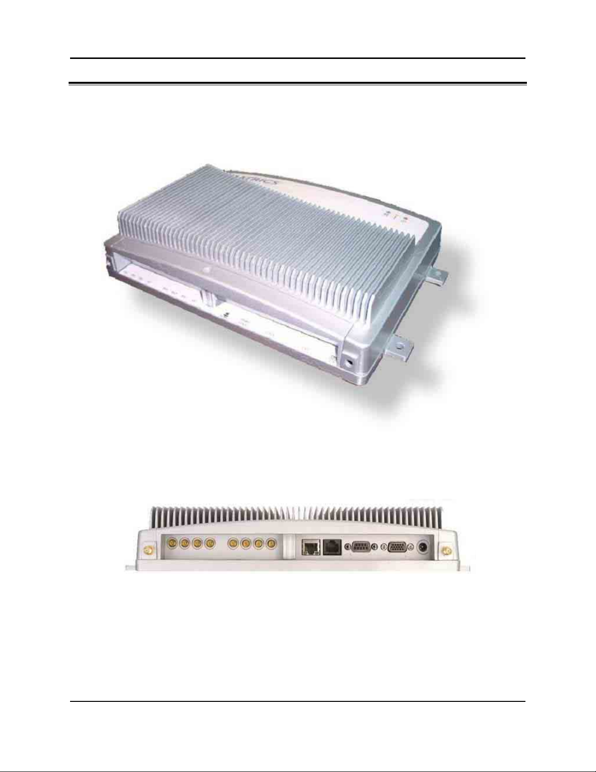
AR-400-US Reader Diagrams
Top View
Side Vie w
4 AR 400 Reader User’s Manual 2003-2004 Matrics, Inc.
Page 9
LEDs and Connectors
ITEM DESCRIPTION
RJ45 Connector 10BaseT Ethernet
DB9 Connector RS232 Console (Management)
DB15 Connector Control I/O Port (6)
RS422/R S 485 Connector Connect to host PC and bus power.
Power/Link LED LED is green when the Reader is powered on and linked to the host PC.
Error LED LE D is red when commands are incorrectly received from the host PC.
Read LED LED is yellow when com mands are correctly received from the h o st PC.
+24vDC 1.2A Co nnector
(Unit Power)
Mini-UHF Antenna Connectors Connect to external antennas (4 Transmit and 4 Receive.)
The power supply should be plugged into a wall outlet and into the DC
power connector (2.1mm jack.)
Interface Pin-Outs
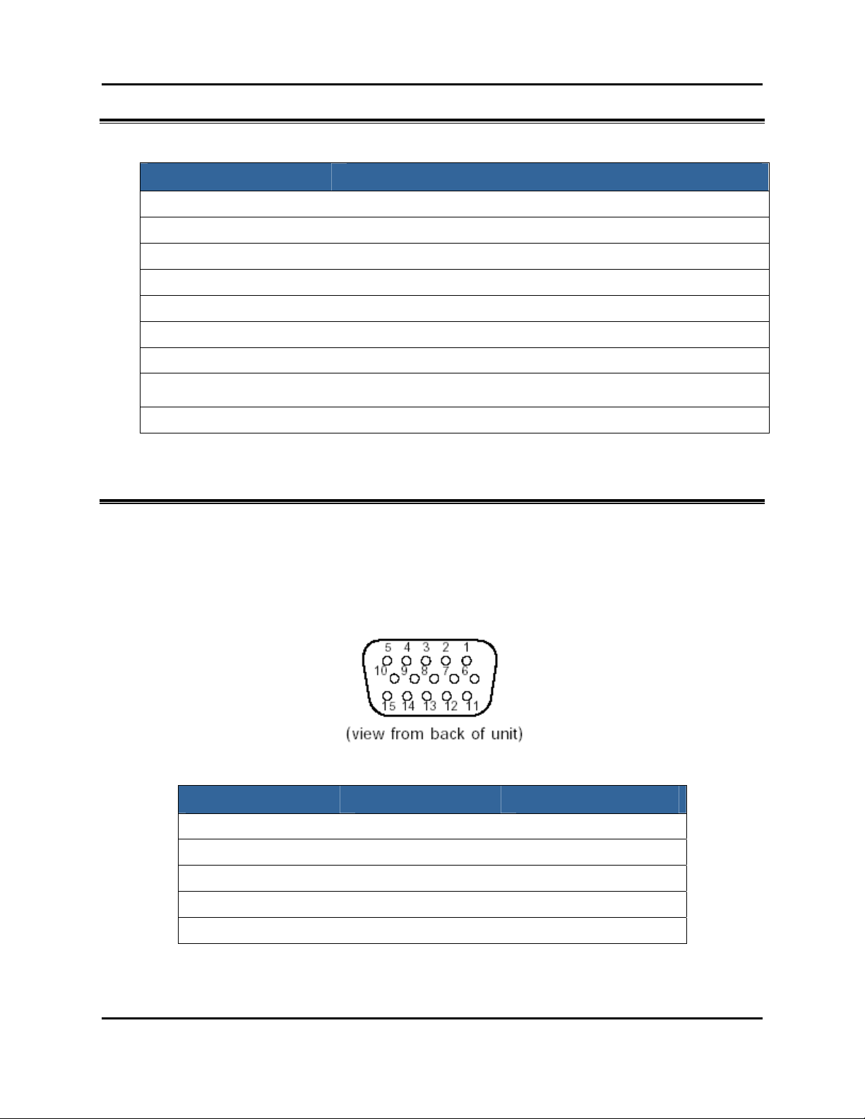
I/O Interface
15-pin Female D-sub Connector:
PIN: FUNCTION PIN: FUNCTION PIN: FUNCTION
1: Ground 6: In2 11: Out1
2: Out4 7: In 0 12: In 5
3: Out2 8: Ground 13: In3
4: Out0 9: Out5 14: In 1
5: In 4 10: Out3 15: Vcc +5V po wer supply
AR 400 Reader User’s Man ual 2003-2004 Matrics, Inc. 5
Page 10
PARAMETER MIN. TYPICAL MAX. UNIT
Inx VIL
Inx VIH 2.0
Outx VOL
Outx VOH 3.7
Outx IOL
Outx IOH
Vcc Imax
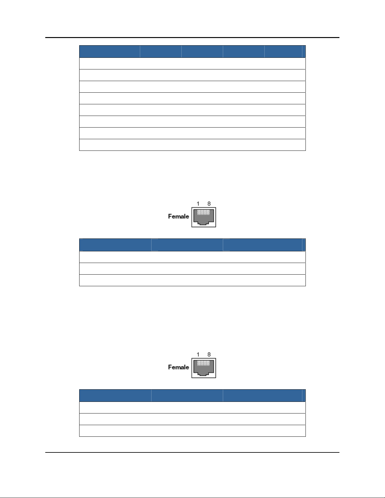
Ethernet Interface
Modular Jack RJ45:
Vcc 4.5
0.8 V
V
0.55 V
V
24 mA
-24 mA
5.5 V
100 mA
PIN: FUNCTION PIN: FUNCTION PIN: FUNCTION
1: TD+ 4: Common 7: Common
2: TD- 5: Comm on 8: Co mmon
3: RD+ 6: RD-
RS422/485 Interface
Modular Jack RJ45:
PIN: FUNCTION PIN: FUNCTION PIN: FUNCTION
1: Tx+ 4: NC 7: Rx2: Tx- 5: NC 8: Rx +
3: Ground 6: Ground
6 AR 400 Reader User’s Manual 2003-2004 Matrics, Inc.
Page 11
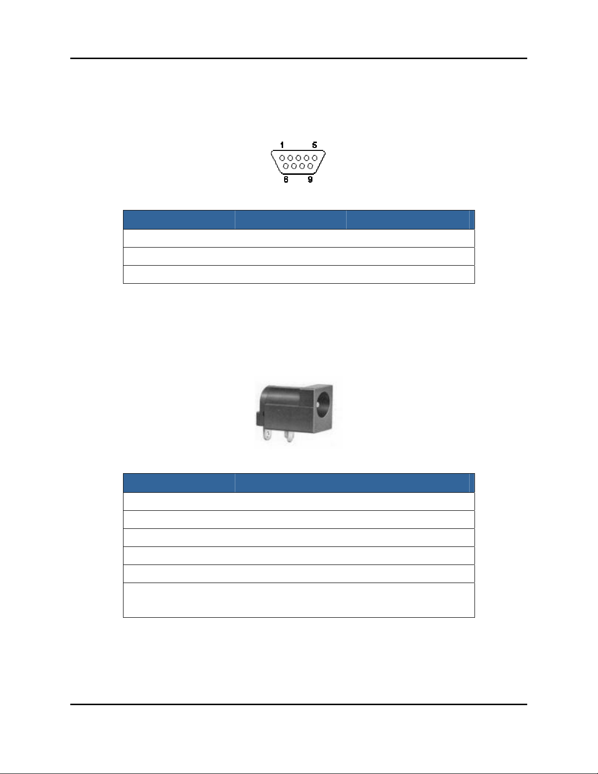
RS232 Interface
9-pin Female D-sub Connector:
PIN: FUNCTION PIN: FUNCTION PIN: FUNCTION
Power Supply
PWR JA CK 2. 1X5.5MM:
1: NC 4: NC 7: NC
2: Tx 5: Ground 8: NC
3: Rx 6: NC 9: NC
ITEM DESCRIPTION
Rating 24vDC @ 1. 2A
Contact Resistance 30m OHMS Max
Insulation R esistance 50m OHMS Min: 100vDC
Voltage W ithstand 250v AC R.M.S. for 1 minute
Life 5,000 cycles
Center Pin: Ground
Pin Assignments
Outer Pin:
Vcc Imax:
AR 400 Reader User’s Man ual 2003-2004 Matrics, Inc. 7
Page 12

PCMCIA Interface
PC Card Intern al Slot, PCMCIA header 68-pin:
PIN: FUNCTION PIN: FUNCTION PIN: FUNCTION
1: Ground 24: PA5 47: N/C
2: PD3 25: PA4 48: N/C
3: PD4 26: PA3 49: N/C
4: PD5 27: PA2 50: N/C
5: PD6 28: P A1 51: VCC
6: PD7 29: P A0 52: VPP2
7: CE1# 30: PD0 53: N/C
8: PA10 31: PD1 54: N/C
9: OE# 32: PD2 55: N/C
10: N/C 33: IOIS16# 56: N/C
11: PA9 34: Ground 57: VS2#
12: PA8 35: Ground 58: RESET
13: N/C 36: CD1# 59: WAIT#
14: N/C 37: PD11 60: I NPACK#
15: WE# 38: PD12 61: REG#
16: IR EQ# 39: PD13 62: SPKR#
17: VCC 40: PD14 63: N/C
18: VPP1 41: PD15 64: PD 8
19: N/C 42: CE2# 65: PD9
20: N/C 43: VS1# 66: PD10
21: N/C 44: IORD# 67: CD2#
22: PA7 45: IOWR# 68: Ground
23: PA6 46: N/C
8 AR 400 Reader User’s Manual 2003-2004 Matrics, Inc.
Page 13
Section 4. I n stalling th e Read er
The instructio ns prov ided in this se ctio n de scribe a gene ric installatio n of th e AR 400 R eader. Depe nding
upon your application, your installation steps may vary. Contact Matrics (refer to the “Contact Us”
section in this User’s Manual) if you need further assistance fo r a customize d installation.
Follow the steps li sted below (an d de tailed in the f ollowing sections) to instal l and test y our A R 400
Reader:
1. Check that you have all of the items you need before you proceed with your Reader installation (refer
to the “Getting Started” section below.)
2. Mount the Reader in a location chosen for optimal surveillance.
3. Conn ect a nten na(s) to the Reader.
4. Connect the Reader to your host computer.
5. Pow er on the Read er.
6. Verify that your Reader installation is operational.
Getting Started
Before you proceed with your Reader installation, check that you have all of the items you need. Contact
Matrics (refer to the “Contact Us” section in this U ser’s Manual) if any of the parts listed in this section
are missing from your Reader package, or any of the items you received are damaged.
NOTE: You should use ONLY those parts provided in your Reader
pack age or specifi cally recommended by Matr ics. Do not substitute an y
other cables, etc., since doing so may degrade your system’s performance,
damage your Reader, and void your warranty.
In addition to this User’s Manual, y ou should have received the following items in your package:
MODEL NUMBER (MN) PART NUMBER (PN) QTY. DESCRIPTION
AR-400-US 250009-001 1 AR 400 Reader
201529-001 1 24vDC Power Su pply
In addition, you will need:
• Four (4) screws for mounting the Reader, and
• Several wire ties to secure any extra lengths of cable.
AR 400 Reader User’s Man ual 2003-2004 Matrics, Inc. 9
Page 14
Mount the Reader
Before mounting the Reader, you must select a location for it. For best results, consider the following
wh en d eter min ing the o ptimal placem ent for your Reader:
Mount the Reader indoors, in operating range, and out of direct sunlight, high moisture,
or extreme temperatures.
Mount the Reader in an area free from electromagnetic interference. Such sources of
interference may include: gene rators, pumps, converters, non-interruptible power
supplies, AC switching relays, light dimmers, computer CRT terminals, etc.
Mount the Reader within 15 feet of your antennas (antenna connector cables from
Matrics are 15-feet long.)
Make sure the local power supply cord, when attached to the Reader, can reach the power
source outlet.
Do not mount the Reader within 12 inches of a computer CRT terminal.
Make sure that you will be mounting the Reader onto a permanent fixture (wall or shelf)
where it won’t get disturbed, bumped, or damaged. Keep in mind that you will need five
(5) inches of clearance on all sides of the Reader.
WARNING: The antenna must be install ed in a manner that en su res a
minimum separati on distance of 23 centimeter s betw een the antenna and
human beings.
CAUTION: If the Reader is not installed properly, it could be damaged
and your system performance diminished.
To mount the Reader:
1. Positi on the AR 400 R eader at the desired mounting position on the wall or shelf. Make sure that
there are five (5) inches of clearance on all sides of the Reader.
2. Using the pre-drilled holes at the corners of the Reader to guide you, drill four holes for mounting the
reader.
3. Securely affix the Reader to the wall of shelf using the four screws that you provided.
10 AR 400 Reader User’s Man ual 2003-2004 Matrics, Inc.
Page 15

Connect Antenna(s) to the Reader
Attach your antenna(s) to the Reader in sequential order (first connecting Antenna 1 to Reader connectors
Tx1 and Rx1, then Antenna 2 to Reader connectors Tx2 and Rx2, Antenna 3 to the Tx3/Rx3 connectors
next, and Antenna 4 to the Tx
1. Attach the large ends of your antenna connector cables to the large connectors on the antenna.
2. Attach the small ends of the cables to the corresponding connectors on the Reader (Antenna 1 to
Reader connectors Tx
3. Secure your cables using wire ties (do not bend the cables.)
WARNING: Do not disconnect antenna cables when actively reading tags
(if the LED is lit on the Reader, don’t disconnect the antenna cables.) You
could severely damage your Reader. Make sure that you unplug the power
supply to powe r off th e system first be fore disc onnecting cables.
/Rx4 connectors last.)
4
and Rx1, etc.)
1
Connect the Reader to a Host Computer
The steps you must follow to interface the Reader with your system depend upon the software package
you choose to use. Contact Matrics (refer to the “Contact Us” section in this User’s Manual) for more
information.
Power On (and Off) the Reader
1. Conn ect the provid ed 24vDC power supply to the Re ader ’s Uni t Pow er por t.
2. To power on the system, inse rt the plug end of the pow er supply into a 24v power o utlet. The gre en
Power/Link LED on the Reader should turn on, indicating that the Reader is powered on and the
system is live.
3. To power off the Rea der, unpl ug the power supply from the power outlet. The green Power/Link
LED on the Reader should turn off, indicating that the Reader is powered off and the system is not
operational.
AR 400 Reader User’s Man ual 2003-2004 Matrics, Inc. 11
Page 16

Verify the Reader Installation
Reader On?
Afte r yo u hav e in stalled the AR 400 Reader as described in this User’s Manual, test that the Reader is on
by following the instructions provide d above in the “Power o n (and Off) the Reader” section.
To verify that the Reader is operational, power it on by plugging the power supply (attached to the
Reader) into the appropriate power outlet. The green Power/Link LED on the Reader should turn on,
indicating that the Reader is powered on and the system is operational.
Test Read Range
Afte r yo u hav e in stalled the AR 400 Reader as described in this User’s Manual, test the read distance of
your hardware configuration to verify that it meets your needs.
1. To measure the read distance between the Reader and a tag, hold a tag in front of you (with the tag
face parallel to the antenna face.)
2. Walk slowly toward the antenna until the Reader responds by lighting the yellow Read LED. This
indicates that the Reader has detected and read the tag.
NOTE: For purposes of this test, we recomm end that you do not hold the
tag at an angle, or wave the tag in front of the antenna, as that may cause
the measured read distance to vary.
3. In order to read the same tag again, first remove the tag com pletely from the Reader’s read field, and
then perform Step 2 ag ain.
12 AR 400 Reader User’s Man ual 2003-2004 Matrics, Inc.
Page 17
Section 5. Configuring the Reader
Follow the steps li sted below (an d de tailed in the f ollowing sections) to con figu re your AR 400 Reader:
1. Launch and log in to the Reader Administrator Console via its Web interface.
2. Familiarize yourself with the system by using the Setup Wizard and/or Online Help.
3. Create standard Read Point configurations (via the Read Point Class and Read Point Zone pages.)
4. Perform the basic configuration of Reader Ports (via the Configuration page.)
5. Define the list of trusted hosts (via the Trusted Hosts page), and enable or disable trusted hosts
checking.
6. Set user access controls (via the Manage Users page.)
7. Commit or discard your changes (via the Commit/Revert page.)
8. Log out of the system (via the Logout link on any page.)
Launch and Log In to the Reader Administrator Console
Users must log in to the system to ensure that: 1) System access is granted only to authorized users, and
2) Only one user is logged in at a time to ensure that multiple users don’t make conflicting changes to the
system.
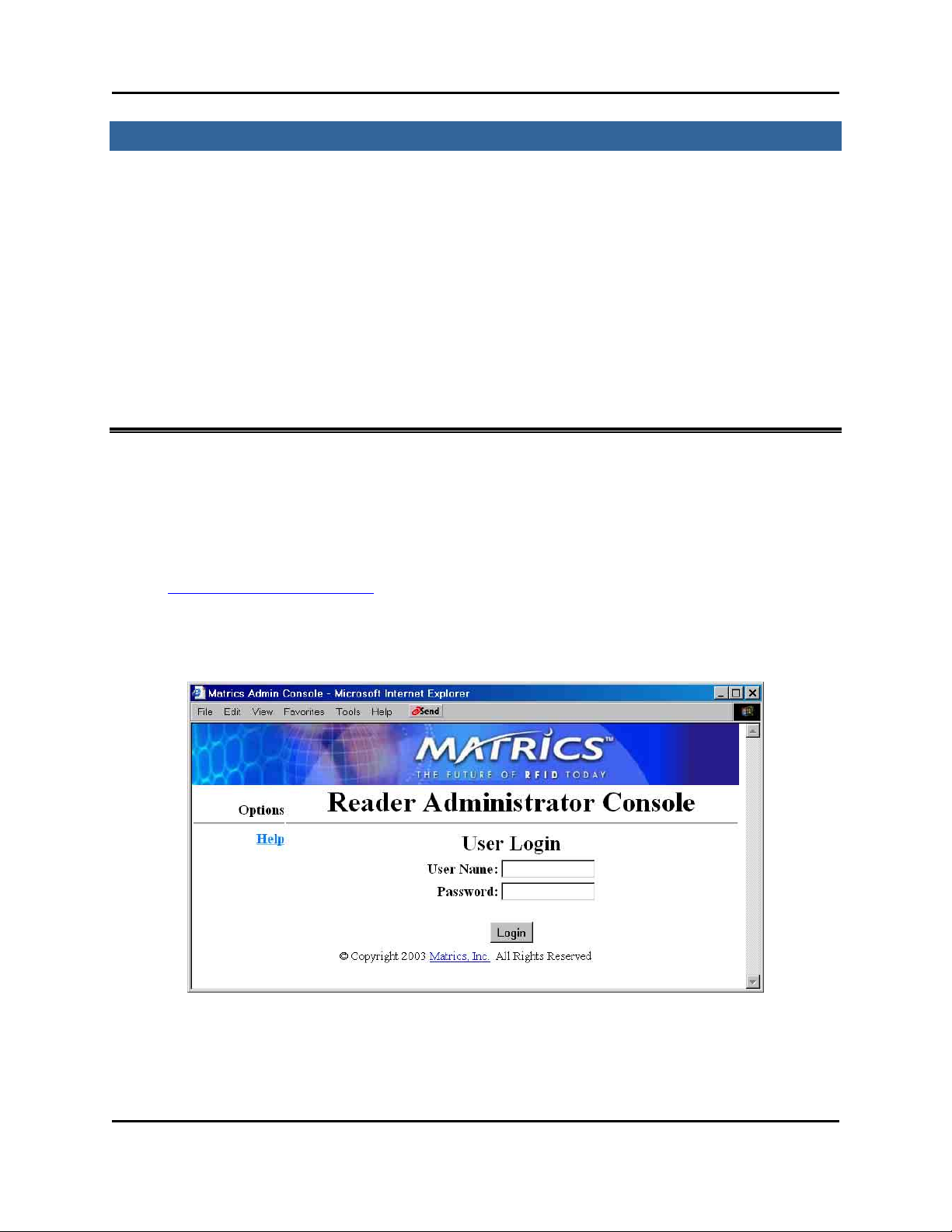
1. Using the Web browser of your choice, launch the Reader Administrator Console by typing
http://your Reader’ s IP ad dress
DHCP , the defa ult I P addr ess is 192.168.127.254.
The User Login page displays.
into the browser’s Address field. If the Reader is not defaulted to
2. If this is the first time you have logged into your system, login to the default Admin account by
typing ‘admin’ in the User Name field, ‘change’ in the Password field, and then clicking Login.
AR 400 Reader User’s Man ual 2003-2004 Matrics, Inc. 13
Page 18
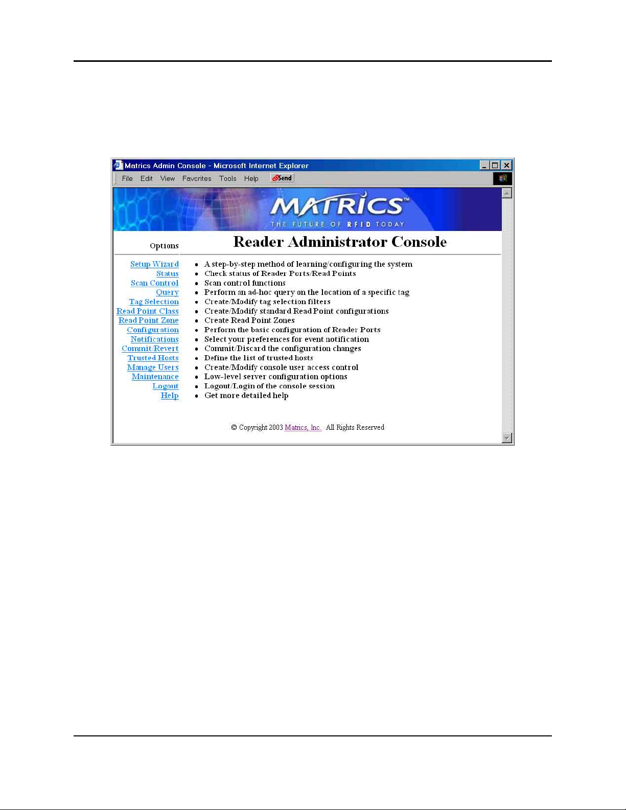
For subsequent logins, after you’ve created users (refer to the “Manage Users” section in this manual
for more information), type your user name in the User Name field, your password in the Password
field, and then click Login.
The Main page displays.
The Main page provides an informational list of Reader functions, and links to each of the Reader’s
dynamic we b pages. Click a link on the left-hand side of the Main page to display the corresponding
page.
14 AR 400 Reader User’s Man ual 2003-2004 Matrics, Inc.
Page 19
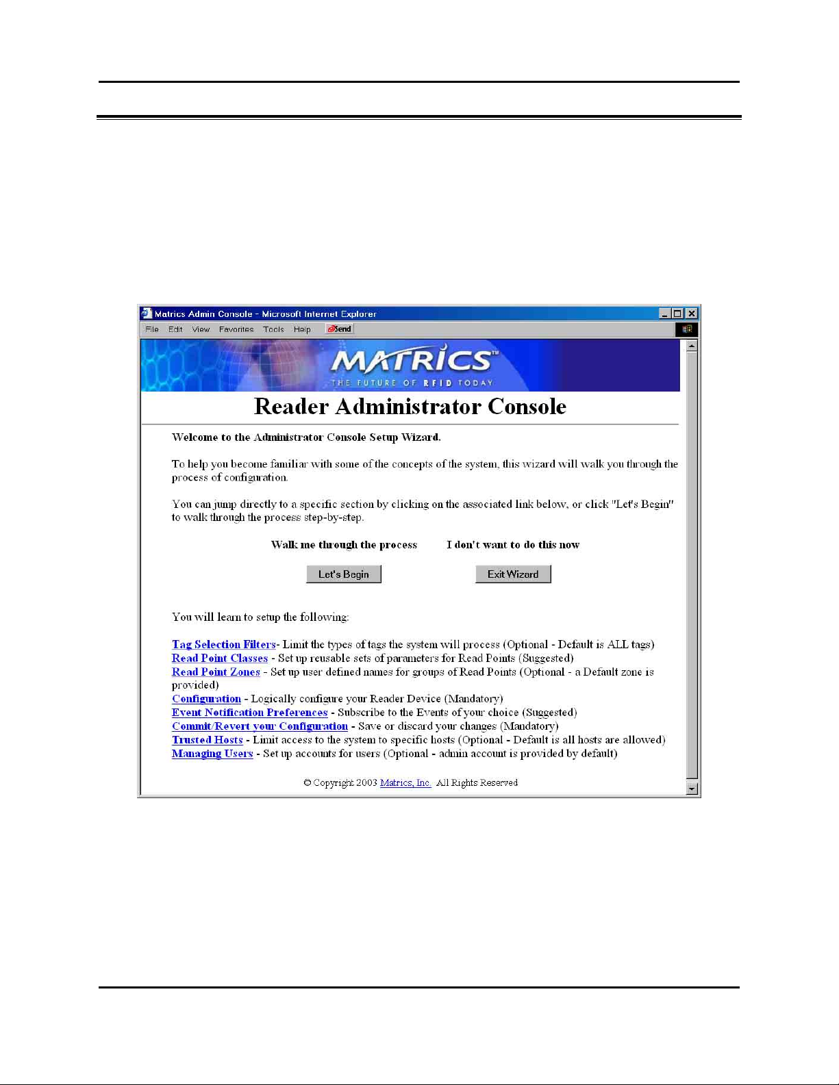
Use Setup Wizard
The Setup Wizard walks you through a test setup of the system to familiarize you with the process of
configuring a system.
1. If you haven’t already done so, launch and log in to the Reader Administrator Console.
2. Click the Setup Wizard link on the left-hand side of the main page. The Reader Administrator
Console Configuration Wizard page displays.
Click the Let's Begin button to start the Setup Wiz ard from the beginning , or click a to pic l ink a t the
bottom of the page to j ump d irectly to tha t topic . Then, simply read the pages displa ye d for you, and
click Next Step to move through the Wizard page-by-page.
AR 400 Reader User’s Man ual 2003-2004 Matrics, Inc. 15
Page 20
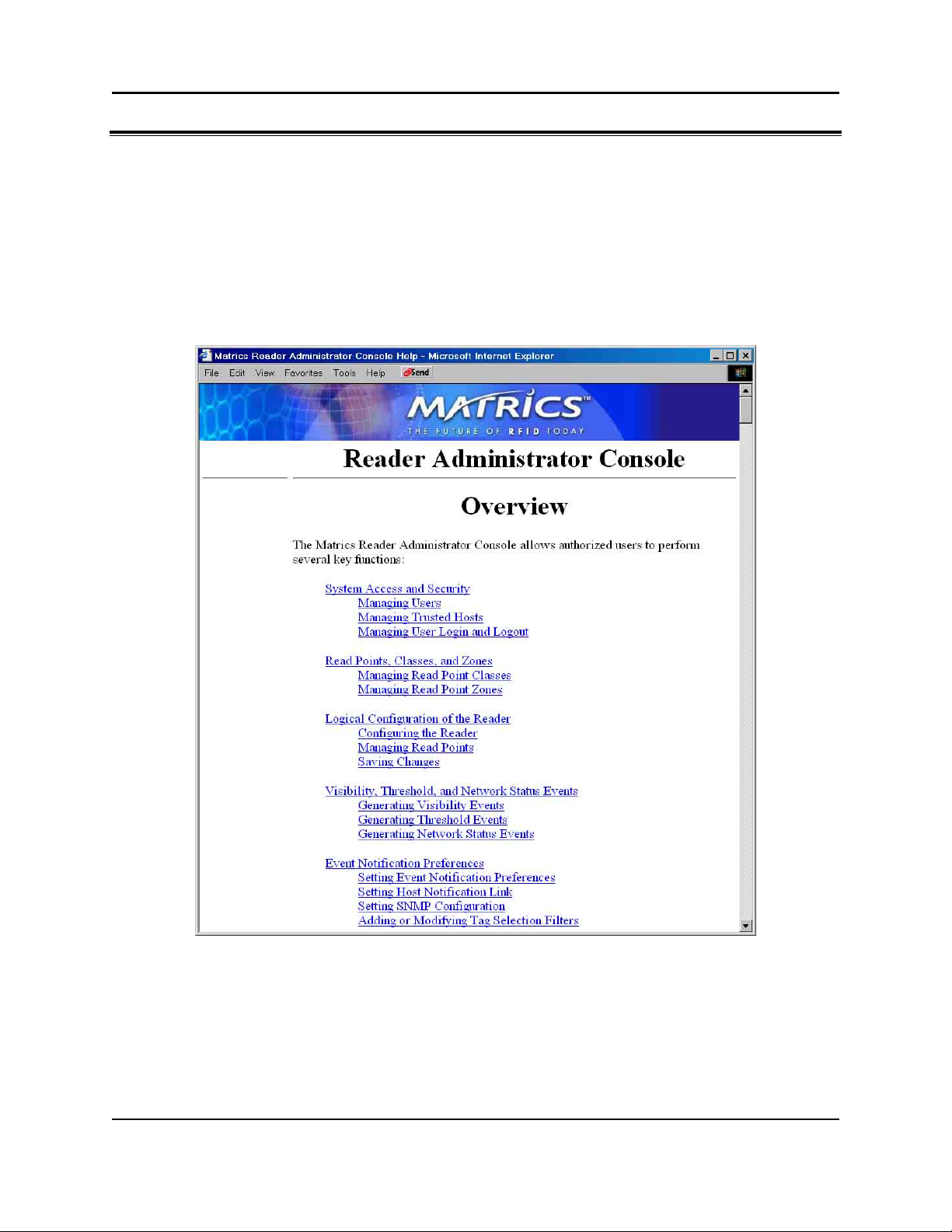
Use Online Help
The Help pages provide easy online access to conceptual and procedural information related to the
Reader Administrative and Maintenance Consoles.
1. If you haven’t already done so, launch and log in to the Reader Administrator Console.
2. To view Help for the Administrator Console, click the Help link on the left-hand side of any page in
the Administrator Console. The Administrator Console Help page displays in a separate window.
The Overview section at the top of the Help page provides a ‘table of contents’ of topic links. Click a
topic link in the Ov erview section to jump to that topic.
3. To view Help for the Maintenance Console, click the Help link on the left-hand side of any page in
the Maintenance Console. The Maintenance Console Help page displays in a separate window.
16 AR 400 Reader User’s Man ual 2003-2004 Matrics, Inc.
Page 21
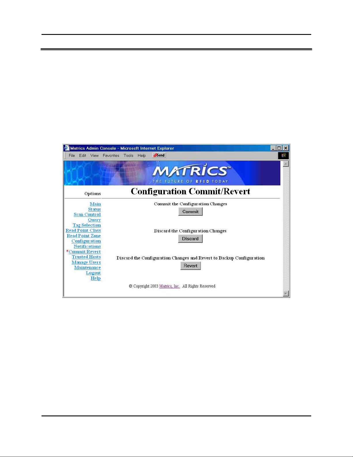
Save or Discard Changes (or Revert to Backup)
Whenever you add or make modifications to your Reader configuration using the Reader Administrator
Console, the changes are not immediately applied to the underlying physical Reader Network of hardware
components and networked connections. You must click Commit to save the changes and notify the
Reader to update its configuration file, which updates your physical Reader configuration. While a
successful update may take up to a minute to complete, your system will continue to operate with only a
brief one- or two-second period where no polling is taking place.
1. Click the Commit/Revert link on the left-hand side of any Reader Administrator Console page. The
Configuration Commit/Revert page displays.
2. Click Commit to save a new configuration, and apply changes to the Reader’s configuration file.
3. Click Discard ONLY if you decide you DO NOT want to save changes to the Reader’s configuration
file that you’ve made to the Reader configuration during this session.
4. Click Revert ONLY if you’ve saved a backup configuration, and you want to discard your current
changes AND revert your physical Reader configuration to the backup configuration.
AR 400 Reader User’s Man ual 2003-2004 Matrics, Inc. 17
Page 22
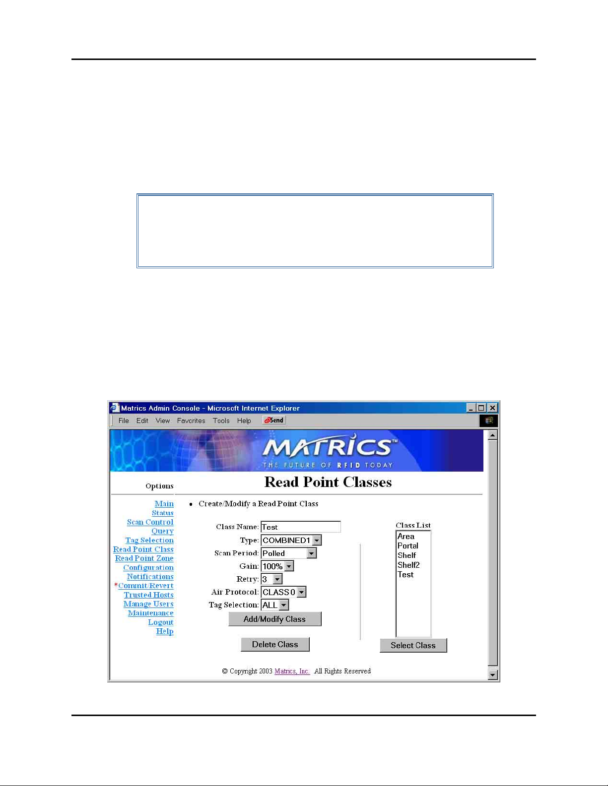
Create Read Point Classes
A read point is an individually addressable antenna. Every read point must have a read point class
associated with it, w hich is where you d efine certain parameters in an e ffort to fine tune the performance
and characte ristics of the re ad poi nt.
Multiple read points may share a single read point class. So, once you define a read point class, you can
re-use it many times without re-entering the same parameters over and over again.
You can add a new read point class from scratch (naming it and specifically setting its parameters), or
you can use an existing read point class as a template (copying its settings, and renaming it.)
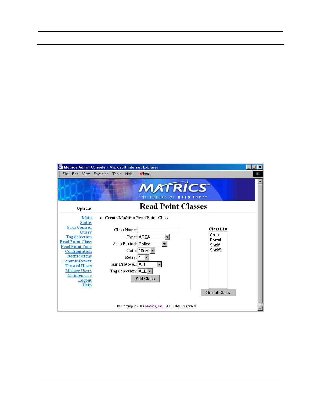
1. If you haven’t already done so, launch and log in to the Reader Administrator Console.
2. Click the Read Point Class link on the left-hand side of any page. The Read Point Classes page
displays.
3. To add a new read point class, enter the following information:
• A unique Class Name (one that does not already exist in the system),
• The antenna Type--AREA (long range), SHELFv1 (existing short range shelf type), SHELFv2
(next generation short range shelf type), COMBINED1, or COMBINED2,
• Set the S can Period to tell how often the read point is to be ch ecked for tag s,
• Set the Gain (as a percentage) to designate the antenna’s power setting,
18 AR 400 Reader User’s Man ual 2003-2004 Matrics, Inc.
Page 23
• Set Retry to tell the Read er how many times to r epea t the read com mand each time a scan is to
be performed,
• Set A ir Prot ocol to A ll, Class 0, or Class 1 to tell the Reader w hic h proto col to use to
interrogate tags, and
• Set Tag S election to designate which tags to read.
Afte r typi ng the required informatio n, clic k the Add Class button. If the data is val id, the read po int
class is added and the Class List updated.
NOTE: Your physical Reader configuration is not updated until you click
Commit [refer to the “Save or Discard Change s (o r Revert to Back up)”
section in this manual for more information.] If not successful, the system
should indicate the problem and allow you to correct it by repeating the
operation.
4. To create a new read point class by copying an existing class, select the existing class’ name in the
Class L ist, and the n cl ick the Select Class button. The values of the existing class are copied
(including the name.) Change the name of the copied class, and then click Add/Modify Cl ass. A new
read point class is created.
5. To modify a read point class, select the class’ name in the Class List, and then click the Select Class
button. The values of the class auto-populate the fields on the left-hand side of the Read Point
Classes page.
AR 400 Reader User’s Man ual 2003-2004 Matrics, Inc. 19
Page 24

Modify the parameters as needed, and then click Add/Modify Class.
NOTE: If you modify the class’ name, a new class is created. If you modify
the class’ parameters and DO NOT modify its name, then the existing class
is updated with the changes you made to its parameters.
When you modify a read point class’ parameters, all read points that are assoc iated with that class
are a utom atica lly upda ted.
6. To delete an unused read point class, select the class’ name in the Class List, click Select Class, and
then click the Delete Class button. You cannot delete default read point classes.
7. Commit or discard your changes (refer to the “Save or Discard Changes (or Revert to Backup)”
section in this manual for more information .)
20 AR 400 Reader User’s Man ual 2003-2004 Matrics, Inc.
Page 25

Create Read Point Zones
While you are not required to create or use them, read point zones allow you to group several read points
in a logical, customized manner. For example, you might create a zone named Warehouse XYZ to group
all read points installed in a particular warehouse area, or Store ABC to group all read points installed in
a particular retail location. A default zone (named ‘Default’) is provided for you.
1. If you haven’t already done so, launch and log in to the Reader Administrator Console.
2. Click the Read Point Zone link on the left-hand side of any page. The Read Point Zones page
displays.
3. To add a new read point zone, type a unique zone name (one that does not already exist in the
system), and then click the Add Zone button. The new zone name displays in the Zone List.
The new zone can now be associated with one or more read points (refer to the “Add or Modify Read
Points” section in this manual for more information.)
AR 400 Reader User’s Man ual 2003-2004 Matrics, Inc. 21
Page 26

NOTE: Your physical Reader configuration is not updated until you click
Commit [refer to the “Save or Discard Change s (o r Revert to Back up)”
section in this manual for more information.] If not successful, the system
should indicate the problem and allow you to correct it by repeating the
operation.
4. To modify a read point zone, select the zone’s name in the Zone List, and then click Select Zone.
The Zone Name field on the left-hand side of the Read Point Zone page auto-populates with the
selected zone’s name.
Change the selected zone’s name as needed, and then click Modify Zone.
5. To delete an unused read point zone, select the zone’s name in the Zone List, click Select Zone, and
then click the Delete Zone button. You cannot delete the default read point zone.
6. Commit or discard your changes (refer to the “Save or Discard Changes (or Revert to Backup)”
section in this manual for more information .)
22 AR 400 Reader User’s Man ual 2003-2004 Matrics, Inc.
Page 27

Configure the Reader
The Reader Administrator Console’s Reader Configuration pages allow you to logically describe the
ante nna connec tions of y our ph ysical Reader, so that the AR 400 Reader can co mmunicate to other
systems the connectivity and parameters of the devices.
Before you use the Reader Administrator Console to define the configuration of your Reader, you must
gather certain information about your physical devices from the personnel who installed them. For
example, you will need to know what types of devices are connected to each port and the parameters
associated with those devices. You also need to know the network configuration parameters (such as IP
addresses, netmask and default gateway, etc.)
Once you have obtained the information you need about your physical devices, you can access the
dynamic we b pages in the Reader Administrator Console, which act as a wizard to walk you through the
process of defining your Reader configuration and the association of its devices.
By default, a standard Reader configuration is displayed with a Reader link and links for four Reader
ports. A port can connect directly to a read point (antenna), or combine with a subsequent port to connect
to a splitter. The followi ng list de scribes the four possible port com binati ons:
• 4 Ports -- All four ports connec t directly to read points.
• 1 Splitter + 2 Ports -- The f irst tw o ports connec t to one spli tter, the other two connec t directly to
read points.
• 2 Ports + 1 Splitter -- The f irst tw o ports connec t directl y to r ead points, the o ther two connect to
one splitter.
• 2 Splitters - - The f irst tw o ports connect to on e spli tter, the other two connec t to ano ther splitter.
The current Reader port status (dire ct port or splitter port) determines wh at kind of read points can be
attached to this specific port. In oth er word s, it determines w hat Re ad Point Class types can be used with
this atta ched read point, essentiall y determin ing a subset o f compatible Read Point Classes with these
types.
• If a port connec ts to a re ad poi nt dir ectly, the l ink f or the read point provide s acc ess to i ts
param eter s.
• If a port i s empty, Add R eadPoint and Add Splitter links are displayed.
• If a splitter is used:
o If a r ead point has not been added yet to this spl itter, a Delete Splitter link is provided if you
want to remove the splitter, and an Add ReadPoint link is provided if you want to add a
read point to the splitter.
o If a r ead point has been added to this splitter, the onl y link provided is to access to the read
poin t’s param eter s.
AR 400 Reader User’s Man ual 2003-2004 Matrics, Inc. 23
Page 28

Modify a Reader’s Attributes
1. If you haven’t already done so, launch and log in to the Reader Administrator Console.
2. Click the Configuration link on the left-hand side of any page. The Reader Configuration page
displays.
3. To view the Reader’s attributes, click the Reader link at the top of the Reader Configuration page.
The Reader Configuration’s Modify a Reader page displays. The fields on the Modify a Reader page
auto-populate with the selected Reader’s attributes.
24 AR 400 Reader User’s Man ual 2003-2004 Matrics, Inc.
Page 29

• To customize the Reader’s name and/or descriptive information, type a unique name (one that
does not already exist in the system) and/or description to help identify the Reader (for example,
its location), in the corresponding fields. Click Modify Reader when you are done to return to
the Reader Configuration page.
• A unique (factory defined) serial number is displayed in the Serial # field in the format “nnnn-
nnnn-nnnn-nnnn.”
• Check Disable Reader on the Reader Configuration’s Modify a Reader page if you want to
disable this Reader from add and modify operations. Click Modify Reader whe n you are done to
return to the Reader Configuration page.
Add, Modify, or Delete Read Points
When you add a read point to the logical view of your Reader, you add it to a Reader port.
1. If you haven’t already done so, launch and log in to the Reader Administrator Console.
2. Click the Configuration link on the left-hand side of any page. The Reader Configuration page
displays.
3. To add a sing le read point to a particular Rea der port, c lic k Add ReadPoint. The Reader
Configuration’s Add Read Point page displays.
AR 400 Reader User’s Man ual 2003-2004 Matrics, Inc. 25
Page 30

4. To add a read point to the associated Re ader port, enter the followi ng informatio n:
• A uniqu e re ad poi nt Name (one that does not already exist in the system),
• An optional Description to help iden tify the read point (f or exa mple, its l ocation),
• The rea d point Class to associate w ith this read point, and
• The rea d point Zone to associa te w ith this read point.
• Check Disable if you want to disable this read point from add and modify operations.
5. After typing the required information, clic k the Add ReadPoint button. If the data is valid, the rea d
point is added and the updated logical view of your Reader configuration displays.
NOTE: Your physical Reader configuration is not updated until you click
Commit [refer to the “Save or Discard Change s (o r Revert to Back up)”
section in this manual for more information.] If not successful, the system
should indicate the problem and allow you to correct it by repeating the
operation.
6. To modify a read point, select it on the Reader Configuration page, and the Reader Configuration’s
Modify Read Point page displays. The fields on the Modify Read Point page auto-populate with the
selected read point’s settings.
26 AR 400 Reader User’s Man ual 2003-2004 Matrics, Inc.
Page 31

Change the selected read point’s settings as needed, and then click Modify Read Point.
7. To delete a read point, select it on the Reader Configuration page, and the Reader Configuration’s
Modify Read Point page displays. The fields on the Modify Read Point page auto-populate with the
selected read point’s settings.
Click Delete Read Point. The selected read point is removed from the logical view of your Reader
configuration.
8. Commit or discard your changes (refer to the “Save or Discard Changes (or Revert to Backup)”
section in this manual for more information .)
Add or Delete a Splitter
When you add a splitter to the logical view of your Reader, you add it to a Reader port.
1. If you haven’t already done so, launch and log in to the Reader Administrator Console.
2. Click the Configuration link on the left-hand side of any page. The Reader Configuration page
displays.
3. To add a splitter to a particular R eader port, click Add Splitter. A Delete Splitter link is provided if
you choose to remove the splitter later, and an Add ReadPoint link is provided if you want to add a
read point to the splitter.
AR 400 Reader User’s Man ual 2003-2004 Matrics, Inc. 27
Page 32

4. Click Add ReadPoint to add a read point to the splitter. The Reader Configuration’s Add Read
Point page displays.
5. To add a read point to the associated spli tter, ente r the f ollowing i nformation:
• A uniqu e re ad poi nt Name (one that does not already exist in the system),
• An optional Description to help iden tify the read point (f or exa mple, its l ocation),
• The rea d point Class to associate w ith this read point, and
• The rea d point Zone to associa te w ith this read point.
• Check Disable if you want to disable this read point from add and modify operations.
6. After typing the required information, clic k the Add ReadPoint button. If the data is valid, the rea d
point is added and the updated logical view of your Reader configuration displays.
NOTE: Your physical Reader configuration is not updated until you click
Commit [refer to the “Save or Discard Change s (o r Revert to Back up)”
section in this manual for more information.] If not successful, the system
should indicate the problem and allow you to correct it by repeating the
operation.
28 AR 400 Reader User’s Man ual 2003-2004 Matrics, Inc.
Page 33

Define Trusted Hosts
To ensure the controlled and secured access to Reader Administrator Console functions, you should
designate which computers are authorized to have system access. You do this by setting up “trusted
hosts” (authorized computers.) Only computers that are registered in the system as trusted hosts can
successfully access Reader Administrator Console functions.
1. If you haven’t already done so, launch and log in to the Reader Administrator Console.
2. Click the Trusted Hosts link on the left-hand side of any page. The Trusted Hosts page displays.
Trusted hosts checking is disabled by default (to allow your first admin to log in from anywhere.)
With trusted hosts checking disabled, the IP address of any system that accesses the Reader is
automatically added to the Current Trusted Hosts List. You can use this feature to see which systems
have accessed the Reader, thereby enabling you to track down any unauthorized users.
However, if you wish to limit Reader access to only those computers that you’ve designated in the
Current Trusted Hosts List, then you should enable trusted hosts checking for higher security.
AR 400 Reader User’s Man ual 2003-2004 Matrics, Inc. 29
Page 34

3. To enable trusted hosts checking, click the Enable Trusted Hosts Check button on the Trusted
Hosts page. When enabled, the Enable Trusted Hosts Check button toggles to a Disable Trusted
Hosts Check button. Click Disabl e Trust ed Hosts Check to turn off trusted hosts checking.
4. To add a trusted host, type the computer’s IP address in the dotted notation form (0.0.0.0), not
hostn ame , in the IP Address field on the Trusted Hosts page. After you have entered the IP address,
click the Add Host button .
The system will attempt to validate the IP address by “pinging” it. If the address is properly
formatted and can be pinged, it is added to the Current Trusted Hosts List.
5. To delete a trusted host, select the computer’s IP address in the Current Trusted Hosts List on the
Trusted Hosts page, and then click the Delete Host button. The loc al ho st (127.0.0.1) cannot be
deleted.
6. Commit or discard your changes (refer to the “Save or Discard Changes (or Revert to Backup)”
section in this manual for more information .)
30 AR 400 Reader User’s Man ual 2003-2004 Matrics, Inc.
Page 35

Manage Users
To ensure the controlled and secured access to Reader Console functions, you should designate which
users are authorized to have system access, and what level of access they are allowed. You do this by
setting up authorized user accounts. Only users logging in with a registered user name and password can
successfully access Reader Console functions.
1. If you haven’t already done so, launch and log in to the Reader Administrator Console.
2. Click the Manage Users link on the left-hand side of any page. The Manage Users page displays.
3. To add a new user, type a valid User Name and Password for him or her on the Manage Users page.
A valid user name must be unique (no other user can be assigned the identical user name), and both
user name and password must consist of at least one but not more than 32 alphanumeric characters.
Also, user name and password are case-sensitive (for example, a password that is assigned to a user
typed in all lower-case letters must be entered by the user at log-in in all lower-case letters.)
AR 400 Reader User’s Man ual 2003-2004 Matrics, Inc. 31
Page 36

4. Select an access level for the new user from the Access Level drop-down list box.
The Maintenance option gives the new user all privileges (including upgrading firmware.) The Edit
optio n all ows the new user to ch ange system par ame ters, but not as extensively as Mainten ance
access. The View option allows the new user to see system settings, but not change them.
NOTE: You will only see the Maintenance optio n in the Access Level
drop-down list box if you have been granted Maintenance level access. If
you have Edit level access, for example, you will only be able to create
users with the same (Edit) or lesser level access (View) than you have.
5. Click the Add User button. If successful, the new user name displays in the User List. If not
successful, the system should indicate the problem and allow you to correct it by repeating the
operation.
6. To delete an existing user, select the user name in the User List, select the Delete User radio button,
and then click Modify User. When you delete a user, you remove him or her from the system
entirely. After a user has been deleted, a new user may be added using the old user name again.
Reset (Clear) a Password
1. To reset a user’s password (in the event he or she has forgotten it), select the user name in the User
List, and then select the Clear Password radio button.
2. Click Modify User. The user’s password is re-set automatically to the default password, “change.”
When the user attempts to log in next, the Reader will display the Change User Password page to
prompt the user to change his or her password from the default.
Change a Password
1. To change a user’s password, select the user name in the User List, select the Change Password
radio button, and then click Modify User. The Change User Password page displays.
32 AR 400 Reader User’s Man ual 2003-2004 Matrics, Inc.
Page 37

2. Type the Old Password, and the New Password (twice) on the Change User Password page, and
then click Change.
3. Commit or discard your changes (refer to the “Save or Discard Changes (or Revert to Backup)”
section in this manual for more information .)
Change an Access Level
To change a user’s access level, select the user name in the User List, and then select one of the following
radio buttons: Set to View Only Access, Set to Edit Access, or Set to Maintenance Access. Then click
Modify User.
NOTE: You cannot increase another user’s access level higher than your
own. If you have Edit level access, for example, you cannot increase another
user’s access level to Maintenance. Also, if you only have View access, you
cannot change another user’s access level at all.
Display Current Active Session Information
At the bottom of th e Man age Users pa ge, the Current Active Session Information section displays
information about your current login session, such as: your login name and access level, the IP address of
the computer from which you are accessing the system, and the date and time that you logged in.
AR 400 Reader User’s Man ual 2003-2004 Matrics, Inc. 33
Page 38

Log Out of the System
After you have configured your new system and committed your configuration to save it, you can log out
of the system. Logging out ensures the security and integrity of your system, denying unauthorized users
access to the Reader.
NOTE: If you do not log out, and you haven’t used the system for a pre-set
amount of time, the Reader logs you out of the system automatically.
1. Click the Logout link on the left-hand side of any page.
If you have any unsaved changes, the Reader will prompt you to commit or discard them.
2. If prompted to do so, commit or discard your changes (refer to the “Save or Discard Changes (or
Revert to Bac kup)” section in this manual for more information.)
34 AR 400 Reader User’s Man ual 2003-2004 Matrics, Inc.
Page 39

Your session ends, and the User Login page displays.
AR 400 Reader User’s Man ual 2003-2004 Matrics, Inc. 35
Page 40

Section 6. Noti fication of Events
Events Overview
The AR 400 Reader gen erates several type s of events: Visibility and Threshold Events th at repo rt tag
acti vity; and Network Status and Exception Ev ents th at repo rt device/sy stem a ctiv ity. If you want to be
notified when particular events occur, you can choose (subscribe to) these events via the Event
Notifications page. You may also choose whether or not you want to receive any event notifications at all.
Visibility Events
There are three types of Visibility Events that are generated when changes in tag visibility occur:
• New Tag Event — A New Tag Event is a special case event generated to notify you when a new tag
appears for the first time. A new tag is one that has never been seen before, and has not previously
been known to the Reader. You can then commission the tag (or associate an User ID and a threshold
rule to the tag.)
This event should be processed in a timely fashion to give meaningful results, so set the Notify
option to Immediate (the default for this event type). If you don’t want to be notified when this type
of event occurs, set the Notify option to Never, in which case the event is promoted to a generic
Visibility Changed Event.
• Tag Not Visible Event—A Tag Not Visible Event is a special case event generated to notify you
when a tag is not currently visible to any Read Point. For example, if a tagged item is removed from
a shelf and is out of RF range (not being seen by any Read Point), then a Tag Not Visible Event
would apply. The Event reports where the tag was located when last visible to the system.
Since there may be cases, in the normal course of operation, that a tag has transient periods when it is
changing visibility in the system, set the Notify option to Moderated to smooth out temporary
conditions, and generate an event only when the tag is no longer being actively tracked. (The AR 400
Reader still knows about the tag, but it is not visible to any Read Point.) If you don’t want to be
notified when this type of event occurs, set the Notify option to Never, in which case the event is
promoted to a generic Visibility Changed Event.
• Visibility Changed Event—A Visibility Changed Event is a generic event (not as specific as a New
Tag or Tag Not Visible Event) generated any time that the visibility of a tag changes. The visibility
change may be due to more, less, different, or even no Read Points being associated with a tag. For
example, if a tagged item moves from a shelf on aisle 2 to another shelf on aisle 4 (visibility changes
from one Read Point to another), then a Visibility Changed Event would apply.
Note: If you have enabled Tag Not Visible Events, then a tag not currently visible to any Read
Point(s) will generate the more specific Tag Not Visible Event instead. Likewise, a New Tag Event
will be generated for the first visibility change when applicable.
36 AR 400 Reader User’s Man ual 2003-2004 Matrics, Inc.
Page 41

This event should be processed in a timely fashion to give meaningful results, so set the Notify
optio n to I mmediate (the default for this even t type .)
Threshold Events
A Threshold Event is generated when the number of visible tags drops below or rises above a threshold
that you specify via a Tag List notification reply. Before you can generate Thresholds Events, you must
import and associate rules for your thresholds. Since some users may not want to set up rules and
thresholds, by default, this event’s notify option is set to Never. Threshold events are only generated
when the notify option is enabled, and User IDs and thresholds have been supplied via a Tag List. Since
there may be cases, in the normal course of operation, that a tag may have transient periods when it is
changing visibility in the system, set the Notify option to Moderated to smooth out temporary conditions,
and generate an event only when the tag is not experiencing a temporary moment of invisibility.
Network Status Events
Network Status Events alert you to changes in status of the managed resources of the Reader. For
example, if a Reader problem is detected, an event is generated by the Reader and sent without a server
request.
If you want to receive Network Status Event notifications, you must subscribe to them by setting the
SNMP configuration on the Event Notifications page. If the SNMP host is not set (or is not valid), no
Network Status Events will be sent
Network Status Events are divided into two categories, ‘device’ and ‘program.’ A Device Event notes the
change in a device’s status. A Device Event is further divided into two categories, ‘user’ and ‘system.’
Both categories have an addition specification as to whether the status change is being reported for itself
or in association with a ‘parent’ device.
For example, if the ‘user’ disabled a Reader, several events would be generated. The Reader would get a
‘user/disable’ status notification. The Read Point(s) below the Reader would get a ‘user/disable/parent’
notification. If the system detected a problem with the Reader, it would automatically disable the device,
and the matching events would be generated. These classifications allow you to not only see the overall
effect on the Reader Network, but also allow the likely offending component to be identified. When the
fault is fixed, you can ‘enable’ the device. Any device below it that was ‘parent disabled’ is automatically
brought back online.
Exception Events
Exception Events provide the same type of information available via SNMP, except over XML. An
Exception Event gives you information when a device goes off-line, polling is turned off, etc.. You may
choose this option if you don’t support SNMP, but still want to receive feedback if the device/program
changes state. XML is enabled by setting the Notify option for Exception Events to ‘Immediate’ in the
Notify column on the Event Notifications page.
AR 400 Reader User’s Man ual 2003-2004 Matrics, Inc. 37
Page 42

Set Event Notification Preferences
1. If you haven’t already done so, launch and log in to the Reader Administrator Console.
2. Click the Notifications link on the left-hand side of any page. The Event Notifications page displays.
3. To specify the event notifications that you want to receive, click the link in the Notify column
corresponding to each event type, and then select the appropriate Notify Option for the event:
• Never—The system never generates notifications for this event type.
• Immediate—The system generates notifications for this event type as soon as they are detected,
assuming they are not ‘filtered’ out.
• Moderated—The system retests this condition every minute up to the timeout value. If the
condition still exists and an intervening event has not happened since, the system generates
notifications for this event type, assuming they are not ‘filtered’ out.
Click Set Notify Option. The Event Notifications page displays again.
38 AR 400 Reader User’s Man ual 2003-2004 Matrics, Inc.
Page 43

4. To specify the event filter option that you want to use, click the link in the Filter By column
corresponding to each event type (not available for Threshold or Exception Events because they
provide system-wide information), and then select the appropriate Filter Option for the event:
• None - No filter. Allows all events to pass through.
• Zone Inclusive - Only allow events that occur in a specific Read Point Zone to pass through.
• Class Incl usive - Only allow e vents that occur in a specific Read Point Class to pass through.
• Read Point Inclusive - Only allow events that occur in a specific Read Point to pass through.
• Zone Exclusive - Only allow events that do NOT occur in a specific Read Point Zone to pass
through.
• Class Excl usive - Only allow events that do NOT occur in a specific Read Point Class to pass
through.
• Read Point Exclusive - Only allow events that do NOT occur in a specific Read Point to pass
through.
Click Set Filter Option. The Event Notifications page displays again.
5. Commit or discard your changes (refer to the “Save or Discard Changes (or Revert to Backup)”
section in this manual for more information .)
Set Host Notification Link
If the Host Notification Link is not set (or is not valid), no notifications will be sent. If you want to
receive event notifications, you must supply a valid link in the Host Notification Link field on the Event
Notifications page, and then click Set Host Link.
Set SNMP Configura tion
If the SNMP host is not set (or is not valid), no Network Status Events will be sent. If you want to receive
Network Status Event notifications, you must subscribe to them by setting the SNMP configuration on
the Event Notifications page.
1. If you haven’t already done so, launch and log in to the Reader Administrator Console.
2. Click the Notifications link on the left-hand side of any page. The Event Notifications page displays.
3. Type a valid link (a static IP address) in the Send SNMP Trap To: field.
4. Type the SNMP variable (the default value is “public”) in the SNMP Community String field.
5. Click the radio button corresponding to the version of SNMP you are using.
6. Click and check the Send Server Heartbeat checkbox if you want to receive a “positive” feedback
letting you know that the Reader is up and running. The system could detect it has gone offline (i.e.,
lost power) if it doesn’t see a heartbeat within two minutes.
7. Click Set SNMP Configuration.
AR 400 Reader User’s Man ual 2003-2004 Matrics, Inc. 39
Page 44

Section 7. Tag Selection Filters
By creating tag selection filters (and associating rules to those filters), you can specify tag selection
cri teria that y ou want th e AR 400 R eader to use to limit the tags on which it reports.
Add, Modify, or Delete Tag Selection Filters
1. If you haven’t already done so, launch and log in to the Reader Administrator Console.
2. Click the Tag Sele ction link on the left-hand side of any page. The Tag Selection Filter page
displays.
40 AR 400 Reader User’s Man ual 2003-2004 Matrics, Inc.
Page 45

3. To create a new fi lter, type a new n ame in th e Name field, and then click Create a New Filter. The
Tag Filter page displays.
4. Select a rule from the Available Rules list, and then click the << button to associate the selected rule
to the new filter. The selected rule displays in the Selected Rules list.
5. Click Add/Modify Tag Filter. The newly created filter displays in the Tag Filter List on the left-
hand side of the Tag Selection Filter page.
6. To modify a filter, select it in the Tag Filter List on the left-hand side of the Tag Selection Filter
page, and then click Select F ilter. The Tag Filter page displays. Change the selected filter’s
associated rules as needed using the << and >> buttons, and then click Add/Modify Tag Filter.
7. To delete a filter, select it in the Tag Filter List on the left-hand side of the Tag Selection Filter page,
and then click Select Filter. The Tag Selection Filter page displays. Click Delete Tag Filter. The
selected filter is removed from the Tag Filter List on the left-hand side of the Tag Selection Filter
page.
NOTE: Only filters not being used at any read point can be deleted.
AR 400 Reader User’s Man ual 2003-2004 Matrics, Inc. 41
Page 46

Add, Modify, or Delete Tag Filter Rules
1. If you haven’t already done so, launch and log in to the Reader Administrator Console.
2. Click the Tag Sele ction link on the left-hand side of any page. The Tag Selection Filter page
displays.
3. To create a new tag filter rule, select a tag format to filter and a tag type from the corresponding
drop-down list boxes on the bottom right-hand side of the Tag Selection Filter page, and then click
Create a New Rule.
42 AR 400 Reader User’s Man ual 2003-2004 Matrics, Inc.
Page 47

4. If you select “Matrics” in the Format field and “mask” in the Type field on the bottom right-hand
side of the Tag Selection Filter page, the following Tag Filter Rule page displays.
• Type a name for the new rule i n the Filter Rule Name field.
• Select Inclusive (include all tags that match this rule) or Exclusive (exc lude all tags that match
this rule) in the Test Method drop-down list box.
• Click the ra dio buttons associ ated with each numbe red bit position for its specif ic bi t mask
choice.
Note: If specifying 0 or 1 does not matter for a particular bit, simply click the x radio button for
that bit.
• Click Add Tag Filter Rule when you are done to create the new tag filter rule.
The newly created tag filter rule displays in the Tag Filter Rule List on the right-hand side of the Tag
Selection Filter page.
AR 400 Reader User’s Man ual 2003-2004 Matrics, Inc. 43
Page 48

5. If you select “Matrics” in the Format field and “field” in the Type field on the bottom right-hand
side of the Tag Selection Filter page, the following Tag Filter Rule page displays.
• Type a name for the new rule i n the Filter Rule Name field.
• Select Inclusive (include all tags that match this rule) or Exclusive (exc lude all tags that match
this rule) in the Test Method drop-down list box.
• Select a tag category in the Tag Category drop-down list box.
• Using th e hex values associated with Matrics EPC tags, type th e value for the extra 6 bits in the
EPC 96 bi t header in the EPC 96bit Header field, the Matrics Tag Type/EPC Manager value in
the Matri cs Tag Type/EPC Manager field, the EPC Object Class value in the EPC Object
Class field, and the serial number in the Serial Num ber field.
• Click Add Tag Filter Rule when you are done to create the new tag filter rule.
The newly created tag filter rule displays in the Tag Filter Rule List on the right-hand side of the Tag
Selection Filter page.
44 AR 400 Reader User’s Man ual 2003-2004 Matrics, Inc.
Page 49

6. If you select “Matrics” in the Format field and “range” in the Type field on the bottom right-hand
side of the Tag Selection Filter page, the following Tag Filter Rule page displays.
• Type a name for the new rule i n the Filter Rule Name field.
• Select Inclusive (include all tags that match this rule) or Exclusive (exc lude all tags that match
this rule) in the Test Method drop-down list box.
• Select a tag category in the Tag Category drop-down list box.
• Using the hex values associated with Matrics EPC tags, type both low range and high range
values for the valu e for the extra 6 bits in the EPC 96 bit he ader in the EPC 96bit Header
fields, the Matrics Tag Type/EPC Manager value in the Matrics Tag T ype/EPC Manager
fields, the EPC Object Class value in the EPC Object Class fields, and the serial number in the
Serial Number fields.
• Click Add Tag Filter Rule when you are done to create the new tag filter rule.
The newly created tag filter rule displays in the Tag Filter Rule List on the right-hand side of the Tag
Selection Filter page.
AR 400 Reader User’s Man ual 2003-2004 Matrics, Inc. 45
Page 50

7. If you choose an “EPC” selection in the Format field and “mask” in the Type field on the bottom
right-hand side of the Tag Selection Filter page, the following Tag Filter Rule page displays.
• Type a name for the new rule i n the Filter Rule Name field.
• Select Inclusive (include all tags that match this rule) or Exclusive (exc lude all tags that match
this rule) in the Test Method drop-down list box.
• Click the ra dio buttons associ ated with each numbe red bit position for its specif ic bi t mask
choice.
Note: If specifying 0 or 1 does not matter for a particular bit, simply click the x radio button for
that bit.
• Click Add Tag Filter Rule when you are done to create the new tag filter rule.
The newly created tag filter rule displays in the Tag Filter Rule List on the right-hand side of the Tag
Selection Filter page.
46 AR 400 Reader User’s Man ual 2003-2004 Matrics, Inc.
Page 51

8. If you choose an “EPC” selection in the Format field and “field” in the Type field on the bottom
right-hand side of the Tag Selection Filter page, the following Tag Filter Rule page displays.
• Type a name for the new rule i n the Filter Rule Name field.
• Select Inclusive (include all tags that match this rule) or Exclusive (exc lude all tags that match
this rule) in the Test Method drop-down list box.
• Select a tag category in the Tag Category drop-down list box.
• Using th e hex values associated with Matrics EPC tags, type th e value for the extra 6 bits in the
EPC 96 bi t header in the EPC 96bit Header field, the Matrics Tag Type/EPC Manager value in
the Matri cs Tag Type/EPC Manager field, the EPC Object Class value in the EPC Object
Class field, and the serial number in the Serial Num ber field.
• Click Add Tag Filter Rule when you are done to create the new tag filter rule.
The newly created tag filter rule displays in the Tag Filter Rule List on the right-hand side of the Tag
Selection Filter page.
AR 400 Reader User’s Man ual 2003-2004 Matrics, Inc. 47
Page 52

9. If you choose an “EPC” selection in the Format field and “range” in the Type field o n the bottom
right-hand side of the Tag Selection Filter page, the following Tag Filter Rule page displays.
• Type a name for the new rule i n the Filter Rule Name field.
• Select Inclusive (include all tags that match this rule) or Exclusive (exc lude all tags that match
this rule) in the Test Method drop-down list box.
• Select a tag category in the Tag Category drop-down list box.
• Using the hex values associated with Matrics EPC tags, type both low range and high range
values for the valu e for the extra 6 bits in the EPC 96 bit he ader in the EPC 96bit Header
fields, the Matrics Tag Type/EPC Manager value in the Matrics Tag T ype/EPC Manager
fields, the EPC Object Class value in the EPC Object Class fields, and the serial number in the
Serial Number fields.
• Click Add Tag Filter Rule when you are done to create the new tag filter rule.
The newly created tag filter rule displays in the Tag Filter Rule List on the right-hand side of the Tag
Selection Filter page.
48 AR 400 Reader User’s Man ual 2003-2004 Matrics, Inc.
Page 53

10. To modify a tag filter rule, select it in the Tag Filter Rule List on the right-hand side of the Tag
Selection Filter page, and then click Select Rul e. The corresponding Tag Filter Rule page displays
with the fields auto-populated with the selected rule’s settings. Change the selected rule’s settings as
needed, and then click Add/Modify Tag Rule.
11. To delete a tag filter rule, select it in the Tag Filter Rule List on the right-hand side of the Tag
Selection Filter page, and then click Select Rul e. The corresponding Tag Filter Rule page displays
with the fields auto-populated with the selected rule’s settings. Click Delete Tag Rule. The selected
tag filter rule is removed.
NOTE: Only tag filter rules not associated with a filter can be deleted.
AR 400 Reader User’s Man ual 2003-2004 Matrics, Inc. 49
Page 54

Section 8. Read er Server Cont rols
While most of the Reader Administrative Console functions allow you to create a logical view of your
Reader, the Reader Server Status and Scan Control pages give you a view of (and control over) the actual
“running” system configuration.
Check Status of Reader
The AR 400 Reader mon itors th e health and welfare of Re ader s and associated devices. Under normal
circumstances, the table displayed on the Reader Status page should show the same number of devices in
the Total column and the Enabled column. However, if devices are off-line (not enabled), you will see a
non-zero number in some of the other columns.
1. If you haven’t already done so, launch and log in to the Reader Administrator Console.
2. Click the Status link on the left-hand side of any page. The Reader Status page displays.
If you have disabled a device, you will see an entry in the User Disabled column. User-disabled
devices can be enabled via the Reader Configuration page. If there are child devices (lower in the
hierarchy) such as Read Points connected to a Reader that you have disabled, a value displays in the
Parent Disabled column.
50 AR 400 Reader User’s Man ual 2003-2004 Matrics, Inc.
Page 55

During the operation of the system, if a device becomes non-operational, the system will disable it
automaticall y, but allow the rest of th e sy stem to continue to opera te. If this happens, a SN MP trap is
generated, the appropriate device or devices are marked as system-disabled, child devices are marked
as parent-disabled, and a non-zero entry (link) displays in the System Disabled column.
For devices with multiple read points (such as a shelf), a read point can become non-operational (its
status changing to “degraded”) while its other read points continue to operate. An additional value
displays in the Enabled column for a degraded device. For example, if four read points were enabled
and one of them became d egra ded , “4/1” would displa y in the Enabl ed column. The “1” links to a list
of degraded devices, allowing you to enable degraded devices like you would a system-disabled
device.
3. To attempt to re-enable a system- disabl ed d evi ce, click the l ink in the System Disabl ed column, and
the associated Enable Device page displays. Select a device to enable and then click Enabl e Devic e,
or click Enable All Devices to attempt to enable all devices. If the device(s) is successfully brought
back into service, it will automatically enable all of the parent-disabled children, and it will be
removed from the Disabled lists.
4. If you want to auto matically attempt to re-enable degraded or sy stem- disabl ed d evice s after a
specified number of minutes, type the number of minutes in the Automatic En abl e Period field on
the Reader Status page, and then click Set Auto Enable Peri od.
5. Information displayed in the System Clock field tells you the time on the Reader. When tags are seen
and/or events a re generated, they a re time-stampe d with this time value. To chang e the time, click the
link. The System Time Management page displays. Select the appropriate values from the Year,
Month, Day, Hour, Minute, and Second drop-down list boxes, and then click Set Date and Time.
6. Information displayed in the System Up Time field tells you how long it has been running since the
system was last r eboo ted. The System Up Time field value is reset automatically each time the
Reader is rebooted.
AR 400 Reader User’s Man ual 2003-2004 Matrics, Inc. 51
Page 56

7. Information displayed in the Memory Usage and Flash Usage fields shows you the total number of
memory and flash space, and divides the space into how much is currently used and how much is
free.
Scan Control
1. If you haven’t already done so, launch and log in to the Reader Administrator Console.
2. Click the Scan Control link on the left-hand side of any page. The Reader Scan Control page
displays.
3. To initiate a scan for all On Demand read poin ts associ ated with a Read Point Class that has selected
the “On Demand” Scan Period, click Initiate Scan on the Reader Scan Control page.
The Reader queues the On Demand scans.
4. To poll read points associate d with a Read Point Class that has selec ted th e “Pol led ” Scan Period,
click Enable Polling on the Reader Scan Control page (the button toggles to Disable Polling.) To
stop polling, click Disable Polling (the button toggles back to Enable Polling.)
The polling state is saved in the configuration file when com m itted, so the system will come up with
the last saved setting.
The bottom of the Rea der S can C ontro l page displays the next per iodic scan time ( i.e., “Per iodic
Scan schedule in 3 minutes” or “There are no periodic scans scheduled.”)
52 AR 400 Reader User’s Man ual 2003-2004 Matrics, Inc.
Page 57

Section 9. Ad-h o c Queries
Whi le th e AR 400 R eader is not designed to be your prim ary source fo r quer ying tags, you can use the
Tag Query page to perf orm simpl e queries to lo cate a spec ific tag.
Perform an Ad-hoc Query for a Specific Tag
To query for a specific Matrics tag, type the tag type and ID in the corresponding Matrics Method fields
on th e Tag Query page. To query for a specific EPC tag, select the tag type, and type the hex values f or
the 96bit type, Manage r, Object Cl ass, and Serial Number (I D) in the corresponding EPC Method fields
on the Tag Query page.
Note: The Matrics Method will work for any tag type.
One of the following statements will result:
• The tag is not known to the system. (The tag has never been seen or imported.)
• The tag is not visible to the system. (The tag is known to the system, but is currently not visible to
any read point.)
• The tag i s visible at one or more read points. (A li st of re ad poi nts where the tag ca n be seen
displays.)
AR 400 Reader User’s Man ual 2003-2004 Matrics, Inc. 53
Page 58

Section 10. Maintaining the Reader
The Reader Maintenance Console allows you to view information that may be helpful to you in
maintaining a healthy Reader.
Access the Reader Maintenance Console
1. If you haven’t already done so, launch and log in to the Reader Administrator Console.
2. Click the Maintenance link on the left-hand side of any page. The Reader Maintenance Console
Main page displays.
The Reader Maintenance Console Main page provides an informational list of Reader maintenance
functions, and links to each of the Maintenance Console’s dynamic web pages. Click a link on the
left-hand side of the Main page to display the corresponding page.
The Main link returns you to the Reader Administrator Console.
54 AR 400 Reader User’s Man ual 2003-2004 Matrics, Inc.
Page 59

Manage Communicatio n Configuration Sett ings
The AR 400 Reader supports RS232 and R S485 seri al communi cation protoco ls, or TCP/IP network
communication protocol.
1. If you haven’t already done so, access the Reader Maintenance Console.
2. Click the Communication link on the left-hand side of any Reader Maintenance Console page. The
Communication Configurations page displays.
3. To configure the Reader’s Serial Port communication settings, enter the following information:
• Set the Protocol to Enable or Disable serial communication.
• Set the Data Rate to designate the ba ud rate for the selected protocol .
• (Applies only to RS485) Se t the Node Address to designate the node address the AR 400
Reader will use in a RS485 serial bus ne twor k en viro nment. It can be in the range of 0 ~ 30, or
set to Au to to be automatically set by the Matrics Visibility Manager.
AR 400 Reader User’s Man ual 2003-2004 Matrics, Inc. 55
Page 60

• The Data Format fie lds show that the Reader supports on e fixed data format: 8 d ata digit/ 1
stop bit/ N o parity check.
• After typing the r equi red informati on, click Set Serial Port Properties.
4. To configure the Reader’s TCP/IP communication settings, enter the following information:
• Click and check (or uncheck) the Obtain IP Addre ss via DHC P checkbox to enable (or disable)
the system from automatically obtaining an IP Address via the Dynamic Host Configuration
Protocol (DHCP.)
• Set the IP A ddress (in dotted notation) to designate the desired fixed IP address of the Reader.
• Set the Subnet Mask (in dotted notation) to designate the subnet mask for the network on which
the Reader is going to reside.
• Set the Default Gateway (in dotted notation) to designate the gateway for the network on which
the Reader is going to reside.
• Set the TCP Port to designate th e numbe r (the defa ult is 3000) of the Reader by which the host
program will be able to talk.
• After typing the r equi red informati on, click Set TCP/IP Properties.
NOTE: You must reboot the system whose communication settings have been
changed before they will take effect.
56 AR 400 Reader User’s Man ual 2003-2004 Matrics, Inc.
Page 61

Manage System Time Settings
To re ach public tim e ser vers on the Intern et, the gateway must be set on the A R 400 Reader system.
1. If you haven’t already done so, access the Reader Maintenance Console.
2. Click the Date/Time link on the left-hand side of any Reader Maintenance Console page. The
System Time Management page displays.
3. Type the address of the server you want to designate as your SNTP (Simple Network Time Protocol)
Server in the SNTP Server Address field, and then click Set SNTP Parameters.
4. To set th e date and time on the Reader, select the appropriate values from the Year, Month, Day,
Hour, Minute, and Second drop-down list boxes, and then click Set Date and Time.
AR 400 Reader User’s Man ual 2003-2004 Matrics, Inc. 57
Page 62

Display Version Control Information and Load Firmware via FTP
1. If you haven’t already done so, access the Reader Maintenance Console.
2. Click the Version link on the left-hand side of any Reader Maintenance Console page. The Version
Control page displays.
The Version Contro l page displays data that tell s you the curr ent v ersion numbe r of the AR 400
firmware, including when it was created, and when it was loaded and from where.
3. To load another version of firmware for the Reader via FTP, type the URL to the FTP location on the
Web in the New Firmware FTP Link field, enter your FTP user name and password in the
appropriate fields, and then click Downl oad New Firmware.
58 AR 400 Reader User’s Man ual 2003-2004 Matrics, Inc.
Page 63

Display the System Log and/or Access History
The System Log page allows you to see system log and access history information stored on the Reader.
The System Log provides system information generated by the Reader’s internal instructions. The
System Log is a ci r cular queue that holds a maximum of 200 records.
The Access History log provides a historical log of user access to this Reader. Every successful login to
the Reader through the web interface is recorded. The Access History log is a circular queue that holds a
maximum of 20 records.
1. If you haven’t already done so, access the Reader Maintenance Console.
2. Click the System Log link on the left-hand side of any Reader Maintenance Console page. The
System Log page displays system log information in the scrolling text box.
AR 400 Reader User’s Man ual 2003-2004 Matrics, Inc. 59
Page 64

3. To view access history information, click the Access H istory radio button, and then click Show log.
The System Log page displays access history information in the scrolling text box.
4. To view system log information again, click the System Log radio button, and then click Show log.
The System Log page again displays system log information in the scrolling text box.
60 AR 400 Reader User’s Man ual 2003-2004 Matrics, Inc.
Page 65

Shut Down and/or Restart the System, and Turn Off the HTTP Server
In order to protect the integrity of the data in the Reader, it is strongly recommended that you shut down
or restart the Reader via the Shut Down System page when necessary. The request must be confirmed by
checking the Please confirm checkbox.
CAUTION: If you choose to turn off the Web interface (using the Turn off
HTTP Server command on the Shut Down System page), you must
physically re-connect via seri al cable to re-enable W eb interface
communication. It is not recommended that you use Turn off HTTP
Server unless you require the highest level of security and understand the
process for restart.
1. If you haven’t already done so, access the Reader Maintenance Console.
2. Click the Shutdown link on the left-hand side of any Reader Maintenance Console page. The Shut
Down System page displays.
3. Click and check the Please confirm checkbox to indicate that you understand that you are about to
shut down and/or restart the system, which may interrupt normal system operation.
AR 400 Reader User’s Man ual 2003-2004 Matrics, Inc. 61
Page 66

4. Select either Restart or Shut down from the What do you want to do drop-down list, or select
Turn off HTTP Server if you want to shut down (disable) the Web interface.
CAUTION: If you choose to turn off the Web interface via the Turn off
HTTP Server command, you must physically re-connect via serial cable to
re-enable Web interface communication. It is not recommended that you use
Turn off HTTP Server unless you require the highest level of security and
understand the process for restart.
5. Click Go.
Use Online Help
The Reader Maintenance Console’s Help page provides easy online access to conceptual and procedural
information related to the Reader Maintenance Console.
1. To view Help for the Maintenance Console, click the Help link on the left-hand side of any page in
the Maintenance Console.
The Maintenance Console Help page displays in a separate window (refer to the “Use Online Help”
section provided previously in Section 3 of this User’s Manual for more in formation.)
62 AR 400 Reader User’s Man ual 2003-2004 Matrics, Inc.
Page 67

Log Out of the System
When you are done using the Maintenance Console, you can log out of the system. Logging out ensures
the security and integrity of your system, denying unauthorized users access to the Reader.
NOTE: If you do not log out, and you haven’t used the system for a pre-set
amount of time, the Reader logs you out of the system automatically.
1. Click the Logout link on the left-hand side of any page.
If you have any unsaved changes, the Reader will prompt you to commit or discard them.
2. If prompted to do so, commit or discard your changes [refer to the “Save or Discard Changes (or
Revert to Backup)” section provided previously in Section 3 of this User’s Manual for more
information.]
Your session ends, and the User Login page displays.
AR 400 Reader User’s Man ual 2003-2004 Matrics, Inc. 63
Page 68

Section 11. Cautions, Notes, and Approvals
Matrics products are approved (or approval pending) by the appropriate regulatory agencies:
• Federal Communications Commission (FCC), Part 15
Note: This equipment has been tested and found to comply with the limits for a Class A digital device,
pursuant to Part 15 of the FCC Rules. These limits are designed to provide reasonable protection against
harmful interference when the equipment is operated in a commercial environment. This equipment
generates, uses, and can radiate radio frequency energy and, if not installed and used in accordance with
the User’s M anual, m ay cause harmful interference to radio communications. Operation of this
equipment in a residential area is likely to cause harmful interference in whic h case the user will be
required to correct the interference at his or her own expense.
CAUTION: Changes or modifications not expressly approved by the party
responsible for compliance could void the user’s authority to operate the
equipment.
Information to the User: This device complies with Part 15 of the FCC Rules. Operation is subject to
the following two conditions: (1) This device may not cause harmful interference, and (2) This device
must accept any interference received, including interference that may cause undesired operation.
WARNING: This device must be installed in a location that is not
accessible to the g eneral public. Install the d evice so that th e antenna is at
least 25 centimeters from unsuspecting personnel. Failure to install this
device as described will result in a failure to comply with FCC rules for RF
exposure and is discouraged.
Disclaimer: Operation of any radio transmitting equipment, including this product, may interfere with
the functionality of inadequately protected medical devices. Consult a physician or the manufacturer of
the medical device if you have any questions. Other electronic equipment may also be subject to
interference.
64 AR 400 Reader User’s Man ual 2003-2004 Matrics, Inc.
Page 69

Section 12. Warranties and Returns
Limited Warranty
Matrics warrants its products to the original purchaser to be free of defects in workmanship and material
for a period of ninety (90) days from date of receipt. Matrics’ sole and complete responsibility under this
warranty is expressly limited to repair or replacement of the defective product.
Replacement products may be new or reconditioned. All products that are replaced shall become the
property of Matrics The warranty for replacement products is the same as the equivalent newly purchased
product.
Any tampering or modification to the product, or subjecting of product to abnormal electrical,
mechanical, or environmental abuse will void this product warranty.
Return Material Authorization (RMA)
You must obtain a return material authorization (RMA) number from Matrics Customer Service (refer to
the “Contact Us” section in this User’s Manual) before you return any parts for repair or re pl acement.
This RMA number must be clearly marked on the outside of the returned package, and referenced in any
correspondence contained within the package.
NOTE: If you return parts to Matrics without a RMA number, they will be
returned to you at your own expense.
Before you call Matrics to receive a RMA number, make sure that you have the following information
available for the Customer Service technician:
A description of the returning item.
Serial numbers (if applicable.)
A description of the fault or failure. (Example: The antenna cable appears to have been
pulled out of the antenna, and the system is not functioning.)
Fault or Error message (if applicable.)
AR 400 Reader User’s Man ual 2003-2004 Matrics, Inc. 65
Page 70

Section 13. Contact Us
For sales, service, and tec hnical assistance, conta ct Matrics at:
Tel: 301.610.6100
Monday-Friday 8:30 a.m. – 5:00 p.m. EST
Fax: 301.610.6101
http://www.matrics.com/
Matrics, Inc.
7361 Calhoun Place
Suite 250
Rockville, MD 20855
USA
66 AR 400 Reader User’s Man ual 2003-2004 Matrics, Inc.
Page 71

A ppendix A. Error Messages and Resol utions
User Messages
A ccess Den i ed - No n -tru sted Ho st
Cause: The machine that is attempting access is not set up as a Trusted Host in the system.
Resolution: Add the IP address to the Trusted Host list, or disable Trusted Host check.
Operation failed.
Cause: A user operation did not complete, typically due to invalid input.
Resolution: Validate all of your inputs, and then retry the operation. If it is not successful, contact Matrics
Custome r Support at 410-872-0300.
You have entered an invali d User Name and/or Password - Try again.
Cause: The User Name and/or password that you typed are not found in the system, or do not match the
curren t user registry.
Resolution: Retype your login informatio n to ensure its accuracy. If it is not successfu l, co n t act your site’s
System Administrator to add/edit your user account.
Your session has Timed-out - Log in again.
Cause: The current session was inactive beyond the timeout period, so the system automatically logged you
out.
Resolution: Log in again. As a security precaution to protect against unauthorized system access, you should
always log out of the system when you are done using it.
Invalid Name.
The User Name is not correct.
Cause: The User Name that you typed does not match the current user registry (may be illegal characters,
too long, too short, unknown or duplicate.)
Resolution: Retype your User Name to ensure its accuracy.
The user name has already been used.
Cause: The User Name is a duplicate (when adding a new user to the user registry.)
Resolution: Retype a new User Name.
AR 400 Reader User’s Man ual 2003-2004 Matrics, Inc. 67
Page 72

Not a legal IP address (1.0. 0.0 - 255.255.255.255).
The Host Link is not valid.
Cannot reach the specified IP Address.
The SNMP Host Link is not valid.
Cause: The IP address that you entered is either formatted inaccurately or cannot be accessed (pinged.)
Resolution: Correct any typos in the IP address, and make sure your Host device is connected and online.
Invali d n etwork m ask.
Cause: The network mask that you entered is formatted inaccurately.
Resolution: Make sure you get the correct network mask from the network administrator and type it in correctly.
Invalid SNMP version number.
Cause: The version number for SNMP protocol is not a supported version.
Resolution: Use version number 1 for SNMP version 1, and 2 for SNMP version 2c.
Invali d S erial Number (0000-0000-0000-0000).
Cause: The serial number that you entered is f o rmatted inaccu rately.
Resolution: Correct any typos in the serial number.
Invali d Description.
Cause: The description you entered contains invalid characters ( <,>,or').
Resolution: Remove the invalid characters to correct the description.
Invali d P assword.
Cause: The password that you typed does not match the current user registry (may be illegal characters, too
long, or too short.)
Resolution: Retype your password to ensure its accuracy.
Cannot delete the admin user account.
Cause: You may have tried to delete the “admin” user account.
Resolution: No action. The operation is ignored because the system will not allow deletion of this user account.
Cannot delete local Host A ddress.
Cause: You may have tri ed to delete th e 127.0.0.1 IP address.
Resolution: No action. The operation is ignored because the system will not allow deletion of this IP address.
68 AR 400 Reader User’s Man ual 2003-2004 Matrics, Inc.
Page 73

Cannot delete the IP address of the active session host.
Cause: You may have tried to delete the IP address of the host that has the current active session.
Resolution: No action. The operation is ignored because the system will not allow deletion of this IP address.
The IP address i s still used in ReaderNetwork configuration.
Cause: You may have tried to delete the IP address that has been automatically added in the trusted hosts
database for a reader network device.
Resolution: No action. The operation is ignored because the system will not allow deletion of this IP address.
Cannot modify Default zone.
Cause: The Default read point zone cannot be modified.
Resolution: No action. The operation is ignored because the system will not allow modification of the Default
zone.
Cannot modify the default tag filter ALL.
Cause: The default tag filter “ALL” cannot be modified.
Resolution: No action. The operation is ignored because the system will not allow modification of the tag filter
“ALL”.
This Name has already been used .
This Serial Numb er has already been used.
This IP Address has already been used.
Cause: The Name, Serial Number, or IP Address that you entered already exists in the system.
Resolution: Type a unique value for the new Name, Serial Number, or IP Address.
You must select an item from the list.
Cause: The system requires that you select an item from the list box before continuing.
Resolution: Select an item from the list box, and then continue.
Last command is still pending. Try again later.
Cause: The system has not completed processing the previous command.
Resolution: Wait a few moments for the previous command to complete, before sending another command.
Another Administrator is currently logged in. Try again later.
Cause: The system will not allow mo re than one Administrator to log in at a time.
Resolution: Wait until the other Administrator logs out (or times-out) before you log in.
AR 400 Reader User’s Man ual 2003-2004 Matrics, Inc. 69
Page 74

Backup configuration file does not exist.
Cause: The system cannot revert to a backup of the current configuration unless a backup file exists.
Resolution: Commit the new configuration to create a backup file.
Failed to con fi r m th e n ew Password.
Cause: The system requires that you type your password identically two times.
Resolution: Retype your password twice to ensure its accuracy.
Reader Network configuration ch ang e(s) h ave n ot b een saved.
Cause: The user has requested to log out prior to committing/reverting the changes made during their
session.
Resolution: Select one of the Commit/Revert options.
The new Password is the same as the old o ne .
Cause: The system requires that you type a new password (that is different from your existing password)
during the Change Password operation.
Resolution: Type a new password that is different from your existing password.
The old Password is not correct.
Cause: The system requires that you correctly type your existing password during the Change Password
operation.
Resolution: Retype your existing password to ensure its accuracy.
Commit Accepted - Co nfiguration Chang es are q u eue d fo r action.
Discard Accepted - Configu ration reverted to last com mitted version.
Revert A ccep ted - Co n figuration reverted to backu p versi o n.
Command Accepted - Al l 'On Demand' scans queued.
Command Accepted - P olling is Enabled.
Command Accepted - P olling is Disabled.
Operation was Successful.
Cause: You asked the system to perform a function.
Resolution: No action required. The system is reporting that your request was accepted.
Unspecified error occurred - co de: ####
Cause: A specific error message is missing for the given status code.
Resolution: Note the code number, and contact Matrics Customer Support a t 410-872-0300.
The page that you requested was not found.
Internal Web Server Error.
Cause: The system ex perienced an internal web server error.
Resolution: Con tact Matrics Customer Support at 410-872-0300.
70 AR 400 Reader User’s Man ual 2003-2004 Matrics, Inc.
Page 75

Internal Messages
Request method was NULL.
No query string was provided.
Cause: The system d o es no t permit a proxy program to be executed from the command lin e rather than the
web server.
Resolution: No action required. The system is reporting that this action is not permitted.
Content length is unknown.
Cause: The system cannot accept an incorrectly formatted HTTP POST request (from an unsupported
Browser application.)
Resolution: Use a GET request instead, or update your software.
Couldn't read com p l e te po st message.
Cause: The system stopped a POST operation before completion.
Resolution: Retry the operation, and allow it to complete.
Unhandled reply type.
Cause: The system generated an unexpected value.
Resolution: Con tact Matrics Customer Support at 410-872-0300.
Failed to open port.
Failed to connect.
Failed to transmit.
Failed to receive.
Error during Recei ve o f Command.
Cause: The system ex perienced an internal netwo rk failure.
Resolution: Con tact Matrics Customer Support at 410-872-0300.
DB open failed.
DB put failed.
DB get failed.
DB delete failed.
Cause: The system ex perienced internal database errors. If y o u h av e recently installed the system, this error
may be a configuration problem (open permissions.) If the system has been operational for a while,
this error may be due to a full or corrupt database. This error may also be caused by disk failure.
Resolution: Con tact Matrics Customer Support at 410-872-0300.
AR 400 Reader User’s Man ual 2003-2004 Matrics, Inc. 71
Page 76

FIFO open failed.
Cause: The system ex perienced an internal communication failure.
Resolution: Con tact Matrics Customer Support at 410-872-0300.
Invalid Read Point Type.
Invali d Read P o i n t S can P eriod.
Invali d tag categ or y.
Invali d value for the header field o f E PC tag.
Invalid value for the manager field of EPC tag.
Invali d value for the class fiel d o f E PC tag.
Invali d User Access valu e.
The option is not valid.
Cause: The system does not recognize the value that you entered, or requires you to make a menu selection.
Resolution: Con tact Matrics Customer Support at 410-872-0300.
Invali d Devi ce Add ress.
Cause: The device address info (parent) is invalid, missing, or formatted inaccurately.
Resolution: Retry the operation. If i t is not successful , con tact Matrics Customer Support at 410-872-0300.
The size of command over limit.
The size of value over limit.
Too many command/value pairs.
Cause: The command input has exceeded som e in ternal lim it.
Resolution: Con tact Matrics Customer Support at 410-872-0300.
Command parsing state error.
Missin g argu ment for the comman d .
Command in ternal type case error.
Missing operator.
Unknown operator.
Cause: A command has been f o rmatted in accu rately.
Resolution: Con tact Matrics Customer Support at 410-872-0300.
Failed to register the Read Point.
Failed to unregister the Read Point.
Failed to unr eg i ster th e Read er.
Cause: The system could not process the item as intended.
Resolution: Con tact Matrics Customer Support at 410-872-0300.
72 AR 400 Reader User’s Man ual 2003-2004 Matrics, Inc.
Page 77

Cannot find Read Point Class.
Cannot find Reader.
Cannot find Read Point Zone.
Converter was not found.
Cannot find the Event.
Cannot find the Read Point.
Cannot find the specified Reader Port.
Cannot find the specified Host Address.
Cannot find the specified Tag Filter.
Cannot find the specified Read Point Zone.
Cause: The system could not find (or process) the item as intended.
Resolution: Retry the operation. If i t is not successful , con tact Matrics Customer Support at 410-872-0300.
The reader is not empty.
Cause: The device cannot be deleted if it is not empty.
Resolution: Delete all children devices at first.
The action must be confirmed.
Cause: The user must confirm the requested action before it is executed.
Resolution: Select the confirmation option.
AR 400 Reader User’s Man ual 2003-2004 Matrics, Inc. 73
 Loading...