

Page 1

Spectrum24
AP-4131 Access Point
Product Reference Guide
72E-56316-01
Revision A
February 2002
www.symbol.com
Page 2

Copyright
Copyright © 2002 by Symbol Technologies, Inc. All rights reserved.
No part of this publication may be modified or adapted in any way, for any purposes without permission in writing from Symbol. The material in this manual
is subject to change without notice.
Symbol reserves the right to make changes to any product to improve reliability, function, or design.
No license is granted, either expressly or by implication, estoppel, or otherwise under any Symbol Technologies, Inc., intellectual property rights. An implied
license only exists for equipment, circuits, and subsystems contained in Symbol products.
Symbol, the Symbol logo and Spectrum24 are registered trademarks of Symbol Technologies, Inc.
Other product names mentioned in this manual may be trademarks or registered trademarks of their respective companies and are hereby acknowledged.
IBM is a registered trademark of International Business Machine Corporation.
Microsoft, Windows, and Windows NT are registered trademarks of Micros oft Corporation.
Novell and LAN Workplace are registered trademarks of Novell Inc.
Toshiba is a trademark of Toshiba Corporation.
Patents
This product is covered by one or more of the following U.S. and foreign Patents:
4,496,831; 4,593,186; 4,603,262; 4,607,156; 4,652,750; 4,673,805; 4,736,095; 4,758,717; 4,760,248; 4,806,742; 4,816,660; 4,845,350;
4,896,026; 4,897,532; 4,923,281; 4,933,538; 4,992,717; 5,015,833; 5,017,765; 5,021,641; 5,029,183; 5,047,617; 5,103,461; 5,113,445;
5,130,520; 5,140,144; 5,142,550; 5,149,950; 5,157,687; 5,168,148; 5,168,149; 5,180,904; 5,216,232; 5,229,591; 5,230,088; 5,235,167;
5,243,655; 5,247,162; 5,250,791; 5,250,792; 5,260,553; 5,262,627; 5,262,628; 5,266,787; 5,278,398; 5,280,162; 5,280,163; 5,280,164;
5,280,498; 5,304,786; 5,304,788; 5,306,900; 5,321,246; 5,324,924; 5,337,361; 5,367,151; 5,373,148; 5,378,882; 5,396,053; 5,396,055;
5,399,846; 5,408,081; 5,410,139; 5,410,140; 5,412,198; 5,418,812; 5,420,411; 5,436,440; 5,444,231; 5,449,891; 5,449,893; 5,468,949;
5,471,042; 5,478,998; 5,479,000; 5,479,002; 5,479,441; 5,504,322; 5,519,577; 5,528,621; 5,532,469; 5,543,610; 5,545,889; 5,552,592;
5,557,093; 5,578,810; 5,581,070; 5,589,679; 5,589,680; 5,608,202; 5,612,531; 5,619,028; 5,627,359; 5,637,852; 5,664,229; 5,668,803;
5,675,139; 5,693,929; 5,698,835; 5,705,800; 5,714,746; 5,723,851; 5,734,152; 5,734,153; 5,742,043; 5,745,794; 5,754,587; 5,762,516;
5,763,863; 5,767,500; 5,789,728; 5,789,731; 5,808,287; 5,811,785; 5,811,787; 5,815,811; 5,821,519; 5,821,520; 5,823,812; 5,828,050;
5,850,078; 5,861,615; 5,874,720; 5,875,415; 5,900,617; 5,902,989; 5,907,146; 5,912,450; 5,914,478; 5,917,173; 5,920,059; 5,923,025;
5,929,420; 5,945,658; 5,945,659; 5,946,194; 5,959,285; 6,002,918; 6,021,947; 6,036,098; 6,047,892; 6,050,491; 6,053,413; 6,056,200;
6,065,678; 6,067,297; 6,068,190; 6,082,621; 6,084,528; 6,088,482; 6,092,725; 6,101,483; 6,102,293; 6,104,620; 6,114,712; 6,115,678;
6,119,944; 6,123,265; 6,131,814; 6,138,180; 6,142,379; 6,172,478; 6,176,428; 6,178,426; 6,186,400; 6,188,681; 6,209,788; 6,216,951;
6,220,514; 6,243 ,447; 6,244,513; 6,247,647; 6,250,551; D305,885; D34 1,584; D344,501; D359,483; D362,453; D363,700; D363,918;
D370,478; D383,124 ; D391,250; D405,077; D406,581; D414,171; D414,172; D418,500; D419,548; D423,46 8; D424,035; D430,158;
D430,159; D431,562; D436,104.
Invention No. 55,358; 62,539; 69,060; 69,187 (Taiwan); No. 1,601,79 6; 1,907,875; 1,9 55,269 (Japan); European Patent 367,299; 414,281;
367,300; 367,298; UK 2,072,832; France 81/03938; Italy 1,138,713
Symbol Technologies, Inc.
One Symbol Plaza
Holtsville, N.Y. 11742-1300
Telephone:(800)SCAN234, (516)738-2400, TLX:6711519
www.symbol.com
ii AP-4131 Access Point Product Reference Guide
Page 3

About This Document
Reference Documents
This reference guide refers to the following documents:
Part Number Document Title
72E-51753-01 Wireless LAN Adapter 4100 Series PC Card & PCI Adapter Product
Reference Guide
72E-51754-01 Spectrum24 DS Plus Pack Users Guide
72E-51755-01 Spectrum24 Site Survey System Administrators Guide
Conventions
Keystrokes are indicated as follows:
ENTER identifies a key.
FUNC, CTRL, C identifies a key sequence. Press and release each key in turn.
Press A+B press the indicated keys simultaneously.
Hold A+B press and hold the indicated keys while performing or waiting for another
function. Used in combination with another keystroke.
Typeface conventions used include.
<angles> indicates mandatory parameters in syntax.
[brackets] for command line, indicates available parameters; in configuration files,
brackets act as separators for options.
GUI Screen text indicates the name of a control in a GUI-based application.
Italics indicates the first use of a term, book title, variable or menu title.
Screen
Terminal
URL
AP-4131 Access Point Product Reference Guide iii
indicates monitor screen dialog. Also indicates user input. A screen is
the hardware device on which data appears. A display is data arranged
on a screen.
indicates text shown on a radio terminal screen.
indicates Uniform Resource Locator.
Page 4

This document uses the following for certain conditions or information:
Indicates tips or special requirements.
Indicates conditions that can cause equipment damage or data loss.
Indicates a potentially dangerous condition or procedure that only Symboltrained personnel should attempt to correct or perform.
iv AP-4131 Access Point Product Reference Guide
Page 5

Contents
Chapter 1 Introduction .......................................................................................1
1.1 Access Point (AP)...........................................................................1
1.2 Radio Basics .................................................................................3
1.2.1 S24 Network Topology........................................................3
1.2.2 Cellular Coverage ..............................................................8
1.2.3 Site Topography ...............................................................11
1.3 Access Point Functional Theory.....................................................12
1.3.1 MAC Layer Bridging..........................................................13
1.3.2 Auto Fallback to Wireless Mode .........................................14
1.3.3 DHCP Support..................................................................15
1.3.4 Media Types.....................................................................16
1.3.5 Direct-Sequence Spread Spectrum......................................18
1.3.6 MU Association Process .....................................................19
1.3.7 Mobile IP .........................................................................21
1.3.8 Supporting CAM and PSP Stations ......................................24
1.3.9 Data Encryption ................................................................25
1.3.10 Kerberos Authentication...................................................26
1.3.11 KSS Open Enrollment ......................................................31
1.3.12 KSS Databases ...............................................................32
1.3.13 Roaming and Authentication ............................................32
1.3.14 Mixed Mode Security .......................................................33
1.3.15 Web Management Support ..............................................33
1.3.16 Management Options .....................................................34
Chapter 2 Configuring the AP.........................................................................37
2.1 Gaining Access to the UI .............................................................37
2.1.1 Using Telnet .....................................................................37
2.1.2 Using a Direct Serial Connection........................................39
2.1.3 Using a Dial-Up Connection..............................................40
AP-4131 Access Point Product Reference Guide v
Page 6

2.1.4 Using a Web Browser........................................................41
2.2 Navigating the UI .......................................................................48
2.2.1 Entering Admin Mode .......................................................50
2.2.2 Changing the Access to the UI ...........................................51
2.2.3 Configuring for Dial-Up to the UI .......................................53
2.2.4 Navigating the UI Using a Web Browser .............................54
2.3 Access Point Installation...............................................................54
2.4 Configuring System Parameters....................................................59
2.4.1 Encryption Administration ..................................................66
2.4.2 System Password Administration.........................................69
2.5 Configuring Radio Parameters .....................................................71
2.5.1 Wireless AP Operation Parameters .....................................80
2.5.2 Enhanced Packet Prioritization (EPP)....................................85
2.5.3 Enhanced Interference Avoidance Properties (EIAP) ..............86
2.6 Encryption Configuration and Key Maintenance.............................88
2.6.1 40-Bit WEP Encryption.......................................................90
2.6.2 128-Bit WEP Encryption .....................................................92
2.6.3 Manual Kerberos Authentication Configuration ...................94
2.6.4 Configuring EAP-TLS Support.............................................97
2.6.5 Configuring Mixed Mode Security.....................................100
2.7 Configuring the SNMP Agent .....................................................102
2.7.1 Configuring SNMPv3 Security ..........................................108
2.8 ACL and Address Filtering .........................................................111
2.8.1 Configuring the ACL .......................................................113
2.8.2 Range of MUs ................................................................113
2.8.3 Adding Allowed MUs ......................................................115
2.8.4 Removing Allowed MUs...................................................115
2.8.5 ACL Options ..................................................................116
2.8.6 Removing All Allowed MUs ..............................................116
2.8.7 Load ACL from MU List ...................................................116
2.8.8 Load ACL from File .........................................................117
vi AP-4131 Access Point Product Reference Guide
Page 7

2.9 Configuring Address Filtering.....................................................118
2.9.1 Adding Disallowed MUs ..................................................119
2.9.2 Removing Disallowed MUs ..............................................119
2.10 Configuring Type Filtering .......................................................120
2.10.1 Adding Filter Types .......................................................120
2.10.2 Removing Filter Types....................................................120
2.10.3 Controlling Type Filters..................................................120
2.11 Clearing MUs from the AP .......................................................121
2.12 Manually Updating the AP Configuration ..................................121
2.12.1 Updating Using TFTP ....................................................129
2.12.2 Updating Using Xmodem ..............................................132
2.13 Setting Logging Options ..........................................................137
2.14 Updating AP Firmware ............................................................139
2.14.1 Update Using TFTP .......................................................139
2.14.2 Updating Using Xmodem ..............................................143
2.15 Auto Upgrade all APs Through Messaging ................................148
2.16 Performing Pings ....................................................................152
2.17 Mobile IP Using MD5 Authentication.........................................155
2.18 Saving the Configuration .........................................................156
2.19 Resetting the AP ......................................................................157
2.20 Restoring the Factory Configuration ..........................................157
2.21 Configuring Network Time.......................................................158
Chapter 3 Monitoring Statistics.....................................................................159
3.1 System Summary ......................................................................159
3.2 Interface Statistics......................................................................163
3.3 Forwarding Counts ...................................................................164
3.4 Mobile Units .............................................................................165
3.5 Mobile IP..................................................................................170
3.6 Known APs ...............................................................................171
3.7 Ethernet Statistics ......................................................................174
3.8 Radio Statistics..........................................................................176
AP-4131 Access Point Product Reference Guide vii
Page 8

3.9 Miscellaneous Statistics ..............................................................182
3.9.1 Analyzing Channel Use ...................................................184
3.9.2 Analyzing Retries ............................................................185
3.10 Event History ..........................................................................186
3.11 Clearing Statistics....................................................................187
Chapter 4 Hardware Installation..................................................................189
4.1 Precautions ..............................................................................189
4.2 Package Contents .....................................................................189
4.3 Requirements ...........................................................................190
4.3.1 Network Connection .......................................................190
4.3.2 10/100Base-T UTP .........................................................190
4.3.3 Single Cell .....................................................................191
4.4 Placing the AP ..........................................................................191
4.5 Power Options..........................................................................192
4.6 Mounting the AP .......................................................................193
4.7 Connecting the Power Adapter...................................................193
4.8 BIAS-T Low Power Distribution System .........................................194
4.9 LED Indicators ..........................................................................198
4.9.1 WLAP mode LED display..................................................199
4.10 Troubleshooting......................................................................201
4.10.1 Ensure wired network is operating..................................201
4.11 Setting Up MUs.......................................................................202
Appendix A Specifications .............................................................................. A-1
A.1 Physical Characteristics ............................................................. A-1
A.2 Radio Characteristics................................................................. A-2
A.3 Network Characteristics............................................................ A-3
Appendix B Supported Modems.................................................................... B-1
Appendix C Customer Support ..................................................................... C-1
Appendix D Country Identification Codes...................................................D-1
viii AP-4131 Access Point Product Reference Guide
Page 9

Appendix E Installing and Configuring Kerberos Setup Service ............. E-1
E.1 Creating a Windows 2000 Environment for the KSS ..................... E-1
E.2 Installing the KSS in a Windows 2000 Environment ...................... E-2
E.3 Preparing the KSS for Access Point Validation .............................. E-5
E.4 Manually Creating an Access Point Setup Account...................... E-12
E.5 Implementing Kerberos without the KSS .................................... E-14
Index............................................................................................................. Index-1
AP-4131 Access Point Product Reference Guide ix
Page 10

x AP-4131 Access Point Product Reference Guide
Page 11

Chapter 1 Introduction
Spectrum24 is a spread spectrum cellular network that operates between
2.4 and 2.5 GHz (gigahertz). This technology provides a high-capacity
network using multiple access points within any environment.
The Symbol AP-4131Access Point (AP) is a Spectrum24 direct-sequence (DS)
product. Spectrum24 DS products use direct-sequence technology to provide
a high-capacity, high-data-rate wireless network.
Spectrum24 DS infrastructure products include:
• bridging architecture to provide communication between radio and
wired multiple network segments
• a design based on the IEEE 802.11 standard
• an 11 Mbps data rate for fast operation
• seamless roaming for mobile users with devices such as laptops, wireless
PCs, scanning terminals and other computers with PCMCIA slots.
1.1 Access Point (AP)
The Access Point (AP) provides a bridge between Ethernet wired LANs and
wireless networks. It provides connectivity between Ethernet wired networks
and radio-equipped mobile units (MUs). MUs include the full line of Symbol
Spectrum24 terminals, PC Cards, bar-code scanners and other devices.
This guide provides configuration and setup information for the AP-4131
model access point. Refer to the rear of the access point for product model
information.
The AP provides an 11 Mbps data transfer rate on the radio network.
It monitors Ethernet traffic and forwards appropriate Ethernet messages to
MUs over the Spectrum24 network. It also monitors MU radio traffic and
forwards MU packets to the Ethernet LAN.
AP-4131 Access Point Product Reference Guide 1
Page 12

Introduction
The AP meets the following:
• the regulatory requirements for Europe and many other areas of
the world
• FCC part 15, class A with no external shielding
• FCC part 15 class B, ETS 300-339 compliance, including CE mark.
The AP has the following features:
• built-in diagnostics including a power-up self-check
• built-in dual antenna assembly with optional diversity
• wireless MAC interface
• field upgradable Firmware
• 10/100Base-T Ethernet port interface with full-speed filtering
• power supply IEC connector and a country-specific AC power cable
• data encryption
• supports multiple MIBs
• SNMP support
• support for roaming across routers
•DHCP support
•BOOTP
•DNS support
• Web browser user interface support
•short RF preamble
• wireless AP mode.
When properly configured, an MU communicating with an AP appears on
the network as a peer to other network devices. The AP receives data from its
wired interfaces and forwards the data to the proper interface.
The AP has connections for the wired network and power supply. The AP
attaches to a wall or ceiling depending on installation-site requirements.
2 AP-4131 Access Point Product Reference Guide
Page 13

1.2 Radio Basics
Spectrum24 devices use electromagnetic waves to transmit and receive
electric signals without wires. Users communicate with the network by
establishing radio links between MUs and APs.
Spectrum24 products use DSSS (direct sequence spread spectrum) to transmit
digital data from one device to another. Using FM, a radio signal begins with
a carrier signal that provides the base or center frequency. The digital data
signal is encoded onto the carriers using a DSSS “chipping algorithm”. The
radio signal propagates into the air as electromagnetic waves. A receiving
antenna in the path of the waves absorbs the waves as electrical signals. The
receiving device demodulates the signal by reapplying the direct sequence
chipping code. This demodulation results in the original digital data.
Spectrum24 uses the environment (the air and certain objects) as the
transmission medium. Spectrum24 radio devices transmit in the
2.4 to 2.5-GHz frequency range, a license-free range throughout most of
the world. The actual range is country-dependent.
Spectrum24 devices, like other Ethernet devices, have unique, hardwareencoded Media Access Control (MAC) or IEEE addresses. MAC addresses
determine the device sending or receiving data. A MAC address is a 48-bit
number written as six hexadecimal bytes separated by colons.
For example:
Introduction
00:A0:F8:24:9A:C8
1.2.1 S24 Network Topology
The variations possible in Spectrum24 network topologies depend on the
following factors:
• the AP function in the network
• the data transfer rate
• the wireless AP (WLAP) interface.
AP-4131 Access Point Product Reference Guide 3
Page 14
Introduction
A WLAP communicates only with its root AP through the wireless interface.
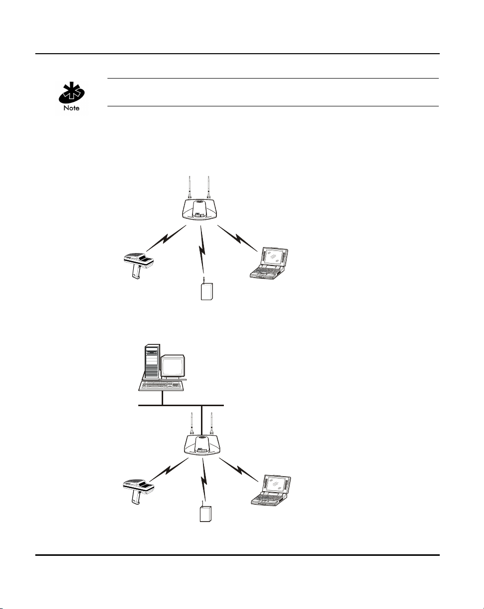
Select from the following topologies:
• A single AP used without the wired network provides a single-cell wireless
network for peer-to-peer MUs.
• A single AP can bridge the Ethernet and radio networks.
4 AP-4131 Access Point Product Reference Guide
Page 15
Introduction
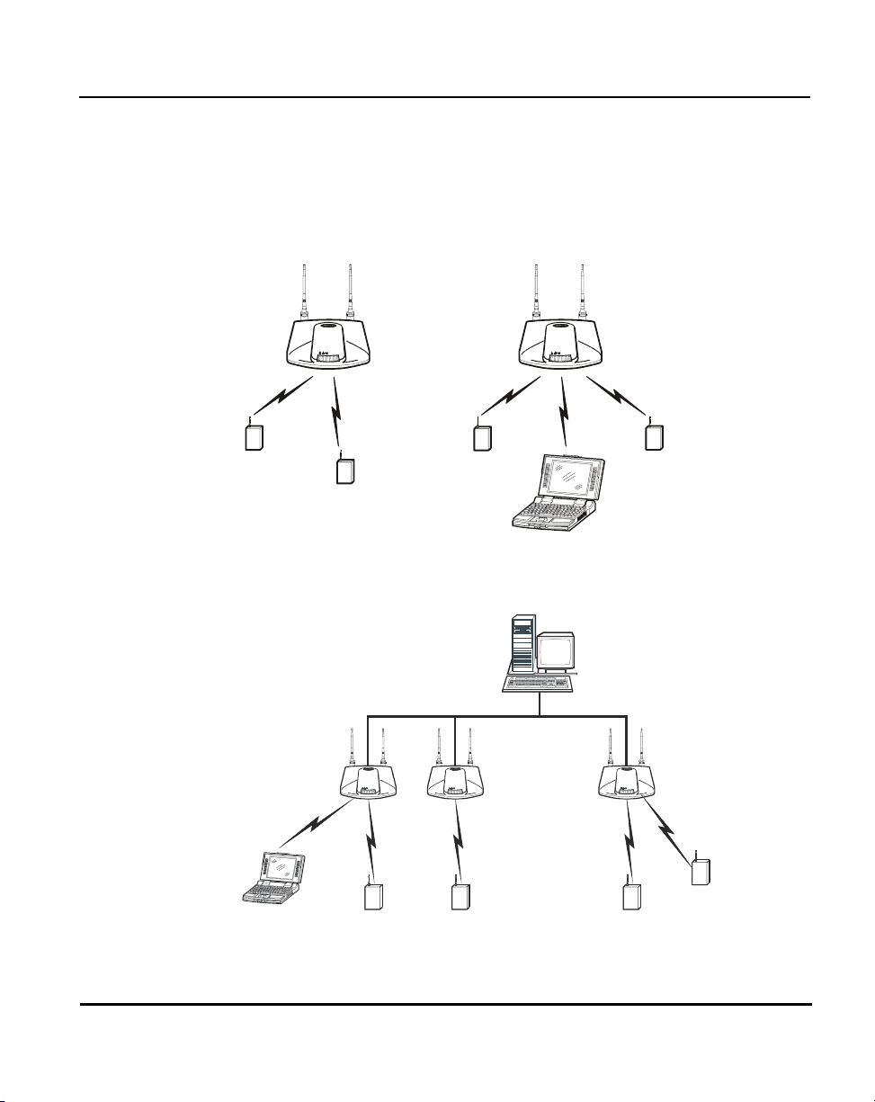
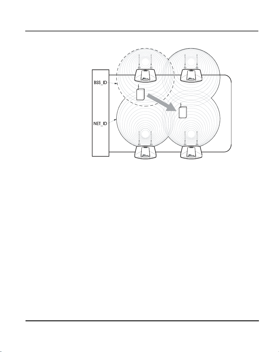
• Multiple APs can coexist as separate, individual networks at the same site
without interference using different Net_IDs. The Net_ID (ESS) can be
thought of as a Wireless LAN Network Identifier. These separate Wireless
LANs may be configured to use different channel assignments to avoid
RF interference.
• Multiple APs wired together provide a network with better coverage area
and performance when using the same Net_IDs.
AP-4131 Access Point Product Reference Guide 5
Page 16
Introduction
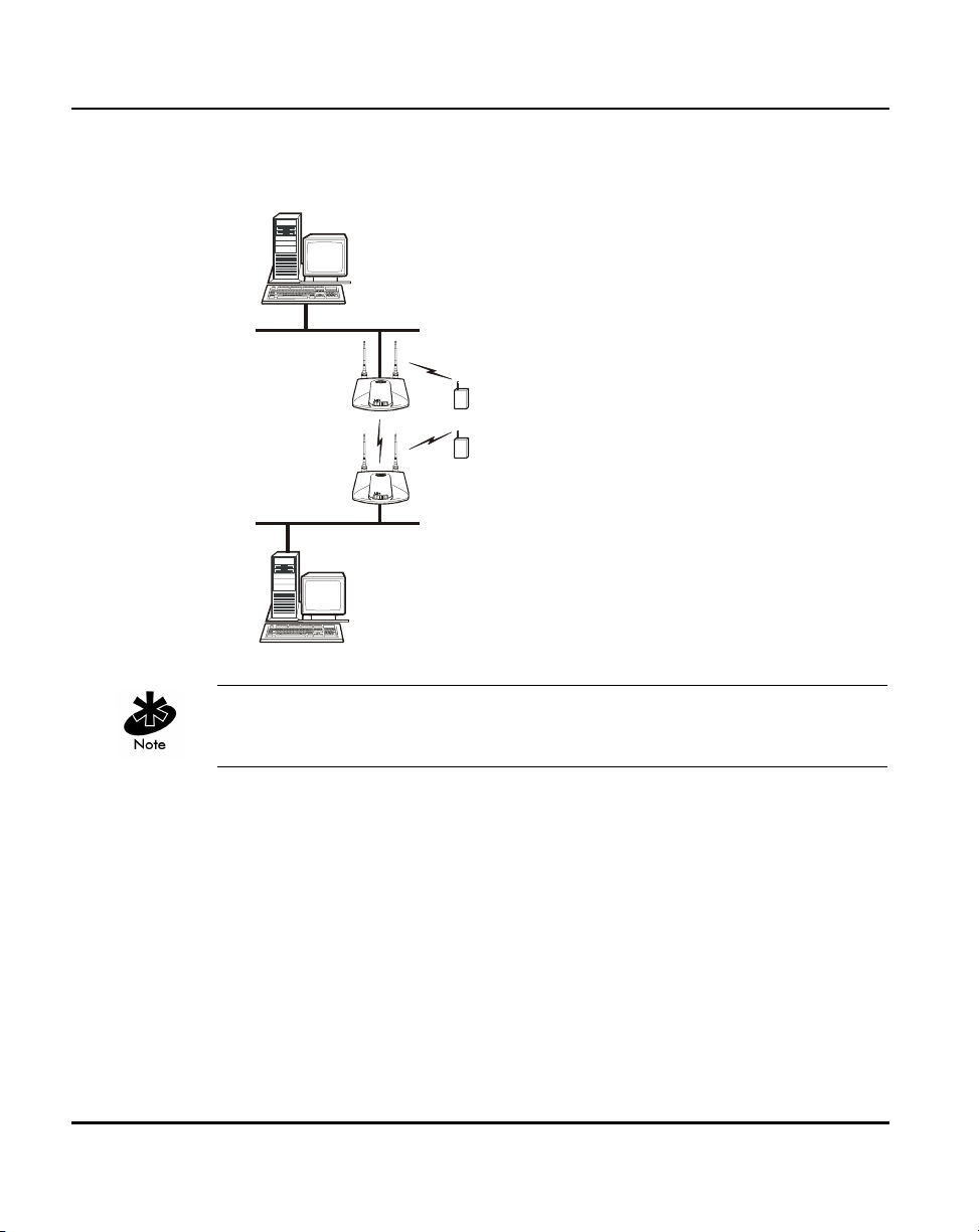
In WLAP mode, a wireless AP-to-AP connection functions:
• as a bridge to connect two Ethernet networks
Kerberos, EAP-TLS and the Mobile IP feature are not available when the
access point is operating in WLAP mode.
6 AP-4131 Access Point Product Reference Guide
Page 17
Introduction
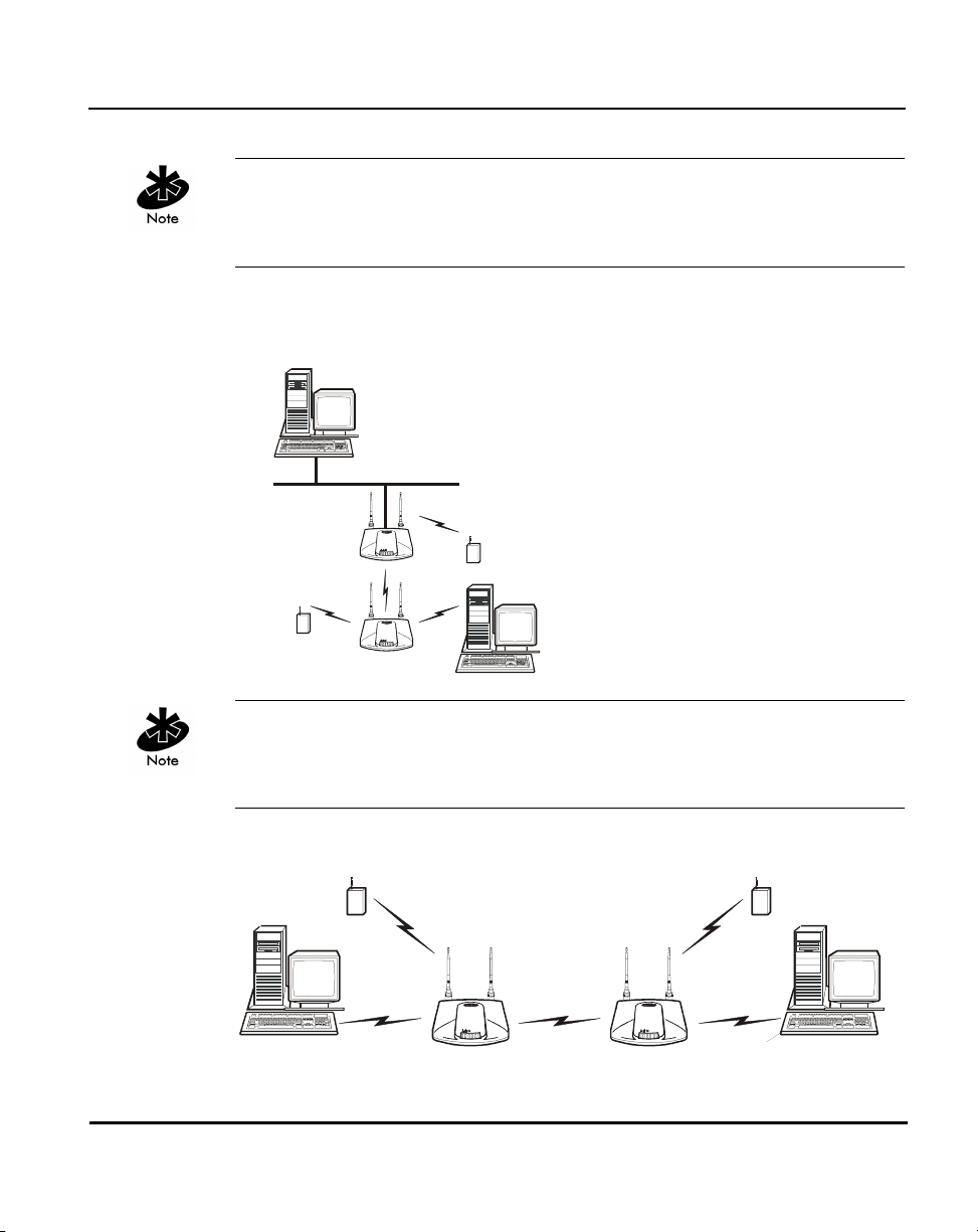
In WLAP mode, APs and MUs are required to have the same Preamble
settings to interoperate. Additionally, the root AP is required to be running
before the “leaf” or WLAP connection is established.
• as a repeater to extend coverage area without additional
network cabling.
When using a wireless AP-to-AP connection, use the optimal antenna
configuration for the site. For example, use a directional antenna when
establishing a dedicated wireless bridge or repeater.
• Each wireless AP can have connections with up to four other wireless APs.
AP-4131 Access Point Product Reference Guide 7
Page 18

Introduction
Using more than two WLAPs to establish a connection slows network
performance for all topologies. To increase WLAP performance, disable
WNMP Functions and AP-AP State Xchg parameters under the Set System
Configuration screen.
To set up an AP for wireless operation automatically, select the Enabled
option for the WLAP Mode parameter. To set these values, see section 2.5:
”Configuring Radio Parameters” on page 71.
The WLAP initialization process length depends on the time specified in
the WLAP Forward Delay field. See section 2.5: ”Configuring Radio
Parameters” on page 71.
1.2.2 Cellular Coverage
The AP establishes an average communication range with MUs called a
Basic Service Set (BSS) or cell. When in a particular cell the MU associates
and communicates with the AP of that cell. Each cell has a Basic Service Set
Identifier (BSS_ID). In IEEE 802.11, the AP MAC (Media Access Control)
address represents the BSS_ID. The MU recognizes the AP it associates with
using the BSS_ID.
Spectrum24 devices, like other network devices, have unique, hardwareencoded MAC or IEEE addresses. MAC addresses determine the device
sending or receiving the data. A MAC address is a 48-bit number written as
six hexadecimal bytes separated by colons. For example:
00:A0:F8:24:9A:C8
An MU recognizes the access point it associates with using the BSS_ID.
Adding access points to a single LAN establishes more cells to extend the
range of the network. Configuring the same ESS_ID (Extended Service Set
Identifier) on all access points make them part of the same Wireless LAN.
8 AP-4131 Access Point Product Reference Guide
Page 19
Introduction
APs with the same Net_ID (ESS) define a coverage area. The MU searches for
APs with a matching Net_ID (ESS) and synchronizes with an AP to establish
communications. This allows MUs within the coverage area to move
about or roam. As the MU roams from cell to cell, it switches APs. The switch
occurs when the MU analyzes the reception quality at a location and decides
which AP to communicate with based on the best signal strength and lowest
MU load distribution.
If the MU does not find an AP with a workable signal, it performs a scan to
find any AP. As MUs switch APs, the AP updates the association table.
The user can configure the Net_ID (ESS). A valid Net_ID (ESS) is an
alphanumeric, case-sensitive identifier up to 32 characters. Ensure all nodes
within one LAN use the same Net_ID (ESS) to communicate on the same
LAN. Multiple wireless LANs can coexist in a single environment by assigning
different Net_IDs (ESS) for APs.
AP-4131 Access Point Product Reference Guide 9
Page 20
Introduction
The Root AP and Association Process
By default, APs with WLAP Mode enabled and within range of each other
automatically associate and configure wireless operation parameters at
power up. This association process determines the wireless connection
viability and establishes the Root AP and subsequently designated WLAPs.
APs communicating wirelessly with one another require the same: Net_ID
(ESS), Encryption mode, Data Rate and Short RF Preamble settings.
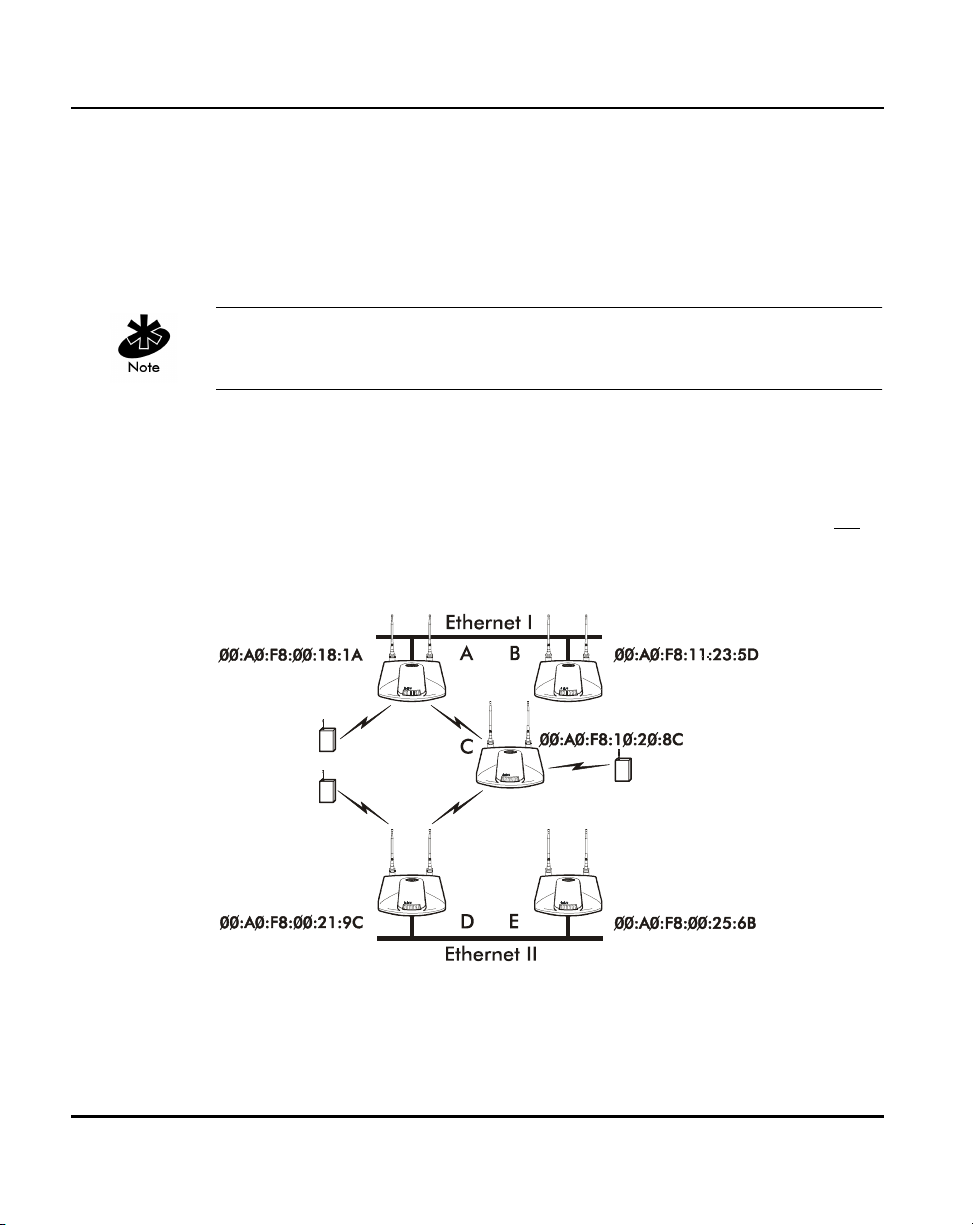
The root AP maintains the wireless connection among WLAPs by sending out
beacons, sending and receiving configuration BPDU (Bridge Protocol Data
Unit) packets between each designated WLAP. The WLAP with the lowest
WLAP ID becomes the Root AP. A concatenation of the WLAP Priority value
and the MAC address becomes the WLAP ID. All WLAPs associated with the
Root AP use the Root AP channel, DTIM (Delivery Traffic Indication Message)
and TIM (Traffic Indication Map) interval.
a
In this configuration, the WLAP Priority value is the default 8000 Hex. On
concatenating this value to the MAC addresses of the APs, AP A on Ethernet I
has the lowest WLAP ID with
800000A0F800181A, making it the Root AP.
AP C uses the AP A channel, DTIM and TIM interval.
10 AP-4131 Access Point Product Reference Guide
Page 21

If AP D on Ethernet II has data for a device on Ethernet I, it requires a bridge
or a repeater. In this configuration, AP C functions as a repeater. To ensure
transmission to devices on Ethernet I, AP D has to use the AP A channel,
DTIM and TIM interval.
The AP with lowest WLAP priority value is the Root AP. To manually designate
AP B as the Root AP, assign it a WLAP Priority value less than
section 2.5: ”Configuring Radio Parameters” on page 71.
IEEE 802.1d Spanning Tree Support
This protocol creates a loop-free topography with exactly ONE path between
every device and LAN. This is the shortest path from the Root AP to each
WLAP and LAN. If the connection between a WLAP and LAN fails, a new
route is calculated and added to the tree. All packet forwarding follows the
spanning tree path determined. APs in a network have to choose one AP as
the Root AP.
1.2.3 Site Topography
For optimal performance, locate MUs and APs away from transformers,
heavy-duty motors, fluorescent lights, microwave ovens, refrigerators and
other industrial equipment.
Introduction
8000 Hex. See
Signal loss can occur when metal, concrete, walls or floors block
transmission. Locate APs in open areas or add APs as needed to
improve coverage.
Site Surveys
A site survey analyzes the installation environment and provides users with
recommendations for equipment and its placement. The optimum placement
of 11 Mbps access points differs for 1 or 2 Mbps access points, because the
locations and number of access points required are different.
AP-4131 Access Point Product Reference Guide 11
Page 22

Introduction
Symbol recommends conducting a new site survey and developing a new
coverage area floor plan when switching from 1 or 2 Mbps frequencyhopping access points to 11 Mbps direct-sequence access points.
1.3 Access Point Functional Theory
To improve AP management and performance, users need to understand
basic AP functionality and configuration options. The AP includes features
for different interface connections and network management.
The AP provides MAC layer bridging between its interfaces. The AP monitors
traffic from its interfaces and, based on frame address, forwards the frames
to the proper destination. The AP tracks the frames sources and destinations
to provide intelligent bridging as MUs roam or network topologies change.
The AP also handles broadcast and multicast messages and responds to MU
association requests.
12 AP-4131 Access Point Product Reference Guide
Page 23
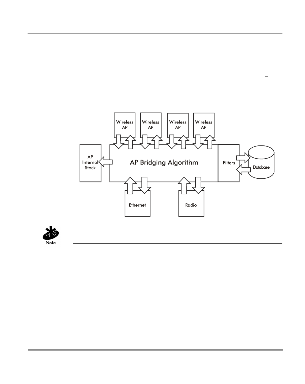
1.3.1 MAC Layer Bridging
The AP listens to all packets on all interfaces and builds an address database
using the unique IEEE 48-bit address (MAC address). An address in the
database includes the interface media that the device uses to associates
the AP. The AP uses the database to forward packets from one interface to
another. The bridge forwards packets addressed to unknown systems to the
Default Interface (Ethernet).
Introduction
with
The AP internal stack interface handles all messages directed to the AP.
Each AP stores information on destinations and their interfaces to facilitate
forwarding. When a user sends an ARP (Address Resolution Protocol) request
packet, the AP forwards it over all enabled interfaces (Ethernet, radio and
WLAP) except over the interface the ARP request packet was received.
On receiving the ARP response packet, the AP database keeps a record
of the destination address along with the receiving interface. With this
information, the AP forwards any directed packet to the correct destination.
The AP forwards packets for unknown destinations to the Ethernet interface.
AP-4131 Access Point Product Reference Guide 13
Page 24

Introduction
Transmitted ARP request packets echo back to other MUs.
The AP removes from its database the destination or interface information
that is not used for a specified time. The AP refreshes its database when it
transmits or receives data from these destinations and interfaces.
Filtering and Access Control
The AP provides facilities to limit the MUs that associate with it and the data
packets that can forward through it. Filters provide network security and
improve performance by eliminating broadcast/multicast packets from the
radio network.
The ACL (Access Control List) contains MAC addresses for MUs
allowed to associate with the AP. This provides security by preventing
unauthorized access.
The AP uses a disallowed address list of destinations. This feature prevents
the AP from communicating with specified destinations. This can include
network devices that do not require communication with the AP or its MUs.
Depending on the setting, the AP can keep a list of frame types that it
forwards or discards. The Type Filtering option prevents specific frames
(indicated by the 16-bit DIX Ethernet Type field) from being processed by
the AP. These include certain broadcast frames from devices that consume
bandwidth but are unnecessary to the wireless LAN. Filtering out
frames can also improve performance.
1.3.2 Auto Fallback to Wireless Mode
The AP supports an Auto Fallback to wireless mode when the hardware
Ethernet connection fails or becomes broken. The Auto Fallback function
operates only with an AP in WLAP mode and connected to the Ethernet
network. The AP resets itself and during initialization attempts to associate
with any other WLAP in the network.
14 AP-4131 Access Point Product Reference Guide
Page 25

See section 2.4 “Configuring System Parameters” on page 59 and section
2.5.1: ”Wireless AP Operation Parameters” on page 80.
To enable this feature, set the WLAP Mode to Link Required.
1.3.3 DHCP Support
The AP can use Dynamic Host Configuration Protocol (DHCP) to obtain a
leased IP address and configuration information from a remote server. DHCP
is based on BOOTP protocol and can coexist or interoperate with BOOTP.
Configure the AP to send out a DHCP request searching for a DHCP/BOOTP
server to acquire Kerberos security information, HTML, firmware or network
configuration files when a boot (an AP boot) takes place. Because BOOTP
and DHCP interoperate, whichever responds first becomes the server that
allocates information.
The AP can be set to only accept replies from DHCP or BOOTP servers or
both (this is the default setting). Setting DHCP to
and DHCP (configure network settings manually). If running both DHCP and
BOOTP, do not select BOOTP Only. BOOTP should only be used when the
server is running BOOTP exclusively. See section 2.3 “Access Point
Installation” on page 54.
Introduction
disabled disables BOOTP
The DHCP client automatically sends a DHCP request at an interval specified
by the DHCP server to renew the IP address lease as long as the AP is
running (This parameter is programmed at the DHCP server). For example:
Windows NT servers typically are set for 3 days.
AP-4131 Access Point Product Reference Guide 15
Page 26

Introduction
Program the DHCP or BOOTP server to transfer these files (Kerberos security
information, HTML, firmware or network configuration files) with these DHCP
options for the specific file or information to download:
DHCP Option Value
Firmware and HTML file 67 (filenames are separated by a space)
ESSID 128
Configuration filename 129
ACL filename 130
Kerberos enable/disable flag 131(set to 0 for disable or 1 for enable on
KDC name 132
KSS name 133
KSS port number 134
When the AP receives a network configuration change or is not able to renew
the IP address lease the AP sends out an SNMP trap if SNMP is configured.
1.3.4 Media Types
the DHCP server)
The AP supports bridging between Ethernet and radio media.
The Ethernet interface fully complies with Ethernet Rev. 2 and IEEE 802.3
specifications. The 4131 AP supports a 10/100Base-T wired connection. The
data transfer rate is 11 Mbps.
The radio interface conforms to IEEE 802.11 specifications. The interface
operates at 11 Mbps using direct-sequence radio technology. The AP
supports multiple-cell operations with fast roaming between cells. With the
direct-sequence system, each cell operates independently. Each cell provides
an 11 Mbps bandwidth. Adding cells to the network provides increased
coverage area and total system capacity. The AP supports MUs operating in
Power Save Polling (PSP) mode or Continuously Aware Mode (CAM) without
user intervention.
16 AP-4131 Access Point Product Reference Guide
Page 27

Introduction
The DB-9, 9-pin, RS-232 serial port provides a UI (User Interface)
connection. The UI provides basic management tools for the AP. The serial
link supports short haul (direct serial) or long haul (telephone-line)
connections. The AP is a DTE (Data Terminal Equipment) device with male
pin connectors for the RS-232 port. Connecting the AP to a PC requires a
null modem cable.
AP-4131 Access Point Product Reference Guide 17
Page 28
Introduction
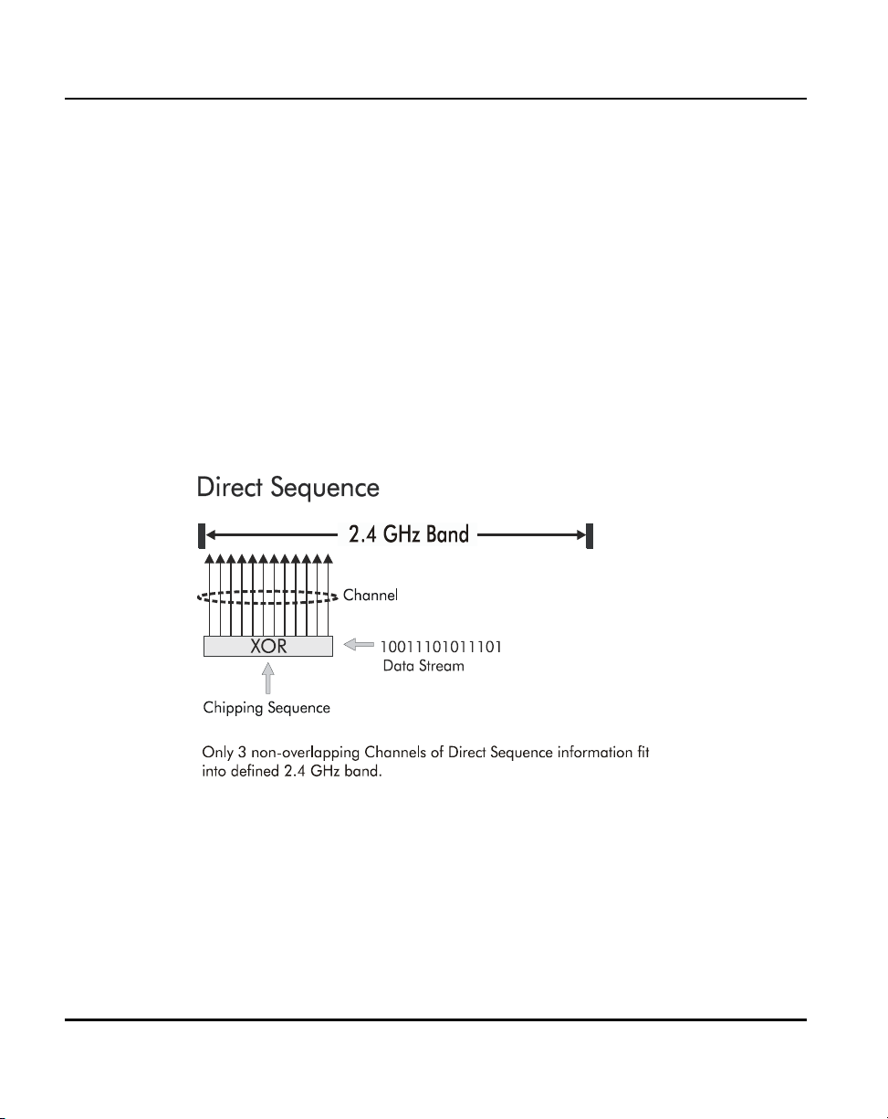
1.3.5 Direct-Sequence Spread Spectrum
Spread spectrum (broadband) uses a narrowband signal to spread the
transmission over a segment of the radio frequency band or spectrum.
Direct-sequence is a spread spectrum technique where the transmitted signal
is spread over a particular frequency range. The Spectrum24 AP-4131access
point uses Direct-Sequence Spread Spectrum (DSSS) for radio
communication.
Direct-sequence systems communicate by continuously transmitting a
redundant pattern of bits called a chipping sequence. Each bit of transmitted
data is mapped into chips by the access point and rearranged into a
pseudorandom spreading code to form the chipping sequence. The chipping
sequence is combined with a transmitted data stream to produce the AP
output signal.
18 AP-4131 Access Point Product Reference Guide
Page 29

Mobile Units receiving a direct-sequence transmission use the spreading
code to map the chips within the chipping sequence back into bits to recreate
the original data transmitted by the access point. Intercepting and decoding
a direct-sequence transmission requires a predefined algorithm to associate
the spreading code used by the transmitting access point to the receiving MU.
This algorithm is established by IEEE 802.11b specifications. The bit
redundancy within the chipping sequence enables the receiving MU to
recreate the original data pattern, even if bits in the chipping sequence are
corrupted by interference.
The ratio of chips per bit is called the spreading ratio. A high spreading ratio
increases the resistance of the signal to interference. A low spreading ratio
increases the bandwidth available to the user. The access point uses a
constant chip rate of 11Mchips/s for all data rates, but uses different
modulation schemes to encode more bits per chip at the higher data rates.
The access point is capable of an 11 Mbps data transmission rate, but the
coverage area is less than a 1 or 2 Mbps access point since coverage area
decreases as bandwidth increases.
1.3.6 MU Association Process
Introduction
APs recognize MUs as they associate with the AP. The AP keeps a list of the
MUs it services. MUs associate with an AP based on the following conditions:
• the signal strength between the AP and MU
• MUs currently associated with the AP
• the MUs encryption and authentication capabilities and the type enabled
• the MUs supported data rates (1 Mbps, 2 Mbps, 5.5 Mbps or 11 Mbps).
MUs perform preemptive roaming by intermittently scanning for APs and
associating with the best available AP. Before roaming and associating with
APs, MUs perform full or partial scans to collect AP statistics and determine
the direct-sequence channel used by the AP.
AP-4131 Access Point Product Reference Guide 19
Page 30

Introduction
Scanning is a periodic process where the MU sends out probe messages on
all channels defined by the country code. The statistics enable an MU to
reassociate by synchronizing its channel to the AP. The MU continues
communicating with that AP until it needs to switch cells or roam.
MUs perform full scans at start-up. In a full scan, an MU uses a sequential
set of channels as the scan range. For each channel in range, the MU tests
for CCA (Clear Channel Assessment). When a transmission-free channel
becomes available, the MU broadcasts a probe with the Net_ID (ESS) and
the broadcast BSS_ID. An AP-directed probe response generates an
MU ACK (Mobile Unit Acknowledgment) and the addition of the AP to the AP
table with a proximity classification. An unsuccessful AP packet transmission
generates another MU probe on the same channel. If the MU fails to receive
a response within the time limit, it repeats the probe on the next channel in
the sequence. This process continues through all channels in the range.
MUs perform partial scans at programmed intervals, when missing expected
beacons or after excessive transmission retries. In a partial scan, the MU
scans APs classified as proximate on the AP table. For each channel,
the MU tests for CCA. The MU broadcasts a probe with the Net_ID (ESS)
and broadcast BSS_ID when the channel is transmission-free. It sends an
ACK to a directed probe response from the AP and updates the AP table.
An unsuccessful AP packet transmission causes the MU to broadcast another
probe on the same channel. The MU classifies an AP as out-of-range in the
AP table if it fails to receive a probe response within the time limits. This
process continues through all APs classified as proximate on the AP table.
20 AP-4131 Access Point Product Reference Guide
Page 31

Introduction
An MU can roam within a coverage area by switching APs. Roaming
occurs when:
• an unassociated MU attempts to associate or reassociate with an
available AP
• the supported rate changes or the MU finds a better transmit rate with
another AP
•the RSSI (received signal strength indicator) of a potential AP exceeds the
current AP
• the ratio of good-transmitted packets to attempted-transmitted packets
falls below a threshold.
An MU selects the best available AP and adjusts itself to the AP directsequence channel to begin association. Once associated, the AP begins
forwarding any frames it receives addressed to the MU. Each frame contains
fields for the current direct-sequence channel. The MU uses these fields to
resynchronize to the AP.
The scanning and association process continues for active MUs. This process
allows the MUs to find new APs and discard out-of-range or deactivated APs.
By testing the airwaves, the MUs can choose the best network connection
available.
1.3.7 Mobile IP
The Internet Protocol identifies the MU point of attachment to a network
through its IP address. The AP routes packets according to the location
information contained in the IP header. If the MU roams across routers to
another subnet, the following situations occur:
• The MU changes its point of attachment without changing its IP address,
causing forthcoming packets to become undeliverable.
• The MU changes its IP address when it moves to a new network, causing
it to lose connection.
Mobile IP enables an MU to communicate with other hosts using
only its home IP address after changing its point-of-attachment to the
internet/intranet.
AP-4131 Access Point Product Reference Guide 21
Page 32

Introduction
Mobile IP is like giving an individual a local post office forwarding address
when leaving home for an extended period. When mail arrives for the
individual home address, it is forwarded by the local post office to the
current care-of-address. Using this method, only the local post office
requires notification of the individual current address. While this example
represents the general concept of Mobile IP operation and functionality,
it does not represent the implementation of Mobile IP used.
A tunnel is the path taken by the original packet encapsulated within the
payload portion of a second packet to some destination on the network.
A Home Agent is an AP acting as a router on the MU home network.
The home agent intercepts packets sent to the MU home address and
tunnels the message to the MU at its current location. This happens as
long as the MU keeps its home agent informed of its current location on
some foreign link.
A Foreign Agent is an AP acting as a router at the MU location on a foreign
link. The foreign agent serves as the default router for packets sent out
by the MU connected on the same foreign link.
A care-of-address is the IP address used by the MU visiting a foreign link.
This address changes each time the MU moves to another foreign link.
It can also be viewed as an exit point of a tunnel between the MU home
agent and the MU itself.
The S24 Mobile IP (roaming across routers) feature enables an MU
on the Internet to move from one subnet to another while keeping its
IP address unchanged.
To configure this feature, see section 2.4: ”Configuring System Parameters”
on page 59. The Mobile IP feature is not available if either Kerberos or
EAP-TLS have been enabled as access point security measures.
22 AP-4131 Access Point Product Reference Guide
Page 33

Introduction
The scanning and association process continues for active MUs.
This allows the MUs to find new APs and discard out-of-range or
deactivated APs. By testing the airwaves, the MUs can choose the best
network connection available.
The following diagram illustrates Mobile IP (roaming across routers):
Set the MU for Mobile IP as specified in the MU user documentation.
Security has become a concern to mobile users. Enabling the Mobile-Home
MD5 key option in the System Configuration menu generates a 16-byte
checksum authenticator using an MD5 algorithm. The MU and AP share the
checksum, called a key, to authenticate transmitted messages between them.
The AP and MU share the key while the MU is visiting a foreign subnet.
The MU and AP have to use the same key. If not, the AP refuses to become
the Home Agent for the MU. The maximum key length is 13 characters.
The AP allows all printable characters.
AP-4131 Access Point Product Reference Guide 23
Page 34

Introduction
1.3.8 Supporting CAM and PSP Stations
CAM (Continuously Aware Mode) stations leave their radios on continuously
to hear every beacon and message transmitted. These systems operate
without any adjustments by the AP. A beacon is a uniframe system packet
broadcast by the AP to keep the network synchronized. A beacon includes
the Net_ID (ESS), the AP address, the Broadcast destination addresses,
a time stamp, a DTIM (Delivery Traffic Indication Message) and the TIM
(Traffic Indication Map).
PSP (Power Save Polling) stations power off their radios for short periods.
When a Spectrum24 MU in PSP mode associates with an AP, it notifies the AP
of its activity status. The access point responds by buffering packets received
for the MU. The Spectrum24 adapters use a PSP performance index from 1
to 5, where 1 provides the quickest response time and 5 provides the most
efficient power consumption.
The performance index determines how long the adapter stays in CAM after
transmit or receive activity. Regardless of the performance index used,
adapters switch to CAM for data reception/transmission. The awake interval
in PSP performance index 1 is long enough to allow for round-trip packet
response times. The packet response time in PSP performance index 5 is only
25 msec, the adapter goes back to sleep and requires another wake up
period to receive data.
When the MU wakes up and sees its bit set in the TIM, it issues a short frame
to the AP for the packets stored. The AP sends them to the MU and the MU
issues another short frame when the data has been received and is ready to
go back to PSP. A DTIM field, also called a countdown field, informs MUs of
the next window for listening to broadcast and multicast messages. When the
AP has buffered broadcast or multicast messages for associated MUs, it
sends the next DTIM with a DTIM Interval value. To prevent a PSP-mode MU
from sleeping through a DTIM notification, select a PSP mode value less than
or equal to the DTIM value. PSP-mode MUs hear the beacons and awaken to
receive the broadcast and multicast messages.
24 AP-4131 Access Point Product Reference Guide
Page 35

A TIM is a compressed virtual bitmap identifying the AP associated MUs in
PSP mode that have buffered directed messages. MUs issue a poll request
when APs issue a TIM. A beacon with the broadcast-indicator bit set causes
the MU to note DTIM Count field value. The value informs the MU of the
beacons remaining before next DTIM. This ensures the MU turns on the
receiver for the DTIM and the following BC/MC packet transmissions.
1.3.9 Data Encryption
Any wireless LAN device (including Spectrum24 devices operating on a
wireless network) faces possible information theft. Theft occurs when an
unauthorized user eavesdrops to obtain information illegally. The absence of
a physical connection makes wireless links particularly vulnerable to this form
of theft.
Encryption becomes the most efficient method in preventing information
theft and improving data security. Encryption entails scrambling and coding
information, typically with mathematical formulas called algorithms, before
the information is transmitted. An algorithm is a set of instructions or formula
for scrambling the data. A key is the specific code used by the algorithm to
encrypt or decrypt the data. Decryption is the decoding and unscrambling of
received encrypted data.
Introduction
The same device, host computer or front-end processor, usually performs
both encryption and decryption. The data transmit or receive direction
determines whether the encryption or decryption function is performed.
The device takes plain text, encrypts or scrambles the text typically by
mathematically combining the key with the plain text as instructed by the
algorithm, then transmits the data over the network. At the receiving end
another device takes the encrypted text and decrypts, or unscrambles, the
text revealing the original message. An unauthorized user can know the
algorithm, but cannot interpret the encrypted data without the appropriate
key. Only the sender and receiver of the transmitted data know the key.
Symbol uses the Wired Equivalent Privacy (WEP) algorithm, specified in
IEEE 802.11 section 8, for encryption and decryption. WEP uses the same
key for both encrypting and decrypting text. Typically an external key service
distributes the key. Users should change the key often for added security.
AP-4131 Access Point Product Reference Guide 25
Page 36

Introduction
IEEE 802.11 defines two types of authentication, Open System and Shared
Key. Open system authentication is a null authentication algorithm. Shared
key authentication is an algorithm where both the AP and the MU share an
authentication key to perform a checksum on the original message. Both
40-bit and 128-bit shared key encryption algorithms are supported in the
Symbol Spectrum24 Access Point. Devices are required to use the same
encryption algorithm to interoperate. APs and MUs cannot transmit and
receive if the AP is using 128-bit encryption and the MU is using a 40-bit
encryption algorithm.
By default, IEEE 802.11 devices operate in an open system network where
any wireless device can associate with an AP without authorization.
A wireless device with a valid shared key is allowed to associate with the AP.
Authentication management messages (packets) are unicast, meaning
authentication messages transmit from one AP to one MU only, not
broadcast or multicast.
1.3.10 Kerberos Authentication
Kerberos can be installed on devices supporting Windows 2000, NT 4.0 and
95/98. However, the optional KSS resides on a Windows 2000 server. The
Spectrum24 Plus Pack is required on all devices supporting Kerberos.
Authentication is critical for the security of any wireless LAN device, including
a Spectrum24 device operating on a wireless network. Traditional
authentication methods are not suitable for use in wireless networks where
an unauthorized user can monitor network traffic and intercept passwords.
The use of strong authentication methods that do not disclose passwords is
necessary. Symbol uses the Kerberos authentication service protocol
(specified in RFC 1510), to authenticate users/clients in a wireless network
environment and to securely distribute the encryption keys used for both
encrypting and decrypting plain text.
26 AP-4131 Access Point Product Reference Guide
Page 37

Introduction
For a detailed description of the Kerberos authentication service protocol
refer to RFC 1510: Kerberos Network Authentication Service (V5).
A basic understanding of RFC 1510 Kerberos Network Authentication Service
(V5) is helpful in understanding how Kerberos functions. Kerberos requires
the installation of the KSS on a Windows 2000 server. By default,
Spectrum24 devices operate in an open system network where any wireless
device can associate with an AP without authorization. Kerberos requires
Spectrum24 device authentication before access to the wired network is
permitted. Kerberos cannot operate when the AP is in wireless (WLAP) mode.
If DHCP is disabled or a DHCP server is not available, use the Kerberos
Authentication screen to manually configure Kerberos.
Kerberos can be enabled automatically in an AP physically attached to an
Ethernet network from a DHCP server on the same network. Program the
DHCP server with the Kerberos and KSS options found in section 1.3.3:
”DHCP Support” on page 15. When the AP boots up, it automatically
requests the KSS for Kerberos parameters. If a DHCP server is not present
manually enable Kerberos in the AP. A Key Distribution Center (KDC)
contains a database of authorized users and passwords within its realm (a
realm is the Kerberos equivalent of a Windows domain). The KDC is
responsible for user authentication, the distribution of session/service keys
(tickets).
The KSS requires restarting whenever the KDC is rebooted.
The KDC contains two components:
AP-4131 Access Point Product Reference Guide 27
Page 38

Introduction
• Authentication Service (AS)
– Provides the authentication ticket containing information about the
client and the session key used with the KDC.
• Ticket Granting Ticket Service (TGS)
– Permits devices to communicate with a service (this could be any
application or service such as the AP RF services).
The default expiration time of a ticket is 12 hours (for the AP) and is not user
configurable. If the lifetime of a ticket in the KDC's security policy is different
than what is requested, the KDC selects the shortest expiration time between
the two. Each time a ticket is generated a new session and WEP encryption
key is generated.
The KDC resides on the Kerberos server (the Kerberos server can also be the
DNS server). In addition to the KDC, a Kerberos Setup Service (KSS) is
installed on the Kerberos server. The KSS runs as a client on the KDC server
when initially launched. The KSS can be used to administer Spectrum24
devices authorized on the network. For example, an AP on the Access Control
List (ACL) is lost or stolen. The KSS marks the AP (using the MAC address of
the AP) as not authorized and notifies the administrator if the missing AP
appears elsewhere on the network attempting authentication. All clients
(MUs), KDC and services (APs) participating in the Kerberos authentication
system must have their internal clocks synchronized within a specified
maximum amount of time (known as clock skew). The KSS uses Network
Time Protocol (NTP) or the system clock on the Kerberos server to provide
clock synchronization (timestamp) between the KDC and APs as part of the
authentication process. Clock synchronization is essential since the expiration
time is associated with each ticket. If the clock skew is exceeded between any
of the participating hosts, requests are rejected.
Additionally, the KSS provides a list of authorized APs and other security setup
information that the KDC uses to authenticate clients. When setting up KSS,
assign APs an ESSID as the User ID to authenticate with the KDC.
28 AP-4131 Access Point Product Reference Guide
Page 39

Introduction
When the AP boots up it contacts the KSS to obtain KDC information. The AP
sends an Authentication Service Request (AS_REQ) to the KDC. The KDC
looks up the username (ESSID in the case of APs), the associated password,
and other authentication information including the current time stamp. If the
AP has provided the correct information the KDC responds with an
Authentication Service Response (AS_REP). These initial Kerberos messages
are used to obtain the client credentials and session key known as the Ticket
Granting Ticket. The AP verifies the information and is authenticated with the
KDC. After the AP validates the message, it turns on its RF services but does
not bridge data packets until the MU has been authenticated.
An MU is required to authenticate with the KDC before the AP allows any RF
bridging. The MU appears to associate but because it has not been
authenticated, the AP does not bridge any non-Kerberos authentication type
packets to the network. The AP acts as a conduit (the AP will proxy the MU
requests/replies to and from the KDC) passing AS_REQ, AS_REP, Ticket
Granting Service Request (TGS_REQ) and Ticket Granting Service Reply
(TGS_REP) between the clients and the KDC until authentication is successful.
Once a ticket is issued and the authentication process is completed, the AP
continues to bridge data with the MU even if the KDC/KSS are unavailable.
Once the ticket expires, the AP/MU stop passing Kerberos data if the
KDC/KSS are still unavailable to issue tickets.
The authentication process for an MU is similar to an AP authentication. The
difference being that the MU/client sends all requests through the AP with
one additional step. The additional step is sending the KDC a TGS_REQ for
RF services. The TGS_REQ message is encrypted with the encryption key that
the MU received during the first part of the authentication process. The ticket
the MU received in the AS_REP includes: the ESSID of the AP whose RF
services it wishes to access. The AP proxies (forwards) the MU request to the
KDC. The KDC verifies the request and responds with a TGS_REP sent to the
MU through the AP which proxies the reply to the MU. The AP proxy does not
read the MU TGS_REQ but replaces the header information with an IP
header (the AP IP address). Conversely, the AP replaces the TGS_REP header
AP-4131 Access Point Product Reference Guide 29
Page 40

Introduction
with a WNMP header and forwards the response to the MU. Once the MU
has verified the message it prepares an Application Request (AP_REQ) for the
AP. This AP_REQ contains the ticket the KDC has sent to the MU. The AP
decrypts the ticket. If the ticket is valid the AP responds with an AP_REP (the
AP generates and includes128 bit WEP encryption key in the reply) and
permits the MU to bridge data.
The KDC cannot authenticate an MU with administrator as the username.
30 AP-4131 Access Point Product Reference Guide
Page 41

Enabling Kerberos disables Telnet, SNMP and Web services. Configure the
AP through a direct serial connection if needed. Configure SNMP to be "Read
Only" or "Read/Write" from the KSS. Disabling Kerberos returns (Kerberos
disabled is the default setting) Telnet, SNMP and Web services to their
previous setting. If an AP cannot be accessed through a serial connection
and SNMP is not configured for read/write, use of DHCP option 131 is
another way to disable Kerberos.
The KSS in a Spectrum24 environment runs only on a Windows 2000 server
with Active Directory enabled. Future supported platforms include Linux,
Solaris, SCO Unixware and HP-UX.
1.3.11 KSS Open Enrollment
When the KSS startup and KDC authentication completes successfully, the
KSS opens a listening TCP/IP connection port and waits for any AP (several
APs can connect to the KSS concurrently) that requests KSS AP setup services.
Each AP requires an AP Setup Account entry. Open Enrollment mode allows
the system administrator to enter information for APs with the same ESSID
and therefore the same Kerberos Principal. The system administrator creates
an AP Setup Account entry (enter all the Open Enrollment properties
including a Kerberos Principal) in Open Enrollment mode. Complete the
Kerberos account with this Principal in the Kerberos Account database. When
the KSS Listening mode and Open Enrollment is enabled (by selecting a
check box in the Kerberos Setup Service Property page), KSS provides the
default AP Setup Account and the corresponding Kerberos Account to the AP.
A new AP Setup Account record is created for the AP using the default Open
Enrollment properties. The KSS continues to do this until Open Enrollment is
disabled. Access points with a "Disabled" status or expired range entries in
the KSS are not allowed to accept Open Enrollment information. This
provides a tool to block APs that are known to have been stolen or missing.
Introduction
AP-4131 Access Point Product Reference Guide 31
Page 42

Introduction
1.3.12 KSS Databases
The KSS has two databases. One database stores valid access points (AP
setup account). The other database stores Kerberos account information
(Kerberos entry account). The AP setup account database stores validation
information for an AP. This database uses the AP MAC address as a Primary
Key. The entry includes the range of time the AP is allowed access and status
information. A Foreign Key entry for a record in the AP setup account is the
Kerberos Principal for this AP. This Foreign Key is used as an index to the
Kerberos Entry account database to retrieve other Kerberos information for
the AP. The Kerberos Entry account database stores specific Kerberos
information for APs. It uses the Kerberos Principal (AP’s ESSID) as its Primary
Key, and it includes other Kerberos network information that an AP needs to
authenticate with the KDC.
When an AP requests information from the KSS, the KSS queries the AP Setup
database to validate the AP. If the AP is valid the KSS will query its Kerberos
Entry account database for the AP’s Kerberos information. The KSS packages
the information and sends it to the AP.
APs with the same ESSID will share common Kerberos Entry account
information since the ESSID is used as an AP Kerberos Principal.
1.3.13 Roaming and Authentication
When an MU authenticates through the KDC it specifies that it wants access
to the AP that it has associated with. When the MU completes the full ASREQ/AS-REP, TGT-REQ/TGT-REP, and AP-REQ/AP-REP hand-shake sequence,
it possesses a ticket and a session key (WEP encryption key) for use in
communicating with that AP. However, since the password and the username
are the same for all APs, that ticket decrypts and validates with any AP.
When a MU roams, after it has associated with the new AP it sends to that AP
the same AP-REQ that it sent to the AP that it first authenticated with. The new
AP decrypts the ticket and validates the authenticator in the AP-REQ message.
It then sends back an AP-REP with a new session key to the MU and normal
communication through the new AP can continue.
32 AP-4131 Access Point Product Reference Guide
Page 43

1.3.14 Mixed Mode Security
Mixed mode security allows a single access point to transmit and receive with
mobile units operating with different encryption algorithms (WEP, Kerberos,
EAP-TLS). Using mixed mode, additional access points are not needed to
support mobile units simply because they are using different encryption
schemes.
1.3.15 Web Management Support
A Symbol Spectrum24 Access Point includes an HTTP Web server to allow the
user to access and manage the AP with a standard Java-compatible browser.
This capability provides the user with a Web-based interface for
configuration and firmware download.
Using either NetScape Navigator 4.5 or greater or Microsoft Internet
Explorer 4.0 or greater, point the browser at either the IP address of the AP
or, if the AP is defined in DNS, at the DNS name of the AP. A window opens
that allows the user to access configuration, setup and performance
information for the AP as well as additional diagnostic information.
Introduction
Disable Kerberos Encryption to use a Web server to configure access
point settings.
AP-4131 Access Point Product Reference Guide 33
Page 44

Introduction
1.3.16 Management Options
Managing Spectrum24 includes viewing network statistics and setting
configuration options. Statistics track the network activity of associated
MUs and data transfers on the AP interfaces.
The AP requires one of the following to perform a custom installation or
maintain the Spectrum24 network:
• SNMP (Simple Network Management Protocol)
• wired LAN workstation with a Telnet client
• terminal or PC with RS-232 connection and ANSI emulation
Make configuration changes to APs individually. Each AP requires an
individual IP address.
Programmable SNMP Trap Support
The SNMP protocol defines the method for obtaining information about
networks operating characteristics and changing router and gateway
parameters. The SNMP protocol consists of three elements:
• management stations
• management information (MIB)
• a management protocol (SNMP).
Nodes can perform as hosts, routers, bridges or other devices that can
communicate status information. An SNMP Manager is a node that runs the
SNMP management process to systematically monitor and manage the
network. The management station performs network management by
running application management software.
An SNMP trap is an alert to all configured management stations of some
significant event that occurred on the network. The management station
queries all stations for details of each specific event, including what, when
and where the event took place and the current status of the node or
network. The format or structure is defined in the SNMP protocol. The MIB
defines what and who monitors the variables.
34 AP-4131 Access Point Product Reference Guide
Page 45

Introduction
Using SNMP
The AP includes SNMP agent versions accessible through an SNMP manager
application such as, HP Open View or Cabletron Spectrum MIB browser.
The SNMP agent supports SNMP versions 1 and a subset of version 2, MIB II,
the 802.11 MIB and one Symbol proprietary MIB (Management Information
Base). The SNMP agent supports read-write, read-only or disabled modes.
The AP supports traps that return to the SNMP manager when certain events
occur. The Symbol MIB is available on the Spectrum24 High Rate 11 Mbps
Wireless LAN Software CDROM or from http://www.symbol.com/services/
downloads/download_spec24.html.
Disable Kerberos Encryption to use SNMP to configure access point settings.
Increased MIB Support
The MIB (Management Information Base) has ten categories defining
what the management station needs to understand and which objects the
station manages.
AP-4131 Access Point Product Reference Guide 35
Page 46

Introduction
Using the UI
The UI (User Interface) is a maintenance tool integrated into the AP.
It provides statistical displays, AP configuration options and firmware
upgrades. Access to the UI requires one of the following:
Telnet Client Access to the AP built-in Telnet server from any interface
including remote Ethernet connections.
See section 2.1.1: ”Using Telnet” on page 37.
Direct Serial
Connection
Dial Up Access The dial-up access method requires a communication
SNMP Using a
MIB Browser
Web Browser Access to the AP built-in Web server from any AP
The AP acts as a DTE device to connect directly to
another DTE device with a null-modem serial cable.
The direct serial access method requires a
communication program with ANSI emulation.
See section 2.1.2: ”Using a Direct Serial Connection” on
page 39.
program with ANSI emulation on the remote terminal
or PC. The terminal or PC dials to an AP with a modem
connection. The AP supports connection to a
Hayes-compatible 28,800-baud or faster modem.
See section 2.1.3: ”Using a Dial-Up Connection” on page
40.
Access to the AP SNMP function using a MIB Browser.
Typically a Network Manager uses this feature, however,
Symbol does not recommend accessing the AP using this
interface method.
interface including Ethernet connections.
See section 2.1.4: ”Using a Web Browser” on page 41.
36 AP-4131 Access Point Product Reference Guide
Page 47

Chapter 2 Configuring the AP
AP configuration requires setting up a connection to the AP and gaining
access to the UI (User Interface). The methods of accessing the UI are Serial,
Telnet, Web, and SNMP. DHCP is enabled on the AP by default. Initial
network configuration can be obtained from a DHCP server. All except Serial
require the configuration of an IP address.
To access the AP through the serial port and terminal emulation program,
connect to the DB9 serial port using a null modem cable. Set the terminal
emulation program for 19,200 bps, 8 bits, No parity, 1 Stop Bit and No flow
control. Select the AP Installation screen and enter the appropriate IP
configuration parameters for the network.
The dot in front of certain parameters, functions or options (.Antenna
Selection Primary Only
same Net_ID (ESS) when choosing the
perform this option only among the same hardware platforms and same
firmware versions.
) indicates these items update to all APs with the
Save ALL APs-[F2] option. Users can
2.1 Gaining Access to the UI
The method for establishing access to the UI depends on the connection
used. Select the setup that best fits the network environment.
2.1.1 Using Telnet
Using a Telnet session to gain access to the UI requires that a remote station
have a TCP/IP stack. The remote station can be on the wired or wireless LAN.
To access the AP from the workstation:
1. From the DOS prompt, Telnet to the AP using its IP address:
Telnet xxx.xxx.xxx.xxx
AP-4131 Access Point Product Reference Guide 37
Page 48

Configuring the AP
2. At the prompt type the password:
Symbol
The password is case-sensitive.
3. Press the ESC key. The AP displays the Main Menu:
Symbol Access Point
MAIN MENU
Show System Summary AP Installation
Show Interface Statistics Special Functions
Show Forwarding Counts Set System Configuration
Show Mobile Units Set RF Configuration
Show Known APs Set Access Control List
Show Ethernet Statistics Set Address Filtering
Show RF Statistics Set Type Filtering
Show Misc. Statistics Set SNMP Configuration
Show Event History Set Event Logging Configuration
Enter Admin Mode
– If the session is idle (no input) for the configured time, the session
terminates.
– Press CTRL+D to manually terminate the session.
4. Proceed to section 2.14.1: ”Update Using TFTP” on page 139 to update
the AP firmware or HTML file or to section 2.2: ”Navigating the UI” on
page 48.
38 AP-4131 Access Point Product Reference Guide
Page 49

2.1.2 Using a Direct Serial Connection
The factory-configured AP accepts a dial-up connection between the AP and
a modem. A UI connection requires a straight-through cable between the
modem and the AP. See section 2.2.3: ”Configuring for Dial-Up to the UI” on
page 53. The AP serial port is a DB-9, 9-pin male connector. The serial port
allows a UI connection to a configuration PC. Connecting the AP directly to a
PC with a 9-pin serial port requires a null modem cable with the following
configuration:
Assuming the UI and serial port are enabled on the AP:
1. Apply Power to the AP.
2. Attach a null modem serial cable from the AP to the terminal or PC
serial port.
3. From the terminal, start the communication program, such as
HyperTerminal for windows.
4. Select the correct COM port along with the following parameters.
emulation ANSI
baud rate 19200 bps
data bits 8
stop bits 1
parity none
flow control none
Configuring the AP
There is no password requirement.
AP-4131 Access Point Product Reference Guide 39
Page 50

Configuring the AP
5. Press ESC to refresh the display. The AP displays the Main Menu.
Symbol Access Point
MAIN MENU
Show System Summary AP Installation
Show Interface Statistics Special Functions
Show Forwarding Counts Set System Configuration
Show Mobile Units Set RF Configuration
Show Known APs Set Access Control List
Show Ethernet Statistics Set Address Filtering
Show RF Statistics Set Type Filtering
Show Misc. Statistics Set SNMP Configuration
Show Event History Set Event Logging Configuration
Enter Admin Mode
6. Refer to section 2.12.2: ”Updating Using Xmodem” on page 132 to
update the AP firmware or HTML file or to section 2.2: ”Navigating the
UI” on page 48.
7. Exit the communication program to terminate the session.
2.1.3 Using a Dial-Up Connection
A dial-up connection requires a straight-through cable between the modem
and the AP. The remote PC requires a modem and a communication
program (Microsoft Windows Terminal program).
See Appendix B for information on the modems supported by the AP.
1. Set Modem Connected to Yes in the System Configuration screen.
2. Attach a straight-through serial cable from the AP to the modem.
3. Verify the modem connects to the telephone line and has power.
Refer to the modem documentation for information on verifying
device power.
4. From the remote terminal, start the communication program.
40 AP-4131 Access Point Product Reference Guide
Page 51

Configuring the AP
5. Select the correct serial port along with the following parameters.
emulation ANSI
baud rate 19200 bps
data bits 8
stop bits 1
parity none
flow control none
6. Dial out to the AP with the correct telephone number.
No password is required.
7. Press ESC to refresh the display. The AP displays the Main Menu.
Symbol Access Point
MAIN MENU
Show System Summary AP Installation
Show Interface Statistics Special Functions
Show Forwarding Counts Set System Configuration
Show Mobile Units Set RF Configuration
Show Known APs Set Access Control List
Show Ethernet Statistics Set Address Filtering
Show RF Statistics Set Type Filtering
Show Misc. Statistics Set SNMP Configuration
Show Event History Set Event Logging Configuration
Enter Admin Mode
2.1.4 Using a Web Browser
A Web browser is a program used to view Web documents or pages. The
browser retrieves the requested page, interprets its text and displays the page
on a computer screen.
Using a Web browser to gain access to the UI requires the workstation to
have a TCP/IP stack and a Web browser. The remote station can be on the
wired or wireless LAN.
AP-4131 Access Point Product Reference Guide 41
Page 52

Configuring the AP
The Web browser (Internet Explorer 4.0 or greater or Netscape) requires
JavaScript to gain access to the UI.
Setup Network Web Server Help File Access
A network Web server is required to access the Help file from the Access Point
Configuration Management System Web pages. This procedure applies to the
Microsoft Internet Information Server. The network Web server can be
different, if so, some of the procedures differ.
Only Network or System Administration personnel should configure the
network Web server.
To create the Help file on a network Web server:
1. Create a directory on the network Web server for the AP Web Site Help
Files to reside.
Often this subdirectory is C:\InetPub\wwwRoot.
2. Copy the *.gif and *.htm files to this directory/folder.
The files are found in the x:\firmware\AP\AP Web Site\Help File
directory.
Where x is the letter assigned to the computer CDROM drive.
This installation example is for Windows NT 4.0.
3. From the windows Task Bar select Start.
4. From the drop down menu select Programs.
5. From this menu select Microsoft Internet Server(common).
42 AP-4131 Access Point Product Reference Guide
Page 53

Configuring the AP
6. From this menu select Internet Service Manager to launch the
Internet Information Server Service Manager.
7. Click on the Web service.
Ensure the server WWW service is running.
8. Select Properties.
9. Select Service Properties to display the WWW service properties
for the server.
The WWW Service Properties window opens.
10. Select Directories.
11. Select Add button to open the Directories window.
12. Type the Directory/Folder path of the directory created in step one.
13. Select Virtual Directory.
14. Type a folder alias such as WebHelp and select OK.
15. Check Enable Default Document option.
16. Type S24apHelp.htm as the default document and select Apply.
17. Select OK to exit the window.
18. Test the accessibility to the Help file using a Web browser with a
URL similar to: http://
Where xxx.xxx.xxx.xxx is IP address of the server.
xxx.xxx.xxx.xxx/WebHelp
Accessing Web Browser UI
Using a Web browser to gain access to the UI requires the workstation to
have a TCP/IP stack and access to a Web browser. The remote station can
be on the wired or wireless LAN.
AP-4131 Access Point Product Reference Guide 43
Page 54

Configuring the AP
To ensure the Web Server option is enabled for the AP:
1. Access the UI using a Serial or Telnet connection.
2. From the Main Menu select System Configuration.
3. Verify the Web Server option on the System Configuration screen
is enabled.
4. Select Save-[F1] to save the configuration.
To reset the AP for changes to take effect.
1. Select the Special Functions screen.
2. Select Reset AP.
3. Select Yes at the confirmation prompt.
To enable Help file access, change the Help URL parameter:
1. Select the Special Functions screen
2. Press F3 to view the Firmware Functions Update Menu.
3. Use the TAB or UP/DOWN ARROW key to select the Alter Filename(s)/HELP
URL/TFTP Server
.
4. Press ENTER.
5. Use the TAB or DOWN ARROW key to select the .HELP URL field.
6. Type the IP address/URL (Universal Request Locator) of the Web server
and the directory/folder of the Web server for the Help file location.
http://
xxx.xxx.xxx.xxx/WebHelp
Where xxx.xxx.xxx.xxx is the IP address of the server.
7. Save the new setting by selecting Save-[F1] option.
8. Select Yes at the confirmation prompt.
44 AP-4131 Access Point Product Reference Guide
Page 55

Configuring the AP
To access the AP UI using a Web browser from a workstation:
1. From the NCPA properties window set the IP address of the workstation
and the subnet mask. The system tells the user to reboot for property
changes to take effect.
The workstation, in this case, is the workstation or laptop computer running
the Web browser.
2. To verify the connection, ping the AP. At the default DOS prompt, type:
Ping -t xxx.xxx.xxx.xxx
– If the ping receives no response, verify that the hardware
connections, IP address, gateway address and subnet mask are
correct. If correct, contact the site System Administrator for
network assistance.
3. Start a Web browser such as Internet Explorer 4.0 or greater, or
Netscape 3.0 or greater.
Type the IP Address for the associated AP to access the AP using a
Web browser:
http://xxx.xxx.xxx.xxx
AP-4131 Access Point Product Reference Guide 45
Page 56

Configuring the AP
4. The Spectrum24 Access Point Configuration Management System main
page displays:
The Web pages look different than the Telnet, Direct Serial or Dial-Up
Connections, but the contents are the same. Access the different pages using
the links located in the left frame. Refer to the online help file for Web page
navigation, page contents and parameter use.
• To view configuration, function or option changes on the Web page(s)
turn off the caching function for the browser being used.
– For Netscape, from the menu bar select Edit, Properties, Advanced
and Cache.
– Select Document in cache is compared to document on network:
Every time.
46 AP-4131 Access Point Product Reference Guide
Page 57

Configuring the AP
– For Internet Explorer, from the menu bar select View, Internet
Options, Temporary Internet files and Settings.
– Select Check for newer versions of stored pages: Every visit to
the page.
If this property/option is not turned off, the browser returns the previous view
of the page without the changes. To ensure the latest version of a Web page
is viewed, set this option in the browser.
• To access help from any Spectrum24 Access Point Configuration
Management System web page, select the Help button located in the top
right-hand corner of each page.
• For access to the Easy Setup and Configuration pages this pop-up
dialogue box appears:
1. Type the AP name.
Symbol Access Point
2. Type the password:
Symbol
The password is case-sensitive.
• Exit the browser to manually terminate the session.
AP-4131 Access Point Product Reference Guide 47
Page 58

Configuring the AP
2.2 Navigating the UI
The AP displays a Main Menu when gaining access to the UI:
Symbol Access Point
MAIN MENU
Show System Summary AP Installation
Show Interface Statistics Special Functions
Show Forwarding Counts Set System Configuration
Show Mobile Units Set RF Configuration
Show Known APs Set Access Control List
Show Ethernet Statistics Set Address Filtering
Show RF Statistics Set Type Filtering
Show Misc. Statistics Set SNMP Configuration
Show Event History Set Event Logging Configuration
Enter Admin Mode
The top line displays the System Name for the AP (default is Symbol Access
Point) and the name of the configuration screen.
The UI uses the following keystrokes to navigate through the menus
and screens depending on the terminal emulation. For terminal
emulation programs that do not support arrow or function keys, use the
control-character equivalents:
UP ARROW CTRL + O
DOWN ARROW CTRL + I
LEFT ARROW CTRL + U
RIGHT ARROW CTRL + P
F1 CTRL + Q
F2 CTRL + W
F3 CTRL + E
F4 CTRL + R
48 AP-4131 Access Point Product Reference Guide
Page 59

Configuring the AP
The following conventions also apply when navigating screens
and menus:
• To select menu items, press the key corresponding to the bold letter for
the item (case-sensitive hot key). Press ENTER to select the item.
• Press TAB to scroll through menu items.
• To change menu items, note the bottom line on the screen for
configuration options. For multiple choice options, press the bold letter to
select. To change values, type in the value and press ENTER. If the value
is invalid, the AP beeps and restores the original value. Press TAB to
scroll to next menu item.
• The bottom line on the menu enables menu/screen changes to take
effect. Press TAB to scroll to the item and press ENTER to select.
• When changing values such as System Name or System Passwords,
accept values by scrolling to the next field or pressing ENTER.
• Some screens use function keys to initiate commands. For example,
statistic screens include
refresh-[F1] and Timed-[F2] commands to
update the display.
• Some options listed at the bottom of screens indicate possible
commands for a selected item. For example, in the Known APs screen,
highlighting an AP on the list and pressing the [F1] key brings up the
Ping function to Ping that AP.
• Press ESC to exit from submenus.
AP-4131 Access Point Product Reference Guide 49
Page 60

Configuring the AP
Administration screens include options for saving or clearing data that
appear on the bottom line of the screen. Confirmation prompts include
the following:
OK Registers settings but does not save them in NVM
(nonvolatile memory). A reset command returns to
previously saved settings.
Save Saves all settings (including ones not on that screen) to
NVM. This is the same as Save Configuration in the Special
Functions screen.
Save ALL APs Saves the AP installation configuration information to all APs
with the same Net_ID (ESS)
configuration changes for the current AP on the Known APs
table to update their configuration and reset after the
configuration has been modified. Users can perform this
option only among the same hardware platforms and same
firmware versions.
Cancel Does not register settings changed in a screen.
2.2.1 Entering Admin Mode
. This option saves the
The UI defaults to User when in Serial mode allowing read-only access to the
APs functions (e.g., view statistics). Entering Admin mode provides access to
configuration menus and allows the user to configure the AP.
Entering Admin mode requires the administration password.
1. Select Enter Admin Mode from the Main Menu. The AP prompts for the
administration password:
Enter System Password:
2. Type the default password:
Symbol
The password is case-sensitive.
50 AP-4131 Access Point Product Reference Guide
Page 61

– If the password is correct, the AP displays the Main Menu with the
Enter Admin Mode menu item changed to Exit Admin Mode.
– If the password is incorrect, the AP continues to display the Main
Menu with the Enter Admin Mode menu item.
Set the System passwords in the Set System Configuration screen.
2.2.2 Changing the Access to the UI
To prevent unauthorized Telnet access, change the configuration access to
the UI. This includes enabling or disabling the Te lne t Lo gin s or changing the
System Passwords.
To change Telnet access to the AP:
1. Select Set System Configuration from the Main Menu.
2. Select Telnet Logins.
3. Press the SPACE BAR or LEFT/RIGHT-ARROW keys to toggle between
Enabled and Disabled.
Configuring the AP
4. Use the TAB key to highlight the SAVE function and press ENTER or press
to save.
[F1]
5. The system prompts “Are you sure (Y/N)?” Type Y.
To change the system passwords:
1. Select Set System Configuration from the Main Menu.
2. Press TAB to select System Password Admin or press [F4].
AP-4131 Access Point Product Reference Guide 51
Page 62

Configuring the AP
3. The Change System Passwords screen displays:
Symbol Access Point
Change System Passwords
User Password *******
Admin Password *******
Save-[F1] Cancel-[ESC]
Password for user access(Monitor only)
4. Change the passwords using the following parameters:
User
Pas sword
Allows the user to only monitor or view the screens.
Select any alphanumeric, case-sensitive entry up to
13 characters, the characters selected are displayed
as asterisks. The default password is Symbol.
Admin
Pas sword
Allows the user to view and change the parameters
on each screen. Select any alphanumeric, casesensitive entry up to 13 characters, the characters
selected are displayed as asterisks. The default
password is Symbol.
5. Select OK or Save to register settings by writing changes to NVM.
Selecting
Save displays a confirmation prompt.
6. The system prompts “Are you sure (Y/N)?” Type Y.
7. Select Cancel or press [ESC] to disregard any changes made to this
screen and return to the previous menu.
52 AP-4131 Access Point Product Reference Guide
Page 63

2.2.3 Configuring for Dial-Up to the UI
A dial-up connection requires a straight-through cable between the modem
and the AP. The remote PC requires a modem and a communication
program (e.g. Microsoft Windows Terminal program).
Refer to Appendix B for information on the modems supported by the AP.
1. Set Modem Connected to Yes in the System Configuration screen.
2. Attach a straight-through serial cable from the AP to the modem.
3. Verify the modem connects to the telephone line and has power.
Refer to the modem documentation for information on verifying
device power.
4. From the remote terminal, start the communication program.
5. Select the correct serial port along with the following parameters.
emulation ANSI
baud rate 19200 bps
data bits 8
stop bits 1
parity none
flow control none
Configuring the AP
6. Dial out to the AP with the correct telephone number.
No password is required.
AP-4131 Access Point Product Reference Guide 53
Page 64

Configuring the AP
7. Press ESC to refresh the display. The AP displays the Main Menu.
Symbol Access Point
MAIN MENU
Show System Summary AP Installation
Show Interface Statistics Special Functions
Show Forwarding Counts Set System Configuration
Show Mobile Units Set RF Configuration
Show Known APs Set Access Control List
Show Ethernet Statistics Set Address Filtering
Show RF Statistics Set Type Filtering
Show Misc. Statistics Set SNMP Configuration
Show Event History Set Event Logging Configuration
Enter Admin Mode
2.2.4 Navigating the UI Using a Web Browser
Refer to the online help file for information on Web Browser navigation and
basic functionality. For file download instructions and the associated file(s)
refer to the Web page:
(http://www.symbol.com/services/downloads/download_spec24.html
select Spectrum24® – 11 Mbps DS Firmware, Software, Drivers, Tools
and....
) and
2.3 Access Point Installation
The AP UI includes an AP Installation screen to set basic parameters for a
Spectrum24 network. These parameters include designating a gateway
address that provides the ability to forward messages across routers on the
wired Ethernet.
To install an AP:
1. From the Main Menu select Enter Admin Mode. The system displays
Enter System Password:
2. Enter the default password (unless the password has been changed):
Symbol
54 AP-4131 Access Point Product Reference Guide
Page 65

Configuring the AP
3. Select AP Installation from the Main Menu:
Symbol Access Point
MAIN MENU
Show System Summary AP Installation
Show Interface Statistics Special Functions
Show Forwarding Counts Set System Configuration
Show Mobile Units Set RF Configuration
Show Known APs Set Access Control List
Show Ethernet Statistics Set Address Filtering
Show RF Statistics Set Type Filtering
Show Misc. Statistics Set SNMP Configuration
Show Event History Set Event Logging Configuration
Enter Admin Mode
4. Verify the AP parameters reflect the network environment. Change them
as needed.
5. Press TAB to scroll to the item and press ENTER to select.
Symbol Access Point
Access Point Installation
.Country Config-[CR] United States
Unit Name Symbol Access Point
IP Address 157.235.95.174
.Additional Gateways
.Gateway IP Address 0.0.0.0 0.0.0.0 0.0.0.0
0.0.0.0 0.0.0.0
.Subnet Mask 255.255.0.0 0.0.0.0 0.0.0.0
111.111.12.1
.DNS IP Address 0.0.0.0
.Net_ID (ESS) 101
.Additional DNS
.Antenna Selection Full Diversity 157.235.95.229 0.0.0.0
.DHCP/BOOTP Enabled
OK-[CR] Save-[F1] Save All APs-[F2] Cancel-[ESC]
(Most parameters take effect only after being saved and AP is reset)
AP-4131 Access Point Product Reference Guide 55
Page 66

Configuring the AP
If this is the first time the AP has been installed or has been moved to a new
country, verify that the proper country specific code is entered for the AP.
Refer to Appendix D for a list of supported country codes.
Verify that the proper country specific code is entered for the AP to conform to
the set of rules defined in national or international regulations.
Where:
Country Config Configure the AP for the user’s country. This
item displays a list of country names. Use the
TAB key to highlight the appropriate country
and press
ENTER. The AP displays Are You
Sure? Enter Y for yes. The display refreshes and
displays the new country. Prior to setting the
Country Config code, certain AP features are
not available. See Appendix D for AP country
code information.
Unit Name The AP name.
IP Address The network-assigned Internet Protocol address
of the AP.
Gateway IP Address IP address of a router the AP uses on the
Ethernet as its default gateway.
Additional
Gateways
The IP address of the additional gateways used.
Access up to seven gateways.
56 AP-4131 Access Point Product Reference Guide
Page 67

Configuring the AP
Subnet Mask The first two sets of numbers specify the network
domain, the next set specifies the subset of
hosts within a larger network and the final set
specifies an individual computer. These values
help divide a network into subnetworks and
simplify routing and data transmission. The
subnet mask defines the size of the subnet.
DNS IP Address Primary Domain Name Server IP address.
Additional DNS The IP address of the additional DNS servers
available. A maximum of two additional DNS
servers are available.
Net_ID (ESS) The unique 32-character, alphanumeric, case-
sensitive wireless network identifier of the AP.
Antenna Selection Enables selection of antenna diversity. Options
are:
• Full Diversity
– the radio receives on the primary or
secondary antenna (which ever has the
best signal strength) and transmits on
the last antenna it received on.
• Primary only
– the radio transmits and receives on the
primary antenna only.
• Secondary only
–the radio transmits and receives on the
secondary antenna only
• Rx Diversity
– the radio receives on the primary or
secondary antenna (whichever has the
best signal strength) and transmits on
the primary only.
AP-4131 Access Point Product Reference Guide 57
Page 68

Configuring the AP
Additional
Gateways
The IP address of the additional gateways used.
Access up to seven gateways.
DHCP/BOOTP Enables or Disables selection of DHCP/BOOTP.
The options are:
• Enabled
– DHCP and BOOTP interoperate,
whichever response the AP selects first
becomes the server allocating the
information.
• DHCP Only
– Only DHCP responses will be accepted
by the AP.
• BOOTP Only
– Only BOOTP responses will be accepted
by the AP. If both DHCP and BOOTP
services are required, do not selected
BOOTP Only.
• Disabled
– Disables BOOTP and DHCP; network
configuration is manually entered.
5. In the Antenna Selection field, use the SPACE BAR or LEFT/RIGHTARROW keys to toggle between
Only
, or Rx Diversity.
Full Diversity, Primary Only, Secondary
6. Select OK or Save to register settings by writing changes to NVM.
Selecting
Save displays a confirmation prompt.
7. Select Save ALL APs or press [F2] to save the AP installation
configuration information to all APs with the same Net_ID (ESS).
This option saves the configuration changes for the current AP on the
Known APs table to update their configuration and reset after the
configuration has been modified. Users can perform this option only
among the same hardware platforms and firmware version.
58 AP-4131 Access Point Product Reference Guide
Page 69

8. The system prompts Warning Update, save, and reset all APs in the Known AP Menu?
yes no
Ty p e Y.
9. Select Cancel-[ESC] to disregard any changes made to this screen and
return to the previous menu.
2.4 Configuring System Parameters
The AP provides configuration options for how the unit operates,
including security access and interface control. Some parameters do not
require modification.
1. Select Set System Configuration from the Main Menu to display:
Symbol Access Point
System Configuration
Channel 9 .Access Control Disabled
Auto Channel Select Disabled .Type Filtering Disabled
.Ethernet Timeout 0
WNMP Functions Enabled
.Telnet Logins Enabled .AP-AP State Xchg Enabled
.Encryption Admin Any Ethernet Interface On
RF Interface On
.Agent Ad Interval 0 Default Interface Ethernet
.S24 Mobile IP Disabled
.Mobile-Home MD5 key ******* Max Associated MUs 127
.MU-MU Disallowed Off
.Web Server Enabled
Modem Connected No
Inactivity Timeout 5
System Password Admin-[F4]
OK-[CR] Save-[F1] Save All APs-[F2] Cancel-[ESC]
Configuring the AP
Save, then reset AP for new value to take effect.
AP-4131 Access Point Product Reference Guide 59
Page 70

Configuring the AP
Once the country has been configured (Country Config) on the AP
Installation screen the channel can be set manually or automatically.
2. Configure the AP system settings as required:
Channel Specifies the channel that is requested by all
associated MUs when associating with this
particular access point.
Auto Channel
Select
Normally run once during initial installation.
1. Power up the AP and select Auto Channel
(ACS). Press <spacebar> or
Select
<-/-> to enable or disable. To save
configuration, select
F1.
2. On the next power up, the AP scans all
channels and selects a non-overlapping
channel with the fewest APs. The AP saves
the channel in FLASH (the power LED
flashes during this process) and turns off
ACS. The AP flashes its LEDs as if powering
up and returns to a STATUS-flashing state
when complete.
Non-overlapping channels have 25Mhz
separation beginning at the first allowed channel
for the country (for the US and most of Europe,
channels 1, 6 & 11 are used). The channel
selection process groups all APs heard over RF
into non-overlapping bands. Then compares the
quantities of APs with received signal strengths
above the average signal strength. Ties are
broken based on the AP's MAC address.
60 AP-4131 Access Point Product Reference Guide
Page 71

Configuring the AP
Ethernet
Timeout
Disables radio interface if no activity is detected
on the Ethernet line after the seconds indicated
30-255). The AP disassociates MUs and prevents
(
further associations until it detects Ethernet activity.
The default value
0 disables this feature. The 1
value detects if the 10/100Base-T line goes down.
If the value is set to 2 and the WLAP has
connected to the Root AP, the WLAP sends a WLAP
Alive BPDU on the Ethernet line every WLAP Hello
Time seconds to allow WLAPs on the Ethernet line
to detect its existence.
If the value is set to 3, the WLAP tracks the WLAP
Alive BPDU. If the BPDU is missing for WLAP Hello
Time seconds, the WLAP state changes to WLAP
Lost on Ethernet. Once the WLAP Alive BPDU is
detected, the WLAP resets and starts over.
When the Ethernet connection is broken the AP
clears the MU table and disables the RF interface
until the Ethernet connection comes up.
Tel net Log i ns Specifies if the AP accepts or rejects Telnet Logins.
The default value is
Enabled.
AP-4131 Access Point Product Reference Guide 61
Page 72

Configuring the AP
Encryption
Admin
Indicates which interface can change the
encryption keys and the encryption key index.
Without admin privileges users cannot access the
encryption maintenance page to change the
encryption keys.
Any allows users with admin privileges to change
encryption keys through any interface.
Serial allows users with admin privileges to
change this parameter and encryption keys only
through the Serial port.
See section 2.4.1 “Encryption Administration” on
page 66 for all AP encryption administration
parameters for all interfaces (Serial, Telnet, HTML
Web browser and SNMP).
Agent Ad
Interval
Specifies the interval in seconds between the
mobility agent advertisement transmission.
S24 Mobile IP If enabled, this feature allows MUs to roam
across routers. The Mobile IP feature is not
available for the access point if either Kerberos or
EAP-TLS have been enabled as access point
security measures.
Mobile-Home
MD5 key
Secret key used for Mobile-Home registration
and authentication.
Web Server Enables the use of a Web based browser to access
the UI instead of HyperTerminal or Telnet
applications.
An AP Reset is required for this feature to take
effect.
62 AP-4131 Access Point Product Reference Guide
Page 73

Configuring the AP
Access
Control
Allows the user to set one of three Access Control
modes: Disabled, Allowed, or Disallowed.
• When Disabled (default) is selected, no filtering
is performed.
• When Allowed is selected, only MAC addresses
specified in the Access Control List are allowed
to associate with the AP.
• When Disallowed is selected, only MAC
addresses not specified in the Disallowed
Addresses List (Address Filtering) are allowed
to associate with the AP.
Type Filtering Specifies filter type for packets received either
Forward/Discard or Disabled.
Disabled.
Enabled.
WNMP
Functions
AP-AP State
The default value is
Specifies if the AP can perform WNMP functions.
The default value is
Specifies AP-to-AP communication exchanged.
Xchg
Max
Associated
Specifies the maximum number of MUs (127) that
are allowed to associate with the access point.
MUs
MU-MU
Disallowed
If enabled, mobile units associated with the same
AP are not allowed to communicate with each
other.
Modem
Connected
The default setting is No. Set to Yes when using a
dial-up configuration.
Inactivity
Timeout
The inactivity time on the UI that causes the AP to
terminate the connection while using a modem.
The default is
5 minutes from a 0 to 100-minute
range.
The
0 value indicates no time-out.
AP-4131 Access Point Product Reference Guide 63
Page 74

Configuring the AP
System
Pas sword
Admin
Allows the user to change the passwords for the
AP. This screen can be accessed only when the AP
is in Te ln et mode.
Serial mode provides read-only privileges and
does not allow the user to view this screen.
64 AP-4131 Access Point Product Reference Guide
Page 75

Configuring the AP
3. To enable or disable interfaces on the AP, modify the following
parameters:
Ethernet
Interface
Enables or disables wired Ethernet.
The default value is On.
RF Interface Enables or disables radio. The default value is On.
Default Interface Specifies the default interface (Ethernet, WLAP or
Reserved) that the AP forwards a frame to if the AP
cannot find the address in its forwarding database.
The default interface is Ethernet. The AP defaults to
Ethernet when Reserved is selected.
4. Verify the values set reflect the network environment.
Change as needed.
5. Select OK or Save to register settings by writing changes to NVM.
Selecting
Save displays a confirmation prompt.
6. Select Save ALL APs or press [F2] to save the System Configuration
information to all APs with the same Net_ID (ESS).
This option saves the configuration changes for the current AP, sends two
WNMP messages to all other APs on the Known APs table to update their
configuration and resets after the configuration has been modified.
Users can perform this option only among the same hardware platforms
and firmware version.
7. The system prompts Warning Update, save, and reset all APs in the Known AP Menu?
yes no
Ty p e Y.
8. Select Cancel-[ESC] to disregard any changes made to this screen and
return to the previous menu.
AP-4131 Access Point Product Reference Guide 65
Page 76

Configuring the AP
2.4.1 Encryption Administration
The ability to change, view or restrict access to encryption administration
settings depends on the
options for this parameter are
configurable via the Serial UI located in the System Configuration screen.
The Encryption Admin parameter effects all interfaces supported by the AP
(Serial, Telnet, HTML Web browser and SNMP). The tables in this section are
useful for determining the access level (to encryption parameters) available
to the user through each type of interface. For example, if the
configuration parameter is selected (in the System Configuration
Admin
screen) the user (with admin privileges) sets the option to
can View/Modify (through the Serial UI) and can View Only through the
Tel ne t U I .
A Telnet client can change the setting from Any to Serial. Once set to Serial,
Telnet has no access to this parameter. When the
configuration parameter is set to
allowed on all interfaces.
Encryption Admin configuration parameter. The
Serial and Any. These options are
Encryption
Serial. The user
Encryption Admin
Any, WEP Encryption configuration is
66 AP-4131 Access Point Product Reference Guide
Page 77

Configuring the AP
Encryption Parameter Access to Telnet and Serial Interfaces
Parameter Access Method Interface Serial
Encryption Admin System Configuration
Screen
Shared Key Special Functions
Screen/Configure
WEP Encryption
Key Width Special Functions
Screen/Configure
WEP Encryption
Encryption Key ID Special Functions
Screen/Configure
WEP Encryption
Encryption Keys Special Functions
Screen/Configure
WEP Encryption
Telnet/Serial
View/Modify
Telnet/Serial
View/Modify
Telnet/Serial
View/Modify
Telnet/Serial
View/Modify
Telnet/Serial
Modify
Serial UI - View/Modify
Telnet UI - View Only
Serial UI - View/Modify
Telnet UI - View Only
Serial UI - View/Modify
Telnet UI - View Only
Serial UI - View/Modify
Telnet UI - View Only
Serial UI - Modify
Telnet UI - No Access
Encryption Parameter Access to Web Interface
Parameter Access Method Interface Serial
Encryption
Administration
Shared Key Configuration - Security Setup View/Modify View Only
Key Width Configuration - Security Setup View/Modify View Only
Encryption Key Configuration - Security Setup
Encryption Keys Configuration - Security Setup
Configuration - Security Setup View/ Only View Only
View Only View Only
- Encryption Key Setup
Modify Only No Access
- Encryption Key Setup
AP-4131 Access Point Product Reference Guide 67
Page 78

Configuring the AP
Encryption Parameter Access for SNMP Interface
Parameter Access Method Interface Serial
apEncryptAdmin s24dsap.mib -
apConfigMgmt -
apSystemConfig group
apWEPAlgorithm s24dsap.mib -
apConfigMgmt -
apRFConfig group
ap128WEPKeyValue
(1..4)
dot11PrivacyInvoked 802dot11.mib -
dot11Authentication
Algorithm
dot11Authentication
AlgorithmEnable
dot11WEPDefaultKey
Value
s24dsap.mib -
apConfigMgmt -
ap128WEPKeyTable
dot11smt -
dot11PrivacyTable
802dot11.mib -
dot11smt -
dot11Authen..Algorit..
Ta bl e
802dot11.mib -
dot11smt -
dot11Authen..Algorit..
Ta bl e
802dot11.mib -
dot11smt -
dot11WEPDefualtKey
Ta bl e
View Only View Only
View/Modify View Only
Modify Only No Access
View/Modify View Only
View Only View Only
View Only View Only
Modify Only No Access
68 AP-4131 Access Point Product Reference Guide
Page 79

2.4.2 System Password Administration
This screen allows the network administrator to configure the passwords for
the AP. The user password allows the user to Telnet into the AP or use the
serial port and have read-only privileges. Accessing the UI in an Admin
mode session through the serial port the session does not time-out.
Entering the Admin mode with Telnet and Serial Port interfaces enabled
allows the Admin mode on both interfaces. This can cause a security breach
if a user, without admin privileges, Telnets into the AP while the admin
security level is enabled.
1. To access and change the System Passwords, select System Password
Admin-[F4]
Pas swords screen displays:
Symbol Access Point
Change System Passwords
User Password *******
Admin Password *******
from the System Configuration Menu. The Change System
Configuring the AP
Save-[F1] Cancel-[ESC]
Password for user access(Monitor only)
AP-4131 Access Point Product Reference Guide 69
Page 80

Configuring the AP
2. Change the passwords using the following parameters:
User Password Allows the user to monitor or view the screens. Select
any alphanumeric, case-sensitive entry up to 13
characters, the characters selected are displayed as
Symbol.
Admin
Pas sword
asterisks. The default password is
Allows the user to view and change the parameters
on each screen. Select any alphanumeric, casesensitive entry up to 13 characters, the characters
selected are displayed as asterisks. The default
password is
Symbol.
3. Select Save to register settings by writing changes to NVM.
Selecting
Save displays a confirmation prompt.
4. Select Cancel-[ESC] to disregard any changes made to this screen and
return to the previous menu.
70 AP-4131 Access Point Product Reference Guide
Page 81

2.5 Configuring Radio Parameters
The AP automatically configures most radio parameters. Only advanced
users, Symbol trained users or Symbol representatives should adjust the
radio parameters for the AP or the options in the RF Configuration screen.
1. Select Set RF Configuration from the Main Menu to display:
Symbol Access Point
RF Configuration
.DTIM Interval 10 WLAP Mode Disabled
.BC/MC Q Max 10
.Max Retries (d) 15 WLAP Priority 8000 hex
.Max Retries (v) 5 WLAP Manual BSS ID 00:00:00:00:00:00
.Multicast Mask (d) 09000E00 hex
.Multicast Mask (v) 01005E00 hex WLAP Hello Time 20
.Beacon Interval 100 K-us WLAP Max Age 100
.Accept Broadcast ESSID Enabled WLAP Forward Delay 5
.MU Inactivity Timeout 60 min. WLAP MU Table Aging Time 240 min.
.Rate Control
11 Mb/s Optional
5.5 Mb/s Optional
2 Mb/s Required
1 Mb/s Required
.RTS Threshold 2347 bytes
.Short RF Preamble Disabled
.Extended Range 0 mi. Tx Power Control Full
EPP Setup - [F3]
EIAP Setup - [F4]
OK-[CR] Save-[F1] Save All APs-[F2] Cancel-[ESC]
The frequency of DTIM packets as a multiple of TIM packets. Range(1..255)
Configuring the AP
The dot in front of certain parameters, functions or options (for example .Rate
Control
) indicates these items update to all APs with the same Net_ID (ESS)
when choosing the Save ALL APs-[F2] option. Users can perform this option
only among the same hardware platforms and same firmware versions.
AP-4131 Access Point Product Reference Guide 71
Page 82

Configuring the AP
2. Configure the settings as required:
DTIM Interval Configure DTIM packet frequency as a multiple of
beacon packets. The DTIM Interval indicates how
many beacons equal one cycle. Users should not
modify this setting or risk damaging the
configuration.
BC/MC Q Max Determines the memory allocated for the queue
used in the AP to temporarily hold broadcast/
multicast messages. Unit measure is in packets and
corresponds to maximum-sized Ethernet packets.
The default is
10.
Max Retries (d) The maximum allowed retries before aborting a
single data packet transmission. The default is
Users should not modify this setting or risk
damaging the configuration.
Max Retries (v) The maximum allowed retries before aborting a
single voice packet transmission. The default is
Users should not modify this setting or risk
damaging the configuration.
Multicast Mask
(d)
Supports broadcast download protocols for any MU,
typically Point-of-Sale terminals, requiring
the expedited download of a new operating
image over the network instead of using a local
nonvolatile drive.
15.
5.
All multicast downstream data packets that match
the top 32 bits of the multicast mask are forwarded
immediately instead of being queued for
transmission at the next DTIM interval.
Multicast Mask
(v)
Supports broadcast, or party-line, voice
communications. All multicast downstream data
packets that match the top 32 bits of the multicast
mask are forwarded immediately instead of being
queued for transmission at the next DTIM interval.
72 AP-4131 Access Point Product Reference Guide
Page 83

Configuring the AP
Beacon Interval The time between beacons in Kilo-microseconds.
The default is
100. Avoid changing this parameter as
it can adversely affect performance.
Accept
Broadcast ESSID
Allows the AP to respond to any station sending
probe packets with the industry-standard broadcast
ESS. If Enabled, this feature allows industry-standard
devices interoperability. The AP probe response
includes the ESS and information about the network.
By default, this feature is Enabled and the AP
responds only to stations that know the ESSID. This
helps preserve network security. MUs require using
Broadcast ESS to use this function.
MU inactivity
Timeout
Allows industry-standard device interoperability by
specifying the time the AP allows for MU inactivity.
A Spectrum24 AP recognizes MU activity through
data packet transmission and reception, and
through scanning. Spectrum24 MUs conduct active
scanning. Other industry-standard MUs might
conduct passive scans and a Spectrum24 AP can
classify them as inactive.
AP-4131 Access Point Product Reference Guide 73
Page 84

Configuring the AP
Rate Control Defines the data transmission rate,
the defaults are:
• 11 Mbps - Optional
• 5.5 Mbps - Optional
• 2 Mbps - Required
• 1 Mbps - Required.
The defaults allow the AP to automatically select the
the best transmit rate allowed by the conditions.
These settings allow a mixture of
1 Mbps, 2 Mbps, 5.5 Mbps and 11 Mbps radios in
the same network.
Any combination of the data rates can be
selected as Optional, Required or Not Used,
but it is essential to set the lowest selected rate
to Required.
All IEEE 802.11 broadcast and management frames
are sent out on the lowest required data rate.
RTS Threshold Request to send threshold (256 – 2347). Allows the
AP to use RTS (Request To Send) on frames longer
than the specified length.
The default is
2347 Bytes.
Extended Range Enables APs to bridge over long distances using high
gain antennas. The Extended Range setting adds 11
microseconds per mile to the ACK timeout value.
Should be used for coverage areas greater than one
mile. RF propagation through the air is about 5.5
microseconds per mile (one way). Use 11
microseconds as a round-trip value per mile.
74 AP-4131 Access Point Product Reference Guide
Page 85

Configuring the AP
WLAP Mode
Specifies the APs wireless-AP operation status.
Enabled
• the AP sets up automatically for wireless
operation. The AP can operate in any of these
configurations: Wireless, Repeater or Ethernet
Bridge.
Disabled
• no wireless operation possible. Default setting.
Link Required. At power up:
• If the WLAP is the Root AP, an Ethernet connection
is required.
• If the WLAP is a designated WLAP, association to
the Root AP is required.
During normal operation:
• If the Ethernet connection is lost, the Root
AP resets.
• If the WLAP association is lost, the designated
WLAP resets.
WLAP Priority Allows a user to determine the Root and the
designated WLAP in wireless operation. Concatenate
the priority value as the most significant portion of
the MAC address. An AP with a lower numerical
value for priority is more likely to become the root AP.
The default is
8000 hex from the 0 - 0xFFFF range.
AP-4131 Access Point Product Reference Guide 75
Page 86

Configuring the AP
WLAP Manual
BSS ID
WLAP Hello Time
WLAP Max Age
Specifies the BSS_ID of a particular WLAP
and forces the current AP to associate only with that
WLAP.
If setting the WLAP Manual BSS_ID to the current
BSS_ID, the current AP jumps into Functional State
immediately and waits for an Association Request
from the other WLAP. See section 3.8: ”Radio
Statistics” on page 176. This feature speeds up the
association process and minimizes confusion when
more than two WLAPs try to associate with each
other.
Sets the time lapse, in seconds, between Config
BPDU packets sent to the Root AP by a designated
WLAP. The default is
20 seconds.
If the Root AP fails to hear from the designated WLAP
within the WLAP Max Age time, it removes the
designated WLAP from its interface table.
The WLAP Hello Time of the Root AP overwrites the
WLAP Hello Time of designated WLAPs. The WLAP
Hello Time does not refer to the time lapse between
beacons sent by the Root AP. If a designated WLAP
fails to receive a beacon, it knows that its Root AP
has lost the Root status.
Defines the time interval, in seconds, before
discarding aged configuration messages. This
causes a disconnection between the two WLAPs. The
recommended value is a multiple of the WLAP Hello
Time. The default is
100 seconds.
The WLAP Max Age of the Root AP overwrites the
WLAP Max Age of designated WLAPs.
76 AP-4131 Access Point Product Reference Guide
Page 87

Configuring the AP
WLAP Forward
Delay
Specifies the time, in seconds, to prevent an AP from
forwarding data packets to and from an interface
during initialization. The WLAPs involved and the
wireless operation state, see section 3.8: ”Radio
Statistics” on page 176, affect the WLAP Forward
Delay time. This delay ensures that all WLAP nodes
are heard. The default is
5 seconds per wireless
operation state.
The WLAP Forward Delay of the Root AP overwrites
the WLAP Forward Delay of designated WLAPs.
WLAP MU Table
Aging Time
Short RF
Preamble
Allowable WLAP Mobile Unit aging timeout in
minutes. The time out limit is from 1 to 86400
minutes. Default is
240 minutes.
Determines whether the AP uses a short or long
preamble. The preamble is approximately 8 bytes of
the packet header generated by the AP and attached
to the packet prior to transmission.
The preamble length is transmission data rate
dependant. The short preamble is 50% shorter than
the long preamble.
This feature is only available on high rate DSSS
hardware. Non-high rate DSSS hardware (e.g. the
BAY Stack 660) can not enable the short preamble
function and can not see, receive or acknowledge
messages from short preamble enabled version 2.0
hardware. Disable this feature in a mixed hardware
network and use the long preamble. MUs and APs
are required to have the same Short RF Preamble
settings for interoperability. The default is
Disabled.
Tx Power Control Allows the system administrator to reduce the
coverage area to facilitate greater AP density
resulting in greater wireless network capacity.
Available settings are:
Full (default), 30mW, 15mW, 5mW
and 1mW. These values are approximate.
AP-4131 Access Point Product Reference Guide 77
Page 88

Configuring the AP
EPP Setup - [F3] Enhanced Packet Prioritization (EPP) allows system
administrators the ability to prioritize packet
transmissions from an AP to MUs. Media content
(streaming video, phones etc.) can be prioritized
over a heavily loaded access point. EPP allows
prioritization of the media for smooth delivery, at the
cost of reduced bandwidth. Mission critical
transmissions can be prioritized allowing the
customization of access point bandwidth. If EPP
services are not needed, they should be turned off to
maximize raw AP throughput. Default is Enabled.
EIAP - [F4] Enhanced Interference Avoidance Properties (EIAP)
allows system administrators the ability to reserve a
portion of the access points transmission bandwidth
for BlueTooth terminal network traffic. EIAP also
enables an access point to reduce MU transmission
interference by optimizing MU transmit rates.
Default is Enabled.
78 AP-4131 Access Point Product Reference Guide
Page 89

Configuring the AP
3. Verify the values set to reflect the network environment.
Change them as needed.
4. Select OK or Save to register settings by writing changes to NVM.
Selecting
Save displays a confirmation prompt.
5. Select Save ALL APs or press [F2] to save the RF Configuration
information to all APs with the same Net_ID (ESS).
This option saves the configuration changes for the current AP, sends two
WNMP messages to all other APs on the Known APs table to update their
configuration and resets after the configuration has been modified.
Users can perform this option only among the same hardware platforms
and firmware version.
6. The system prompts Warning Update, save, and reset all APs in the Known AP Menu?
yes no
Ty p e Y.
7. Select Cancel-[ESC] to disregard any changes made to this screen and
return to the previous menu.
AP-4131 Access Point Product Reference Guide 79
Page 90

Configuring the AP
2.5.1 Wireless AP Operation Parameters
The AP supports up to four WLAP interfaces. Symbol recommends using one
WLAP as an interface on high traffic networks and no more than two WLAPs
for low traffic networks. Excessive channel contention causes the WLAP to
miss beacons from the Root APs shown in the example.
Kerberos, EAP-TLS and the Mobile IP feature are not available when the
access point is operating in WLAP mode.
See section 4.9: ”LED Indicators” on page 198 for indication of AP status. If
more than two WLAPs operate in a repeater configuration, Symbol
recommends the WLAPs with the lowest WLAP IDs be placed on the wired
network.
To avoid forming a loop, per the IEEE 802.1d Spanning Tree Protocol, the
Wireless WLAP associates with only one wired WLAP.
1. Set the default interface for AP A to Ethernet.
2. Set the default interface for AP B to Ethernet.
80 AP-4131 Access Point Product Reference Guide
Page 91

Configuring the AP
3. Set the default interface for AP C to WLAP.
This allows the MUs to roam and transmit data between AP B and C.
If an AP functions as a bridge between wired LANs, Symbol recommends one
LAN contain all the lower WLAP IDs.
In WLAP mode, APs and MUs are required to have the same Preamble
settings for interoperability. Additionally, the root AP is required to be running
before the “leaf” or WLAP connection is established.
AP-4131 Access Point Product Reference Guide 81
Page 92

Configuring the AP
To configure the AP for wireless operation:
1. Select Set RF Configuration from the Main Menu.
2. Configure the settings as required:
WLAP Mode Specifies the APs wireless-AP operation status.
Enabled
• the AP sets up automatically for wireless
operation. The AP can operate in any of
these configurations: Wireless, Repeater or
Ethernet Bridge.
Disabled
• no wireless operation possible. Default
setting.
Link Required
At power up:
• If the WLAP is the Root AP, an Ethernet
connection is required.
• If the WLAP is a designated WLAP,
association to the Root AP is required.
During normal operation:
• If the Ethernet connection is lost, the Root
AP resets.
• If the WLAP association is lost, the
designated WLAP resets.
WLAP Priority Allows a user to determine the Root and the
designated WLAP in wireless operation.
Concatenate the priority value as the most
significant portion of the MAC address. An AP
with a lower numerical value for priority is more
likely to become the root AP. The default is
hex from the
82 AP-4131 Access Point Product Reference Guide
0 - 0xFFFF range.
8000
Page 93

Configuring the AP
WLAP Manual
BSS_ID
Specifies the BSS_ID of a particular WLAP and
forces the current AP to associate only with
that WLAP.
If setting the WLAP Manual BSS_ID to the
current BSS_ID, the current AP jumps into
Functional State immediately and waits for an
Association Request from the other WLAP. See
section 3.8: ”Radio Statistics” on page 176.
This feature speeds up the association process
and minimizes confusion when more than two
WLAPs try to associate with each other.
WLAP Hello Time Sets the time lapse, in seconds, between
Config BPDU packets sent to the Root AP by a
designated WLAP. The default is
20 seconds.
If the Root AP fails to hear from the designated
WLAP within the WLAP Max Age time, it
removes the designated WLAP from its
interface table.
The WLAP Hello Time of the Root AP overwrites
the WLAP Hello Time of designated WLAPs. The
WLAP Hello Time does not refer to the time
lapse between beacons sent by the Root AP. If a
designated WLAP fails to receive a beacon, it
knows that its Root AP has lost the Root status.
WLAP Max Age Defines time, in seconds, before discarding
aged configuration messages. This causes a
disconnection between the two WLAPs. The
recommended value is a multiple of the WLAP
Hello Time. The default is
100 seconds.
The WLAP Max Age of the Root AP overwrites
the WLAP Max Age of designated WLAPs.
AP-4131 Access Point Product Reference Guide 83
Page 94

Configuring the AP
WLAP Forward
Delay
WLAP MU Table
Aging Time
Specifies the time, in seconds, to prevent an AP
from forwarding data packets to and from an
interface during initialization. The WLAPs
involved and the wireless operation state affect
the WLAP Forward Delay time (see section 3.8:
”Radio Statistics” on page 176). This delay
ensures all WLAP nodes are heard. The default
is
5 seconds per wireless operation state.
The WLAP Forward Delay of the Root AP
overwrites the WLAP Forward Delay of
designated WLAPs.
Allowable WLAP Mobile Unit aging timeout in
minutes. The time out limit is from 1 to 86400
minutes. Default is
240 minutes.
84 AP-4131 Access Point Product Reference Guide
Page 95

2.5.2 Enhanced Packet Prioritization (EPP)
Enhanced Packet Prioritization (EPP) enables system administrators to
prioritize packet transmissions from an AP to MUs. For example, media
content (streaming video, phones etc.) can be prioritized over a heavily
loaded access point. EPP allows prioritization of the media for smooth
delivery or selected data traffic for expedited delivery at some cost in
aggregate bandwidth through the access point.
Phone traffic by default is prioritized over data traffic whether EPP Control is
Enabled or not. If the only network requirement is for phone prioritization
over data, Disable EPP Control. If EPP Control is Enabled, assign a phone
traffic priority appropriate to site requirements.
To c on fi g u r e E P P:
1. Click F3 from the RF Configuration screen.
The Configure Enhanced Packet Prioritization screen displays.
Symbol Access Point
Configure Enhanced Packet Prioritization
Enhanced Packet Prioritization Enabled
Configuring the AP
FTP Traffic 10 TCP Port 1022 30
HTTP Traffic 30 TCP Port 1023 30
HTTPS Traffic 30 TCP Port 65537 30
Media Over Browser Traffic 10 TCP Port 65537 30
SSH Traffic 30 TCP Port 65537 30
Phone Traffic 10 TCP Port 65537 30
Telnet Traffic 30 TCP Port 65537 30
Video Traffic 30 TCP Port 65537 30
OK-[CR] Save-[F1] Save All APs-[F2] Cancel-[Esc]
2. Prioritize network traffic by assigning either 10 to those data types
requiring high network throughput priority or
30 to those data types
receiving standard priority.
3. Enter numbers for the TCP Ports as needed.
AP-4131 Access Point Product Reference Guide 85
Page 96

Configuring the AP
For data types not listed, classify them by using the Port number
corresponding to that data type. Use 65537 as a code defining a port as
not used, otherwise assign port values of 1 through 1023. Up to 10
assigned port numbers can be priority controlled.
4. Assign priorities to the TCP Ports supporting network traffic.
5. Save the changes as required.
If EPP services are not needed they should be turned off to maximize access
point throughput.
2.5.3 Enhanced Interference Avoidance Properties (EIAP)
The Enhanced Interference Avoidance Properties (EIAP) feature allows system
administrators to optimize access point network transmissions in respect to
MU throughput and Bluetooth terminal activity within a Spectrum24 network.
To c on fi g u r e E I A P :
1. Click F4 from the RF Configuration screen.
The Configure Enhanced Interference Avoidance Properties screen
displays.
Symbol Access Point
Configure Enhanced Interference Avoidance Properties
Adaptive Interference Processing Enabled
802.15 (draft) Bluetooth Co-existence 0 ms
OK-[CR] Save-[F1] Save All APs-[F2] Cancel-[Esc]
2. Enable Adaptive Interference Processing to allow the access point to use
the highest MU transmit rate available in the network to reduce the
period of time transmissions can be damaged by interference. If network
interference is anticipated, Enhanced Interference Avoidance Properties
should be enabled.
86 AP-4131 Access Point Product Reference Guide
Page 97

Configuring the AP
3. 802.15 (draft) Bluetooth Co-existence allows access points and MUs to
share Spectrum24 network resources with Bluetooth RF terminals. The
802.15 (draft) Bluetooth Co-existence value is communicated to MUs via
access point beacons. When a non zero-value is entered, Symbol
802.11b devices stop transmitting for the duration of that interval. This
allows Bluetooth devices (which are very low power) an opportunity to
communicate. This feature should only be used with Bluetooth terminals
because it reduces the total throughput of all 802.11 devices.
AP-4131 Access Point Product Reference Guide 87
Page 98

Configuring the AP
2.6 Encryption Configuration and Key Maintenance
The Encryption Key Maintenance screens allow the user to configure the
encryption keys used for the site network. The Key Width determines which
encryption Key screen displays. To enable the Open System option, select
Disabled for Shared Key from the System Summary screen.
This table shows the association capability with the selected Key Width.
AP Selected WEP
Algorithm
Open (disable) Open Associated
Open (disable) 40 No Association
Open (disable) 128 No Association
40 Open No Association
40 40 Associated
40 128 Associated, but cannot
128 Open No Association
128 40 Associated, but cannot
128 128 Associated
MU Selected WEP
Algorithm
Association Status
transmit data
transmit data
Each 40-bit encryption key is a subset of the respective 128-bit encryption
key. The first 40 bits of each encryption key is the same for the respective
40-bit and 128-bit encryption keys. When a 40-bit encryption key is
changed the first 40 bits of the respective 128-bit key is also changed.
Consequently, when a 128-bit encryption key is changed the first 40 bits of
the 40-bit encryption key is changed. Moreover, configuring the encryption
Keys using the SNMP Trap Manager overrides the Key value(s) for the AP(s)
accessed by the SNMP Trap Manager.
Symbol provides a total of four Encryption Keys. Each key enables
encryption between the AP and an associated MU with the same encryption
Key and Key value.
88 AP-4131 Access Point Product Reference Guide
Page 99

Configuring the AP
Two screens are available, one for 40-bit encryption and one for 128-bit
encryption.
Considerable care is required when assigning keys. Keys have to be in the
same order with the same value per key for the AP and MU to authenticate
data transmission using encryption.
Example: An AP uses Key 1 with a value of 1011121314. The associated MU
requires the same
Key 1 to have the value of 1011121314.
An MU configured using Windows XP’s Wireless Network tool uses a Key
Index value range of 0 - 3. Consequently, an XP configured MU should use a
key index 1 value lower than the value set for the access point. For example,
if the AP key index is 2, the MU key index should be set to 1.
To access the Encryption Key Maintenance screen determined by the
Key Width chosen, select
Encryption Key Maintenance from the WEP
Encryption Configuration screen.
Key values are displayed in plain text while being entered. After saving the
keys are displayed as all zeros (default display is all zeros). Keys are saved
only if they are not all zeros.
AP-4131 Access Point Product Reference Guide 89
Page 100

Configuring the AP
2.6.1 40-Bit WEP Encryption
Select 40-bit from the Key Width field of the WEP Encryption Configuration
screen, and select the Encryption Key Maintenance option to display the
Encryption Key Maintenance screen.
Symbol Access Point
Encryption Key Maintenance
*
PassKey ******************
.Key 1 * 00000 00000
.Key 2 00000 00000
.Key 3 00000 00000
.Key 4 00000 00000
* = Active Key
Note: This screen has Write-Only access. Keys can be set but not displayed. Zeros
are displayed to indicate the field sizes. A line containing all zeros allows
the corresponding key to remain unchanged.
OK-[CR] Save-[F1] Save All APs-[F2] Cancel-[ESC]
Each key has 40-bits available to the user for configuration and are
displayed in two 20-bit segments. The remaining 24 IV (initialization vector)
bits are factory set and not user configurable.
1. Enter a PassKey (optional) as a plain text representation of the WEP keys
in the Encryption Key Maintenance screen.
The access point transforms the PassKey string into set of 4 WEP keys
using MD5 algorithms. When <Enter> is pressed, the WEP keys appear
in the WEP key fields and are the active keys. Once the keys appear in
the WEP fields, the screen behaves as if the keys were entered manually.
Pressing [F1] saves the keys to flash (keys remain active) and pressing
[ESC] discards the keys.
The PassKey provides an easy way to enter WEP key data without having
to remember the entire 40-bit (10 character) or 128-bit (26 character)
Hex digit string.
90 AP-4131 Access Point Product Reference Guide
 Loading...