

Page 1
Symbol DS6708 Digital Scanner
Product Reference Guide
Page 2

Page 3

Symbol DS6708 Digital Scanner
Product Reference Guide
72E-86039-04
Revision A
October 2008
Page 4

ii Symbol DS6708 Digital Scanner Product Reference Guide
© 2007-2008 by Motorola, Inc. All rights reserved.
No part of this publication may be reproduced or used in any form, or by any electrical or mechanical means,
without permission in writing from Motorola. This includes electronic or mechanical means, such as
photocopying, recording, or information storage and retrieval systems. The material in this manual is subject to
change without notice.
The software is provided strictly on an “as i s” basis. All sof twar e, including firmware, furnished to the user is on
a licensed basis. Motorola grants to the user a non-transferab le and non-exclusive license to use each
software or firmware program delivered hereunder (licensed program). Except as noted below, such license
may not be assigned, sublicensed, or otherwise transferred by the user without prior written consent of
Motorola. No right to copy a licensed program in whole or in part is granted, except as permitted unde r
copyright law. The user shall not modify, merge, or incorporate any form or portion of a licensed program with
other program material, create a derivative work from a licensed program, or use a licensed program in a
network without written permission from Motorola. The user agrees to maintain Motorola’s copyright notice on
the licensed programs delivered hereunder, and to include the same on any authorized copies it makes, in
whole or in part. The user agrees not to deco mpile, disassemble, decode, or reverse engineer any licensed
program delivered to the user or any portion thereof.
Motorola reserves the right to make changes to any software or product to improve reliability, function, or
design.
Motorola does not assume any product liability arising out of, or in connection with, the application or use of
any product, circuit, or application described herein.
No license is granted, either expressly or by implication, estoppel, or otherwise under any Motorola, Inc.,
intellectual property rights. An implied license only exists for equipment, circuits, and subsystems contained in
Motorola products.
MOTOROLA and the Stylized M Logo and Symbol and the Symbol logo are registered in the US Patent &
Trademark Office. Bluetooth is a registered trademark of Bluetooth SIG. Microsoft, Windows and ActiveSync
are either registered trademarks or trademarks of Microsoft Corporation. All other product or service names
are the property of their respective owners.
Motorola, Inc.
One Motorola Plaza
Holtsville, New York 11742-1300
http://www.motorola.com/enterprisemobility
Patents
This product is covered by one or more of the patents listed on the W eb site:
http://www.
Warranty
motorola.com/enterprisemobility/patents.
For the complete Motorola hardware product warranty statement, go to:
http://
www.motorola.com/enterprisemobility/warranty.
Page 5

Revision History
Changes to the original manual are listed below:
Change Date Description
-01 Rev A 01/2007 Initial Release.
-02 Rev A 04/2007 Update service information, update operating tempe rature and drop specifications,
-03 Rev A 09/2007 Update decode ranges.
-04 Rev A 10/2008 -Add:
iii
remove sealing specification, correct Symbol PTC Terminal bar code, add new
UPC/EAN supplemental options, Bookland ISBN format, 4State Postal, Aztec, and
and inverse code type parameters, changed RSS references to GS1 DataBar.
- Fuzzy 1D, Decode Mirror Images, Low Light Enhancement, and Presentation
Mode Field of View parameters, Code 128 Lengths, and Post US4.
- DS6708-DL chapter.
-Update Motorola Web sites.
-Change:
- UCC/EAN-128 references to GS1-128.
Page 6

iv Symbol DS6708 Digital Scanner Product Reference Guide
Page 7

Table of Contents
Patents........................................................................................................................... ii
Warranty........................................................................................................................ ii
Revision History............................................................................................................. iii
About This Guide
Introduction.................................................................................................................... xv
Configurations................................................................................................................ xv
Chapter Descriptions..................................................................................................... xv
Notational Conventions.................................................................................................. xvi
Related Documents....................................................................................................... xvii
Service Information........................................................................................................ xvii
Chapter 1: Getting Started
Introduction ................................................................................................................... 1-1
Supported Interfaces .................................................................................................... 1-2
Unpacking ..................................................................................................................... 1-2
Setting Up the Digital Scanner ...................................................................................... 1-3
Installing the Interface Cable .................................................................................. 1-3
Removing the Interface Cable ................................................................................ 1-3
Connecting a Synapse Cable Interface (Symbol DS6708 0nly) ............................. 1-4
Connecting Power (if required) ............................................................................... 1-4
Configuring the Digital Scanner .............................................................................. 1-4
Mounting the Digital Scanner ........................................................................................ 1-5
Desk Mount ............................................................................................................. 1-5
Wall Mount .............................................................................................................. 1-5
Page 8

vi Symbol DS6708 Digital Scanner Product Reference Guide
Chapter 2: Scanning
Introduction ................................................................................................................... 2-1
Beeper Definitions ........................................................................................................ 2-2
LED Definitions ............................................................................................................. 2-4
Scanning in Hand-Held Mode ....................................................................................... 2-4
Scanning with the Digital Scanner .......................................................................... 2-4
Aiming .................................................................................................................... 2-5
Scanning in Presentation Mode .................................................................................... 2-6
Decode Zones .............................................................................................................. 2-7
Chapter 3: Maintenance & Technical Specifications
Introduction ................................................................................................................... 3-1
Maintenance ................................................................................................................. 3-1
Troubleshooting ............................................................................................................ 3-2
Technical Specifications ............................................................................................... 3-5
Digital Scanner Signal Descriptions .............................................................................. 3-7
Chapter 4: User Preferences & Miscellaneous Digital Scanner Options
Introduction ................................................................................................................... 4-1
Scanning Sequence Examples ..................................................................................... 4-2
Errors While Scanning .................................................................................................. 4-2
User Preferences/Miscellaneous Options Parameter Defaults ..................................... 4-2
User Preferences .......................................................................................................... 4-4
Set Default Parameter ............................................................................................ 4-4
Parameter Scanning ............................................................................................... 4-4
Beeper Tone ........................................................................................................... 4-5
Beeper Volume ....................................................................................................... 4-6
Power Mode ............................................................................................................ 4-6
Time Delay to Low Power Mode ............................................................................. 4-7
Trigger Mode ........................................................................................................... 4-8
Picklist Mode ........................................................................................................... 4-9
Decode Session Timeout ........................................................................................ 4-10
Timeout Between Decodes, Same Symbol ............................................................ 4-10
Beep After Good Decode ........................................................................................ 4-11
Fuzzy 1D Processing .............................................................................................. 4-11
Decode Mirror Images (Data Matrix Only) .............................................................. 4-12
Miscellaneous Scanner Parameters ............................................................................. 4-13
Transmit Code ID Character ................................................................................... 4-13
Prefix/Suffix Values ................................................................................................. 4-14
Scan Data Transmission Format ............................................................................ 4-15
FN1 Substitution Values ......................................................................................... 4-16
Transmit “No Read” Message ................................................................................. 4-17
Synapse Interface ................................................................................................... 4-18
Page 9

Chapter 5: Decoding Preferences
Introduction ................................................................................................................... 5-1
Scanning Sequence Examples ..................................................................................... 5-2
Errors While Scanning .................................................................................................. 5-2
Decoding Preferences Parameter Defaults .................................................................. 5-2
Decoding Preferences .................................................................................................. 5-3
Decoding Illumination .............................................................................................. 5-3
Illumination Bank Control ........................................................................................ 5-4
Decode Aiming Pattern ........................................................................................... 5-5
Low Light Enhancement ......................................................................................... 5-5
Presentation Mode Field of View ............................................................................ 5-6
Chapter 6: USB Interface
Introduction ................................................................................................................... 6-1
Connecting a USB Interface ......................................................................................... 6-2
USB Parameter Defaults .............................................................................................. 6-3
USB Host Parameters .................................................................................................. 6-4
USB Device Type .................................................................................................... 6-4
USB Country Keyboard Types - Country Codes ..................................................... 6-5
USB Keystroke Delay ............................................................................................. 6-7
USB CAPS Lock Override ...................................................................................... 6-7
USB Ignore Unknown Characters ........................................................................... 6-8
Emulate Keypad ...................................................................................................... 6-8
Emulate Keypad with Leading Zero ........................................................................ 6-9
USB Keyboard FN 1 Substitution ............................................................................ 6-9
Function Key Mapping ............................................................................................ 6-10
Simulated Caps Lock .............................................................................................. 6-10
Convert Case .......................................................................................................... 6-11
ASCII Character Set for USB ........................................................................................ 6-12
Table of Contents vii
Chapter 7: RS-232 Interface
Introduction ................................................................................................................... 7-1
Connecting an RS-232 Interface .................................................................................. 7-2
RS-232 Parameter Defaults .......................................................................................... 7-3
RS-232 Host Parameters .............................................................................................. 7-4
RS-232 Host Types ................................................................................................. 7-6
Baud Rate ............................................................................................................... 7-7
Parity ....................................................................................................................... 7-9
Stop Bit Select ........................................................................................................ 7-10
Data Bits ................................................................................................................. 7-10
Check Receive Errors ............................................................................................. 7-11
Hardware Handshaking .......................................................................................... 7-11
Software Handshaking ............................................................................................ 7-13
Host Serial Response Time-out .............................................................................. 7-15
RTS Line State ........................................................................................................ 7-16
Beep on <BEL> ....................................................................................................... 7-16
Intercharacter Delay ................................................................................................ 7-17
Nixdorf Beep/LED Options ...................................................................................... 7-18
Page 10

viii Symbol DS6708 Digital Scanner Product Reference Guide
Ignore Unknown Characters ................................................................................... 7-18
ASCII Character Set for RS-232 ................................................................................... 7-19
Chapter 8: IBM 468X / 469X Interface
Introduction ................................................................................................................... 8-1
Connecting to an IBM 468X/469X Host ........................................................................ 8-2
IBM Parameter Defaults ............................................................................................... 8-3
IBM 468X/469X Host Parameters ................................................................................. 8-4
Port Address ........................................................................................................... 8-4
Convert Unknown to Code 39 ................................................................................. 8-5
Chapter 9: Wand Emulation Interface
Introduction ................................................................................................................... 9-1
Connecting Using Wand Emulation .............................................................................. 9-2
Wand Emulation Parameter Defaults ........................................................................... 9-3
Wand Emulation Host Parameters ............................................................................... 9-4
Wand Emulation Host Types .................................................................................. 9-4
Leading Margin (Quiet Zone) .................................................................................. 9-5
Polarity .................................................................................................................... 9-6
Ignore Unknown Characters ................................................................................... 9-6
Convert All Bar Codes to Code 39 .......................................................................... 9-7
Convert Code 39 to Full ASCII ............................................................................... 9-8
Chapter 10: Keyboard Wedge Interface
Introduction ................................................................................................................... 10-1
Connecting a Keyboard Wedge Interface ..................................................................... 10-2
Keyboard Wedge Parameter Defaults .......................................................................... 10-3
Keyboard Wedge Host Parameters .............................................................................. 10-4
Keyboard Wedge Host Types ................................................................................. 10-4
Keyboard Wedge Country Types - Country Codes ................................................. 10-5
Ignore Unknown Characters ................................................................................... 10-7
Keystroke Delay ...................................................................................................... 10-7
Intra-Keystroke Delay ............................................................................................. 10-8
Alternate Numeric Keypad Emulation ..................................................................... 10-8
Caps Lock On ......................................................................................................... 10-9
Caps Lock Override ................................................................................................ 10-9
Convert Wedge Data .............................................................................................. 10-10
Function Key Mapping ............................................................................................ 10-10
FN1 Substitution ..................................................................................................... 10-11
Send Make and Break ............................................................................................ 10-11
Keyboard Maps ....................................................................................................... 10-12
ASCII Character Set for Keyboard Wedge ................................................................... 10-14
Page 11

Chapter 11: Scanner Emulation Interface
Introduction ................................................................................................................... 11-1
Connecting Using Scanner Emulation .......................................................................... 11-2
Scanner Emulation Parameter Defaults ....................................................................... 11-3
Scanner Emulation Host ............................................................................................... 11-4
Scanner Emulation Host Parameters ...................................................................... 11-4
Parameter Pass-Through ........................................................................................ 11-5
Convert Newer Code Types .................................................................................... 11-6
Module Width .......................................................................................................... 11-6
Convert All Bar Codes to Code 39 .......................................................................... 11-7
Code 39 Full ASCII Conversion .............................................................................. 11-7
Transmission Timeout ............................................................................................. 11-8
Ignore Unknown Characters ................................................................................... 11-9
Leading Margin ....................................................................................................... 11-9
Check For Decode LED .......................................................................................... 11-10
Chapter 12: 123Scan
Introduction ................................................................................................................... 12-1
Communication with 123Scan ...................................................................................... 12-1
123Scan Parameter ...................................................................................................... 12-1
Table of Contents ix
Chapter 13: Symbologies
Introduction ................................................................................................................... 13-1
Scanning Sequence Examples ..................................................................................... 13-1
Errors While Scanning .................................................................................................. 13-2
Symbology Parameter Defaults .................................................................................... 13-2
UPC/EAN ...................................................................................................................... 13-7
Enable/Disable UPC-A ............................................................................................ 13-7
Enable/Disable UPC-E ............................................................................................ 13-7
Enable/Disable UPC-E1 .......................................................................................... 13-8
Enable/Disable EAN-8/JAN-8 ................................................................................. 13-8
Enable/Disable EAN-13/JAN-13 ............................................................................. 13-9
Enable/Disable Bookland EAN ............................................................................... 13-9
Decode UPC/EAN/JAN Supplementals .................................................................. 13-10
User-Programmable Supplementals ....................................................................... 13-13
UPC/EAN/JAN Supplemental Redundancy ............................................................ 13-13
Transmit UPC-A Check Digit .................................................................................. 13-14
Transmit UPC-E Check Digit .................................................................................. 13-14
Transmit UPC-E1 Check Digit ................................................................................ 13-15
UPC-A Preamble .................................................................................................... 13-16
UPC-E Preamble .................................................................................................... 13-17
UPC-E1 Preamble .................................................................................................. 13-18
Convert UPC-E to UPC-A ....................................................................................... 13-19
Convert UPC-E1 to UPC-A ..................................................................................... 13-19
EAN-8/JAN-8 Extend .............................................................................................. 13-20
Bookland ISBN Format ........................................................................................... 13-21
UCC Coupon Extended Code ................................................................................. 13-22
Code 128 ...................................................................................................................... 13-23
Page 12

x Symbol DS6708 Digital Scanner Product Reference Guide
Enable/Disable Code 128 ....................................................................................... 13-23
Set Lengths for Code 128 ....................................................................................... 13-23
Enable/Disable GS1-128 (formerly UCC/EAN-128) ................................................ 13-25
Enable/Disable ISBT 128 ........................................................................................ 13-25
Code 39 ........................................................................................................................ 13-26
Enable/Disable Code 39 ......................................................................................... 13-26
Enable/Disable Trioptic Code 39 ............................................................................ 13-26
Convert Code 39 to Code 32 .................................................................................. 13-27
Code 32 Prefix ........................................................................................................ 13-27
Set Lengths for Code 39 ......................................................................................... 13-28
Code 39 Check Digit Verification ............................................................................ 13-30
Transmit Code 39 Check Digit ................................................................................ 13-30
Code 39 Full ASCII Conversion .............................................................................. 13-31
Code 39 Buffering - Scan & Store ........................................................................... 13-31
Code 93 ........................................................................................................................ 13-34
Enable/Disable Code 93 ......................................................................................... 13-34
Set Lengths for Code 93 ......................................................................................... 13-34
Code 11 ........................................................................................................................ 13-36
Code 11 .................................................................................................................. 13-36
Set Lengths for Code 11 ......................................................................................... 13-36
Code 11 Check Digit Verification ............................................................................ 13-38
Transmit Code 11 Check Digits .............................................................................. 13-39
Interleaved 2 of 5 (ITF) ................................................................................................. 13-39
Enable/Disable Interleaved 2 of 5 ........................................................................... 13-39
Set Lengths for Interleaved 2 of 5 ........................................................................... 13-40
I 2 of 5 Check Digit Verification ............................................................................... 13-42
Transmit I 2 of 5 Check Digit ................................................................................... 13-42
Convert I 2 of 5 to EAN-13 ...................................................................................... 13-43
Discrete 2 of 5 (DTF) .................................................................................................... 13-43
Enable/Disable Discrete 2 of 5 ................................................................................ 13-43
Set Lengths for Discrete 2 of 5 ............................................................................... 13-44
Codabar (NW - 7) ......................................................................................................... 13-46
Enable/Disable Codabar ......................................................................................... 13-46
Set Lengths for Codabar ......................................................................................... 13-46
CLSI Editing ............................................................................................................ 13-48
NOTIS Editing ......................................................................................................... 13-48
MSI ............................................................................................................................... 13-49
Enable/Disable MSI ................................................................................................ 13-49
Set Lengths for MSI ................................................................................................ 13-49
MSI Check Digits .................................................................................................... 13-51
Transmit MSI Check Digit(s) ................................................................................... 13-51
MSI Check Digit Algorithm ...................................................................................... 13-52
Inverse 1D .................................................................................................................... 13-53
Postal Codes ................................................................................................................ 13-54
US Postnet .............................................................................................................. 13-54
US Planet ................................................................................................................ 13-54
UK Postal ................................................................................................................ 13-55
Transmit UK Postal Check Digit .............................................................................. 13-55
Japan Postal ........................................................................................................... 13-56
Australian Postal ..................................................................................................... 13-56
Page 13

Table of Contents xi
Dutch Postal ............................................................................................................ 13-57
4State Postal ........................................................................................................... 13-57
Post US4 ................................................................................................................. 13-58
Transmit US Postal Check Digit .............................................................................. 13-58
GS1 DataBar (formerly Reduced Space Symbology) ................................................... 13-59
GS1 DataBar-14 ..................................................................................................... 13-59
GS1 DataBar Limited .............................................................................................. 13-59
GS1 DataBar Expanded ......................................................................................... 13-60
Convert GS1 DataBar to UPC/EAN ........................................................................ 13-60
Composite ..................................................................................................................... 13-61
Composite CC-C ..................................................................................................... 13-61
Composite CC-A/B .................................................................................................. 13-61
Composite TLC-39 .................................................................................................. 13-62
UPC Composite Mode ............................................................................................ 13-62
Composite Beep Mode ........................................................................................... 13-63
GS1-128 Emulation Mode for GS1 Composite Codes (formerly UCC/EAN Code 128 Emulation Mode for
UCC/EAN Composite Codes) ............................................................................................. 13-63
2D Symbologies ............................................................................................................ 13-64
Enable/Disable PDF417 .......................................................................................... 13-64
Enable/Disable MicroPDF417 ................................................................................. 13-64
Code 128 Emulation ............................................................................................... 13-65
Data Matrix .............................................................................................................. 13-66
Data Matrix Inverse ................................................................................................. 13-66
Maxicode ................................................................................................................. 13-67
QR Code ................................................................................................................. 13-67
MicroQR .................................................................................................................. 13-68
QR Inverse .............................................................................................................. 13-68
Aztec ....................................................................................................................... 13-69
Aztec Inverse .......................................................................................................... 13-69
Redundancy Level ........................................................................................................ 13-70
Redundancy Level 1 ............................................................................................... 13-70
Redundancy Level 2 ............................................................................................... 13-70
Redundancy Level 3 ............................................................................................... 13-70
Redundancy Level 4 ............................................................................................... 13-71
Security Level ............................................................................................................... 13-72
Intercharacter Gap Size .......................................................................................... 13-73
Report Version .............................................................................................................. 13-73
Macro PDF Features .................................................................................................... 13-74
Flush Macro Buffer .................................................................................................. 13-74
Abort Macro PDF Entry ........................................................................................... 13-74
Page 14

xii Symbol DS6708 Digital Scanner Product Reference Guide
Chapter 14: Driver’s License Set Up (DS6708-DL)
Introduction ................................................................................................................... 14-1
Driver’s License Parsing ............................................................................................... 14-2
Parsing Driver’s License Data Fields (Embedded Driver's License Parsing) ............... 14-3
Driver’s License Parse Field Bar Codes ................................................................. 14-3
Driver’s License Parse Field Bar Codes (continued) .............................................. 14-4
AAMVA Parse Field Bar Codes .............................................................................. 14-6
AAMVA Parse Field Bar Codes (continued) ........................................................... 14-7
Parsing Rule Example .................................................................................................. 14-17
Field Update Procedure ................................................................................................ 14-21
User Preferences .......................................................................................................... 14-22
Set Default Parameter ............................................................................................ 14-22
Send Keystroke (Control Characters and Keyboard Characters) ........................... 14-22
Chapter 15: Advanced Data Formatting
Introduction ................................................................................................................... 15-1
Rules: Criteria Linked to Actions ................................................................................... 15-1
Using ADF Bar Codes .................................................................................................. 15-2
ADF Bar Code Menu Example ..................................................................................... 15-2
Rule 1: The Code 128 Scanning Rule .................................................................... 15-3
Rule 2: The UPC Scanning Rule ............................................................................ 15-3
Alternate Rule Sets ................................................................................................. 15-3
Rules Hierarchy (in Bar Codes) .............................................................................. 15-4
Default Rules .......................................................................................................... 15-5
ADF Bar Codes ............................................................................................................. 15-5
Special Commands ....................................................................................................... 15-7
Pause Duration ....................................................................................................... 15-7
Begin New Rule ...................................................................................................... 15-7
Save Rule ............................................................................................................... 15-8
Erase ....................................................................................................................... 15-8
Quit Entering Rules ................................................................................................. 15-8
Disable Rule Set ..................................................................................................... 15-9
Criteria .......................................................................................................................... 15-10
Code Types ............................................................................................................. 15-10
Code Lengths .......................................................................................................... 15-17
Message Containing A Specific Data String ........................................................... 15-21
Actions .......................................................................................................................... 15-26
Send Data ............................................................................................................... 15-26
Setup Field(s) .......................................................................................................... 15-29
Modify Data ............................................................................................................. 15-35
Pad Data with Spaces ............................................................................................. 15-36
Pad Data with Zeros ............................................................................................... 15-40
Beeps ...................................................................................................................... 15-45
Send Keystroke (Control Characters and Keyboard Characters) ........................... 15-45
Send Right Control Key .......................................................................................... 15-81
Send Graphic User Interface (GUI) Characters ...................................................... 15-82
Turn On/Off Rule Sets ............................................................................................ 15-87
Alphanumeric Keyboard ............................................................................................... 15-89
Page 15

Appendix A: Standard Default Parameters
Appendix B: Programming Reference
Symbol Code Identifiers ................................................................................................ B-1
AIM Code Identifiers ..................................................................................................... B-3
Appendix C: Sample Bar Codes
Code 39 ........................................................................................................................ C-1
UPC/EAN ...................................................................................................................... C-1
UPC-A, 100% .......................................................................................................... C-1
EAN-13, 100% ........................................................................................................ C-2
Code 128 ...................................................................................................................... C-2
Interleaved 2 of 5 .......................................................................................................... C-2
GS1 DataBar-14 ........................................................................................................... C-3
PDF417 ......................................................................................................................... C-3
Data Matrix ................................................................................................................... C-3
Maxicode ...................................................................................................................... C-4
QR Code ....................................................................................................................... C-4
US Postnet .................................................................................................................... C-4
UK Postal ...................................................................................................................... C-4
Table of Contents xiii
Appendix D: Numeric Bar Codes
Numeric Bar Codes ...................................................................................................... D-1
Cancel ........................................................................................................................... D-2
Appendix E: ASCII Character Sets
Glossary
Index
Tell Us What You Think... 7
Page 16

xiv Symbol DS6708 Digital Scanner Product Reference Guide
Page 17

About This Guide
Introduction
The Symbol DS6708 Digital Scanner Product Reference Guide provides general instructions for setting up,
operating, maintaining, and troubleshooting the Symbol DS6708 digital scanner.
NOTE The Symbol DS6708 premier digital decoder does not support imaging. For imaging features and
parameters, refer to the Symbol DS6707 Digital Imager Scanner Product Reference Guide, p/n 72E-83978-xx.
Configurations
This guide includes all operating features of the Symbol DS6708 Standard Range digital scanner.
Chapter Descriptions
Topics covered in this guide are as follows:
•
Chapter 1, Getting Started provides a product overview, unpacking instructions, and cable connection
information.
•
Chapter 2, Scanning describes parts of the digital scanner, beeper and LED definitions, and how to use the
digital scanner in hand-held and presentation (hands-free) modes.
•
Chapter 3, Maintenance & Technical Specifications provides information on how to care for the digital
scanner, troubleshooting, and technical specifications.
•
Chapter 4, User Preferences & Miscellaneous Digital Scanner Options describes features frequently used to
customize how data transmits to the host device and programming bar codes for selecting user preference
features for the digital scanner.
•
Chapter 5, Decoding Preferences provides decoding preference features and programming bar codes for
selecting these features.
•
Chapter 6, USB Interface describes how to set up the digital scanner with a USB host.
•
Chapter 7, RS-232 Interface describes how to set up the digital scanner with an RS-232 host, such as
point-of-sale devices, host computers, or other devices with an available RS-232 port.
Page 18

xvi Symbol DS6708 Digital Scanner Product Reference Guide
•
Chapter 8, IBM 468X / 469X Interface describes how to set up the digital scanner with IBM 468X/469X POS
systems.
•
Chapter 9, Wand Emulation Interface describes how to set up the digital scanner with a Wand Emulation
host.
•
Chapter 10, Keyboard Wedge Interface describ es how to se t u p a Ke yboa rd Wedge interface with the digital
scanner.
•
Chapter 11, Scanner Emulation Interface describes how to set up the digital scanner with an Undecoded
Scanner Emulation host.
•
Chapter 12, 123Scan describes the 123Scan PC-based scanner configuration tool, and provides the bar
code to scan to communicate with the 123Scan program.
•
Chapter 13, Symbologies describes all symbology features and provides programming bar codes for
selecting these features for the digital scanner.
•
Chapter 14, Driver’s License Set Up (DS6708-DL) describes how to program the digital scanner to read and
utilize the data contained in the 2D bar codes on US driver's licenses and AAMVA compliant ID cards.
•
Chapter 15, Advanced Data Formatting (ADF) describes how to customize scanned data befo re transmitting
to the host.
•
Appendix A, Standard Defaul t Parameters provides a table of all host devices and miscellaneous scanne r
defaults.
•
Appendix B, Programming Reference provides a table of AIM code identifiers, ASCII character conversions,
and keyboard maps.
•
Appendix C, Sample Bar Codes includes sample bar codes of various code types.
•
Appendix D, Numeric Bar Codes includes the numeric bar codes to scan for parameters requiring specific
numeric values.
•
Appendix E, ASCII Character Sets provides ASCII character value tables.
Notational Conventions
The following conventions are used in this document:
•
Italics are used to highlight the following:
• Chapters and sections in this and related documents
• Dialog box, window and screen names
• Drop-down list and list box names
• Check box and radio button names
•
Bold text is used to highlight the following:
• Key names on a keypad
• Button names on a screen.
•
bullets (•) indicate:
• Action items
• Lists of alternatives
• Lists of required steps that are not necessarily sequential
Page 19

•
*Baud Rate 9600
Feature/Option
* Indicates Default
Sequential lists (e.g., those that describe step-by-s te p pr oc ed ur e s) ap pe a r as nu m be re d lists.
•
Throughout the programming bar code menus, asterisks (*) are used to denote default parameter settings.
Related Documents
The Symbol DS6708 Quick Start Guide, p/n 72-83973-xx, provides general information for getting started with the
Symbol DS6708 digital scanner, and includes basic set up and operation instructions.
For the latest version of this guide and all Symbol guides, go to:
www.motorola.com/enterprisemobility/manuals.
http://
If you purchased your Symbol product from a Symb ol Bus ine ss Par tn er, contact that Business Partner for service.
About This Guide xvii
Service Information
If you have a problem with your equipment, contact Motorola Enterprise Mobility support for your region. Contact
information is available at: http://
When contacting Enterprise Mobility support, please have the following information available:
•
Serial number of the unit
•
Model number or product name
•
Software type and version number
Motorola responds to calls by e-mail, telephone or fax within the time limits set forth in service agreements.
If your problem cannot be solved by Motorola Enterprise Mobility Support, you may need to return your equipment
for servicing and will be given specific directions. Motorola is not responsible for any damages incurred during
shipment if the approved shipping container is not used. Shipping the units improperly can possibly void the
warranty.
If you purchased your Enterprise Mobility business product from a Motorola business partner, please contact that
business partner for support.
www.motorola.com/enterprisemobility/support.
Page 20

xviii Symbol DS6708 Digital Scanner Product Reference Guide
Page 21
Chapter 1 Getting Started
Introduction
The Symbol DS6708 combines superior 1D and 2D omnidirectional bar code scanning and sub-second image
capture and transfer to provide the best value in a digital scanner. Whether in hand-held mode or presentation
mode in a stand, the digital scanner ensures comfort and ease of use for extended periods of time.
Figure 1-1
Symbol DS6708 Digital Scanner
Page 22

1 - 2 Symbol DS6708 Digital Scanner Product Reference Guide
Supported Interfaces
The DS 6708 digital scanner supports:
•
Keyboard Wedge connection to a host. The host interprets scanned data as keystrokes. This interface
supports the following international keyboards (for Windows® environment): North America, German,
French, French Canadian, Spanish, Italian, Swedish, UK English, Portuguese-Brazilian, and Japanese.
•
Standard RS-232 connection to a host. Scan bar code menus to set up proper communication of the digital
scanner with the host.
•
USB connection to a host. The digital scanner autodetects a USB host and defaults to the HID keyboard
interface type. Select other USB interface types by scanning programming bar code menus.This interface
supports the following international keyboards (for Windows® environment): North America, German,
French, French Canadian, Spanish, Italian, Swedish, UK English, Portuguese-Brazilian, and Japanese.
•
Connection to IBM 468X/469X hosts. Scan bar code menus to se t up communication of the digital scanner
with the IBM terminal.
•
Wand Emulation connection to a host. The digital scanner connects to a portable data terminal, a controller,
or host which collects the data as wand data and decodes it.
•
Scanner Emulation connection to a host. The digital scanner connects to a portable data terminal or a
controller which collects the data and interprets it for the host.
•
Synapse capability which allows connection to a wide variety of host systems using a Synapse and Synapse
adapter cable. The digital scanner autodetects the host.
•
Configuration via 123Scan.
Unpacking
Remove the digital scanner from its packing and inspect it for damage. If the digital scanner was damaged in
transit, contact Motorola Enterprise Mobility Support. See page xvii for contact information. KEEP THE PACKING.
It is the approved shipping container; use this to return the equipment for servicing.
Page 23
Setting Up the Digital Scanner
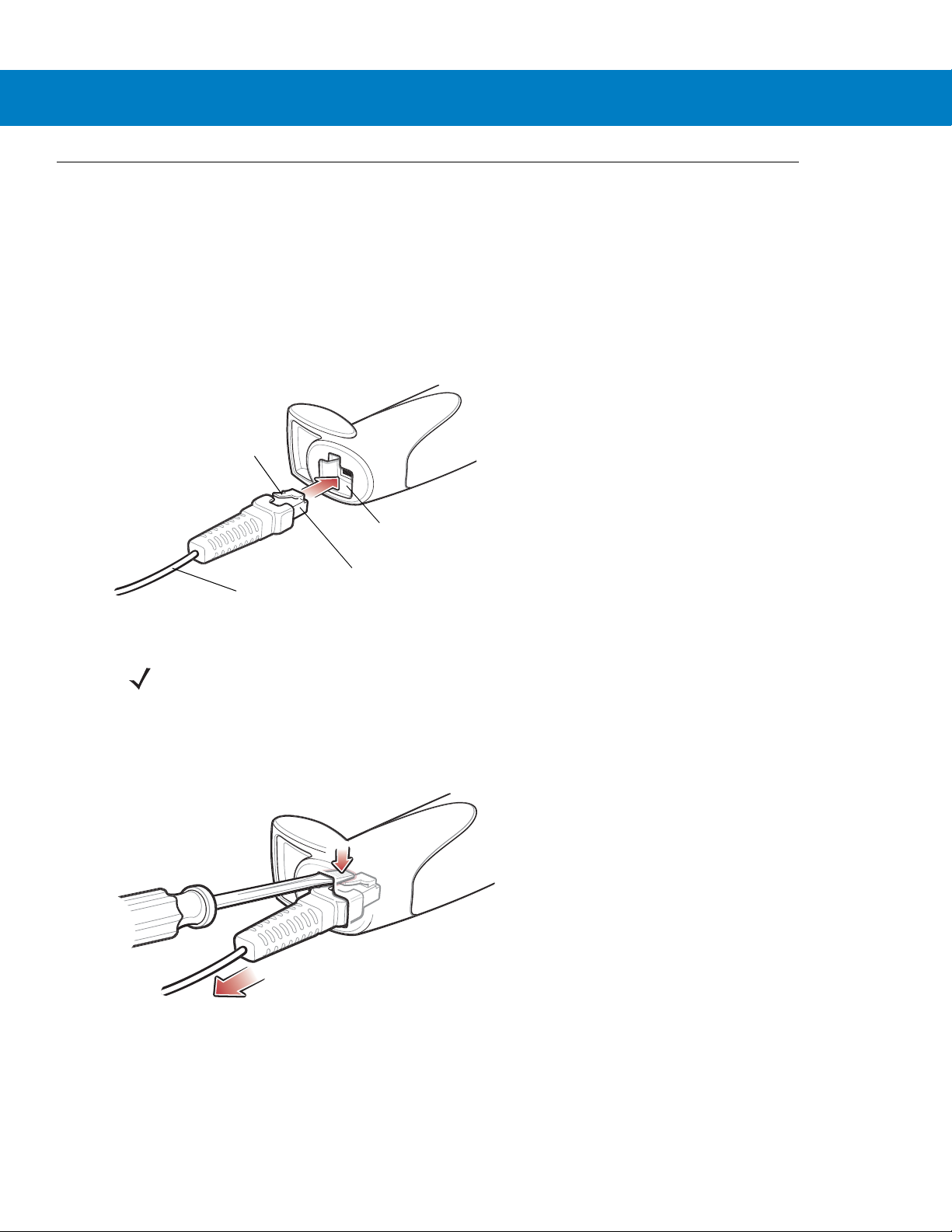
Clip
To host
Cable interface port
Interface cable modular
connector
Installing the Interface Cable
1. Plug the interface cable modular connector into the cable interface port on the bottom of the scanner handle
(see Figure 1-2).
2. Gently tug the cable to ensure the connector is secure.
3. Connect the other end of the interface cable to the host (see the specific host chapter for information on host
connections).
Getting Started 1 - 3
Figure 1-2
Installing the Cable
NOTE Different hosts require different cables. The connectors illustrated in each host chapter are examples only.
Connectors vary from those illustrated, but the steps to connect the digital scanner are the same.
Removing the Interface Cable
1. Using the tip of a screwdriver, depress the cable’s modular connector clip.
Figure 1-3
2. Carefully slide out the cable.
3. Follow the steps for Installing the Interface Cable to connect a new cable.
Removing the Cable
Page 24
1 - 4 Symbol DS6708 Digital Scanner Product Reference Guide
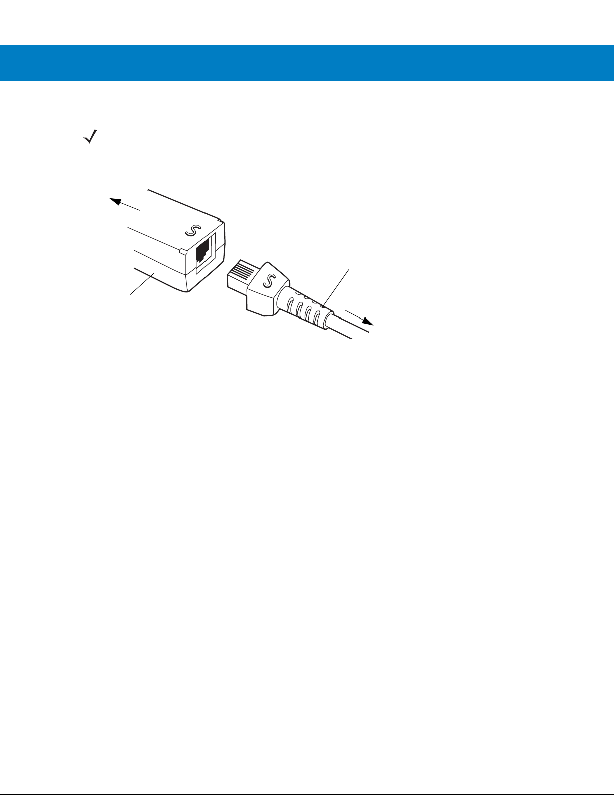
Synapse Adapter Cable
To digital scanner
Synapse
Smart Cable
To host
Connecting a Synapse Cable Interface (Symbol DS6708 0nly)
NOTE Refer to the Synapse Interface Guide provided with the Synapse cable for detailed setup instructions.
Synapse Smart Cables enable interfacing to a variety of hosts. The Synapse cable has built-in intelligence to
detect that host.
Figure 1-4
1. Plug the Synapse adapter cable (p/n 25-32463-xx) into the bottom of the digital scanner, as described in
Synapse Cable Connection
Installing the Interface Cable on page 1-3.
2. Align the ‘S’ on the Synapse adapter cable with the ‘S’ on the Synapse Smart Cable and plug the cable in.
3. Connect the other end of the Synapse Smart Cable to the host.
Connecting Power (if required)
If the host does not provide power to the digital scanner, connect an external power supply to the digital scanner:
1. Connect the interface cable to the bottom of the digital scanner, as described in Installing the Interface Cable
on page 1-3.
2. Connect the other end of the interface cable to the host (refer to the host manual to locate the correct port).
3. Plug the power supply into the power jack on the interface cable. Plug the other end of the power supp ly into
an AC outlet.
Configuring the Digital Scanner
To configure the digital scanner, use the bar codes included in this manual, or the 123Scan configuration program.
See Chapter 4, User Preferences & Miscellaneous Digital Scanner Options and Chapter 5, Decoding Preferences
for information about programming the digital scanner using bar code menus. Also see each host-specific chapter
to set up connection to a specific host type.
See Chapter 12, 123Scan to configure the digital scanner using this configuration program. The program includes
a help file.
Page 25
Mounting the Digital Scanner
Desk Mount
Use the optional desk mount for convenient and protective placement of the digital scanner on a flat surface.
Simply place the mount on the surface. The rubber feet hold the mount securely in place when inserting and
removing the digital scanner.
Getting Started 1 - 5
Figure 1-5
You can secure the desk mount to a desk surface by inserting two screws* appropriate for the mounting surface
through the screw holes of the desk mount, and into the surface. Screw the desk mount onto the surface with or
without the rubber feet.
*The recommended screws are two #6 screws (5/8” long).
Inserting the Digital Scanner in the Desk Mount
Wall Mount
To use the optional wall mount to mount the digital scanner on a wall, place the mount in the desired location on the
wall and secure by inserting two screws* appropriate for the mounting surface through the screw holes on the
mount, and into the surface. Insert the digital scanner into the mount as shown.
Figure 1-6
*The recommended screws are two #6 screws (1” long) and two #6 washers.
Securing the Wall Mount
Page 26
1 - 6 Symbol DS6708 Digital Scanner Product Reference Guide
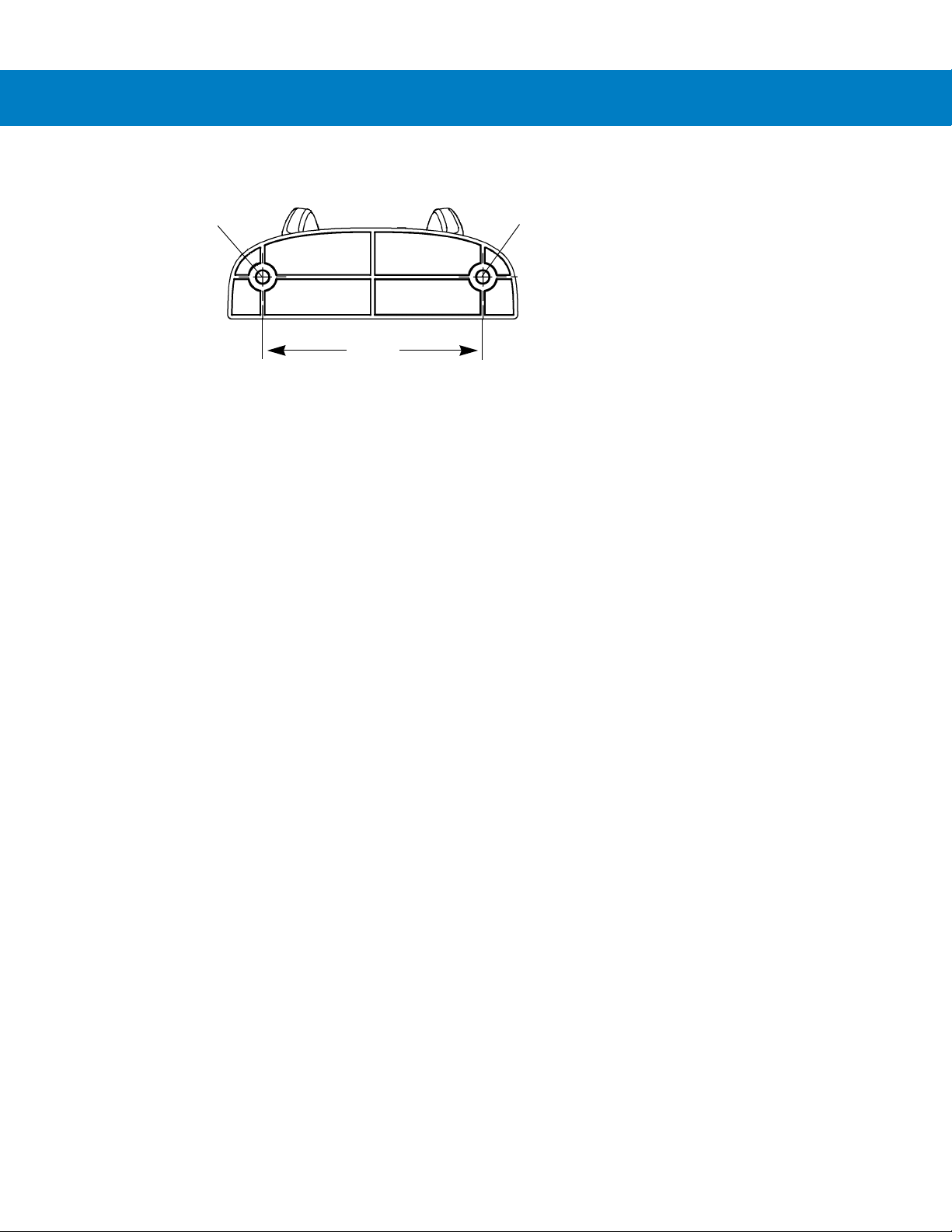
2.98”
Insert mounting
screw
Insert mounting
screw
For convenience, print this page and use the template below for mounting hole locations.
Figure 1-7
Wall Mounting Template
Page 27
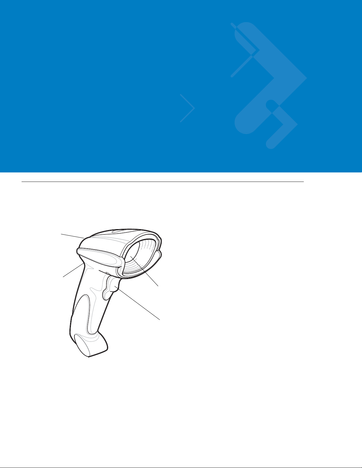
Chapter 2 Scanning
Scan
Window
Trigger
LED
Beeper
Introduction
This chapter provides beeper and LED definitions, techniqu es involved in scanning bar codes, general instructions
and tips about scanning, and decode zone diagrams.
Figure 2-8
Parts
Page 28
2 - 2 Symbol DS6708 Digital Scanner Product Reference Guide
Beeper Definitions
The digital scanner issues different beep sequences and patterns to indicate status. Table 2-1 defines beep
sequences that occur during both normal scanning and while programming the digital scanner.
Table 2-1
Standard Use
Low/medium/high beeps Power up.
Short high beep A bar code symbol was decoded (if decode beeper is enabled).
4 long low beeps A transmission error was detected in a scanned symbol. The data is ignored. This
5 low beeps Conversion or format error.
Low/high/low beeps ADF transmit error. See
High/high/high/low beeps RS-232 receive error.
Parameter Menu Scanning
Low/high/low/high beeps Out of host parameter storage space. Scan
Short high beep Correct entry scanned or correct menu sequence performed.
Low/high beeps Input error; incorrect bar code, progr amming sequence, or
High/low beeps Keyboard parameter selected. Enter value using numeric bar codes.
Beeper Definitions
Beeper Sequence Indication
occurs if the digital scanner is not properly configured. Check option setting.
Chapter 15, Advanced Data Formatting
remain in ADF program mode.
.
Set Default Parameter on page 4-4
Cancel
scanned;
.
High/low/high/low beeps Successful program exit with change in parameter setting.
Code 39 Buffering
High/low beeps New Code 39 data was entered into the buffer.
3 long high beeps Code 39 buffer is full.
Low/high/low beeps The Code 39 buffer was erased or there was an attempt to clear or transmit an
empty buffer.
Low/high beeps A successful transmission of buffered data.
Macro PDF
2 long low beeps
3 long low beeps Out of memory. There is not enough buffer space to store the current MPDF
4 long low beeps Bad symbology. Scanned a 1D or 2D bar code in a MPDF sequence, a duplicate
5 long low beeps Flushing MPDF buffer.
File ID error. A bar code not in the current MPDF sequence was scanned.
symbol.
MPDF label, a label in an incorrect order, or trying to transmit an empty or illegal
MPDF field.
Page 29

Scanning 2 - 3
Table 2-1
Fast warble beep Aborting MPDF sequence.
Low/high beeps Flushing an already empty MPDF buffer.
ADF Programming: Normal Data Entry. Duration of tones are short.
High/low beeps Enter another digit. Add leading zeros to the front if necessary.
Low/low beeps Enter another alphabetic character or scan the
High/high beeps Enter another criterion or action, or scan the
High/low/high/low beeps Rule saved. Rule entry mode exited.
High/low/low beeps All criteria or actions cleared for current rule, continue entering rule.
Low beep Delete last saved rule. The current rule is left intact.
Low/high/high beeps All rules are deleted.
ADF Programming: Error Indications. Duration of tones are very long.
Low/high/low/high beeps Out of rule memory. Erase some existing ru les, then try to save rule again. (It is no t
Beeper Definitions (Continued)
Beeper Sequence Indication
necessary to re-enter the current rule.)
End of Message
Save Rule
bar code.
bar code.
Low/high/low beeps Cancel rule entry. Rule entry mod e exited because of an error or the user asked to
exit rule entry .
Low/high beeps Entry error, wrong bar code scanned. Re-enter criterion or action. All previously
entered criteria and actions are retained. Criteria or action list is too long for a rule.
Host Specific
USB only
4 short high beeps Digital scanner has not completed initialization. Wait several seconds and scan
again.
Low/medium/high beeps
upon scanning a USB device
type
Low/medium/high beeps
occur more than once.
RS-232 only
1 short high beep A <BEL> character is received and Beep on <BEL> is enabled.
Communication with the bus must be established before the digital scanner can
operate at the highest power level.
The USB bus can put the digital scanner in a state where power to the digital
scanner is cycled on and off more than once. This is normal and usually happens
when the PC cold boots.
Page 30
2 - 4 Symbol DS6708 Digital Scanner Product Reference Guide
LED Definitions
In addition to beep sequences, the digital scanner uses a two-color LED to indicate st atus. Table 2-2 defines LED
colors that display during scanning.
Table 2-2
Off No power is applied to the digital scanner, or the digital scanner is on and ready to scan.
Green A bar code was successfully decoded.
Red A data transmission error or digital scanner malfunction occurred.
Standard LED Definitions
LED Indication
Scanning in Hand-Held Mode
Install and program the digital scanner (see Setting Up the Digital Scanner on page 1-3). For assistance, contact
the local supplier or Motorola Enterprise Mobility Support.
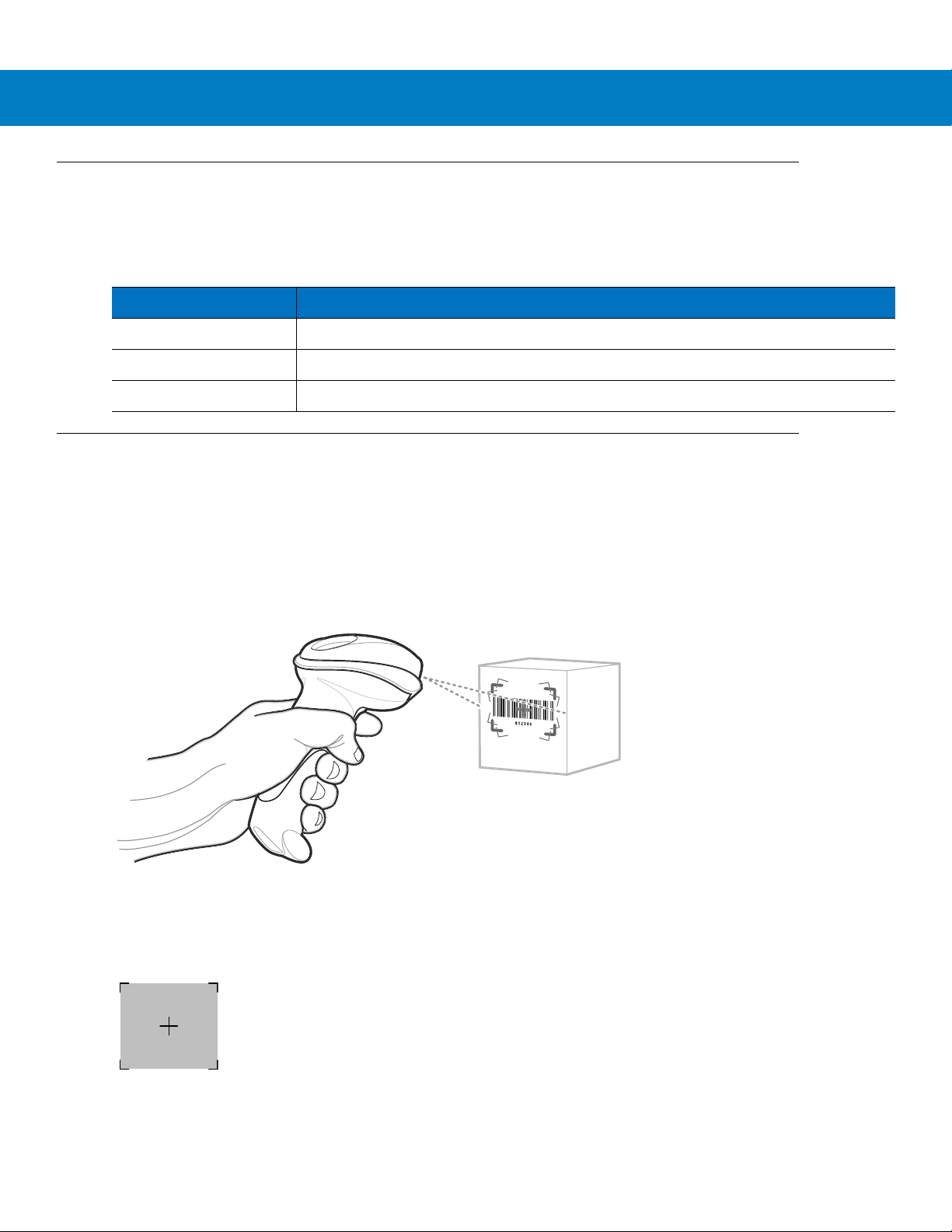
Scanning with the Digital Scanner
1. Ensure all connections are secure (see the appropriate host chapter.)
2. Aim the digital scanner at the bar code.
Figure 2-9
3. When the digital scanner senses movement, in its default Auto Aim trigger mode, it projects a red laser aiming
pattern which allows positioning the bar code or object within the field of view. (To turn of f the default Auto Aim
trigger mode, see Trigger Mode on page 4-8.)
Figure 2-10
If necessary, the digital scanner turns on its red LEDs to illuminate the target bar code.
Scanning in Hand-Held Mode
Laser Aiming Pattern
Page 31

Scanning 2 - 5
Linear bar code
PDF417 symbol
Symbol
Aiming Pattern
1D bar code
2D bar code
012345
012345
012345
012345
4. Center the symbol in any orientation within the aiming pattern. Be sure the entire symbol is within the
rectangular area formed by the brackets in the pattern.
Figure 2-11
Centering Symbol in Aiming Pattern
5. Hold the trigger until the digital scanner beeps, indicating the bar co de is successfully decoded. For more
information on beeper and LED definitions, see Table 2-1 and Table 2-2.
This process usually occurs instantaneo usly. Steps 2 - 4 are repeated on poor quality or dif ficult bar code s, until the
bar code decodes, you release the trigger, or the Decode Session Timeout occurs.
Aiming
Hold the digital scanner between two and nine inches (depending on symbol density; see Decode Zones on page
2-7) from the symbol, centering the aiming pattern cross hairs on the symbol.
The aiming pattern is smaller when the digital scanner is closer to the symbol an d larger when it is farthe r from the
symbol. Scan symbols with smaller bars or elements (mil size) closer to the digital scanner, and those with larger
bars or elements (mil size) farther from the digital scanner.
The digital scanner can also read a bar code presented within the aiming pattern but not centered. The top
examples in Figure 2-12 show acceptable aiming options, while the bottom examples can not be decoded.
Figure 2-12
Acceptable and Incorrect Aiming
Page 32

2 - 6 Symbol DS6708 Digital Scanner Product Reference Guide
Scanner
Holder (Cup)
Angle Adjustment Knob
Height Adjustment Knob
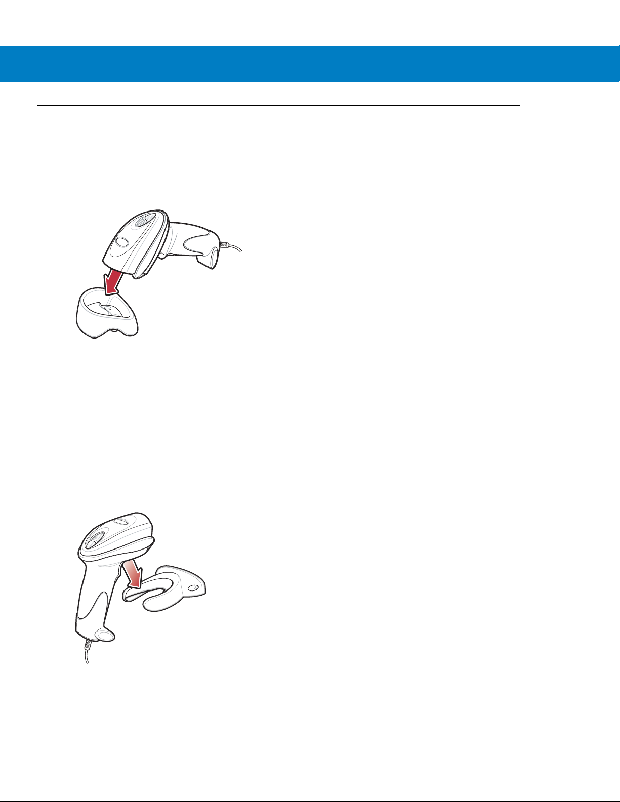
Scanning in Presentation Mode
The optional Intellistand adds greater flexibility to scanning operation. When you place the digital scanner in the
stand’s “cup,” the digital scanner’s built-in sensor places the digital scanner in presentation mode. When you
remove the digital scanner from the stand it operates in its normal hand-held mode.
Figure 2-13
Inserting the Digital Scanner in the Intellistand
To operate the digital scanner in the IntelliStand:
1. Connect the digital scanner to the host (see the appropriate host chapter for information on host connections).
2. Insert the digital scanner in the Intellistand by placing the front of the digital scanner into the stand’s “cup” (see
Figure 2-13).
3. Use the Intellistand’s adjustment knobs to adjust the height and angle of the digital scanner.
4. Center the symbol in the aiming pattern. The entire symbol must be within the brackets.
5. Upon successful decode, the digital scanner beeps and the LED turns green. For more information on beeper
and LED definitions, see Table 2-1 and Table 2-2.
Page 33
Decode Zones
In .
cm
0
0
DS6708
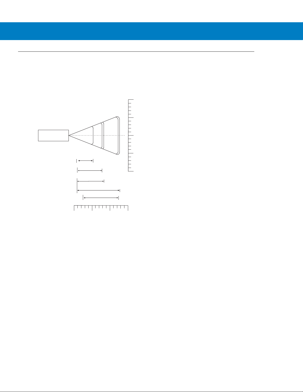
5 mil (Code 39)
5.4
13 mil (100% UPC/EAN)
8.4
12.9
0
5
5
In .
cm
W
i
d
t
h
o
f
F
i
e
l
d
10
10
0
12.7
12.7
25.4
31.6
0.9
20 mil (Code 39)
Note: Typical performance at 73.4 F (23 C)
on high quality symbols.
Depth of Field
5
12.7
10
25.41538.1
0.9
0.9
OO
Postnet
12.5
2.6
10 mil I 2 of 5
7.9
1.0
Scanning 2 - 7
Figure 2-14
Symbol DS6708 Digital Scanner Decode Zone for 1D Bar Codes
Page 34
2 - 8 Symbol DS6708 Digital Scanner Product Reference Guide
In .
cm
0
0
6.2
7.50
0
5
5
In .
cm
W
i
d
t
h
o
f
F
i
e
l
d
10
10
0
12.7
12.7
25.4
31.6
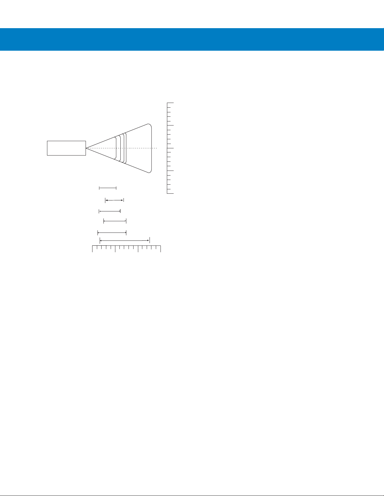
PDF417 (10 mil)
Datamatrix (10 mil)
Note: Typical performance at 73.4 F (23 C)
on high quality symbols.
Depth of Field
5
12.7
10
25.41538.1
OO
1.4
1.10
35 mil Maxicode
12.8
1.5
10 mil MicroPDF
7.50
2.3
10 mil QR Code
6.6 mil PDF417
2.6
6.8
1.4
5.2
DS6708
Figure 2-15
Symbol DS6708 Digital Scanner Decode Zone for 2D Bar Codes
Page 35

Chapter 3 Maintenance & Technical
Specifications
Introduction
This chapter provides suggested scanner maintenance, troubleshooting, technical specifications, and signal
descriptions (pinouts).
Maintenance
Cleaning the scan window is the only maintenance required. A dirty window can affect scanning accuracy.
•
Do not allow abrasive material to touch the window.
•
Remove any dirt particles with a damp cloth.
•
Wipe the window using a tissue moistened with ammonia/water.
•
Do not spray water or other cleaning liquids directly into the window.
Page 36

3 - 2 Symbol DS6708 Digital Scanner Product Reference Guide
Troubleshooting
Table 3-1
The aiming pattern does not
appear when pressing the
trigger.
Scanner emits short low/short
medium/short high beep
sequence (power-up beep
sequence) more than once.
Troubleshooting
Problem Possible Causes Possible Solutions
No power to the digital scanner. If the configuration requires a power
supply, re-connect the power supply.
Incorrect host interface cable is used. Connect the correct host interface
cable.
Interface/power cables are loose. Re-connect cables.
Digital scanner is disabled. For Synapse or IBM 468x mode,
enable the digital scanner via the host
interface. Otherwise, see the technical
person in charge of scanning.
If using RS-232 Nixdorf B mode, CTS
is not asserted.
Aiming pattern is disabled. Enable the aiming pattern. See
The USB bus may put the digital
scanner in a state where power to the
digital scanner is cycled on and off
more than once.
Assert CTS line.
Aiming Pattern on page 5-5
Normal during host reset.
Decode
.
Digital scanner emits aiming
pattern, but does not decode the
bar code.
Digital scanner emits 4 short
high beeps during decode
attempt.
Digital scanner is not programmed for
the correct bar code type.
Bar code symbol is unreadable. Scan test symbols of the same bar
The symbol is not completely inside
aiming pattern.
Digital scanner has not completed
USB initialization.
Program the digital scanner to read that
type of bar code. See
Symbologies
code type to determine if the bar code
is defaced.
Move the symbol completely within the
aiming pattern.
Wait several seconds and scan again.
.
Chapter 13,
Page 37

Maintenance & Technical Specifications 3 - 3
Table 3-1
Digital scanner decodes bar
code, but does not transmit the
data to the host.
Host displays scanned data
incorrectly.
Troubleshooting (Continued)
Problem Possible Causes Possible Solutions
Digital scanner is not programmed for
the correct host type.
Interface cable is loose. Re-connect the cable.
If 4 long low beeps are heard, a
transmission error occurred.
If 5 low beeps are heard, a conversion
or format error occurred.
If low/high/low beeps are heard, an
invalid ADF rule is detected.
If high/low beeps are heard, the digital
scanner is buffering Code 39 data.
Digital scanner is not programmed to
work with the host.
Scan the appropriate host type
programming bar code. See the
chapter corresponding to the host type.
Set the digital scanner's
communication parameters to match
the host's setting.
Configure the digital scanner's
conversion parameters properly.
Program the correct ADF rules.
Normal scanning a Code 39 bar code
and the Code 39 Buffering option is
enabled.
Scan the appropriate host type
programming bar code.
For RS-232, set the digital scanner's
communication parameters to match
the host's settings.
Digital scanner emits
high/high/high/low beeps when
not in use.
Digital scanner emits low/high
beeps during programming.
Digital scanner emits
low/high/low/high beeps during
programming.
For a Keyboard Wedge configuration,
program the system for the correct
keyboard type, and turn off the CAPS
LOCK key.
Program the proper editing options
(e.g., UPC-E to UPC-A Conversion).
RS-232 receive error. Normal during host reset. Otherwise,
set the digital scanner's RS-232 parity
to match the host setting.
Input error or
scanned.
Out of ADF parameter storage space. Erase all rules and re-program with
The digital scanner may be out of
Synapse parameter storage space.
Cancel
bar code was
Scan the correct numeric bar codes
within range for the parameter
programmed.
shorter rules.
Scan
Set Synapse Defaults
for cables no longer in use and
re-program the digital scanner for the
current host interface.
bar code
Page 38

3 - 4 Symbol DS6708 Digital Scanner Product Reference Guide
Table 3-1
Troubleshooting (Continued)
Problem Possible Causes Possible Solutions
Digital scanner emits
low/high/low beeps.
Digital scanner emits a
power-up beep after changing
USB host type.
Digital scanner emits one high
beep when not in use.
NOTE If after performing these checks the digital scanner still experiences problems, contact the distributor or
call Motorola Enterprise Mobility Support. See page xvii for the telephone numbers.
Clearing Code 39 buffer. Normal when scanning the Code 39
Buffering
Clear Buffer
bar code or
upon attempt to transmit an empty
Code 39 buffer.
The USB bus re-established power to
Normal when changing USB host type.
the digital scanner.
In RS-232 mode, a <BEL> character
was received and Beep on <BEL>
option is enabled.
Normal when
Beep on <BEL>
is
enabled and the digital scanner is in
RS-232 mode.
Page 39

Technical Specifications
Maintenance & Technical Specifications 3 - 5
Table 3-2
Physical Characteristi cs
Dimensions 6.55 in. x 4.72 in. x 2.82 in. (16.6 cm x 11.9 cm x 7.1 cm)
Weight: 6.4 oz. (182 gm)
Voltage & Current: 5 +/-10%VDC @ 350 mA
Color Cash Register White or Twilight Black
Performance Characteristics
Light Source Aiming: 650 nm laser diode
Field of View
(Vertical x Horizontal)
Roll
Pitch
Yaw
Symbology Decode Capability
Technical Specifications
Item Description
(H x L x W)
Illumination: 630 nm LED
34º (V) x 43º (H)
360º
+/- 65º
+/- 60º
1D UPC/EAN and with supplementals, Code 39, Code 39 Full ASCII, Tri- optic Code 39,
GS1 DataBar Variants (formerly RSS), GS1-128 (formerly UCC/EAN-128), Code
128, Code 128 Full ASCII, Code 93, Codabar (NW1), Interleaved 2 of 5, Discrete 2
of 5, MSI, Code 11, IATA, Bookland EAN, Code 32
PDF417 (& Variants) PDF417, MicroPDF417, Composite Codes
Postal U.S. Postnet and Planet, U.K., Japan, Australian, Dutch, 4State Postal
2D MaxiCode, Data Matrix (ECC 200), QR Code, Micro QR, Aztec
Typical Working Distance 5 mil (Code 39): 0.9 - 5.4 in. (2.3 - 13.7 cm)
10 mil (I 2 of 5): 1.0 - 7.9 in. (2.5 - 20.1 cm)
13 mil (100% UPC/EAN): 0.9 - 8.4 in. (2.3 - 21.3 cm)
Postnet 2.6 - 12.5 in. (6.6 - 31.8 cm)
20 mil (Code 39): 0.9 - 12.9 in. (2.3 - 32.8 cm)
PDF417 (6.6 Mil): 3.4 - 5.7 in. (8.6 - 14.5 cm)
QR Code (10 Mil) 2.6 - 6.8 in. (6.6 - 17.3 cm)
PDF417 (10 Mil): 1.4 - 6.2 in. (3.6 - 15.7 cm)
MicroPDF (10 Mil) 2.3 - 7.5 in. (5.8 - 19.1 cm)
Data Matrix (10 Mil): 1.1 - 7.5 in. (2.8 - 19.1 cm)
Maxicode (35 Mil): 1.5 - 12.8 in. (3.8 - 32.5 cm)
Page 40

3 - 6 Symbol DS6708 Digital Scanner Product Reference Guide
Table 3-2
Print Contrast 25% minimum reflectance
Motion Tolerances Horizontal Velocity: 5 in. (12.7 cm) per second
Interfaces Supported RS-232C (Standard, Nixdorf, ICL, & Fujitsu); USB (Standard, IBM SurePOS,
User Environment
Operating Temperature 32º F to 104º F (0º C to 40º C)
Storage Temperature -40º F to 158º F (-40º C to 70º C)
Humidity 5% to 95%, non-condensing
Drop Specifications Withstands multiple 5 ft. (1.52 m) drops to concrete at operating temperature
Ambient Light Immunity Immune to normal artificial indoor and natural outdoor (direct sunlight) lighting.
Regulatory
Electrical Safety UL6950-1, CSA C22.2 No. 60950-1, EN60950-1 / IEC60950-1
Technical Specifications (Continued)
Item Description
Macintosh); IBM 468x/469x; Keyboard Wedge; and, Synapse Connectivity allows
for connectivity to all of the above plus many non-standard interfaces.
extremes, and multiple 6 ft. (1.8 m) drops to concrete at room temperature (23º C).
Laser Safety EN60825-1:1994 +A1: 2002 +A2 :2001, IEC60825-1, 21CFR1040.10 and
21CFR1040.11, CDRH Class II, IEC Class 2
EMI/RFI FCC Part 15 Class B, ICES-003 Class B, CISPR 22, CISPR 24
Medical Electrical Equipment: EN60601-1-2: 2002
RoHS Compliance with RoHS Directive 2002/95/EEC
Mounting Options
(Accessories)
Power Supplies Power supplies are avail able for applications that do not supply po wer over the host
Intellistand with adjustable height: 5-10 in. (12.7-25.4 cm) and
adjustable angle: 0º - 90º
Desktop & Wall-mount holders are also available.
cable.
Page 41

Digital Scanner Signal Descriptions
Pin 10
Bottom of digital scanner
Pin 1
Interface cable
modular connector
Cable interface port
Maintenance & Technical Specifications 3 - 7
Figure 3-1
The signal descriptions in Table 3-3 apply to the connectors on the Symbol DS6708 dig ital scanner and are for
reference only.
Table 3-3
Pin IBM Synapse RS-232
1
2
3
4
5
6
7
8
9
10
Digital Scanner Cable Pinouts
Symbol DS6708 Digital Scanner Signal Pin-outs
Keyboard
Wedge
Reserved SynClock Reserved Reserved Reserved Jump to Pin 6 DBP
Power Power Power Power Power Power Power
Ground Ground Ground Ground Ground Ground Ground
IBM_A(+) Reserved TxD KeyClock DBP Reserved SOS
Reserved Reserved RxD TermData CTS D + Decode
IBM_B(-) SynData RTS KeyData RTS Jump to Pin 1 Trigger
Reserved Reserved CTS TermClock Reserved D - Enable
Reserved Reserved Reserved Reserved Reserved Reserved Reserved
Reserved Reserved Reserved Reserved Reserved Reserved Reserved
Reserved Reserved Reserved Reserved Reserved Reserved Reserved
Wand USB
Scanner
Emulation
Page 42

3 - 8 Symbol DS6708 Digital Scanner Product Reference Guide
Page 43

Chapter 4 User Preferences & Miscellaneous
*High Volume
(00h)
Feature/Option
* Indicates Default
Option Hex Value for
programming via SSI
command
Digital Scanner Options
Introduction
You can program the digital scanner to perform various functions, or activate different features. This chapter
describes each user preference feature and provides programming bar codes for selecting these features.
The digital scanner ships with the settings sho wn in Table 4-1 on page 4-2 (also see Appendix A, Standard Default
Parameters for all host device and miscellaneous defaults). If the default values suit requirement s, progr amming is
not necessary.
To set feature values, scan a single bar code or a short bar code sequence. The settings are stored in non-volatile
memory and are preserved even when the dig i tal scanner is pow er ed dow n.
NOTE Most computer monitors allow scanning the bar codes directly on the screen. When scanning from the
screen, be sure to set the document magnification to a level where you can see the bar code clearly, and
bars and/or spaces are not merging.
If not using a USB cable or Synapse cable, select a host type (see each host chapter for specific host information)
after the power-up beeps sound. This is only necessary upon the first power-up when connected to a new host.
To return all features to default values, scan the Set Default Parameter on page 4-4. Throughout the programmin g
bar code menus, asterisks indicate (
*)default values.
Page 44

4 - 2 Symbol DS6708 Digital Scanner Product Reference Guide
Scanning Sequence Examples
In most cases, scanning one bar code sets the parameter value. For example, to set the beeper tone to high, scan
the High Frequency (beeper tone) bar code listed under Beeper Tone on page 4-5. The digital scanner issues a
fast warble beep and the LED turns green, signifying a successful parameter entry.
Other parameters, such as Serial Response Time-Out or Data Transmission Format s, re quire scanning several
bar codes. See these parameter descriptions for this procedure.
Errors While Scanning
Unless otherwise specified, to correct an error during a scanning sequence, just re-scan the correct parameter.
User Preferences/Miscellaneous Options Parameter Defaults
Table 4-1 lists defaults for user preferences parameters. There are two ways to change the default values:
•
Scan the appropriate bar codes in this guide. The s e new values replace the standard default values in
memory. To recall the default parameter values, scan the Set Default Parameter on page 4-4.
•
Configure the digital scanner using the 123Scan configuration program (see Chapter 12, 123Scan).
NOTE See Appendix A, Standard Default Parameters for all user preferences, hosts, symbologies, and
miscellaneous default parameters.
Table 4-1
User Preferences
Set Default Parameter All Defaults 4-4
Parameter Scanning ECh Enable 4-4
Beeper Tone 91h Medium 4-5
Beeper Volume 8Ch High 4-6
Power Mode 80h Continuous On 4-6
Time Delay to Low Power Mode 92h 1 Minute 4-7
User Preferences Parameter Defaults
Parameter
Parameter
Number
Default
Page
Number
Trigger Mode 8Ah Auto Aim 4-8
Picklist Mode F0h 92h Disabled Always 4-9
Decode Session Timeout 88h 9.9 Sec 4-10
Timeout Between Decodes, Same Symbol 89h 0.6 Sec 4-10
Beep After Good Decode 38h Enable 4-11
Page 45

User Preferences & Miscellaneous Digital Scanner Options 4 - 3
Table 4-1
Fuzzy 1D Processing F1h, 02h Enable 4-11
Decode Mirror Images F1h, 19h Never 4-12
Miscellaneous Options
Transmit Code ID Character 2Dh None 4-13
Prefix Value 63h, 69h 7013 <CR><LF> 4-14
Suffix 1 Value
Suffix 2 Value
Scan Data Transmission Format EBh Data as is 4-15
FN1 Substitution Values 67h, 6Dh Set 4-16
Transmit “No Read” Message 5Eh Disable 4-17
Synapse Interface F0h, ACh Standard Synapse
User Preferences Parameter Defaults (Continued)
Parameter
Parameter
Number
62h, 68h
64h, 6Ah
Default
7013 <CR><LF> 4-14
4-17
Connection
Page
Number
Page 46

4 - 4 Symbol DS6708 Digital Scanner Product Reference Guide
User Preferences
Set Default Parameter
Scan this bar code to return all parameters to the default values listed in Table A-1 on page A-1.
*Set All Defaults
Parameter Scanning
Parameter # ECh
To disable decoding of parameter bar codes, scan the Disable Parameter Scanning bar code be low . Note that the
scanner can still decode the Set Defaults parameter bar code. To enable decoding of parameter bar codes, ei ther
scan Enable Parameter Scanning or Set All Defaults.
*Enable Parameter Scanning
(01h)
Disable Parameter Scanning
(00h)
Page 47

User Preferences & Miscellaneous Digital Scanner Options 4 - 5
Beeper Tone
Parameter # 91h
To select a decode beep frequency (tone), scan the Low Frequency, Medium Frequency, or High Frequency bar
code.
Low Frequency
(02h)
*Medium Frequency
(Optimum Setting)
(01h)
High Frequency
(00h)
Page 48

4 - 6 Symbol DS6708 Digital Scanner Product Reference Guide
Beeper Volume
Parameter # 8Ch
To select a beeper volume, scan the Low Volume, Medium Volume, or High Volume bar code.
Low Volume
(02h)
Medium Volume
(01h)
*High Volume
(00h)
Power Mode
Parameter # 80h
This parameter determines whether or not p ower remains on af ter a decode attemp t. In reduced power mode, the
digital scanner enters into a low power consumption mode to preserve battery life after each decode attempt. In
continuous power mode, power remains on after each decode attempt.
*Continuous On
(00h)
Reduced Power Mode
(01h)
Page 49
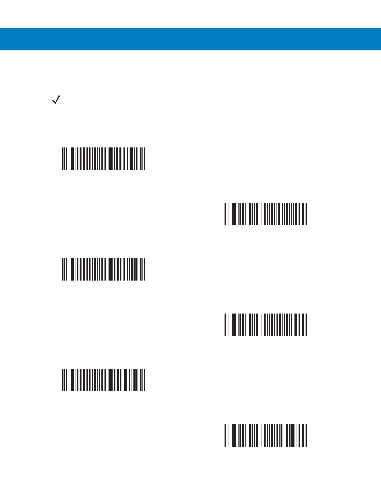
User Preferences & Miscellaneous Digital Scanner Options 4 - 7
Time Delay to Low Power Mode
Parameter # 92h
NOTE This parameter only applies when Power Mode is set to Reduced Power.
This parameter sets the time the digital scanner remains active after decoding. The digital scanner wakes upon
trigger pull or when the host attempts to communicate with the digital scanner.
1 Second
(11h)
*1 Minute
(21h)
15 Minutes
(2Bh)
5 Seconds
(15h)
5 Minutes
(25h)
1 Hour
(31h)
Page 50

4 - 8 Symbol DS6708 Digital Scanner Product Reference Guide
Trigger Mode
Parameter # 8Ah
Select one of the following trigger modes for the digital scanner:
•
Level - A trigger pull activates decode processing. Decode processing continues until the bar code decodes,
you release the trigger , or the Decod e Session Timeout occurs.
•
Blink - This trigger mode is used in presentation (scanstand) mode. The digital scanner activates decode
processing when it detects a bar code in its field of view. Decoding range is reduced in this mode.
•
Auto Aim - This trigger mode turns on the red laser aiming pattern when the digital scanner senses motion.
A trigger pull activates decode processing. After 2 seconds of inactivity the red laser aiming pattern
automatically shuts off.
Level
(00h)
*Auto Aim
(09h)
Blink
(07h)
Page 51

User Preferences & Miscellaneous Digital Scanner Options 4 - 9
Picklist Mode
Parameter # F0h 92h
Picklist mode enables the digital scanner to decode only bar codes that are aligned under the laser crosshair.
Select one of the following picklist modes for the digital scanner:
•
Disabled Always - Picklist mode is always disabled.
•
Enabled Out of Scanstand - Picklist mode is enabled when the digital scanner is out of presentation mode
and disabled when the digital scanner is in presentation mode.
•
Enabled Always - Picklist mode is always enabled.
*Disabled Always
(00h)
Enabled Always
(02h)
Enabled Out of Scanstand
(01h)
Page 52

4 - 10 Symbol DS6708 Digital Scanner Product Reference Guide
Decode Session Timeout
Parameter # 88h
This parameter sets the maximum time decode processing continues during a scan attempt. It is programmable in
0.1 second increments from 0.5 to 9.9 seconds. The default timeout is 9.9 seconds.
To set a Decode Session Timeout, scan the bar code below. Next, scan two numeric bar codes from Appendix D,
Numeric Bar Codes that correspond to the desired on time. Enter a leading zero for single digit numbers. For
example, to set a Decode Session Timeout of 0.5 seconds, scan the bar code below, then scan the 0 and 5 bar
codes. To correct an error or change the selection, scan Cancel on page D-2.
Decode Session Timeout
Timeout Between Decodes, Same Symbol
Parameter # 89h
Use this option in presentation (scanstand) mode to prevent the beeper from continuously beeping when a symbol
is left in the digital scanner’s field of view. It is programmable in 0.1 second increments from 0.0 to 9.9 seconds.
The default interval is 0.6 seconds.
To select the timeout between decodes for the same symbol, scan the bar code below, then scan two numeric bar
codes from Appendix D, Numeric Bar Codes that correspond to the desired interval, in 0.1 second increments.
Timeout Between Decodes, Same Symbol
Page 53

User Preferences & Miscellaneous Digital Scanner Options 4 - 11
Beep After Good Decode
Parameter # 38h
Scan a bar code below to select whether or not the digital scanner beeps after a good decode. If selecting Do Not
Beep After Good Decode, the beeper still operates during parameter menu scanning and to indicate error
conditions.
*Beep After Good Decode
(Enable)
(01h)
Do Not Beep After Good Decode
(Disable)
(00h)
Fuzzy 1D Processing
Parameter # F1h 02h
This option is enabled by default to optimize decode performance on 1D bar codes, including damaged and poor
quality symbols. Disable this only if you experience time delays w he n deco din g 2D bar codes, or in detecting a no
decode.
*Enable Fuzzy 1D Processing
(01h)
Disable Fuzzy 1D Processing
(00h)
Page 54

4 - 12 Symbol DS6708 Digital Scanner Product Reference Guide
Decode Mirror Images (Data Matrix Only)
Parameter # F1h 19h
Select an option for decoding mirror image Data Matrix bar codes:
•
Always - decode only Data Matrix bar codes that are mirror images
•
Never - do not decode Data Matrix bar codes that are mirror images
•
Auto - decode both mirrored and unmirrored Data Matrix bar codes.
*Never
(00h)
Auto
(02h)
Always
(01h)
Page 55

User Preferences & Miscellaneous Digital Scanner Options 4 - 13
Miscellaneous Scanner Parameters
Transmit Code ID Character
Parameter # 2Dh
A Code ID character identifies the code type of a scanned bar code. This is useful when decoding more than one
code type. In addition to any single character prefix already selected, the Code ID character is inserted between
the prefix and the decoded symbol.
Select no Code ID character, a Symbol Code ID character, or an AIM Code ID character. For Code ID Characters,
see Symbol Code Identifiers on page B-1 and AIM Code Identifiers on page B-3.
NOTE If you enable Symbol Code ID Character or AIM Code ID Character, and enable Transmit “No Read”
Message on page 4-17, the scanner appends the code ID for Code 39 to the NR message.
Symbol Code ID Character
(02h)
*None
(00h)
AIM Code ID Character
(01h)
Page 56
4 - 14 Symbol DS6708 Digital Scanner Product Reference Guide
Prefix/Suffix Values
Key Category Parameter # P = 63h, S1 = 62h, S2 = 64h
Decimal Value Parameter # P = 69h, S1 = 68h, S2 = 6Ah
You can append a prefix a nd/or one or two suffixes to scan data for use in data editing. To set a value for a prefix or
suffix, scan a four-digit number (i.e., fou r bar codes from Appendix D, Numeric Bar Codes) tha t corresponds to that
value. See Table E-1 on page E-1 for the four-digit codes.
When using host commands to set the prefix or suffix, set the key category parameter to 1, th en set the 3-digit
decimal value. See Table E-1 on page E-1 for the four-digit codes.
To correct an error or change a selection, scan Cancel on page D-2.
NOTE To use Prefix/Suffix values, first set the Scan Data Transmission Format on page 4-15.
Scan Prefix
(07h)
Scan Suffix 2
(08h)
Scan Suffix 1
(06h)
Data Format Cancel
Page 57
User Preferences & Miscellaneous Digital Scanner Options 4 - 15
Scan Data Transmission Format
Parameter # EBh
To change the scan data format, scan one of the following eight bar codes corresponding to the desired format.
NOTE If using this parameter do not use ADF rules to set the prefix/suffix.
To set values for the prefix and/or suffix, see Prefix/Suffix Values on page 4-14.
*Data As Is
(00h)
<DATA> <SUFFIX 2>
(02h)
<PREFIX> <DA TA >
(04h)
<DATA> <SUFFIX 1>
(01h)
<DATA> <SUFFIX 1> <SUFFIX 2>
(03h)
Page 58

4 - 16 Symbol DS6708 Digital Scanner Product Reference Guide
Scan Data Transmission Format (continued)
<PREFIX> <DA TA> <SUFFIX 2>
(06h)
<PREFIX> <DATA> <SUFFIX 1>
(05h)
<PREFIX> <DATA> <SUFFIX 1> <SUFFIX 2>
(07h)
FN1 Substitution Values
Key Category Parameter # 67h
Decimal Value Parameter # 6Dh
The Wedge and USB HID Keyboard hosts support a FN1 Substitution feature. Enabling this substitutes any FN1
character (0x1b) in an EAN128 bar code with a value. This value defaults to 7013 (Enter Key).
When using host commands to set the FN1 substitution value, set the key category parameter to 1, then set the
3-digit keystroke value. See the ASCII Character Set table for the current host interface for the desired value.
To select a FN1 substitution value via bar code menus:
1. Scan the bar code below.
Set FN1 Substitution Value
2. Locate the keystroke desired for FN1 Substitution in the ASCII Character Set table for the current host
interface. Enter the 4-digit ASCII Value by scanning each digit in Appendix D, Numeric Bar Codes.
To correct an error or change the selection, scan Cancel.
To enable FN1 substitution for USB HID keyboard, scan the Enable FN1 Substitution bar code on page 4-16.
Page 59

User Preferences & Miscellaneous Digital Scanner Options 4 - 17
Transmit “No Read” Message
Parameter # 5Eh
Scan a bar code below to select whether or not to transmit a No Read message. Enable this to transmit the
characters NR when a bar code does not decoded. Disable this to send nothing to the host if a symbol does not
decode.
NOTE If you enable Transmit No Read, and also enable Symbol Code ID Character or AIM Code ID Character
for Transmit Code ID Character on page 4-13, the scanner appends the code ID for Code 39 to the NR
message.
Enable No Read
(01h)
*Disable No Read
(00h)
Page 60

4 - 18 Symbol DS6708 Digital Scanner Product Reference Guide
Synapse Interface
Parameter # F0h, ACh
The auto-detection of a Synapse cable varies in duration depending on the type of Synapse connection. If you
connected a digital scanner to another scanner using a Synapse cable, use the Auxiliary Synapse Port connection.
In all other cases, when using the cable, the default setting is recommended.
To disconnect and reconnect the digital scanner from a Synapse cable that is connected to a live host via a
Synapse, use the "Plug and Play" setting. Do not change this setting from the default if an on-board wedge host is
enabled.
*Standard Synapse Connection
(01h)
“Plug and Play” Synapse Connecti on
(0Ah)
Auxiliary Synapse Port Connection
(32h)
Page 61

Chapter 5 Decoding Preferences
Feature/Option
* Indicates Default
*Enable Decode Aiming Pattern
(02h)
Option Hex Value
for programming
via SSI command
Introduction
You can program the digital scanner to perform various functions, or activate different features. This chapter
describes decoding preference features and provides programming bar codes for selecting these features.
The digital scanner ships with the settings shown in the Decoding Preferences Parameter Defaults on page 5-2
(also see Appendix A, Standard Default Parameters for all host device and miscellaneous defaults). If the default
values suit requirements, programming is not necessary.
To set feature values, scan a single bar code or a short bar code sequence. The settings are stored in non-volatile
memory and are preserved even when the dig i tal scanner is pow er ed dow n.
NOTE Most computer monitors allow scanning the bar codes directly on the screen. When scanning from the
screen, be sure to set the document magnification to a level where you can see the bar code clearly, and
bars and/or spaces are not merging.
If not using a USB cable, select a host type (see each host chapter for specific host information) afte r the power-up
beeps sound. This is only necessary upon the first power-up when connected to a new host.
To return all features to default values, scan the Set Default Parameter on page 4-4. Throughout the programmin g
bar code menus, asterisks (
*) indicate default values.
Page 62

5 - 2 Symbol DS6708 Digital Scanner Product Reference Guide
Scanning Sequence Examples
In most cases scanning one bar code sets the parameter value. For example, to disable the decode aim ing pattern,
scan the Disable Decode Aiming Pattern bar code listed under Decode Aiming Pattern on page 5-5. The digital
scanner issues a fast warble beep and the LED turns green, signifying a successful parameter entry.
Other parameters require scanning several bar codes. See these parameter descriptions for this procedure.
Errors While Scanning
Unless otherwise specified, to correct an error during a scanning sequence, just re-scan the correct parameter.
Decoding Preferences Parameter Defaults
Table 5-1 lists the defaults for decoding preferences parameters. There are two ways to change the default values:
•
Scan the appropriate bar codes in this guide. The s e new values replace the standard default values in
memory. To recall the default parameter values, scan the Set Default Parameter on page 4-4.
•
Configure the digital scanner using the 123Scan configuration program (see Chapter 12, 123Scan).
NOTE See Appendix A, Standard Default Parameters for all user preferences, hosts, symbologies, and
miscellaneous default parameters.
Table 5-1
Decoding Options
Decoding Illumination F0h 2Ah Enable 5-3
Illumination Bank Control F1h 3Bh Full Illumination 5-4
Decode Aiming Pattern F0h 32h Enable 5-5
Low Light Enhancement F1h 64h Disable 5-5
Presentation Mode Field of View F1h 61h Default (Reduced) 5-6
Decoding Preferences Parameter Defaults
Parameter
Parameter
Number
Default
Page
Number
Page 63

Decoding Preferences
The parameters in this chapter control bar code decoding characteristics.
Decoding Illumination
Parameter # F0h, 2Ah
Selecting Enable Decoding Illumination causes the digital scanner to flash illumination to aid decoding. Select
Disable Decoding Illumination to prevent the digital scanner from using decoding illumination.
Enabling illumination usually results in superior images. The effectiveness of the illumination decreases as the
distance to the target increases.
Decoding Preferences 5 - 3
*Enable Decoding Illumination
(01h)
Disable Decoding Illumination
(00h)
Page 64

5 - 4 Symbol DS6708 Digital Scanner Product Reference Guide
Illumination Bank Control
Parameter # F1h 3Bh
Select an illumination bank control parameter to control the illumination banks on the scan engine.
•
Full (0) (default): Enable the full illumination system.
•
Auto (1): The illumination system automatically switches from left to right banks.
•
Left (2): The left bank is enabled.
•
Right (3): The right bank is enabled.
*Full Illumination
(00h)
Left Illumination
(02h)
Auto Illumination
(01h)
Right Illumination
(03h)
Page 65
Decoding Preferences 5 - 5
Decode Aiming Pattern
Parameter # F0h, 32h
This parameter only applies in Decode Mode. Select Enable Decode Aiming Pattern to project the aiming pattern
during bar code capture, or Disable Decode Aiming Pattern to turn the aiming pattern off.
NOTE With Picklist Mode on page 4-9 enabled, the decode aiming pattern flashes even when the Decode
Aiming Pattern is disabled.
*Enable Decode Aiming Pattern
(02h)
Disable Decode Aiming Pattern
(00h)
Low Light Enhancement
Parameter # F1h, 64h
In Scanstand mode, selecting Enable Low Light Enhancem ent causes illumination to remain on at a low level in
low lighting conditions. Select Disable Low Light Enhancement to prevent illumination from remaining on under
these conditions.
Enable Low Light Enhancement
(01h)
*Disable Low Light Enhancement
(00h)
Page 66

5 - 6 Symbol DS6708 Digital Scanner Product Reference Guide
Presentation Mode Field of View
Parameter # F1h, 61h
In presentation mode, the digital scanner searches for a b ar code in a smaller region around the aiming pattern’s
center cross to speed search time.
To use a full field of view, scan Presentat ion Mode Full Field of V iew . This all ows the digital scanner to search the
larger area of the aiming pattern.
*Presentation Mode Default Field of View
(01h)
Presentation Mode Full Field of View
(02h)
Page 67

Chapter 6 USB Interface
*North American Standard USB Keyboard
Feature/Option
*Indicates Default
Introduction
This chapter describes how to set up the digital scanne r with a USB host. The d igital scanner connects dir ectly to a
USB host, or a powered USB hub, which powers it. No additional power supply is required.
Throughout the programming bar code menus, aste risks (
NOTE Most computer monitors allow scanning the bar codes directly on the screen. When scanning from the
screen, be sure to set the document magnification to a level where you can see the bar code clearly, and
bars and/or spaces are not merging.
*) indicate default values.
Page 68
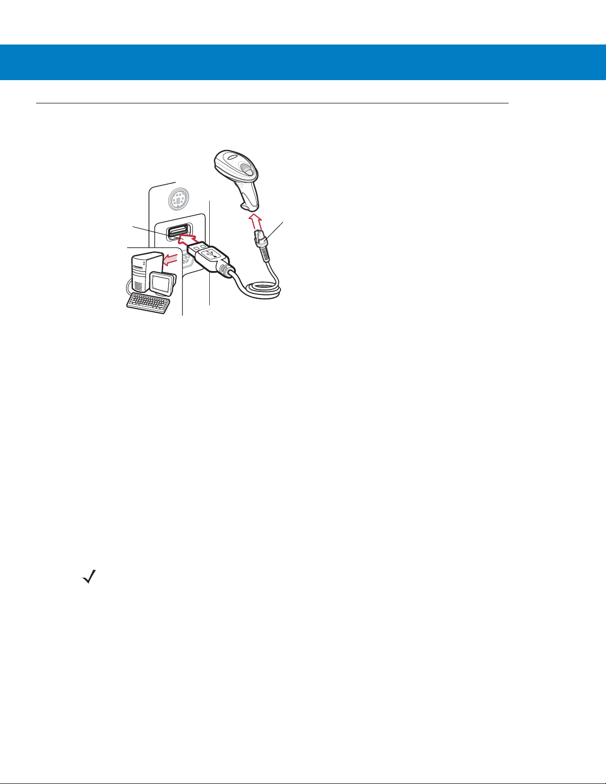
6 - 2 Symbol DS6708 Digital Scanner Product Reference Guide
USB Series A
Connector
Interface Cable
Connecting a USB Interface
Figure 6-1
The digital scanner connects with USB-capable hosts including:
•
•
The following operating systems support the digital scanner through USB:
•
•
•
The digital scanner also interfaces with other USB hosts which support USB Human Interface Devices (HID).
To set up the digital scanner:
1. Connect the modular connector of the USB interface cable to the cable interface port on the digital scanner
(see Installing the Interface Cable on page 1-3).
USB Connection
Desktop PCs and notebooks
• Apple™ iMac, G4, iBooks (North America only)
• IBM SurePOS terminals
Sun, IBM, and other network computers that support more than one keyboard.
Windows® 98, 2000, ME, XP
MacOS 8.5 - MacOS 10.3
IBM 4690 OS.
NOTE Interface cables vary depending on configuration. The connectors illustrated in Figure 6-1 are examples
only. The connectors may be different than those illustrated, but the steps to connect the scanner are the
same.
2. Plug the series A connector in the USB host or hub, or plug the Plus Power connector in an available port of
the IBM SurePOS terminal.
3. Select the USB device type by scanning the appropriate ba r cod e from USB Device Type on page 6-4.
4. On first installation when using Windows, the software prompts to select or install the Human Interface Device
driver. To install this driver, provided by Windows, click Next through all the choices and click Finished on the
last choice. The digital scanner powers up during this installation.
Page 69
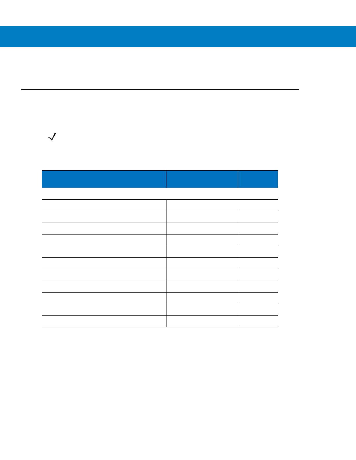
5. To modify any other parameter options, scan the appropriate bar codes in this chapter.
If problems occur with the system, see Troubleshooting on page 3-2.
USB Parameter Defaults
Table 6-1 lists the defaults for USB host parameters. To change any option, scan the appropriate bar code(s)
provided in the Parameter Descriptions section beginning on page 6-4.
NOTE See Appendix A, Standard Default Parameters for all user preferences, hosts, symbologies, and
miscellaneous default parameters.
USB Interface 6 - 3
Table 6-1
USB Host Parameters
USB Device Type HID Keyboard Emulation 6-4
USB Country Keyboard Types (Country Codes) North American 6-5
USB Keystroke Delay No Delay 6-7
USB CAPS Lock Override Disable 6-7
USB Ignore Unknown Characters Enable 6-8
Emulate Keypad Disable 6-8
Emulate Keypad with Leading Zero Disable 6-9
USB FN1 Substitution Disable 6-9
Function Key Mapping Disable 6-10
Simulated Caps Lock Disable 6-10
Convert Case None 6-11
USB Interface Parameter Defaults
Parameter Default
Page
Number
Page 70
6 - 4 Symbol DS6708 Digital Scanner Product Reference Guide
USB Host Parameters
USB Device Type
Select the desired USB device type.
NOTE When changing USB Device Types, the digital scanner automatically resets and issues the standard
startup beep sequences.
*HID Keyboard Emulation
IBM Hand-Held USB
Simple COM Port Emulation
IBM Table Top USB
USB OPOS Handheld
Page 71

USB Interface 6 - 5
USB Country Keyboard Types - Country Codes
Scan the bar code corresponding to the keyboard type. This setting applies only to the USB HID Keyboard
Emulation device.
NOTE When changing USB country keyboard types the digital scanner automatically resets and issues the
standard startup beep sequences.
*North American Standard USB Keyboard
French Windows
French Canadian Windows 2000/XP
German Windows
French Canadian Windows 95/98
Page 72
6 - 6 Symbol DS6708 Digital Scanner Product Reference Guide
USB Country Keyboard Types - Country Codes (continued)
Italian Windows
Spanish Windows
UK English Windows
Portuguese-Brazilian Windows
Swedish Windows
Japanese Windows (ASCII)
Page 73
USB Interface 6 - 7
USB Keystroke Delay
This parameter sets the delay, in milliseconds, between emulated keystrokes. Scan a bar code below to increase
the delay when hosts require a slower transmission of data.
*No Delay
Medium Delay (20 msec)
Long Delay (40 msec)
USB CAPS Lock Override
This option applies only to the HID Keyboard Emulation device. Enable this to preserve the case of the data
regardless of the state of the Caps Lock key. This setting is always enabled for the Japanese, Windows (ASCII)
keyboard type and can not be disabled.
Override Caps Lock Key
(Enable)
*Do Not Override Caps Lock Key
(Disable)
Page 74

6 - 8 Symbol DS6708 Digital Scanner Product Reference Guide
USB Ignore Unknown Characters
This option applies only to the HID Keyboard Emulation device and IBM device. Unknown characters are
characters the host does not recognize. Select Send Bar Codes W i th Unknown Chara ct ers to se nd a ll ba r cod e
data except for unknown characters. The digital scanner issues no error beeps.
Select Do Not Send Bar Codes With Unknown Characters, for IBM devices, to prevent sending bar codes
containing at least one unknown character are to the host, or for HID Keyboard Emulation devices, this sends the
bar code characters up to the unknown character. The digital scanner issues an error beep.
*Send Bar Codes with Unknown Characters
(Transmit)
Do Not Send Bar Codes with Unknown Characters
(Disable)
Emulate Keypad
Enable this to send all characters as ASCII sequences over the numeric keypad. For example ASCII A tran smits as
“ALT make” 0 6 5 “ALT Break”.
*Disable Keypad Emulation
Enable Keypad Emulation
Page 75

USB Interface 6 - 9
Emulate Keypad with Leading Zero
Enable this to send character sequences sent over the numeric keypad as ISO characters which have a leading
zero. For example ASCII A transmits as “ALT MAKE” 0 0 6 5 “ALT BREAK”.
*Disable Keypad Emulation with Leading Zero
Enable Keypad Emulation with Leading Zero
USB Keyboard FN 1 Substitution
This option applies only to the USB HID Keyboard Emulation device. Enable this to replace any FN 1 characters in
an EAN 128 bar code with a user-selected Key Category and value (see FN1 Substitution Values on page 4-16 to
set the Key Category and Key Value).
Enable
*Disable
Page 76

6 - 10 Symbol DS6708 Digital Scanner Product Reference Guide
Function Key Mapping
ASCII values under 32 are normally sent as a control-ke y se quen ce s (se e Table 6-2 on page 6-12). Enable this
parameter to send the keys in bold in place of the standard key mapping. Table entries that do not have a bold
entry remain the same whether or not you enable this parameter.
*Disable Function Key Mapping
Enable Function Key Mapping
Simulated Caps Lock
Enable this to invert upper and lower case characters on the bar code as if the Caps Lock state is enabled on the
keyboard. This inversion occurs regardless of the keyboard’s Caps Lock state.
*Disable Simulated Caps Lock
Enable Simulated Caps Lock
Page 77

Convert Case
Enable this to convert all bar code data to the selected case.
*No Case Conversion
USB Interface 6 - 11
Convert All to Upper Case
Convert All to Lower Case
Page 78

6 - 12 Symbol DS6708 Digital Scanner Product Reference Guide
ASCII Character Set for USB
Table 6-2
Prefix/ Suffix Value
USB Prefix/Suffix Values
Full ASCII Code 39
Encode Char.acter
1000 %U CTRL 2
1001 $A CTRL A
1002 $B CTRL B
1003 $C CTRL C
1004 $D CTRL D
1005 $E CTRL E
1006 $F CTRL F
1007 $G CTRL G
1008 $H
1009 $I
CTRL H/
CTRL I/
1010 $J CTRL J
1011 $K CTRL K
Keystroke
BACKSPACE
1
HORIZONTAL TAB
1
1012 $L CTRL L
1013 $M
CTRL M/
1014 $N CTRL N
1015 $O CTRL O
1016 $P CTRL P
1017 $Q CTRL Q
1018 $R CTRL R
1019 $S CTRL S
1020 $T CTRL T
1021 $U CTRL U
1022 $V CTRL V
1023 $W CTRL W
1024 $X CTRL X
1
The keystroke in bold transmits only if you enable
. Otherwise, the unbolded keystroke transmits.
6-10
Function Key Mapping on page
ENTER
1
Page 79

USB Interface 6 - 13
Table 6-2
Prefix/ Suffix Value
USB Prefix/Suffix Values (Continued)
Full ASCII Code 39
Encode Char.acter
1025 $Y CTRL Y
1026 $Z CTRL Z
1027 %A
CTRL [/
1028 %B CTRL \
1029 %C CTRL ]
1030 %D CTRL 6
1031 %E CTRL 1032 Space Space
1033 /A !
1034 /B “
1035 /C #
1036 /D $
Keystroke
1
ESC
1037 /E %
1038 /F &
1039 /G ‘
1040 /H (
1041 /I )
1042 /J *
1043 /K +
1044 /L ,
1045 - 1046 . .
1047 /O /
1048 0 0
1049 1 1
1050 2 2
1051 3 3
1052 4 4
1
The keystroke in bold transmits only if you enable
6-10
. Otherwise, the unbolded keystroke transmits.
Function Key Mapping on page
Page 80

6 - 14 Symbol DS6708 Digital Scanner Product Reference Guide
Table 6-2
Prefix/ Suffix Value
USB Prefix/Suffix Values (Continued)
Full ASCII Code 39
Encode Char.acter
1053 5 5
1054 6 6
1055 7 7
1056 8 8
1057 9 9
1058 /Z :
1059 %F ;
1060 %G <
1061 %H =
1062 %I >
1063 %J ?
1064 %V @
1065 A A
Keystroke
1066 B B
1067 C C
1068 D D
1069 E E
1070 F F
1071 G G
1072 H H
1073 I I
1074 J J
1075 K K
1076 L L
1077 M M
1078 N N
1079 O O
1080 P P
1
The keystroke in bold transmits only if you enable
6-10
. Otherwise, the unbolded keystroke transmits.
Function Key Mapping on page
Page 81

USB Interface 6 - 15
Table 6-2
Prefix/ Suffix Value
USB Prefix/Suffix Values (Continued)
Full ASCII Code 39
Encode Char.acter
1081 Q Q
1082 R R
1083 S S
1084 T T
1085 U U
1086 V V
1087 W W
1088 X X
1089 Y Y
1090 Z Z
1091 %K [
1092 %L \
1093 %M ]
Keystroke
1094 %N ^
1095 %O _
1096 %W `
1097 +A a
1098 +B b
1099 +C c
1100 +D d
1101 +E e
1102 +F f
1103 +G g
1104 +H h
1105 +I i
1106 +J j
1107 +K k
1108 +L l
1
The keystroke in bold transmits only if you enable
6-10
. Otherwise, the unbolded keystroke transmits.
Function Key Mapping on page
Page 82

6 - 16 Symbol DS6708 Digital Scanner Product Reference Guide
Table 6-2
Prefix/ Suffix Value
USB Prefix/Suffix Values (Continued)
Full ASCII Code 39
Encode Char.acter
1109 +M m
1110 +N n
1111 +O o
1112 +P p
1113 +Q q
1114 +R r
1115 +S s
1116 +T t
1117 +U u
1118 +V v
1119 +W w
1120 +X x
1121 +Y y
Keystroke
1122 +Z z
1123 %P {
1124 %Q |
1125 %R }
1126 %S ~
1
The keystroke in bold transmits only if you enable
6-10
. Otherwise, the unbolded keystroke transmits.
Function Key Mapping on page
Page 83

USB Interface 6 - 17
Table 6-3
2064 ALT 2
2065 ALT A
2066 ALT B
2067 ALT C
2068 ALT D
2069 ALT E
2070 ALT F
2071 ALT G
2072 ALT H
2073 ALT I
2074 ALT J
2075 ALT K
2076 ALT L
USB ALT Key Character Set
ALT Keys Keystroke
2077 ALT M
2078 ALT N
2079 ALT O
2080 ALT P
2081 ALT Q
2082 ALT R
2083 ALT S
2084 ALT T
2085 ALT U
2086 ALT V
2087 ALT W
2088 ALT X
2089 ALT Y
2090 ALT Z
Page 84

6 - 18 Symbol DS6708 Digital Scanner Product Reference Guide
Table 6-4
3000 Right Control Key
3048 GUI 0
3049 GUI 1
3050 GUI 2
3051 GUI 3
3052 GUI 4
3053 GUI 5
3054 GUI 6
3055 GUI 7
3056 GUI 8
3057 GUI 9
3065 GUI A
3066 GUI B
USB GUI Key Character Set
GUI Key Keystroke
3067 GUI C
3068 GUI D
3069 GUI E
3070 GUI F
3071 GUI G
3072 GUI H
3073 GUI I
3074 GUI J
3075 GUI K
3076 GUI L
3077 GUI M
3078 GUI N
3079 GUI O
3080 GUI P
Note: GUI Shift Keys - The Apple™ iMac keyboard has
an apple key on either side of the space bar.
Windows-based systems have a GUI key to the left of
the left ALT key, and to the right of the right ALT key.
Page 85

USB Interface 6 - 19
Table 6-4
3081 GUI Q
3082 GUI R
3083 GUI S
3084 GUI T
3085 GUI U
3086 GUI V
3087 GUI W
3088 GUI X
3089 GUI Y
3090 GUI Z
Note: GUI Shift Keys - The Apple™ iMac keyboard has
an apple key on either side of the space bar.
Windows-based systems have a GUI key to the left of
the left ALT key, and to the right of the right ALT key.
USB GUI Key Character Set (Continued)
GUI Key Keystroke
Page 86

6 - 20 Symbol DS6708 Digital Scanner Product Reference Guide
Table 6-5
5001 F1
5002 F2
5003 F3
5004 F4
5005 F5
5006 F6
5007 F7
5008 F8
5009 F9
5010 F10
5011 F11
5012 F12
5013 F13
USB F Key Character Set
F Keys Keystroke
5014 F14
5015 F15
5016 F16
5017 F17
5018 F18
5019 F19
5020 F20
5021 F21
5022 F22
5023 F23
5024 F24
Page 87

USB Interface 6 - 21
Table 6-6
6042 *
6043 +
6044 undefined
6045 6046 .
6047 /
6048 0
6049 1
6050 2
6051 3
6052 4
6053 5
6054 6
USB Numeric Keypad Character Set
Numeric Keypad Keystroke
6055 7
6056 8
6057 9
6058 Enter
6059 Num Lock
Page 88

6 - 22 Symbol DS6708 Digital Scanner Product Reference Guide
Table 6-7
7001 Break
7002 Delete
7003 PgUp
7004 End
7005 Pg Dn
7006 Pause
7007 Scroll Lock
7008 Backspace
7009 Tab
7010 Print Screen
7011 Insert
7012 Home
7013 Enter
USB Extended Keypad Character Set
Extended Keypad Keystroke
7014 Escape
7015 Up Arrow
7016 Down Arrow
7017 Left Arrow
7018 Right Arrow
Page 89

Chapter 8 IBM 468X / 469X Interface
*Disable Convert to Code 39
Feature/Option
* Indicates Default
Introduction
This chapter describes how to set up the digital scanner with an IBM 468X/469X host.
Throughout the programming bar code menus, aste risks (
NOTE Most computer monitors allow scanning the bar codes directly on the screen. When scanning from the
screen, be sure to set the document magnification to a level where you can see the bar code clearly, and
bars and/or spaces are not merging.
*) indicate default values.
Page 90

8 - 2 Symbol DS6708 Digital Scanner Product Reference Guide
Host Port Connector
Interface Cable
Connecting to an IBM 468X/469X Host
Connect the digital scanner directly to the host interface.
Figure 8-1
1. Attach the modular connector of the IBM 46XX interface cable to the cable interface port on the digital scan ner .
IBM Direct Connection
NOTE Interface cables vary depending on configuration. The connectors illustrated in Figure 8-1 are examples
only. The connectors may be different than those illustrated, but the steps to connect the scanner are the
same.
See Installing the Interface Cable on page 1-3.
2. Connect the other end of the IBM 46XX interface cable to the appropriate port on the host (typically Port 9).
3. Select the port address by scanning the appropriate bar code from Port Address on page 8-4.
4. To modify any other parameter options, scan the appropriate bar codes in this chapter.
NOTE The only required configuration is the port address. The IBM system typically controls other digital scanner
parameters.
Page 91

IBM Parameter Defaults
Table 8-1 lists the de faults for IBM host parameters. To change any option, scan the appropriate bar code(s)
provided in the Parameter Descriptions section beginning on page 8-4.
NOTE See Appendix A, Standard Default Parameters for all user preferences, hosts, symbologies, and
miscellaneous default parameters.
IBM 468X / 469X Interface 8 - 3
Table 8-1
IBM 468X/469X Host Parameters
Port Address None Selected 8-4
Convert Unknown to Code 39 Disable 8-5
IBM Host Default Table
Parameter Default
Page
Number
Page 92

8 - 4 Symbol DS6708 Digital Scanner Product Reference Guide
IBM 468X/469X Host Parameters
Port Address
This parameter sets the IBM 468X/469X port used.
NOTE Scanning one of these bar codes enables the RS-485 interface on the digital scanner.
None Selected
Non-IBM Scanner Emulation (Port 5B)
Hand-held Scanner Emulation (Port 9B)
Table-top Scanner Emulation (Port 17)
Page 93

IBM 468X / 469X Interface 8 - 5
Convert Unknown to Code 39
Scan a bar code below to enable or disable the conversion of unknown bar code type data to Code 39.
Enable Convert Unknown to Code 39
*Disable Convert Unknown to Code 39
Page 94

8 - 6 Symbol DS6708 Digital Scanner Product Reference Guide
Page 95

Chapter 7 RS-232 Interface
*Baud Rate 57,600
Feature/Option
* Indicates Default
Introduction
This chapter describes how to set up the digit al scan ner wi th an RS- 232 host. Use the RS-232 in terface to co nnect
the digital scanner to point-of-sale devices, host computers, or other devices with an available RS-232 port (e.g.,
com port).
If your host does not appear in Table 7-2, refer to the documentation for the host device to set communication
parameters to match the host.
NOTE The digital scanner uses TTL RS-232 signal levels, which interface with most system architectures. For
system architectures requiring RS-232C signal levels, Motorola offers different cables providing
TTL-to-RS-232C conversion. Contact Motorola Enterprise Mobility Support for more information.
Throughout the programming bar code menus, aste risks (
NOTE Most computer monitors allow scanning the bar codes directly on the screen. When scanning from the
screen, be sure to set the document magnification to a level where you can see the bar code clearly, and
bars and/or spaces are not merging.
*) indicate default values.
Page 96
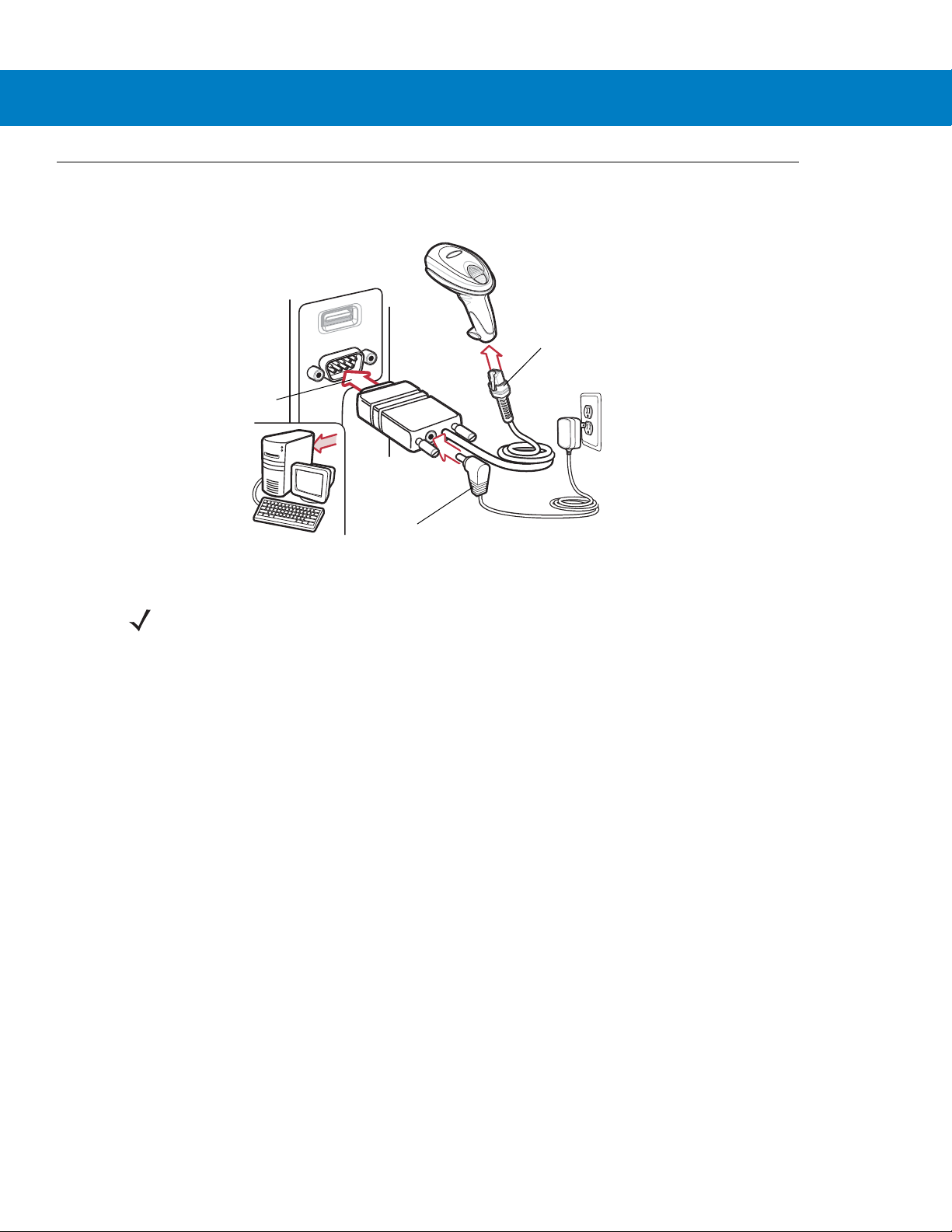
7 - 2 Symbol DS6708 Digital Scanner Product Reference Guide
Interface Cable
Serial Port Connector to
Host
Power Supply Cable
Connecting an RS-232 Interface
Connect the digital scanner directly to the host computer.
Figure 7-1
1. Attach the modular connector of the RS-232 interface cable to the cable interface port on the digital scanner
RS-232 Direct Connection
NOTE Interface cables vary depending on configuration. The connectors illustrated in Figure 7-1 are examples
only. The connectors may be different than those illustrated, but the steps to connect the scanner are the
same.
(see Installing the Interface Cable on page 1-3).
2. Connect the other end of the RS-232 interface cable to the serial port on the host.
3. Connect the power supply to the serial connector end of the RS-232 interface cable. Plug the power supply
into an appropriate outlet.
4. Select the RS-232 host type by scanning the appropriate bar code from RS-232 Host Types on page 7-6.
5. To modify any other parameter options, scan the appropriate bar codes in this chapter.
Page 97
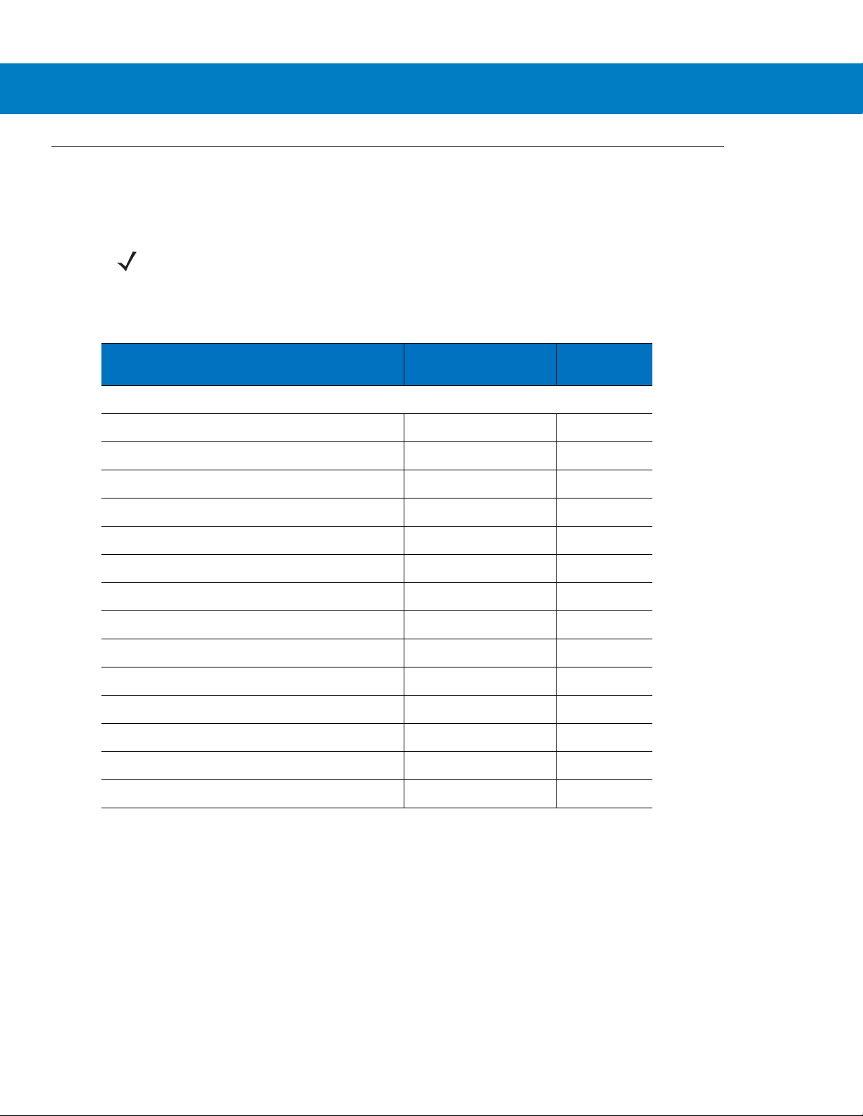
RS-232 Parameter Defaults
Table 7-1 lists the defaults for RS-232 host parameters. To change any option, scan the appropriate bar code(s)
provided in the RS-232 Host Parameters section beginning on page 7-4.
NOTE See Appendix A, Standard Default Parameters for all user preferences, hosts, symbologies, and
miscellaneous default parameters.
RS-232 Interface 7 - 3
Table 7-1
RS-232 Host Parameters
RS-232 Host Types Standard 7-6
Baud Rate 9600 7-7
Parity Type None 7-9
Stop Bit Select 1 Stop Bit 7-10
Data Bits 8-Bit 7-10
Check Receive Errors Enable 7-11
Hardware Handshaking None 7-11
Software Handshaking None 7-13
Host Serial Response Time-out 2 Sec 7-15
RTS Line State Low RTS 7-16
Beep on <BEL> Disable 7-16
Intercharacter Delay 0 msec 7-17
RS-232 Host Default Table
Parameter Default
Page
Number
Nixdorf Beep/LED Options Normal Operation 7-18
Ignore Unknown Characters Send Bar Code 7-18
Page 98

7 - 4 Symbol DS6708 Digital Scanner Product Reference Guide
RS-232 Host Parameters
Various RS-232 hosts use their own parameter default settings. Selecting standard, ICL, Fujitsu, Wincor-Nixdorf
Mode A, Wincor-Nixdorf Mode B, OPOS/JPOS, Olivetti, or Omron sets the defaults listed in Table 7-2.
Table 7-2
Transmit Code ID
Data Transmission
Format
Suffix
Baud Rate
Parity
Hardware
Handshaking
Software
Handshaking
Serial Response
Time-out
Stop Bit Select
ASCII Format
Terminal Specific RS-232
Parameter ICL Fujitsu
Yes Yes Yes Yes Yes Yes
Data/Suffix Data/Suffix Data/Suffix Data/Suffix Prefix/Data/
CR (1013) CR (1013) CR (1013) CR (1013) ETX (1002) CR (1013)
9600 9600 9600 9600 9600 9600
Even None Odd Odd Even None
RTS/CTS
Option 3
None None None None Ack/Nak None
9.9 Sec. 2 Sec. 9.9 Sec. 9.9 Sec. 9.9 Sec. 9.9 Sec.
One One One One One One
8-Bit 8-Bit 8-Bit 8-Bit 7-Bit 8-Bit
Wincor-
Nixdorf
Mode A
None RTS/CTS
Option 3
Wincor-
Nixdorf Mode
B/OPOS/JPOS
RTS/CTS
Option 3
Olivetti Omron
Data/Suffix
Suffix
None None
Beep On <BEL>
RTS Line State
Prefix
*In the Nixdorf Mode B, if CTS is low, scanning is disabled. When CTS is high, scanning is enabled.
** If you scan Nixdorf Mode B without connecting the digital scanner to the proper host, it may appear
unable to scan. If this happens, scan a different RS-232 host type within 5 seconds of cycling power to the
digital scanner.
Disable Disable Disable Disable Disable Disable
High Low Low Low = No data
to send
None None None None STX (1003) None
Low High
Page 99

RS-232 Host Parameters (continued)
Selecting ICL, Fujitsu, Wincor-Nixdorf Mode A, Wincor-Nixdorf Mode B, OPOS/JPOS, Olivetti, or Omron enables
the transmission of code ID characters listed in Table 7-3. These code ID characters are not programmable and
are separate from the Transmit Code ID feature. Do not enable the Transmit Code ID feature for these terminals.
RS-232 Interface 7 - 5
Table 7-3
UPC-A
UPC-E
EAN-8/JAN-8
EAN-13/JAN-13
Code 39
Codabar
Code 128
I 2 of 5
Code 93
D 2 of 5
GS1-128 (formerly
UCC/EAN-128)
Terminal Specific Code ID Characters
Code Type ICL Fujitsu
AAA A AA
EEC C CE
FF FF B B B FF
FFA A AF
C <len> None M M M <len> C <len>
N <len> None N N N <len> N <len>
L <len> None K K K <len> L <len>
I <len> None I I I <len> I <len>
None None L L L <len> None
H <len> None H H H <len> H <len>
L <len> None P P P <len> L <len>
Wincor-
Nixdorf
Mode A
Wincor-Nixdorf
Mode B/
OPOS/JPOS
Olivetti Omron
MSI
Bookland EAN
Trioptic
Code 11
IATA
Code 32
None None O O O <len> None
FFA A AF
None None None None None None
None None None None None None
H<len> None H H None None
None None None None None None
Page 100

7 - 6 Symbol DS6708 Digital Scanner Product Reference Guide
RS-232 Host Types
To select an RS-232 host interface, scan one of the following bar codes.
Standard RS-232
Wincor-Nixdorf RS-232 Mode A
1
ICL RS-232
Wincor-Nixdorf RS-232 Mode B
Olivetti ORS4500
Omron
1
Scanning Standard RS-232 activates the RS-232 driver, but does not change port settings (e.g., parity, data bits,
handshaking). Selecting another RS-232 host type bar code changes these settings.
 Loading...