

Page 1
RS 2200/3200 Series
Series 3100
Quick Reference
Page 2

© 2002 SYMBOL TECHNOLOGIES, INC. All rights reserve d.
Symbol reserves the right to make changes to any product to improve reliability, function,
or design.
Symbol does not assume any product liability arising out of, or in connection with, the
application or use of any product, circuit, or application described herein.
No license is granted, either expressly or by implication, estoppel, or otherwise under any
patent right or patent, covering or relating to any combination, system, apparatus,
machine, material, method, or process in which Symbol products might be used. An
implied license exists only for equipment, circuits, and subsystems contained in Symbol
products.
Symbol and the Symbol logo are registered trademarks of Symbol Technologies, Inc. Other
product names mentioned in this manual may be trademarks or registered trademarks of
their respective companies and are hereby acknowledged.
Symbol Technologies, Inc.
One Symbol Plaza
Holtsville, N.Y. 11742-1300
http://www.symbol.com
Patents
This product is covered by one or more of the following U.S. and foreign Patents:
U.S. Patent No. 4,496,831; 4,593,186; 4,603,262; 4,607,156; 4,652,750; 4,673,805; 4,736,095; 4,758,717;
4,760,248; 4,806,742; 4,816,660; 4,845,350; 4,896,026; 4,897,532; 4,923,281; 4,933,538; 4,992,717; 5, 015,833;
5,017,765; 5,021,641; 5,029,183; 5,047,617; 5,103,461; 5,113,445; 5,130,520; 5,140,144; 5,142,550; 5,149,950;
5,157,687; 5,168,148; 5,168,149; 5,180,904; 5,216,232; 5,229,591; 5,230,088; 5,235,167; 5,243,655; 5, 247,162;
5,250,791; 5,250,792; 5,260,553; 5,262,627; 5,262,628; 5,266,787; 5,278,398; 5,280,162; 5,280,163; 5, 280,164;
5,280,498; 5,304,786; 5,304,788; 5,306,900; 5,321,246; 5,324,924; 5,337,361; 5,367,151; 5,373,148; 5, 378,882;
5,396,053; 5,396,055; 5,399,846; 5,408,081; 5,410,139; 5,410,140; 5,412,198; 5,418,812; 5,420,411; 5,436,440;
5,444,231; 5,449,891; 5,449,893; 5,468,949; 5,471,042; 5,478,998; 5,479,000; 5,479,002; 5,479,441; 5, 504,322;
5,519,577; 5,528,621; 5,532,469; 5,543,610; 5,545,889; 5,552,592; 5,557,093; 5,578,810; 5,581,070; 5, 589,679;
5,589,680; 5,608,202; 5,612,531; 5,619,028; 5,627,359; 5,637,852; 5,664,229; 5,668,803; 5,675,139; 5, 693,929;
5,698,835; 5,705,800; 5,714,746; 5,723,851; 5,734,152; 5,734,153; 5,742,043; 5,745,794; 5,754,587; 5, 762,516;
5,763,863; 5,767,500; 5,789,728; 5,789,731; 5,808,287; 5,811,785; 5,811,787; 5,815,811; 5,821,519; 5,821,520;
5,823,812; 5,828,050; 5,848,064; 5,850,078; 5,861,615; 5,874,720; 5,875,415; 5,900,617; 5,902,989; 5, 907,146;
5,912,450; 5,914,478; 5,917,173; 5,920,059; 5,923,025; 5,929,420; 5,945,658; 5,945,659; 5,946,194; 5, 959,285;
6,002,918; 6,021,947; 6,031,830; 6,036,098; 6,047,892; 6,050,491; 6,053,413; 6,056,200; 6,065,678; 6, 067,297;
6,068,190; 6,082,621; 6,084,528; 6,088,482; 6,092,725; 6,101,483; 6,102,293; 6,104,620; 6,114,712; 6,115,678;
6,119,944; 6,123,265; 6,131 ,814; 6,138,180; 6,142,379; 6,172,478; 6,176,428; 6,178,426; 6,186,400; 6,188,681;
6,209,788; 6,216,951; 6,220,514; 6,243,447; 6,244,513; 6,247,647; 6,308,061; 6,250,551; 6,295,031; D305, 885;
D341,584; D344,501; D359,483; D362,453; D363,700; D363,918; D370,478; D383,124; D391,250; D405,077;
D406,581; D414,171; D414,172; D418,500; D419,548; D423,468; D424,035; D430,158; D430,159; D431,562;
D436,104.
Invention No. 55,358; 62,539; 69,060; 69,187 (Taiwan); No. 1,601,796; 1,907,875; 1,955,269 (Japa n); European
Patent 367,299; 414,281; 367,300; 367,298; UK 2,072,832; France 81/03938; Italy 1,138,713.
rev. 11/01
Quick Reference
Page 3

Introduction
The Series 3100 terminals are ligh tw eig ht , batt e ry powered,
hand-held computer systems. Data can be entered using the
terminal keyboard, the integr ated las er scanner, or the tethered
bar code scanners.
The Series 3100 includes both batch and radio terminals. The
PDT 3100 performs direct communications. The PDT 3110
and 3124 perform Spectrum One radio communications. The
PDT 3140 performs Spectrum 24 radio communications. All
Series 3100 terminals can be used as remote terminals for
collecting and storing data that is late r uploaded to a h ost
computer.
About this Guide
This guide presents information on the parts of a Series 3100
terminal and instructions for the following procedures:
• Powering the terminal on and off
• Performing communications
• Charging the batt eries
• Replacing the batteries
• Connecting the modems
• Connecting the terminal to a printer
• Configuring the scanner trigger
• Attaching a tethered scanner
• Using the scanners
3
Page 4

4
PDT 3100
DECODE SCAN
Parts of the Series 3100 Terminal
1
2
3
9
4
5
6
6
6
7
8
10
9
11
14
PART NO.:
15
3100-9M0L050
SYMBOL TECH, INC.
S/N: B029721
CONTINUOUS OPERATION OF BACKUP
BATTERY SYSTEM.
BEFORE STORING UNIT FOR EXTENDED
WARNING
PERIODS (OVER 1 MONTH) CONSULT
OPERATING MANUAL OR CALL SYMBOL
FIELD SERVICE.
REPLACE BATTERIES QUICKLY TO INSURE
ALKALINE
BATTERY
12
16
13
Quick Reference
Page 5

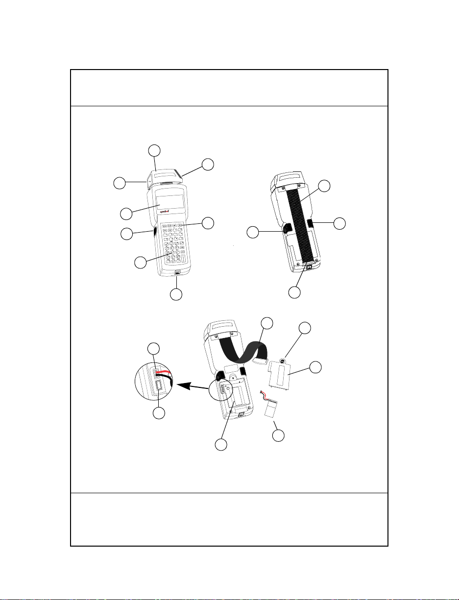
Parts of the Series 3100 terminal include:
1. Integrated Rotatable Laser Scanner
2. Scanner Window
3. Scanner LED
4. LCD Display Screen
PWR Key
5.
6. Alpha/Scanner Triggers
7. Keyboard
8. Serial Port (RJ -4 1)
9. Hand Strap
10. Hand Strap Hook
11. Battery Compartment Latch
12. Battery Compartment Cove r
13. Battery Compartment
14. Alkaline Battery Soc ket
15. Rechargeable NiCd Battery Socket
16. Battery
5
Page 6

6
Power On and Off
Note: If the terminal is powered by a NiCd battery, charge the
battery fully before using the terminal.
To turn the terminal on or off, press
PWR.
Battery Charging and Communications
T o charge the PDT 3100’s batteries or perform communications,
you have the option of using either a 31XX cradle or the 3115
Communications/Charger Adapter.
3115 Communications/Charger Adapter
The Series 3100 has an optional communi cations/charger
adapter (CCA) that facilitates communication with a host when
no cradle is available, an d provides power to the termina l from
a wall-mounted power supply for battery charging during
terminal use and flash EPROM programming.
Battery Charging
To provide power directly to a terminal for charging the
NiCd battery:
1. Plug the 10-pin RJ41 connector into the base of the Series
3100 terminal.
2. Plug the connector from the 15V power supply,
P/N 55915-00 -00 (US, 1 15V) o r 60507-00- 00 (Internatio nal,
230V) into the power input jack (J1) on the CCA.
Quick Reference
Page 7
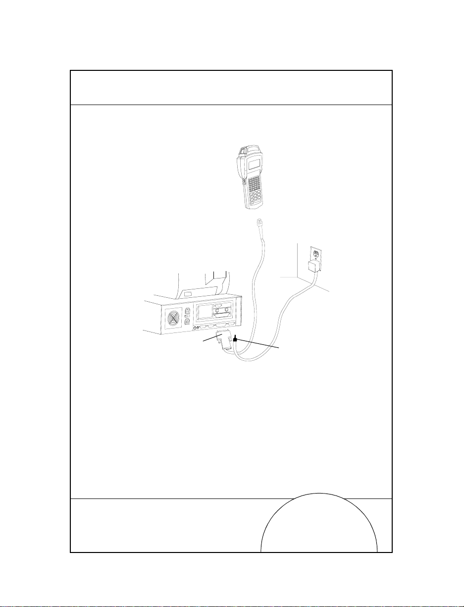
3. Plug the power supply into a wall socket.
115V
Keyboard
Mouse
COM A
COM B
Parallel
VGA
Wall
Phone
PWR
CTL
SHF
E
NC
F
D
LR
C
C
J
B
I
A
H
O
G
N
F
LAMP
M
T
L
S
K
LIGHT
R
DARK
Y
Q
X
P
W
V
U
SPACE
F9
BSP
Z
F8
9
F7
F6
8
F5
7
6
F4
F3
5
F2
4
3
F1
2
=
1
F10
ENTER
0
RJ-41 Connector
3115 CCA
7
DB-25 Connector
Power Input Jack
NiCd batteries require 12 to 16 hours to recharge fu lly.
The terminals may be used while the battery is being
charged.
Note: Alkaline batteries cannot be charged in the terminal.
To charge the batteries more quickly, use the cradle as
detailed in 31XX Cradles, Battery Charging.
Page 8

8
Communications
Note: It is NOT necessary to connect the terminal to a power
source for communications.
To communicate with a PC or printer:
1. Plug the 10-pin RJ41 connector into the base of a Series
3100 terminal.
2. Plug the DB25 connector into the host’s communications
port.
To connect the CCA to a mode m:
1. Plug the 10-pin RJ41 connector into the base of a Series
3100 terminal.
2. Insert a female-to-male gender changer on the female
DB25 connector before plu ggi ng the connector into the
modem.
Note: The CCA is shipped set for RS-232 communications with
a PC. To use the CCA with a modem or printer may
require changing the internal communications settings.
Refer to the installation instructions (P/N 70-1 1314-01).
Quick Reference
Page 9
31XX Cradles
PDT 3100
CHARGING
COMM
The single-slot and four-slot cradles are optional devices used
for charging the ba tteries and perf orming host comm unication
with the terminal.
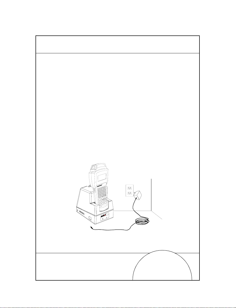
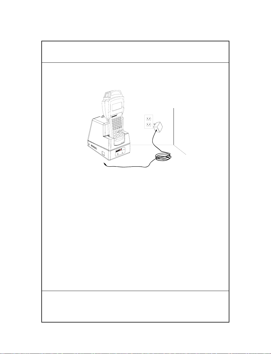
Battery Charging
To recharge the NiCd battery pack in the cradle:
1. Plug the power supply cord round plug in the power
connector on the side of the cradle.
2. Connect the power supply cord AC plug to a standard
electrical outlet .
3. Place the terminal in the cradle.
The battery pack is fully charged in appr oxima te ly 90
minutes.
PWR
CTL
SHF
E
FNC
D
CLR
C
J
B
I
A
H
O
G
N
F
LAMP
M
T
L
S
K
LIGHT
R
DARK
Y
Q
X
P
W
V
U
SPACE
F9
BSP
Z
F8
9
F7
F6
8
F5
7
6
F4
F3
5
F2
4
3
F1
2
=
1
F10
ENTER
0
9
Page 10
10
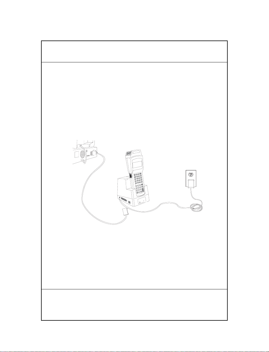
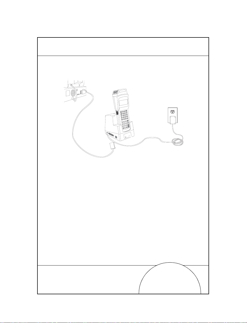
Communications
To communicate using the cradle:
1. Perform Steps 1 - 2 from the section Battery Charging.
2. Connect th e cradle to the host computer using a null
modem cable
3. Insert the terminal in the cradle and perform the
communication steps as detailed in the Series 3100 System
Administration Manual (P/N 62605-00-90) or Series 3000
Application Programmer’s Guide (P/N 59045-00-92).
4. If the cradle is equipped with a modem (single-slot
cradles only), connect it directly to t he telephone wall ja ck
and proceed as directed in the Series 3100 System
Administration Manual.
For more information on the single- and four-slot cradles,
refer to the 3165/31 66 Cradle Base Modules Quick Reference
Guide (P/N 70-11313-xx).
Quick Reference
Page 11
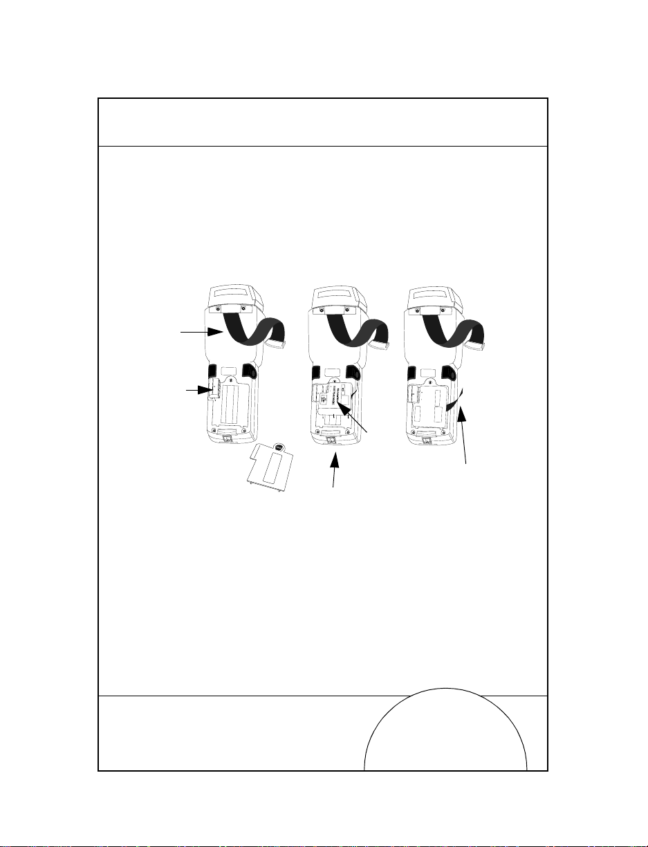
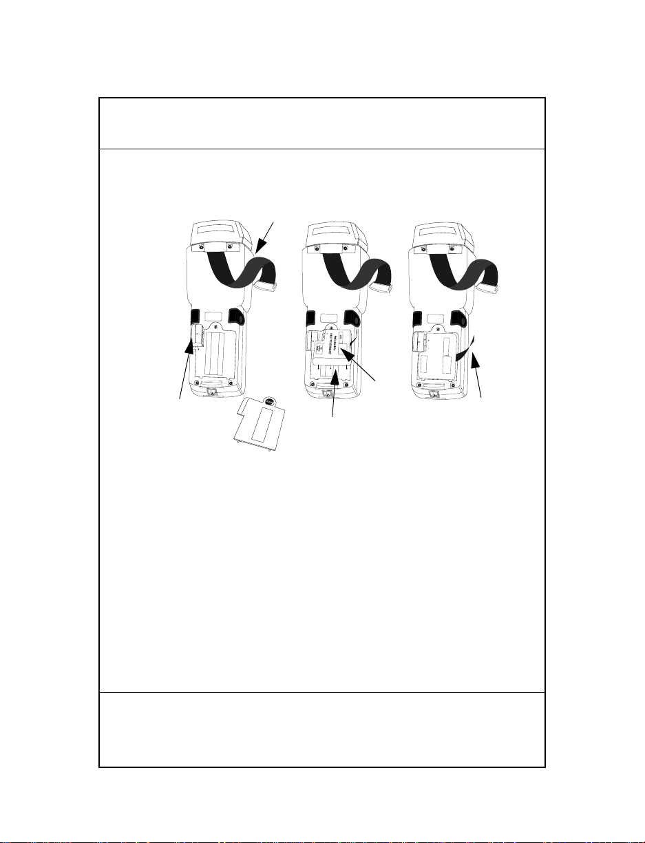
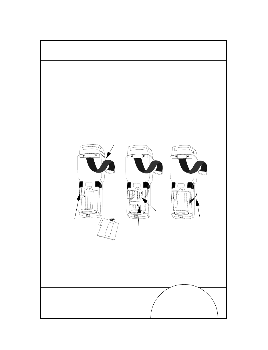
Replacing the Batteries
To replace the NiCd or NiMH battery:
1. Turn the termin al off.
2. Release the hand strap, unlock the batte ry compartment
door and remove it.
Hand
Strap
11
Battery
Adapter
Compartment
Battery
Door
PART NO.:
3100-9M0L050
SYMBOL TECH, INC.
S/N: B029721
PART NO.:
3100-9M0L050
S/N: B029721
SYMBOL TECH, INC.
Battery
NiCd
Battery
PART NO.:
3100-9M0L050
S/N: B029721
SYMBOL TECH, INC.
SEALED TYPE-RECHARGEABLE
Nickel Cadmium Battery
ELECTRONICS
HOUSTON
K•TEC
GATES
Strap
Compartment
3. Position the battery adapter in holding plug and press
into place.
4. Fit the NiCd or NiMH batte ry pack in compartment next
to adapter. Verify that removal strap is accessible (not
tucked under battery), before pressing battery in place.
Note: NiMH batteries cannot be charged in the terminal
through the Communications/Charger Adapter.
Page 12

12
5. Verif y th at bat tery and adapter are p r op erly seated.
6. Replace and lock battery compartment door.
7. Replace handstrap.
Quick Reference
Page 13

Connecting the Modems
Direct Connect
Some terminals use an optional interna l modem th a t comm unicat es at
rates of up to 14,400 bps (with v.32 bis data compression). There are
specific firmware settings which are used to configure the
modem’s hardware and software for proper operation and
regulatory complianc e. The ter m ina l’s appli cati o n can con trol
these settings and ena ble you to view a nd amend the setting s for
country/region, pulse/tone dialing, or repeat dial timing.
Incorrectly defining these settings can lead to illegal use of the
modem and can create unreliable operation. The application
developer should consult the Series 3000 Application
Programmer’s Reference Manual for correct settings.
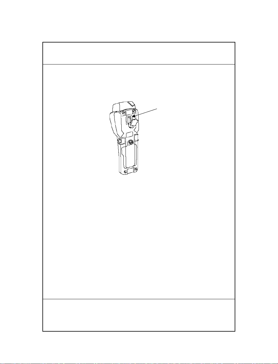
If your terminal is equipped with a direct connect modem,
connect the modem as follows:
1. Turn the termin al off.
2. Release the hand strap on the back of the terminal.
13
Page 14
14
3. Detach the protective plug covering the modem jack on
the back of the terminal and plug in one of the telephone
cord’s connectors.
RJ-41 Jack
4. Plug the cord’s other connector into a telephone jack.
5. Turn the terminal back on.
Quick Reference
Page 15
Acoustic
Some Series 3100 termin als are e quipped wit h a built-i n acoustic
modem which allows dir ect data t ransm ission over a te lephone
line.
If your terminal is equipped with an acoustic modem, connect
the modem as follows:
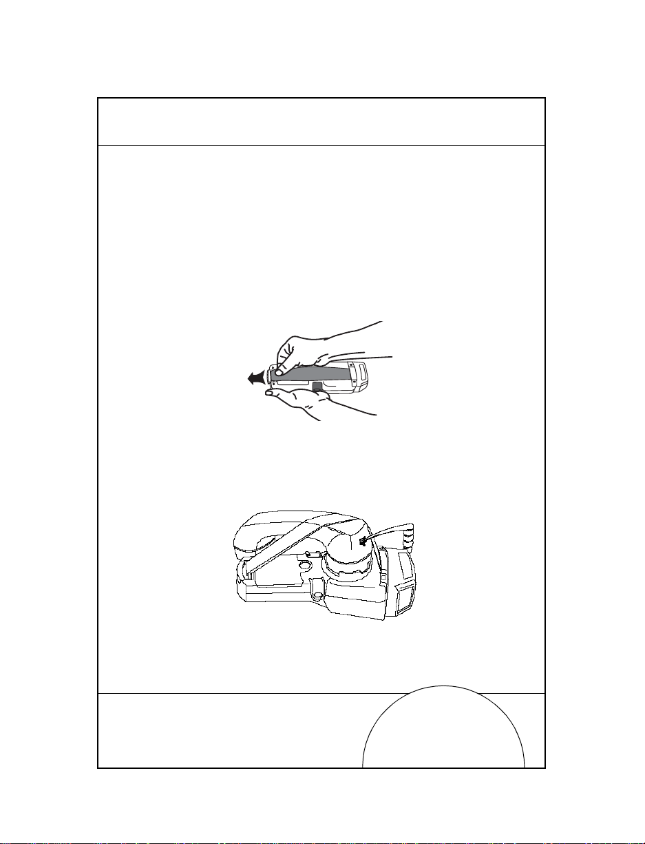
1. Turn the termin al off.
2. Release the hand strap on the back of the terminal.
3. Slide the mouthpiece of the telephone in to position on the
muff. Place the hand strap over the telephone handset as
shown below and reattach the strap.
4. Turn the terminal back on.
15
Page 16
16
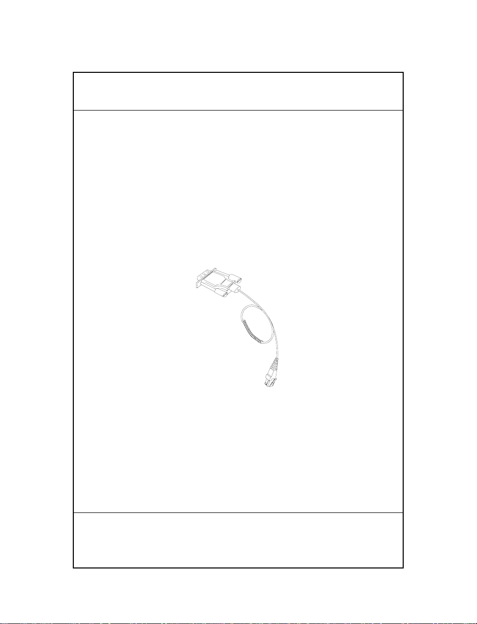
Connecting the Terminal to a Printer
The Series 3100 has an optional cable (p/n 25-10413-01) which is
used to connect the terminal to a PS-1000 Series printer or a
tethered PS-200 printe r (P/N 20-11062-03).
To connect the terminal to one of the printers listed abov e:
1. Plug the 10-pin RJ41 connector into the base of a Series
3100 terminal.
2. Plug the DB9 connector in the communications port on
the printer.
DB9
RJ-41
Quick Reference
Page 17
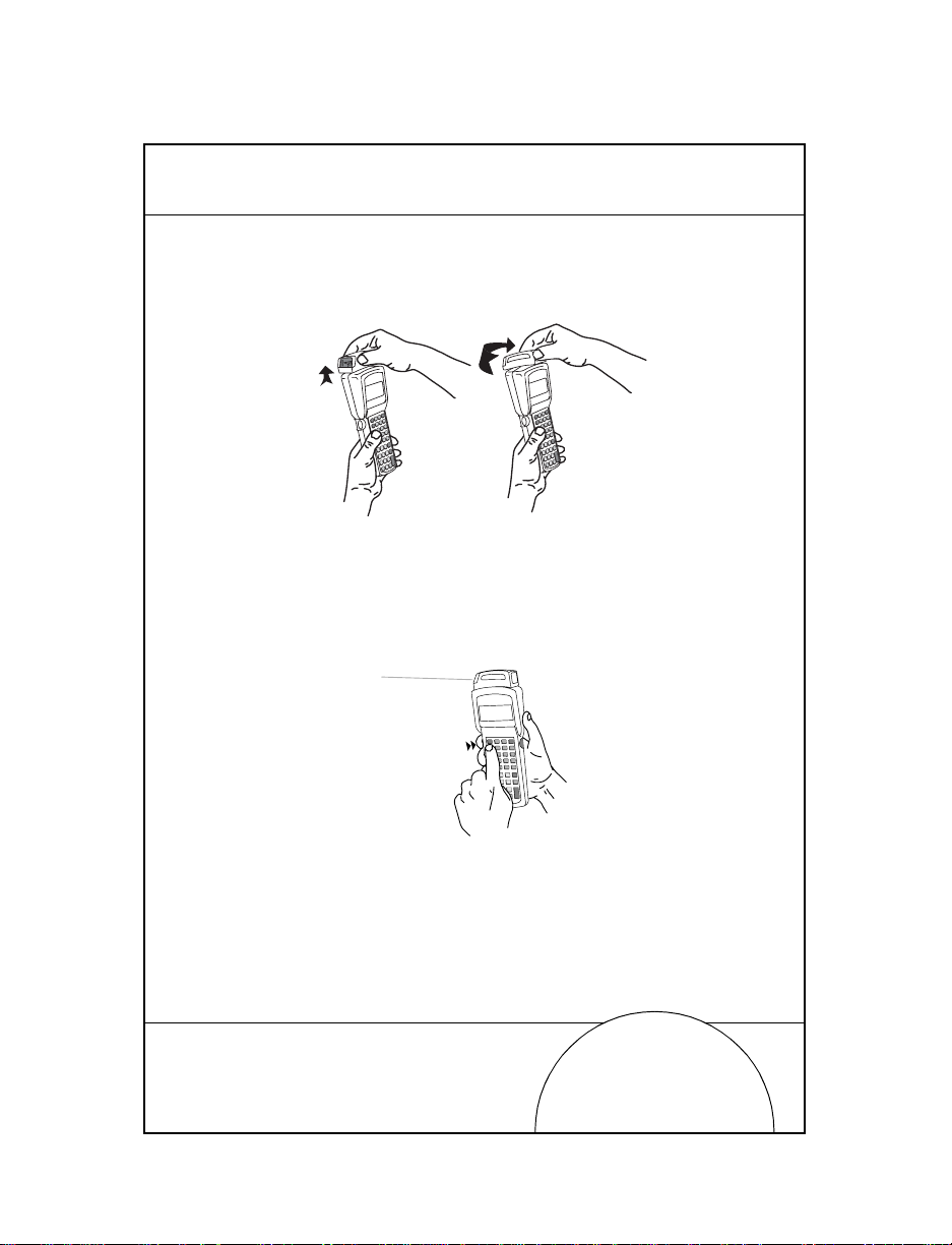
Using the Integrated Laser Scanner
The integrated scanner has a unique trigger that the operator
can configure. To select the trigger and use the integrated laser
scanner:
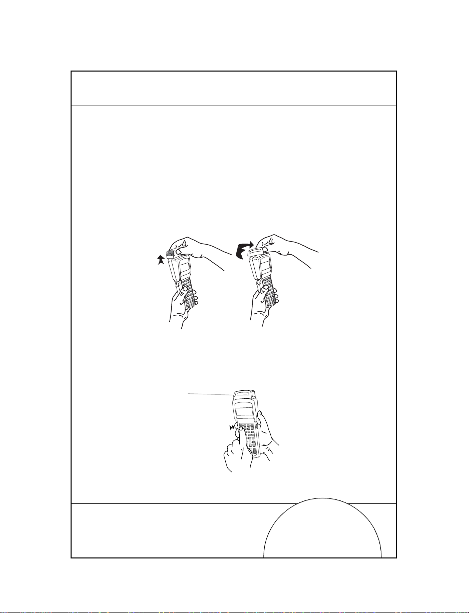
1. Power on the syste m and sca nn er by pressing
scanner trigger.
2. Lift and turn the scanner to the direction you wish to scan.
The scanner turns toward the back of the terminal.
PWR or the
17
3. Press the
comfortable using (see the figure below). This selects the
scanner trigger. The other trigger defaults to an ALPHA
shift key on the 3 5-key terminal.
FUNC key and the trigger you are most
Page 18
18
4. Point the scanner at the bar code and press the trigger or
press the soft tri gger key (
covers the entire length of the bar code.
The terminal indicates a successful scan by illuminating
the green scanner LED, beeping one or more times, and/
or displaying the decoded bar code on the screen.
ENTER). The thin, red laser beam
Quick Reference
Page 19
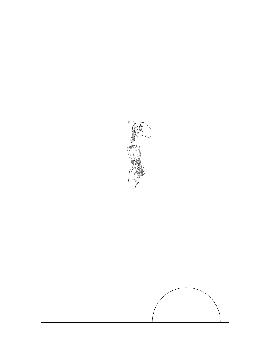
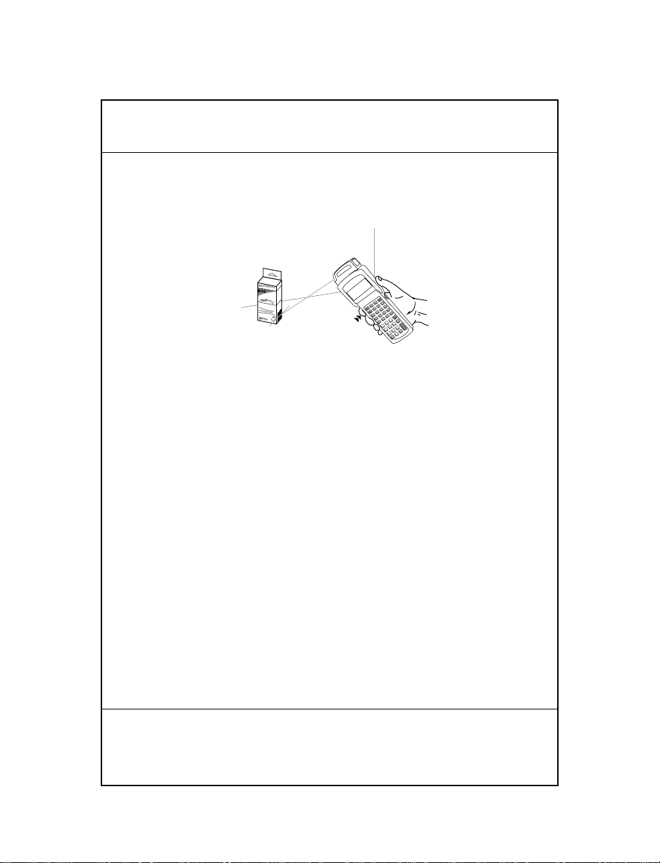
Connecting and Using a Tethered Scanner
To attach a wand or laser scanner to the Series 3100 terminal:
1. Turn the system off.
2. Remove the plastic cap in the top of the ter m i nal.
3. Plug the scanner into the top of the terminal as shown
below.
4. Aim the scanner at the bar code and press the trigger.
Note: Depending on your application, you may need to turn on
the terminal before using the scanners.
19
5. If using a wand scanner , lightly touch the scanner tip to
the white space at th e left side of t he bar code a nd move it
to the right.
Page 20

20
IEC825/EN60825 Class 1 Scanner
Series 3100 termi nals are equipped with an IEC825/EN60825
scanner operate on an emissions accumulator or “gas tank”
which determines the amount of scan time that you have
available. To meet low power consumption standards, the
scanner cannot sc an cont inu ou sly.
If the gas tank runs out of scan time, the terminal emits a long
low beep. Release the scan trigger and wait until the terminal
emits a long high beep, indicating that it ac crued enough scan
time for you to resume scanning.
Guide utilisateur
Page 21

Introduction
Les terminaux de la série 3100 sont des ordinateurs portables,
légers, alimentés par batterie. Ils permettent de saisir des
données à l'aide du clav ier du t er mina l, du lecteur laser intégré
ou d'un lecteur de codes à barres raccordé par câble.
La série 3100 comprend des term in aux batch et radio. Le
terminal PDT 3100 gère les communicat ion s directes, les
modèles PDT 3110 et 3124 les communications radio Spectrum
One, et le PDT 3140 les communications radio Spectrum 24.
T ous les termina ux 3100 peuvent êtr e utilisé s comm e terminau x
distants pour la collecte et le stockage des données qui seront
ensuite téléchargées sur un ordinateur central.
Objet de ce guide
Ce guide décrit les différents composants du terminal 3100 et
fournit des instructions relatives aux opérations suivantes
•Position marche/arrêt
• Communications
• Charge des batteries
• Remplacement des batteries
• Raccordement des modems
• Raccordement d'un e impr im an te au term in al
• Configuration de la gâchette du lecteur
• Branchement d'un lecteur r a ccordé par câble
• Utilisation des lecteurs
21
Page 22
22
PDT 3100
DECODE SCAN
Composants du terminal 3100
1
2
3
9
4
5
6
6
6
7
8
10
9
11
14
PART NO.:
15
3100-9M0L050
SYMBOL TECH, INC.
S/N: B029721
CONTINUOUS OPERATION OF BACKUP
BATTERY SYSTEM.
BEFORE STORING UNIT FOR EXTENDED
WARNING
PERIODS (OVER 1 MONTH) CONSULT
OPERATING MANUAL OR CALL SYMBOL
FIELD SERVICE.
REPLACE BATTERIES QUICKLY TO INSURE
ALKALINE
BATTERY
12
16
13
Guide utilisateur
Page 23

Composants du terminal 3100 :
1. Tête de lecture laser pivotante intégrée
2. Fenêtre du lecteur
3. Témoin du lecteu r
4. Ecran LCD
5. Touche
PWR
6. Gâchettes Alpha/lecteur
7. Clavier
8. Port série (RJ-41)
9. Sangle
10. Crochet de sangle
11. Verrou du logement de batterie
12. Trappe du logement de batterie
13. Logement de batterie
14. Prise pour pile alcaline
15. Prise pour batterie NiCd rechargeable
16. Batterie
23
Page 24

24
Marche/arrêt
Remarque: si le terminal est alimenté par une batterie NiCd,
chargez-la complètement avant d'utiliser le terminal.
Pour mettre le terminal en marche ou l'arrêter, appuyez sur la
PWR.
touche
Charge de la batterie et communications
Pour charger les batteries du PDT 3100 ou établir une
communication, vous pouvez utiliser un puits de chargement
31XX ou l'adaptateur 3115 Communication/charge.
Adaptateur 3115 Communication/charge
Le 3100 peut être utilisé avec un adaptateur CCA (Communication/charge) optionnel qui assure les communications avec
l'ordinateur central lorsqu'aucun puits de chargement n'est
disponible, et alimente le terminal à partir d'une alimentation
pendant la période d'utilisation du termin al et la
programmation flash EPROM.
Mise en charge des batteries
Pour alimenter directe m ent le terminal et charger les batteries NiCd :
1. Branchez le connecteur RJ41 à 10 broch es da ns la ba se du
terminal 3100.
2. Branchez le connecteur d'alimentation 15V,
P/N 55915-00-00 (USA, 115V) ou 60507-00-00
(International, 230V) dans la prise d'alimentation
(J1) du CCA.
Guide utilisateur
Page 25

3. Branchez le cordon d’alimentation sur secteur.
115V
Keyboard
Mouse
COM A
COM B
Parallel
VGA
Wall
Phone
PWR
CTL
SHF
E
NC
F
D
LR
C
C
J
B
I
A
H
O
G
N
F
LAMP
M
T
L
S
K
LIGHT
R
DARK
Y
Q
X
P
W
V
U
SPACE
F9
BSP
Z
F8
9
F7
F6
8
F5
7
6
F4
F3
5
F2
4
3
F1
2
=
1
F10
ENTER
0
RJ41 Connector
3115 CCA
25
DB 25 Connector
Power Input Jack
La charge complète des batteries NiCd nécessite 12 à 16
heures. Vous pouvez cependant utiliser les terminaux
pendant la charge des batteries.
Remarque: Les piles alcalines ne peuvent pas être chargées dans le
terminal.
Pour accélérer la charge des batteries, utilisez le puits de
chargement selon les indications spécifiées dans les
Page 26

26
paragraphes Puits de chargement 31XX, Mise en charge des
batteries.
Communications
Remarque: Il n'est pas nécessaire de raccorder le terminal à une
alimentation pour établir une communication.
Procédure de communication avec un PC ou une
imprimante :
1. Branchez le connecteur RJ41 à 10 broch es da ns la ba se du
terminal 3100.
2. Branchez le connecteur DB25 dans le port de
communication de l'ordi nat eur ce nt ra l.
Procédure de raccor dem en t du CCA à un modem :
1. Branchez le connecteur RJ41 à 10 broch es da ns la ba se du
terminal 3100.
2. Insérez un adaptateur femelle/mâle dans le connecteur
DB25 femelle avant de brancher le connect eur su r le
modem.
Remarque: Le CCA est configuré pour des communications
RS-232 avec un PC. Pour utiliser le CCA avec un
modem ou une imprimante, il peut s'avérer nécessaire
de modifier les paramètres de communication internes.
Reportez-vous aux instructions d'installation (P/N
70-11314-01).
Guide utilisateur
Page 27

Puits de chargement 31XX
Les puits de chargement à une ou quatre positions sont des
accessoires disponibles en option permettant la charge des
batteries et les communications entre l'ordinateur central et le
terminal.
Mise en charge des batteries
Pour recharger le pack de b a tterie Ni Cd dans le puits de
chargement :
1. Brancher la f iche d'a limentatio n ro nde dan s le con necteur
situé sur le côté du puits.
2. Brancher le cordon d'alimentation (CA) sur secteur.
3. Placer le terminal dans le puits de chargement.
La charge complète des batteries nécessite environ 90
minute.
27
Page 28
28
PDT 3100
CHARGING
COMM
PWR
CTL
SHF
E
FNC
D
CLR
C
J
B
I
A
H
O
G
N
F
LAMP
M
T
L
S
K
LIGHT
R
DARK
Y
Q
X
P
W
V
U
SPACE
F9
BSP
Z
F8
9
F7
F6
8
F5
7
6
F4
F3
5
F2
4
3
F1
2
=
1
F10
ENTER
0
Communications
Pour communiquer avec le puits de chargement :
1. Suivez les étapes 1 et 2 du paragraphe Mise en charge des
batteries.
2. Raccordez le puits de chargement à l'ordinateur récepteur
au moyen d'un câble null modem.
3. Insérez le termina l dans le puits et suivez la proc édure de
communication décrite dans le Manuel de gestion du
Guide utilisateur
Page 29
système 3100 (P/N 62605-00-90) ou dans le Guide du
programmeur des applications série 3000 (P /N 59045-00-92).
4. Si le puits de chargement est équipé d'un modem (puits
de chargement à une position seulement), connectez-le
directement à la prise téléphonique et suivez les
procédures indiquées dans le Manuel de gestion du
système 3100.
Pour plus d'informations sur les puits de chargement à une ou quatre
positions, consultez le Guide utilisateur des puits de chargement
(P/N 70-11313-xx).
29
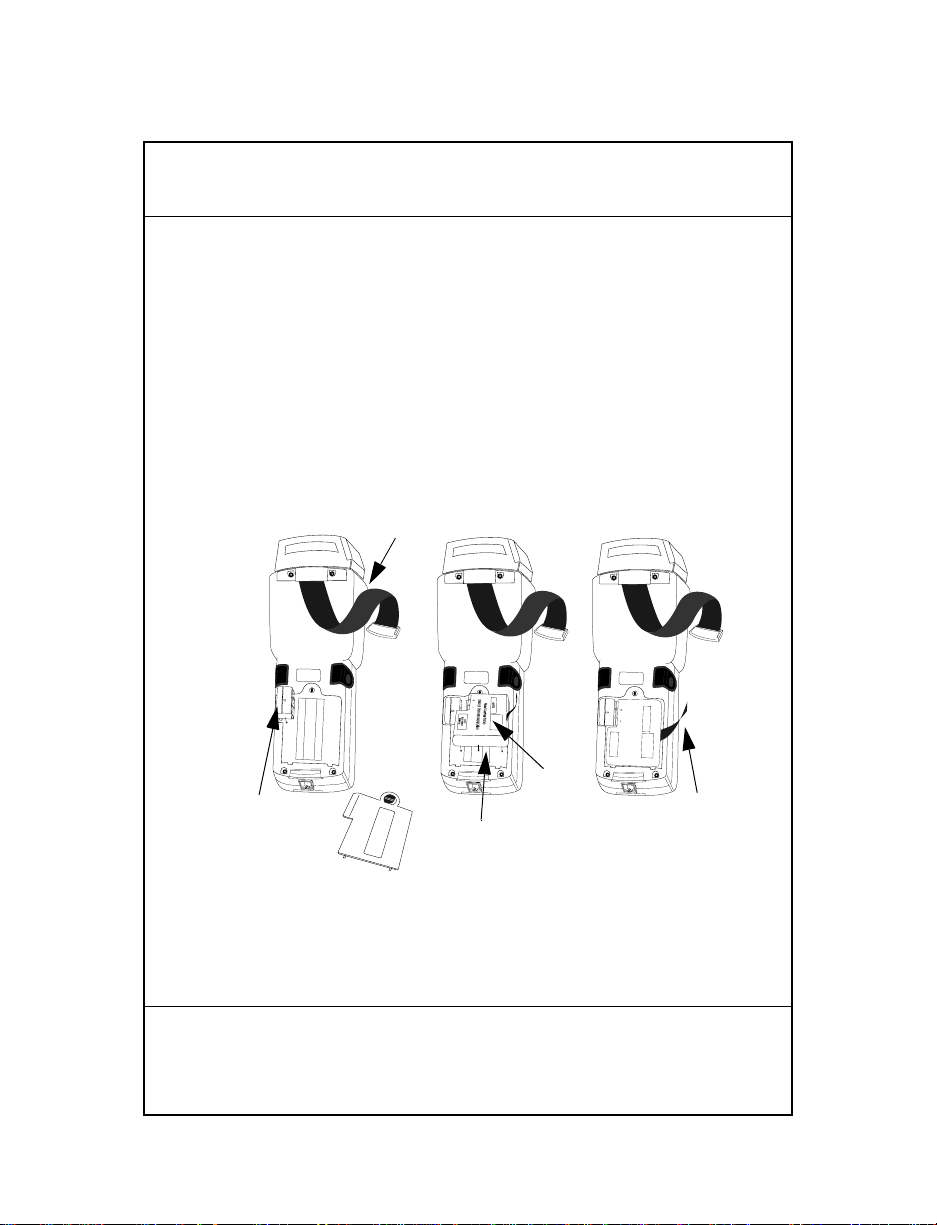
Remplacement des piles
Pour remplacer la batterie NiCd ou NiMH procédez de la
manière suivante :
1. Mettez le terminal hors tension.
Page 30
30
2. Retirez la sangle, déverrouillez la trappe du logement de
pile et retirez-la.
Bandoulière
Adaptateur
de batterie
PART NO.:
3100-9M0L050
SYMBOL TECH, INC.
S/N: B029721
PART NO.:
3100-9M0L050
S/N: B029721
SYMBOL TECH, INC.
Logement de batterie
Batterie
NiCd
PART NO.:
3100-9M0L050
S/N: B029721
SYMBOL TECH, INC.
SEALED TYPE-RECHARGEABLE
Nickel Cadmium Battery
ELECTRONICS
HOUSTON
K•TEC
GATES
Ruban
Panneau du logement
de batterie
3. Positionnez l’adaptateur de batterie face à l’emplacement
correspondant, puis insérez-le.
4. Placez la batterie Nicd ou NiMH dans le logement face à
l’adaptateur. Vérifiez que le ruban d’extraction est
accessible et qu’il n’est pas coincé sous la batterie avant
d’insérer cette dernière dans le logement.
Remarque: il est impossible de charger les batteries dans le termi-
nal au moyen de l’adaptateur pour puits de communication/chargement.
5. Vérifiez que la batterie et l’adaptateur sont bien en place.
Guide utilisateur
Page 31

6. Remettez le panneau du logemen t de batt erie et
verrouillez-le.
7. Remettez la bandoulière en place.
Raccordement des modems
Connexion directe
Certains puits sont équipés d'un modem interne en option ; ce
modem qui communique à un débit de 14 400 bps maximum
(avec une compression de données v.42 bis) peut être raccordé
directement à une ligne téléphonique par l'intermédiaire du
port RJ-11 figurant dans l'illustration.
Remarque : Le puits à quatre positions ne comporte pas de
modem interne.
Il existe des réglag es spécifiques d e micropr ogramme des tinés à
configurer le matér iel et le log iciel du mo dem afin d'a ssurer s on
fonctionnement correct et sa conformité à la réglementation.
L'application du terminal peut contrôler ces réglages . Ceci vous
permet de visualiser et de modi fier les rég lages rel atifs au pays /
région, à la numérotation par im pulsion /t ona lit é ou à la durée
de répétition de numérotation. Ces réglages doivent être définis
correctement pour éviter une utilisation illégale du modem et
des problèmes de fonctionnement. Pour connaître les réglages
corrects, le concepteur de l'application devrait consulter le
manuel "Series 3000 Application Programmer's Reference
Manual" (manuel de référence à l'usage du programmateur
d'application de la série 3000).
Si votre terminal est équipé d'un tel modem, raccordez-le en
suivant la procédure suivante :
1. Mettez le terminal hors tension.
2. Retirez la sangle à l'arrière du terminal.
31
Page 32

32
3. Retirez le capuchon de protection recouvrant la prise
modem à l'arrière du terminal et branchez le cordon
téléphonique sur l'un des connecteurs.
RJ-41 Jack
4. Branchez l'autre extrémité du cordon sur la prise
téléphonique.
5. Mettez le terminal sous tensi on.
Modem acoustique
Certains terminaux de la série 3100 sont équipés d'un modem
acoustique intégré permettant la transmission directe des
données via une ligne téléphonique.
Si votre terminal est équipé d'un tel modem, raccordez-le en
suivant la procédure suivante :
1. Mettez le terminal hors tension.
Guide utilisateur
Page 33

2. Retirez la sangle à l'arrière du terminal.
3. Positionnez le micro du téléphone face au manchon.
Placez la sangle sur le combiné téléphonique comme
indiqué ci-dessous et fixez-la.
4. Mettez le terminal sous tension.
Raccordement du terminal à une imprimante
Les terminaux 3100 peuvent être équipés d'un câble optionnel
(p/n 25-10413-01) permettant le raccordement à une
imprimante série PS- 1 00 0 o u à un e imp r im an te PS -200
raccordée par câble (P/N 20-11062-03).
33
Pour raccorder le terminal à l'une des imprimantes ci-dessus
mentionnées :
1. Branchez le connecteur RJ41 à 10 broches sur la base du
terminal 3100 .
Page 34

34
2. Branchez le connecteur DB9 sur le port de communication
de l’impr im an te.
DB9
RJ-41
Guide utilisateur
Page 35

Utilisation du lecteur laser intégré
Le lecteur intégré dispose d'une gâchette simple que l'opér ateur
peut configurer. Pour sélectionner la gâchette et utiliser le laser
intégré :
1. Mettez le système et le lecteur sous tension en appuyant
sur la touche
2. Soulevez et pointez le lecteur vers l'article à décoder. Le
lecteur s'oriente vers l'arrière du terminal.
PWR ou sur la gâchette du lecteur.
35
3. Appuyez sur la touche
FUNC et sur la gâchette qui vous
convient le mieux (voir la fi gure ci-dessous). Cela permet
de sélectionner la gâchette du lecteur. L'autre gâchette
utilise par défaut la touche
ALPHA du terminal à 35
touches.
Page 36

36
4. Pointez le lecteur vers le code à barres et pressez la
gâchette ou pressez la touche (
rouge recouvre la totalité du code à barres.
Lorsque le décodage est réussi, le témoin vert s'allume su r
le lecteur, ce dernier émet un ou plusieurs bips et/ou
affiche le code à barres décodé sur l'écran.
ENTER). Le faisceau laser
Guide utilisateur
Page 37

Branchement et utilisation d’un lecteur
raccordé par câble
Pour raccorder un lecteur laser ou un crayon lecteur au terminal
3100 :
1. Mettez le système hors tension.
2. Retirez le capuchon en plastique sur la partie supérieure
du terminal .
3. Branchez le lecteur sur la partie supérieure du terminal
comme indiqué ci-dessous.
37
4. Pointez le lecteur vers le code à barres et pressez la
gâchette.
Remarque: selon votre application, il peut s'avérer nécessaire de
mettre le terminal en marche avant d'utiliser le
lecteur.
5. Si vous utilisez un crayon lecteur, placez délicatement
l'extrémité du lecteur sur l'espace vierge situé sur la
gauche du code à barres, puis déplacez-le vers la droite.
Page 38

38
Lecteur IEC825/EN60825 classe 1
Les terminaux 3100 équipés d'un lecteur IEC825/EN60825
utilisent un accumulateur ou "réservoir" qui d étermine le t emps
de lecture qui vous est imparti. Afin d'économiser les batteries,
le lecteur ne décode pas en continu.
Si le temps de le ctur e est dépassé, le t erminal émet un b ip gra ve
prolongé. Relâchez alors la gâchette du lecteur et attendez que
le terminal émette un bip aigu prolo ngé pour indiquer que vous
pouvez reprendre la lectur e.
Guide utilisateur
Page 39

Einführung
Bei den Terminals der Serie 3100 handelt es sich um leichte,
batteriebetr iebene Computersystem e für den Ha ndbetrieb. Die
Daten können über die Tastatur, den integrier ten Lasers cann er
oder die Handscanner eingegeben werde n.
Zur Serie 3100 zählen sowohl Stapel- als auch Funk-Terminals.
Das PDT 3100 überträgt Daten direkt. Die Geräte der Serie PDT
3110 und 3124 arbeiten mit der Spectrum One
Funkübertragung. Das PDT 3140 benutzt die Spectrum 24
Funkübertragung. Alle Terminals der Serie 3100 können als
abgesetzte Terminals für die Erfassung und Speicherung von
Daten eingesetzt werden, die anschließend in einen HostComputer eingespeist werden können.
Zu dieser Kurzübersicht
Diese Kurzübersicht bietet Informationen zu den Bestandteile n
der Terminal-Serie 3100 sowie Anleitungen zu den folgenden
Verfahren:
• Ein- und Ausschalten des Terminals
• Aufbau von Ver bindun gen
• Aufladen der Akkus
• Austauschen der Akkus
• Anschließen der Modems
• Anschließen des Terminals an einen Drucker
• Konfigurieren des Scanner-Auslösers
• Anschließen eines Handscanners
• Benutzen der Scanner
39
Page 40

40
PDT 3100
DECODE SCAN
Teile des Terminals der Serie 3100
1
2
3
9
4
5
6
6
6
7
8
10
9
11
14
PART NO.:
15
3100-9M0L050
SYMBOL TECH, INC.
S/N: B029721
CONTINUOUS OPERATION OF BACKUP
BATTERY SYSTEM.
BEFORE STORING UNIT FOR EXTENDED
WARNING
PERIODS (OVER 1 MONTH) CONSULT
OPERATING MANUAL OR CALL SYMBOL
FIELD SERVICE.
REPLACE BATTERIES QUICKLY TO INSURE
ALKALINE
BATTERY
12
16
13
Kurzübersicht
Page 41

Die Terminals der Serie 3100 bestehen aus folgenden Teilen:
1. Integrierter, drehbarer Laserscanner
2. Scannerfenster
3. Scanner-LED
4. LCD Display-Bildschirm
PWR-Taste
5.
6. Alpha-/Scanner-Auslöser
7. Tastatur
8. Serielle Schnitts tell e (RJ-41)
9. Handhalter
10. Aufhängung für Handha lt er
11. Akkufachlasche
12. Akkufachdeckel
13. Akkufach
14. 9V-Batteriestecker
15. Stecker für den wiederaufladbaren NiCd-Akku.
16. Akku
41
Page 42

42
Ein- und Ausschalten
Bitte beachten: Soll das Terminal über einen NiCd-Akku mit
Strom versorgt werden, muß der Akku vor
Inbetriebnahme des Terminals vollständig
geladen werden.
Zum Ein- ode r Ausschalten des Terminals drücken Sie
PWR.
Aufladen des Akkus und Kommunikationsau fbau
Zum Aufladen des Akkus des PDT 3100 oder für den
Kommunikationsaufbau haben Sie zwei Möglichkeiten:
Sie können dazu einen 31XX-Cradle oder den 3115
Kommunikations-/Lade-Adapter benutzen.
3115 Kommunikations-/Ladeadapter
Zur Serie 3100 wird zusätzlich ein Kommunikations-/
Ladeadapter (CCA) angeboten, der die Kommunikation mit
einem Host vereinfacht, wenn kein Cradle zur Verfügung steht.
Dieser Adapter versorgt das Terminal von einem an der Wand
montierten Netzgerät zum Aufladen der Akkus während der
Terminalbenutzung oder Flash EPROM Programmierung.
Laden des Akkus
Zur direkten Versorgung des Terminals mit Strom, um den
NiCd-Akkus zu laden, gehen Sie wie folgt vor:
1. Stecken Sie den 10-poligen RJ41-Stecker in die entsprechende Buchse des Terminals der Serie 3100.
2. Stecken Sie den Stecker einer 15 V Netzversorgung
(P/N 55915-00-00 (US, 115 V) oder 60507-00-00
(International, 230 V) in die Eingangsbuchse (J1) des
Kommunikations-/Ladeadapters (CCA).
Kurzübersicht
Page 43

3. Schließen Sie das Netzgerät an eine Wandsteckdose an.
115V
Keyboard
Mouse
COM A
COM B
Parallel
VGA
Wall
Phone
PWR
CTL
SHF
E
NC
F
D
LR
C
C
J
B
I
A
H
O
G
N
F
LAMP
M
T
L
S
K
LIGHT
R
DARK
Y
Q
X
P
W
V
U
SPACE
F9
BSP
Z
F8
9
F7
F6
8
F5
7
6
F4
F3
5
F2
4
3
F1
2
=
1
F10
ENTER
0
RJ41 Connector
3115 CCA
43
DB25 Connector
Power Input Jack
Das vollständige Aufladen der NiCd-A kkus nimmt 12 bis
16 Stunden in Anspruch. Die Terminals können während
des Ladevorganges benutzt werden.
Bitte beachten: Die Batterien können nicht im Terminal
aufgeladen werden..
Page 44

44
Zum schnelleren Aufladen der Akkus benutzen Sie den
Cradle und gehen gemäß den Anleitungen in 31xx Cradles,
Battery Charging vor.
Aufbau von Verbindungen
Bitte beachten: Zu Kommunikationszwecken ist es NICHT
erforderlich, das Terminal an eine Netzquelle
anzuschließen.
Zum Anschließen an einen PC oder Drucker gehen Sie wie
folgt vor:
1. Stecken Sie den 10-poligen PJ41-Stecker in die entsprechende Buchse des Terminals der Serie 3100.
2. Stecken Sie den DB25-Stecker in di e Anschlußbuchs e des
Host-Computers.
Zum Anschließen eines Kommunikations-/Ladeadapters
(CCA) an ein Modem gehen Sie wie folgt vor:
1. Stecken Sie den 10-poligen PJ41-Stecker in die entsprechende Buchse des Terminals der Serie 3100.
2. Stecken Sie einen Übergangsstecker in die DB25-Buchse,
bevor Sie den Stecker in das Modem einstecken.
Bitte beachten: Der Kommunikations-/Ladeadapter (CCA) ist
serienmäßig mit einer RS-232-Schnittstelle zum
Anschluß an einen PC ausgestattet. Die
Verwendung eines Kommunikations-/
Ladeadapters (CCA) in V erbindung mit einem
Modem oder Drucker macht es unter
Umständen erforderlich, die internationalen
Kommunikationseinstellungen zu ändern.
Beachten Sie hierzu die Installationsanweisungen (P/N 70-11314-01).
Kurzübersicht
Page 45

31XX Cradle
PDT 3100
CHARGING
COMM
Die mit einem oder vier Steckplätzen ausgestatteten Cradles
sind zusätzliche Geräte, die für das Laden der Akkus und für
die Host-Kommunikation mit dem Terminal eingesetzt werden.
Laden des Akkus
Zum Laden des NiCd-Akkus im Cradle gehen Sie wie
folgt vo r:
1. Stecken Sie den runden Netzstecker in den Netzanschluß
auf der Seite des Cradles.
2. Stecken Sie den Wechselspannungsstecker des Netzteils
in eine standardmäßige Wandsteckdose.
3. Plazieren Sie das Terminal im Cradle.
Das vollständige Aufladen eines Akkusatzes dauert ca.
90 Minuten.
PWR
CTL
SHF
E
FNC
D
CLR
C
J
B
I
A
H
O
G
N
F
LAMP
M
T
L
S
K
LIGHT
R
DARK
Y
Q
X
P
W
V
U
SPACE
F9
BSP
Z
F8
9
F7
F6
8
F5
7
6
F4
F3
5
F2
4
3
F1
2
=
1
F10
ENTER
0
45
Page 46

46
Kommunikationsaufbau
Zum Kommunikationsaufbau mittels des Cradles gehen Sie
wie folgt vor:
1. Führen Sie die Schritte 1 - 2 gemäß des Abschnitts Aufladen
der Akkus durc h.
2. Schließen Sie den Cradle mit einem Null-Modem-Kabel an
den Host-Computer an.
3. Plazieren Sie das Terminal im Cradle, und führen Sie die
Schritte durch, die in den folgenden Handbüchern dargestellt sind: Series 3100 System Administration Manual
(P/N 62605-00-90) [Systemverwaltungshandbuch der Serie
3100] oder Series 3000 Application Programmer’s Guide
(P/N 59045-00-92) [Leitfaden für Anwe ndungsprogrammierer
der Serie 3000].
4. Sofern der Cradle mit einem Modem ausgestattet ist (nur
Cradle mit einem Steckplatz), schließen Sie diesen direkt
an eine T elefon dose an, und befolgen Sie die Anleitu ngen
Kurzübersicht
Page 47

im Series 3100 System Administration Manual [Sy stemverwaltungshandbuch zur Serie 3100).
Weitere Informationen zu Cradles mit einem oder vier
Steckplätzen entnehmen Sie der Kurzübersicht 3165/3166 Cradle
Base Modules Quick Reference Guide (P/N 70-11313-xx)
[Kurzübersicht zu den Cradle-Basismodulen].
Austauschen der Batterien
Austauschen des NiCd- oder NiMH-Akkus:
1. Schalten Sie das Terminal ab.
2. Lösen Sie die Handhalterung, entriegeln Sie das Batteriefach, und nehmen Sie es ab.
Handhalter
47
Akkuadapter
Akkufachabdeckung
PART NO.:
3100-9M0L050
SYMBOL TECH, INC.
PART NO.:
S/N: B029721
3100-9M0L050
S/N: B029721
SYMBOL TECH, INC.
PART NO.:
3100-9M0L050
S/N: B029721
SYMBOL TECH, INC.
SEALED TYPE-RECHARGEABLE
Nickel Cadmium Battery
ELECTRONICS
HOUSTON
K•TEC
GATES
NiCd-Akku
Halterung
Akkufach
Page 48

48
3. Positionieren Sie den Akkuadapter in den
Arretierungsstecker, und drücken Sie Ihn fest ein.
4. Setzen Sie den NiCd- oder NiMH-Akkusatz in das Fach
neben dem Adapter. Achten Sie vor dem Hineindrücken
des Akkus, daß der Herausnahmestreifen zugänglich ist
und nicht vom Akku verdeckt wird.
Bitte beachten: NiMH-Akkus können nicht im Terminal über
den Kommunikations-/Ladeadapter aufgeladen
werden.
5. Prüfen Sie nach, ob Akku und Adapter fest sitzen.
6. Setzen Sie die Abdeckung des Akkufaches wieder ein,
und verschließen Sie diese.
7. Bringen Sie den Handhalter wieder an.
Anschließen der Modems
Direktanschluß
Einige Ladestationen benutzen ein optional eingebautes
Modem, das mit einer Übertragungsrate von bis zu 14.400 bps
(bei v.42 bis Datenkompression) arbeitet. Wie in der Abbildung
gezeigt, kann es durch den RJ-11-Port direkt mit einer
Telefonleitung verbunden werden.
Hinweis: Die Ladestation mit vier Fächern hat kein eing ebautes
Modem.
Es gibt spezifische Firmware-Einstellungen, die benutzt
werden, um die Hard- und Software des Modems für einen
korrekten Betrieb unter Einhaltung der gesetzlichen
Vorschriften zu konfigurieren. Die Terminal-Anwendung
Kurzübersicht
Page 49

erlaubt es, diese Einstellungen zu steuern und ermöglicht es
Ihnen, die Einstellungen für Land/Region, Puls-/TonWählbetrieb oder die Zeit einstellung der Wahlwiederholung zu
sehen und zu verändern. Eine falsche Definierung dieser
Einstellungen kann z u unsachgemäßem G ebrauch des Mo dems
führen und einen unzuverläßigen Betrieb verursachen. Für die
korrekten Einstellungen sollten Anwendungsentwickler das
'Series 3000 Application Programmer's Reference Manual'
(Referenzhandbuch zur Anwendungsentwicklung - Serie 3000)
zu Rate ziehen.
Sollte Ihr Terminal mit einem Direktanschlußmodem
ausgestattet sein, schließen Sie das Modem wie folgt an:
1. Schalten Sie das Terminal aus.
2. Lösen Sie die Handhalterung an der Rückseite des
Terminals.
3. Lösen Sie den Schutzstecker über dem Modemanschluß
auf der Rückseite des T erm inals, und stecken Sie einen der
Stecker der Telefonleitung ein.
RJ-41 Jack
49
Page 50

50
4. Stecken Sie den anderen Stecker der Leitung in den
Telefonsteckplatz.
5. Schalten Sie das Terminal wieder ein.
Akustik
Einige Terminals der Serie 3100 sind mit einem integrierten
Akustik-Modem ausgestattet, das dir ekt e Datenüb ert ra gung en
über eine Telefonleitung ermöglicht.
Sollte Ihr Terminal mit eine m Akusti k-Modem ausg estattet se in,
schließen Sie das Modem wie folgt an:
1. Schalten Sie das Terminal aus.
2. Lösen Sie die Handhalterung an der Rückseite des
Terminals.
3. Plazieren Sie das Sprechteil des Telefonhörers auf die
Muffe. Legen Sie wi e unten dargestellt die H andhalterung
über den Telefonhörer, und befestigen Sie die Halterung
erneut.
Kurzübersicht
Page 51

4. Schalten Sie das Terminal wieder ein.
Anschließen des Terminals an einen Drucker
Die Serie 3100 wird wahlweise mit einem Kabel (p/n 25-1 0413-
01) angeboten, mit dem das T ermina l an einen Drucker d er Serie
PS-1000 oder einen PS-200 Drucker (P/N 20-11062-03)
angeschlossen werden kann.
Zum Anschließen eines der oben angeführten Drucker gehen
Sie wie folgt vor:
1. Stecken Sie den 10-poligen RJ41-Stecker in die entsprechende Buchse des Terminals der Serie 3100.
51
Page 52

52
2. Stecken Sie den DB9-Ste cker in die Datens chnittste lle des
Druckers.
DB9
RJ-41
Benutzen des integrierten Laserscanners
Der integrierte Laserscanner verfügt über einen Auslöser, der
vom Benutzer konfiguriert werden kann. Zum Benutzen des
Auslösers und integrierten Laserscanners gehen Sie wie folgt
vor:
1. Schalten Sie das System ein, indem Sie
Scanner-Auslöser drücken.
PWR oder den
Kurzübersicht
Page 53
2. Nehmen Sie den Scanner ab, und führen Sie ihn in die
Richtung, in der Sie scannen möchten. Der Scanner dreht
sich in Richtung Terminalrückseite.
53
3. Drücken Sie die
FUNC-T aste und die Auslöse-Taste, die Sie
vorzugsweise bedienen möchten (siehe Abbildung
unten). Auf diese Weise wird der Scanner-Auslöser
festgelegt. Der andere Auslöser wird beim 35-TastenT erminal standardmäßig auf die
ALPHA-Umschalten-Taste
gelegt.
4. Richten Sie den Scanner auf den Strichcode, un d drück en
Sie den Auslöser oder die Funk tionstaste für den Auslöser
Page 54

54
(ENTER-Taste). Der dünne, rote Lase rstrahl deck t die
gesamte Länge des Strichcodes ab.
Nach einem erfolgreichen Scannen zeigt das T erminal
dies an, indem das gr üne Scanner -LED aufleucht et, mehrmals ein Piepton ertönt und/oder ein decodierter
Strichcode auf dem Bildschirm ersche int .
Anschließen und Benutzen eines Handscanners
Zum Anschließen eines Leses ti ftes oder ein e s La ser scan ners an
ein Terminal der Serie 3100 gehen Sie wie folgt vor:
1. Schalten Sie das System aus.
2. Nehmen Sie die Plastikabdeckung von der Oberseite des
Terminals ab.
Kurzübersicht
Page 55

3. Schließen Sie den Scanner wie unten dargestellt an der
Terminaloberseite an.
4. Zielen Sie mit dem Scanner auf den Strichcode, und
drücken Sie den Auslöser.
Bitte beachten: Je nach der Anwendung, die Sie benutzen,
müssen Sie unter Umständen das Terminal vor
dem Einsatz Ihres Scanners einschalten.
5. Wenn Sie einen Lesestift-Scanner benutzen, führen Sie
den Lesestiftkopf vorsichtig auf den wei ßen Raum links
neben dem Strichcode und bewegen ihn nach rechts.
55
IEC825/EN60825 SCANNER, KLASSE I
Die Terminals der Serie 3100, die mit einem IEC825/EN60825Scanner ausgestattet sind, operieren auf der Basis eines
Emissionsakkumulators oder "Ben zin ta nk s". Der Emissi onsakkumula tor begrenzt di e Zeit, die Ihnen zum Scannen zur
Verfügung steht. Der Scanner arbeitet nicht kontinuierlich,
damit er die Niedrigverbrauchsnorm erfüllen kann.
Page 56

56
Falls der "Benzintank " leer wird, bzw. die Scanzeit abläuft,
erzeugt das Terminal einen langen tiefen Piepton. Lassen Sie
den Auslöser los, und warten Sie, bis das T e rminal einen langen,
hohen Piepton erzeugt. Dies zeigt an, daß genügend Sca nzeit für
die Wieder aufnahme des Sca nnen s angesa mmelt wurde.
Guida rapida
Page 57

Introduzione
I terminali della Serie 3100 sono computer port at ili legg eri e a
batteria. I dati possono e ssere immess i utilizzando la tas tiera del
terminale, il lettore laser integrato oppure scanner a filo per la
lettura di codici a barre.
La Serie 3100 include sia ter minali ba tch sia te rminali v ia radio .
Il modello PDT 3100 offre la possibilità di comunicazione
diretta, mentre i modelli PDT 3110 e 3124 effettuano
comunicazioni radio Spectrum One ed il modell o PDT 3140
supporta comunicazioni Spectrum 24. Tutti i terminali della
Serie 3100 possono essere usati come terminali remoti per la
raccolta e la memorizzazione dei dati che vengono
successivamente caricati su un computer host.
Informazioni su questa guida
Questa guida illustra i diversi componenti del terminale Serie
3100 e fornisce istruzioni sulle proc ed ure seguenti:
• Accensione e spegnimento del terminale
• Comunicazioni
• Caricamento delle batterie
• Sostituzione delle batterie
• Collegamento con modem
• Collegamento del terminale ad una stampante
• Configurazione del grilletto del lettore
• Collegamento di un lettore a filo
• Uso dei lettori di codici a barre
57
Page 58

58
PDT 3100
DECODE SCAN
Componenti del terminale Serie 3100
1
2
3
9
4
5
6
6
6
7
8
10
9
11
14
PART NO.:
15
3100-9M0L050
SYMBOL TECH, INC.
S/N: B029721
CONTINUOUS OPERATION OF BACKUP
BATTERY SYSTEM.
BEFORE STORING UNIT FOR EXTENDED
WARNING
PERIODS (OVER 1 MONTH) CONSULT
OPERATING MANUAL OR CALL SYMBOL
FIELD SERVICE.
REPLACE BATTERIES QUICKLY TO INSURE
ALKALINE
BATTERY
12
16
13
Guida rapida
Page 59

I componenti del terminale Serie 3100 includono:
1. Lettore laser integrato
2. Finestra dello scanner
3. LED dello scanner
4. Display a cristalli liquidi
5. Tasto
PWR (accensione/spegnimento)
6. Tasto Alpha/grilletti lettore laser
7. Tastiera
8. Porta seriale (RJ-41)
9. Cinturino elastico
10. Fermo per cinturino
11. Fermo del vano batteria
12. Coperchio del vano batteria
13. Vano batteria
14. Presa per batteria alcalina
15. Presa per batteria al Ni-Cd ricaricabile
16. Batteria
59
Page 60

60
Accensione e spegnimento
Nota: Se il terminale è alimentato con una batteria al nichel-
cadmio, prima di utilizzare il termina le occorre caricar e la
batteria completamente.
Per accendere e spegnere il terminale, premere
PWR.
Caricamento delle batterie e comunicazioni
Per caricare le batterie del terminale PDT 3100 o per effettuare
comunicazioni, si può usare il cradle 31XX o l'adattatore per
ricarica e comunicazioni 3115.
Adattatore per ricarica e comunicazioni 3115
La Serie 3100 è pr ovv ista di un ada ttator e op zional e per rica rica
e comunicazioni che facilita la comunicazione con un host
quando non è disponibile alcun cradle e fornisce inoltre
l'alimentazione al terminale da una presa a mur o per la rica rica
delle batterie durante l'utilizzo del terminale e la
programmazione della flash EPROM.
Ricarica della batteria
Per fornire alimentazione diretta al terminale per la ricarica
della batteria al nichel-cadm io :
1. Inserire il connettore RJ14 a 10 pin nella base del termin ale
Serie 3100.
2. Inserire la presa di un connettore di alimentazione a 15V,
P/N 55915-00-00 (US, 115 V) o 3040-001 (Internazionale,
230 V) nel jack di potenza (J1 ) sull' ada t ta tore per ricarica/
comunicazioni.
Guida rapida
Page 61

3. Inserire il cavo di alimentazione in una presa.
115V
Keyboard
Mouse
COM A
COM B
Parallel
VGA
Wall
Phone
PWR
CTL
SHF
E
NC
F
D
LR
C
C
J
B
I
A
H
O
G
N
F
LAMP
M
T
L
S
K
LIGHT
R
DARK
Y
Q
X
P
W
V
U
SPACE
F9
BSP
Z
F8
9
F7
F6
8
F5
7
6
F4
F3
5
F2
4
3
F1
2
=
1
F10
ENTER
0
RJ41 Connector
3115 CCA
61
DB25 Connector
Power Input Jack
Per la ricarica completa delle batterie al Ni-Cd sono
necessarie da 12 a 16 ore. I terminali possono essere
utilizzati anche mentre si sta ricaricando la batteria.
Nota: Le batterie alcaline non possono essere caricate nel
terminale.
Page 62

62
Per caricare le batterie più velocemente, si consiglia di
utilizzare l'apposi to crad le, com e illust ra t o nella sez ione
Cradle 31XX.
Comunicazioni
Nota: NON è necessario collegare il terminale ad una fonte di
alimentazione per le comunicazioni.
Per comunicare con un PC o una stampante:
1. Inserire il connettore a 10 pin RJ41 nella base del t erminale
Serie 3100.
2. Inserire il connettore DB25 nella porta COM dell’host.
Per collegare l’adattatore per ricarica/comunicazioni ad un
modem:
1. Inserire il connettore a 10 pin RJ41 nella base del t erminale
Serie 3100.
2. Inserire un commutatore femmina-maschio sul
connettore femmina DB25 prima di inserire il connettore
nel modem.
Nota: L'adattatore per ricarica/comunicazioni viene fornito
impostato per comun icazioni RS-232 con un PC. Per
utilizzare l'adattatore con un modem o una stampante
potrebbe essere necessario modificare le impostazioni per le
comunicazioni interne. Fare riferimento alle istruzioni di
installazio ne (P / N 70 -11314-01).
Guida rapida
Page 63

Cradle 31XX
PDT 3100
CHARGING
COMM
I cradle a slot singolo o a quattro slot sono dispositivi opzionali
utilizzati per caricare le batterie e per effettuare comunicazioni
host con il terminale.
Ricarica della batteria
Per ricaricare la batteria al nichel-cadmio nel cradle:
1. Inserire la spina tonda del cavo di alimentazione nel
connettore di alimentazione sul lato del cradle.
2. Collegare la spina ca del cavo di alimentazione ad una
presa elettrica standard.
3. Inserire il terminale nel cradle.
La batteria si ricar ica completamente in ci rca 90 minuti.
PWR
CTL
SHF
E
FNC
D
CLR
C
J
B
I
A
H
O
G
N
F
LAMP
M
T
L
S
K
LIGHT
R
DARK
Y
Q
X
P
W
V
U
SPACE
F9
BSP
Z
F8
9
F7
F6
8
F5
7
6
F4
F3
5
F2
4
3
F1
2
=
1
F10
ENTER
0
63
Page 64

64
Comunicazioni
Per comunicare usando il cradle:
1. Eseguire la procedura descritta ai punt i 1 e 2 de lla sezion e
Ricarica della batteria.
2. Collegare il cradle all’host computer utilizzando un cavo
null modem.
3. Inserire il terminale nel cradle ed eseguir e la pr ocedu ra di
comunicazione descritta nel Series 31 00 System
Administration Manual (P/N 62605-00-90) o Series 3000
Application Programmer’ s Guid e (P/N 59045-00-92).
4. Se il cradle è dotato di un modem (solo cradle ad uno
slot), collegarlo direttamente alla presa telefonica e
procedere seguendo le istruz ioni contenute nel Series 3100
System Administration Manual.
Guida rapida
Page 65
Per ulteriori informazioni sui cradle ad uno o quattro slot,
fare riferimento alla guida rapida Moduli cradle 3165/3166
(P/N 70-11313-xx).
Sostituzione delle batterie
Per sostituire la batteria NiCd o NiMH:
1. Spegnere il terminale.
2. Allentare il cinturino, sbloccare lo sportello del vano
batteria e rimuoverlo.
Cinturino
65
PART NO.:
3100-9M0L050
SYMBOL TECH, INC.
S/N: B029721
PART NO.:
3100-9M0L050
S/N: B029721
SYMBOL TECH, INC.
PART NO.:
3100-9M0L050
S/N: B029721
SYMBOL TECH, INC.
SEALED TYPE-RECHARGEABLE
Nickel Cadmium Battery
ELECTRONICS
HOUSTON
K•TEC
GATES
Batteria
Adattatore a
batterie
Vano batteria
NiCd
Sportello del vano batteria
3. Collocare l’adattatore nella presa di contenimento e
premerlo in posizione.
Linguetta
Page 66

66
4. Inserire la batteria al NiCd o NiMH nel vano accanto
all’adattatore. Prima di premere la batteria in posizione,
accertarsi che la linguetta di rimozione sia accessibile e
non sia rimasta bloccata sotto la batteria.
Nota: Le batterie NiMH non possono essere caricate nel termina-
le utilizzando l’adattatore di comunicazioni/ricaica.
5. Verificare che la batteria e l’adattatore siano installati
correttamente.
6. Sostituire e chiudere lo sportello del vano batterie.
7. Sostituire il cintu r ino.
Collegamento con modem
Modem a connessione diretta
Alcune basi utilizzano un m odem interno opziona le in grado di
comunicare ad una veloci tà massima di 14.4 00 bps (con
compressione dati v.42 bis). Il modem può essere collegato ad
una linea telefonica tramite una porta RJ-11 come da
illustrazione.
Nota: La base a quattro posizioni non è dotata di un modem
interno.
Utilizzare le impostazioni firmware specificate per configurare
il software e l'hardware del modem, per garantire prestazioni
ottimali e per conformarsi alle normative in materia. Tramite
l'applicazione installata sul terminale è possibile gestire queste
impostazioni e visua lizzare e modificar e le impostazioni r elative
al paese/regione, selezionare la composizione a frequenza o a
impulsi e specificare gli intervalli di con ness ione. L'err ata
definizione di queste impostazion i può dar luogo ad operazioni
Guida rapida
Page 67

non valide del modem e influenzarne negativamente le
prestazioni. Per conoscere le impostazioni corrette consultare il
Series 3000 Ap plication Progra mmer’s Reference Manual
(Manuale di riferimento per il programmator e della Serie 3000).
Se il terminale utilizzato è dotato di un modem a connessione
diretta, collegare il modem come segue:
1. Spegnere il terminale.
2. Allentare il cinturino sul retro del terminale.
3. Individuare la copertura di protezione della pr esa modem
sul retro d el terminale ed i nserire il connet tore R5 del c avo
telefonico.
RJ-41 Jack
67
4. Inserire la spina tripolare in una presa telefonica.
5. Riaccendere il terminale.
Page 68

68
Modem acustico
Alcuni terminali della Serie 3100 sono dotati di un modem
acustico incorpora to che consente la tras missione diretta dei dati
attraverso una linea telefonica.
Se il terminale utilizzato è dotato di un modem acustico,
collegare il modem come segue:
1. Spegnere il terminale.
2. Allentare il cinturino sul retro del terminale.
3. Alloggiare lo speaker della cornetta (dove si parla) sulla
cuffia posta sul retro del terminale. Posizionare il
cinturino sopra l'apparecchio telefonico, come mostra la
figura sottostante e riattaccarla.
4. Riaccendere il terminale.
Guida rapida
Page 69

Collegamento del terminale ad una stampante
La Serie 3100 è dotata di un cavo opzionale (p /n 25-10413-01)
utilizzato per collega re il termi nale ad una stam pante della Serie
PS-1000 o ad una s tampante a filo PS -200 (p/n 20-11062-03).
Per collegare il termina le ad u na delle stampanti sopra elen cate,
procedere come segue:
1. Inserire il connettore a 10 pin RJ41 nella base di un
terminale Ser ie 3100.
2. Inserire il connettore DB9 nella porta COM sulla
stampante.
DB9
69
RJ-41
Page 70

70
Uso del lettore laser integrato
Il lettore laser integrato presenta un unico grilletto che
l'operatore può configurare. Per selezionare il grilletto del
lettore laser integrato:
1. Accendere il terminale premendo
2. Sollevare e girare il lettore verso la direzione di lettura. Il
lettore si gira verso il retro del termina le.
PWR.
3. Premere il tasto
utilizzare (vedere la figura sottostante). Si seleziona in
questo modo il grilletto per il lettore. L'altro grilletto
diviene di default un tasto
35 tasti.
Guida rapida
FUNC ed il grilletto che si preferisce
ALPHA shift su un terminale a
Page 71

4. Puntare il lettore sul codice a barre e premere il grilletto
oppure il tasto di attivazione grilletto (
ENTER). Il raggio
laser rosso copre l’intera lunghezza del codice a barre.
Il terminale indica l’avvenuta lettura accendendo la spia
verde, emettendo uno o più bip e/o visualizzando il codice a barre decodificato sullo schermo.
71
Page 72

72
Collegamento ed uso di un lettore a filo
Per attaccare un lettore a penna o laser al terminale Serie 3100:
1. Spegnere il sistema.
2. Rimuovere il coperchio di plastica sopra al terminale.
3. Inserire il lettore in cima al terminale, come illustrato
sotto.
4. Puntare il lettore sul codice a barre e premere il grilletto.
Nota: A seconda dell’applicazione, potrebbe essere necessario
accendere il terminale prima di utilizzare i lettori.
5. Se si utilizza un lettore a penna, appoggiare leggermente
la punta della penna sullo spazio bianco a sinistra del
codice e spostarla quindi verso destra.
Guía rápida
Page 73

Lettore Classe 1 IEC825/EN60825
I terminali Serie 3100 dotati di un lettore IEC825/EN60825 sono
azionati in base ad un accumulatore di emissioni o "serbatoio
gas" che determina la quantità di tempo di scansione
disponibile. Per soddisfare le normative relative ad un basso
consumo di energia, lo s canner non può legger e cont inuamente.
Allo scadere dell 'in terv allo di scansione consenti to, il t erm in al e
emette un bip basso e prol ungato. Rilasciare quin di il grilletto ed
attendere fino a quand o non si ode un bip alto e prolungato, ad
indicare che si possono riprendere le letture dei codici.
73
Page 74

74
Introducción
Los terminales de la serie 3100 son ordenadores de bolsillo
alimentados por batería y de peso liviano. Los datos pueden
introducirse por medio de un teclado, de un scanner láser
integrado o a través de un scanner independiente de código de
barras.
El terminal de la ser ie 3100 incluye terminales de r adio y de lote.
El terminal PDT 3100 realiza comunicaciones directas. Los
terminales PDT 3110 y 3124 realizan comunicaciones en
Spectrum One. El terminal PDT 3140 realiza comunicaciones de
radio Spectrum 24. Todos los terminales de la ser ie 3100 pued en
utilizarse como terminales remotos para registrar y almacenar
datos que se cargan posteriormente en un ordenador central.
Acerca de esta guía
La presente guía le ofrece información acerca de los
componentes que conforman los terminales de la serie 3100.
Asimismo, aporta las dire ctrices necesar ias para llevar a cabo los
proce-dimientos que se relacionan a continuación:
• Encendido y apagado del terminal
• Ejecución de tareas de comunicación
• Carga de la batería
• Sustitución de la batería
• Conexión de un módem
• Conexión del terminal a una impresora
• Configuración del gatillo del scanner
• Instalación de un scanner independiente
• Empleo de los scanners
Guía rápida
Page 75

Componentes del terminal de la serie 3100
PDT 3100
DECODE SCAN
1
2
75
3
9
4
5
6
6
6
7
8
10
9
11
14
PART NO.:
15
3100-9M0L050
SYMBOL TECH, INC.
S/N: B029721
CONTINUOUS OPERATION OF BACKUP
BATTERY SYSTEM.
BEFORE STORING UNIT FOR EXTENDED
WARNING
PERIODS (OVER 1 MONTH) CONSULT
OPERATING MANUAL OR CALL SYMBOL
FIELD SERVICE.
REPLACE BATTERIES QUICKLY TO INSURE
ALKALINE
BATTERY
12
16
13
Page 76

76
Entre los componentes de los terminales de la serie 3100, se
incluyen los siguientes:
1. Scanner láser giratorio integrado
2. Ventana del scanner
3. Diodo emisor de luz (LED) del scanner
4. Pantalla LCD
5. Tecla
6. Gatillos Alpha/Scanner
7. Teclado
8. Puerto serie (RJ41)
9. Banda de mano
10. Gancho de la banda de mano
11. Tapa del receptáculo de la batería
12. Cubierta del receptáculo de la batería
13. Receptáculo de la batería
14. Enchufe de la batería alcalina
15. Enchufe de l a batería de NiCad recargable
16. Batería
PWR
Guía rápida
Page 77

Encendido y apagado
Nota: si el terminal se alimenta con una batería de NiCad,
cargue completamente la batería antes de utilizar el
terminal.
77
Para encender o apagar el terminal, pulse la tecla
PWR.
Carga de la batería y ejecución de tareas de
comunicaciones
Para cargar las baterías del terminal PDT 3100 o llevar a cabo
alguna tarea de comunicación, puede optar por utilizar el
soporte 31XX o el Adaptador de carga y comunicaciones 3115.
Adaptador de carga y comunicaciones 3115
Los terminales de la serie 3100 disponen de un adaptador de
carga y comunicaciones que facilita la comunicación del
terminal con el ordenador principal, siempre y cuando no
disponga de un soporte. Asimismo, abastece de energía al
terminal por medio de una fuente de aliment ación externa a fin
de cargar la batería mientras el terminal está funcionando o
durante la programación de la memoria Flash EPROM.
Carga de la batería
Para suministrar energía al terminal a fin de cargar la batería
de NiCad, siga el procedimiento siguiente:
1. Introduzca el conector RJ41 de 10 patillas en la base del
terminal de la serie 3100.
2. Enchufe el conector de la fuente de alimentación de 15 V,
número de referencia 55915-00-00 (Estados Unidos, 115 V)
o 80507-00-00 (internacional, 230 V) en un enchufe (J1) del
CCA.
Page 78

78
115V
Keyboard
Mouse
COM A
COM B
Parallel
VGA
Wall
Phone
3. Conecte la fuente de alimentación a una toma de
corriente.
PWR
CTL
HF
S
E
FNC
D
CLR
C
J
B
I
A
H
O
G
N
F
LAMP
M
T
L
S
K
LIGHT
R
DARK
Y
Q
X
P
W
V
U
SPACE
F9
BSP
Z
F8
9
F7
F6
8
F5
7
6
F4
F3
5
F2
4
3
F1
2
=
1
F10
ENTER
0
3115 CCA
RJ41 Connector
DB25 Connector
Power Input Jack
El tiempo estimado de carga de las baterías de NiCad
oscila entre 12 y 16 horas. Durante el proceso de carga
puede seguir utilizando el terminal.
Nota: absténgase de cargar baterías alcalinas en el terminal.
Guía rápida
Page 79

Si desea cargar las baterías con mayor rapidez, emplee el
soporte tal y como se describe en el apartad o Car ga de la batería, de la sección Soportes 31XX.
Tareas de comunicaciones
Nota: NO es necesario que conecte el terminal a una fuente de
alimentación para poder establecer comunicació n c on
otros dispositivos.
Para establecer conexión con un ord enador o una impr esor a:
1. Introduzca el conector RJ41 de 10 patillas en la base del
terminal de la serie 3100.
2. Enchufe el conector DB25 en el puerto de comunicaciones
del ordenador central.
Para conectar el CCA a un módem:
1. Introduzca el conector RJ41 de 10 patillas en la base del
terminal de la serie 3100.
2. Introduzca un adaptador hembra a macho en el conector
hembra DB25 antes de enchufar el conector al módem.
Nota: el CCA viene de fin i do de fábrica para establecer
comunicaciones RS-232 con un ordenador. Si desea
emplear el CCA con un módem o una impresora, deberá
modificar los valores internos del dispositivo de
comunicación. Para obtener información pormenorizada
al respecto, consulte las instrucciones acerca de la
instalación (número de referencia 70-11314-01).
79
Page 80

80
PDT 3100
CHARGING
COMM
Soportes 31XX
Los soportes de una y cuatro ranuras constituyen dispositivos
opcionales cuyo cometido pr incipal co nsiste en cargar las
baterías y establecer comunicación entre el terminal y el
ordenador ce nt ral.
Carga de la batería
Para recargar el paquete de baterías de NiCad en el soporte:
1. Conecte el enchufe del cable de la fuente de alimentación
a la toma de alimentaci ón si tu a da en uno de los lados del
soporte.
2. Conecte el enchufe del cable de la fuente de alimentación
de corriente alterna a una toma de corriente estándar.
3. Coloque el terminal en el soporte.
El tiempo de carga del paquete de baterías es de
aproximadamente 90 minutos.
PWR
CTL
SHF
E
FNC
D
CLR
C
J
B
I
A
H
O
G
N
F
LAMP
M
T
L
S
K
LIGHT
R
DARK
Y
Q
X
P
W
V
U
SPACE
F9
BSP
Z
F8
9
F7
F6
8
F5
7
6
F4
F3
5
F2
4
3
F1
2
=
1
F10
ENTER
0
Guía rápida
Page 81

Comunicaciones
Para establecer comunicación mediante un soporte:
1. Lleve a cabo los pasos 1 y 2 del apartado Carga de la batería.
2. Conecte el soporte al ordenador central. Para ello emplee
un cable supresor de módem.
3. Inserte el terminal en el soporte y siga los pasos detal lados
en el manua l Series 3100 System Administration Manual
(número de referencia 62605-00-90) o en Series 30 00
Application Programmer´s Guide (número de referencia
59045-00-92).
81
4. Si el soporte viene provisto de un módem (como ocurre
con los soportes de una ranura), conéctelo directamente a
una toma de teléfono y proceda como se indica en el manual Series 3100 System Administration Manual.
Page 82
82
Tira de
Si desea obtener infor mación ac erca de los soporte s de una y
cuatro ranuras, consulte el manual 3165/3166 Cradle Base
Modules Quick Reference Guide (número de referencia
70-11313-xx).
Sustitución de las baterías
Para cambiar las pilas NiCd o NiMH:
1. Apague el terminal.
2. Suelte la banda de mano, abra la puerta del recept áculo de
la batería y extráigala.
mano
Adaptor
de pilas
Puerta delcompartimento
3. Coloque el adaptador de las pilas en la ranura de conexión
Guía rápida
PART NO.:
3100-9M0L050
S/N: B029721
SYMBOL TECH, INC.
PART NO.:
3100-9M0L050
S/N: B029721
SYMBOL TECH, INC.
Compartimento
de las pilas
de las pilas
e insértelo haciendo presión.
Pilas
NiCd
PART NO.:
3100-9M0L050
S/N: B029721
SYMBOL TECH, INC.
SEALED TYPE-RECHARGEABLE
Nickel Cadmium Battery
ELECTRONICS
HOUSTON
K•TEC
GATES
Tira
Page 83

4. Inserte el bloque de pilas NiCd o NiMH en el
compartimento próximo al adaptador . Compruebe que la
tira para sacarlas posteriormente no se quede debajo de
las pilas.
Nota: las pilas NiMH no pueden cargarse en el terminal medi-
ante el Adaptador de Carga/Comunicaciones.
5. Compruebe que las pilas y el adaptador están
correctamente emplazados.
6. Vuelva a colocar y cierre el compartimento de las pilas.
7. Vuelva a colocar la tira de mano.
Conexión de un módem
Conexión directa
Algunas cunas utilizan un módem interno opcional que se
comunica a velocidades de hasta 14.400 bps (con una
compresión de datos de v.42 bis). Éste puede conectarse
directamente a una línea telefónica med iante el puerto RJ-1 1 que
se muestra en la ilustración.
Nota: la cuna de cuatro ranuras no contiene un módem int er no.
Existen parámetros específi cos de firmware que se utiliza n para
configurar el hardware y software del módem para que éste
funcione correctamente y cumpla con las normativas. La
aplicación del terminal puede controlar estos parámetros y
permitir visualizar y modificar los parámetros según el país o
región, la marcación por pulso o tono, o el intervalo de tiempo
de repetición de la marcació n. Una definición incorrect a de estos
parámetros puede redundar en la utilización ilegal del módem
y producir un funcionamiento poco confiable. El programador
de la aplicación debe consultar el 'Series 3000 Application
83
Page 84

84
Programmer’s Reference Manual’ (Man ual de r eferencia del
programador de la aplicación de la serie 3000) para obtener los
parámetros correctos.
Si su terminal viene dotado de un módem de estas
características, proceda a su conexión de la siguiente for ma:
1. Apague el terminal.
2. Suelte la banda de mano situada en la parte posterior del
terminal.
3. Retire el enchufe protector que cubre al conector jack del
módem situado en la parte posterior del te rmina l y
enchufe uno de los conectores del cable del teléfono.
RJ-41 Jack
4. Enchufe el otro conector del cable en la toma del teléfono.
5. Vuelva a encender el terminal.
Guía rápida
Page 85

Módem acústico
Algunos terminales de la serie 3100 incorporan un módem
acústico que facilita la transmisión de datos a través de la línea
del teléfono.
Si su terminal viene dotado de un módem de estas
características, proceda a su conexión de la siguien te forma:
1. Apague el terminal.
2. Suelte la banda de mano situada en la parte posterior del
terminal.
3. Coloque el micrófono del teléfono correctamente sobre la
base. Sitúe la banda de mano sobre el microteléfo no, tal y
como se muestra en el dibujo y vuelva a acoplar la b and a
de mano.
4. Vuelva a encender el terminal.
85
Page 86

86
Conexión del terminal a una impresora
Los terminales de la serie 3100 disponen de un cable opcional
(número d e r efer enc ia 25 -10413-0 1) que s e emp lea pa ra c onectar
el terminal a una impresora de la serie PS-1000 o a una
impresora PS-200 independiente (número de referencia
20-11062-03).
Para conectar el terminal a una de las impresoras mencionadas:
1. Introduzca el conector RJ41 de 10 patillas en la base del
terminal de la serie 3100.
2. Enchufe el conector DB9 en el puerto de comunicación de
la impresora.
DB9
Guía rápida
RJ-41
Page 87

Empleo del scanner láser integrado
El scanner integrado se distin gue por presen tar un único gat illo
que podrá configurar atendiendo a sus necesidades. Para seleccionar el gatillo y emplear el scanner láser integrado:
1. Encienda el ordenador y el scanner. Para ello, pulse el
PWR o apriete el gatillo del scanner.
botón
2. Levante y disponga el scanner en la dirección en la que
desea llevar a cabo la lectu ra. El scanner se orienta hacia la
parte posterior del terminal.
87
3. Pulse la tecla
FUNC y apriete el gatillo que le resulte más
fácil de emplear (vea la figura de abajo). De esta forma se
produce la selección del gati llo. El otr o ga tillo toma el valor de la tecl a
ALPHA del terminal de 35 teclas.
Page 88

88
4. Acerque el scanner al código de barr as y apriete el gatillo
o pulse la tecla
que abarque todas las barras y espac ios del símb olo.
Si la lectura se ha producido de forma satisfactoria, se
enciende la luz verde del scanner, emitiendo a su vez uno
o varios pitidos y/o mostrando el código de barras descodificado en la pantalla.
ENTER. Enfoque el haz de lectura de fo rma
Guía rápida
Page 89

Conexión y uso de un scanner independiente
Para conectar un lápiz de contacto o un scanner láser a los
terminales de la serie 3100:
1. Apague el ordenador.
2. Extraiga la capa de plástico situada en la parte superior
del terminal.
3. Enchufe el scanner en la parte supe rior del terminal, tal y
como se indica en la figura siguiente.
4. Acerque el scanner al códi go de barr as y a priete el ga tillo.
89
Nota: según la aplicación que esté empleando, es posible que
necesite encender el terminal antes de utilizar el scanner.
5. Si está empleando un lápiz, aplique ligeramente la punta
del lápiz al espacio en blanco situado en la parte iz quierda
del código de barras y desplácelo hacia la derecha.
Page 90

90
Scanner IEC825/EN60825 de clase 1
Los terminales de la serie 3100 dotados de un scanner IEC825/
EN60825 funcionan gracias a u n acumulador de emisiones que
determina el tiempo de lectura del que se dispone. Si desea
economizar consumo energético, es recomendable que no
realice tare as de lectura durante períodos de tiempo demasiado
amplios.
Al agotarse el tiempo de lectura disponible, el terminal emite un
pitido largo de baja intensidad. Suelte el gatillo de lectura y
espere hasta que el terminal emita un pitido alto y continuo. Con
ello, se indica que el sc an ner dispone de energía suficien te par a
proseguir con las tareas de lectura.
Regulatory Information
All Symbol devices are designed to be compliant with rules and regulations in
locations they are sold and will be labeled as required.
Any changes or modifications to Symbol Technologies equipment, not expressly
approved by Symbol Technologies, could void the user’s authority to operate the
equipment.
Ergonomic Recommendations
Caution: In order to avoid or minimize the potential risk of ergonomic injury
follow the recommendations below. Consult with your local Health & Safety
Manager to ensure that you are adhering to your company’s safety programs to
prevent employee injury.
• Reduce or eliminate repetitive motion
• Maintain a natural position
• Reduce or eliminate excessive force
• Keep objects that are used frequently within easy reach
• Perform tasks at correct heights
• Reduce or eliminate vibration
• Reduce or eliminate direct pressure
• Provide adjustable workstations
• Provide adequate clearance
• Provide a suitable working environment
• Improve work proced u res.
Quick Reference
Page 91

Radio Frequency Interference Requirements - U.S.
Note: This equipment has been tested and found to comply with the limits for a
Class A digital device, pursuant to Part 15 of the FCC rules. These limits are
designed to provide reasonable protection against harmful interference when the
equipment is operated in commercial environment. This equipment generates,
uses, and can radiate radio frequency energy and, if not installed and used in
accordance with the instruction manual, may cause harmful interference to radio
communications. Operation of this equipment in a residential area is likely to
cause harmful interference in which case the user will be required to correct the
interference at his own expense.
Radio Frequency Interference Requirements - Canada
This device complies with RSS 210 of Industry & Science Canada. Operation is
subject to the following two conditions: (1) this device may not cause harmful
interference and (2) this device must accept any interference received, including
interference that may cause undesired operation.
This Class A digital apparatus complies with Canadian ICES-003.
Cet appareil numérique de la classe A est conforme à la norme NMB-003 du
Canada.
Marking and European Economic Area
(EEA)
RLAN's (2.4GHz) for use through the EEA have the following restrictions:
• Maximum radiated transmit power of 100 mW EIRP in the frequency
range 2.400 -2.4835 GHz
• France, equipment is restricted to 2.4465 -2.4835 GHz frequency range
• Belgium outside usage, the equipment is restricted to 2.460 -2.4835 GHz
frequency range
• Italy requires a user license for outside usage.
91
Page 92

92
Statement of Compliance
Symbol Technologies, Inc., hereby, declares that this device is in compliance with the
essential requirements and other relevant provisions of Directives 1999/5/EC, 89/336/EEC
and 73/23/EEC. Declaration of Conformi tie s may be obta ined from http://
www2.symbol.com/doc/
Other Countries
2.4GHz Radio Devices:
Mexico - Restrict Frequency Range to: 2.450 - 2.4835 GHz.
Israel - Restrict Frequency Range to: 2.418 - 2.457 GHz
Laser Devices
Symbol products using lasers comply with US 21CFR1040.10, Subchapter J and IEC825/
EN 60 825 (or IEC825-1/EN 60 825-1, depending on the date of manufacture). The laser
classification is marked on one of the labels on the product.
Class 1 Laser devices are not considered to be hazardous when used for their intended
purpose. The following statement is required to comply with US and international
regulations:
Caution:Use of controls, adjustments or performance of procedures other than those
specified herein may result in hazardous laser light exposure.
Class 2 laser scanners use a low power, visible light diode. As with any very bright light
source, such as the sun, the user should avoid staring directly into the light beam.
Momentary exposure to a Class 2 laser is not known to be harmful.
Quick Reference
Page 93

Scanner Labeling
ALPHA
FUNC
`
C
,
\
G
H
??
K
L
F7
F8
O
78
P
F4
9
R
F5
4
S
F6
5
F1
T
6
U
F2
1
V
F3
2
DARK
W
3
X
F10
–
LIGHT
Y
0
Z
•
R
93
PDT 3100
SPACE
SHIFT
•
PWR
CNRL
[
]
A
=
B
D
/
E
F
;
+
I
J
M
N
F9
Q
CLEAR
BK SP
E
N
T
E
Page 94

94
In accordance with Clause 5, IEC 0825 and EN60825, the following information is
provided to the user:
ENGLISH
CLASS 1 CLASS 1 LASER PRODUCT
CLASS 2 LASER LIGHT
DANISH
KLASSE 1 KLASSE 1 LASERPRODUKT
KLASSE 2 LASERLYF
DUTCH
KLASSE 1 KLASSE-1 LASERPRODUKT
KLASSE 2 LASERLICHT
DO NOT STARE INTO BEAM
CLASS 2 LASER PRODUCT
SE IKKE IND I STRÅLEN
KLASSE 2 LASERPRODUKT
NIET IN STRAAL STAREN
KLASSE-2 LASERPRODUKT
FINNISH
LUOKKA 1 LUOKKA 1 LASERTUOTE
LUOKKA 2 LASERVALO
ÄLÄ TUIJOTA SÄDETTÄ
LUOKKA 2 LASERTUOTE
FRENCH
CLASSE 1 PRODUIT LASER DE CLASSE 1
CLASSE 2 LUMIERE LASER
Quick Reference
Page 95

NE PAS REGARDER LE RAYON FIXEMENT
PRODUIT LASER DE CLASSE 2
GERMAN
KLASSE 1 LASERPRODUKT DER KLASSE 1
KLASSE 2 LASERSTRAHLEN
NICHT DIREKT IN DEN LASERSTRAHL SCHAUEN
LASERPRODUKT DER KLASSE 2
HEBREW
ITALIAN
CLASSE 1 PRODOTTO AL LASER DI CLASSE 1
CLASSE 2 LUCE LASER
NON FISSARE IL RAGGIOPRODOTTO AL LASER DI CLASSE 2
NORWEGIAN
KLASSE 1 LASERPRODUKT, KLASSE 1
KLASSE 2 LASERLYS IKKE STIRR INN I LYSS TRÅLEN
LASERPRODUKT, KLASSE 2
95
PORTUGUESE
CLASSE 1 PRODUTO LASER DA CLASSE 1
CLASSE 2 LUZ DE LASER NÃO FIXAR O RAIO LUMINOSO
PRODUTO LASER DA CLASSE 2
SPANISH
CLASE 1 PRODUCTO LASER DE LA CLASE 1
CLASE 2 LUZ LASER
NO MIRE FIJAMENTE EL HAZ
PRODUCTO LASER DE LA CLASE 2
Page 96

96
SWEDISH
KLASS 1 LASERPRODUKT KLASS 1
KLASS 2 LASERLJUS STIRRA INTE MOT STRÅLEN
TELECOM APPROVAL WARNINGS AND NOTICES
USA
When supplied with an internal IM8 modem option, this equipment complies with Part 68
of the FCC rules. A label is located externally on the equipment that contains, among other
information, the FCC certification number and Ringer Equivalence Number (REN=0.6) for
this equipment. If requested, this information must be provided to the telephone company.
The REN is used to determine the quantity of devices that may be connected to the
telephone line. Excessive RENs on the telephone line may result in the devices not ringing
in response to an incoming call. In most, but not all areas, the sum of RENs should not
exceed five (5.0). To be certain of the number of devices that may be connected to a line,
as determined by the total RENs, contact the local telephone company.
This equipment is designed to be connected to the telephone network or premises wiring
using a compatible modular jack (RJ11C) that is FCC Part 68 compliant. A FCC compliant
telephone cord and modular plug must be used.
Should you experience trouble with this telephone equipment, please contact your facility’s
Technical or Systems Support first who will contact your nearest Symbol Customer Service
Centre. If necessary, the Symbol Support Centre may be contacted at the following:
Symbol Support Center
One Symbol Plaza
Holtsville, NY 11705-1300
1-800-653-5350
If the equipment is causing harm to the telephone network, the telephone company may
request that you disconnect the equipment until the problem is resolved.
This equipment cannot be used on public coin phone service provided by the telephone
company. Connection to party line service is subject to state tariffs. (Contact the state
public utility commission, public service commi ssion or co rporation commission for
information.)
Your telephone company may discontinue your service if your equipment causes harm to
the telephone network. They will notify you as soon as possible and if practical, in advance
of disconnection. During notification, you will be informed of your right to file a complaint
to the FCC if you believe it is necessary.
Occasionally, your telephone company may make changes to it’s facilities, equipment,
operations, or procedures that could affect the operation of your equipment. If so, you will
be given advance notice of the change to give you an opportunity to maintain uninterrupted
service.
LASERPRODUKT KLASS 2
Quick Reference
Page 97

Canada
The Industry Canada label identifies certified equipment. This certification means that the
equipment meets telecommunications network protective, operational and safety
requirements as prescribed in the appropriate Terminal Equipment Technical Requirements
document(s). The Department does not guarante e the equi pme nt will opera te to the u ser’s
satisfaction.
Before installing this equipment, users should ensure that it is permissible to be connected
to the facilities of the local telecommunications company. The equipment must also be
installed using an acceptable method of connection. The customer should be aware that
compliance with the above conditions may not prevent degradation of service in some
situations.
Repairs to certified equipment should be coordinated by a representative designated by the
supplier. Any repairs or alterations made by the user to this equipment, or equipment
malfunctions, may give the telecommunications company cause to request the user to
disconnect the equipment.
Users should ensure for their own protection that the electrical ground connections of the
power utility, telephone lines and internal metallic water pipe system, if present, are
connected together. This precaution may be particularly important in rural areas. Caution:
Users should not attempt to make such connections themselves, but should contact the
appropriate electric inspection authority, or electrician, as appropriate.’
The Ringer Equivalence Number (REN) assigned to each terminal device provides an
indication of the maximum number of terminals allowed to be connected to a telephone
interface. The termination on an interface may consist of any combination of devices
subject only to the requirement that the sum of the Ringer Equivalence Numbers of all the
devices does not exceed 5.
The European Economic Area (EEA)
Statement of Compliance for Modems (integrated into terminals)
Symbol Technologies, Inc., hereby, declares that this device is in compliance with the
essential requirements and other relevant provisions of Directives 1999/5/EC, 89/336/EEC
and 73/23/EEC. Declaration of Conformities may be obtained from http://
www2.symbol.com/doc/
The modem is designed to interwork with the following Public Switched Telephone
Networks:
Austria, Belgium, Denmark, Finland, France, Germany, Greece, Iceland, Irela nd, Italy,
Liechtenstein, Luxembourg, Netherlands, Norway, Portugal, Spain, Sweden, Switzerland,
United Kingdom.
97
Page 98

98
Quick Reference
Page 99

Warranty
Symbol Technologies, Inc. (“Symbol”) manufactures its hardware products in accordance with industrystandard practices. Symbol warrants that for a period of twelve (12) months from date of shipment,
products will be free from defects in materials and workmanship.
This warranty is provided to the original owner only and is not transferable to any third party. It shall not
apply to any product (i) which has been repaired or altered unless done or approved by Symbol, (ii) which
has not been maintained in accordance with any operating or handling instructions supplied by Symbol,
(iii) which has been subjected to unusual physical or electrical stress, misuse, abuse, power shortage,
negligence or accident or (iv) which has been used other than in accordance with the product operating
and handling instructions. Preventive maintenance is the responsibility of customer and is not covered
under this warranty.
Wear items and accessories having a Symbol serial number will carry a 90-day limited warranty. Nonserialized items will carry a 30-day limited warranty.
Warranty Coverage and Procedure
During the warranty period, Symbol will repair or replace defective products returned to Symbol’s
manufacturing plant in the US. For warranty service in North America, call the Symbol Support Center at
1-800-653-5350. International customers should contact the local Symbol office or support center. If
warranty service is required, Symbol will issue a Return Material Authorization Number. Products must
be shipped in the original or comparable packaging, shipping and insurance charges prepaid. Symbol will
ship the repaired or replacement product freight and insurance prepaid in North America. Shipments from
the US or other locations will be made F.O.B. Symbol’s manufacturing plant.
Symbol will use new or refurbished parts at its discretion and will own all parts removed from repaired
products. Customer will pay for the replacement product in case it does not return the replaced product to
Symbol within 3 days of receipt of the replacement product. The process for return and customer’s charges
will be in accordance with Symbol’s Exchange Policy in effect at the time of the exchange.
Customer accepts full responsibility for its software and data including the appropriate backup thereof.
Repair or replacement of a product during warranty will not extend the original warranty term.
Symbol’s Customer Service organization offers an array of service plans, such as on-site, depot, or phone
support, that can be implemented to meet customer’s special operational requirements and are available at
a substantial discount during warranty period.
General
Except for the warranties stated above, Symbol disclaims all warranties, express or implied, on products
furnished hereunder, including without limitation implied warranties of merchantability and fitness for a
particular purpose. The stated express warranties are in lieu of all obligations or liabilities on part of
Symbol for damages, including without limitation, special, indirect, or consequential damages arising out
of or in connection with the use or performance of the product.
Seller’s liability for damages to buyer or others resulting from the use of any product, shall in no way
exceed the purchase price of said product, except in instances of injury to persons or property.
Some states (or jurisdictions) do not allow the exclusion or limitation of incidental or consequential
damages, so the preceding exclusion or limitation may not apply to you.
99
Page 100

Service Information
Before you use the unit, it must be configured to operate in your facility’s network and run your
applications.
If you have a problem running your unit or using your equipment, contact your facility’s Technica l or
Systems Support. If there is a problem with the equipment, they will contact the Symbol Support Center:
United States
1
1-800-653-5350
1-631-738-2400
Canada 905-629-7226
United Kingdom 0800 328 2424 Asia/Pacific 337-6588
Australia 1-800-672-906 Austria/Österreich 1-505-5794
Denmark/Danmark 7020-1718 Finland/Suomi 9 5407 580
France 01-40-96-52-21 Germany/Deutchland 6074-49020
Italy/Italia 2-484441 Mexico/México 5-520-1835
Netherlands/Nederland 315-271700 Norway/Norge 66810600
South Africa 11-4405668 Spain/España 9132440-00
Sweden/Sverige 84452900
Latin America
Sales Support
Europe/Mid-East
Distributor Operations
1
Customer support is available 24 hours a day, 7 days a week.
For the latest version of this guide go to:http://www.symbol.com/manuals.
1-800-347-0178 Inside US
+1-561-483-1275 Outside US
Contact local distributor or call
+44 208 945 7360
70-35895-04
Revision A - March 2002
 Loading...