

Page 1
Rev. A - October 2004
72-67065-01
to persons or property.
shall in no way exceed the purchase price of said Product or the f air market value of said service, except in instances of injury
or service. Seller’s liability for damages to Buyer or others re sulting from the use of any Product or service furnished here under
limited to, special, indirect or conseque ntial damages arising out of or in connection wit h the use or performance of the Product
The stated express warranties are in l ieu of all obligations or liabilities on the part of Seller for damages, includin g but not
THIS LIMITED WARRANTY MAY NOT APPLY.
CONSUMER PRODUCTS. IN SUCH STATES OR COUNTRIES, FOR SUCH PRODUCTS, SOME EXCLUSIONS OR LIMITATIONS OF
IMPLIED WARRANTY LASTS OR THE EXCLUSION OR LIMITATION OF INCIDENTAL OR CONSEQUENTIAL DAMAGES FOR
TO THE LIMITED WARRANTY PERIOD. SOME STATES OR COUNTRIES DO NOT ALLOW A LIMITATION ON HOW LONG AN
FITNESS FOR A PARTICULAR USE. ANY IMPLIED WARRANTIES THAT MAY BE IMPOSED BY LAW ARE LIMITED IN DURATION
WARRANTIES ON PRODUCTS FURNISHED HEREUNDER INCLUDING ALL IMPLIED WARRANTIES OF MERCHANTABILITY AND
EXCEPT FOR THE WARRANTY OF TITLE AND THE EXPRESS WARRANTIES STATED ABOVE, SELLER DISCLAIMS ALL
as batteries, supplied with the Product.
applicable Product specification; nor shall the above warranty provisions apply to any expendable or consumable items, such
forces or exposure beyond normal use within the specified operational and environmental parameters set forth in the
instructions supplied by Seller; (iii) which has been subjected to unusua l physical or electrical stress, abuse, or accident, or
or accessories not approved or supplied by Sym bol, or failure to perform operator handling and scheduled maintenance
result from normal wear and tear, misuse, negligence, improper sto rage, water or other liquids, battery leakage, use of parts
with, altered or modified, except by Seller’s authorized service personnel; (i i) in which the defects or damage to the Product
(F) Warranty Provisions The above warranty provisions shall not apply to any Product (i) which has been repaired, tampered
had either been repaired or replaced by Seller.
as provided in Section C above, the aforementio ned provisions do not extend the original warranty period of any Product tha t
(E) Original Warranty Period Except for the warranty applying solely to the r epaired component arising from a repair service
if any, installed by Seller during manufacture of the Product.
removable data storage media, or the restoration or reinstallation of any software programs or data ot her than the software,
replacement parts for warranty repairs. Selle r is not responsible for any damage to or loss of any software programs, data or
or for product returned that Seller determines is not eligible for warranty repair. No charge will be made to Buyer for
responsible for return shipment charges for product returned where Seller determines there is no defect (“No Defect Found”),
and risks associated with this transportation; return shipment to the Customer will be at Seller's expense. Customer shall be
to service depot” basis with prior Seller autho rization. Customer is responsible for shipment to the Sell er and assumes all costs
The sole obligation of Seller for defective har dware Products is limited to repair or replacement (at Seller’s option) on a “return
returned products and that have bee n tested as meeting applicable specifications for equivalent new mater ial and Products.
(D) Product Service Products may be serviced or manufactured with parts, co mponents, or subassemblies that originate from
Product, or until the end of the original warranty period, whichever is longer.
materials on the repaired comp onent of the Product for a period of thirty (30) days from the shipme nt date of the repaired
including repairs covered by warranty, the repair services provi ded are warranted against defects in workmanship and
(C) Repair of Symbol-branded hardware For repairs on Symbol-branded hardwa re Products under this Agreement,
shipment. Spare parts may be new or origina te from returned units under the conditions set forth in subsection D below.
of Products) are warranted aga inst defects in workmanship and materials for a period of thirty (30) days from the date of
(B) Spare Parts Spare parts (i.e. parts, components, or suba ssemblies sold by Seller for use in the service and maintenance
specification in effect at the time of purchase o r in the accompanying software license.
Products”), remanufactured products, and recondition ed or upgraded products, shall be as provided in the applicable Product
software, integrated installed systems, Produ ct modified or designed to meet specific customer specifications (“Custom
the Product remains unmodified and is op erated under normal and proper conditions. Warranty provisions and duration s on
materials for a period of three (3) months from the date of shipmen t, unless otherwise provided by Seller in writing, provided
(A) Warranty Symbol Technologies (hereafter “Seller”) hardware Products are warranted against defects in workmanship and
Warranty
go to: www.symbol.com/patents
This product may be covered by one or more U.S. and foreign Patents. For patent information
Patents
http://www.symbol.com
Holtsville, N.Y. 11742-1300
One Symbol Plaza
Symbol Technologies, Inc.
respective companies and are hereby acknowledged.
product names mentioned in this manual may be trademarks or registered trademarks of their
Symbol and the Symbol logo are registered trademarks of Symbol Technologies, Inc. Other
exists only for equipment, circuits, and subsystems contained in Symbol products.
material, method, or process in which Symbol products might be used. An implied license
patent right or patent, covering or relating to any combination, system, apparatus, machine,
No license is granted, either expressly or by implication, estoppel, or otherwise under any
application or use of any product, circuit, or application described herein.
Symbol does not assume any product liability arising out of, or in connection with, the
design.
Symbol reserves the right to make changes to any product to improve reliability, function, or
© 2004 SYMBOL TECHNOLOGIES, INC. All rights reserved.
Quick Reference Guide
STB3408/3478
Inside Spain 91 324 40 00
Canada 905-629-7226
+44 118 945 7360
Contact local distributor or call
+1-954-255-2610 Outside US
1-800-347-0178 Inside US
315-271700 Norway/Norge +47 2232 4375
1-631-738-2400
For the latest version of this guide go to: http://www.symbol.com/manuals.
Distributor Operations
Europe/Mid-East
Sales Support
Latin America
Sweden/Sverige 08 445 29 00 Outside Spain +34 91 324 40 00
South Africa 11-809 5311 Spain/España
Nederland
Netherlands/
Italy/Italia 2-484441 Mexico/México 5-520-1835
France 01-40-96-52-21 Germany/Deutchland 6074-49020
Denmark/Danmark 7020-1718 Finland/Suomi 9 5407 580
Australia 1-800-672-906 Austria/Österreich 01-5055794-0
United Kingdom 0800 328 2424 Asia/Pacific +65-6796-9600
United States 1-800-653-5350
contact the Symbol Support Center:
facility’s Technical or Systems Support. If there is a problem with the equipment, they will
applications. If you have a problem running your unit or using your equipment, contact your
Before using the unit, it must be configured to operate in the facility’s network and run your
Service Information
Regulatory Information
All Symbol devices are designed to be compliant with rules and regulations in locations they are sold
and will be labeled as required.
Any changes or modifications to Symbol Technologies equipment, not expressly approved by Symbol
Technologies, could void the user’s authority to operate the equipment.
Antennas: use only the supplied or an approved replacement antenna. Unauthorized antennas,
modifications, or attachments could cause damage and may violate regulations.
Radio Modules
The STB3478 contains an approved radio module. This module is identified below.
Symbol Bluetooth™ Radio, Type: 21-64381.
Bluetooth Devices
The STB3478 is an approved Bluetooth device. Bluetooth ID: BT01785.
Health and Safety Recommendations
Ergonomic Recommendations
Caution: In order to avoid or minimize the potential risk of ergonomic injury follow the
recommendations below. Consult with your local Health & Safety Manager to ensure that you are
adhering to your company’s safety programs to prevent employee injury.
• Reduce or eliminate repetitive motion
• Maintain a natural position
• Reduce or eliminate excessive force
• Keep objects that are used frequently within easy reach
• Perform tasks at correct heights
• Reduce or eliminate vibration
• Reduce or eliminate direct pressure
• Provide adjustable workstations
• Provide adequate clearance
• Provide a suitable working environment
• Improve work procedures.
FCC RF Exposure Guidelines
Safety Information
The device complies with Internationally recognized standards covering Specific Absorption Rate
(SAR) related to human exposure to electromagnetic fields from radio devices.
Reducing RF Influence – Use Properly
It is advisable to use the device only in the normal operating position and it is recommended that no
part of the human body be allowed to come too close to the antenna during operation of the
equipment.
To satisfy FCC RF exposure requirements, a mobile transmitting device must operate with a minimum
separation distance of 20 cm or more from a person’s body.
Power Supply
Use only a Symbol-approved power supply 50-14000-101 output rated 9 Vdc and minimum 1 A. The
power supply is certified to EN60950 with SELV outputs. Use of alternative power supply will
invalidate any approval given to this device and may be dangerous.
Benutzen Sie nur eine Symbol Technologies genehmigt Stromversorgung 50-14000-101 in den
Ausgabe: 9 Vdc und minimum 1 A. Die Stromversorgung ist bescheinigt nach EN60950 mit SELV
Ausgaben. Bei Verwendung eines anderen Netzteils werden alle für das Gerät gewährten
Genehmigungen außer Kraft gesetzt, und der Betrieb kann gefährlich sein.
Radio Frequency Interference Requirements-FCC
Radio Transmitters (Part 15)
This device complies with Part 15 of the FCC Rules. Operation is subject to the
following two conditions: (1) this device may not cause harmful interference,
and (2) this device must accept any interference received, including
interference that may cause undesired operation.
Radio Frequency Interference Requirements-Canada
Radio Transmitters
This device complies with RSS 210 of Industry & Science Canada. Operation is subject to the
following two conditions: (1) this device may not cause harmful interference and (2) this device must
accept any interference received, including interference that may cause undesired operation.
Label Marking: The Term “IC:” before the radio certification only signifies that Industry Canada
technical specifications were met.
Marking and European Economic Area (EEA)
Bluetooth for use through the EEA have the following restrictions:
• Maximum radiated transmit power of 10mW EIRP in the frequency range 2.400-2.4835 GHz
• Belgium outside usage, the equipment is restricted to 2.460 -2.4835 GHz frequency range
• Italy requires a user license for outside usage.
Statement of Compliance
Symbol Technologies, Inc., hereby, declares that this device is in compliance with the essential
requirements and other relevant provisions of Directives 1999/5/EC, 89/336/EEC and 73/23/EEC.
Declaration of Conformities may be obtained from http://www2.symbol.com/doc/.
Other Countries
• Mexico - Restrict Frequency Range to: 2.450 – 2.4835 GHz.
• Israel - Restrict Frequency Range to: 2.418 – 2.457 GHz.
• Sri Lanka - Restrict Frequency Range to: 2.400 – 2.430 GHz.
Introduction
The cordless scanner cradle acts as a stand, host communication interface, and charger for the
LS 3478 cordless scanner. It can sit on a desktop or be mounted on a wall.
There are two configurations of the cradle:
• STB3478-C0007WW: charging cradle with radio for desk/wall mounting
• STB3408-C0007: charging cradle only for desk/wall mounting.
The STB3478 cradle receives data from the scanner via a Bluetooth radio, and sends that data
to the host through an attached cable. The cradle also charges the scanner’s internal battery
pack when the scanner is inserted. The scanner can be charged from an external power supply
or using a USB host cable.
This document provides basic instructions on setting up and using the cradle. Unless otherwise
noted, “cradle” refers to both configurations of the cradle. Any discussion of transmission of
information refers specifically to the STB3478 cradle.
Equipment Supplied
The cradle package includes:
• Cradle
• Four rubber feet (for desk mounting).
Accessories
The following equipment may be needed:
• Three 1.5" #8 Philips head screws (for wall mounting, if applicable, not available from
Symbol)
• Power supply for desk/wall mounting configuration (Symbol p/n 50-14000-101).
Save the shipping container for storing or shipping. Inspect all equipment for damage. If
anything is damaged or missing, call an authorized Customer Support Representative
immediately.
Related Documentation
LS 3478 Cordless Scanner Product Reference Guide, p/n 72-67139-xx.
LS 3478 Cordless Scanner Quick Start Guide, p/n 72-67137-xx.
This documentation is available at: http://www.symbol.com/manuals
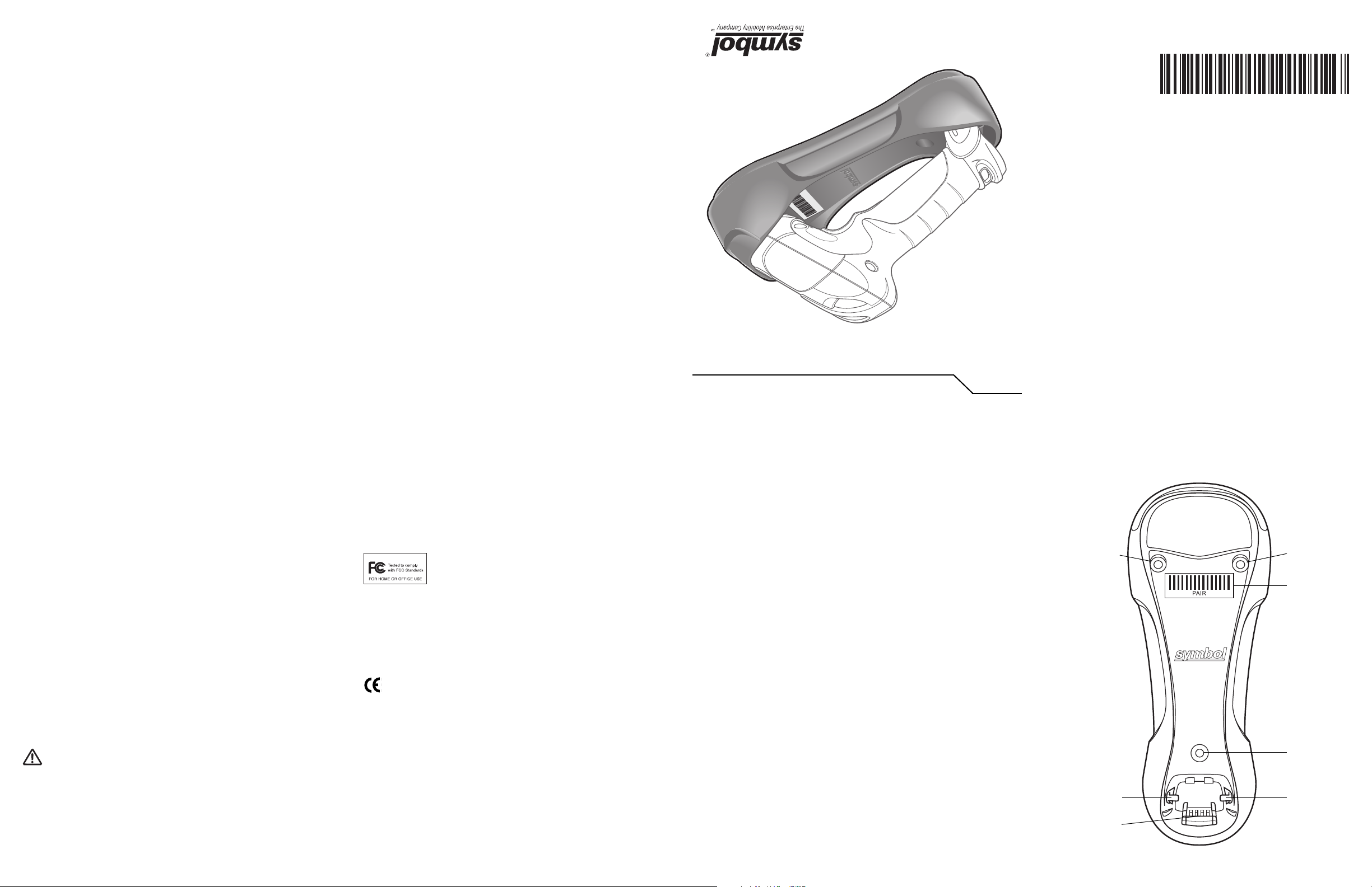
Cradle Parts (Front)
Mounting
Screw Hole
Latch
Charging/
Communication
Contacts
Mounting
Screw Hole
Pairing Bar
Code
Mounting
Screw Hole
Latch
Page 2
Cradle Parts (Back)
Cable Hook
Rubber Foot
Mounting
Screw Hole
Power Cable Groove
Rubber Foot
Note: Do not use the rubber feet when mounting in a non-horizontal orientation.
Rubber Foot
Mounting
Screw Hole
Power Port
Host Port
Host Cable
Groove
Mounting
Screw Hole
Converter
Knob
Rubber Foot
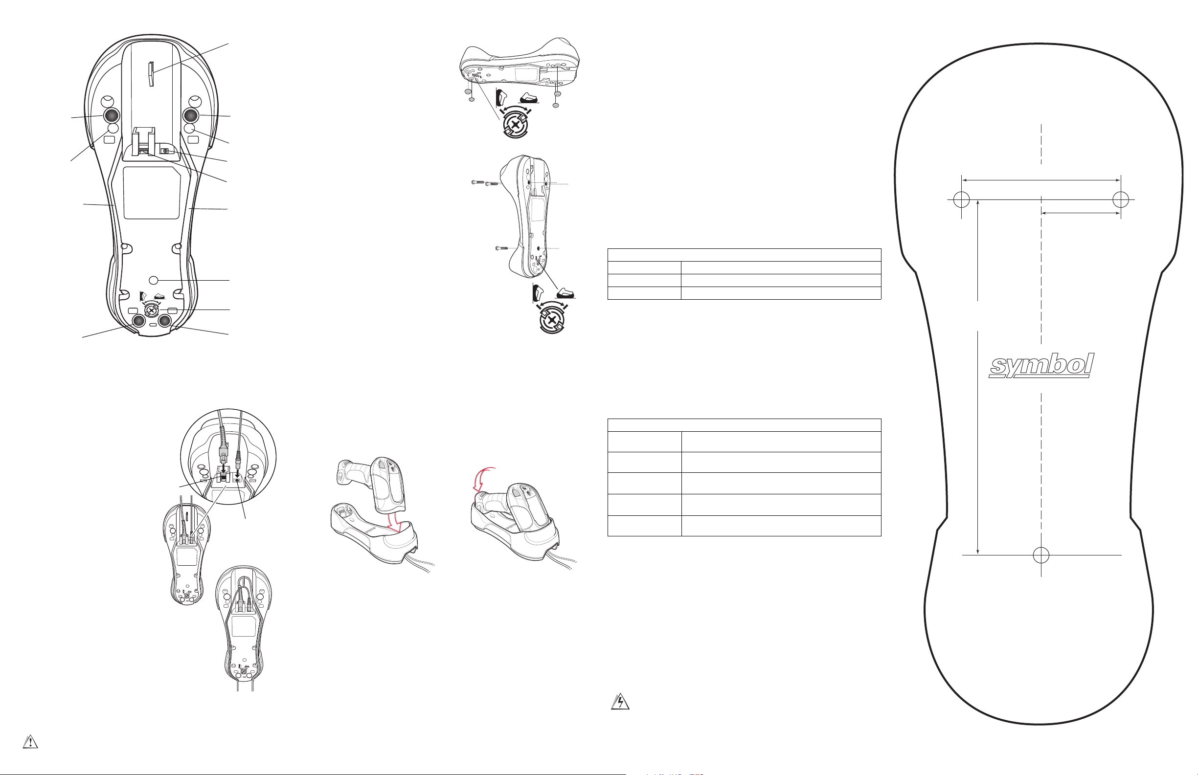
Mounting the Cradle
Horizontal Mount
1. Ensure the converter knob is in the
correct position, shown at right.
2. If mounting the cradle horizontally
where no fastening is necessary,
peel the protective paper from the
back of the rubber feet included
with the cradle packaging, and attach the feet to the cradle at the
indentations in the plastic. These
feet provide traction and prevent
surface damage.
Non-Horizontal Mount
To mount the cradle on a non-horizontal surface:
1. Use a Philips screwdriver to turn the converter
knob to the position shown at right. The latches
protract to engage the depressions at the base
of the scanner’s handle.
2. Attach the interface and power cables to the
appropriate ports (see Cradle Connections).
3. Press the cables into the cable grooves.
4. Position the cradle on the mounting surface.
5. Mark the surface through the three holes on the
bottom of the cradle, or use the mounting template to determine the location of the screw
holes.
6. Pre-drill holes to accommodate three 1.5" #8
Philips head screws.
7. Attach the cradle securely to the surface.
8. Place the scanner in the cradle.
Note: Do not use the rubber feet when mounting in
a non-horizontal orientation.
Converter Knob:
Horizontal Position
Converter Knob:
Non-horizontal Position
Lost Connection to Host
If scanned data does not transmit to the cradle’s host, ensure that all cables are firmly inserted
and the power supply is connected to an appropriate AC outlet. If scanned data still does not
transmit to the host, reestablish a connection with the host:
1. Disconnect the power supply from the cradle.
2. Disconnect the host interface cable from the cradle.
3. Wait three seconds.
4. Reconnect the host interface cable to the cradle.
5. Reconnect the power supply to the cradle.
6. Reestablish pairing with the cradle by scanning either pairing bar code.
Charging the Scanner Battery in the Cradle
To charge the scanner battery, place the scanner in the cradle (see Inserting the Scanner in the
Cradle). The battery begins charging within five seconds. A complete charge can take up to four
hours, depending on the remaining charge in the battery.
LED Charging Indications
The green LED indicates charging activity (see the table below). If the scanner is charging in fast
mode (non-bus powered mode), the green LED blinks at a fast rate. If the scanner is charging in
slow mode (bus-powered mode), the LED blinks at a slow rate.
If the red LED begins flashing, indicating a charging problem, remove the scanner from the cradle
and replace the battery. If the red LED continues flashing, contact a Symbol Support Center.
Standard Use LED Sequences
Off
Green
Red
No power is applied to the scanner, or the scanner is on and ready to scan.
A bar code was successfully decoded.
A data transmission error or scanner malfunction occurred.
Mounting Template
2.26"
[57.28mm]
1.13"
[28.64mm]
5.05"
[128.27mm]
Cradle Connections
Important: Connect the interface cable and
power supply in the following order to ensure
proper operation of the scanner and cradle:
1. Insert the interface cable into the cradle’s
host port.
2. Connect the other end of the interface cable
to the host.
3. Connect the power supply to the cradle’s
power port if required by the interface, or to
allow fast charging of the scanner.
4. Connect the appropriate cable to the power
supply and an AC power source.
5. If applicable, thread the interface cable over
the cable hook and run the host and power
cables into their respective cable grooves.
6. If necessary, scan the appropriate host bar
code (for non-autodetected interfaces). See
the Product Reference Guide.
Changing the Host Interface
To connect to a different host, or to the same
host through a different cable:
1. Unplug the power supply from the cradle.
2. Unplug the interface cable from the host.
3. Connect the interface cable to the new host,
or the new interface cable to the existing
host.
4. Reconnect the power supply.
5. If necessary, scan the appropriate host bar
code (for non-autodetected interfaces). See
the Product Reference Guide.
Host
Port
Power Port
Inserting the Scanner in the Cradle
To insert the scanner in the cradle:
1. Insert the scanner top first.
2. Push the handle until it clicks into place, engaging the contacts in the cradle and scanner.
Sending Data to the Host Computer
The cradle receives data from the scanner via a wireless radio connection and transmits it to the
host computer via the host cable. The scanner and cradle must be paired for successful wireless
communication.
Pairing
Pairing registers a scanner to the cradle. The STB3478 is a multipoint cradle, and can connect to
up to four scanners at a time. The cradle includes pairing bar codes on both its front and back.
During pairing, the scanner and the cradle exchange information. A short low-high beep sequence
indicates successful pairing. Four low, long beeps indicate failure, or an unsuccessful pairing.
To pair the scanner with the cradle, scan either pairing bar code.
Charging Use LED Sequences
Green Slow Flash
Green Fast Flash
Red fast flash (two
flashes per second)
Red slow flash (one
flash per second)
Red and green flash
For more details about LED indications, refer to the LS 3478 Product Reference Guide.
The scanner is in the cradle and is charging in slow mode (used when the cradle
is powered from the USB bus).
The scanner is in the cradle and is charging in rapid mode (used when the cradle
is powered from an external power supply).
Overcharge condition. Contact the Symbol Support Center.
Low battery voltage. Replace the battery.
Temperature fault. Move the cradle to a location where the temperature is
o
- 40o C; optimal charging temperature is 5o - 35o C.
0
Using the USB Interface to Supply Power
When the cradle is connected to the host via the USB interface, the USB port can power the cradle
instead of an external power supply. In this mode, the cradle can only charge the scanner battery
in singlepoint mode. To charge a scanner in multipoint mode, an external power supply is required.
Troubleshooting
If the cradle does not work after following the previous procedures:
• Check the system power.
• Check for loose cable connections.
• Check that the scanner is inserted properly in the cradle.
• Check that the host settings are correct and the cradle is connected to the appropriate port on
the host.
Do not pour, spray, or spill any liquid on the cradle.
If the scanner does not recognize the host, disconnect the power supply, then
reconnect after connecting the host cable.
Dimension tolerance = ± 0.01 inch (± 0.25 mm)
 Loading...