


Uninterruptible Power System
Smart Series Service Manual
Smart 700/1000/1400VA
210/220/230/240V 50/60HZ
Sysgration Ltd.
E-mail:ups@sysgration.com
http://www.sysgration.com
Version Date
V1.0 2004/02/06
第 1 頁,共 1 頁

Description
1.0 Generic description
2.0 Panel Diagram
3.0 Electronic Function
1. Diagram Description
2. E.M.I. filter & surge protection
3. AVR circuitry
4. AC/DC CHARGER Diagram
5. DC POWER CONTROL
6. FULL BRIDGE INVERTER Diagram
7. MICROPROCESSOR
8. AC detect and Frequency Detect diagram
9. INV detect diagram
10. Load capacity detect diagram
11. RS-232 communiation port
12. Buzzer
5.0 Problem Solution
5.1 Voltage Detect
5.2 UPS status
5.3 Notice
第 2 頁,共 2 頁

1.0 Generic Description
Smart UPS is an extremely reliable sine wave uninterruptible power system designed to keep
computers and peripheral devices such as monitors, storage subsystems, modems, tape drives,
etc. performing from utility line failures which could result in damage of data. In the event of
utility failure, the Smart UPS supplies power to your equipment derived from a battery within
the UPS and provides visual and audible indicators which alert you to utility line failures.
Therefore, the user has ample time to save file and close operations. Whenever the Smart UPS
is plugged in, the Smart UPS maintains the battery in a charged condition and serves to protect
your equipments from surges and noise brought from utility.
The main features include:
Pure sine wave output.
Automatic Voltage Regulation (AVR).
Advanced equipment & data protection from blackouts, brownouts, sags,
AC line noise and surges.
Adjustable input power range settings to meet your power source requirement.
Full analytical high performance micro processor control with true RMS synchronous calculation
Intelligent battery management for battery status, battery power saving & battery replacement control.
DC direct start up capability, complete diagnostic indication and control.
Standard RS-232 communication interface.
Telephone RJ11 & Network RJ45 surge protection.
Expansion slot is for optional SNMP CARD for network management / monitor.
Smart series include 700VA/1000VA/1400, Smart series have 50Hz & 60Hz autosensing
function.
第 3 頁,共 3 頁

2.0 Panel Diagram
1. ON/OFF SWITCH
2. ON LINE/AVR/ON BATT LED
3. INTERNAL FAULT LED
4. OVER LOAD LED
5. WEAK BATT LED
第 4 頁,共 4 頁

1. CIRCUIT BREAKER
SITE WIRNG FAULT
2. DIP_SW for output voltage adjustment
3. PHONE JACK
4. RS232 PORT
5. OUTPUT SOCKET
6. INPUT SOCKET
7. SNMP CARD SLOT
第 5 頁,共 5 頁

3.0 Specification
Specification 700VA/500W 1000VA/700W 1400VA/1000W
Processor RISC based micro processor
Detection
Protection
Continuous output
capacity
Surge energy
rating
Communication
Port
Indicators 4 LEDs indicating on-line, on batt, overload, bad batt & system
Input socket IEC 320 male socket
Output socket
Operating
environment
default
Frequency Range
Voltage Range
default
Frequency Range ± 5% from the nominal input frequency
Wave Form True Sine wave
Surge Protection 440 Joules
Voltage 210/220/240VAC user adjustable
Output Voltage
Regulation
Frequency ± 1% synchronized to line
Typical Transfer
Time
Hot Swappable
Battery
Battery Capacity Two 12V, 7ah Two 12V,12ah Four 12V, 7ah
Typical Back Up
Time
(One 17"Monitor)
Recharging Time
Physical Dimension
WxHxD
Shipping Dimension
WxHxD
UPS Weight 14.68kg 20.16kg 23.18kg
Power source voltage rms value,locked phase of frequency, output load,bad battery
condition,system fault
Over-current , short circuit ,latching shutdown , overload, brownout,blackout,input
breaker,RJ-11/45
5 minutes 5 minutes 5 minutes
(one time,10/1000 us waveform) 440 Joules
RS232 standard
3 x IEC320 & B type socket 5 x IEC320 & B type socket 5 x IEC320 & B type socket
0-40°C(32-104°F), 0-95% RH, non condensing
Input(Non Battery Operation)
165 to 280V Voltage Range
50/60 Hz auto sensing
Output( Non Battery Operation )
205 to 250 V
Output( Battery Operation )
± 4% until low battery warning
4-8 ms
Battery System
Yes
50 minutes 100 minutes 125 minutes
8 hours typical (battery voltage>85%),
12 hours max (battery voltage>90%),
Mechanical
140 x 156 x 370 mm 165 x 216 x 450 mm 165 x 216 x 450 mm
282 x 300 x 540 mm 275 x 340 X 560 mm 275 x 340 X 560 mm
第 6 頁,共 6 頁

4.0
1. Diagram
INPUT
FILTER
EMI
K2
T4
INVERTER
(FULL BRIDGE)
INPUT RELAY
AVR
CHARGER
CONTROL
BAT.
SW DI P-2
4
3
POWER
SUPPLY
KEY1
ON/OFF
KEY1
TEST/SILENCE
1
2
BAT-V
S1
RS-232 PWR
Vref&Mic-PWR
LINE-SENSOR
LINE-F
VCC
THERMAL
SENSOR
MICROCONTROLLER
RELAY
DRIVER
OUTPUT RELAY
K5
OUTPUT
CT1
CT
CURRENT
SENSOR
I-PEAK
PROTECT
GO TO GATE DRIER
INV-SENSOR
ERR AMP
GATE
DRIVER
DISPLAY
RS232
BUZZER
第 7 頁,共 7 頁
5
5
D
CB1
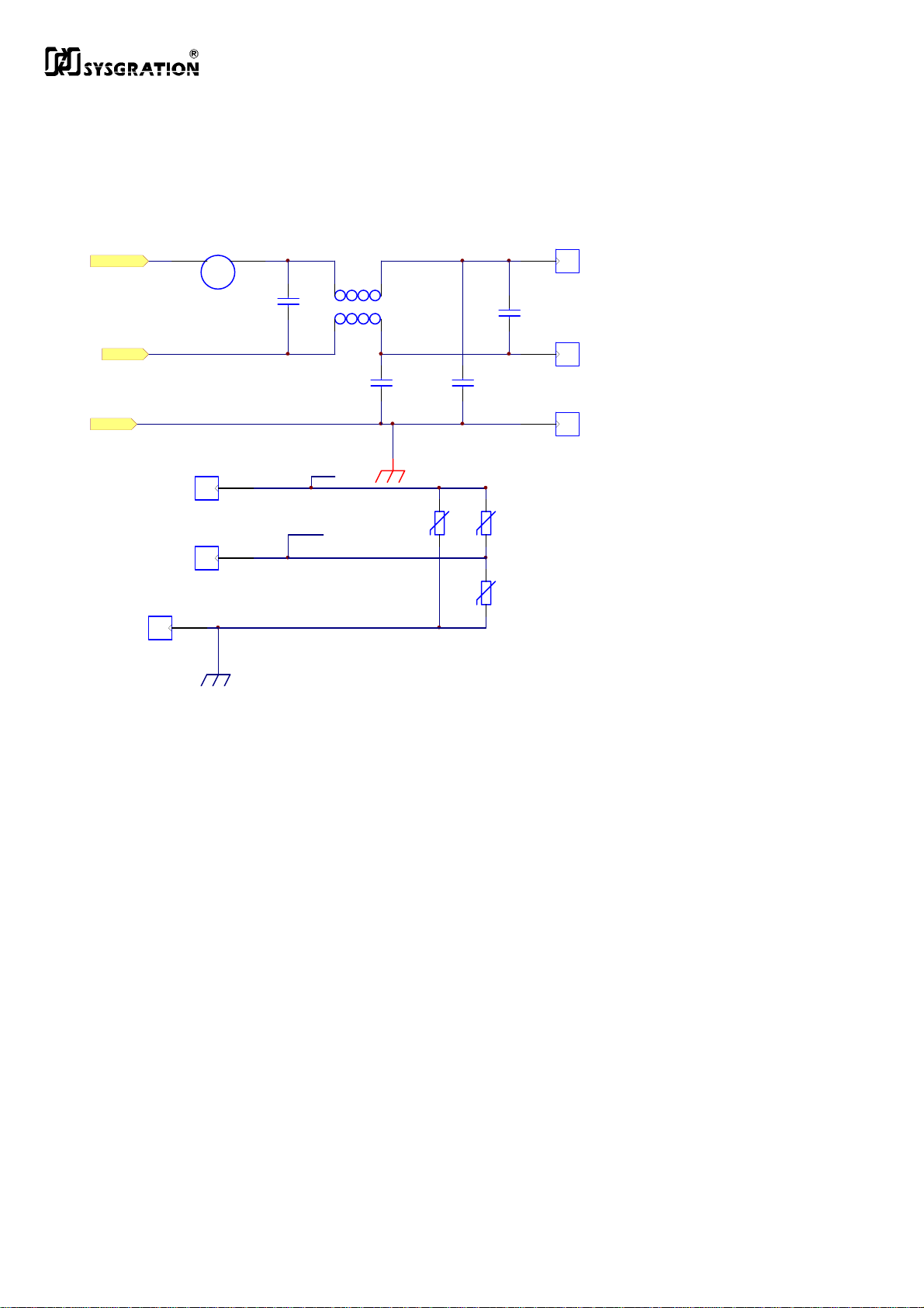
2. E.M.I. filter & surge protector
700VA: 5A 250V
CIRCUIT BREAKER
I/P
CN7
1000VA: 10A 250V
1400VA: 10A 250V
CB1
LINE
I/P
CN3
PC 250
CN4
PC 250
C53
CX105
NEU
LINE
T1
C51
CY472
20D471K
RV1
D20
GND
CN5
PC2
C55
C50
CY472
RV2
20D471K
D20
RV3
20D471K
D20
CX105
CN8
PC2
CN9
PA
LINE
NEU
GND
LINE
PC 250
甲、 工作原理
i. 由 CB1、T1、C21、C25、C26構成E.M.I. FILTER來過濾AC-LINE的
NOISE。
ii. RV1、RV2、RV3為電源SURGE保護模組,可吸收突波能量,型號為
471KD20,最高電壓為330V,吸收突波能量為110焦耳,一旦AC Line 輸
入電壓過高或是有雷擊之現象能量太大時,MOV會形成短路狀態,已達
到雷擊保護或電壓過高之保護。
乙、 關鍵技術
i. T1為依EMI調整,一般都在經多次測試固定之後,不得修改。
第 8 頁,共 8 頁

8
2,7
K4
3. AVR function circuitry
K1
6
BAT+
K1R
RELAY DP ST
4
5
3
7
8
3,6
1
BAT+
8
K2R
K2 SPDT/16A
BAT+
K3R
3,6
1
8
2,7
4,5
C28
4.7UF/350VAC
OP-N
K3
3,6
1
8
OP-L
2,7
4,5
SPDT/16A
3,6
1
8
TP3
TP4
TP
TP5
TP
TP7
TP
BAT+
K4R
CA2
TP
224/400V
250V
223.4V
199.3V
0V
EI-114X60/50/40
2,7
2,7
4,5
4,5
CN12
PC 250
CN13
PC 250
CN14
PC 250
CN16
PC 250
4,5
K5
SPDT/16A
BAT+
T4
3,6
1
8
K5R
RED/15V
BLK/0V
1
4
TP8
TP
TP9
TP
CT1
XF-14
PC 250
UPS
O/P
CN11
5
CN6
CT2
CT1
CT1
甲、 工作原理
i. 此部份電路K1為INPUT RELAY, K2 BOOST2 RELAY &K3 BOOST1
RELAY、K4 BUCK RELAY 、K5 OUTPUT RELAY。
ii. 當電壓正常時,K2、K3、K4不動作,電壓掉到BOOST1的額定電壓時,K3動
作,同理電壓掉到BOOST2的額定電壓時,K2、K3動作,當電壓升到BUCK的
額定電壓時,K4動作。
iii. 此電路利用變壓器的線圈及RELAY的切換來做AVR的動作。
乙、 Key technology
K1R
BAT+
R154
3.3K
R250
+BAT
BAT+
C68
100uF/25V
R156
5K1
R250
D2
SD
D1N4148
Q44
C1815
TO92
BOOST2
Boost2
INPUT
R170
200/2W
R1WS
R155
1K
R250
K2R
300/1W
Boos2
R71
R1WS
R75
1K
R250
BAT+
R67
3.3K
R250
C31
100u/25V
CE08
R79
5K1
R250
Q33
C1815
TO92
BAT+
Boost1
BAT+
K3R
R72
300/1W
R1WS
BOOST1
Boost1
R76
1K
R250
R68
3.3K
R250
C32
100u/25V
CE08
R80
5K1
R250
Q34
C1815
TO92
BAT+
Buck
BAT+
K4R
R73
300/1W
R1WS
BUCK
Buck
R77
1K
R250
R69
3.3K
R250
C33
100u/25V
CE08
R82
5K1
R250
Q35
C1815
TO92
BAT+
OUTPUT
Out
OUT
BAT+
K5R
R74
300/1W
R1WS
R78
1K
R250
R70
3.3K
R250
C34
100u25V
CE08
35V
R83
5K1
R250
Q36
C1815
TO92
此電路經由CPU的訊號驅動電晶體使RELAY的動作,RC為加速電路如R71、
C31&R72、C32…..等等,R67、R68、R69、R70、R154為RELAY洩放電阻。
第 9 頁,共 9 頁
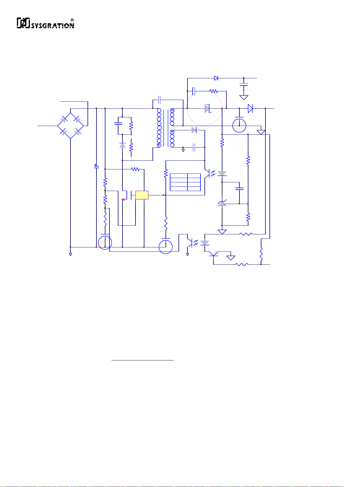
4. AC/DC CHARGER
R165
2K
C66
103J
U23
TL431
R168
Restart
C67
100u50V
RA2
2K
DA5
R167
5.1KF
RA5
27K
C63
104Z
SF35
R166
56KF
BAT+
CHG
立式
D43
43
12
100/1W
U21
PC 817
QA1
R162
U22
1N4148
12
C1815
C49
6
8
4
1N4148
PGND
R163
2.49KF
3KF
3.24KF
43
221J
D44
C64
103J
PC 817
SF35
C
35T3
1
R163
*
U24
1
C62
102/Y2
R164
6.8
700VA
1K0VA
1K4VA
NEU
4
LINE
1
3
D40
-+
2
2W10G
1000V 2A
D17
SF37
C60
68u/400V
R160
NC
R161
15KF
1/4W
RA3
1K
立式
R113
立式
C45
103
51K/3W
R159
水泥
68K/2W
R169
2M 1/2W
7
D
S
4
2
L
F
X
TOP245Y
5
3
CA1
PGND PGND
22U/50V
C65
47u50V
甲、 工作原理
i. 此充電電路為 FLY-BACK 架構,充電電流約 I
ii. 輸出電壓的穩壓迴授由R166、R167的分壓得到,其電阻比率計算如下
iii. Vout=V
iv. 此充電電路開關由Vcomp控制,當Vcomp 達到2.5V時關掉充電,若上述
條件不存在時則充電。
v. 當市電源進入時,經 D40而對C60充電而變成直流電壓根號2Vrms,此直流
經 T3 而到 U24的 DRAIN,而使得U24 CONTROL充電,當CONTROL
電壓充到了約5.7V,而使得U11起振動作,大約130KHz。
BAT. Vcomp=2.5V
Vou
t *
R167
R166+R167
BAT.±0.2A
=Vcomp
第 10 頁,共 10 頁

vi. 而此脈衝經T3而由PIN 4、5、6、8產生電壓,PIN6、8所產生的電壓經D43
整流而產生直流電壓,經C67及D43而供應充電電流給電池。
vii. 而由PIN4、5所產生的電壓經D44之後變成直流,經R163之後供應給U24
之CONTORL繼續提供5.7V之電壓,而流入CONTORL之電流為調整PWM
之寬度,而達到控制充電電流之目的,當流經CONTORL的電流越大則充
電電流越小,可由R163調整。
viii. 當電池電壓達到了V
BAT電壓經R166、R167分壓後會使得U23導通,而使
的U21動作,致使經D44所產生之直流經U21而流入U24之CONTORL,而
達到截止充電之目的。
乙、 關鍵技術
i. U24之TOP24XY為可使用於國際上各種電壓,由80V致265V都可使用,也
可設計成單一地區之使用,如115V或是220V,如設計成國際電壓都可使
用,則其功率只有30瓦,如設計成單一地區之使用則可達到45瓦,本電路
之設計是國際多種電壓都可使用之電路,故功率最大為30瓦。
ii. 設計可使用於國際上各種電壓,或設計成單一地區之使用電壓,重點為變
壓器T3,故變壓器為設計重點。
iii. U24之TOP24XY之使用需多注意EMI之問題較難處理,但使用較為方便,
亦能輕易設計充電電壓及電流。需注意散熱問題
iv. 當充電電流過高可將電阻R163改小,反之則可將充電流加大。
v. 將原結構改為過高壓判斷,而另外再加U22由CPU的電池判斷來控制。
vi. TOP24XY有外部限流(輸出之最大電流)&外部限壓(輸入最大電壓)分別由
R160、R161調整限制輸出之最大電流,R160 OPEN R161 SHORT為此原件
的最大電流,跟R169調整限制輸入的AC電壓,當電壓過高時電路會自動關
畢
,以防止過大電壓燒毀電路。
vii. DRAIN的振幅必須工作在700V以下,因此C45、R159主要的目的是將電壓
箝制在700V下, 防止過大電壓燒毀電路。
第 11 頁,共 11 頁

5. DC POWER CONTROL
Restart
BAT+
R56
10K
PWR
R98
10K
R250
R104
3K
R250
Q39
C1815
TO92
22K
R250
R86
TO92
Q37
MPSA56
R96
3K 1/2W
D20
D21
D4148
D4148
KEY1
-9V
D4148
D4148
DC GND
VBAT
R146
1K5
R2WS
5V
10u/50V
C48
100u/50V
CE02
Z1
12V
R97
10K
R250
KEY
C40
104Z
CC02
VCC 1
C24
C36
22u/50V
CE02
D38
1N4007
DO1A
C47
CC02
R2WS
D14
1N4148
471 1KV
R147
100
RA1
33R/2W
VCC
10UF/50V
CX
NC.
R85
1K
6
T2
7
4
1
EE16
5
6
7
8
U8
D
NC
VCC
GND
TAD16831/2/3
Q38
D667
TO92
1
U10
2 3
TL431
TO92
D30
1N5819
5V
R87
10K5F
R250
R102
10.2KF
R250
+9V
DC GND
C51
470u/25V
CE02
C58
103
CC02
C23
10u/50V
Q43
C1815
TO92
C53
104
CC02
R250
R149
1K
VCC 1
R250
R148
680R
Z3
12V
12V
100u/25V
CE08
C38
103
CC02
D13
IN5819 1A
4
D
3
NC
2
FB
1
NC
C37
5
6
2
3
甲、 動作原理
i. 此DC電源電路為 FLY-BACK 架構。
ii. 輸出電壓的穩壓迴授由Z3決定,當VCC電壓到達12V時,Q43導通FB由HI
轉LOW。
iii. 當電源進入時,經KEY而對CUP下達命令使Q37導通,對U8產生12V電源供
應,而電池電壓經T2而到U8的DRAIN,而使得U8 FB充電,當FB電壓充到
了約5.7V,而使得U8起振動作用,大約100KHz。
iv. 而此脈衝經T3而由PIN 2、3、5、6、7產生電壓,PIN2、3所產生的電壓經
D30整流而產生直流電壓,經C51及Z3而供應12V電壓。
v. VCC經D38進入Q38B及
U10,而使得Q38輸出一穩定之5.1V之電源,U10
之功能為使Q38之輸出穩定在5.1V。
vi. 5.1V由TL431經R87、R102取得分壓,以控制5.1V維持在5.12V±0.02V以
內。
第 12 頁,共 12 頁
C
D
D
乙、 關鍵技術
i. U8之TDA16833之使用需多注意EMI之問題較難處理,但使用較為方便,
亦能輕易設計充電電壓及電流。需注意散熱問題
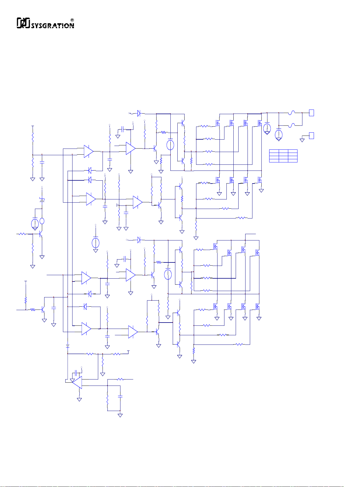
6. FULL BRIDGE INVERTER
INV-DIS
R250
D1
VCC
1N4148
VCC
4.8V
4.8V
R1/4W
VCC
R40
2K
R1/4W
104Z
4.8V
15KF
R18
10KF
C19
104Z
R12
VCC
3
7
+
U1:1
6
-
LM339
12
U1:4
8
9
C7
104Z
CC02
VCC
VCC
C20
3
7
+
U5:1
6
-
LM339
12
U5:4
8
-
9
+
LM339
5V
OCP
C16
472J
D3
1N4148
D4
1N4148
2
D9
1N4148
13
VCC
R4
10K
R1/4W
2
C4
101
CC02
VCC
R13
10K
R1/4W
13
C6
4.8V
101
CC02
VCC
C25
10u50V
VCC
R25
10K
R1/4W
C12
101
CC02
VCC
R31
10K
R1/4W
C13
101
CC02
R38
R47
22K
68K
R48
22K
R1/4W
5V
R7
10KF
D35
104Z
1
LM358
1N4148
C22
5
+
U1:2
4
-
LM339
11
+
U1:3
10
-
LM339
5
+
U5:2
4
-
LM339
D10
1N4148
11
+
U5:3
10
-
LM339
R41
220K
VCC
R1/4W
8
3U6:1
+
2
-
4
PWM
R10
C5
10KF
104Z
CC02
VCC
ZD1
6V2
C14
+
R171
BZ1
-
BZ1205S
Q28
C1815
TO92
R39
5K1
R250
60Hz
SD
C15
Q30
103J
C1815
3K
CC02
10u50V
CE02
R36
1K
5V
R172
1K
-
+
LM339
1
R1/4W
1
R3
4K7
R1/4W
R24
4K7
14
D5
1N4148
VCC
R1
2K2
R1/4W
R157
100R/1W
Q6
C1815
TO92
R42
10K
R1/4W
VCC
R55
2K2
R14
R1/4W
4K7
R1/4W
14
R1/4W
R22
2K2
VCC
R32
4K7
R1/4W
Q20
C1815
TO92
R158
100R/1W
R20
2K2
R1/4W
Q14
C1815
TO92
Q29
C1815
TO92
R37
10K
C3
22u50V
CE02
C11
22u50V
CE02
R1/4W
Q1
C1815
R2
TO92
15R
R1/4W
R6
R5
15R
15R
R1/4W
R1/4W
R8
15R
R1/4W
RA6
Q7
10K
A1015
R9
TO92
15R
R1/4W
VCC
R11
Q12
15R
R1/4W
C1815
TO92
R21
15R
R1/4W
R26
15R
R1/4W
Q21
A1015
TO92
VCC
Q26
C1815
TO92
R17
15R
R1/4W
Q27
A1015
TO92
Q13
A1015
TO92
Q15
C1815
TO92
R15
15R
R1/4W
RA7
10K
R23
50N06
15R
TO220
R1/4W
R27
15R
R1/4W
R28
15R
R1/4W
RA8
10K
R30
50N06
15R
TO220
R1/4W
R33
15R
R1/4W
RA9
10K
Q16
Q22
Q2
50N06
TO220
Q8
50N06
TO220
R29
15R
R1/4W
R34
15R
R1/4W
R16
15R
R1/4W
50N06
TO220
Q23
50N06
TO220
50N06
TO220
50N06
TO220
Q17
Q3
Q4
Q5
50N06
50N06
TO220
TO220
Q11
Q10
Q9
R19
15R
R1/4W
R35
15R
R1/4W
50N06
TO220
50N06
TO220
50N06
TO220
Q18
Q24
BAT+
50N06
TO220
50N06
TO220
50N06
TO220
Q19
Q25
BAT+
C1
3300u35V
700VA
1K0VA
1K4VA
C2
3300u35V
F1
40A
30A
40A
F3
F3
DNI
30A
40A
PA
CN2
PA
第 13 頁,共 13 頁

A. 動作原理
i. 本電路利用MOSFET構成全橋方式將PWM透過U1B、U1C輸出正反的訊
號,再經由U1A、U1D反相放大,同理;60Hz透過 U5B、U5C輸出正反的訊
號U5A、U5D
反相放大後,經過電晶體推挽放大後再推動MOSFET切換成近似市電交流電源
之正弦波輸出。
ii. 左半橋為PWM組成的正反訊號,右半橋為60Hz組成的正反訊號,經由(AVR
電路)T4變壓器的低壓側線圈耦合到高壓側線圈与C28成為一低通電路濾
成正弦波。
iii. 輸出波形由60HZ与PWM依相位差異,而控制輸出波形之PWM,由微處
理器負責控制。當輸出負載加重時,則將PWM波寬加寬,反之則將波寬縮
小。
乙、 關鍵技術
i. 輸出是決定於PWM及60Hz之波形相位,所以當上下半橋相位相反時則輸
出便可得到如同市電之電源。
ii. 需注意MOSFET之溫度,及最大導通電流。
iii. 因此OCP訊號大過U6A第3腳時,U6A第1腳由HI轉LOW,
經由C16&R48振
盪,關閉PWM及60Hz訊號,保護MOSFET。
iv. INV-DIS為HI時,Q30導通,亦關閉PWM及60Hz訊號,結束INV輸出;CPU在
Reset之前所有的腳有將近75ms為浮動的狀態,因此在開機之前必須將INV
解除,所以INV-DIS必須為HI的訊號。
第 14 頁,共 14 頁

7. MICROPROCESSOR
INV--AV
C39
224
INV-V
LINE-AV
C46
22u50V
Line-V
22u50V
C44
224
LOAD
5V
C42
Y1
4MHz
U2
13
OSC 1
14
OSC 2
1
MCLR
2
RA0/AN0
3
RA1/AN1
4
RA2/AN2
5
RA3/AN3
6
RA4/T0CKI
7
RA5/AN4/S S
8
RE0/RD/AN5
9
RE1/WR /AN6
10
S1 Out
RE2/CS/AN7
11
VDD
32
VDD
C10
104Z
CC02
12
VSS
31
VSS
PIC16F 74
DIP40
C69
104Z
C9
10u50V
CE02
5V
BAT-V
KEY
THE RMA L
RC 0/T1OS O/T1CKI
RC1/T1OSI/CCP2
RC3/SCK/SCL
RC4/SDI/SDA
RC6/TX/CK
RC7/RX/DT
RC2/CCP1
RC5/SDO
RB0/I NT
RB1
RB2
RB3
RB4
RB5
RB6
RB7
RD0/PSP0
RD1/PSP1
RD2/PSP2
RD3/PSP3
RD4/PSP4
RD5/PSP5
RD6/PSP6
RD7/PSP7
5V
U3
8
R250
7
6
5
VDD
TEST
SCL
5V
15
BU ZZE R
16
60Hz
17
PWM
18
23
24
25
TXD
26
RXD
33
34
IN
35
Boost1
36
Boost2
37
Buck
38
39
40
19
PWR
20
CHG
21
INV-DIS
22
27
LED1
28
LED2
29
LED3
30
LED4
R89
10K
R250
R60
10K
FRE Q
C8
104Z
VSS VEE
NC
NC
NC
GNDSDA
24C01
A. 工作原理
1. PIC16C74係一種具有A/D轉換、PWM輸出功能,可程式微處理器,使用之震蕩
頻率為4MHz。
2. 利用S1調整阻值輸入A/D腳作為INV輸出電壓的調整。
3. 利用EEPROM來增加其記憶体。
4. 控制AVR輸出、INV訊號輸出、充電判定、有無市電判定、頻率判定、負載
判定、RS232通訊及顯示和告警。
第 15 頁,共 15 頁

8. AC DETECT/Frequency Detect
R122
200KF
R250
R141
R130
200KF
R250
200KF
R250
R250
R125
200KF
R250
R136
200KF
R250
R137
200KF
LINE
NEU
R128
100KF
R250
R139
100KF
R250
R129
100KF
R250
5V
R140
100KF
R250
R133
6.04KF
R250
R135
6.04KF
R250
R134
VCC
3
+
2
-
200KF
VCC
5
+
6
-
C35
104Z
411
U7A
1
LM324
R250
411
U7B
7
LM324
D25
1N4148
D26
1N4148
R120
20KF
R250
R127
20KF
R250
R143
2KF
R250
R144
200KF
R145
2KF
RA10
3.3K
Line-V
Line-AV
RA4
150K
5V
R142
10K
R250
FRECQ
Q42
C1815
TO92
A. 工作原理
i. U7A、U7B 為一誤差放大器其接收市電訊號,由電阻將訊號衰減到控制電路
可接受的範圍, U7A、U7B 的輸出波形類似全波整流後的輸出。此訊號如
經過R127与CPU上的C44濾波後產生的電壓被命名為LINE-AV,其送給CPU
作市電波形電壓的快速監視。此訊號如經過 R120 與 CPU 上的 C42 濾波後
產生電壓後產生的電壓被命名為LINE-V,其送給 CPU 作對外通訊時提供一
個平穩的訊號供 A/D 轉換使用。
2.Q42 其接收市電訊號將其切割成一方波訊號供給 CPU 作為相鎖的依據。
B. 關鍵技術
1. LINE、NEU同時偵測,提高更快速偵測斷電監視。
2. 利用兩個全波整流器來對LINE与NEU整流後,提供CUP漣波&直流的訊號作為
判斷。
3. 電阻分壓為關鍵技術,注意須以最高之市電電壓作為依據,其LINE-AV最高點
不得超過5.12V,否則CPU會無法判決。
4. 需注意市電電壓及頻率偵測之LM324之輸出及輸入之LAYOUT迴路以免受
其他大信號之影響。
第 16 頁,共 16 頁

九. INV DETECT
R250
R250
R109
100KF
R92
100KF
OP-L
OP-N
VCC
R250
R93
100KF
R99
6.04KF
R250
5V
R105
6.04KF
R250
R250
R110
100KF
R108
200KF
200KF
R94
200KF
R250
200KF
R111
200KF
R250
R88
R103
R107
200KF
R250
R250
R250
R250
411
10
9
U7C
+
8
-
LM324
D19
1N4148
R101
200KF
R250
VCC
R84
20KF
R250
R90
20KF
R250
411
U7D
12
+
13
14
-
LM324
R118
200K
R250
D22
1N4148
R112
2.46KF
R250
INV-V
INV-A V
RX
NC.
A. 工作原理
同上因此不再贅述
B. 關鍵技術
同上因此不再贅述
十.Load detect
CT1
CT2
A.工作原理
DA1
DA2
DA3
1N5819
1N5819
1N5819
1N4148
D12
R59
10R/1W
R1W
R52
1KF
R250
5 U6:2
+
6
-
700VA :R53 30KF
1KVA :R53 21KF
1K4VA :R53 15KF
R53
*
R250
7
LM358
OCP
R57
20KF
R250
D11
1N4148
R54
1M
R250
LOAD
C18
10u50V
CE02
ii. 由(AVR電路)CT 透過D37濾成直流訊號經由U6b反相放大器,將負載之狀態
傳回CPU,做為是否可以繼續工作的判斷。
第 17 頁,共 17 頁

iii. CT 透過D37先將負載訊號波形(AC)轉換為直流訊號其波形類似全波整
流。U6b將此訊號做适當的放大後由D11、R54、R57、C18組成的電路將此
訊號濾波成近似RMS值的電壓交給CPU處理。
B.關鍵技術
1. 由CT 透過D37濾成直流訊號經由U6b反相放大器,產生的OCP可以立即反映輸
出過大電流的時間,也就是在電池模式下,能瞬間保護INV電路上的MOSFET,使
之不易損壞。
2. D12可使阻性載及容性載近似,以方便給CPU作偵測,其工作原理是利用電流
流經的方向不同來應用。
第 18 頁,共 18 頁

十一.RS232 communication port
BAT-LO
AC
-FAIL
5V
AC-FAIL
U15
U17
R106
10K
R250
U13
O/Pof f
AC-FAIL
+9V
R115
10K
R250
DB9-TXD
O/Pof f
AC-FAIL
DB9-RXD
5V
R124
10K
R250
R138
470
R250
DB9-TXD
DB9-RXD
+9V
R126
10K
R250
U18
5V
AC FAIL/NO
U19
+9V
R153
7.5K
+9V
-9V
R150
10K
R151
3K
R100
1K
R250
R250
U11
U12
R152
240
R250
5V
R95
1K
R250
-9V
TXD
JP3
1
6
2
7
3
8
4
9
5
RXD
DB9
15
RXD
14
10K R250
+9V
R81
10K
R250
U20B
4053
U20A
4053
R65
F7
PICO3A
SNMP-TXD
10
11
3K R250
10K R250
1
2
13
12
R63
R61
SNMP-TXD
DB9-TXD
SNMP-RXD
PTC2
DB9-RXD
P4KE6.8A
+9V
Q31
A1015
TO92
JP2
12
34
56
78
910
11 12
13 14
15 16
17 18
19 20
HEADER 10X2
CN10X2
PTC1
P4KE6.8A
SNMP-RXD
A.工作原理
1.將CPU的通訊資料透過隔離的光耦合器傳送給監視UPS的電腦。
B.關鍵技術
2.注意光耦合的驅動電流及導通的斜率,因此其分壓的阻值&驅動的阻值。
十二.B uzzer
BUZZER
BUZZER
R36
1K
R250
C14
10u50V
CE02
R39
5K1
R250
VCC
+
-
ZD1
6V2
BZ1
BZ1205S
Q28
C1815
TO92
A.工作原理
第 19 頁,共 19 頁

1. CPU控制Q28"HI"、"LO"來達成。
2. (Bz1205S)為自振式Buzzer,因此只需要提供"HI"、"LO"就可工作。
B.關鍵技術
1. 利用ZD1提供Buzzer的工作電壓。
2. C14是為了當VCC電壓有變化時,仍然能將Buzzer的工作電壓穩定住。
第 20 頁,共 20 頁

5.0 故障排除
一般線路故障異常在 ICT 階段應可診斷排除,以下為工程二部提供故障排除之方法
5.1 檢查電壓
當電壓指示燈亮起時:
1.確認電池電壓是否良好(電壓大於 10V,充電時不會突然昇高)若電池不良則換電池
2.量測充電電壓是否大於30V,若無則從F1 FUSE查起,檢查U24 TOP24X是否燒毀,D43
二極體是否正確動作
3.VCC,+5.12V,BAT-ADV 電壓是否正常
4.若上述動作正常則查看 INV MOSFET 及推動 INV 的電晶體是否已經燒毀?
5.2 UPS 無反應
當電源開關切換後 UPS 無反應時:
1.請查看 VCC 是否為 12V 左右,若有則查看 5.12V 是否正常,5.12V 不對則 U10 TL431
會損壞
2.無12 V時應檢查 U8的第7腳是否為12V,且第5腳為100KHz的PWM波形,D30”-“電
壓應在 12V 左右,若上述皆正常就看 Z3 或 Q43 是否有損壞
5.3 注意事項
在進行維修時應先將電路切割成幾個 PART,再針對故障的部份進行維修的動作。維修
時請注意下列幾點:
1.銅箔是否焦黑。
2.電容,電阻是否變質。
3.請在確定相關電路工作正確後才對 IC、CPU 進行檢測;請使用示波器檢測
其工作狀態作為判斷的依據。
第 21 頁,共 21 頁
 Loading...